EP1326355A2 - Exploitation of null packets in packetized digital television systems - Google Patents
Exploitation of null packets in packetized digital television systemsDownload PDFInfo
- Publication number
- EP1326355A2 EP1326355A2EP03000152AEP03000152AEP1326355A2EP 1326355 A2EP1326355 A2EP 1326355A2EP 03000152 AEP03000152 AEP 03000152AEP 03000152 AEP03000152 AEP 03000152AEP 1326355 A2EP1326355 A2EP 1326355A2
- Authority
- EP
- European Patent Office
- Prior art keywords
- data
- auxiliary
- multiplexer
- null
- encoder
- Prior art date
- Legal status (The legal status is an assumption and is not a legal conclusion. Google has not performed a legal analysis and makes no representation as to the accuracy of the status listed.)
- Granted
Links
Images


Classifications
- H—ELECTRICITY
- H04—ELECTRIC COMMUNICATION TECHNIQUE
- H04N—PICTORIAL COMMUNICATION, e.g. TELEVISION
- H04N21/00—Selective content distribution, e.g. interactive television or video on demand [VOD]
- H04N21/20—Servers specifically adapted for the distribution of content, e.g. VOD servers; Operations thereof
- H04N21/23—Processing of content or additional data; Elementary server operations; Server middleware
- H04N21/236—Assembling of a multiplex stream, e.g. transport stream, by combining a video stream with other content or additional data, e.g. inserting a URL [Uniform Resource Locator] into a video stream, multiplexing software data into a video stream; Remultiplexing of multiplex streams; Insertion of stuffing bits into the multiplex stream, e.g. to obtain a constant bit-rate; Assembling of a packetised elementary stream
- H04N21/23611—Insertion of stuffing data into a multiplex stream, e.g. to obtain a constant bitrate
- H—ELECTRICITY
- H04—ELECTRIC COMMUNICATION TECHNIQUE
- H04J—MULTIPLEX COMMUNICATION
- H04J3/00—Time-division multiplex systems
- H04J3/16—Time-division multiplex systems in which the time allocation to individual channels within a transmission cycle is variable, e.g. to accommodate varying complexity of signals, to vary number of channels transmitted
- H04J3/1682—Allocation of channels according to the instantaneous demands of the users, e.g. concentrated multiplexers, statistical multiplexers
- H—ELECTRICITY
- H04—ELECTRIC COMMUNICATION TECHNIQUE
- H04N—PICTORIAL COMMUNICATION, e.g. TELEVISION
- H04N21/00—Selective content distribution, e.g. interactive television or video on demand [VOD]
- H04N21/20—Servers specifically adapted for the distribution of content, e.g. VOD servers; Operations thereof
- H04N21/23—Processing of content or additional data; Elementary server operations; Server middleware
- H04N21/236—Assembling of a multiplex stream, e.g. transport stream, by combining a video stream with other content or additional data, e.g. inserting a URL [Uniform Resource Locator] into a video stream, multiplexing software data into a video stream; Remultiplexing of multiplex streams; Insertion of stuffing bits into the multiplex stream, e.g. to obtain a constant bit-rate; Assembling of a packetised elementary stream
- H04N21/23614—Multiplexing of additional data and video streams
- H—ELECTRICITY
- H04—ELECTRIC COMMUNICATION TECHNIQUE
- H04N—PICTORIAL COMMUNICATION, e.g. TELEVISION
- H04N21/00—Selective content distribution, e.g. interactive television or video on demand [VOD]
- H04N21/20—Servers specifically adapted for the distribution of content, e.g. VOD servers; Operations thereof
- H04N21/23—Processing of content or additional data; Elementary server operations; Server middleware
- H04N21/236—Assembling of a multiplex stream, e.g. transport stream, by combining a video stream with other content or additional data, e.g. inserting a URL [Uniform Resource Locator] into a video stream, multiplexing software data into a video stream; Remultiplexing of multiplex streams; Insertion of stuffing bits into the multiplex stream, e.g. to obtain a constant bit-rate; Assembling of a packetised elementary stream
- H04N21/2365—Multiplexing of several video streams
- H04N21/23655—Statistical multiplexing, e.g. by controlling the encoder to alter its bitrate to optimize the bandwidth utilization
- H—ELECTRICITY
- H04—ELECTRIC COMMUNICATION TECHNIQUE
- H04N—PICTORIAL COMMUNICATION, e.g. TELEVISION
- H04N21/00—Selective content distribution, e.g. interactive television or video on demand [VOD]
- H04N21/40—Client devices specifically adapted for the reception of or interaction with content, e.g. set-top-box [STB]; Operations thereof
- H04N21/43—Processing of content or additional data, e.g. demultiplexing additional data from a digital video stream; Elementary client operations, e.g. monitoring of home network or synchronising decoder's clock; Client middleware
- H04N21/434—Disassembling of a multiplex stream, e.g. demultiplexing audio and video streams, extraction of additional data from a video stream; Remultiplexing of multiplex streams; Extraction or processing of SI; Disassembling of packetised elementary stream
- H04N21/4347—Demultiplexing of several video streams
- H—ELECTRICITY
- H04—ELECTRIC COMMUNICATION TECHNIQUE
- H04N—PICTORIAL COMMUNICATION, e.g. TELEVISION
- H04N21/00—Selective content distribution, e.g. interactive television or video on demand [VOD]
- H04N21/40—Client devices specifically adapted for the reception of or interaction with content, e.g. set-top-box [STB]; Operations thereof
- H04N21/43—Processing of content or additional data, e.g. demultiplexing additional data from a digital video stream; Elementary client operations, e.g. monitoring of home network or synchronising decoder's clock; Client middleware
- H04N21/434—Disassembling of a multiplex stream, e.g. demultiplexing audio and video streams, extraction of additional data from a video stream; Remultiplexing of multiplex streams; Extraction or processing of SI; Disassembling of packetised elementary stream
- H04N21/4348—Demultiplexing of additional data and video streams
Definitions
- the present inventionrelates to systems and methods for multiplexing data from a plurality of data sources, and in particular to a method and system for substituting non-opportunistic auxiliary data for null data packets in a packetized data stream.
- Packet-based digital data transmission systemsare now commonplace.
- One example of such systemsare those which are used to transmit media programs such as television programs and audio data to subscribers via satellite.
- Such systemsare required to transmit many (200 or more) channels of data to subscribers over a transmission system that has a fixed throughput.
- packet-based television systemsmust fill all packets with data, and the packets must fill the entirety of a constant bit rate (CBR) transmission data channel.
- CBRconstant bit rate
- Television and audio signalsare "bursty" in that some pictures and some audio passages require more data to be faithfully reproduce the original signal than other pictures and passages.
- the statistical multiplexersupervises the encoders that encode and/or compress the incoming channels. This process includes negotiating and allocating throughput among each of the encoders.
- Statistical multiplexersare disclosed in U.S.
- Patent 5,854,658issued to Uz et al, U.S. Patent 5,864,557, issued to Lyons, and U.S. Patent 5,912,890, issued to Park, and U.S. Patent No. 6,208,666, issued to Lawrence et al., which references are hereby incorporated by reference.
- null data packetsare typically inserted into the data stream. This is performed so that the data channel is maintained at a CBR. While this technique is effective, the null packets used in this technique typically convey no useful information, and are therefore a waste of precious bandwidth.
- systemshave been devised which insert opportunistic (non-time critical data) into the data stream before being output from the statistical multiplexer.
- opportunisticnon-time critical data
- the present inventiondescribes a system and method for adding auxiliary data D A to an output data stream.
- the methodcomprises the steps of accepting a statistically multiplexed data stream having null data; and substituting at least a portion of the auxiliary data D A for the null data (null data is a global inclusive term meaning data that does not include anything useful) in the statistically multiplexed data stream.
- the efficient management of the replacement of null data with useful datamakes more efficient use of the bandwidth of the digital transmission system, effectively creating more payload capacity in existing transmission channels that can be used for video, audio, or other auxiliary data.
- FIG. 1is a diagram illustrating an overview of a media program distribution system 100.
- the media programs transmitted by the distribution system 100can include video programs, audio programs, or any other data.
- the distribution system 100comprises a control center 102 in communication with an uplink center 104 via a ground or other link 114 and an integrated receiver/decoder (IRD) 132 at receiver station 130 via a public switched telephone network (PSTN) or other communication link 120.
- the control center 102provides program material to the uplink center 104, coordinates with the receiver station 130 to offer subscribers 110 media programs including pay-per-view (PPV) program services, including billing and associated decryption of video programs.
- PSVpay-per-view
- the uplink center 104receives program material and program control information from the control center 102, and using an uplink antenna 106, transmits the program material and program control information to the satellite 108.
- the satellite 108receives and processes this information, and transmits the video programs and control information to the IRD 132 at the receiver station 130 via downlink 118.
- the IRD 132receives this information using the subscriber antenna 112, to which it is communicatively coupled.
- the video distribution system 100can comprise a plurality of satellites 108 in order to provide wider terrestrial coverage, to provide additional channels, or to provide additional bandwidth per channel.
- each satellitecomprises 16 transponders to receive and transmit program material and other control data from the uplink center 104 and provide it to the subscribers 110.
- data compression and multiplexing techniquesthe channel capabilities are far greater. For example, two-satellites 108 working together can receive and broadcast over 150 conventional (non-HDTV) audio and video channels via 32 transponders.
- control center 102 and the uplink center 104 as described abovecan be reallocated as desired without departing from the intended scope of the present invention.
- the program material delivered to the subscriberis video (and audio) program material such as a movie
- the foregoing methodcan be used to deliver program material comprising purely audio information, or any other kind of data as well.
- FIG. 2is a block diagram showing a typical uplink configuration for a single satellite 108 transponder, showing how video program material is uplinked to the satellite 108 by the control center 102 and the uplink center 104.
- FIG. 2shows three video channels (which could be augmented respectively with one or more audio channels for high fidelity music, soundtrack information, or a secondary audio program for transmitting foreign languages), and a data channel from a computer data source 206.
- the video channelsare provided by a program source of video material 200A-200C (collectively referred to hereinafter as video source(s) 200).
- the data from each video program source 200is provided to an encoder 202A-202C (collectively referred to hereinafter as encoder(s) 202).
- encoder(s) 202Each of the encoders accepts a presentation time stamp (PTS) from the controller 216.
- PTSpresentation time stamp
- the PTSis a wrap-around binary time stamp that is used to assure that the video information is properly synchronized with the audio information after encoding and decoding.
- a PTS time stampis sent with each I-frame of the MPEG encoded data.
- each encoder 202is a second generation Motion Picture Experts Group (MPEG-2) encoder, but other encoders implementing other coding techniques can be used as well.
- the data channelcan be subjected to a similar compression scheme by an encoder (not shown), but such compression is usually either unnecessary, or performed by computer programs in the computer data source (for example, photographic data is typically compressed into *.TIF files or *.JPG files before transmission).
- the signalsare converted into data packets by a packetizer 204A-204E (collectively referred to hereinafter as packetizer(s) 204) associated with each source 200, 206-208.
- the data packetsare assembled using a reference from the system clock 214 (SCR), a control word (CW) generated by the conditional access manager 208, and a identifier such as a packet identifier (PID) that associates each of the data packets that are broadcast to the subscriber with a program channel.
- the packet identifier PIDis a packet identifier consistent with the definitions described in the standards established by the MPEG, however other packet identifier conventions can also be used. For example, some satellite television systems use a packet identifier known as a system channel identifier (SCID).
- SCIDsystem channel identifier
- This informationis transmitted to the packetizers 204 for use in generating the data packets. These data packets are then multiplexed into serial data via a statistical multiplexer (described in greater detail below), encoded, modulated, and transmitted.
- a special packet known as a control word packet (CWP)which comprises control data including the control word (CW) and other control data used in support of providing conditional access to the program material is also encrypted and transmitted.
- FIG. 3Ais a diagram of a representative data stream.
- the first packet segment 302comprises information from video channel 1 (data coming from, for example, the first video program source 200A).
- the next packet segment 304comprises computer data information that was obtained, for example from the computer data source 206.
- the next packet segment 306comprises information from video channel 5 (from one of the video program sources 200), and the next packet segment includes information from video channel 1 (again, coming from the first video program source 200A).
- the next data packetis a null packet 310 having null data provided by null packet generator 212. Further details regarding null packet insertion is presented below.
- the data streamtherefore comprises a series of packets from any one of the data sources in an order determined by the controller 216.
- the data streamis encrypted by the encryption module 218, modulated by the modulator 220 (typically using a QPSK modulation scheme), and provided to the transmitter 222, which broadcasts the modulated data stream on a frequency bandwidth to the satellite via the antenna 106.
- Subscribers 110receive media programs via a subscriber receiver or IRD 132.
- the IRD 132reassembles the packets to regenerate the program material for each of the channels.
- null packets created by the null packet module 312may be inserted into the data stream as desired.
- FIG. 3Bis a diagram of a data packet.
- Each data packet(e.g. 302-316) is 208 bytes long, and comprises a number of packet segments.
- the first packet segment 320comprises two bytes of information containing the PID and flags.
- the PIDis a unique 13-bit number that uniquely identifies the data packet's data channel.
- the flagsinclude bits and are used control whether the packet is encrypted, and what key must be used to decrypt the packet.
- the second packet segment 322is made up of a packet type indicator and a continuity counter.
- the packet typeidentifies the packet as one of the four data types (video, audio, data, or null). When combined with the PID, the packet type determines how the data packet will be used.
- the continuity counterincrements once for each packet type and PID.
- the next packet segment 324comprises 184 bytes of payload data, which is a portion of the video program provided by the video program source 200.
- the final packet segment 326is data
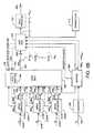
- FIG. 4is a diagram presenting further detail of how the input data streams having video, audio, or data information are combined before encoding, modulation and transmission to the satellite 108.
- uncompressed data streams D 1 - D n(labeled 410A-412N) are provided to the input 412A-412B) to encoders 402A-402N, respectively.
- the encoders 402A-402Nare MPEG encoders which compress the input data streams D 1 - D n according to one or more of the standards (MPEG-1 or MPEG-2). Other compression techniques can be used as well.
- the output 414A-414N of the encoders 402A-402Nis each provided to a data input 416A-416N of a statistical multiplexer 404.
- the statistical multiplexer 404manages the presentation of the encoder outputs at the output of the statistical multiplexer 404.
- thisis accomplished by supervising the encoding of the data signals D 1 , D 2 , ⁇ , D n into compressed data signals d 1 , d 2 , ⁇ , d n , accepting the compressed data signals d 1 , d 2 , ⁇ , d n from the encoders 402A-402N, and multiplexing the compressed data signals d 1 , d 2 , ⁇ , d n to provide an output signal 422 at an output 424
- This output signal 424is then encoded, modulated, and uplinked to the satellite 108.
- Each of the encoders 402A-402Ncompresses the input data D 1 - D N according to a maximum data rate that is negotiated with the statistical multiplexer 404.
- the first encoder 402Aexamines the incoming data stream D 1 to determine how much the data stream can be compressed without compromising the excessive data loss. For example, if encoder 402A is tasked with compressing the incoming data stream D 1 according to an MPEG-2 encoding scheme, the encoder 402A examines data characteristics of the incoming data stream D 1 such as the scene complexity and temporal variation to estimate the maximum data rate that will be required in the compressed data signal d 1 to reproduce the input data stream according to pre-established standards.
- the encoder 402Athen transmits this information, a "bandwidth" request BW R 1 , to the statistical multiplexer 404 (hereinafter, the term “bandwidth” will be used interchangeably with the phrases “data rate” or “throughput” and refers to the rate at which data may be transmitted over the particular data transmission channel).
- the statistical multiplexer 404balances this bandwidth request with similar requests from the other encoders (402B-402N) according to a statistical multiplexer equation 406 having parameters 408 that can be input to the statistical multiplexer 404 at a first control input 418.
- the statistical multiplexer 404generates an optimal allocation of bandwidth among the encoders 402A-402N in order to meet a target bandwidth B T (which may be specified at a second control input 420) for the multiplexed signal output signal 422 at the output 424 of the statistical multiplexer 404.
- a target bandwidth B Twhich may be specified at a second control input 420
- the target bandwidth level B Tis typically predetermined and remains constant, and may be less than or equal to the transmission bandwidth BW X .
- a bandwidth value ( BW G 1 )is granted to the first encoder 402A, and thereafter, the first encoder 402A compresses the incoming data stream D 1 to assure that the data stream presented at the encoder 402A output, does not exceed the granted data rate or bandwidth value BW G 1 .
- the bandwidth requested by the encoder 402A BW R 1 and subsequently granted by the statistical multiplexer 404 BW G 1is often greater than what is required to reproduce the input data stream D 1 within acceptable standards.
- the encoder 402Atypically inserts null data (such as zero video data) so that the data rate of the data stream d 1 output from the encoder 402A is a value consistent with the bandwidth BW G 1 granted by the statistical multiplexer 404.
- the need to insert zero video datacan arise in several situations.
- One such situationoccurs, when the estimate of the bandwidth required by the encoder 402A is in error (i.e. due to scene changes and other signal changes that are difficult or impossible to predict).
- Another situation in which zero video data is insertedarises because the value of the granted bandwidth BW G 1 and/or the requested bandwidth BW R 1 is not continuously variable, but rather selected from a finite number of available values. For example, if the granted bandwidth BW G 1 is a value often mega bits per second (10 MBPS), and the encoder can only compress the data to produce a 9 MBPS data stream or an 11 MBPS data stream, the encoder 402A will encode the data to not exceed the 9 MBPS rate, and insert null data for the remaining data.
- the granted bandwidth BW G 1is a value often mega bits per second (10 MBPS)
- the encoder 402Awill encode the data to not exceed the 9 MBPS rate, and insert null data for the remaining data.
- the need to insert zero video datacan also arise as follows.
- a minimum ratecan be imposed per video channel.
- a limitis set such that for any given sequence of images, a minimum bandwidth will be allocated.
- the sequence of imagescan be encoded highly efficiently, using less than the minimum bandwidth imposed per channel.
- the encoderpads the elementary stream with zeroes at the end of each picture element. This typically occurs with low complexity still or limited-motion images, such as slides or images of "talking heads.”
- the signal output from the encoder 402Acan be represented as d 1 + N E 1 wherein d 1 represents the compressed version of the input data stream D 1 (which would require an actual bandwidth BW A 1 ⁇ BW G 1 ), and N E 1 represents the zero video data added to the compressed input data stream so that the output of the encoder 402A is provided at the granted data rate BW G 1 .
- the bandwidth used to transmit the zero video data N E 1is referred to as encoder overhead bandwidth BW OE 1 .
- BW A 1 +BW OE 1BW G 1 .
- the statistical multiplexer 404specifies the bandwidth or data rate for the output signals from the encoders 402A-402N (as BW G 1 , BW G 2 , ⁇ , BW G n ) to meet the target bandwidth BW T
- the target bandwidth BW Tis typically underspecified (not set to the maximum transmission bandwidth BW x ) to provide overhead BW OSM to provide for unexpected changes such as changes in transmission bandwidth BW x
- the output data stream provided by the statistical multiplexer 404also typically includes null packets (e.g. null packets 310) so that the actual data rate of the output signal BW SM is less than the target data rate BW T .
- the output of the statistical multiplexerincludes a signal having compressed input data and null data according to the following relation: ( d 1 + N E 1 )+( d 2 + N E 2 )+ ⁇ +(d n + N E n ) + N SM wherein N SM represents the null packets added by the statistical multiplexer 404.
- FIG. 5is a diagram depicting one embodiment of a null packet replacer 500.
- the illustrated embodimentallows the substitution of auxiliary data D A 502 for the null data N E 1 + N E 2 + ⁇ + N E n + N SM (which typically represents between one to five percent of the available bandwidth BW X ). It also allows control of the processes taking place in the statistical multiplexer 404 to permit the substitution of non-opportunistic auxiliary data 502, if desired.
- Auxiliary data D Ais provided to an auxiliary multiplexer 508 where the null data D A is inserted in the place of null data packets in the output stream N E 1 + N E 2 + ⁇ + N E n + N SM provided at the output 424 of the statistical multiplexer 404.
- the auxiliary data D Ais stored in a buffer 506 communicatively coupled between the auxiliary data input data stream 502 and the auxiliary multiplexer 508 before being provided to the auxiliary multiplexer 508. Storage of auxiliary data D A in the buffer 506 permits the auxiliary data D A to be delayed for a short period of time before substitution for null data in the data stream output from the statistical multiplexer.
- the incoming datacan be optionally compressed and/or encoded by an encoder 504 before temporary storage in the buffer 506 (or, if a buffer 506 is not provided, the auxiliary data D A can be transmitted directly from the encoder 504 to the auxiliary multiplexer 508).
- auxiliary data D Ais presented to the buffer 506 at a rate exceeding that which the data can be inserted into the output data stream, the amount of data stored in the buffer 506 will approach the memory capacity of the buffer, thus decreasing the amount of unused memory in the buffer 506 and increasing the "fullness" of the buffer 506 increases.
- this informationis provided from the buffer 506 to the auxiliary multiplexer 508.
- the auxiliary multiplexer 508uses this information to command the statistical multiplexer 404 to control the process used in multiplexing the data streams from encoders 402A-402N, thereby reducing (or increasing) the bandwidth or data rate requirements for the data presented at the output of the statistical multiplexer 404.
- the auxiliary multiplexer 508can command the statistical multiplexer 404 to combine the signals from each of the encoders 402A-402 in a way that reduces the data rate of the data d 1 + d 2 + ⁇ + d n presented at the output of the statistical multiplexer 404, as described further below.
- the auxiliary multiplexer 508may command the statistical multiplexer 404 to combine the signals from the encoders 402A-402N in such a way that increases the data rate of the data d 1 + d 2 + ⁇ + d n presented at the output of the statistical multiplexer 404 when the buffer 506 is below a desired value.
- the "fullness" of the buffer 506can be used adaptively to assure that the output data stream from the auxiliary multiplexer has virtually no null data packets.
- the buffer 506can also accept some or all of the data from the encoders 402A-402N, and provide the data to the auxiliary multiplexer 508.
- the auxiliary multiplexer 508can control the statistical multiplexer in many ways to permit the introduction of auxiliary data D A .
- the auxiliary multiplexer 508provides a command to alter or add to the statistical multiplexer equation 406 (or to change the statistical multiplexer equation 406 itself), essentially making adding a "proxy" for the new data in the statistical multiplexer 404 so that it may negotiate for the auxiliary data D A like any other of the data sources.
- This techniquecan provide increased null packets for inserting auxiliary data D A on a rapid basis (in the order of a frame or so).
- the auxiliary multiplexer 508may also command the statistical multiplexer 404 to combine the data from encoders 402A-402N to meet a different (reduced or increased) target bandwidth requirement BW T .
- auxiliary multiplexer 508substitutes auxiliary data D A for null data N E 1 + N E 2 + ⁇ + N E n + N SM according to a process defined at least in part according to null packet replacement parameters 512.
- the null packet replacement parametersinclude, for example:
- the Prioritymay be expressed as a rank.
- the each source of auxiliary data D Ais assigned one or more of the foregoing parameters (the data streams entering the encoders 402A-402 may also be assigned one or more of these parameters).
- the foregoing valuesare used by the auxiliary multiplexer 508 to determine when there is sufficient null data N E 1 + N E 2 + ⁇ + N E n + N SM to allow substitution of the auxiliary data D N .
- the auxiliary multiplexercan command the statistical multiplexer 404 to provide additional null packets (via manipulation of the statistical multiplexer equation 406 or target bandwidth BW T ).
- a master program guidewhich provides information regarding the timing and content of video programs is transmitted.
- This informationwas typically transmitted as one of the data streams D 1 -D n and regarded as a constant bit rate (CBR) data stream in the order of 100Kb/s.
- CBRconstant bit rate
- a drivermay be inserted between the source of MPG data and statistical multiplexer 404 to carefully maintain an average data rate for the MPG data stream of about 80% of the CBR rate, while temporarily storing excess data in a buffer.
- the average delay before the MPG data is provided at the output of the auxiliary multiplexer 508is approximately 1 second and the maximum delay could be just under 2 seconds while still satisfying the requirement to meet the average rate of 80 Kb/s.
- the MPG datacan be inserted into the data stream output from the statistical multiplexer 404 even though the instantaneous null data rate is not known in advance. However, the instantaneous null data rate must be higher than the average data rate of the auxiliary data stream(s).
- the auxiliary multiplexer 404can analyze the auxiliary data D A according to the parameters described above, and drop non essential data or transfer it to long term storage at a more temporally distant time.
- the MPG data stream described aboveis typically organized as a carousel of data that is repeated every few seconds. If the transmission of the data in the carousel normally took 4 seconds, one wrap of the carousel could be dropped if there are insufficient null packets output from the statistical multiplexer 404. Further, the data requirements for the MPG could be reduced by 50% of the average rate by dropping every other transmission of the carousel data. By assigning a priority value for all of the auxiliary data services (or, for that matter, all of the data services, including data streams D 1 -D n , it is possible to temporarily lose non-essential descriptive information while protecting critical data.
- FIGs. 6A and 6Billustrates a post processor 510 that, in conjunction with any of the foregoing elements, can be used to insert auxiliary data D A before transmission, while still remaining below the maximum transmission data rate BW x .
- the post processor 510can be communicatively coupled to the output of the auxiliary multiplexer 508 as shown in FIG. 6A or communicatively coupled between the statistical multiplexer 404 and the auxiliary multiplexer 508 as shown in FIG. 6B.
- post processingis performed on the data stream ( d 1 + N E 1 ) + ( d 2 + N E 2 ) + ⁇ + (d n + N E n ) + N SM from the output of the statistical multiplexer 418 to further compress the data streams d 1 -d n .
- the degree of further compressioncan be controlled either by the auxiliary multiplexer 508, or directly by a signal from the buffer 506 regarding buffer fullness.
- the encoders 402A-402Nare MPEG encoders, and the process of decoding the encoded data streams d 1 -d n and recoding them may take into account the activity and general picture quality via the m-quant value inherent in such encoding/decoding schemes. In this embodiment, examination of this m-quant value can permit a determination as to whether further compression is permissible, and the extent of such further compression can be made.
- post processingis performed on the data signal emanating from the output of the auxiliary multiplexer 508.
- the signal emanating from the output of the auxiliary multiplexer 508 d 1 + d 2 + ⁇ +d n +d Acan have a throughput that exceeds BW x because the further compression provided by the post processor 510 reduces the throughput requirement back to a value that is equal to or less than BW x .
- FIG. 7is a diagram depicting exemplary method steps that can be used to practice the present invention.
- a statistically multiplexed data stream having null datais accepted, as shown in block 702.
- Auxiliary data D Ais buffered and the amount of null data in the statistically multiplexed data stream is controlled to provide sufficient null data to permit the substitution of the auxiliary data D A in the statistically multiplexed data stream. This is shown in block 704. At least a portion of the auxiliary data D A is substituted for the null data in the statistically multiplexed data stream.
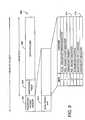
- FIG. 8is a flow chart presenting illustrative method steps which can be used to identify null and zero data packets for replacement with auxiliary data packets.
- the auxiliary multiplexer 508looks at the identifies data packets having null data N E 1 + N E 2 + ⁇ + N E n and zero data N SM . This can be performed by examining the output of the statistical multiplexer 404, or the output of each of the encoders 412. As shown in blocks 802 and 804, packets having zero data N SM can be identified by examination of the first packet segment 320 or header for an identifier indicating that the data packet includes only null data.
- the packetis determined to be a null packet, and auxiliary data can be substituted for the payload of that data packet, as shown in block 806. If the PID 912 does not match the value assigned to a null packet, the packet is further examined.
- FIG. 9is a diagram presenting a depiction of an exemplary transport packet 902 according to the MPEG-2 standard.
- the transport packetincludes a header 904, an optional adaptation field 906 and a data payload section 908.
- the transport header 904includes a synchronization word 910 and a plurality of bit assignments including those which are assigned to the PID 912 to identify the packet and a continuity indicator 914.
- Zero packets(packets with null data inserted by encoders 412 in the data payload section 908) are more difficult to detect, because the header (904 and/or 320) of the zero data packet may be identical to the header of a data packet with video or audio data.
- Zero packetscan be identified by fully parsing the MPEG data stream and identifying unnecessary zero bytes for elimination. However, this technique is computationally intensive. In one embodiment of the present invention, the data packets are screened to identify those which might be candidates for having sufficient null data to permit substitution of auxiliary data.
- nextbits() function(defined in ITU-T H.262 , in paragraphs 6.2.4 and 5.2.2, which references are hereby incorporated by reference) which permits comparison of a bit string with the next bits to be decoded in the bitstream).
- Some encoding schemes used by the encoders 402chop data asynchronously across data packets. All current MPEG encoders, for example, chop data asynchronously into transport packets. Thus, a particular data value or set of related data values may be transmitted by more than one data packet (although both will have the same PID). Consequently, to be sure that the current packet under examination (which may have all zeros, but has not been assigned a PID indicating it has nothing but null data) is a packet that is transmitting a data value consisting of only null data, it is necessary to examine the temporally adjacent (e.g. previous) packet having the same PID.
- the logic shown in FIG. 8assume that two data elements are available for each packet (and PID) under examination.
- the firstis a flag (STATE) for each packet (according to the packet PID).
- STATEflag
- the initial value for the STATE flagis zero.
- the second element of informationis a static table that defines which packets (according to the packet's PID) are video and hence likely to include null data. This data can be obtained from an MPEG PMT or from a configuration table that is external to the data stream under examination.
- block 808determines whether the packet under consideration is a packet of a type that is likely to have null data, such as a video packet (although in other embodiments, null data may be included in audio or other data). This determination can be made, for example, by examining the PID of the packet and comparing the PID to a look up table. If the packet is of a type that is not likely to have null data, the data packet under examination is not a candidate for substitution, and auxiliary data is not substituted into the packet, as shown in block 822. The next packet is be examined, as shown in block 826.
- Block 810tests a STATE flag that is associated with the PID for the packets.
- the STATE flagdescribes the following state conditions:
- NB ⁇ 3represents the smallest value when it is known that the start codes following stuffing are packet aligned (typically true).
- NB ⁇ 5is the smallest value when it is not known that the start codes following stuffing are not packet aligned.
- the final determination as to whether the current packet includes zero data or notis deferred until examination of the next data packet with the same PID.
- auxiliary datacan be substituted for zero data
- two data packetsare examined: (1) the current data packet, and (2) a data packet having the same PID and temporally adjacent to the current data packet. If data packet (2) includes at least a number NB consecutive zero data values and data packet (1) includes all zero data values, data packet (1) is a candidate to have at least a portion of the auxiliary data D A substituted for the data payload.
- the different substitution schemesmay be implemented as appropriate for the coding methods employed by the encoders 402 and the statistical multiplexer 404.
- the methodmay be modified so that non-zero null data padding may be recognized as well, or so that NB equals a different integer.
- auxiliary multiplexer 508examines the incoming data stream, determines what sort of protocol was used to pad each data stream with null data and/or to multiplex different data streams together, and adaptively modifies the algorithm used to substitute auxiliary data for the null data according to the determined protocol.
- the auxiliary multiplexer 404may substitute auxiliary data for null data inserted by encoders 402 using different padding protocols and schemes (e.g. a system in which encoder 402A is an MPEG-2 compliant encoder, but encoder 402B is an encoder complying to an entirely different encoding standard).
- substitution of data for null data in zero data packets or null data packetsmay require regeneration of the continuity indicators 914 in the header 914 of the transport packets 902 of the data stream to maintain the correct syntax of the transport data packet.
- the auxiliary multiplexer 504also provides additional functionality to make packet-by-packet decisions regarding when insertion of auxiliary data for null data is permitted.
- the auxiliary multiplexer 504may impose a maximum data rate at which data from the buffer 506 can be placed in the output data stream via the use of a governor that imposes a minimum packet spacing for each stream. If the minimum number of packets have not passed since the last data packet was applied, the governor restricts the data from being read out of the buffer 506 and provided at the output of the auxiliary multiplexer 508.
- a packet-by-packet priority systemcan be employed to select which of the plurality of data packets available at the buffer 506 are to be restricted by the governor and/or to be read and provided at the output before other data packets.
- the priorities assigned to particular data streamsmay also be dynamic in that they may change over time to assign higher priorities to auxiliary data streams when required. For example, a priority counter may be incremented each time an auxiliary datastream/packet is passed by for data insertion, moving the data stream/packet up in relative priority compared to other datastreams/packets. The datastream/packet with the highest current priority is then designated to replace the next available null/zero data packet.
Landscapes
- Engineering & Computer Science (AREA)
- Signal Processing (AREA)
- Multimedia (AREA)
- Computer Networks & Wireless Communication (AREA)
- Compression Or Coding Systems Of Tv Signals (AREA)
- Data Exchanges In Wide-Area Networks (AREA)
- Television Systems (AREA)
- Time-Division Multiplex Systems (AREA)
- Two-Way Televisions, Distribution Of Moving Picture Or The Like (AREA)
Abstract
Description
- Null Data:
- "Null data" refers generically to data that includes no information,and includes all of the data types described below.
- Null packet:
- A null packet is a packet that has an identifier indicating that thepacket includes only null data. In the illustrated example, nullpackets include those with a packet identifier (PID) of 8191.
- Zero video data:
- Padding in an elementary data stream that includes no useful data.Zero video data can be located before every program element suchas the program start code, slice code, or sequence header.
- Zero video packet:
- An entire transport packet that contains nothing but zero videodata. Zero video packets are different from NULL packets in thatNULL packets are clearly identified by a packet identifier.
- BWMIN - The minimum rate required to keep the data service active;-
- BWMAX - The maximum sustained data rate of the data service;
- BWAVG - The nominal or guaranteed rate over a time periodtper;
- tper - The time period used to determine the average rateBWAVG. The valueoftper can be used to infer that the data stream can be delayed by a nominaland maximum amount of time; and
- Priority - A priority of the data service compared to the other services.
Claims (28)
- An apparatus for adding auxiliary dataDA to an output data stream,comprising:a statistical multiplexer having a plurality of inputs including a first input, and anoutput providing the output data stream;a first encoder, having an output communicatively coupled to the a first statisticalmultiplexer input, the first encoder for compressing a first data streamD1 according to afirst actual data rateBWA
1 that is less than or equal to a first granted data rateBWG1 granted by the statistical multiplexer in response to a requested data rateBWR1 fromthe encoder, the difference between the first actual data rateBWA1 and the first granteddata rateBWG1 defining an encoder overhead rateBWOE1 such thatBWG1 -BWA1 = BWOE1 ≥ 0, the first encoder having an output including an compressedversion of the first data streamd1 provided at the actual data rateBWA1 and encoder nulldataNE1 at the overhead rateBWO1 ; andan auxiliary multiplexer, communicatively coupled to the statistical multiplexer, forsensing encoder null dataNE and for substituting at least a portion of the auxiliary dataDAfor the encoder null dataNE. - The apparatus of claim 1, wherein the auxiliary multiplexer iscommunicatively coupled between the output of the encoder and the input of the statisticalmultiplexer.
- The apparatus of claim 1, wherein the auxiliary multiplexer iscommunicatively coupled to the output of the statistical multiplexer.
- The apparatus of claim 3, further comprising a buffer, communicativelycoupled to the auxiliary multiplexer, the buffer for buffering the auxiliary data.
- The apparatus of claim 4, wherein the auxiliary multiplexer substitutes theauxiliary data according to an unused memory of the buffer.
- The apparatus of claim 3, wherein the auxiliary multiplexer further sensesstatistical multiplexer null dataNSM and substitutes at least a portion of the auxiliary datafor the multiplexer null dataNSM.
- The apparatus of claim 3, wherein:the statistical multiplexer manages the presentation of the first encoder outputaccording to a first command input describing a target data rate of the output data streamBT; andthe auxiliary multiplexer is communicatively coupled to the statistical multiplexerfirst input to command a change the target data rate of the output data streamBT.
- The apparatus of claim 7, further comprising a buffer, communicativelycoupled to the auxiliary multiplexer, the buffer for buffering the auxiliary data, wherein theauxiliary multiplexer changes the target data rate according to an unused memory of thebuffer.
- The apparatus of claim 7, wherein the auxiliary multiplexer changes thetarget data rate according to one or more auxiliary data parameters selected from thegroup comprising:a minimum auxiliary data rateBWMIN;a maximum auxiliary data rateBWMAX;a nominal auxiliary data rateBWAVG measured over a time periodtper; anda priority.
- The apparatus of claim 7, wherein the change in the target data rate of theoutput data is commanded to decrease the target rate of the output data streamBT topermit the substitution of auxiliary dataDA for the multiplexer null dataNSM.
- The apparatus of claim 7, wherein:the auxiliary multiplexer further senses statistical multiplexer null dataNSM andsubstitutes at least a portion of the auxiliary data for the multiplexer null dataNSM; andthe change in the target data rate of the output data is commanded to decrease thetarget rate of the output data streamBT to permit the substitution of auxiliary dataDA fordata selected from the group comprising the encoder null dataNE
1 and the multiplexernull dataNSM. - The apparatus of claim 9, wherein the auxiliary data is added at a prespecifiedminimum auxiliary data rate.
- The apparatus of claim 3, further comprising:wherein the statistical multiplexer allocates data presented at the plurality of inputsto the statistical multiplexer output according to a statistical multiplexer second commandinput; anda second encoder, having an output communicatively coupled to the a firststatistical multiplexer input, the first encoder for compressing a first data streamD2according to a first actual data rateBWA2 that is less than or equal to a first granted datarateBWG2 granted by the statistical multiplexer [in response to a requested data rateBWR
2 from the encoder, the difference between the first actual data rateBWA21 and thefirst granted data rateBWG2 defining an encoder overhead rateBWO2 such that
BWG1 -BWA1 =BWO2 ≥ 0, the first encoder having an output including an compressedversion of the first data stream provided at the actual data rateBWA21 and encoder nulldataNE1 at the overhead rateBWO2 , the second encoder having an output;
wherein the auxiliary multiplexer is communicatively coupled to the statisticalmultiplexer second input to command a change in the allocation of the data presented atthe plurality of inputs to the statistical multiplexer output. - The apparatus of claim 13 wherein the auxiliary multiplexer changes theallocation of the data presented at the plurality of inputs to the statistical multiplexeroutput according to an unused memory of a buffer communicatively coupled to theauxiliary multiplexer, the buffer for buffering the auxiliary data.
- The apparatus of claim 14, wherein the multiplexer changes the allocationof the data presented at the plurality of inputs to the statistical multiplexer outputaccording to an unused memory of the buffer.
- A method of adding auxiliary dataDA to a data stream, comprising thesteps of:accepting a statistically multiplexed data stream having null data; andsubstituting at least a portion of the auxiliary dataDA for the null data in thestatistically multiplexed data stream.
- The method of claim 16, wherein the auxiliary dataDA is non-opportunisticdata.
- The method of claim 17, further comprising the step of:buffering the auxiliary dataDA until there is sufficient null data to permit thesubstitution of the at least some of the auxiliary dataDA in the statistically multiplexeddata stream.
- The method of claim 18, further comprising the step of:controlling an amount of the null data in the statistically multiplexed data toprovide sufficient null data to permit the substitution of at least some of the auxiliary dataDA in the statistically multiplexed data stream.
- The method of claim 19 wherein the amount of null data is controlledaccording to a relationship between an amount of the buffered auxiliary dataDA and acapacity of a buffer storing the buffered data.
- The method of claim 19, wherein the null data comprises statisticalmultiplexer null dataNSM.
- The method of claim 20, wherein the statistically multiplexed data stream isstatistically multiplexed to a throughput less than or equal to a target throughput valueBWT, and the step of controlling an amount of null data in the statistically multiplexeddata comprises the step of altering the target throughput valueBWT.
- The method of claim 19, wherein the null data comprises encoder null dataNE.
- The method of claim 23, wherein the statistically multiplexed data stream isstatistically multiplexed according to a statistical multiplexer equation, and the step ofcontrolling an amount of null data in the statistically multiplexed data according to arelationship between the amount of buffered auxiliary dataDA and a capacity of a bufferstoring the buffered data comprises the step of altering the statistical multiplexer equation.
- The method of claim 19, further comprising the step of:examining the auxiliary dataDA for non-essential data; andeliminating the non-essential data from the auxiliary dataDA before substitutingthe auxiliary dataDA for the null data in the statistically multiplexed data stream.
- The method of claim 19, wherein the step of amount of null data in thestatistically multiplexed data is controlled according to a parameter set describing theauxiliary dataDA, including:a minimum throughput required to keep the data service activeBWMIN;a maximum sustained throughput of the data serviceBWMAX; anda nominal or guaranteed rate over a time periodBWAVG.
- The method of claim 16, wherein the data stream comprises a set of datapackets all having a packet ID including a first data packet and a second data packettemporally adjacent the first data packet, and the step of substituting at least a portion ofthe auxiliary dataDA for the null data in the statistically multiplexed data streamcomprises the steps of:substituting at least a portion of the auxiliary dataDA for the data in the seconddata packet if the first data packet includes at least a numberNB consecutive zero datavalues and the second data packet includes all zero data values.
- A system for transmitting auxiliary dataDA packetized satellite signal,comprising:a statistical multiplexer having a plurality of inputs including a first input, and anoutput providing an output data stream;a first encoder, having an output communicatively coupled to the a first statisticalmultiplexer input, the first encoder for compressing a first data streamD1 according to afirst actual data rateBWA
1 that is less than or equal to a first granted data rateBWG1 granted by the statistical multiplexer in response to a requested data rateBWR1 fromthe encoder, the difference between the first actual data rateBWA1 and the first granteddata rateBWG1 defining an encoder overhead rateBWOE1 such thatBWG1 - BWA1 = BWOE1 ≥ 0, the first encoder having an output including an compressedversion of the first data streamd1 provided at the actual data rateBWA1 and encoder nulldataNE1 at the overhead rateBWO1 ; andan auxiliary multiplexer, communicatively coupled to the statistical multiplexer, forsensing encoder null dataNE and for substituting at least a portion of the auxiliary dataDAfor the encoder null dataNE;a modulator communicatively coupled to the auxiliary multiplexer, for modulatingthe output data stream;a transmitter, communicatively coupled to the modulator for transmitting theoutput data stream; anda transponder, for receiving the transmitted modulated output data stream and forretransmitting the received output data stream to a subscriber.
Applications Claiming Priority (2)
| Application Number | Priority Date | Filing Date | Title |
|---|---|---|---|
| US10/038,174US7376159B1 (en) | 2002-01-03 | 2002-01-03 | Exploitation of null packets in packetized digital television systems |
| US38174 | 2002-01-03 |
Publications (3)
| Publication Number | Publication Date |
|---|---|
| EP1326355A2true EP1326355A2 (en) | 2003-07-09 |
| EP1326355A3 EP1326355A3 (en) | 2006-03-15 |
| EP1326355B1 EP1326355B1 (en) | 2009-03-04 |
Family
ID=21898470
Family Applications (1)
| Application Number | Title | Priority Date | Filing Date |
|---|---|---|---|
| EP03000152AExpired - LifetimeEP1326355B1 (en) | 2002-01-03 | 2003-01-03 | Exploitation of null packets in packetized digital television systems |
Country Status (5)
| Country | Link |
|---|---|
| US (2) | US7376159B1 (en) |
| EP (1) | EP1326355B1 (en) |
| JP (1) | JP4414134B2 (en) |
| DE (1) | DE60326404D1 (en) |
| ES (1) | ES2321702T3 (en) |
Cited By (8)
| Publication number | Priority date | Publication date | Assignee | Title |
|---|---|---|---|---|
| WO2006021534A1 (en)* | 2004-08-23 | 2006-03-02 | Siemens Aktiengesellschaft | Method for efficiently processing data packets, associated transmission protocol layer, communication terminal and network components comprising said type of transmission protocol layer |
| WO2007060577A1 (en)* | 2005-11-22 | 2007-05-31 | Koninklijke Philips Electronics N.V. | Method and apparatus for download in digital broadcasting system |
| EP2046063A1 (en)* | 2007-10-02 | 2009-04-08 | Alcatel Lucent | Method for rate control of multimedia streams and apparatus for performing this method |
| EP1924016A3 (en)* | 2006-11-15 | 2011-11-16 | Rohde & Schwarz GmbH & Co. KG | Optimized management of real-time transmission capacity in a digital broadcast system |
| WO2012069088A1 (en)* | 2010-11-26 | 2012-05-31 | Telefonaktiebolaget L M Ericsson (Publ) | Method and device for buffering data for multiplexing |
| EP2523370A3 (en)* | 2011-05-11 | 2013-10-09 | Comcast Cable Communications, LLC | Method and apparatus for managing broadcast data transmission resources, comprising allocation of content data and application data related to the content data |
| EP2833641A4 (en)* | 2012-03-26 | 2015-08-12 | Mitsubishi Electric Corp | VIDEO TRANSMITTER / RECEIVER SYSTEM, VIDEO TRANSMITTING METHOD, AND TRANSMITTING DEVICE |
| EP3160146A4 (en)* | 2014-06-20 | 2017-11-01 | Sony Corporation | Transmission device, transmission method, reception device, and reception method |
Families Citing this family (24)
| Publication number | Priority date | Publication date | Assignee | Title |
|---|---|---|---|---|
| JP2004015114A (en)* | 2002-06-03 | 2004-01-15 | Funai Electric Co Ltd | Digital broadcast recording device and digital broadcast system provided with the same |
| JP4391091B2 (en)* | 2003-01-17 | 2009-12-24 | ソニー株式会社 | Information transmission method, information transmission device, information recording method, information recording device, information reproducing method, information reproducing device, and recording medium |
| KR100624786B1 (en)* | 2004-01-29 | 2006-09-19 | 엘지전자 주식회사 | Server system to communicate via wireless network |
| US7602820B2 (en) | 2005-02-01 | 2009-10-13 | Time Warner Cable Inc. | Apparatus and methods for multi-stage multiplexing in a network |
| US7948878B2 (en)* | 2005-02-07 | 2011-05-24 | British Telecommunications Plc | Policing networks |
| US8189786B2 (en)* | 2005-05-25 | 2012-05-29 | Zenith Electronics Llc | Encryption system |
| US8144868B2 (en)* | 2005-05-25 | 2012-03-27 | Zenith Electronics Llc | Encryption/decryption of program data but not PSI data |
| US7889765B2 (en)* | 2005-11-30 | 2011-02-15 | Time Warner Cable Inc. | Apparatus and methods for utilizing variable rate program streams in a network |
| FI120175B (en)* | 2006-10-27 | 2009-07-15 | Tellabs Oy | Transmission of digital information in a data transmission network with frame transmission |
| US8625607B2 (en) | 2007-07-24 | 2014-01-07 | Time Warner Cable Enterprises Llc | Generation, distribution and use of content metadata in a network |
| US20090028142A1 (en)* | 2007-07-25 | 2009-01-29 | Schmidt Brian K | Streaming data content in a network |
| US8179982B2 (en)* | 2008-04-22 | 2012-05-15 | Samsung Electronics Co., Ltd. | Transmitting additional information in the headers of encapsulating data packets in mobile/handheld (M/H) DTV signals |
| JP5195674B2 (en)* | 2009-07-13 | 2013-05-08 | 富士通株式会社 | Image encoding device |
| KR101129900B1 (en) | 2009-08-06 | 2012-03-28 | 한국방송공사 | Dmb tx/rx apparatus and method for transmitting supplement data by idle band of video service |
| US8929710B2 (en) | 2010-11-01 | 2015-01-06 | Todd E. Fitzsimmons | System and method for time shifting at least a portion of a video program |
| US20140098852A1 (en)* | 2012-10-05 | 2014-04-10 | Samsung Display Co., Ltd. | Compression bandwidth overflow management using auxiliary control channel |
| US9781488B2 (en)* | 2015-07-30 | 2017-10-03 | Adi Rozenberg | Controlled adaptive rate switching system and method for media streaming over IP networks |
| KR102380285B1 (en)* | 2015-10-14 | 2022-03-30 | 삼성전자주식회사 | Method and apparatus for transmitting and receiving packet in multimedia system |
| JP2017162048A (en)* | 2016-03-08 | 2017-09-14 | 三菱電機株式会社 | Buffering system |
| US10306329B2 (en) | 2016-11-30 | 2019-05-28 | The Directv Group, Inc. | Facilitating mixed service use of bonded satellite transponders |
| CN110198474B (en)* | 2018-02-27 | 2022-03-15 | 中兴通讯股份有限公司 | Code stream processing method and device |
| US11323758B1 (en)* | 2019-12-12 | 2022-05-03 | Amazon Technologies, Inc. | Lossless transport stream compression from constant bitrate to variable bitrate to constant bitrate |
| US11379595B2 (en)* | 2020-01-16 | 2022-07-05 | EMC IP Holding Company LLC | Zero-knowledge protection for side channels in data protection to the cloud |
| US20250008172A1 (en)* | 2023-06-27 | 2025-01-02 | Microsoft Technology Licensing, Llc | Full motion video (fmv) routing in one-way transfer systems |
Family Cites Families (70)
| Publication number | Priority date | Publication date | Assignee | Title |
|---|---|---|---|---|
| US3627914A (en) | 1969-09-04 | 1971-12-14 | Central Dynamics | Automatic television program control system |
| FR2181593B1 (en) | 1972-04-26 | 1974-10-18 | Ibm France | |
| DE3735421A1 (en)* | 1987-10-20 | 1989-05-11 | Deutsche Forsch Luft Raumfahrt | METHOD FOR REDUCING AIRCRAFT OVERFLIGHT NOISE WITH A PROPELLER DRIVED BY A PISTON ENGINE |
| US5404315A (en) | 1991-04-30 | 1995-04-04 | Sharp Kabushiki Kaisha | Automatic sound gain control device and a sound recording/reproducing device including arithmetic processor conducting a non-linear conversion |
| US5642437A (en) | 1992-02-22 | 1997-06-24 | Texas Instruments Incorporated | System decoder circuit with temporary bit storage and method of operation |
| US5337041A (en) | 1992-04-13 | 1994-08-09 | Lorri Friedman | Personal safety guard system for stray person or pet |
| US5363147A (en) | 1992-06-01 | 1994-11-08 | North American Philips Corporation | Automatic volume leveler |
| US5831681A (en) | 1992-09-30 | 1998-11-03 | Hudson Soft Co., Ltd. | Computer system for processing sound data and image data in synchronization with each other |
| CA2104753C (en) | 1992-10-29 | 1999-02-16 | Kotikalapudi Sriram | Bandwidth allocation, transmission scheduling, and congestion avoidance in broadband atm networks |
| US5579404A (en) | 1993-02-16 | 1996-11-26 | Dolby Laboratories Licensing Corporation | Digital audio limiter |
| US5729556A (en) | 1993-02-22 | 1998-03-17 | Texas Instruments | System decoder circuit with temporary bit storage and method of operation |
| ES2123013T5 (en) | 1993-03-22 | 2005-04-01 | Sony Deutschland Gmbh | A BROADCASTING SIGNAL RECEIVER. |
| CA2121151A1 (en) | 1993-04-16 | 1994-10-17 | Trevor Lambert | Method and apparatus for automatic insertion of a television signal from a remote source |
| US5461619A (en)* | 1993-07-06 | 1995-10-24 | Zenith Electronics Corp. | System for multiplexed transmission of compressed video and auxiliary data |
| US5448568A (en)* | 1994-04-28 | 1995-09-05 | Thomson Consumer Electronics, Inc. | System of transmitting an interactive TV signal |
| US5506844A (en)* | 1994-05-20 | 1996-04-09 | Compression Labs, Inc. | Method for configuring a statistical multiplexer to dynamically allocate communication channel bandwidth |
| US5625743A (en) | 1994-10-07 | 1997-04-29 | Motorola, Inc. | Determining a masking level for a subband in a subband audio encoder |
| US5666430A (en) | 1995-01-09 | 1997-09-09 | Matsushita Electric Corporation Of America | Method and apparatus for leveling audio output |
| US5650825A (en)* | 1995-03-31 | 1997-07-22 | Matsushita Electric Corporation Of America | Method and apparatus for sending private data instead of stuffing bits in an MPEG bit stream |
| US6026232A (en)* | 1995-07-13 | 2000-02-15 | Kabushiki Kaisha Toshiba | Method and system to replace sections of an encoded video bitstream |
| US5802068A (en)* | 1995-06-30 | 1998-09-01 | Nippon Steel Corporation | Multiplexing apparatus of a plurality of data having different bit rates |
| US5778077A (en) | 1995-09-13 | 1998-07-07 | Davidson; Dennis M. | Automatic volume adjusting device and method |
| US5966120A (en)* | 1995-11-21 | 1999-10-12 | Imedia Corporation | Method and apparatus for combining and distributing data with pre-formatted real-time video |
| US5686963A (en) | 1995-12-26 | 1997-11-11 | C-Cube Microsystems | Method for performing rate control in a video encoder which provides a bit budget for each frame while employing virtual buffers and virtual buffer verifiers |
| KR0165063B1 (en) | 1995-12-29 | 1999-02-01 | 정장호 | Statistical Multiplexer on Time Division Multiplexed Buses |
| US5822018A (en) | 1996-04-02 | 1998-10-13 | Farmer; James O. | Method and apparatus for normalizing signal levels in a signal processing system |
| US5898675A (en) | 1996-04-29 | 1999-04-27 | Nahumi; Dror | Volume control arrangement for compressed information signals |
| US6137834A (en) | 1996-05-29 | 2000-10-24 | Sarnoff Corporation | Method and apparatus for splicing compressed information streams |
| US5751723A (en) | 1996-07-01 | 1998-05-12 | Motorola, Inc. | Method and system for overhead bandwidth recovery in a packetized network |
| US5864557A (en) | 1996-09-25 | 1999-01-26 | Thomson Multimedia S.A. | Method and apparatus for opportunistically transferring data in a packet stream encoder |
| US6369855B1 (en) | 1996-11-01 | 2002-04-09 | Texas Instruments Incorporated | Audio and video decoder circuit and system |
| US5991812A (en) | 1997-01-24 | 1999-11-23 | Controlnet, Inc. | Methods and apparatus for fair queuing over a network |
| US5877821A (en) | 1997-01-30 | 1999-03-02 | Motorola, Inc. | Multimedia input and control apparatus and method for multimedia communications |
| TW384434B (en) | 1997-03-31 | 2000-03-11 | Sony Corp | Encoding method, device therefor, decoding method, device therefor and recording medium |
| JPH10284960A (en) | 1997-04-10 | 1998-10-23 | Matsushita Electric Ind Co Ltd | Audio level control method and playback device |
| KR19980076752A (en) | 1997-04-14 | 1998-11-16 | 윤종용 | Broadcast signal receiving method and receiving device for automatically switching screen and sound |
| US5987031A (en) | 1997-05-22 | 1999-11-16 | Integrated Device Technology, Inc. | Method for fair dynamic scheduling of available bandwidth rate (ABR) service under asynchronous transfer mode (ATM) |
| US6169807B1 (en) | 1997-10-04 | 2001-01-02 | Michael Sansur | Remote automatic audio level control device |
| EP0948787A1 (en) | 1997-10-28 | 1999-10-13 | Cellon France SAS | Improved audio reproduction arrangement and telephone terminal |
| UA56279C2 (en) | 1997-11-04 | 2003-05-15 | Джорджія Тек Ресерч Корпорейшн | System and method for maintaining time synchronization in a digital video network |
| US6169584B1 (en) | 1997-12-05 | 2001-01-02 | Motorola, Inc. | Automatic modulation control of sync suppressed television signals |
| US6047178A (en) | 1997-12-19 | 2000-04-04 | Nortel Networks Corporation | Direct communication wireless radio system |
| US6064676A (en) | 1998-01-14 | 2000-05-16 | Skystream Corporation | Remultipelxer cache architecture and memory organization for storing video program bearing transport packets and descriptors |
| US6389019B1 (en) | 1998-03-18 | 2002-05-14 | Nec Usa, Inc. | Time-based scheduler architecture and method for ATM networks |
| BR9909675A (en) | 1998-04-14 | 2001-10-30 | Hearing Enhancement Co Llc | Adjustable user volume control that accommodates listening |
| US6272131B1 (en) | 1998-06-11 | 2001-08-07 | Synchrodyne Networks, Inc. | Integrated data packet network using a common time reference |
| US7035278B2 (en) | 1998-07-31 | 2006-04-25 | Sedna Patent Services, Llc | Method and apparatus for forming and utilizing a slotted MPEG transport stream |
| GB2341745A (en) | 1998-09-10 | 2000-03-22 | Snell & Wilcox Ltd | Image encoding |
| US7068724B1 (en)* | 1999-10-20 | 2006-06-27 | Prime Research Alliance E., Inc. | Method and apparatus for inserting digital media advertisements into statistical multiplexed streams |
| US6298089B1 (en) | 1998-12-10 | 2001-10-02 | Viewgraphics, Inc. | Method for seamless and near seamless audio and non-video splicing of a digital transport stream |
| US6252848B1 (en) | 1999-03-22 | 2001-06-26 | Pluris, Inc. | System performance in a data network through queue management based on ingress rate monitoring |
| US6269855B1 (en)* | 1999-07-30 | 2001-08-07 | Magdi K. Elgendi | Multi-chamber pneumatic tire system |
| US6430233B1 (en) | 1999-08-30 | 2002-08-06 | Hughes Electronics Corporation | Single-LNB satellite data receiver |
| JP2001111969A (en) | 1999-10-06 | 2001-04-20 | Nec Corp | Ts packet data multiplexing method and ts packet data multiplexer |
| ATE439741T1 (en) | 1999-10-20 | 2009-08-15 | Samsung Electronics Co Ltd | METHOD AND APPARATUS FOR INSERTING DIGITAL MEDIA DISPLAYS INTO STATISTICAL MULTIPLEXED STREAMS |
| US6687247B1 (en) | 1999-10-27 | 2004-02-03 | Cisco Technology, Inc. | Architecture for high speed class of service enabled linecard |
| US6931370B1 (en) | 1999-11-02 | 2005-08-16 | Digital Theater Systems, Inc. | System and method for providing interactive audio in a multi-channel audio environment |
| JP2001169248A (en) | 1999-12-07 | 2001-06-22 | Matsushita Electric Ind Co Ltd | Digital audio level variable device |
| JP4300697B2 (en) | 2000-04-24 | 2009-07-22 | ソニー株式会社 | Signal processing apparatus and method |
| JP2001344905A (en) | 2000-05-26 | 2001-12-14 | Fujitsu Ltd | Data reproducing apparatus, method and recording medium |
| US6801886B1 (en)* | 2000-06-22 | 2004-10-05 | Sony Corporation | System and method for enhancing MPEG audio encoder quality |
| JP4055336B2 (en) | 2000-07-05 | 2008-03-05 | 日本電気株式会社 | Speech coding apparatus and speech coding method used therefor |
| JP4441839B2 (en)* | 2000-08-17 | 2010-03-31 | ソニー株式会社 | Statistical multiplexing system, statistical multiplexing control device, and statistical multiplexing method |
| US6429779B1 (en)* | 2000-12-26 | 2002-08-06 | Gino Petrillo | Telephone line monitoring and alarm apparatus |
| US20020146023A1 (en) | 2001-01-09 | 2002-10-10 | Regan Myers | Transport stream multiplexer utilizing smart FIFO-meters |
| US6510166B2 (en)* | 2001-03-31 | 2003-01-21 | Redback Networks, Inc. | Stuffing filter mechanism for data transmission signals |
| JP3601473B2 (en) | 2001-05-11 | 2004-12-15 | ヤマハ株式会社 | Digital audio compression circuit and decompression circuit |
| US20020173864A1 (en) | 2001-05-17 | 2002-11-21 | Crystal Voice Communications, Inc | Automatic volume control for voice over internet |
| US6765867B2 (en) | 2002-04-30 | 2004-07-20 | Transwitch Corporation | Method and apparatus for avoiding head of line blocking in an ATM (asynchronous transfer mode) device |
| US20040199933A1 (en) | 2003-04-04 | 2004-10-07 | Michael Ficco | System and method for volume equalization in channel receivable in a settop box adapted for use with television |
- 2002
- 2002-01-03USUS10/038,174patent/US7376159B1/ennot_activeExpired - Lifetime
- 2002-12-26JPJP2002378471Apatent/JP4414134B2/ennot_activeExpired - Fee Related
- 2003
- 2003-01-03ESES03000152Tpatent/ES2321702T3/ennot_activeExpired - Lifetime
- 2003-01-03DEDE60326404Tpatent/DE60326404D1/ennot_activeExpired - Lifetime
- 2003-01-03EPEP03000152Apatent/EP1326355B1/ennot_activeExpired - Lifetime
- 2008
- 2008-04-21USUS12/106,477patent/US7848364B2/ennot_activeExpired - Fee Related
Cited By (17)
| Publication number | Priority date | Publication date | Assignee | Title |
|---|---|---|---|---|
| WO2006021534A1 (en)* | 2004-08-23 | 2006-03-02 | Siemens Aktiengesellschaft | Method for efficiently processing data packets, associated transmission protocol layer, communication terminal and network components comprising said type of transmission protocol layer |
| WO2007060577A1 (en)* | 2005-11-22 | 2007-05-31 | Koninklijke Philips Electronics N.V. | Method and apparatus for download in digital broadcasting system |
| EP1924016A3 (en)* | 2006-11-15 | 2011-11-16 | Rohde & Schwarz GmbH & Co. KG | Optimized management of real-time transmission capacity in a digital broadcast system |
| EP2046063A1 (en)* | 2007-10-02 | 2009-04-08 | Alcatel Lucent | Method for rate control of multimedia streams and apparatus for performing this method |
| US9078017B2 (en) | 2010-11-26 | 2015-07-07 | Telefonaktiebolaget L M Ericsson (Publ) | Method and device for buffering data for multiplexing |
| WO2012069088A1 (en)* | 2010-11-26 | 2012-05-31 | Telefonaktiebolaget L M Ericsson (Publ) | Method and device for buffering data for multiplexing |
| US10779027B2 (en) | 2011-05-11 | 2020-09-15 | Comcast Cable Communications, Llc | Managing data |
| US8942255B2 (en) | 2011-05-11 | 2015-01-27 | Comcast Cable Communications, Llc | Managing data |
| US10070168B2 (en) | 2011-05-11 | 2018-09-04 | Comcast Cable Communications, Llc | Managing data |
| EP2523370A3 (en)* | 2011-05-11 | 2013-10-09 | Comcast Cable Communications, LLC | Method and apparatus for managing broadcast data transmission resources, comprising allocation of content data and application data related to the content data |
| US11350149B2 (en) | 2011-05-11 | 2022-05-31 | Comcast Cable Communications, Llc | Managing data |
| US11785273B2 (en) | 2011-05-11 | 2023-10-10 | Comcast Cable Communications, Llc | Managing data |
| US12439115B2 (en) | 2011-05-11 | 2025-10-07 | Comcast Cable Communications, Llc | Managing data |
| EP2833641A4 (en)* | 2012-03-26 | 2015-08-12 | Mitsubishi Electric Corp | VIDEO TRANSMITTER / RECEIVER SYSTEM, VIDEO TRANSMITTING METHOD, AND TRANSMITTING DEVICE |
| EP3160146A4 (en)* | 2014-06-20 | 2017-11-01 | Sony Corporation | Transmission device, transmission method, reception device, and reception method |
| US10349099B2 (en) | 2014-06-20 | 2019-07-09 | Sony Corporation | Transmission device, transmission method, reception device, and reception method |
| US10863214B2 (en) | 2014-06-20 | 2020-12-08 | Saturn Licensing Llc | Transmission device, transmission method, reception device, and reception method |
Also Published As
| Publication number | Publication date |
|---|---|
| US7848364B2 (en) | 2010-12-07 |
| EP1326355A3 (en) | 2006-03-15 |
| US7376159B1 (en) | 2008-05-20 |
| ES2321702T3 (en) | 2009-06-10 |
| DE60326404D1 (en) | 2009-04-16 |
| EP1326355B1 (en) | 2009-03-04 |
| US20080198876A1 (en) | 2008-08-21 |
| JP4414134B2 (en) | 2010-02-10 |
| JP2004007388A (en) | 2004-01-08 |
Similar Documents
| Publication | Publication Date | Title |
|---|---|---|
| US7848364B2 (en) | Exploitation of null packets in packetized digital television systems | |
| US8135020B1 (en) | Packet schedule timestamp for a compressed bitstream | |
| KR101010170B1 (en) | Video encoding for seamless splicing between encoded video streams | |
| CA2237761C (en) | Method and apparatus for modifying encoded digital video for improved channel utilization | |
| JP4240545B2 (en) | System for digital data format conversion and bitstream generation | |
| EP1294139B1 (en) | Method, apparatus and data structure enabling multiple channel data stream transmission | |
| US6411602B2 (en) | Method and apparatus for detecting and preventing bandwidth overflow in a statistical multiplexer | |
| US6542518B1 (en) | Transport stream generating device and method, and program transmission device | |
| US5838678A (en) | Method and device for preprocessing streams of encoded data to facilitate decoding streams back-to back | |
| CA2361047C (en) | Method and apparatus for assuring sufficient bandwidth of a statistical multiplexer | |
| US20050207569A1 (en) | Methods and apparatus for preparing data for encrypted transmission | |
| US9794562B2 (en) | Generation and detection of private metadata in an encoded video transport stream | |
| EP0758509A1 (en) | Method and apparatus for preventing overflow and underflow of an encoder buffer in a video compression system | |
| US20100106838A1 (en) | Distributed multiplexing | |
| US8904426B2 (en) | Preconditioning ad content for digital program insertion | |
| JP2002535934A (en) | Method and apparatus for delivering reference signal information at specified time intervals | |
| US6674804B1 (en) | Method for generating a multiplexed sequence of media units | |
| EP2557787B1 (en) | Encoding apparatus and the method | |
| CN113747209B (en) | Method and device for reorganizing multi-channel TS (transport stream) programs | |
| KR100236822B1 (en) | Method for determining multiplex rate of variable bit rate signal | |
| EA004380B1 (en) | Universal digital broadcast system and methods | |
| KR100918561B1 (en) | Apparatus and method for transport stream multiplexing using padding removal | |
| WO2000057647A1 (en) | Method and apparatus for generating time stamp information | |
| JP2001144813A (en) | Transmission device, transmission method and recording medium | |
| JPH10210443A (en) | Enciphering device |
Legal Events
| Date | Code | Title | Description |
|---|---|---|---|
| PUAI | Public reference made under article 153(3) epc to a published international application that has entered the european phase | Free format text:ORIGINAL CODE: 0009012 | |
| AK | Designated contracting states | Designated state(s):AT BE BG CH CY CZ DE DK EE ES FI FR GB GR HU IE IT LI LU MC NL PT SE SI SK TR | |
| AX | Request for extension of the european patent | Extension state:AL LT LV MK RO | |
| PUAL | Search report despatched | Free format text:ORIGINAL CODE: 0009013 | |
| AK | Designated contracting states | Kind code of ref document:A3 Designated state(s):AT BE BG CH CY CZ DE DK EE ES FI FR GB GR HU IE IT LI LU MC NL PT SE SI SK TR | |
| AX | Request for extension of the european patent | Extension state:AL LT LV MK RO | |
| 17P | Request for examination filed | Effective date:20060726 | |
| 17Q | First examination report despatched | Effective date:20060901 | |
| AKX | Designation fees paid | Designated state(s):DE ES FR GB IT NL | |
| 17Q | First examination report despatched | Effective date:20060901 | |
| GRAP | Despatch of communication of intention to grant a patent | Free format text:ORIGINAL CODE: EPIDOSNIGR1 | |
| RAP1 | Party data changed (applicant data changed or rights of an application transferred) | Owner name:THE DIRECTV GROUP, INC. | |
| GRAS | Grant fee paid | Free format text:ORIGINAL CODE: EPIDOSNIGR3 | |
| GRAA | (expected) grant | Free format text:ORIGINAL CODE: 0009210 | |
| AK | Designated contracting states | Kind code of ref document:B1 Designated state(s):DE ES FR GB IT NL | |
| REG | Reference to a national code | Ref country code:GB Ref legal event code:FG4D | |
| REF | Corresponds to: | Ref document number:60326404 Country of ref document:DE Date of ref document:20090416 Kind code of ref document:P | |
| REG | Reference to a national code | Ref country code:ES Ref legal event code:FG2A Ref document number:2321702 Country of ref document:ES Kind code of ref document:T3 | |
| PLBE | No opposition filed within time limit | Free format text:ORIGINAL CODE: 0009261 | |
| STAA | Information on the status of an ep patent application or granted ep patent | Free format text:STATUS: NO OPPOSITION FILED WITHIN TIME LIMIT | |
| 26N | No opposition filed | Effective date:20091207 | |
| REG | Reference to a national code | Ref country code:FR Ref legal event code:PLFP Year of fee payment:14 | |
| REG | Reference to a national code | Ref country code:FR Ref legal event code:PLFP Year of fee payment:15 | |
| PGFP | Annual fee paid to national office [announced via postgrant information from national office to epo] | Ref country code:GB Payment date:20161228 Year of fee payment:15 | |
| PGFP | Annual fee paid to national office [announced via postgrant information from national office to epo] | Ref country code:NL Payment date:20170109 Year of fee payment:15 | |
| PGFP | Annual fee paid to national office [announced via postgrant information from national office to epo] | Ref country code:FR Payment date:20170103 Year of fee payment:15 Ref country code:DE Payment date:20170131 Year of fee payment:15 | |
| PGFP | Annual fee paid to national office [announced via postgrant information from national office to epo] | Ref country code:ES Payment date:20170119 Year of fee payment:15 Ref country code:IT Payment date:20170117 Year of fee payment:15 | |
| REG | Reference to a national code | Ref country code:DE Ref legal event code:R119 Ref document number:60326404 Country of ref document:DE | |
| REG | Reference to a national code | Ref country code:NL Ref legal event code:MM Effective date:20180201 | |
| GBPC | Gb: european patent ceased through non-payment of renewal fee | Effective date:20180103 | |
| PG25 | Lapsed in a contracting state [announced via postgrant information from national office to epo] | Ref country code:FR Free format text:LAPSE BECAUSE OF NON-PAYMENT OF DUE FEES Effective date:20180131 Ref country code:DE Free format text:LAPSE BECAUSE OF NON-PAYMENT OF DUE FEES Effective date:20180801 | |
| REG | Reference to a national code | Ref country code:FR Ref legal event code:ST Effective date:20180928 | |
| PG25 | Lapsed in a contracting state [announced via postgrant information from national office to epo] | Ref country code:GB Free format text:LAPSE BECAUSE OF NON-PAYMENT OF DUE FEES Effective date:20180103 Ref country code:NL Free format text:LAPSE BECAUSE OF NON-PAYMENT OF DUE FEES Effective date:20180201 | |
| PG25 | Lapsed in a contracting state [announced via postgrant information from national office to epo] | Ref country code:IT Free format text:LAPSE BECAUSE OF NON-PAYMENT OF DUE FEES Effective date:20180103 | |
| REG | Reference to a national code | Ref country code:ES Ref legal event code:FD2A Effective date:20190730 | |
| PG25 | Lapsed in a contracting state [announced via postgrant information from national office to epo] | Ref country code:ES Free format text:LAPSE BECAUSE OF NON-PAYMENT OF DUE FEES Effective date:20180104 |