EP1326121B1 - Head-mounted image display device and data processing apparatus including the same - Google Patents
Head-mounted image display device and data processing apparatus including the sameDownload PDFInfo
- Publication number
- EP1326121B1 EP1326121B1EP03007863AEP03007863AEP1326121B1EP 1326121 B1EP1326121 B1EP 1326121B1EP 03007863 AEP03007863 AEP 03007863AEP 03007863 AEP03007863 AEP 03007863AEP 1326121 B1EP1326121 B1EP 1326121B1
- Authority
- EP
- European Patent Office
- Prior art keywords
- image
- display
- operator
- display device
- virtual
- Prior art date
- Legal status (The legal status is an assumption and is not a legal conclusion. Google has not performed a legal analysis and makes no representation as to the accuracy of the status listed.)
- Expired - Lifetime
Links
Images


Classifications
- G—PHYSICS
- G06—COMPUTING OR CALCULATING; COUNTING
- G06F—ELECTRIC DIGITAL DATA PROCESSING
- G06F3/00—Input arrangements for transferring data to be processed into a form capable of being handled by the computer; Output arrangements for transferring data from processing unit to output unit, e.g. interface arrangements
- G06F3/01—Input arrangements or combined input and output arrangements for interaction between user and computer
- G06F3/011—Arrangements for interaction with the human body, e.g. for user immersion in virtual reality
- G06F3/014—Hand-worn input/output arrangements, e.g. data gloves
- G—PHYSICS
- G02—OPTICS
- G02B—OPTICAL ELEMENTS, SYSTEMS OR APPARATUS
- G02B27/00—Optical systems or apparatus not provided for by any of the groups G02B1/00 - G02B26/00, G02B30/00
- G02B27/01—Head-up displays
- G02B27/017—Head mounted
- G—PHYSICS
- G02—OPTICS
- G02B—OPTICAL ELEMENTS, SYSTEMS OR APPARATUS
- G02B27/00—Optical systems or apparatus not provided for by any of the groups G02B1/00 - G02B26/00, G02B30/00
- G02B27/01—Head-up displays
- G02B27/017—Head mounted
- G02B27/0176—Head mounted characterised by mechanical features
- G—PHYSICS
- G06—COMPUTING OR CALCULATING; COUNTING
- G06F—ELECTRIC DIGITAL DATA PROCESSING
- G06F1/00—Details not covered by groups G06F3/00 - G06F13/00 and G06F21/00
- G06F1/16—Constructional details or arrangements
- G06F1/1613—Constructional details or arrangements for portable computers
- G06F1/1615—Constructional details or arrangements for portable computers with several enclosures having relative motions, each enclosure supporting at least one I/O or computing function
- G06F1/1616—Constructional details or arrangements for portable computers with several enclosures having relative motions, each enclosure supporting at least one I/O or computing function with folding flat displays, e.g. laptop computers or notebooks having a clamshell configuration, with body parts pivoting to an open position around an axis parallel to the plane they define in closed position
- G—PHYSICS
- G06—COMPUTING OR CALCULATING; COUNTING
- G06F—ELECTRIC DIGITAL DATA PROCESSING
- G06F1/00—Details not covered by groups G06F3/00 - G06F13/00 and G06F21/00
- G06F1/16—Constructional details or arrangements
- G06F1/1613—Constructional details or arrangements for portable computers
- G06F1/163—Wearable computers, e.g. on a belt
- G—PHYSICS
- G06—COMPUTING OR CALCULATING; COUNTING
- G06F—ELECTRIC DIGITAL DATA PROCESSING
- G06F1/00—Details not covered by groups G06F3/00 - G06F13/00 and G06F21/00
- G06F1/16—Constructional details or arrangements
- G06F1/1613—Constructional details or arrangements for portable computers
- G06F1/1632—External expansion units, e.g. docking stations
- G—PHYSICS
- G06—COMPUTING OR CALCULATING; COUNTING
- G06F—ELECTRIC DIGITAL DATA PROCESSING
- G06F1/00—Details not covered by groups G06F3/00 - G06F13/00 and G06F21/00
- G06F1/16—Constructional details or arrangements
- G06F1/1613—Constructional details or arrangements for portable computers
- G06F1/1633—Constructional details or arrangements of portable computers not specific to the type of enclosures covered by groups G06F1/1615 - G06F1/1626
- G06F1/1637—Details related to the display arrangement, including those related to the mounting of the display in the housing
- G06F1/1639—Details related to the display arrangement, including those related to the mounting of the display in the housing the display being based on projection
- G—PHYSICS
- G06—COMPUTING OR CALCULATING; COUNTING
- G06F—ELECTRIC DIGITAL DATA PROCESSING
- G06F1/00—Details not covered by groups G06F3/00 - G06F13/00 and G06F21/00
- G06F1/16—Constructional details or arrangements
- G06F1/1613—Constructional details or arrangements for portable computers
- G06F1/1633—Constructional details or arrangements of portable computers not specific to the type of enclosures covered by groups G06F1/1615 - G06F1/1626
- G06F1/1637—Details related to the display arrangement, including those related to the mounting of the display in the housing
- G06F1/1654—Details related to the display arrangement, including those related to the mounting of the display in the housing the display being detachable, e.g. for remote use
- G—PHYSICS
- G06—COMPUTING OR CALCULATING; COUNTING
- G06F—ELECTRIC DIGITAL DATA PROCESSING
- G06F1/00—Details not covered by groups G06F3/00 - G06F13/00 and G06F21/00
- G06F1/16—Constructional details or arrangements
- G06F1/1613—Constructional details or arrangements for portable computers
- G06F1/1633—Constructional details or arrangements of portable computers not specific to the type of enclosures covered by groups G06F1/1615 - G06F1/1626
- G06F1/1656—Details related to functional adaptations of the enclosure, e.g. to provide protection against EMI, shock, water, or to host detachable peripherals like a mouse or removable expansions units like PCMCIA cards, or to provide access to internal components for maintenance or to removable storage supports like CDs or DVDs, or to mechanically mount accessories
- G—PHYSICS
- G06—COMPUTING OR CALCULATING; COUNTING
- G06F—ELECTRIC DIGITAL DATA PROCESSING
- G06F1/00—Details not covered by groups G06F3/00 - G06F13/00 and G06F21/00
- G06F1/16—Constructional details or arrangements
- G06F1/1613—Constructional details or arrangements for portable computers
- G06F1/1633—Constructional details or arrangements of portable computers not specific to the type of enclosures covered by groups G06F1/1615 - G06F1/1626
- G06F1/1684—Constructional details or arrangements related to integrated I/O peripherals not covered by groups G06F1/1635 - G06F1/1675
- G—PHYSICS
- G06—COMPUTING OR CALCULATING; COUNTING
- G06F—ELECTRIC DIGITAL DATA PROCESSING
- G06F3/00—Input arrangements for transferring data to be processed into a form capable of being handled by the computer; Output arrangements for transferring data from processing unit to output unit, e.g. interface arrangements
- G06F3/01—Input arrangements or combined input and output arrangements for interaction between user and computer
- G06F3/011—Arrangements for interaction with the human body, e.g. for user immersion in virtual reality
- G06F3/013—Eye tracking input arrangements
- H—ELECTRICITY
- H04—ELECTRIC COMMUNICATION TECHNIQUE
- H04N—PICTORIAL COMMUNICATION, e.g. TELEVISION
- H04N5/00—Details of television systems
- H04N5/64—Constructional details of receivers, e.g. cabinets or dust covers
- G—PHYSICS
- G02—OPTICS
- G02B—OPTICAL ELEMENTS, SYSTEMS OR APPARATUS
- G02B27/00—Optical systems or apparatus not provided for by any of the groups G02B1/00 - G02B26/00, G02B30/00
- G02B27/01—Head-up displays
- G02B27/0101—Head-up displays characterised by optical features
- G02B2027/0132—Head-up displays characterised by optical features comprising binocular systems
- G—PHYSICS
- G02—OPTICS
- G02B—OPTICAL ELEMENTS, SYSTEMS OR APPARATUS
- G02B27/00—Optical systems or apparatus not provided for by any of the groups G02B1/00 - G02B26/00, G02B30/00
- G02B27/01—Head-up displays
- G02B27/0101—Head-up displays characterised by optical features
- G02B2027/014—Head-up displays characterised by optical features comprising information/image processing systems
- G—PHYSICS
- G02—OPTICS
- G02B—OPTICAL ELEMENTS, SYSTEMS OR APPARATUS
- G02B27/00—Optical systems or apparatus not provided for by any of the groups G02B1/00 - G02B26/00, G02B30/00
- G02B27/01—Head-up displays
- G02B27/0101—Head-up displays characterised by optical features
- G02B2027/0141—Head-up displays characterised by optical features characterised by the informative content of the display
- G—PHYSICS
- G02—OPTICS
- G02B—OPTICAL ELEMENTS, SYSTEMS OR APPARATUS
- G02B27/00—Optical systems or apparatus not provided for by any of the groups G02B1/00 - G02B26/00, G02B30/00
- G02B27/01—Head-up displays
- G02B27/0149—Head-up displays characterised by mechanical features
- G02B2027/0154—Head-up displays characterised by mechanical features with movable elements
- G02B2027/0156—Head-up displays characterised by mechanical features with movable elements with optionally usable elements
- G—PHYSICS
- G02—OPTICS
- G02B—OPTICAL ELEMENTS, SYSTEMS OR APPARATUS
- G02B27/00—Optical systems or apparatus not provided for by any of the groups G02B1/00 - G02B26/00, G02B30/00
- G02B27/01—Head-up displays
- G02B27/0179—Display position adjusting means not related to the information to be displayed
- G02B2027/0187—Display position adjusting means not related to the information to be displayed slaved to motion of at least a part of the body of the user, e.g. head, eye
- G—PHYSICS
- G02—OPTICS
- G02B—OPTICAL ELEMENTS, SYSTEMS OR APPARATUS
- G02B27/00—Optical systems or apparatus not provided for by any of the groups G02B1/00 - G02B26/00, G02B30/00
- G02B27/01—Head-up displays
- G02B2027/0192—Supplementary details
- G02B2027/0198—System for aligning or maintaining alignment of an image in a predetermined direction
- H—ELECTRICITY
- H04—ELECTRIC COMMUNICATION TECHNIQUE
- H04N—PICTORIAL COMMUNICATION, e.g. TELEVISION
- H04N5/00—Details of television systems
- H04N5/74—Projection arrangements for image reproduction, e.g. using eidophor
- H04N5/7475—Constructional details of television projection apparatus
- H04N5/7491—Constructional details of television projection apparatus of head mounted projectors
Definitions
- the present inventionrelates to a head-mounted image display device for displaying images on a screen showing a virtual space and to a data processing apparatus including this device.
- CAEcomputer aided engineering
- Published Unexamined Patent Application No. 5-100192describes a method of displaying screens from electronics such as word processors on a spectacle-like display, but this is only a spectacle-shaped variation of conventional displays and is not suited to the presentation of a large number of materials.
- Published Unexamined Patent Application No. 4-263283proposes a portable virtual reality apparatus, but this simply provides an artificial reality apparatus and is not suited to the manipulation of displayed data.
- Head-mounted image display devices of this typealso have problems. For example, in such apparatuses, the visibility is very bad because external images are simply caused to overlap the corresponding display images, and alternatively viewing different images may strain the operator's eyes.
- a means for switching between an external image and the corresponding image from an arithmetic operational devicemay be provided, or a configuration that enables the use of part of the field of view for watching the display while using the other part for checking the exterior may be provided, as proposed in Published Unexamined Patent Application No. 5-100192.
- HyperCardcommercially available from Apple Co., Ltd is popular, but requires a large number of mouse clicks, thereby possibly resulting in mistakes in clicking positions.
- a head-mounted image display deviceIn addition, if a head-mounted image display device is used, only the person wearing the device can view image display information output from a data processing apparatus. If a plurality of people have to view image display information output from the data processing apparatus, then:
- Such portable data processing apparatusesordinarily include an open type display that is opened in use.
- head-mounted image display devicesAs in Published Unexamined Patent Application No. 5-100192, such apparatuses comprise an arithmetic processing device and a head-mounted image display device to display screen information output from the arithmetic operation device, through the head-mounted image display device as enlarged virtual images.
- the arithmetic operation device and the head-mounted image display deviceare always separated from each other, they must be carried separately, resulting in poor portability despite their reduced sizes. Even if the head-mounted image display device is carried in an outer sheath case, handling becomes cumbersome, and faults are likely to occur.
- a main embodiment of a head-mounted image display device according to this inventionis defined in claim 1.
- Claim 2defines an additional embodiment.
- this inventionenables the operator to precisely adjust the sizes of images and relative relationships among them during edition while viewing the images, by providing the location detection means for detecting the field of view in the horizontal or vertical directions and the voice input means joined with the frame using a flexible joint.
- the voice input meanscomprises a small microphone that enables unspecified speakers to input voices thereto, any user can wear this means. Furthermore, by inputting a form of voice input processing using WordSpotting on a neuro-computer, mistakes in input procedures are somewhat compensated for because associated keywords can be recognized on the basis of certain probabilistic determination, thereby enabling edition to be executed without the need to memorize all the commands.
- the display areacan be spatially classified into a plurality of pages, thereby enabling the overall picture to be confirmed during edition, in contrast to conventional techniques wherein an image and its attributes are displayed in a single page constituting a display area.
- the second display area for displaying attributes of an imagedisplays space-time area data to be incorporated in the first display area, information that varies with the lapse of time can be processed appropriately.
- the second display area for displaying attributes of an image three-dimensionallydisplays hierarchical and space-time area data to be incorporated in the first display area with a parallax provided therein, the depth of images in the first display area and spatial-temporal area data can be edited and processed appropriately.
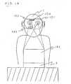
- FIG 1shows an example in which an operator 1 is sitting on a chair 8 to perform operation on a desk 7.
- the operator 1has a head-mounted image display device 2 (hereafter referred to as a "display device") mounted on his or her head.
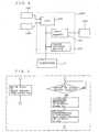
- a computer 3is disposed under the desk 7 to transmit image display information to the display device 2 via a connection cord (see Figure 2).
- the computer 3has connected thereto a foot switch 4 that acts as a trigger input means.
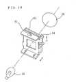
- the display device 2has a spectacles-like frame 101 in which a drive circuit 105 is housed, and one end of the connection cord 106 is connected to the drive circuit 105.
- the drive circuit 105 and the computer 3constitute an image generation means according to this invention.
- the frame 101also has mounted in front thereof a liquid crystal panel 102 comprising a lateral pair of liquid crystal display devices and a back light 104 that illuminates the liquid crystal panel 102 rearways, and an enlarging lens 103 is disposed on the inner surface of the frame 101 between the liquid crystal panel 102 and the operator's eyes 120.
- Image display information sent from the computer 3 via the connection cord 106is decoded by the drive circuit 105 and displayed on the liquid crystal panel 102.
- the liquid crystal panel 102is of a very small full color or monochrome type with a screen size of about 0.7 to 1.3 inch, and an image is enlarged by the enlarging lens 103 to about 14 inch at a visual range of 0.5 to 1.0 m and viewed by the operator 1 as a virtual image.
- the liquid crystal panel 102, the back light 104, and the enlarging lens 103are each provided for each of the operator's eyes 120, and ordinarily arranged so as to display the same screen to allow the eyes to see a single display screen.
- the display screenis located so as to be seen by the operator when he or she looks to a direction somewhat above the immediate front shown by arrow A in Figure 2 , and a lower part 122 has a high transmittance within the range of about 70 to about 95% so that when looking somewhat downward as shown by arrow B, the operator can look near his or her hands through the lower part 122 of the front surface of the frame 101.
- the upper part 123 of the front surface of the frame 101has a lower transmittance within the range of 0 to about 10% so as to prevent extraneous light from entering the frame.
- the frame 101has mounted thereon an angle sensor 1.07 that detects the direction and angle of the operator's head 1 when it moves vertically or horizontally and that transmits detected data to the computer 3 via the connection cord 106.
- An infrared ray LED 108is mounted over the enlarging lens 103, and a photosensor 109 is mounted under the lens 103 to detect the direction of the operator's line of sight and winking.
- the operator 1when looking somewhat upward, the operator 1 can view a display screen on the liquid crystal panel 102 as a virtual subscreen 5 on a virtual display screen 6 at a distance about 0.5 m to 1.0 m apart from the operator, and when looking somewhat downward, he or she can see an operation on the desk 7.
- Figure 3shows a scene as seen by the operator 1.
- both the entire virtual subscreen 5b and the lower part of a virtual subscreen 5c which are contained within the range shown by a display frame 51 corresponding to the maximum display range of the liquid crystal panel 102are shown somewhat above the field of view.
- the desk 7 at which the operator 1 is performing an operation and the operator's hands 131are shown somewhat below the field of view.
- the display device 2When the operator 1 turns his or her head to the right, the display device 2 also moves to the right, and the display frame 51 accordingly moves to the right.
- the angle sensor 107detects the direction and angle of the operator's head, and the virtual subscreen 5 from the computer 3 scrolls leftward according to the detected angle.
- the virtual subscreen within the display frame 51changes to the subscreen 5c, then changes to the subscreen 5d, ...., and so on. This is also true in the vertical direction.
- the output of the angle sensor 107 and the distance over which the virtual subscreen 5 scrollshave been adjusted in advance, a fixed relative locational relationship can be maintained between the desk 7 and the virtual subscreen 5.
- the operator 1can view part of a large number of virtual subscreens 5; it appears to the operator as if the subscreens were stuck to the virtual display screen 6 fixed to the space.
- the drive circuit 105 in the display device 2comprises a CPU 132, an image storage device 133, and an image memory 134, as shown in Figure 4.
- the image storage device 133has image data from the computer 3 stored therein, and the image memory 134 stores image data required to display a single screen (corresponding to the display frame 51) on the liquid crystal panel 102.
- the image storage device 133(and the CPU 132) may be built into the computer 3.
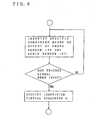
- the flowchart in Figure 5shows the operation of a control system in Figure 4.
- the image storage device 133regularly loads image data from the computer 3, and stores, for example, image data for the virtual subscreens 5a to 5e shown in Figure 3.
- the CPU 132checks whether or not the output of the angle sensor 107 has changed, and if it changes when the operator 1 moves his or her head, computes an address required to display a screen within the display frame 51 according to the change in angle to output it to the image storage device 133.
- the image storage device 133cuts image data corresponding to the address to output it to the image memory 134.
- the liquid crystal panel 102displays the image data. In this manner, the operator 1 can view a large number of virtual subscreens 5 simply by moving his or her head.
- the position of the display frame 51is determined by the output of the angle sensor 107 as described above. That is, this output determines the address in the image memory 134 which corresponds to the virtual display screen 6.
- the photosensor 109can detect what portion within the display frame 51 the operator is viewing.
- the photosensorenables the identification of the portion on the virtual display screen 6 which the operator is viewing, that is, the portion that corresponds to a particular address in the image memory 134.
- the movement of the operator's line of sightcorresponds to the movement of the mouse whereas the foot switch corresponds to the click button of the mouse).
- the operatorcan specify the portion within the virtual subscreen 5 which the operator 1 is viewing.
- the virtual subscreen 5 specified in the above mannermoves on the basis of the moving direction and distance determined from the most recent output of the photosensor 109 and the angle sensor 107. That is, the direction of the operator's line of sight is determined from the output of the photosensor 109 to determine where to move the virtual subscreen 5 within the display frame 51, and the direction of the operator's head is detected from the output of the angle sensor 107 to determine where to move the virtual subscreen 5 on the virtual screen 6.
- the virtual subscreen 5is thus moved, and the destination is updated until a trigger signal is input.
- the specified virtual subscreen 5stops moving and is then fixed to the operator's observation point. In this manner, an arbitrary virtual subscreen 5 can be moved freely to a desired position on the virtual screen 6.
- the combination of the number of times of stamps on the foot switch 4 and the interval between the stampscan be adjusted so as to send to the computer 3 an instruction for iconizing specified virtual subscreens 5 to reduce their sizes, thereby obtaining a clear display.
- the combination of the number of times of stamps on the foot switch 4 and the interval between the stampscan be adjusted so as to send to the computer 3 an instruction for enlarging specified virtual subscreens 5.
- this exampleenables a large number of materials to be referenced without putting the surroundings in disorder, thereby avoiding the decrease in working efficiency.
- operationcan be achieved simply by moving the operator's head, eyes, and foot, and his or her hands are not occupied in the operation, accidents such as falling of a part being experimented on or damage thereto can be avoided even during a complicated experiment.
- required materialscan be placed in positions in which they can be seen most clearly, the movement of eyes between a part being experimented on and the relevant material can be minimized to reduce the operator's fatigue.
- the results of measurementcan be displayed close to the operator as a virtual subscreen 5 to enable the experiment to be conducted more efficiently.
- FIG 8shows an example in which the operator 1 is repairing an apparatus 22.
- the display device 2is mounted on the operator's head, and an angle sensor 21 is mounted on the operator's chest, and a portable computer 13 and a push switch that acts as a trigger input means are mounted on the operator's waist.
- the display device 2is the same as in Example 1, and its description is thus omitted.
- the display device 2is connected to the computer 13 through a connection cord.
- the operator 1can view the display screen of a liquid crystal panel 102 as a virtual subscreen 5 on a virtual display screen 6, while in looking somewhat downward, the operator can view the apparatus 22 being repaired.
- Figure 9shows a scene as seen by the operator 1.
- both the entire virtual subscreen 5b and the lower part of a virtual subscreen 5c which are contained within the range shown by a display frame 51 corresponding to the maximum display range of the liquid crystal panel 102are shown somewhat above the field of view.
- the apparatus being repairedis shown somewhat below the field of view.
- the display device 2moves to the right, and the display frame 51 accordingly moves to the right.
- the virtual subscreen 5 from the computer 13then scrolls leftward according to the angle detected by an angle sensor 107 provided in the display device 2.
- the virtual subscreen within the display frame 51changes to the subscreen 5c, then changes to the subscreen 5d, ...., and so on. This is also true in the vertical direction.
- the angle sensor 21 mounted on the operator's chestdetects the operator's movement to inform the computer 13 of it.
- the computer 13arithmetically processes the output of the angle sensor 21 and the output of the angle sensor 107 provided in the display device 2, and if it determines that the output of the angle sensor 21 is equivalent to the output of the angle sensor 107, treats this as the movement of the entire body and allows the display on the virtual screen 6 to remain unchanged. That is, the relative locational relationship between the operator 1 and the virtual screen 6 is maintained constant, and the virtual screen 6 follows the movement of the operator's body. In this manner, the virtual screen 6 is always displayed around the operator 1, and the virtual subscreen 5 can be viewed as required simply by looking somewhat upward, whatever posture the operator is assuming.
- pressing the push switch 14 while viewing a virtual subscreen 5, as described in Embodiment 1,enables that subscreen 5 to be specified on the basis of the direction of the operator's line of sight detected by a photosensor 109 and the output of the angle sensor 107. Then, by moving the specified virtual subscreen 5 based on the output of both the photosensor 109 and the angle sensor 107 and subsequently pressing the push switch 14 again, the specified virtual subscreen 5 can be fixed to the current observation point. In this manner, an arbitrary virtual subscreen 5 can be moved to a desired position on the virtual screen 6.
- a desired instruction manualcan be viewed by moving the operator's head to display the corresponding virtual subscreen 5 within the display frame 51. Furthermore, by pressing the push switch 14 while viewing a desired virtual subscreen 5, moving the operator's head and line of sight to a position in which the subscreen can be seen clearly, and then pressing the push switch 14 again, the virtual subscreen can be fixed to the virtual screen 6. In addition, even if the operator moves to repair another part of the same apparatus, the virtual screen 6 remains in the same position around the operator 1, so required instruction manuals can be referenced whatever working posture the operator is assuming.
- the output of photosensor 109is obtained, for example, when the operator gives two consecutive quick winks. This enables both hands to be used for repairs even in Example 2. It is clear that voices or breathing can also be used as a trigger means.
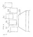
- the display device 2 in the example shown in Figure 10has a spectacles-like frame 101 including the liquid crystal panel 102, the enlarging lens 103, the back light 104, and a half mirror 135.
- the operator 1can view an enlarged display image on the liquid crystal panel 102 and an external image (the keyboard) through optical paths 136 and 138, respectively. These images can be synthesized by the half mirror 135 and viewed by the operator 1. The operator 1 thus feels as if the liquid crystal display image were present outside the frame (near the keyboard), resulting in improved workability.
- the operator 1can longitudinaly move relative to the operator 1, the position in which the virtual subscreen 5 for a liquid crystal display image is formed by moving the liquid crystal panel 102 in the direction 139 (along the optical path 136) in Figure 10. Then, matching this position with the screen 141 enables the above problems to be solved.
- the external image that overlaps the liquid crystal display imageis the monochrome screen, it does not substantially disturb the visibility of the display image. That is, the display image has a high visibility, leading to improved workability.
- the virtual subscreen 5 for a liquid crystal display imageis formed on the screen 141 close to the keyboard 140, so focusing for eyes need not be executed when the field of view is switched between the display image (the virtual subscreen 5) and the keyboard 140, resulting in a reduced fatigue of the operator.
- the above exampleenables the implementation of portable computers and word processors that have high portability and visibility and that do not affect the operator's health.
- the characteristics of the screenis not limited as long as they meet the objectives of this invention. For example, attaching a polarizing plate to the screen can reduce the brightness of the external image with the brightness of the liquid crystal display image maintained, thereby enabling high contrast display to be realized.
- the display device in Figures 13 and 14is of a single eye type.
- the cable for connecting the drive circuit to the main bodyis omitted for simplification.
- An image displayed on the liquid crystal panel 102is enlarged by the enlarging mirror 145, and the operator's right eye sees a large display image in front of the operator, while his or her left eye sees the exterior through the transparent spectacles-like frame 101.
- the problem in single eye-type display devices(the visibility of the display image is bad because the external image overlaps the display image, and the difference between focusing for the right and left eyes causes a significant fatigue of the operator) can be solved by adjusting the distance between the liquid crystal panel 102 and the enlarging mirror 145 so as to form on the screen a virtual subscreen 5 that is a display image so that the operator's left eye can see the screen 141.
- the virtual screen on the liquid, crystal display screenis formed on the monochrome and uniform screen 141, the visibility of the liquid crystal display screen is improved, and an equal focusing for the right and left eyes serves to reduce the operator's fatigue to almost the same level as in ordinary displays.
- the above examplecan provide portable computers and word processors that have a good portability and visibility and that do not affect the operator's health.
- a signal from the input device 150is input to the computer (an arithmetic unit) 3 via the connection cord 151, and image display information output from the computer 3 is transmitted to the head-mounted display device 2 via the connection cord 106.
- the head-mounted display device 2enables the simultaneous display of that input information such as the conditions of the input device 150 such as a keyboard or a data glove which is output by the computer 3 and the results of arithmetic operations from the computer 3, and indicates what keys can be currently used for input and what key the operator is touching.
- the display screen of the head-mounted display device 2is long, and is composed of an arithmetic operation result display screen 152 for displaying the results of arithmetic operations within the virtual subscreen 5 and a virtual keyboard display screen 153 for displaying the conditions of the input device.
- the input device 150By using as the input device 150, for example, a data glove having a means for measuring the transmittance of light through optical fibers to detect the bending of the operator's fingers and using a magnetic sensor to detect the relative position of the operator's hands, or a keyboard with a sensor having a position detection means such as a resistant film-like tablet, the input position can be detected, and the results of arithmetic operations can be viewed while a key assignment means 156 and an image synthesizing means 159 in the computer 3 are used to check on the virtual keyboard display screen 7 what key is being pressed.
- the input device 150detects positional information 154 for the positions of the operator's hands and fingers and on/off information 155 indicating whether or not any finger tip is pressing a key to transmit this information to the computer 3.
- the computer 3uses the key assignment means 156 to assign keys over the input range of the input device 150 for each application in advance in order to determine what keys correspond to input positional information 154, and determines from the on/off information 155 whether or not the key is activated in order to transmit the results to an arithmetic operation section 158 and an image synthesizing means 159 as input information 157.
- the arithmetic operation section 158performs arithmetic operations based on the input information 157 to transmit the results 160 to the image synthesizing means 159.
- the image synthesizing means 159continuously outputs the conditions of the input device 150 such that which key the operator's hand is touching based on the input information and the on/off state of the key, and outputs to the head-mounted display device 2 a signal as an image signal 161 which synthesizes the results of arithmetic operation 160 from the arithmetic operation section 158 into one image each time such an operation is carried out.
- the input device 150simply transmits the positional information 154 and the corresponding on/off information 155 to the computer 3, thereby enabling the key assignment means 156 to assign various keys without depending on the number of keys on the input device 150 and also allowing the virtual keyboard display section 153 to display various interfaces.
- the input device 150detects the input position and the corresponding on/off information (S10).
- the key assignment means 156determines to what key the input position corresponds, and transmits the contents of the corresponding key to the arithmetic operation section 158 (S11).
- the key assignment means 156determines whether or not the key is being pressed, and if so, informs the arithmetic operation section 158 of this state (S12).
- the image synthesizing means 159then generates an image on the virtual keyboard display screen 153 based on the input position and the on/off information (S13).
- the arithmetic operation section 158performs arithmetic operations based on transmitted information to generate an arithmetic operation result display screen 152 (S14).
- the image synthesizing means 159synthesizes as a single screen the virtual keyboard display screen 153 and the arithmetic operation result display screen 152 generated by the arithmetic operation section 11 to generate a virtual subscreen (S15).
- the input device 150includes resistant film-type devices, a collection of small switching elements, and various other devices. Next, the process executed by the assignment means 156 when a resistant film-type input device is used for key and pointing input is described in detail.
- the assignment means 156first determines the input method of the input device 150 (S20). If the input device 150 uses a key input method, the assignment means 156 divides the input plane into key areas (S21). The assignment means subsequently determines whether or not the input method has been switched (S22), and if not, receives the input signal (X, Y) (S23). It then examines to which key area the input signal (X, Y) corresponds (S24), and outputs the code for the corresponding key (S25).
- the assignment meansdetermines in S20 that the input device uses a pointing method, it then determines whether or not the input method has been switched (S26). If not, it receives the input signal and stores it in a buffer (X 0 , Y 0 ) (S27). It then receives the next input signal (X 1 , Y 1 ) to determine the difference between the this signal and the preceding signal (X 0 , Y 0 ) (S28). The assignment means determines whether or not the difference is, for example, 2 cm or longer (S29), and if so, treats this input as the result of clicking on (X 0 , Y 0 ) (S30). If the difference is shorter than 2 cm, the first signal is moved by the corresponding amount of movement. The above processing between step S26 and step S31 is performed in 0.01 second or shorter.
- one end of the connection cord 106is connected to the spectacle-like frame 101 for mounting the display device 2 on the operator's head in order to supply image signals and power to the drive circuit 105 and back light 104 disposed in the upper front of the spectacle-like frame 101.
- An image signal input to the drive circuit 105is decoded and displayed on the liquid crystal panel 102.
- the displayed image informationis illuminated by the back light 104 disposed on the rear face of the liquid crystal panel 102, and reaches the operator's eyes via a reflection mirror 170 and the enlarging lens 103 located on the front surface of the spectacle-like frame 101 and in front of the respective eyes of the operator.
- disposing a beam splitter between the liquid crystal panel 102 and the reflection mirror 135 to project an image in two different directionsenables the image to reach both eyes of the user via the reflection mirror and the enlarging lens located in front of the respective eyes.
- the liquid crystal panel 102is a long and small full color or monochrome LCD with a screen size of 1 to 2 inches, and allows a virtual subscreen 5 about 14 inches in size to be seen by the user via the enlarging lens 103 at a distance 500 to 1,000 mm apart from the user's eyes, as shown in Figure 20.
- the computermay be incorporated in the head-mounted display device, and in this case, signals from the input device are transmitted directly to the head-mounted display device and the computer.
- This computermay be implemented with an arithmetic operation device designed for a display device.
- the interface in the above example for which the key assignment means in the arithmetic operation device executes assignmentis not limited to a keyboard but may be a mouse, a joystick, or a pen.
- the input deviceis not limited to a tablet or a data glove as in the above embodiment, various input devices that can detect positional information and on/off information may be connected to the computer.
- the image synthesizing means in the computercan be omitted by separately driving and displaying the arithmetic operation result display screen and the virtual keyboard display screen to thereby implement the display section of the head-mounted display device.
- Figure 21is a perspective view wherein the display device 2 in the above embodiment is used as the display means.
- a signal of image display information output from the computer 3is transmitted to the display device 2 via the connection cable 106.
- the cable 106is connected to the computer 3 via a connector 23 so as to be removed easily therefrom.
- the display device 2 in Figure 21essentially has the same constitution as the device shown in Figure 20 except the liquid panel 102 can be removed easily from the frame 101.
- the reflection mirror 170can be moved vertically and longitudinally and also have its angle adjusted so that the operator can get a clear view.
- the frame 101serves to intercept extraneous light so that the image displayed on the liquid crystal panel 102 can be seen clearly.
- the exterior, however,must be seen through the frame 101, so the frame 101 preferably has a light transmittance of about 70 to 80%.
- power for driving the display device 2 and image information output from the main bodyare transmitted to the display device 2 via a connector recess 60 provided in the computer 3 main body, a connector convex 23 provided on the display device 2, and the connection cable 106 for connecting the computer 3 main body to the display device 2.
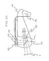
- Figure 22shows a screen used as the display device
- Figure 23shows a cross section of the screen.
- the liquid crystal panel 102removed from the display device 2, is plugged in a socket 24.
- An image displayed on the liquid crystal panel 102is illuminated by light from the back light 25, enlarged by a lens 206, and projected on a screen 27.
- the vertical position and size of the image 28can be adjusted by moving the liquid crystal panel 102 vertically or longitudinally in the socket 24.
- the screenis not necessarily a white panel, but may be a flat surface without patterns such as a wall.
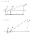
- Figures 24 and 25show the correlationship between the vertical position of the liquid crystal panel and the vertical position of the image 28. These figures show that moving the liquid crystal panel 102 vertically enables the vertical position of the image 28 to be adjusted.
- Figures 26 and 27show the correlationship between the longitudinal position of the liquid crystal panel and the size of the image 28. These figures show that moving the liquid crystal panel 102 longitudinally enables the size of the image 28 to be adjusted.
- S 1 and S 2the distance between the liquid crystal panel 102 and the enlarging lens 26 and the distance between the enlarging lens 26 and the screen 27
- expression (1)is given.
- (f)is a focal length.
- expression (2)is given.
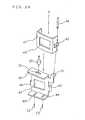
- Figure 28shows a perspective view of the structure of the socket 24, and Figure 29 shows an exploded perspective view of the socket 24.
- the liquid crystal panel 102has its vertical and longitudinal- directions adjusted by a pin 54 and an eccentric pin 55, respectively.
- the liquid crystal panel 102is inserted in the direction A in Figure 29.
- the socket 41fixes the liquid crystal panel 102.
- the pin 54is inserted into a tapped hole 51 via a hole 42 to fix the socket 41 to a socket 44.
- the rotational movement of the pin 54causes the socket 41 to move vertically and thus the liquid crystal panel 102 to move vertically.
- Pieces 46, 47 of the socket 44engage the socket 41, and the pieces and the socket 44 are fixed longitudinally together.
- Rotating the eccentric pin 55 in a long hole 50enables longitudinal movement.
- Pins 52, 53are inserted into long holes 48, 49 to prevent lateral deflection. Windows 43, 45 allow light from a light source to pass through.
- the liquid crystal panel in the display device 2 and the liquid crystal panel in the computer main bodycan not necessarily be removed from the respective devices, and the liquid crystal panels may be fixed and a display switch is provided to switch the display means for the computer.
- this inventionis not limited to the above - examples and is applicable to data processing apparatuses such as word processors.
- the single eye-type head-mounted display devicehas been described, but this invention is applicable to double eye-type head-mounted display devices.
- the above embodimentshave shown the use of a spectacle-type head-mounted image display device, this invention is applicable to other types of head-mounted image display devices such as goggle and helmet types.
- the data processing apparatus of the above configurationis used together with a head-mounted image display device as a display means, only the operator can directly view the contents of display, so the operator can process secret information without caring about people around the operator.
- the portability of this data processing apparatusis also good because the operator can use the apparatus in a natural position in a limited space as in an airplane or a train.
- the field of viewcan be moved easily between the virtual image viewed through the display device and the exterior including the keyboard, leading to the improved operability of the data processing apparatus.
- the liquid crystal Panel in the apparatus main bodymay be used to display image display information on the screen or the like. Such switching of the display means can be carried out easily.
- Figure 30shows a conventional computer in which its display section can be removed from its main body.
- a computer main body 3ais engaged with a display 63 via a connector recess 61 and a connector convex 62a.
- Figure 31shows an embodiment in which the display device 2 in the above embodiment is mounted on the computer 3 in Figure 30.
- the computer main body 3ais connected to the display device 2 via the connector recess 61, the connector convex 62, and the connector cable 106.
- both the connector convex 62a of the display 63 in Figure 30 and the connector convex 62 of the cable 106 in Figure 31conform to the same standard, both the conventional display 63 and the display device 2 according to this invention can be connected to the same main body. That is, a data processing apparatus is realized wherein the conventional display 63 and the display device 2 according to this example can be exchanged easily.
- this inventionis not limited to these embodiments, and is applicable to other data processing apparatuses such as word processors.
- the single eye-type head-mounted display devicehas been described, but this invention is applicable to double eye-type head-mounted display devices.
- this inventionis applicable to other types of head-mounted image display devices such as goggle and helmet types.
- this exampleis advantageous in that the display device can be removed easily from the data processing apparatus.
- the use of connectors conforming to a common specificationenables exchanges between a conventional display and the display device according to this embodiment.
- the back light in the display device of this exampleconsumes less power than displays used in conventional portable data processing apparatuses. As a result, the life of the battery can be extended, resulting in the significantly improved portability of the data processing apparatus according to this embodiment.
- output results from the computer 3are displayed on the display 63 and the display device 2 mounted on the operator's head.
- the user 1can execute processing while slightly moving his or her glance to view the image displayed on the display 63 and the virtual subscreen 5 created by the display device 2 mounted on his or her head.
- the virtual subscreen 5is generated by allowing an image displayed on the liquid crystal panel 102 to reach the user's eyes via an enlarging reflection mirror section 64.
- an output image from the arithmetic unit 70is assigned by an output information assignment means 72 to the respective image output devices for output, and then written to a graphic RAM 73 in an image output control section 71.
- the information written to the graphic RAM 73is managed on the basis of addresses, information output from the arithmetic unit 70 is output to the display device 2 and the display 63.
- the same informationmay be displayed on both the display device 2 and the display 63, or separate data sets may be displayed on the display device 2 and the display 63, respectively, and the information can also be transferred to an arbitrary image display device.
- the flowchart in Figure 34shows a process of outputting to a plurality of image display devices image information output from the arithmetic unit.
- image display devicesof apparently large capacities were connected to the arithmetic unit
- output information from the arithmetic unitis read into these display devices (S51). It is determined whether the read information comprises an image or controls display areas (S52). If the information is to control the display area, a memory address area that must be set in the graphic RAM 73 to display an image on each display device is determined on the basis of this information (S53). If the information comprises an image, parameters such as a display area (addresses) are determined on the basis of the memory address area (S54).
- step S55It is then determined whether or not the image information should be contained in the display area determined in step S54 (S55), that part of the information which is not associated with the display area is ignored during processing (S56) and the rest of the information which should be contained in the display area is address-converted (S57) and written to the graphic RAM (S58).
- Each of the image display devicedisplays the information in the assigned address area as required.
- the userviews the virtual subscreen 5 in part of his or her field of view and the other image display devices in the rest of his or her field of view, and can see the plurality of image display devices simply by slightly moving his or her line of sight.
- the numbers of arithmetic units and image display devicesare not limited, and in a system that processes a large amount of information using a plurality of arithmetic units, the results of processing can be displayed on the plurality of image display devices with only the information to be monitored displayed on a head-mounted display device.
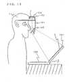
- a spectacles-like frame 101has mounted therein a liquid crystal panel display section 172 for the left eye and a liquid crystal panel display section 173 for the right eye.
- These liquid crystal panel display sections 172, 173form a virtual image on the retina of the eyes via a convex lens 103 and a mirror 170 in proportion to the strength of each image by irradiating the rear of the liquid crystal panel 102 from behind with extraneous light or light from the back light 104.
- a drive circuit for controlling these liquid crystal panels 102may be configured integrally with or separately from the spectacles-like frame so as to form images on the liquid crystal panel.
- a microphone 174is joined with the frame with a flexible joint 175 that is fixed to the position of the user's ears and which can be bent toward the user's mouth.
- a tracking sensor 176that acts as a position detection means is installed in the center of a frame 177 disposed so as to link the user's right and left ears together. The tracking sensor 176 detects the direction of the operator's line of sight using the moment of inertia effected when the user's head is turned.
- the display device in this embodimentincludes a mouse 180 and a keyboard 181.
- Figures 38 and 39show an embodiment in which a still picture obtained using the display device shown in Figure 35 is edited. These figures describe a display method in which a first and second display areas are displayed laterally on the display screen.
- the first display areausually contains still pictures that are shown in front of the operator.
- the second display areais displayed on the right of the screen according to the amount of the user's movement detected by the tracking sensor 176 when he or she turns to the right.
- the second display areadisplays attributes of the image data shown in the first display area.
- the tracking sensor 176detects this movement to create on the two liquid crystal panels 102 an image such as shown in Figure 39.
- This embodimentrelates to the synthesis of still pictures, in which the segments of the image (geometric models such as a tree, a house, or a car) are detected on the second display area and have their sizes adjusted.
- a "car”is input from the keyboard 181 to search its design file for an appropriate material. Searches are similarly carried out for the house and tree, and the size of the image is also adjusted on the second display area.
- the processed images materialsare transferred to the first display area in which they are synthesized against a background such as a mountain.
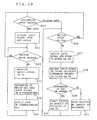
- the output of the tracking sensor 176is first input, and the direction of the operator's line of sight is detected on the basis of this input signal (S20). If the line of sight is determined to be to the left, background images are input to the first display area (S21) to select among them (S22). It is then determined on the basis of the output of the tracking sensor 176 whether or not the operator 1 has turned to the right (S23), and if not, the background image is then processed (S24). Until the processing is finished (S25), the process of selecting and processing a background images is repeated (S22 to S24).
- Audio inputdoes not simply consist of understanding words implied by commands but employs an audio input means called "WordSpotting” for unspecified speakers in which clauses can be input.
- sentencesare understood by neuro-computer processing in which nouns such as a tree, the right side, movement, the left, and a height are registered in advance to understand the entire sentence based on the occurrence probability of each word.
- a virtual imageis shown within the first display area via a wide angle lens, so the image is enlarged, and it is possible to allow the user to feel as if he or she were in that image.
- the distance over which the image movesis set on the computer to the size of the first display area, and the distance between the point of view and an object is calculated, in advance.
- a desired imagecan be input in the form of a voice to edit even minor positional relations while viewing the image in the first display area, without changing the point of view.
- the point of viewcan also be changed in the second display area as if this change were effected by camera work.
- Figure 42shows a simulation of motion picture data using the display device shown in Figure 35.
- a simulated image (a)is displayed in the first display area, while its attributes are displayed in the second display area.
- the second display areashows spatial area data that varies with the lapse of time, for example, temporally changing and graphed indications of the (b) locus of a flying airplane, (c) its speed, and the (d) hierarchical segmentation of the image segments.
- the locus of the airplanecan be obtained by plotting the temporally changing location of the airplane on the second display area.
- a speedcan be set for each plotted point based on the time vs. speed graph. If, for example, the speed is to be varied, the mouse is clicked on each step point to move it upward or downward.
- the segments that appear in the image data according to a certain time basecan be cut or pasted to the image based on the graph in which the image segments are hierarchically expressed.
- Such processing enabling the attributes of the image data to be temporally variedis very effective in editing segmented data during postproduction.
- the efficiency of editionis further improved by applying the depth of each image material and a parallax that corresponds to the difference between the right and left eyes in order to achieve three-dimensional display in which the operator feels as if he or she were viewing actual scenes as well as hierarchical display that expresses the depth well.
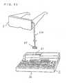
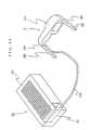
- an arithmetic unit 81is a portable type such as conventional notebook personal computers or personal computers.
- This arithmetic unit 81does not include a conventional open-type display but comprises an arithmetic unit main body 82 consisting of an arithmetic section, a memory section, and a keypad; and a cover 83 for protecting the upper surface of the keypad during storage or transportation.
- the cover 83is connected to the arithmetic unit main body 82 via a hinge-like connection 84 so as to be openably and closably retained.
- the inner surface of the cover 83has a buffering structure formed of an elastic body, and part of it forms a housing section 86 for housing the display device 2.
- the display device 2comprises a spectacles-like frame 101 in which the above optical system and drive circuit are housed, and is mounted on the user's head so as to cover his or her face.
- a bow 88is formed at both ends of the frame 101 so as to extend to the user's ears with hinges 89, and can be folded and housed.
- a communication cable 106 from the drive circuitprotrudes from one end of the bow 88 and connects to the arithmetic unit main body 82 through one end of the housing section 86.
- the drive circuit and the optical system in the display device 2enlarge an image information output from the arithmetic unit 81 and display it as a virtual image at a definite distance from the operator's face.
- the bow 88 on either side of the display device 2is folded and the display device is housed in the housing section 86.
- the communication cable 106is also folded and housed in the housing section 86, and the cover 83 is closed.
- This apparatusthen constitutes an integral structure like conventional portable data processing apparatuses. Consequently, it is possible to improve the portability and operability of the data processing apparatus while maintaining conventional advantages such as the ability to prepare confidential documents and to avoid locational limitations such as the need to fully open the display.
- the size and weight of the display device 2can be further reduced by dividing the drive circuit 105, which is housed in the display device 2 in this embodiment, into two parts, one of which is incorporated in the arithmetic unit 81 in such a way that this configuration will not result in the occurrence of noise.
- the data processing apparatus in Figure 45has the same basic configuration as in the preceding example.
- a housing section 90 for housing the display device 2is formed inside the arithmetic unit main body 82, and the connection cable 106 is connected to both the power supply in the arithmetic unit 81 and the arithmetic operation section.
- the volume of the arithmetic unit main body 82 main bodysomewhat increases, the need of a large cover is eliminated to reduce the size and weight of the apparatus and thereby improve portability, and the need of an open-type cover is eliminated to reduce the locational limitations, thereby further improving usability.
- the data processing apparatus in Figures 46 and 47also has the same basic configuration as in the two preceding embodiments. Like components carry like reference numerals, and their description is thus omitted.
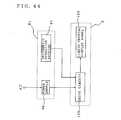
- the arithmetic unit 81has a charger therein, and the display device 2 has a chargeable battery therein.
- the arithmetic operation section 97 and the drive circuit 105communicate with each other by radio. The use, storage, or transportation of this apparatus thus requires a smaller space.
- the arithmetic unit 81has a charger 98 to which electric currents are supplied from a power supply 96 and a transmission circuit 99 to which signals are delivered from the arithmetic operation section 97.
- a signal supplied to the transmission circuit 99is modulated in the circuit 99, then transmitted and received via antennas 201, 202, and demodulated in a receive circuit 203.
- the signalis finally input to the drive circuit 105.
- the display device 2has a chargeable battery 204 therein for delivering drive currents to the drive circuit 105.
- An electrode contact 205 connected to the charger 98is exposed on the end face of the housing section 90. If, for example, the head-mounted image display device 2 is to be housed in the housing section 90 by inserting the antenna 202 side into the section 90, an electrode contact 206 is provided at the antenna 202-side end of the frame 101 that engages the electrode contact 205 when the display device is housed in the main body, and connected to the battery 204. In this configuration, when the head-mounted image display device 2 is housed in the main body, the electrode contact 205 of the charger 98 and the electrode contact 206 of the battery 204 are connected together. The battery 204 is thus charged while the display device 2 is housed in the main body, that is, while the device 2 is out of use.
- the arithmetic unit 81 and the display device 2are completely separated from each other, thereby substantially simplifying the use of the data processing apparatus 81 as well as the mounting and removal of the display device 2 from the housing section 90.
- the display device 2is housed in the same manner as in the embodiment in Figure 43, similar effects can be produced by adding the above components to the apparatus.
- the display device in each of the above embodimentsneed not necessarily be of a single eye type in which an optical system is disposed over only one eye while the other eye views an image, but may be of double eye type in which an optical system is disposed over each eye.
- the optical axis of each optical systemis preferably directed inward so that the glances of the two eyes intersect each other at an image visible distance (a distance at which a virtual image can be perceived), as in the natural way of looking at objects.
- the above componentsare not limited to the above contents, and various modifications may be made thereto without departing from the scope of this invention.
Landscapes
- Engineering & Computer Science (AREA)
- Theoretical Computer Science (AREA)
- Physics & Mathematics (AREA)
- Computer Hardware Design (AREA)
- General Engineering & Computer Science (AREA)
- General Physics & Mathematics (AREA)
- Human Computer Interaction (AREA)
- Optics & Photonics (AREA)
- Mathematical Physics (AREA)
- Multimedia (AREA)
- Signal Processing (AREA)
- Controls And Circuits For Display Device (AREA)
- Liquid Crystal Display Device Control (AREA)
- Control Of Indicators Other Than Cathode Ray Tubes (AREA)
- Devices For Indicating Variable Information By Combining Individual Elements (AREA)
- Instrument Panels (AREA)
- Liquid Crystal (AREA)
- Position Input By Displaying (AREA)
Description
- The present invention relates to a head-mounted image display device for displaying images on a screen showing a virtual space and to a data processing apparatus including this device.
- The design of electronic circuits or experiment thereon requires materials such as data sheets due to the need to confirm the specifications of parts to be used. In this case, the materials are scattered on and around the designer's desk, thereby limiting the working space or hindering the designer from finding required materials quickly. This reduces the working efficiency.
- To carry out design efficiently, computer aided engineering (CAE) for working out designs using computers has been introduced. That is, a paperless design environment has been established in which, for example, materials such as data sheets are registered in a computer to enable them to be displayed and referenced on the screen of the display as required. The above inconveniences have thus partly been eliminated.
- If, however, a large number of parts are to be used and a large number of materials must be referenced at the same time, although several windows can be opened on the screen to display different materials in the different windows, the windows must sometimes overlap each other if a large number of windows must be used simultaneously due to the physically limited size and resolution of the CRT display for displaying information. As a result, the amount of information that can be referenced at the same time is limited, and the efficiency provided by the introduction of CAE is thus limited; in some cases, it is faster to find required materials among those scattered on and around the table as described above.
- The working efficiency is also reduced in the maintenance or repair of an installed apparatus, wherein the operator must carry out such an operation while referencing instruction manuals and wherein because the surroundings are in disorder, the operator cannot place the manuals in positions in which they can be referenced appropriately. Under such conditions, however, it is further difficult to place a CRT display close to the operator, and the introduction of CAE is impossible. Thus, no other appropriate solutions were available.
- Several methods of mounting a display apparatus on the operator's head and displaying information from materials thereon have thus been proposed.
- Published Unexamined Patent Application No. 5-100192 describes a method of displaying screens from electronics such as word processors on a spectacle-like display, but this is only a spectacle-shaped variation of conventional displays and is not suited to the presentation of a large number of materials. Published Unexamined Patent Application No. 4-263283 proposes a portable virtual reality apparatus, but this simply provides an artificial reality apparatus and is not suited to the manipulation of displayed data.
- In addition, for conventional head-mounted image display devices, several problems arising from the need to alternatively view a virtual image on the liquid crystal display and the corresponding image on the external keyboard due to the large difference in image quality between these images, have been pointed out. To solve this problem, some conventional techniques cause a display image and the corresponding external image to overlap each other.
- Head-mounted image display devices of this type, however, also have problems. For example, in such apparatuses, the visibility is very bad because external images are simply caused to overlap the corresponding display images, and alternatively viewing different images may strain the operator's eyes.
- In addition, in head-mounted image display devices, when, for example, data is input to a word processor, keys to be pressed must be confirmed while viewing a display image, so the external keyboard must be checked while watching the display image.
- To solve this problem, a means for switching between an external image and the corresponding image from an arithmetic operational device may be provided, or a configuration that enables the use of part of the field of view for watching the display while using the other part for checking the exterior may be provided, as proposed in Published Unexamined Patent Application No. 5-100192.
- In this case, however, since data must be input while using a particular part of the field of view to check the input device, mounting the image display device on the operator's head eliminates the freedom of the operator's inputting position, and long time work thus results in a significant fatigue. In addition, if a keyboard is used as an input device, the input operation is very difficult when the keys are larger than the tips of the operator's fingers, so the limit of the practical size of portable terminals depends on the size of the keyboard. Furthermore, due to the fixed arrangement of keys in conventional keyboards, optimal key arrangements for various applications are not available.
- In this information-oriented society, more and more attention is being paid to multimedia applications, so people must often deal with data in which motion and still pictures are mixed. Under these circumstances, the need of complicated procedures for creating motion pictures hinders people without expertise from providing adequate expressions using multiple media effectively.
- For hypermedia applications, HyperCard commercially available from Apple Co., Ltd is popular, but requires a large number of mouse clicks, thereby possibly resulting in mistakes in clicking positions.
- For movie postproduction processes for processing, synthesizing, and editing movie materials, a large amount of time is required to complete the process due to the need to accurately carry out complex procedures according to pre-calculations, and the flexibility of these processes is limited; it is impossible to test various combinations of images during the process.
- In addition, if a head-mounted image display device is used, only the person wearing the device can view image display information output from a data processing apparatus. If a plurality of people have to view image display information output from the data processing apparatus, then:
- (1) these people must use a single head-mounted image display device in turn, or
- (2) another data processing apparatus with a CRT display must be provided.
- In this manner, a plurality of devices may be required according to a particular purpose and usage.
- Attempts are being made to reduce the size of computers and word processors, and the utilization of portable data processing apparatuses is increasing. Such portable data processing apparatuses ordinarily include an open type display that is opened in use. However, with the further reduction of the size of portable data processing apparatuses, the extension of the range within which such devices can be used, and the increase in demand for functions of publicly creating confidential documents, the use of head-mounted image display devices has been proposed. As in Published Unexamined Patent Application No. 5-100192, such apparatuses comprise an arithmetic processing device and a head-mounted image display device to display screen information output from the arithmetic operation device, through the head-mounted image display device as enlarged virtual images. In such conventional structures, the arithmetic operation device and the head-mounted image display device are always separated from each other, they must be carried separately, resulting in poor portability despite their reduced sizes. Even if the head-mounted image display device is carried in an outer sheath case, handling becomes cumbersome, and faults are likely to occur.
- The document "Eye Movements, for A Bidirectional Human Interface," R. Epworth, ICL Technical Journal November 1990, p. 384-411, discloses a head band mount display having input control via eye movements.
- It is an objective of this invention to provide a head-mounted image display device suitable to efficient design, experiment, maintenance, and repairs.
- It is another objective of this invention to provide a head-mounted image display device that has good portability and visibility and that does not affect the user's health.
- It is yet another objective of this invention to provide a head-mounted image display device that enables the operator to input data in a natural position without depending on the size of an input device.
- It is yet another objective of this invention to provide a head-mounted image display device that can be used for multimedia applications and that enables the user to check both an image display section and displayed information on the attributes of a displayed image simply by changing the direction of the field of view when editing still and motion pictures.
- It is still another objective of this invention to provide a head-mounted image display device that uses as an image retrieval method that is complicated when used with hypermedia applications a method for displaying retrieved attributes based on time series or hierarchies and that reduces mistakes attributable to the image retrieval method simply by switching the direction of the field of view between a first display area and a second display area.
- It is still another objective of this invention to provide a head-mounted image display device that enables the three-dimensional display of information displayed in the second display area the amount of which varies with changes in space or time by changing the parallax of the operator's eyes, thereby reducing mistakes in inputting hierarchical data.
- It is still another objective of this invention to provide a head-mounted image display device that can express even minor positional relationships in an image during edition in imaginative movie production methods in which voices are supplementarily input to process and edit movie materials and that in the edition of motion pictures, can express conditions based on time series such as partial acceleration and deceleration in such a way that they look like real conditions.
- It is still another objective of this invention to provide a data processing apparatus that can simply switch a display means between a head-mounted image display device and a screen or the like as required to display thereon image display information output from the data processing apparatus main body.
- It is still another objective of this invention to provide a data processing apparatus comprising a head-mounted image display device that is portable and easy to handle.
- A main embodiment of a head-mounted image display device according to this invention is defined in
claim 1. Claim 2 defines an additional embodiment.- With the above constitution, this invention enables the operator to precisely adjust the sizes of images and relative relationships among them during edition while viewing the images, by providing the location detection means for detecting the field of view in the horizontal or vertical directions and the voice input means joined with the frame using a flexible joint.
- Since the voice input means comprises a small microphone that enables unspecified speakers to input voices thereto, any user can wear this means. Furthermore, by inputting a form of voice input processing using WordSpotting on a neuro-computer, mistakes in input procedures are somewhat compensated for because associated keywords can be recognized on the basis of certain probabilistic determination, thereby enabling edition to be executed without the need to memorize all the commands.
- Since the location detection means can switch between the first and second display areas, the display area can be spatially classified into a plurality of pages, thereby enabling the overall picture to be confirmed during edition, in contrast to conventional techniques wherein an image and its attributes are displayed in a single page constituting a display area.
- Since the second display area for displaying attributes of an image displays space-time area data to be incorporated in the first display area, information that varies with the lapse of time can be processed appropriately.
- Since the second display area for displaying attributes of an image three-dimensionally displays hierarchical and space-time area data to be incorporated in the first display area with a parallax provided therein, the depth of images in the first display area and spatial-temporal area data can be edited and processed appropriately.
- Although the above display method has been described in conjunction with an embodiment that mainly displays images and in which an image is displayed to the right of its attributes, this invention is not limited to this arrangement and attribute data may be located to the left of the image or over or under the image.
- Figure 1 shows a head-mounted image display device according to an explanatory example;
- Figure 2 is a block diagram showing the details of the display device in Figure 1;
- Figure 3 shows a scene as seen by the operator in the example in Figure 1;
- Figure 4 is a block diagram showing the details of a control system in Figure 2;
- Figure 5 is a flowchart showing the operation of the control system in Figure 4;
- Figure 6 is a flowchart showing a method for specifying images in the example of Figure 1;
- Figure 7 is a flowchart showing a method for moving images in the example of Figure 1;
- Figure 8 shows a head-mounted image display device according to another example;
- Figure 9 shows a scene as seen by the operator in the example in Figure 8;
- Figure 10 shows a head-mounted image display device according to yet another example;
- Figure 11 describes a screen applied to the example in Figure 10;
- Figure 12 explains a usage of the example in figure 10;
- Figure 13 describes a usage of a head-mounted image display device according to still another example of this invention as seen laterally;
- Figure 14 explains the usage of the example in Figure 13 as seen frontways;
- Figure 15 describes the operator inputting data with a head-mounted image display device according to still another example of this invention (which displays input information and the results of arithmetic operations) mounted on the operator's head;
- Figure 16 explains the display screen of the image display device in Figure 15;
- Figure 17 is a block diagram showing the constitution of an arithmetic operation device in the example in Figure 15;
- Figure 18 is a flowchart showing the flow of signals in the example in Figure 15;
- Figure 19 is a flowchart showing a process executed in an assignment means in Figure 17;
- Figure 20 shows the configuration of the image display device in the example in Figure 15;
- Figure 21 is a perspective view showing a data processing apparatus, according to one example of this invention, which is used for a personal computer and a spectacle-like display used as a display means that is an example of the head-mounted image display device;
- Figure 22 is a side view showing the details of a head-mounted image display device for the data processing apparatus in Figure 21;
- Figure 23 is a perspective view showing a conventional data processing apparatus in which a main body and a display section can be separated from each other;
- Figures 24 and 25 show the relationship between the vertical movement of a liquid crystal display panel and the position of an image;
- Figures 26 and 27 show the relationship between the longitudinal movement of a liquid crystal display panel and the size of an image;
- Figure 28 is a perspective view showing a support mechanism for the liquid crystal display panel;
- Figure 29 is an exploded perspective view of Figure 28;
- Figure 30 is a perspective view showing a conventional data processing apparatus in which a main body and a display section can be separated from each other;
- Figure 31 is a perspective view showing a data processing apparatus to which an image display device according to still another embodiment of this invention can be connected;
- Figure 32 describes a data processing apparatus according to still another example of this invention;
- Figure 33 is a block diagram of a control system in the example in Figure 32;
- Figure 34 is a flowchart describing the control system in the example in Figure 32;
- Figure 35 shows a head-mounted image display device according to still another example of this invention;
- Figures 36 and 37 are a front and side views of an optical system respectively in the example in Figure 35;
- Figures 38 and 39 show a display method used when the head-mounted image display device is used to edit still pictures. Figure 38 is a model drawing showing the display method of this invention in which an image and its attributes are displayed in a first and second display areas that are located on the right and left of the screen, respectively;
- Figure 40 is a flowchart showing a process executed in the embodiment in Figure 38;
- Figure 41 is a flowchart describing a voice input procedure in the embodiment in Figure 38;
- Figure 42 is a model drawing showing an embodiment of the display method of this invention wherein the head-mounted image display device according to this invention is used to simulate motion pictures and wherein an image and its attributes are displayed in a first and second display areas that are located on the right and left of the screen, respectively. Figure 42(a) shows the results of a simulated image. Figure 42(b) shows the trace of the airplane. Figure 42(c) shows the speed of the airplane. Figure 42(d) shows the hierarchical segmentation of the image segments;
- Figure 43 is a model drawing showing a data processing apparatus according to still another example of this invention;
- Figure 44 is a block diagram showing a control system in the data processing apparatus in Figure 43;
- Figure 45 is a model drawing describing a data processing apparatus according to still another example of this invention;
- Figure 46 is a model drawing describing a data processing apparatus according to still another example of this invention; and
- Figure 47 is a block diagram showing a control system in the data processing apparatus in Figure 46.
- Figure 1 shows an example in which an
operator 1 is sitting on achair 8 to perform operation on adesk 7. Theoperator 1 has a head-mounted image display device 2 (hereafter referred to as a "display device") mounted on his or her head. Acomputer 3 is disposed under thedesk 7 to transmit image display information to thedisplay device 2 via a connection cord (see Figure 2). Furthermore, thecomputer 3 has connected thereto afoot switch 4 that acts as a trigger input means. - As shown in Figure 2, the
display device 2 has a spectacles-like frame 101 in which adrive circuit 105 is housed, and one end of theconnection cord 106 is connected to thedrive circuit 105. Thedrive circuit 105 and thecomputer 3 constitute an image generation means according to this invention. Theframe 101 also has mounted in front thereof aliquid crystal panel 102 comprising a lateral pair of liquid crystal display devices and aback light 104 that illuminates theliquid crystal panel 102 rearways, and an enlarginglens 103 is disposed on the inner surface of theframe 101 between theliquid crystal panel 102 and the operator'seyes 120. Image display information sent from thecomputer 3 via theconnection cord 106 is decoded by thedrive circuit 105 and displayed on theliquid crystal panel 102. - The
liquid crystal panel 102 is of a very small full color or monochrome type with a screen size of about 0.7 to 1.3 inch, and an image is enlarged by the enlarginglens 103 to about 14 inch at a visual range of 0.5 to 1.0 m and viewed by theoperator 1 as a virtual image. Theliquid crystal panel 102, theback light 104, and the enlarginglens 103 are each provided for each of the operator'seyes 120, and ordinarily arranged so as to display the same screen to allow the eyes to see a single display screen. - The display screen is located so as to be seen by the operator when he or she looks to a direction somewhat above the immediate front shown by arrow A in Figure 2 , and a
lower part 122 has a high transmittance within the range of about 70 to about 95% so that when looking somewhat downward as shown by arrow B, the operator can look near his or her hands through thelower part 122 of the front surface of theframe 101. Theupper part 123 of the front surface of theframe 101 has a lower transmittance within the range of 0 to about 10% so as to prevent extraneous light from entering the frame. - Furthermore, the
frame 101 has mounted thereon an angle sensor 1.07 that detects the direction and angle of the operator'shead 1 when it moves vertically or horizontally and that transmits detected data to thecomputer 3 via theconnection cord 106. Aninfrared ray LED 108 is mounted over the enlarginglens 103, and aphotosensor 109 is mounted under thelens 103 to detect the direction of the operator's line of sight and winking. - Referring Figure 1 again, when looking somewhat upward, the
operator 1 can view a display screen on theliquid crystal panel 102 as avirtual subscreen 5 on avirtual display screen 6 at a distance about 0.5 m to 1.0 m apart from the operator, and when looking somewhat downward, he or she can see an operation on thedesk 7. - Figure 3 shows a scene as seen by the
operator 1. In this figure, both the entirevirtual subscreen 5b and the lower part of a virtual subscreen 5c which are contained within the range shown by adisplay frame 51 corresponding to the maximum display range of theliquid crystal panel 102 are shown somewhat above the field of view. Thedesk 7 at which theoperator 1 is performing an operation and the operator'shands 131 are shown somewhat below the field of view. When theoperator 1 turns his or her head to the right, thedisplay device 2 also moves to the right, and thedisplay frame 51 accordingly moves to the right. Theangle sensor 107 detects the direction and angle of the operator's head, and thevirtual subscreen 5 from thecomputer 3 scrolls leftward according to the detected angle. The virtual subscreen within thedisplay frame 51 changes to the subscreen 5c, then changes to the subscreen 5d, ...., and so on. This is also true in the vertical direction. In this case, if the output of theangle sensor 107 and the distance over which thevirtual subscreen 5 scrolls have been adjusted in advance, a fixed relative locational relationship can be maintained between thedesk 7 and thevirtual subscreen 5. By moving his or her head, theoperator 1 can view part of a large number ofvirtual subscreens 5; it appears to the operator as if the subscreens were stuck to thevirtual display screen 6 fixed to the space. - The
drive circuit 105 in thedisplay device 2 comprises aCPU 132, animage storage device 133, and animage memory 134, as shown in Figure 4. Theimage storage device 133 has image data from thecomputer 3 stored therein, and theimage memory 134 stores image data required to display a single screen (corresponding to the display frame 51) on theliquid crystal panel 102. The image storage device 133 (and the CPU 132) may be built into thecomputer 3. - The flowchart in Figure 5 shows the operation of a control system in Figure 4. The
image storage device 133 regularly loads image data from thecomputer 3, and stores, for example, image data for the virtual subscreens 5a to 5e shown in Figure 3. TheCPU 132 checks whether or not the output of theangle sensor 107 has changed, and if it changes when theoperator 1 moves his or her head, computes an address required to display a screen within thedisplay frame 51 according to the change in angle to output it to theimage storage device 133. Theimage storage device 133 cuts image data corresponding to the address to output it to theimage memory 134. Theliquid crystal panel 102 displays the image data. In this manner, theoperator 1 can view a large number ofvirtual subscreens 5 simply by moving his or her head. - Next, a method for moving any one of the large number of
virtual subscreens 5 on thevirtual display screen 6 is described. - First, a method for specifying any one of the large number of
virtual subscreens 5 is described on the basis of the flowchart in Figure 6. - The position of the
display frame 51 is determined by the output of theangle sensor 107 as described above. That is, this output determines the address in theimage memory 134 which corresponds to thevirtual display screen 6. In addition, thephotosensor 109 can detect what portion within thedisplay frame 51 the operator is viewing. Thus, the photosensor enables the identification of the portion on thevirtual display screen 6 which the operator is viewing, that is, the portion that corresponds to a particular address in theimage memory 134. When the operator stamps on thefoot switch 4 that acts as a trigger input means, the identified address is confirmed to specify thevirtual subscreen 5 including the address, resulting the movement of the subscreen (this is like the movement of a window on the Windows screen using a mouse. The movement of the operator's line of sight corresponds to the movement of the mouse whereas the foot switch corresponds to the click button of the mouse). Thus, when stamping on thefoot switch 4 while viewing an arbitraryvirtual subscreen 5 to be moved, the operator can specify the portion within thevirtual subscreen 5 which theoperator 1 is viewing. - Next, a method for moving the specified
virtual subscreen 5 is described on the basis of the flowchart in Figure 7. - The
virtual subscreen 5 specified in the above manner moves on the basis of the moving direction and distance determined from the most recent output of thephotosensor 109 and theangle sensor 107. That is, the direction of the operator's line of sight is determined from the output of the photosensor 109 to determine where to move thevirtual subscreen 5 within thedisplay frame 51, and the direction of the operator's head is detected from the output of theangle sensor 107 to determine where to move thevirtual subscreen 5 on thevirtual screen 6. Thevirtual subscreen 5 is thus moved, and the destination is updated until a trigger signal is input. When the operator stamps on thefoot switch 4, the specifiedvirtual subscreen 5 stops moving and is then fixed to the operator's observation point. In this manner, an arbitraryvirtual subscreen 5 can be moved freely to a desired position on thevirtual screen 6. - It is then assumed that the
operator 1 is experimenting on an electronic circuit on thedesk 7. - Specifications and other materials for parts to be used in the experiment are registered in the
computer 3 in advance to display them as a plurality ofvirtual subscreens 5 on thevirtual screen 6. Theoperator 1 can view any material by displaying a desiredvirtual subscreen 5 within thedisplay frame 51. Furthermore, stamping on thefoot switch 4 while viewing a desiredvirtual subscreen 5 causes thatvirtual subscreen 5 to be specified, moving the operator's head enables it to be moved to a position in which it can be seen most clearly, and stamping on thefoot switch 4 again enables it to be fixed on thevirtual screen 6. - If the display is complicated due to a large number of
virtual subscreens 5 on thevirtual screen 6, after specifying thevirtual subscreen 5 as described in Figure 6, the combination of the number of times of stamps on thefoot switch 4 and the interval between the stamps can be adjusted so as to send to thecomputer 3 an instruction for iconizing specifiedvirtual subscreens 5 to reduce their sizes, thereby obtaining a clear display. - If displayed
virtual subscreens 5 are too small to see them clearly, the combination of the number of times of stamps on thefoot switch 4 and the interval between the stamps can be adjusted so as to send to thecomputer 3 an instruction for enlarging specifiedvirtual subscreens 5. - As described above, this example enables a large number of materials to be referenced without putting the surroundings in disorder, thereby avoiding the decrease in working efficiency. In addition, since operation can be achieved simply by moving the operator's head, eyes, and foot, and his or her hands are not occupied in the operation, accidents such as falling of a part being experimented on or damage thereto can be avoided even during a complicated experiment. Furthermore, since required materials can be placed in positions in which they can be seen most clearly, the movement of eyes between a part being experimented on and the relevant material can be minimized to reduce the operator's fatigue.
- Even if a large number of virtual subscreens are displayed, they can be distributed over the virtual screen and are enabled to scroll by movement of the operator's head, thereby preventing them from overlapping each other on the screen.
- Furthermore, by connecting instrument used for the experiment to the
computer 3 in advance, the results of measurement can be displayed close to the operator as avirtual subscreen 5 to enable the experiment to be conducted more efficiently. - Figure 8 shows an example in which the
operator 1 is repairing anapparatus 22. Thedisplay device 2 is mounted on the operator's head, and anangle sensor 21 is mounted on the operator's chest, and aportable computer 13 and a push switch that acts as a trigger input means are mounted on the operator's waist. Thedisplay device 2 is the same as in Example 1, and its description is thus omitted. Thedisplay device 2 is connected to thecomputer 13 through a connection cord. - In looking somewhat upward, the
operator 1 can view the display screen of aliquid crystal panel 102 as avirtual subscreen 5 on avirtual display screen 6, while in looking somewhat downward, the operator can view theapparatus 22 being repaired. - Figure 9 shows a scene as seen by the
operator 1. In this figure, both the entirevirtual subscreen 5b and the lower part of a virtual subscreen 5c which are contained within the range shown by adisplay frame 51 corresponding to the maximum display range of theliquid crystal panel 102 are shown somewhat above the field of view. The apparatus being repaired is shown somewhat below the field of view. When theoperator 1 turns his or her head to the right, thedisplay device 2 moves to the right, and thedisplay frame 51 accordingly moves to the right. Thevirtual subscreen 5 from thecomputer 13 then scrolls leftward according to the angle detected by anangle sensor 107 provided in thedisplay device 2. The virtual subscreen within thedisplay frame 51 changes to the subscreen 5c, then changes to the subscreen 5d, ...., and so on. This is also true in the vertical direction. In this case, if the output of theangle sensor 107 and the distance over which thevirtual subscreen 5 scrolls have been adjusted in advance, a fixed relative locational relationship can be maintained between the surrounding space and thevirtual subscreen 5. It appears to the operator as if the large number ofsubscreens 5 were stuck to thevirtual display screen 6 fixed to the space. - If the
operator 1 stoops or moves to repair another part of theapparatus 22, theangle sensor 21 mounted on the operator's chest detects the operator's movement to inform thecomputer 13 of it. Thecomputer 13 arithmetically processes the output of theangle sensor 21 and the output of theangle sensor 107 provided in thedisplay device 2, and if it determines that the output of theangle sensor 21 is equivalent to the output of theangle sensor 107, treats this as the movement of the entire body and allows the display on thevirtual screen 6 to remain unchanged. That is, the relative locational relationship between theoperator 1 and thevirtual screen 6 is maintained constant, and thevirtual screen 6 follows the movement of the operator's body. In this manner, thevirtual screen 6 is always displayed around theoperator 1, and thevirtual subscreen 5 can be viewed as required simply by looking somewhat upward, whatever posture the operator is assuming. - Furthermore, pressing the
push switch 14 while viewing avirtual subscreen 5, as described inEmbodiment 1, enables thatsubscreen 5 to be specified on the basis of the direction of the operator's line of sight detected by aphotosensor 109 and the output of theangle sensor 107. Then, by moving the specifiedvirtual subscreen 5 based on the output of both thephotosensor 109 and theangle sensor 107 and subsequently pressing thepush switch 14 again, the specifiedvirtual subscreen 5 can be fixed to the current observation point. In this manner, an arbitraryvirtual subscreen 5 can be moved to a desired position on thevirtual screen 6. - Next, it is assumed that the
operator 1 is actually repairing theapparatus 22. Instruction manuals and specifications required for repairs are registered in thecomputer 13 in advance. A plurality ofvirtual subscreens 5 are displayed on thevirtual screen 6, that is, stored in animage storage device 133. A desired instruction manual can be viewed by moving the operator's head to display the correspondingvirtual subscreen 5 within thedisplay frame 51. Furthermore, by pressing thepush switch 14 while viewing a desiredvirtual subscreen 5, moving the operator's head and line of sight to a position in which the subscreen can be seen clearly, and then pressing thepush switch 14 again, the virtual subscreen can be fixed to thevirtual screen 6. In addition, even if the operator moves to repair another part of the same apparatus, thevirtual screen 6 remains in the same position around theoperator 1, so required instruction manuals can be referenced whatever working posture the operator is assuming. - As an alternative to the trigger means described in Examples 1 and 2, the output of
photosensor 109 is obtained, for example, when the operator gives two consecutive quick winks. This enables both hands to be used for repairs even in Example 2. It is clear that voices or breathing can also be used as a trigger means. - The
display device 2 in the example shown in Figure 10 has a spectacles-like frame 101 including theliquid crystal panel 102, the enlarginglens 103, theback light 104, and ahalf mirror 135. Theoperator 1 can view an enlarged display image on theliquid crystal panel 102 and an external image (the keyboard) throughoptical paths 136 and 138, respectively. These images can be synthesized by thehalf mirror 135 and viewed by theoperator 1. Theoperator 1 thus feels as if the liquid crystal display image were present outside the frame (near the keyboard), resulting in improved workability. - With this configuration, however, a few problems may occur. First, the liquid crystal display image and the external image simply overlap each other, so the display image cannot be distinguished clearly. Second, since the distance between the operator and the virtual image cannot be matched easily with the distance between the operator and the keyboard, focusing for eyes must be carried out each time the field of view is switched between the liquid crystal display image and the keyboard contained in the synthesized image, resulting in a marked fatigue of the operator.
- These problems can be solved by employing part of an outer sheath case for the data processing apparatus and the keyboard as a screen. That is, the
rear face 141 of a cover for thekeyboard 140 of thecomputer 3 is used as a screen. This screen consists of an opaque material with a single color such as white, black, or blue, and is effective in improving the visibility of a liquid crystal display image that is allowed to overlap the screen image. The color and reflectivity of the screen are depends on the degree of this effect. - As in the example shown in Figure 1,2, the
operator 1 can longitudinaly move relative to theoperator 1, the position in which thevirtual subscreen 5 for a liquid crystal display image is formed by moving theliquid crystal panel 102 in the direction 139 (along the optical path 136) in Figure 10. Then, matching this position with thescreen 141 enables the above problems to be solved. - Since the external image that overlaps the liquid crystal display image is the monochrome screen, it does not substantially disturb the visibility of the display image. That is, the display image has a high visibility, leading to improved workability. In addition, the
virtual subscreen 5 for a liquid crystal display image is formed on thescreen 141 close to thekeyboard 140, so focusing for eyes need not be executed when the field of view is switched between the display image (the virtual subscreen 5) and thekeyboard 140, resulting in a reduced fatigue of the operator. - Consequently, the above example enables the implementation of portable computers and word processors that have high portability and visibility and that do not affect the operator's health.
- The characteristics of the screen is not limited as long as they meet the objectives of this invention. For example, attaching a polarizing plate to the screen can reduce the brightness of the external image with the brightness of the liquid crystal display image maintained, thereby enabling high contrast display to be realized.
- The display device in Figures 13 and 14 is of a single eye type. In these figures, the cable for connecting the drive circuit to the main body is omitted for simplification.
- An image displayed on the
liquid crystal panel 102 is enlarged by the enlargingmirror 145, and the operator's right eye sees a large display image in front of the operator, while his or her left eye sees the exterior through the transparent spectacles-likeframe 101. The problem in single eye-type display devices (the visibility of the display image is bad because the external image overlaps the display image, and the difference between focusing for the right and left eyes causes a significant fatigue of the operator) can be solved by adjusting the distance between theliquid crystal panel 102 and the enlargingmirror 145 so as to form on the screen avirtual subscreen 5 that is a display image so that the operator's left eye can see thescreen 141. That is, since the virtual screen on the liquid, crystal display screen is formed on the monochrome anduniform screen 141, the visibility of the liquid crystal display screen is improved, and an equal focusing for the right and left eyes serves to reduce the operator's fatigue to almost the same level as in ordinary displays. - Consequently, the above example can provide portable computers and word processors that have a good portability and visibility and that do not affect the operator's health.
- In the example in Figure 15, a signal from the
input device 150 is input to the computer (an arithmetic unit) 3 via theconnection cord 151, and image display information output from thecomputer 3 is transmitted to the head-mounteddisplay device 2 via theconnection cord 106. The head-mounteddisplay device 2 enables the simultaneous display of that input information such as the conditions of theinput device 150 such as a keyboard or a data glove which is output by thecomputer 3 and the results of arithmetic operations from thecomputer 3, and indicates what keys can be currently used for input and what key the operator is touching. - The display screen of the head-mounted
display device 2 is long, and is composed of an arithmetic operationresult display screen 152 for displaying the results of arithmetic operations within thevirtual subscreen 5 and a virtualkeyboard display screen 153 for displaying the conditions of the input device. By using as theinput device 150, for example, a data glove having a means for measuring the transmittance of light through optical fibers to detect the bending of the operator's fingers and using a magnetic sensor to detect the relative position of the operator's hands, or a keyboard with a sensor having a position detection means such as a resistant film-like tablet, the input position can be detected, and the results of arithmetic operations can be viewed while a key assignment means 156 and an image synthesizing means 159 in thecomputer 3 are used to check on the virtualkeyboard display screen 7 what key is being pressed. - Next, a method for outputting the results of arithmetic operations on the aritmetic operation
result display screen 152 and displaying the conditions of theinput device 150 on the virtualkeyboard display screen 153 is described with reference to the block diagram in Figure 17. Theinput device 150 detectspositional information 154 for the positions of the operator's hands and fingers and on/offinformation 155 indicating whether or not any finger tip is pressing a key to transmit this information to thecomputer 3. Thecomputer 3 uses the key assignment means 156 to assign keys over the input range of theinput device 150 for each application in advance in order to determine what keys correspond to inputpositional information 154, and determines from the on/offinformation 155 whether or not the key is activated in order to transmit the results to anarithmetic operation section 158 and an image synthesizing means 159 asinput information 157. Thearithmetic operation section 158 performs arithmetic operations based on theinput information 157 to transmit theresults 160 to the image synthesizing means 159. The image synthesizing means 159 continuously outputs the conditions of theinput device 150 such that which key the operator's hand is touching based on the input information and the on/off state of the key, and outputs to the head-mounted display device 2 a signal as animage signal 161 which synthesizes the results ofarithmetic operation 160 from thearithmetic operation section 158 into one image each time such an operation is carried out. Theinput device 150 simply transmits thepositional information 154 and the corresponding on/offinformation 155 to thecomputer 3, thereby enabling the key assignment means 156 to assign various keys without depending on the number of keys on theinput device 150 and also allowing the virtualkeyboard display section 153 to display various interfaces. - The flow of signals in the control system in Figure 17 is described with reference to Figure 18. The
input device 150 detects the input position and the corresponding on/off information (S10). The key assignment means 156 determines to what key the input position corresponds, and transmits the contents of the corresponding key to the arithmetic operation section 158 (S11). The key assignment means 156 then determines whether or not the key is being pressed, and if so, informs thearithmetic operation section 158 of this state (S12). The image synthesizing means 159 then generates an image on the virtualkeyboard display screen 153 based on the input position and the on/off information (S13). Thearithmetic operation section 158 performs arithmetic operations based on transmitted information to generate an arithmetic operation result display screen 152 (S14). The image synthesizing means 159 synthesizes as a single screen the virtualkeyboard display screen 153 and the arithmetic operationresult display screen 152 generated by the arithmetic operation section 11 to generate a virtual subscreen (S15). - The
input device 150 includes resistant film-type devices, a collection of small switching elements, and various other devices. Next, the process executed by the assignment means 156 when a resistant film-type input device is used for key and pointing input is described in detail. - The assignment means 156 first determines the input method of the input device 150 (S20). If the
input device 150 uses a key input method, the assignment means 156 divides the input plane into key areas (S21). The assignment means subsequently determines whether or not the input method has been switched (S22), and if not, receives the input signal (X, Y) (S23). It then examines to which key area the input signal (X, Y) corresponds (S24), and outputs the code for the corresponding key (S25). - If the assignment means determines in S20 that the input device uses a pointing method, it then determines whether or not the input method has been switched (S26). If not, it receives the input signal and stores it in a buffer (X0, Y0) (S27). It then receives the next input signal (X1, Y1) to determine the difference between the this signal and the preceding signal (X0, Y0) (S28). The assignment means determines whether or not the difference is, for example, 2 cm or longer (S29), and if so, treats this input as the result of clicking on (X0, Y0) (S30). If the difference is shorter than 2 cm, the first signal is moved by the corresponding amount of movement. The above processing between step S26 and step S31 is performed in 0.01 second or shorter.
- A shown in Figure 20, in the
display device 2 in Figure 15, one end of theconnection cord 106 is connected to the spectacle-like frame 101 for mounting thedisplay device 2 on the operator's head in order to supply image signals and power to thedrive circuit 105 and back light 104 disposed in the upper front of the spectacle-like frame 101. An image signal input to thedrive circuit 105 is decoded and displayed on theliquid crystal panel 102. The displayed image information is illuminated by theback light 104 disposed on the rear face of theliquid crystal panel 102, and reaches the operator's eyes via areflection mirror 170 and the enlarginglens 103 located on the front surface of the spectacle-like frame 101 and in front of the respective eyes of the operator. In another aspect, disposing a beam splitter between theliquid crystal panel 102 and thereflection mirror 135 to project an image in two different directions enables the image to reach both eyes of the user via the reflection mirror and the enlarging lens located in front of the respective eyes. - The
liquid crystal panel 102 is a long and small full color or monochrome LCD with a screen size of 1 to 2 inches, and allows avirtual subscreen 5 about 14 inches in size to be seen by the user via the enlarginglens 103 at a distance 500 to 1,000 mm apart from the user's eyes, as shown in Figure 20. - In the above example although the computer and the display device are separated from each other, the computer may be incorporated in the head-mounted display device, and in this case, signals from the input device are transmitted directly to the head-mounted display device and the computer. This computer may be implemented with an arithmetic operation device designed for a display device.
- The interface in the above example for which the key assignment means in the arithmetic operation device executes assignment is not limited to a keyboard but may be a mouse, a joystick, or a pen.
- Furthermore, the input device is not limited to a tablet or a data glove as in the above embodiment, various input devices that can detect positional information and on/off information may be connected to the computer.
- As an alternative to the example shown in Figure 16, the image synthesizing means in the computer (the arithmetic unit) can be omitted by separately driving and displaying the arithmetic operation result display screen and the virtual keyboard display screen to thereby implement the display section of the head-mounted display device.
- The example in Figures 21 to 29 shows the data processing apparatus according to this invention applied to a personal computer. Figure 21 is a perspective view wherein the
display device 2 in the above embodiment is used as the display means. A signal of image display information output from thecomputer 3 is transmitted to thedisplay device 2 via theconnection cable 106. To use the display means separately from the method described below, thecable 106 is connected to thecomputer 3 via aconnector 23 so as to be removed easily therefrom. - The
display device 2 in Figure 21 essentially has the same constitution as the device shown in Figure 20 except theliquid panel 102 can be removed easily from theframe 101. Thereflection mirror 170 can be moved vertically and longitudinally and also have its angle adjusted so that the operator can get a clear view. Theframe 101 serves to intercept extraneous light so that the image displayed on theliquid crystal panel 102 can be seen clearly. The exterior, however, must be seen through theframe 101, so theframe 101 preferably has a light transmittance of about 70 to 80%. - In addition, in the example in Figure 21, power for driving the
display device 2 and image information output from the main body are transmitted to thedisplay device 2 via aconnector recess 60 provided in thecomputer 3 main body, a connector convex 23 provided on thedisplay device 2, and theconnection cable 106 for connecting thecomputer 3 main body to thedisplay device 2. - Figure 22 shows a screen used as the display device, and Figure 23 shows a cross section of the screen.
- The
liquid crystal panel 102, removed from thedisplay device 2, is plugged in asocket 24. An image displayed on theliquid crystal panel 102 is illuminated by light from theback light 25, enlarged by alens 206, and projected on ascreen 27. As a result, the operator can view theimage 28. The vertical position and size of theimage 28 can be adjusted by moving theliquid crystal panel 102 vertically or longitudinally in thesocket 24. The screen is not necessarily a white panel, but may be a flat surface without patterns such as a wall. - Figures 24 and 25 show the correlationship between the vertical position of the liquid crystal panel and the vertical position of the
image 28. These figures show that moving theliquid crystal panel 102 vertically enables the vertical position of theimage 28 to be adjusted. - Figures 26 and 27 show the correlationship between the longitudinal position of the liquid crystal panel and the size of the
image 28. These figures show that moving theliquid crystal panel 102 longitudinally enables the size of theimage 28 to be adjusted. When the distance between theliquid crystal panel 102 and the enlarginglens 26 and the distance between the enlarginglens 26 and thescreen 27 are referred to as S1 and S2, respectively, expression (1) is given. (f) is a focal length. In addition, when the size of the image is referred to as β, expression (2) is given.

- In expression (1), S2 increases with decreasing S1, while S2 decreases with increasing S1. Consequently, the size of the image β increase with decreasing S1 while it decreases with increasing S1.
- Figure 28 shows a perspective view of the structure of the
socket 24, and Figure 29 shows an exploded perspective view of thesocket 24. - The
liquid crystal panel 102 has its vertical and longitudinal- directions adjusted by apin 54 and aneccentric pin 55, respectively. Theliquid crystal panel 102 is inserted in the direction A in Figure 29. Thesocket 41 fixes theliquid crystal panel 102. Thepin 54 is inserted into a tappedhole 51 via ahole 42 to fix thesocket 41 to asocket 44. Thus, the rotational movement of thepin 54 causes thesocket 41 to move vertically and thus theliquid crystal panel 102 to move vertically.Pieces socket 44 engage thesocket 41, and the pieces and thesocket 44 are fixed longitudinally together. Rotating theeccentric pin 55 in along hole 50 enables longitudinal movement.Pins long holes Windows - Although the above examples have shown an example of a liquid crystal panel of a detachable structure, the liquid crystal panel in the
display device 2 and the liquid crystal panel in the computer main body can not necessarily be removed from the respective devices, and the liquid crystal panels may be fixed and a display switch is provided to switch the display means for the computer. - In addition, although the above example has referred to the use of a personal computer, this invention is not limited to the above - examples and is applicable to data processing apparatuses such as word processors. The single eye-type head-mounted display device has been described, but this invention is applicable to double eye-type head-mounted display devices. Furthermore, although the above embodiments have shown the use of a spectacle-type head-mounted image display device, this invention is applicable to other types of head-mounted image display devices such as goggle and helmet types.
- If the data processing apparatus of the above configuration is used together with a head-mounted image display device as a display means, only the operator can directly view the contents of display, so the operator can process secret information without caring about people around the operator. The portability of this data processing apparatus is also good because the operator can use the apparatus in a natural position in a limited space as in an airplane or a train. In addition, the field of view can be moved easily between the virtual image viewed through the display device and the exterior including the keyboard, leading to the improved operability of the data processing apparatus.
- If a plurality of people desire to simultaneously see image display information output from the data processing apparatus, the liquid crystal Panel in the apparatus main body may be used to display image display information on the screen or the like. Such switching of the display means can be carried out easily.
- Figure 30 shows a conventional computer in which its display section can be removed from its main body. A computer main body 3a is engaged with a
display 63 via aconnector recess 61 and a connector convex 62a. - Figure 31 shows an embodiment in which the
display device 2 in the above embodiment is mounted on thecomputer 3 in Figure 30. In this embodiment, the computer main body 3a is connected to thedisplay device 2 via theconnector recess 61, the connector convex 62, and theconnector cable 106. - If both the connector convex 62a of the
display 63 in Figure 30 and the connector convex 62 of thecable 106 in Figure 31 conform to the same standard, both theconventional display 63 and thedisplay device 2 according to this invention can be connected to the same main body. That is, a data processing apparatus is realized wherein theconventional display 63 and thedisplay device 2 according to this example can be exchanged easily. - Although the above examples use a computer as the data processing apparatus, this invention is not limited to these embodiments, and is applicable to other data processing apparatuses such as word processors. The single eye-type head-mounted display device has been described, but this invention is applicable to double eye-type head-mounted display devices. Furthermore, although the above examples have shown the use of a spectacles-type head-mounted image display device, this invention is applicable to other types of head-mounted image display devices such as goggle and helmet types.
- As is apparent from the above explanation, this example is advantageous in that the display device can be removed easily from the data processing apparatus. In addition, the use of connectors conforming to a common specification enables exchanges between a conventional display and the display device according to this embodiment. Furthermore, the back light in the display device of this example consumes less power than displays used in conventional portable data processing apparatuses. As a result, the life of the battery can be extended, resulting in the significantly improved portability of the data processing apparatus according to this embodiment.
- In the image display system in Figure 32, output results from the
computer 3 are displayed on thedisplay 63 and thedisplay device 2 mounted on the operator's head. Theuser 1 can execute processing while slightly moving his or her glance to view the image displayed on thedisplay 63 and thevirtual subscreen 5 created by thedisplay device 2 mounted on his or her head. Thevirtual subscreen 5 is generated by allowing an image displayed on theliquid crystal panel 102 to reach the user's eyes via an enlargingreflection mirror section 64. - In the control system of the display device in Figure 33, an output image from the
arithmetic unit 70 is assigned by an output information assignment means 72 to the respective image output devices for output, and then written to agraphic RAM 73 in an imageoutput control section 71. The information written to thegraphic RAM 73 is managed on the basis of addresses, information output from thearithmetic unit 70 is output to thedisplay device 2 and thedisplay 63. For example, the same information may be displayed on both thedisplay device 2 and thedisplay 63, or separate data sets may be displayed on thedisplay device 2 and thedisplay 63, respectively, and the information can also be transferred to an arbitrary image display device. - The flowchart in Figure 34 shows a process of outputting to a plurality of image display devices image information output from the arithmetic unit. As if Image display devices of apparently large capacities were connected to the arithmetic unit, output information from the arithmetic unit is read into these display devices (S51). It is determined whether the read information comprises an image or controls display areas (S52). If the information is to control the display area, a memory address area that must be set in the
graphic RAM 73 to display an image on each display device is determined on the basis of this information (S53). If the information comprises an image, parameters such as a display area (addresses) are determined on the basis of the memory address area (S54). It is then determined whether or not the image information should be contained in the display area determined in step S54 (S55), that part of the information which is not associated with the display area is ignored during processing (S56) and the rest of the information which should be contained in the display area is address-converted (S57) and written to the graphic RAM (S58). Each of the image display device displays the information in the assigned address area as required. - The user views the
virtual subscreen 5 in part of his or her field of view and the other image display devices in the rest of his or her field of view, and can see the plurality of image display devices simply by slightly moving his or her line of sight. - Although, in the above example, two image display devices are connected to the portable computer, the numbers of arithmetic units and image display devices are not limited, and in a system that processes a large amount of information using a plurality of arithmetic units, the results of processing can be displayed on the plurality of image display devices with only the information to be monitored displayed on a head-mounted display device.
- In the display device in Figure 35, a spectacles-
like frame 101 has mounted therein a liquid crystalpanel display section 172 for the left eye and a liquid crystalpanel display section 173 for the right eye. These liquid crystalpanel display sections convex lens 103 and amirror 170 in proportion to the strength of each image by irradiating the rear of theliquid crystal panel 102 from behind with extraneous light or light from theback light 104. A drive circuit for controlling theseliquid crystal panels 102 may be configured integrally with or separately from the spectacles-like frame so as to form images on the liquid crystal panel. - A
microphone 174 is joined with the frame with a flexible joint 175 that is fixed to the position of the user's ears and which can be bent toward the user's mouth. A trackingsensor 176 that acts as a position detection means is installed in the center of aframe 177 disposed so as to link the user's right and left ears together. The trackingsensor 176 detects the direction of the operator's line of sight using the moment of inertia effected when the user's head is turned. The display device in this embodiment includes a mouse 180 and akeyboard 181. - Figures 38 and 39 show an embodiment in which a still picture obtained using the display device shown in Figure 35 is edited. These figures describe a display method in which a first and second display areas are displayed laterally on the display screen.
- The first display area usually contains still pictures that are shown in front of the operator. The second display area is displayed on the right of the screen according to the amount of the user's movement detected by the tracking
sensor 176 when he or she turns to the right. The second display area displays attributes of the image data shown in the first display area. In this case, when the user turns to the right, the trackingsensor 176 detects this movement to create on the twoliquid crystal panels 102 an image such as shown in Figure 39. This embodiment relates to the synthesis of still pictures, in which the segments of the image (geometric models such as a tree, a house, or a car) are detected on the second display area and have their sizes adjusted. In this case, for example, a "car" is input from thekeyboard 181 to search its design file for an appropriate material. Searches are similarly carried out for the house and tree, and the size of the image is also adjusted on the second display area. The processed images materials are transferred to the first display area in which they are synthesized against a background such as a mountain. - Next, the above editing process is described with reference to the flowchart in Figure 40. The output of the
tracking sensor 176 is first input, and the direction of the operator's line of sight is detected on the basis of this input signal (S20). If the line of sight is determined to be to the left, background images are input to the first display area (S21) to select among them (S22). It is then determined on the basis of the output of thetracking sensor 176 whether or not theoperator 1 has turned to the right (S23), and if not, the background image is then processed (S24). Until the processing is finished (S25), the process of selecting and processing a background images is repeated (S22 to S24). - When the processing has been finished (S25), it is then determined whether or not to add data to the image (S26). If it is determined that data should be added, attributes data is added to the first display area (S27).
- Voice input is then used to edit the details of the layout (S28). This process is described later. When the edition is finished (S29), the series of processing is completed.
- On the other hand, if the direction of the operator's line of sight is determined to be to the right when the direction of the line of sight is detected (S20), attributes data is input to the second display area (S30). A reference coordinate position is determined (S31), and attributes data is searched for (S32). When the search is finished (S33), the attributes data is processed (S34). When the processing is finished, it is determined whether or not edition will be subsequently carried out (S36). If so, segments to be edited are selected (S37). It is then determined whether or not the
operator 1 is looking to the left, and if so, the reference coordinates are calculated (S39) and the process transfers to the above step S27. Otherwise, that is, if the operator is determined to be still looking to the right, the process returns to step S34 to repeat the process of processing attributes data and selecting segments to be edited. - An audio editing process is described with reference to the flowchart in Figure 41. Audio input does not simply consist of understanding words implied by commands but employs an audio input means called "WordSpotting" for unspecified speakers in which clauses can be input.
- In this audio input means, sentences are understood by neuro-computer processing in which nouns such as a tree, the right side, movement, the left, and a height are registered in advance to understand the entire sentence based on the occurrence probability of each word.
- In this case, a virtual image is shown within the first display area via a wide angle lens, so the image is enlarged, and it is possible to allow the user to feel as if he or she were in that image. The distance over which the image moves is set on the computer to the size of the first display area, and the distance between the point of view and an object is calculated, in advance. During edition, a desired image can be input in the form of a voice to edit even minor positional relations while viewing the image in the first display area, without changing the point of view.
- The point of view can also be changed in the second display area as if this change were effected by camera work.
- Figure 42 shows a simulation of motion picture data using the display device shown in Figure 35. A simulated image (a) is displayed in the first display area, while its attributes are displayed in the second display area. The second display area shows spatial area data that varies with the lapse of time, for example, temporally changing and graphed indications of the (b) locus of a flying airplane, (c) its speed, and the (d) hierarchical segmentation of the image segments.
- In this embodiment, the locus of the airplane can be obtained by plotting the temporally changing location of the airplane on the second display area. A speed can be set for each plotted point based on the time vs. speed graph. If, for example, the speed is to be varied, the mouse is clicked on each step point to move it upward or downward. The segments that appear in the image data according to a certain time base can be cut or pasted to the image based on the graph in which the image segments are hierarchically expressed.
- Such processing enabling the attributes of the image data to be temporally varied is very effective in editing segmented data during postproduction. The efficiency of edition is further improved by applying the depth of each image material and a parallax that corresponds to the difference between the right and left eyes in order to achieve three-dimensional display in which the operator feels as if he or she were viewing actual scenes as well as hierarchical display that expresses the depth well.
- In the data processing apparatus in Figure 43, an
arithmetic unit 81 is a portable type such as conventional notebook personal computers or personal computers. Thisarithmetic unit 81, however, does not include a conventional open-type display but comprises an arithmetic unitmain body 82 consisting of an arithmetic section, a memory section, and a keypad; and acover 83 for protecting the upper surface of the keypad during storage or transportation. As in conventional data processing apparatuses, thecover 83 is connected to the arithmetic unitmain body 82 via a hinge-like connection 84 so as to be openably and closably retained. The inner surface of thecover 83 has a buffering structure formed of an elastic body, and part of it forms ahousing section 86 for housing thedisplay device 2. Thedisplay device 2 comprises a spectacles-like frame 101 in which the above optical system and drive circuit are housed, and is mounted on the user's head so as to cover his or her face. Abow 88 is formed at both ends of theframe 101 so as to extend to the user's ears withhinges 89, and can be folded and housed. Acommunication cable 106 from the drive circuit protrudes from one end of thebow 88 and connects to the arithmetic unitmain body 82 through one end of thehousing section 86. - In operation, when the head-mounted
image display device 2 is fixed to the user's head via theframe 101, and thearithmetic unit 81 is driven, then the drive circuit and the optical system in thedisplay device 2 enlarge an image information output from thearithmetic unit 81 and display it as a virtual image at a definite distance from the operator's face. In storage or transportation, thebow 88 on either side of thedisplay device 2 is folded and the display device is housed in thehousing section 86. Thecommunication cable 106 is also folded and housed in thehousing section 86, and thecover 83 is closed. This apparatus then constitutes an integral structure like conventional portable data processing apparatuses. Consequently, it is possible to improve the portability and operability of the data processing apparatus while maintaining conventional advantages such as the ability to prepare confidential documents and to avoid locational limitations such as the need to fully open the display. - The operation of the above example is explained with reference to the block diagram in Figure 44. An electric current supplied from an external power supply AC input is allowed to branch into two flows at a
power circuit 96 in thearithmetic unit 81, one of which is fed to thearithmetic operation section 97. The other flow and the output of thearithmetic operation section 97 are supplied to thedrive circuit 105 in thedisplay device 2 via theconnection cable 106, and then converted into a liquid crystal driving signal to drive theliquid crystal panel 102. In this block diagram, components that are not required for the explanation are omitted and are not described. In addition, the size and weight of thedisplay device 2 can be further reduced by dividing thedrive circuit 105, which is housed in thedisplay device 2 in this embodiment, into two parts, one of which is incorporated in thearithmetic unit 81 in such a way that this configuration will not result in the occurrence of noise. - The data processing apparatus in Figure 45 has the same basic configuration as in the preceding example. In this embodiment, a
housing section 90 for housing thedisplay device 2 is formed inside the arithmetic unitmain body 82, and theconnection cable 106 is connected to both the power supply in thearithmetic unit 81 and the arithmetic operation section. In this constitution, although the volume of the arithmetic unitmain body 82 main body somewhat increases, the need of a large cover is eliminated to reduce the size and weight of the apparatus and thereby improve portability, and the need of an open-type cover is eliminated to reduce the locational limitations, thereby further improving usability. - The data processing apparatus in Figures 46 and 47 also has the same basic configuration as in the two preceding embodiments. Like components carry like reference numerals, and their description is thus omitted.
- In this embodiment, the
arithmetic unit 81 has a charger therein, and thedisplay device 2 has a chargeable battery therein. In addition, thearithmetic operation section 97 and thedrive circuit 105 communicate with each other by radio. The use, storage, or transportation of this apparatus thus requires a smaller space. Thearithmetic unit 81 has acharger 98 to which electric currents are supplied from apower supply 96 and a transmission circuit 99 to which signals are delivered from thearithmetic operation section 97. A signal supplied to the transmission circuit 99 is modulated in the circuit 99, then transmitted and received viaantennas circuit 203. The signal is finally input to thedrive circuit 105. Thedisplay device 2 has achargeable battery 204 therein for delivering drive currents to thedrive circuit 105. - An
electrode contact 205 connected to thecharger 98 is exposed on the end face of thehousing section 90. If, for example, the head-mountedimage display device 2 is to be housed in thehousing section 90 by inserting theantenna 202 side into thesection 90, anelectrode contact 206 is provided at the antenna 202-side end of theframe 101 that engages theelectrode contact 205 when the display device is housed in the main body, and connected to thebattery 204. In this configuration, when the head-mountedimage display device 2 is housed in the main body, theelectrode contact 205 of thecharger 98 and theelectrode contact 206 of thebattery 204 are connected together. Thebattery 204 is thus charged while thedisplay device 2 is housed in the main body, that is, while thedevice 2 is out of use. - In this constitution, the
arithmetic unit 81 and thedisplay device 2 are completely separated from each other, thereby substantially simplifying the use of thedata processing apparatus 81 as well as the mounting and removal of thedisplay device 2 from thehousing section 90. In addition, even when thedisplay device 2 is housed in the same manner as in the embodiment in Figure 43, similar effects can be produced by adding the above components to the apparatus. - The display device in each of the above embodiments need not necessarily be of a single eye type in which an optical system is disposed over only one eye while the other eye views an image, but may be of double eye type in which an optical system is disposed over each eye. In this case, the optical axis of each optical system is preferably directed inward so that the glances of the two eyes intersect each other at an image visible distance (a distance at which a virtual image can be perceived), as in the natural way of looking at objects. In addition, the above components are not limited to the above contents, and various modifications may be made thereto without departing from the scope of this invention.


Claims (2)
- A head-mounted image display device (2) comprising a liquid crystal display panel (102) and an enlarging optical system (103), which are housed in a frame (101) and wherein images generated on said liquid crystal display panel (102) through said enlarging optical system (103) are visible in the field of view of a user (1) in front of said frame (101); having:a location detection means (107), (109) and (108) for detecting the field of view of said user (1) in the horizontal or vertical directions;characterized in that it further comprises :an image generation means for segmenting the display area into a first display area for displaying images and a second display area for displaying attributes of an image, and switching between said first and second display areas based on the output of said location detection means.
- An image display device according to Claim 1 wherein said image generation means is arranged to switch between said first and second display areas based on the output of said location detection means (107), (109) and (108), and controls attribute data shown in said second display area according to voice input signals.
Applications Claiming Priority (17)
| Application Number | Priority Date | Filing Date | Title |
|---|---|---|---|
| JP20086393 | 1993-08-12 | ||
| JP20086393 | 1993-08-12 | ||
| JP28845993 | 1993-11-17 | ||
| JP28845993 | 1993-11-17 | ||
| JP29095593 | 1993-11-19 | ||
| JP29095293 | 1993-11-19 | ||
| JP29095593 | 1993-11-19 | ||
| JP29095293 | 1993-11-19 | ||
| JP29095393 | 1993-11-19 | ||
| JP29095393 | 1993-11-19 | ||
| JP29847893 | 1993-11-29 | ||
| JP29847893 | 1993-11-29 | ||
| JP32858693 | 1993-12-24 | ||
| JP32859493 | 1993-12-24 | ||
| JP32858693 | 1993-12-24 | ||
| JP32859493 | 1993-12-24 | ||
| EP94922367AEP0714043B1 (en) | 1993-08-12 | 1994-08-12 | Head mount type image display device and information processor equipped with the device |
Related Parent Applications (1)
| Application Number | Title | Priority Date | Filing Date |
|---|---|---|---|
| EP94922367ADivisionEP0714043B1 (en) | 1993-08-12 | 1994-08-12 | Head mount type image display device and information processor equipped with the device |
Publications (3)
| Publication Number | Publication Date |
|---|---|
| EP1326121A2 EP1326121A2 (en) | 2003-07-09 |
| EP1326121A3 EP1326121A3 (en) | 2003-07-16 |
| EP1326121B1true EP1326121B1 (en) | 2006-09-13 |
Family
ID=27573423
Family Applications (4)
| Application Number | Title | Priority Date | Filing Date |
|---|---|---|---|
| EP94922367AExpired - LifetimeEP0714043B1 (en) | 1993-08-12 | 1994-08-12 | Head mount type image display device and information processor equipped with the device |
| EP03007862AExpired - LifetimeEP1326120B1 (en) | 1993-08-12 | 1994-08-12 | Head-mounted image display device and data processing apparatus including the same |
| EP03007864AExpired - LifetimeEP1326122B1 (en) | 1993-08-12 | 1994-08-12 | Head-mounted image display device and data processing apparatus including the same |
| EP03007863AExpired - LifetimeEP1326121B1 (en) | 1993-08-12 | 1994-08-12 | Head-mounted image display device and data processing apparatus including the same |
Family Applications Before (3)
| Application Number | Title | Priority Date | Filing Date |
|---|---|---|---|
| EP94922367AExpired - LifetimeEP0714043B1 (en) | 1993-08-12 | 1994-08-12 | Head mount type image display device and information processor equipped with the device |
| EP03007862AExpired - LifetimeEP1326120B1 (en) | 1993-08-12 | 1994-08-12 | Head-mounted image display device and data processing apparatus including the same |
| EP03007864AExpired - LifetimeEP1326122B1 (en) | 1993-08-12 | 1994-08-12 | Head-mounted image display device and data processing apparatus including the same |
Country Status (5)
| Country | Link |
|---|---|
| US (3) | US5977935A (en) |
| EP (4) | EP0714043B1 (en) |
| JP (1) | JP3872100B2 (en) |
| DE (4) | DE69434843T2 (en) |
| WO (1) | WO1995005620A1 (en) |
Cited By (19)
| Publication number | Priority date | Publication date | Assignee | Title |
|---|---|---|---|---|
| US10558050B2 (en) | 2014-01-24 | 2020-02-11 | Mentor Acquisition One, Llc | Haptic systems for head-worn computers |
| US10579140B2 (en) | 2014-01-21 | 2020-03-03 | Mentor Acquisition One, Llc | Eye glint imaging in see-through computer display systems |
| US10663740B2 (en) | 2014-06-09 | 2020-05-26 | Mentor Acquisition One, Llc | Content presentation in head worn computing |
| US10698212B2 (en) | 2014-06-17 | 2020-06-30 | Mentor Acquisition One, Llc | External user interface for head worn computing |
| US10698223B2 (en) | 2014-01-21 | 2020-06-30 | Mentor Acquisition One, Llc | See-through computer display systems |
| US10853589B2 (en) | 2014-04-25 | 2020-12-01 | Mentor Acquisition One, Llc | Language translation with head-worn computing |
| US10866420B2 (en) | 2014-01-21 | 2020-12-15 | Mentor Acquisition One, Llc | See-through computer display systems |
| US10890760B2 (en) | 2014-01-21 | 2021-01-12 | Mentor Acquisition One, Llc | See-through computer display systems |
| US10908422B2 (en) | 2014-08-12 | 2021-02-02 | Mentor Acquisition One, Llc | Measuring content brightness in head worn computing |
| US11022810B2 (en) | 2014-06-09 | 2021-06-01 | Mentor Acquisition One, Llc | Content presentation in head worn computing |
| US11104272B2 (en) | 2014-03-28 | 2021-08-31 | Mentor Acquisition One, Llc | System for assisted operator safety using an HMD |
| US11103132B2 (en) | 2014-01-21 | 2021-08-31 | Mentor Acquisition One, Llc | Eye imaging in head worn computing |
| US11126003B2 (en) | 2014-01-21 | 2021-09-21 | Mentor Acquisition One, Llc | See-through computer display systems |
| US11169623B2 (en) | 2014-01-17 | 2021-11-09 | Mentor Acquisition One, Llc | External user interface for head worn computing |
| US11474360B2 (en) | 2014-04-25 | 2022-10-18 | Mentor Acquisition One, Llc | Speaker assembly for headworn computer |
| US11669163B2 (en) | 2014-01-21 | 2023-06-06 | Mentor Acquisition One, Llc | Eye glint imaging in see-through computer display systems |
| US12093453B2 (en) | 2014-01-21 | 2024-09-17 | Mentor Acquisition One, Llc | Eye glint imaging in see-through computer display systems |
| US12105281B2 (en) | 2014-01-21 | 2024-10-01 | Mentor Acquisition One, Llc | See-through computer display systems |
| US12443294B2 (en) | 2024-06-24 | 2025-10-14 | Mentor Acquisition One, Llc | External user interface for head worn computing |
Families Citing this family (185)
| Publication number | Priority date | Publication date | Assignee | Title |
|---|---|---|---|---|
| JP4272711B2 (en)* | 1995-05-15 | 2009-06-03 | キヤノン株式会社 | Image generation method and apparatus |
| US7453451B1 (en) | 1999-03-16 | 2008-11-18 | Maguire Francis J Jr | Moveable headrest for viewing images from different directions |
| US7724278B2 (en) | 1995-05-30 | 2010-05-25 | Maguire Francis J Jr | Apparatus with moveable headrest for viewing images from a changing direction-of-view |
| JP3752707B2 (en)* | 1995-08-31 | 2006-03-08 | セイコーエプソン株式会社 | Head-mounted display device |
| EP0886802B1 (en)* | 1996-03-15 | 2001-11-21 | Retinal Display Cayman Ltd. | Method of and apparatus for viewing an image |
| JPH10240491A (en)* | 1997-02-26 | 1998-09-11 | Olympus Optical Co Ltd | Information processor |
| TW362207B (en) | 1997-05-08 | 1999-06-21 | Shimadzu Corp | Display system |
| DE69810557D1 (en) | 1997-08-27 | 2003-02-13 | Canon Kk | Device and method for entering data based on visual capture |
| US6388657B1 (en)* | 1997-12-31 | 2002-05-14 | Anthony James Francis Natoli | Virtual reality keyboard system and method |
| US6600480B2 (en) | 1998-12-31 | 2003-07-29 | Anthony James Francis Natoli | Virtual reality keyboard system and method |
| US7248232B1 (en) | 1998-02-25 | 2007-07-24 | Semiconductor Energy Laboratory Co., Ltd. | Information processing device |
| JPH11265248A (en)* | 1998-03-18 | 1999-09-28 | Sony Corp | Spectacle type picture display device |
| US6115152A (en) | 1998-09-14 | 2000-09-05 | Digilens, Inc. | Holographic illumination system |
| WO2000017848A1 (en)* | 1998-09-22 | 2000-03-30 | Vega Vista, Inc. | Intuitive control of portable data displays |
| WO2000023835A1 (en) | 1998-10-16 | 2000-04-27 | Digilens, Inc. | Holographic technique for illumination of image displays using ambient illumination |
| US6421109B1 (en) | 1998-10-16 | 2002-07-16 | Digilens, Inc. | Method and system for display resolution multiplication |
| US6678078B1 (en) | 1999-01-07 | 2004-01-13 | Digilens, Inc. | Optical filter employing holographic optical elements and image generating system incorporating the optical filter |
| WO2000052537A1 (en)* | 1999-03-02 | 2000-09-08 | Siemens Aktiengesellschaft | Use of augmented reality fundamental technology for the situation-specific assistance of a skilled worker via remote experts |
| US9274596B2 (en) | 1999-03-16 | 2016-03-01 | Susan C. Maguire | Moveable headrest for viewing images from different directions |
| US6504629B1 (en) | 1999-03-23 | 2003-01-07 | Digilens, Inc. | Method and apparatus for illuminating a display |
| US6507419B1 (en) | 1999-03-23 | 2003-01-14 | Digilens, Inc. | Illumination system using optical feedback |
| US7158096B1 (en) | 1999-06-21 | 2007-01-02 | The Microoptical Corporation | Compact, head-mountable display device with suspended eyepiece assembly |
| US6724354B1 (en)* | 1999-06-21 | 2004-04-20 | The Microoptical Corporation | Illumination systems for eyeglass and facemask display systems |
| JP4168221B2 (en)* | 1999-09-06 | 2008-10-22 | 株式会社島津製作所 | Body-mounted display system |
| TWI252592B (en)* | 2000-01-17 | 2006-04-01 | Semiconductor Energy Lab | EL display device |
| FR2804768A1 (en)* | 2000-02-08 | 2001-08-10 | Francois Mouly | Display for a computer can operate in direct or mirror view modes, to provide increased screen size, and also a user to change between applications merely by changing his viewing direction |
| US6611252B1 (en)* | 2000-05-17 | 2003-08-26 | Dufaux Douglas P. | Virtual data input device |
| GB0012275D0 (en)* | 2000-05-22 | 2000-07-12 | Secr Defence Brit | Three dimensional human computer interface |
| US6424437B1 (en) | 2000-10-10 | 2002-07-23 | Digilens, Inc. | Projection display employing switchable holographic optical elements |
| JP2004524624A (en)* | 2001-03-01 | 2004-08-12 | ヴォリューム・インタラクションズ・プライヴェート・リミテッド | Display device |
| JP2003046903A (en)* | 2001-07-31 | 2003-02-14 | Sanyo Electric Co Ltd | Display device |
| JP4786076B2 (en)* | 2001-08-09 | 2011-10-05 | パナソニック株式会社 | Driving support display device |
| US7742013B2 (en)* | 2002-09-26 | 2010-06-22 | Hari Hara Kumar Venkatachalam | Integrated spectacles and display unit for computers and video |
| JP2004213350A (en)* | 2002-12-27 | 2004-07-29 | Seiko Epson Corp | Force sense presentation device and image correction method |
| ITTO20030426A1 (en)* | 2003-06-06 | 2004-12-07 | Galileo Avionica Spa | MISSION MANAGEMENT APPARATUS AND VEHICLE EQUIPPED WITH SUCH MISSION MANAGEMENT APPARATUS |
| ITTO20031055A1 (en)* | 2003-12-30 | 2005-06-30 | Fiat Ricerche | SYSTEM FOR REMOTE ASSISTANCE OF AN OPERATOR IN A WORK PHASE. |
| US7355583B2 (en)* | 2004-08-10 | 2008-04-08 | Mitsubishi Electric Research Laboretories, Inc. | Motion-based text input |
| KR100800859B1 (en)* | 2004-08-27 | 2008-02-04 | 삼성전자주식회사 | Apparatus and method for inputting keys in HMD information terminal |
| US8585476B2 (en) | 2004-11-16 | 2013-11-19 | Jeffrey D Mullen | Location-based games and augmented reality systems |
| US20060224151A1 (en)* | 2005-03-31 | 2006-10-05 | Sherwood Services Ag | System and method for projecting a virtual user interface for controlling electrosurgical generator |
| US7786424B2 (en) | 2005-05-30 | 2010-08-31 | Andreas Durner | Electronic day and night vision goggles having dual camera |
| US7647175B2 (en) | 2005-09-09 | 2010-01-12 | Rembrandt Technologies, Lp | Discrete inertial display navigation |
| US8564532B2 (en)* | 2005-12-06 | 2013-10-22 | Naturalpoint, Inc. | System and methods for using a movable object to control a computer |
| USD563418S1 (en)* | 2006-04-20 | 2008-03-04 | Matsushita Electric Industrial Co., Ltd. | Video screen with user interface using hand image |
| US9958934B1 (en) | 2006-05-01 | 2018-05-01 | Jeffrey D. Mullen | Home and portable augmented reality and virtual reality video game consoles |
| US7928926B2 (en)* | 2006-06-27 | 2011-04-19 | Panasonic Corporation | Display apparatus and method for hands free operation that selects a function when window is within field of view |
| US20100292999A1 (en)* | 2006-08-15 | 2010-11-18 | Dinesh Verma | Ophthalmic diagnostic apparatus |
| US9217868B2 (en) | 2007-01-12 | 2015-12-22 | Kopin Corporation | Monocular display device |
| CN101632033B (en) | 2007-01-12 | 2013-07-31 | 寇平公司 | Head-mounted monocular display device |
| US20080204359A1 (en)* | 2007-02-28 | 2008-08-28 | Perception Digital Limited | Electronic display device for displaying digital images |
| US8549415B2 (en) | 2007-05-04 | 2013-10-01 | Apple Inc. | Automatically adjusting media display in a personal display system |
| US8605008B1 (en)* | 2007-05-04 | 2013-12-10 | Apple Inc. | Head-mounted display |
| US20080285227A1 (en)* | 2007-05-14 | 2008-11-20 | Kennard Lindsey E | Modular small size computer system |
| US8207962B2 (en)* | 2007-06-18 | 2012-06-26 | Mediatek Inc. | Stereo graphics system based on depth-based image rendering and processing method thereof |
| CA2691375C (en)* | 2007-07-18 | 2014-05-20 | Elbit Systems Ltd. | Aircraft landing assistance |
| WO2009063968A1 (en)* | 2007-11-16 | 2009-05-22 | Nikon Corporation | Control device, head-mount display device, program, and control method |
| JP2009128565A (en)* | 2007-11-22 | 2009-06-11 | Toshiba Corp | Display device, display method, and head-up display |
| US9064196B1 (en) | 2008-03-13 | 2015-06-23 | Impinj, Inc. | RFID tag dynamically adjusting clock frequency |
| US8193912B1 (en)* | 2008-03-13 | 2012-06-05 | Impinj, Inc. | RFID tag dynamically adjusting clock frequency |
| US8416152B2 (en)* | 2008-06-11 | 2013-04-09 | Honeywell International Inc. | Method and system for operating a near-to-eye display |
| KR101493748B1 (en)* | 2008-06-16 | 2015-03-02 | 삼성전자주식회사 | Apparatus for providing product, display apparatus and method for providing GUI using the same |
| US8957835B2 (en) | 2008-09-30 | 2015-02-17 | Apple Inc. | Head-mounted display apparatus for retaining a portable electronic device with display |
| US20110291916A1 (en)* | 2008-12-10 | 2011-12-01 | Frank Arndt | Method for transmitting an image from a first control unit to a second control unit and output unit |
| US9400390B2 (en) | 2014-01-24 | 2016-07-26 | Osterhout Group, Inc. | Peripheral lighting for head worn computing |
| US9715112B2 (en) | 2014-01-21 | 2017-07-25 | Osterhout Group, Inc. | Suppression of stray light in head worn computing |
| US9952664B2 (en) | 2014-01-21 | 2018-04-24 | Osterhout Group, Inc. | Eye imaging in head worn computing |
| US9298007B2 (en) | 2014-01-21 | 2016-03-29 | Osterhout Group, Inc. | Eye imaging in head worn computing |
| US9229233B2 (en) | 2014-02-11 | 2016-01-05 | Osterhout Group, Inc. | Micro Doppler presentations in head worn computing |
| US20150205111A1 (en) | 2014-01-21 | 2015-07-23 | Osterhout Group, Inc. | Optical configurations for head worn computing |
| US9965681B2 (en) | 2008-12-16 | 2018-05-08 | Osterhout Group, Inc. | Eye imaging in head worn computing |
| JP2010145861A (en)* | 2008-12-19 | 2010-07-01 | Brother Ind Ltd | Head mount display |
| JP5293154B2 (en)* | 2008-12-19 | 2013-09-18 | ブラザー工業株式会社 | Head mounted display |
| USD605616S1 (en) | 2009-03-13 | 2009-12-08 | Harris Corporation | Portable communication device |
| JP5218354B2 (en)* | 2009-09-16 | 2013-06-26 | ブラザー工業株式会社 | Head mounted display |
| KR20110055337A (en)* | 2009-11-18 | 2011-05-25 | 삼성전자주식회사 | Display device |
| JP5141672B2 (en)* | 2009-11-30 | 2013-02-13 | ブラザー工業株式会社 | Head mounted display device and image sharing system using head mounted display device |
| US8471814B2 (en)* | 2010-02-26 | 2013-06-25 | Microsoft Corporation | User interface control using a keyboard |
| WO2011109903A1 (en)* | 2010-03-09 | 2011-09-15 | Imax Corporation | System, method, and computer program product for performing actions based on received input in a theater environment |
| GB2478738A (en)* | 2010-03-16 | 2011-09-21 | Belron Hungary Kft Zug Branch | Eye level display in communication with electronic device |
| US8619005B2 (en)* | 2010-09-09 | 2013-12-31 | Eastman Kodak Company | Switchable head-mounted display transition |
| US9292973B2 (en) | 2010-11-08 | 2016-03-22 | Microsoft Technology Licensing, Llc | Automatic variable virtual focus for augmented reality displays |
| US9304319B2 (en)* | 2010-11-18 | 2016-04-05 | Microsoft Technology Licensing, Llc | Automatic focus improvement for augmented reality displays |
| KR20120062170A (en)* | 2010-12-06 | 2012-06-14 | 삼성전자주식회사 | Method and device for controlling a virtual multi-monitor |
| KR20120064557A (en)* | 2010-12-09 | 2012-06-19 | 한국전자통신연구원 | Mixed reality display platform for presenting augmented 3d stereo image and operation method thereof |
| US20120327116A1 (en)* | 2011-06-23 | 2012-12-27 | Microsoft Corporation | Total field of view classification for head-mounted display |
| US9024843B2 (en)* | 2011-06-30 | 2015-05-05 | Google Inc. | Wearable computer with curved display and navigation tool |
| US9323325B2 (en) | 2011-08-30 | 2016-04-26 | Microsoft Technology Licensing, Llc | Enhancing an object of interest in a see-through, mixed reality display device |
| US8990682B1 (en) | 2011-10-05 | 2015-03-24 | Google Inc. | Methods and devices for rendering interactions between virtual and physical objects on a substantially transparent display |
| US9081177B2 (en) | 2011-10-07 | 2015-07-14 | Google Inc. | Wearable computer with nearby object response |
| US9547406B1 (en) | 2011-10-31 | 2017-01-17 | Google Inc. | Velocity-based triggering |
| US20130117707A1 (en)* | 2011-11-08 | 2013-05-09 | Google Inc. | Velocity-Based Triggering |
| JP5927867B2 (en)* | 2011-11-28 | 2016-06-01 | セイコーエプソン株式会社 | Display system and operation input method |
| US20130137076A1 (en)* | 2011-11-30 | 2013-05-30 | Kathryn Stone Perez | Head-mounted display based education and instruction |
| FR2985321B1 (en)* | 2011-12-30 | 2014-11-28 | Thales Sa | MASK OF INCREASED REALITY PROVIDING GOOD REPRODUCIBILITY AND GOOD REPETITIVENESS OF VISUALIZATION OF SENSOR INFORMATION IN RELATION TO THE REAL ENVIRONMENT |
| US9684374B2 (en) | 2012-01-06 | 2017-06-20 | Google Inc. | Eye reflection image analysis |
| US8947322B1 (en) | 2012-03-19 | 2015-02-03 | Google Inc. | Context detection and context-based user-interface population |
| JP5971466B2 (en)* | 2012-05-08 | 2016-08-17 | 日本電気株式会社 | Flight path display system, method and program |
| KR101861380B1 (en)* | 2012-07-16 | 2018-05-28 | 마이크로소프트 테크놀로지 라이센싱, 엘엘씨 | A Method of Providing Contents Using Head Mounted Display and a Head Mounted Display Thereof |
| US20140101608A1 (en)* | 2012-10-05 | 2014-04-10 | Google Inc. | User Interfaces for Head-Mountable Devices |
| US20150212647A1 (en)* | 2012-10-10 | 2015-07-30 | Samsung Electronics Co., Ltd. | Head mounted display apparatus and method for displaying a content |
| JP6023568B2 (en)* | 2012-11-30 | 2016-11-09 | オリンパス株式会社 | Head-mounted device |
| WO2014128752A1 (en)* | 2013-02-19 | 2014-08-28 | 株式会社ブリリアントサービス | Display control device, display control program, and display control method |
| CN104335155B (en)* | 2013-02-22 | 2018-11-09 | 索尼公司 | Head-mounted display system, head-mounted display, and control program for head-mounted display |
| JP6499154B2 (en)* | 2013-03-11 | 2019-04-10 | マジック リープ, インコーポレイテッドMagic Leap,Inc. | Systems and methods for augmented and virtual reality |
| CN107632709B (en) | 2013-03-15 | 2021-06-08 | 奇跃公司 | Display system and method |
| US10262462B2 (en) | 2014-04-18 | 2019-04-16 | Magic Leap, Inc. | Systems and methods for augmented and virtual reality |
| KR102138511B1 (en)* | 2013-08-28 | 2020-07-28 | 엘지전자 주식회사 | Apparatus and Method for Portable Device transmitting marker information for videotelephony of Head Mounted Display |
| US9785231B1 (en)* | 2013-09-26 | 2017-10-10 | Rockwell Collins, Inc. | Head worn display integrity monitor system and methods |
| US9939934B2 (en) | 2014-01-17 | 2018-04-10 | Osterhout Group, Inc. | External user interface for head worn computing |
| US9841599B2 (en) | 2014-06-05 | 2017-12-12 | Osterhout Group, Inc. | Optical configurations for head-worn see-through displays |
| US10001645B2 (en)* | 2014-01-17 | 2018-06-19 | Sony Interactive Entertainment America Llc | Using a second screen as a private tracking heads-up display |
| US10191279B2 (en) | 2014-03-17 | 2019-01-29 | Osterhout Group, Inc. | Eye imaging in head worn computing |
| US9448409B2 (en) | 2014-11-26 | 2016-09-20 | Osterhout Group, Inc. | See-through computer display systems |
| US9299194B2 (en) | 2014-02-14 | 2016-03-29 | Osterhout Group, Inc. | Secure sharing in head worn computing |
| US9575321B2 (en) | 2014-06-09 | 2017-02-21 | Osterhout Group, Inc. | Content presentation in head worn computing |
| US9671613B2 (en) | 2014-09-26 | 2017-06-06 | Osterhout Group, Inc. | See-through computer display systems |
| US9746686B2 (en) | 2014-05-19 | 2017-08-29 | Osterhout Group, Inc. | Content position calibration in head worn computing |
| US11103122B2 (en) | 2014-07-15 | 2021-08-31 | Mentor Acquisition One, Llc | Content presentation in head worn computing |
| US20150277118A1 (en) | 2014-03-28 | 2015-10-01 | Osterhout Group, Inc. | Sensor dependent content position in head worn computing |
| US10684687B2 (en) | 2014-12-03 | 2020-06-16 | Mentor Acquisition One, Llc | See-through computer display systems |
| US11227294B2 (en) | 2014-04-03 | 2022-01-18 | Mentor Acquisition One, Llc | Sight information collection in head worn computing |
| US20160019715A1 (en) | 2014-07-15 | 2016-01-21 | Osterhout Group, Inc. | Content presentation in head worn computing |
| US9529195B2 (en) | 2014-01-21 | 2016-12-27 | Osterhout Group, Inc. | See-through computer display systems |
| US9740280B2 (en) | 2014-01-21 | 2017-08-22 | Osterhout Group, Inc. | Eye imaging in head worn computing |
| US11892644B2 (en) | 2014-01-21 | 2024-02-06 | Mentor Acquisition One, Llc | See-through computer display systems |
| US9494800B2 (en) | 2014-01-21 | 2016-11-15 | Osterhout Group, Inc. | See-through computer display systems |
| US9651784B2 (en) | 2014-01-21 | 2017-05-16 | Osterhout Group, Inc. | See-through computer display systems |
| US11487110B2 (en) | 2014-01-21 | 2022-11-01 | Mentor Acquisition One, Llc | Eye imaging in head worn computing |
| US9811152B2 (en) | 2014-01-21 | 2017-11-07 | Osterhout Group, Inc. | Eye imaging in head worn computing |
| US11737666B2 (en) | 2014-01-21 | 2023-08-29 | Mentor Acquisition One, Llc | Eye imaging in head worn computing |
| US20150205135A1 (en) | 2014-01-21 | 2015-07-23 | Osterhout Group, Inc. | See-through computer display systems |
| US9401540B2 (en) | 2014-02-11 | 2016-07-26 | Osterhout Group, Inc. | Spatial location presentation in head worn computing |
| JP6379572B2 (en) | 2014-03-27 | 2018-08-29 | セイコーエプソン株式会社 | Head-mounted display device and method for controlling head-mounted display device |
| US9672210B2 (en) | 2014-04-25 | 2017-06-06 | Osterhout Group, Inc. | Language translation with head-worn computing |
| US9423842B2 (en) | 2014-09-18 | 2016-08-23 | Osterhout Group, Inc. | Thermal management for head-worn computer |
| WO2015179877A2 (en)* | 2014-05-19 | 2015-11-26 | Osterhout Group, Inc. | External user interface for head worn computing |
| US9298010B2 (en)* | 2014-08-08 | 2016-03-29 | Marissa J. Sundquist | Wearable optical display with audio functionality |
| US9684172B2 (en) | 2014-12-03 | 2017-06-20 | Osterhout Group, Inc. | Head worn computer display systems |
| USD751552S1 (en) | 2014-12-31 | 2016-03-15 | Osterhout Group, Inc. | Computer glasses |
| USD753114S1 (en) | 2015-01-05 | 2016-04-05 | Osterhout Group, Inc. | Air mouse |
| WO2016129549A1 (en)* | 2015-02-12 | 2016-08-18 | 株式会社コロプラ | Device and system for viewing content using head-mounted display |
| US20160239985A1 (en) | 2015-02-17 | 2016-08-18 | Osterhout Group, Inc. | See-through computer display systems |
| US9965029B2 (en)* | 2015-03-30 | 2018-05-08 | Sony Corporation | Information processing apparatus, information processing method, and program |
| US20160349791A1 (en)* | 2015-05-27 | 2016-12-01 | Google Inc. | Virtual reality headset and device case |
| GB2543019A (en)* | 2015-07-23 | 2017-04-12 | Muzaffar Saj | Virtual reality headset user input system |
| CN107533373B (en)* | 2015-08-04 | 2020-09-08 | 谷歌有限责任公司 | Input via context-sensitive collision of hands with objects in virtual reality |
| US9298283B1 (en) | 2015-09-10 | 2016-03-29 | Connectivity Labs Inc. | Sedentary virtual reality method and systems |
| US20170092002A1 (en)* | 2015-09-30 | 2017-03-30 | Daqri, Llc | User interface for augmented reality system |
| JP6134019B1 (en)* | 2016-01-29 | 2017-05-24 | 株式会社コロプラ | Virtual reality space providing method and virtual reality space providing program |
| GB2548346B (en)* | 2016-03-11 | 2020-11-18 | Sony Interactive Entertainment Europe Ltd | Image processing method and apparatus |
| US10685247B2 (en)* | 2016-03-29 | 2020-06-16 | Aptiv Technologies Limited | Infrastructure-device status-verification system for automated vehicles |
| CN109314800B (en)* | 2016-06-13 | 2022-02-01 | 索尼互动娱乐有限责任公司 | Method and system for directing user attention to location-based game play companion application |
| JP2018033111A (en)* | 2016-08-26 | 2018-03-01 | オリンパス株式会社 | Image observation device |
| GB2553769A (en)* | 2016-09-08 | 2018-03-21 | Sony Interactive Entertainment Inc | Input device and method |
| US10867445B1 (en)* | 2016-11-16 | 2020-12-15 | Amazon Technologies, Inc. | Content segmentation and navigation |
| US10393312B2 (en) | 2016-12-23 | 2019-08-27 | Realwear, Inc. | Articulating components for a head-mounted display |
| US10620910B2 (en)* | 2016-12-23 | 2020-04-14 | Realwear, Inc. | Hands-free navigation of touch-based operating systems |
| US11099716B2 (en) | 2016-12-23 | 2021-08-24 | Realwear, Inc. | Context based content navigation for wearable display |
| US10936872B2 (en) | 2016-12-23 | 2021-03-02 | Realwear, Inc. | Hands-free contextually aware object interaction for wearable display |
| US10437070B2 (en) | 2016-12-23 | 2019-10-08 | Realwear, Inc. | Interchangeable optics for a head-mounted display |
| US11507216B2 (en) | 2016-12-23 | 2022-11-22 | Realwear, Inc. | Customizing user interfaces of binary applications |
| USD864959S1 (en) | 2017-01-04 | 2019-10-29 | Mentor Acquisition One, Llc | Computer glasses |
| WO2019032967A1 (en) | 2017-08-10 | 2019-02-14 | Google Llc | Context-sensitive hand interaction |
| JP2019101811A (en)* | 2017-12-04 | 2019-06-24 | 富士通株式会社 | Processing program, processing method, processing apparatus, display program, display method, and display controller |
| CN109960039B (en) | 2017-12-22 | 2021-08-06 | 精工爱普生株式会社 | Display system, electronic device, and display method |
| JP7035510B2 (en) | 2017-12-22 | 2022-03-15 | セイコーエプソン株式会社 | Display system and control method of display system |
| US10997943B2 (en)* | 2018-03-02 | 2021-05-04 | Facebook Technologies, Llc | Portable compute case for storing and wirelessly communicating with an eyewear device |
| US10665206B2 (en)* | 2018-07-30 | 2020-05-26 | Honeywell International Inc. | Method and system for user-related multi-screen solution for augmented reality for use in performing maintenance |
| US10908428B2 (en)* | 2018-09-25 | 2021-02-02 | Facebook Technologies, Llc | Multiple-device system with multiple power and data configurations |
| EP3871143A4 (en) | 2018-10-25 | 2022-08-31 | Beyeonics Surgical Ltd. | USER INTERFACE FOR HEAD MOUNTED DISPLAY SYSTEM |
| WO2020170515A1 (en)* | 2019-02-19 | 2020-08-27 | 株式会社Jvcケンウッド | Head-mounted display |
| JP7259390B2 (en)* | 2019-02-19 | 2023-04-18 | 株式会社Jvcケンウッド | head mounted display |
| JP7243269B2 (en)* | 2019-02-19 | 2023-03-22 | 株式会社Jvcケンウッド | head mounted display |
| US10852820B1 (en)* | 2019-02-22 | 2020-12-01 | Facebook Technologies, Llc | Gaze-based virtual content control |
| TWI750818B (en)* | 2020-09-24 | 2021-12-21 | 宏達國際電子股份有限公司 | Method for dynamically adjusting user interface, electronic device and computer-readable storage medium |
| EP4288950A4 (en) | 2021-02-08 | 2024-12-25 | Sightful Computers Ltd | User interactions in extended reality |
| KR20250103813A (en) | 2021-02-08 | 2025-07-07 | 사이트풀 컴퓨터스 리미티드 | Extended reality for productivity |
| JP7713189B2 (en) | 2021-02-08 | 2025-07-25 | サイトフル コンピューターズ リミテッド | Content Sharing in Extended Reality |
| CN112904560B (en)* | 2021-04-07 | 2021-10-22 | 深圳市悦尔声学有限公司 | Head-mounted display equipment |
| WO2023009580A2 (en) | 2021-07-28 | 2023-02-02 | Multinarity Ltd | Using an extended reality appliance for productivity |
| US12175614B2 (en) | 2022-01-25 | 2024-12-24 | Sightful Computers Ltd | Recording the complete physical and extended reality environments of a user |
| US12380238B2 (en) | 2022-01-25 | 2025-08-05 | Sightful Computers Ltd | Dual mode presentation of user interface elements |
| US11948263B1 (en) | 2023-03-14 | 2024-04-02 | Sightful Computers Ltd | Recording the complete physical and extended reality environments of a user |
| EP4595015A1 (en) | 2022-09-30 | 2025-08-06 | Sightful Computers Ltd | Adaptive extended reality content presentation in multiple physical environments |
| FR3143776A1 (en) | 2022-12-20 | 2024-06-21 | Thales | Method for managing a head-up display, associated computer program product and associated head-up display |
Family Cites Families (28)
| Publication number | Priority date | Publication date | Assignee | Title |
|---|---|---|---|---|
| US4757714A (en)* | 1986-09-25 | 1988-07-19 | Insight, Inc. | Speed sensor and head-mounted data display |
| GB8701288D0 (en)* | 1987-01-21 | 1987-02-25 | Waldern J D | Perception of computer-generated imagery |
| GB8715184D0 (en)* | 1987-06-29 | 1987-10-21 | Gec Avionics | Stereoscopic presentation of data |
| US5003300A (en)* | 1987-07-27 | 1991-03-26 | Reflection Technology, Inc. | Head mounted display for miniature video display system |
| US5015188A (en)* | 1988-05-03 | 1991-05-14 | The United States Of America As Represented By The Secretary Of The Air Force | Three dimensional tactical element situation (3DTES) display |
| JP3129719B2 (en)* | 1989-04-21 | 2001-01-31 | 株式会社パルカ | Video display device |
| WO1991004508A2 (en)* | 1989-09-14 | 1991-04-04 | General Electric Company | Helmet mounted display |
| JP2959000B2 (en)* | 1989-12-19 | 1999-10-06 | ソニー株式会社 | Face-mounted visual device |
| US5130794A (en)* | 1990-03-29 | 1992-07-14 | Ritchey Kurtis J | Panoramic display system |
| JPH03289615A (en)* | 1990-04-06 | 1991-12-19 | Toshiba Corp | Both-eye view display device |
| US5214466A (en)* | 1990-04-11 | 1993-05-25 | Canon Kabushiki Kaisha | Camera having visual axis detecting apparatus |
| FR2662894B1 (en)* | 1990-06-01 | 1995-11-17 | Thomson Csf | DEVICE FOR VIEWING SIMULATED IMAGES FOR A HELMET. |
| CA2047412A1 (en)* | 1990-08-24 | 1992-02-25 | Albert F. Harvard | Theme park attraction for multiple participants using real time simulation |
| DE69113199T2 (en)* | 1990-10-05 | 1996-02-22 | Texas Instruments Inc | Method and device for producing a portable optical display. |
| IL96869A (en)* | 1991-01-02 | 1994-04-12 | Israel State | Method and system for aiming a small caliber weapon |
| US5381158A (en)* | 1991-07-12 | 1995-01-10 | Kabushiki Kaisha Toshiba | Information retrieval apparatus |
| JP3311025B2 (en) | 1991-07-12 | 2002-08-05 | 株式会社東芝 | Information retrieval device |
| US5450596A (en)* | 1991-07-18 | 1995-09-12 | Redwear Interactive Inc. | CD-ROM data retrieval system using a hands-free command controller and headwear monitor |
| GB2259213A (en)* | 1991-08-29 | 1993-03-03 | British Aerospace | Variable resolution view-tracking display |
| JP3111430B2 (en)* | 1991-10-11 | 2000-11-20 | ソニー株式会社 | Glasses type display |
| GB9121707D0 (en)* | 1991-10-12 | 1991-11-27 | British Aerospace | Improvements in computer-generated imagery |
| WO1993014454A1 (en)* | 1992-01-10 | 1993-07-22 | Foster-Miller, Inc. | A sensory integrated data interface |
| DE69204045T2 (en)* | 1992-02-07 | 1996-04-18 | Ibm | Method and device for optical input of commands or data. |
| JPH0678341A (en)* | 1992-08-24 | 1994-03-18 | Kawai Musical Instr Mfg Co Ltd | Imaging device |
| JP3188777B2 (en) | 1992-10-27 | 2001-07-16 | 大阪瓦斯株式会社 | Atmosphere gas generation method for high carbon steel heat treatment |
| US5644324A (en)* | 1993-03-03 | 1997-07-01 | Maguire, Jr.; Francis J. | Apparatus and method for presenting successive images |
| US6061064A (en)* | 1993-08-31 | 2000-05-09 | Sun Microsystems, Inc. | System and method for providing and using a computer user interface with a view space having discrete portions |
| US5969698A (en)* | 1993-11-29 | 1999-10-19 | Motorola, Inc. | Manually controllable cursor and control panel in a virtual image |
- 1994
- 1994-08-12EPEP94922367Apatent/EP0714043B1/ennot_activeExpired - Lifetime
- 1994-08-12DEDE69434843Tpatent/DE69434843T2/ennot_activeExpired - Lifetime
- 1994-08-12USUS08/582,997patent/US5977935A/ennot_activeExpired - Lifetime
- 1994-08-12EPEP03007862Apatent/EP1326120B1/ennot_activeExpired - Lifetime
- 1994-08-12EPEP03007864Apatent/EP1326122B1/ennot_activeExpired - Lifetime
- 1994-08-12JPJP50685895Apatent/JP3872100B2/ennot_activeExpired - Lifetime
- 1994-08-12DEDE69435274Tpatent/DE69435274D1/ennot_activeExpired - Lifetime
- 1994-08-12EPEP03007863Apatent/EP1326121B1/ennot_activeExpired - Lifetime
- 1994-08-12DEDE69434851Tpatent/DE69434851T2/ennot_activeExpired - Lifetime
- 1994-08-12WOPCT/JP1994/001340patent/WO1995005620A1/enactiveIP Right Grant
- 1994-08-12DEDE69432466Tpatent/DE69432466T2/ennot_activeExpired - Lifetime
- 1999
- 1999-06-11USUS09/330,397patent/US6320559B1/ennot_activeExpired - Lifetime
- 2001
- 2001-08-13USUS09/928,383patent/US7113151B2/ennot_activeExpired - Fee Related
Cited By (35)
| Publication number | Priority date | Publication date | Assignee | Title |
|---|---|---|---|---|
| US11782529B2 (en) | 2014-01-17 | 2023-10-10 | Mentor Acquisition One, Llc | External user interface for head worn computing |
| US12045401B2 (en) | 2014-01-17 | 2024-07-23 | Mentor Acquisition One, Llc | External user interface for head worn computing |
| US11507208B2 (en) | 2014-01-17 | 2022-11-22 | Mentor Acquisition One, Llc | External user interface for head worn computing |
| US11169623B2 (en) | 2014-01-17 | 2021-11-09 | Mentor Acquisition One, Llc | External user interface for head worn computing |
| US11054902B2 (en) | 2014-01-21 | 2021-07-06 | Mentor Acquisition One, Llc | Eye glint imaging in see-through computer display systems |
| US11947126B2 (en) | 2014-01-21 | 2024-04-02 | Mentor Acquisition One, Llc | See-through computer display systems |
| US10866420B2 (en) | 2014-01-21 | 2020-12-15 | Mentor Acquisition One, Llc | See-through computer display systems |
| US10890760B2 (en) | 2014-01-21 | 2021-01-12 | Mentor Acquisition One, Llc | See-through computer display systems |
| US12105281B2 (en) | 2014-01-21 | 2024-10-01 | Mentor Acquisition One, Llc | See-through computer display systems |
| US11002961B2 (en) | 2014-01-21 | 2021-05-11 | Mentor Acquisition One, Llc | See-through computer display systems |
| US10698223B2 (en) | 2014-01-21 | 2020-06-30 | Mentor Acquisition One, Llc | See-through computer display systems |
| US11669163B2 (en) | 2014-01-21 | 2023-06-06 | Mentor Acquisition One, Llc | Eye glint imaging in see-through computer display systems |
| US12093453B2 (en) | 2014-01-21 | 2024-09-17 | Mentor Acquisition One, Llc | Eye glint imaging in see-through computer display systems |
| US11796799B2 (en) | 2014-01-21 | 2023-10-24 | Mentor Acquisition One, Llc | See-through computer display systems |
| US11103132B2 (en) | 2014-01-21 | 2021-08-31 | Mentor Acquisition One, Llc | Eye imaging in head worn computing |
| US11126003B2 (en) | 2014-01-21 | 2021-09-21 | Mentor Acquisition One, Llc | See-through computer display systems |
| US10579140B2 (en) | 2014-01-21 | 2020-03-03 | Mentor Acquisition One, Llc | Eye glint imaging in see-through computer display systems |
| US12333069B2 (en) | 2014-01-21 | 2025-06-17 | Mentor Acquisition One, Llc | Eye glint imaging in see-through computer display systems |
| US11353957B2 (en) | 2014-01-21 | 2022-06-07 | Mentor Acquisition One, Llc | Eye glint imaging in see-through computer display systems |
| US11650416B2 (en) | 2014-01-21 | 2023-05-16 | Mentor Acquisition One, Llc | See-through computer display systems |
| US11619820B2 (en) | 2014-01-21 | 2023-04-04 | Mentor Acquisition One, Llc | See-through computer display systems |
| US11822090B2 (en) | 2014-01-24 | 2023-11-21 | Mentor Acquisition One, Llc | Haptic systems for head-worn computers |
| US10558050B2 (en) | 2014-01-24 | 2020-02-11 | Mentor Acquisition One, Llc | Haptic systems for head-worn computers |
| US11104272B2 (en) | 2014-03-28 | 2021-08-31 | Mentor Acquisition One, Llc | System for assisted operator safety using an HMD |
| US11474360B2 (en) | 2014-04-25 | 2022-10-18 | Mentor Acquisition One, Llc | Speaker assembly for headworn computer |
| US10853589B2 (en) | 2014-04-25 | 2020-12-01 | Mentor Acquisition One, Llc | Language translation with head-worn computing |
| US11022810B2 (en) | 2014-06-09 | 2021-06-01 | Mentor Acquisition One, Llc | Content presentation in head worn computing |
| US10663740B2 (en) | 2014-06-09 | 2020-05-26 | Mentor Acquisition One, Llc | Content presentation in head worn computing |
| US11294180B2 (en) | 2014-06-17 | 2022-04-05 | Mentor Acquisition One, Llc | External user interface for head worn computing |
| US11789267B2 (en) | 2014-06-17 | 2023-10-17 | Mentor Acquisition One, Llc | External user interface for head worn computing |
| US11054645B2 (en) | 2014-06-17 | 2021-07-06 | Mentor Acquisition One, Llc | External user interface for head worn computing |
| US12174378B2 (en) | 2014-06-17 | 2024-12-24 | Mentor Acquisition One, Llc | External user interface for head worn computing |
| US10698212B2 (en) | 2014-06-17 | 2020-06-30 | Mentor Acquisition One, Llc | External user interface for head worn computing |
| US10908422B2 (en) | 2014-08-12 | 2021-02-02 | Mentor Acquisition One, Llc | Measuring content brightness in head worn computing |
| US12443294B2 (en) | 2024-06-24 | 2025-10-14 | Mentor Acquisition One, Llc | External user interface for head worn computing |
Also Published As
| Publication number | Publication date |
|---|---|
| DE69434843T2 (en) | 2007-02-15 |
| DE69434843D1 (en) | 2006-10-19 |
| DE69435274D1 (en) | 2010-04-08 |
| WO1995005620A1 (en) | 1995-02-23 |
| DE69432466D1 (en) | 2003-05-15 |
| DE69432466T2 (en) | 2004-01-15 |
| EP0714043A4 (en) | 1997-01-29 |
| EP0714043B1 (en) | 2003-04-09 |
| EP1326122B1 (en) | 2006-09-06 |
| JP3872100B2 (en) | 2007-01-24 |
| US5977935A (en) | 1999-11-02 |
| DE69434851T2 (en) | 2007-04-19 |
| EP0714043A1 (en) | 1996-05-29 |
| US6320559B1 (en) | 2001-11-20 |
| EP1326120B1 (en) | 2010-02-24 |
| EP1326120A2 (en) | 2003-07-09 |
| DE69434851D1 (en) | 2006-10-26 |
| EP1326121A2 (en) | 2003-07-09 |
| US20020126066A1 (en) | 2002-09-12 |
| EP1326121A3 (en) | 2003-07-16 |
| EP1326120A3 (en) | 2005-01-12 |
| EP1326122A3 (en) | 2003-07-23 |
| US7113151B2 (en) | 2006-09-26 |
| EP1326122A2 (en) | 2003-07-09 |
Similar Documents
| Publication | Publication Date | Title |
|---|---|---|
| EP1326121B1 (en) | Head-mounted image display device and data processing apparatus including the same | |
| US6124843A (en) | Head mounting type image display system | |
| US5953000A (en) | Bounded-display-surface system for the input and output of computer data and video graphics | |
| US5759044A (en) | Methods and apparatus for generating and processing synthetic and absolute real time environments | |
| US6292158B1 (en) | Display system | |
| US20020158815A1 (en) | Multi axis motion and position controller for portable electronic displays | |
| US20090322671A1 (en) | Touch screen augmented reality system and method | |
| US5790099A (en) | Display device | |
| KR102218207B1 (en) | Smart glasses capable of processing virtual objects | |
| WO2005017729A2 (en) | Interface method and device between man and machine realised by manipulating virtual objects | |
| JP2005339266A (en) | Information processing method, information processing apparatus, and imaging apparatus | |
| JPH05100192A (en) | Spectacle type display | |
| US20240385725A1 (en) | Devices, Methods, and Graphical User Interfaces for Interacting with Three-Dimensional Environments | |
| JPH10289034A (en) | Mobile computer and system | |
| JP2005339267A (en) | Information processing method, information processing apparatus, and imaging apparatus | |
| JPH10124178A (en) | Electronic main terminal, method for processing the same, and its medium | |
| Callahan | A 3-D display head-set for personalized computing | |
| Kijima et al. | A compound virtual environment using the projective head mounted display | |
| JP2001092579A (en) | Information display device | |
| JPH06282371A (en) | Virtual space desk top device | |
| US12147608B2 (en) | Computing system with head wearable display | |
| JP3214157B2 (en) | Display processing device | |
| JPH11174987A (en) | Display device | |
| JP7080448B1 (en) | Terminal device | |
| Ritsos | Architectures for untethered augmented reality using wearable computers |
Legal Events
| Date | Code | Title | Description |
|---|---|---|---|
| PUAI | Public reference made under article 153(3) epc to a published international application that has entered the european phase | Free format text:ORIGINAL CODE: 0009012 | |
| PUAL | Search report despatched | Free format text:ORIGINAL CODE: 0009013 | |
| 17P | Request for examination filed | Effective date:20030407 | |
| AC | Divisional application: reference to earlier application | Ref document number:0714043 Country of ref document:EP Kind code of ref document:P | |
| AK | Designated contracting states | Designated state(s):DE FR GB | |
| AK | Designated contracting states | Designated state(s):DE FR GB | |
| AKX | Designation fees paid | Designated state(s):DE FR GB | |
| GRAP | Despatch of communication of intention to grant a patent | Free format text:ORIGINAL CODE: EPIDOSNIGR1 | |
| GRAS | Grant fee paid | Free format text:ORIGINAL CODE: EPIDOSNIGR3 | |
| GRAA | (expected) grant | Free format text:ORIGINAL CODE: 0009210 | |
| AC | Divisional application: reference to earlier application | Ref document number:0714043 Country of ref document:EP Kind code of ref document:P | |
| AK | Designated contracting states | Kind code of ref document:B1 Designated state(s):DE FR GB | |
| REG | Reference to a national code | Ref country code:GB Ref legal event code:FG4D | |
| REF | Corresponds to: | Ref document number:69434851 Country of ref document:DE Date of ref document:20061026 Kind code of ref document:P | |
| ET | Fr: translation filed | ||
| PLBE | No opposition filed within time limit | Free format text:ORIGINAL CODE: 0009261 | |
| STAA | Information on the status of an ep patent application or granted ep patent | Free format text:STATUS: NO OPPOSITION FILED WITHIN TIME LIMIT | |
| 26N | No opposition filed | Effective date:20070614 | |
| PGFP | Annual fee paid to national office [announced via postgrant information from national office to epo] | Ref country code:DE Payment date:20130807 Year of fee payment:20 | |
| PGFP | Annual fee paid to national office [announced via postgrant information from national office to epo] | Ref country code:FR Payment date:20130808 Year of fee payment:20 Ref country code:GB Payment date:20130807 Year of fee payment:20 | |
| REG | Reference to a national code | Ref country code:DE Ref legal event code:R071 Ref document number:69434851 Country of ref document:DE | |
| REG | Reference to a national code | Ref country code:GB Ref legal event code:PE20 Expiry date:20140811 | |
| PG25 | Lapsed in a contracting state [announced via postgrant information from national office to epo] | Ref country code:DE Free format text:LAPSE BECAUSE OF EXPIRATION OF PROTECTION Effective date:20140813 | |
| PG25 | Lapsed in a contracting state [announced via postgrant information from national office to epo] | Ref country code:GB Free format text:LAPSE BECAUSE OF EXPIRATION OF PROTECTION Effective date:20140811 |