EP1323363A1 - Device with a movable furniture part, including drive unit and control device - Google Patents
Device with a movable furniture part, including drive unit and control deviceDownload PDFInfo
- Publication number
- EP1323363A1 EP1323363A1EP02027227AEP02027227AEP1323363A1EP 1323363 A1EP1323363 A1EP 1323363A1EP 02027227 AEP02027227 AEP 02027227AEP 02027227 AEP02027227 AEP 02027227AEP 1323363 A1EP1323363 A1EP 1323363A1
- Authority
- EP
- European Patent Office
- Prior art keywords
- furniture part
- movable furniture
- drive unit
- measuring device
- acceleration
- Prior art date
- Legal status (The legal status is an assumption and is not a legal conclusion. Google has not performed a legal analysis and makes no representation as to the accuracy of the status listed.)
- Granted
Links
- 230000001133accelerationEffects0.000claimsdescription35
- 238000004364calculation methodMethods0.000claimsdescription16
- 230000001419dependent effectEffects0.000claimsdescription2
- 230000001105regulatory effectEffects0.000claims2
- 238000000034methodMethods0.000description6
- 230000002349favourable effectEffects0.000description3
- 238000005259measurementMethods0.000description3
- 230000006978adaptationEffects0.000description1
- 239000000853adhesiveSubstances0.000description1
- 230000001070adhesive effectEffects0.000description1
- 230000005540biological transmissionEffects0.000description1
- 230000007423decreaseEffects0.000description1
- 230000001934delayEffects0.000description1
- 230000003111delayed effectEffects0.000description1
- 238000009795derivationMethods0.000description1
- 230000000694effectsEffects0.000description1
- 239000000463materialSubstances0.000description1
Images


Classifications
- A—HUMAN NECESSITIES
- A47—FURNITURE; DOMESTIC ARTICLES OR APPLIANCES; COFFEE MILLS; SPICE MILLS; SUCTION CLEANERS IN GENERAL
- A47B—TABLES; DESKS; OFFICE FURNITURE; CABINETS; DRAWERS; GENERAL DETAILS OF FURNITURE
- A47B88/00—Drawers for tables, cabinets or like furniture; Guides for drawers
- A47B88/40—Sliding drawers; Slides or guides therefor
- A47B88/453—Actuated drawers
- A47B88/46—Actuated drawers operated by mechanically-stored energy, e.g. by springs
- A47B88/463—Actuated drawers operated by mechanically-stored energy, e.g. by springs self-opening
- A—HUMAN NECESSITIES
- A47—FURNITURE; DOMESTIC ARTICLES OR APPLIANCES; COFFEE MILLS; SPICE MILLS; SUCTION CLEANERS IN GENERAL
- A47B—TABLES; DESKS; OFFICE FURNITURE; CABINETS; DRAWERS; GENERAL DETAILS OF FURNITURE
- A47B88/00—Drawers for tables, cabinets or like furniture; Guides for drawers
- A47B88/40—Sliding drawers; Slides or guides therefor
- A47B88/453—Actuated drawers
- A47B88/457—Actuated drawers operated by electrically-powered actuation means
- E—FIXED CONSTRUCTIONS
- E05—LOCKS; KEYS; WINDOW OR DOOR FITTINGS; SAFES
- E05Y—INDEXING SCHEME ASSOCIATED WITH SUBCLASSES E05D AND E05F, RELATING TO CONSTRUCTION ELEMENTS, ELECTRIC CONTROL, POWER SUPPLY, POWER SIGNAL OR TRANSMISSION, USER INTERFACES, MOUNTING OR COUPLING, DETAILS, ACCESSORIES, AUXILIARY OPERATIONS NOT OTHERWISE PROVIDED FOR, APPLICATION THEREOF
- E05Y2201/00—Constructional elements; Accessories therefor
- E05Y2201/60—Suspension or transmission members; Accessories therefor
- E05Y2201/622—Suspension or transmission members elements
- E05Y2201/71—Toothed gearing
- E05Y2201/722—Racks
Definitions
- the present inventionrelates to an arrangement with a movable furniture part, in particular with a drawer, or the like with a drive unit and with a control device for controlling the drive unit.
- the German patent specification DE 1 017 351describes a device for pulling out or pushing in Drawers in furniture that are controlled by a push button on the cabinet side Drive unit can be extended or retracted. With the help of trained as push buttons Trigger device is any possible positioning of the drawer between the fully retracted and fully withdrawn position possible.
- the Austrian patent AT 398 513 Bdescribes a drawer slide set, whose drive is arranged on the front panel of the drawer capacitive push button switch is controlled. By touching the key switch, the Drawer on or off.
- the European patent application EP 0 957 225 A1contains a device for opening a drawer provided with a drive unit, wherein the drive unit by a trigger element designed as a push button is controlled. The last two publications mentioned each show one Tripping element that knows two switching states. Hence after one time pull-out operation when the trigger element is actuated only the triggering of the opposite process possible.
- the object of the present inventionis now to provide a generic arrangement create a more intuitive operation of a driven by a drive unit Movable furniture part allows.
- the arrangementis one, preferably Analogous, force measuring device, the force measuring device one for Characteristic force signal applied to the outside of the movable furniture part generated, which can be fed to the control device.
- an arrangementwhich is like an usual, not additionally driven movable furniture part can be operated.
- a force signalis generated by means of the force measuring device, which forwards the user's request for actuation to the control device. From this, the control device calculates a control signal, which is the support the movement of the movable furniture part desired by the user through the Drive unit enables. In this way, the one desired by the user Movement supports, while at the same time the intuitively known procedure for Full opening or closing of a movable piece of furniture for the user remains.
- the force signalcontains both the information about the Amount as well as the direction, preferably via the direction component parallel to the extension direction of the movable furniture part, which from the outside to the includes movable forces applied forces.
- the control devicerecognizes whether pressure or tension is exerted on the movable furniture part. This can the control device decides whether the movable furniture part is open, closed, should be accelerated or decelerated.
- it is by measuring the Amount of external forces applied to the movable furniture partis also possible to determine how much this accelerates when opening or closing should be delayed.
- the arrangementhas at least one Has position measuring device which for the opening state of the Movable furniture part characteristic and feedable to the control device Position signal generated.
- the position signalmade available in this way can Calculation of the current actual position and / or the current actual speed and / or the current actual value of the acceleration or deceleration of the movable furniture part serve as a function of the measured position. This will Conveniently realized in that the control device Has actual value calculation device.
- control devicehas a setpoint calculation device, which from the Force measuring device generated a target value for the acceleration or the delay of the movable furniture part is calculated, one particularly preferred embodiment in turn provides that the target value for the Acceleration or deceleration from the loaded state of the movable Furniture part is independent.
- This configurationensures that the movable furniture part regardless of its filling when creating a certain external force on the movable furniture part always with the same acceleration or delay is moved. This gives the user the feeling that the Movable furniture part always the same regardless of how it is filled Bulk owns and results in the opening or closing of one completely filled movable furniture part feels to the user in the same way and involves the same amount of effort as opening or closing one empty movable furniture part.
- control device Control modulewhich indicates the actual value of the acceleration or deceleration the setpoint of acceleration or deceleration by passing on a Adapts control signal to a drive unit controller, the drive unit controller Controls drive unit.
- the drive unit controllerControls drive unit.
- the Control devicehas a speed setpoint calculation device, which calculates a setpoint value of the speed dependent on the actual position, the control module giving the drive unit controller a control command to reduce the actual value of the acceleration or to increase the actual value of the deceleration sends if the actual value of the speed is the setpoint of the speed for exceeds the current position.
- the control modulegiving the drive unit controller a control command to reduce the actual value of the acceleration or to increase the actual value of the deceleration sends if the actual value of the speed is the setpoint of the speed for exceeds the current position.
- the force measuring device between a front panel and one directly on it adjoining part of the movable furniture partis arranged. It can also be provided that the force measuring device between a front panel and the Drive unit, preferably in the engine.
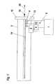
- Fig. 1shows a movable furniture part, a drawer or a drawer 3 without the surrounding piece of furniture in which it is installed.
- the drawer 3has here, as is generally customary, a front panel 15 and a handle 16. Furthermore is on the drawer 3 shown in a side view a rail 14, which on its lower edge is designed as a rack.
- the leadership of the Drawer when opening or closingtakes place here, as in the prior art known, via the rail 14. This is not shown here in detail and can in be carried out in various ways.
- a drive unit 5is now arranged in such a way that the gear 13 driven by it in the attached to the guide rail 14 Rack engages.
- the drive unit 5has an electric motor preferably servo motor 6 and a gear 12.
- the drawer 3can by means of the drive unit 5 designed in this way both partially or completely opened and partially or completely closed.
- the drive unit 5is stationary attached to the furniture, not shown, surrounding the drawer.
- a position measuring device 4here as one in the rack engaging gear shown
- the arrangement according to the invention Force measuring device 2can be driven via a toothed wheel 17 engage the rack in the rail 14.
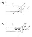
- the force measuring devicecan e.g. also on handle 16 or be arranged between the front panel 15 and the drawer 3.
- the force measuring device 2 between a front panel 15 and a part of the movable furniture part 3 directly adjoining itis arranged, or that the force measuring device between a front panel 15 and the Drive unit 5, preferably in the motor 6, is arranged.
- 5here is one Variant of the force measuring device 2 shown, which upon actuation of the handle 16 in vertical direction 21 is designed.
- 6shows a variant of the forces in horizontal direction 20 detected.
- a force measuring device 2Different force and accelerometers in question. This can e.g. Strain gauges, piezoelectric force transducers or electromagnetic Force measuring devices, e.g. Be moving coil instruments.
- the Force measuring device 2 and the position measuring device 4lead via suitable Lines of the control device 1 a force signal or position signal, from which in the Control device 1 a control signal for the drive unit 5 is calculated.
- a force signal or position signalfrom which in the Control device 1 a control signal for the drive unit 5 is calculated.
- the power transmission from the Drive unit 5, and the arrangement of the position measuring device 4 and the Force measuring device 2can also be in a different way than that shown here be realized.
- Drivesvia cables, toothed belts or otherwise driven guide rails.
- the control device 1 shown in FIG. 2first receives a force signal from the force measuring device 2 and a position signal from the position measuring device 4.
- the control device 1, the force measuring device 2 and the position measuring device 4can be designed in an analog, digital, partially analog and partially digital manner ,
- the analog force measuring device 2supplies an analog measurement signal to the analog input 18.
- Thistransmits the measurement signal to the setpoint calculation device 7 and to the comparator 19.
- the position signal generated by the position measuring device 4(for example, a sine-cosine encoder or incremental encoder) is fed to the actual-value calculation device 8. In this, the current actual position x I and the actual speed as well as the current actual value of the acceleration or deceleration of the drawer are calculated from the position signal.
- the actual value of the speed and the accelerationcan be calculated, for example, by single or double derivation of the actual value of the position over time. All three actual values calculated in this way are supplied to the controller module 9 and to the speed setpoint calculation device 11. The latter uses this to calculate the setpoint of the speed for each position, which must not be exceeded by the actual value of the speed at any position (see Fig. 4).
- the comparator 19receives information about the current Actual speed as well as the force signal, which is the information on the outside forces currently applied to the drawer.
- the comparator 19calculates a signal that tells the control module 9 whether pressure or tension is on the movable furniture part or the drawer is exercised.
- the Setpoint calculation device 7calculates the setpoint value from the force signal Accelerating the drawer. In general, both Frictional forces, which when opening or closing the drawer or the Movable furniture part act, as well as the adhesive forces, which are only in the end positions act on the drawer or the movable furniture part, taken into account.
- the calculationis to set a target value for the acceleration or deceleration To provide the acceleration or deceleration of an empty one Drawer or an empty movable piece of furniture with the measured externally equal forces. This can be done both through a calculation as well using a digital table in which measured accelerations or Delays of the empty furniture part depending on the measured from the outside this applied forces are stored, can be realized.
- a unfilled furniture partpreferably corresponds to the target value of the acceleration Acceleration value, which is without additional support from the drive unit would result from the external forces.
- a filled one Furniture partis the setpoint of acceleration calculated in such a way that by the filling additional forces to open or close by the Drive unit can be compensated.
- the values calculated as described aboveare fed to the control module 9.
- a control commandis generated in the control module 9, which the adaptation of the actual value of the acceleration or deceleration to the Setpoint used for acceleration or deceleration. This is beyond monitors that the actual value of the speed at no position of the movable Furniture part 3 exceeds the setpoint speed.
- Alternatively to Actual value / setpoint adjustment of the accelerationcan also be provided in the control module 9 be that the measured force applied externally to the movable furniture part 3 is adjusted to 0 by an appropriate acceleration or deceleration.
- the control command thus calculatedis fed to the drive unit controller 10. This can e.g.
- control device 1 shown in FIG. 2is only here a possible embodiment variant of a control method for the invention Arrangement.
- the components shown schematically in Fig. 2can be both an integrated component as well as an arrangement of various separate Components be formed.
- the device according to the invention shown schematically in FIGS. 1 and 2serves supporting both the closing and opening movements of the movable furniture part.
- the delay phasecan be such that the Servo assist effect is disabled from a custom position and the movable furniture part with the same kinematic parameters End position moved (forced guidance).
- FIG. 3shows the forces of a typical opening process for an empty (solid line) and a filled (dashed line) drawer in an arbitrarily selected calculation example.
- an external actuation force 20 of 8 N for acceleration or an actuation force of 2 N for decelerationis necessary (solid line).
- an external actuation force of 53 N for acceleration or 47 N for decelerationis required without servo assistance (dashed line).
- 3is based on a constant frictional force of 3 N, a non-existing locking force of the guide system of 0 N, a desired acceleration / deceleration of the drawer of 1 m / s 2 and a dead weight of the drawer of 5 kg.
- the mass of the filling materialis 45 kg.
- the drawerbehaves like an unloaded system (solid line), since the externally acting actuating force 20 is converted directly into a target value for the acceleration for the drive unit. This ensures that the filled drawer 3 also experiences an acceleration or a deceleration of 1 m / s 2 at 8 N actuating force 20. Without this support from the drive unit 5, the filled drawer would only experience an acceleration of 0.1 m / s 2 with the values used in the above calculation example if it were accelerated or decelerated with an actuating force of 8 N.
- the externally applied actuating force F Bis plotted as a function of the actual position x I of the drawer.
- FIG. 4shows an example of a curve of the target value V S of the speed calculated for a specific movement state of the movable furniture part.
- This setpoint curve calculated in this wayis used by the control device 1 to ensure that the movable furniture part comes to a standstill in the end positions (0 or x M ) and thus incorrect operation is not possible.
- the ramp shown in FIG. 4is calculated so that the maximum achievable speed decreases linearly to zero from a certain position.
- corresponding setpoint value curvesare preferably stored digitally.
- a switching thresholdcan be provided during the control process, wherein if the actuating force 20 in the direction 20 or 21 is smaller than the switching threshold, the movable furniture part is decelerated with a user-defined delay value.
- This switching thresholdcan be calculated, for example, from the frictional force of the empty, movable furniture part, but can also be determined using other criteria.
- the control device 1ensures that the maximum speed of the movable furniture part at any position is always less than or equal to the setpoint value V S of the speed.
Landscapes
- Engineering & Computer Science (AREA)
- Mechanical Engineering (AREA)
- Drawers Of Furniture (AREA)
- Power-Operated Mechanisms For Wings (AREA)
Abstract
Description
Translated fromGermanDie vorliegende Erfindung betrifft eine Anordnung mit einem bewegbaren Möbelteil,insbesondere mit einer Schublade, oder dergleichen mit einer Antriebseinheit und miteiner Regeleinrichtung zur Regelung der Antriebseinheit.The present invention relates to an arrangement with a movable furniture part,in particular with a drawer, or the like with a drive unit and witha control device for controlling the drive unit.
Derartige Anordnungen sind grundsätzlich bereits bekannt. Die deutsche PatentschriftDE 1 017 351 beschreibt eine Einrichtung zum Ausziehen oder Einschieben vonSchubladen in Möbel, die durch eine mittels korpusseitigen Drucktasten angesteuerteAntriebseinheit aus- bzw. einziehbar sind. Mit Hilfe der als Drucktasten ausgebildetenAuslöseeinrichtung ist jede mögliche Positionierung der Schublade zwischen dervollständig eingeschobenen und der vollständig herausgezogenen Position möglich.Die österreichische Patentschrift AT 398 513 B beschreibt eine Schubladenführungsgarnitur,deren Antrieb durch einen an der Frontblende der Schublade angeordnetenkapazitiven Tastschalter angesteuert ist. Durch Berührung des Tastschalters fährt dieSchublade ein bzw. aus. Die europäische Patentanmeldung EP 0 957 225 A1 enthälteine Vorrichtung zum Öffnen einer mit einer Antriebseinheit versehenen Schublade,wobei die Antriebseinheit durch ein als Tastschalter ausgeführtes Auslöseelementangesteuert ist. Die beiden zuletzt genannten Veröffentlichungen zeigen jeweils einAuslöseelement, das zwei Schaltzustände kennt. Folglich ist nach einem einmalerfolgten Ausziehvorgang bei Betätigung des Auslöseelements nur die Auslösung desentgegengesetzten Vorgangs möglich.Such arrangements are basically already known. The German patent specificationDE 1 017 351 describes a device for pulling out or pushing inDrawers in furniture that are controlled by a push button on the cabinet sideDrive unit can be extended or retracted. With the help of trained as push buttonsTrigger device is any possible positioning of the drawer between thefully retracted and fully withdrawn position possible.The Austrian patent AT 398 513 B describes a drawer slide set,whose drive is arranged on the front panel of the drawercapacitive push button switch is controlled. By touching the key switch, theDrawer on or off. The European
Aufgabe der vorliegenden Erfindung ist es nun, eine gattungsgemäße Anordnung zuschaffen, die ein intuitiveres Bedienen eines durch eine Antriebseinheit angetriebenenbewegbaren Möbelteiles ermöglicht.The object of the present invention is now to provide a generic arrangementcreate a more intuitive operation of a driven by a drive unitMovable furniture part allows.
Dies wird erfindungsgemäß dadurch erreicht, dass die Anordnung eine, vorzugsweiseanaloge, Kraftmesseinrichtung aufweist, wobei die Kraftmesseinrichtung ein für vonaußen an das bewegbare Möbelteil angelegte Kräfte charakteristisches Kraftsignalerzeugt, welches der Regeleinrichtung zuführbar ist.This is achieved according to the invention in that the arrangement is one, preferablyAnalogous, force measuring device, the force measuring device one forCharacteristic force signal applied to the outside of the movable furniture partgenerated, which can be fed to the control device.
Erfindungsgemäß ist somit eine Anordnung zur Verfügung gestellt, welche wie einübliches, nicht zusätzlich angetriebenes bewegbares Möbelteil betätigt werden kann.Mittels der Kraftmesseinrichtung wird erfindungsgemäß ein Kraftsignal erzeugt, welches den Betätigungswunsch des Benutzers an die Regeleinrichtung weiterleitet.Hieraus berechnet die Regeleinrichtung ein Regelsignal, welches die Unterstützungder vom Benutzer gewünschten Bewegung des bewegbaren Möbelteils durch dieAntriebseinheit ermöglicht. In dieser Weise wird die vom Benutzer gewünschteBewegung unterstützt, wobei gleichzeitig die intuitiv bekannte Vorgehensweise beimÖffnen oder Schließen eines bewegbaren Möbelteils für den Benutzer voll erhaltenbleibt.According to the invention, an arrangement is thus provided which is like anusual, not additionally driven movable furniture part can be operated.According to the invention, a force signal is generated by means of the force measuring device,which forwards the user's request for actuation to the control device.From this, the control device calculates a control signal, which is the supportthe movement of the movable furniture part desired by the user through theDrive unit enables. In this way, the one desired by the userMovement supports, while at the same time the intuitively known procedure forFull opening or closing of a movable piece of furniture for the userremains.
Besonders günstig ist es hierbei, dass das Kraftsignal sowohl die Information über denBetrag als auch über die Richtung, vorzugsweise über die Richtungskomponenteparallel zur Auszugsrichtung des bewegbaren Möbelteils, der von außen an denbewegbaren Möbelteil angelegten Kräfte beinhaltet. In dieser Variante ist somitvorgesehen, dass von der Regeleinrichtung mittels der Kraftmesseinrichtung erkanntwird, ob Druck oder Zug auf den bewegbaren Möbelteil ausgeübt wird. Hierdurch kanndie Regeleinrichtung entscheiden, ob der bewegbare Möbelteil geöffnet, geschlossen,beschleunigt oder verzögert werden soll. Darüber hinaus ist es durch die Messung desBetrages der von außen an den bewegbaren Möbelteil angelegten Kräfte auch möglichzu bestimmen, wie stark dieser beim Öffnen oder Schließen beschleunigt oderverzögert werden soll.It is particularly favorable here that the force signal contains both the information about theAmount as well as the direction, preferably via the direction componentparallel to the extension direction of the movable furniture part, which from the outside to theincludes movable forces applied forces. So in this variantprovided that recognized by the control device by means of the force measuring devicewhether pressure or tension is exerted on the movable furniture part. This canthe control device decides whether the movable furniture part is open, closed,should be accelerated or decelerated. In addition, it is by measuring theAmount of external forces applied to the movable furniture part is also possibleto determine how much this accelerates when opening or closingshould be delayed.
Des weiteren ist es günstig, dass die Anordnung mindestens einePositionsmesseinrichtung aufweist, welche ein für den Öffnungszustand desbewegbaren Möbelteils charakteristisches und der Regeleinrichtung zuführbaresPositionssignal erzeugt. Das so zur Verfügung gestellte Positionssignal kann derBerechnung der momentanen Istposition und/oder der momentanen Istgeschwindigkeitund/oder des momentanen Istwertes der Beschleunigung oder Verzögerung desbewegbaren Möbelteils als Funktion der gemessenen Position dienen. Dies wirdgünstigerweise dadurch realisiert, dass die Regeleinrichtung eineIstwertberechnungseinrichtung aufweist.Furthermore, it is favorable that the arrangement has at least oneHas position measuring device which for the opening state of theMovable furniture part characteristic and feedable to the control devicePosition signal generated. The position signal made available in this way canCalculation of the current actual position and / or the current actual speedand / or the current actual value of the acceleration or deceleration of themovable furniture part serve as a function of the measured position. this willConveniently realized in that the control deviceHas actual value calculation device.
In einer günstigen Variante ist des weiteren vorgesehen, dass die Regeleinrichtungeine Sollwertberechnungseinrichtung aufweist, welche aus dem von derKraftmesseinrichtung erzeugten Kraftsignal einen Sollwert für die Beschleunigung oderdie Verzögerung des bewegbaren Möbelteils berechnet, wobei eine besondersbevorzugte Ausgestaltungsform wiederum vorsieht, dass der Sollwert für die Beschleunigung oder die Verzögerung vom Beladungszustand des bewegbarenMöbelteils unabhängig ist. Durch diese Ausgestaltung wird erreicht, dass derbewegbare Möbelteil unabhängig von seiner Befüllung bei Anlegen einer bestimmtenäußeren Kraft an das bewegbare Möbelteil immer mit der gleichen Beschleunigungoder Verzögerung bewegt wird. Dies gibt dem Benutzer das Gefühl, dass derbewegbare Möbelteil scheinbar unabhängig von seiner Befüllung immer die gleicheMasse besitzt und resultiert darin, dass das Öffnen oder Schließen eines vollständiggefüllten bewegbaren Möbelteils sich für den Benutzer in der gleichen Weise anfühltund mit dem gleichen Kraftaufwand verbunden ist wie das Öffnen oder Schließen einesleeren bewegbaren Möbelteils.In a favorable variant it is further provided that the control devicehas a setpoint calculation device, which from theForce measuring device generated a target value for the acceleration orthe delay of the movable furniture part is calculated, one particularlypreferred embodiment in turn provides that the target value for theAcceleration or deceleration from the loaded state of the movableFurniture part is independent. This configuration ensures that themovable furniture part regardless of its filling when creating a certainexternal force on the movable furniture part always with the same accelerationor delay is moved. This gives the user the feeling that theMovable furniture part always the same regardless of how it is filledBulk owns and results in the opening or closing of one completelyfilled movable furniture part feels to the user in the same wayand involves the same amount of effort as opening or closing oneempty movable furniture part.
Dies kann günstigerweise realisiert werden, indem die Regeleinrichtung einRegelmodul aufweist, welches den Istwert der Beschleunigung oder Verzögerung anden Sollwert der Beschleunigung oder Verzögerung durch Weitergabe einesRegelsignals an einen Antriebseinheitregler anpaßt, wobei der Antriebseinheitregler dieAntriebseinheit ansteuert. Durch diesen Istwert/Sollwert-Abgleich der Beschleunigungwird erreicht, dass die Antriebseinheit die Bewegung des bewegbaren Möbelteilsgezielt in der Weise unterstützt, dass sich auch ein gefüllter bewegbarer Möbelteil fürden Benutzer scheinbar wie ein leerer bewegbarer Möbelteil betätigen läßt.This can conveniently be achieved by using the control deviceControl module which indicates the actual value of the acceleration or decelerationthe setpoint of acceleration or deceleration by passing on aAdapts control signal to a drive unit controller, the drive unit controllerControls drive unit. Through this actual value / setpoint adjustment of the accelerationis achieved that the drive unit stops the movement of the movable furniture partspecifically supports in such a way that there is also a filled, movable furniture part forlets the user seem to operate like an empty movable piece of furniture.
Um ein rechtzeitiges Abbremsen des bewegbaren Möbelteils vor dem Erreichen seinerEndlage beim Öffnen oder Schließen zu gewährleisten, ist es vorteilhaft, wenn dieRegeleinrichtung eine Geschwindigkeitsollwertberechnungseinrichtung aufweist,welche einen von der Istposition abhängigen Sollwert der Geschwindigkeit berechnet,wobei das Regelmodul dem Antriebseinheitregler einen Steuerbefehl zur Verringerungdes Istwertes der Beschleunigung oder zur Erhöhung des Istwertes der Verzögerungzusendet, wenn der Istwert der Geschwindigkeit den Sollwert der Geschwindigkeit fürdie momentane Position überschreitet. In dieser Ausführungsform werden somit dievom Benutzer des bewegbaren Möbelteils durch Drücken oder Ziehen an diesemausgeübten Steuersignale in der Weise kontrolliert, dass der bewegbare Möbelteil inder vollständig ausgefahren und in der vollständig eingeschobenen Position zur Ruhekommt. Hierdurch werden unbeabsichtigte Beschädigungen der gesamten Einrichtungverhindert.To slow down the movable furniture part before reaching itTo ensure end position when opening or closing, it is advantageous if theControl device has a speed setpoint calculation device,which calculates a setpoint value of the speed dependent on the actual position,the control module giving the drive unit controller a control command to reducethe actual value of the acceleration or to increase the actual value of the decelerationsends if the actual value of the speed is the setpoint of the speed forexceeds the current position. In this embodiment, theby the user of the movable furniture part by pressing or pulling on itControl signals exercised in such a way that the movable furniture part inthe fully extended and in the fully retracted position to restcomes. This will cause accidental damage to the entire facilityprevented.
Bei einer weiteren vorteilhaften Ausführungsform der Erfindung kann vorgesehen sein,dass die Kraftmesseinrichtung zwischen einem Frontpaneel und einem daran direktanschließenden Teil des bewegbaren Möbelteils angeordnet ist. Es kann auchvorgesehen sein, dass die Kraftmesseinrichtung zwischen einem Frontpaneel und derAntriebseinheit, vorzugsweise im Motor, angeordnet ist.In a further advantageous embodiment of the invention,that the force measuring device between a front panel and one directly on itadjoining part of the movable furniture part is arranged. It can alsobe provided that the force measuring device between a front panel and theDrive unit, preferably in the engine.
Weitere Einzelheiten und Merkmale der vorliegenden Erfindung ergeben sich aus dernachfolgenden Figurenbeschreibung. Dabei zeigt:
- Fig. 1
- eine schematisierte Seitenansicht auf eine erfindungsgemäßeAusführungsform mit einer Schublade,
- Fig. 2
- ein Schema zu einer Möglichkeit der Ausbildung der Regeleinrichtung,
- Fig. 3
- ein Vergleich des Kraftbedarfs beim Betätigen einer rein manuellbetriebenen Schublade im leeren und im gefüllten Zustand,
- Fig.4
- eine beispielhafte Darstellung zum Sollwert der Geschwindigkeit alsFunktion der momentanen Position und
- Fig. 5 und 6
- spezielle Ausführungsvarianten der Kraftmesseinrichtung
- Fig. 1
- 2 shows a schematic side view of an embodiment according to the invention with a drawer,
- Fig. 2
- a scheme for a possibility of training the control device,
- Fig. 3
- a comparison of the power requirement when operating a purely manually operated drawer in the empty and in the filled state,
- Figure 4
- an exemplary representation of the setpoint value of the speed as a function of the current position and
- 5 and 6
- special design variants of the force measuring device
Fig. 1 zeigt als bewegbaren Möbelteil eine Schublade oder einen Schubkasten 3 ohnedas umgebende Möbelstück, in dem sie/er eingebaut ist. Die Schublade 3 weisthierbei, wie allgemein üblich, ein Frontpaneel 15 sowie einen Griff 16 auf. Des weiterenist an der in einer Seitenansicht dargestellten Schublade 3 eine Schiene 14, welche anihrer Unterkante als Zahnstange ausgebildet ist, angeordnet. Die Führung derSchublade beim Öffnen oder Schließen erfolgt hierbei, wie beim Stand der Technikbekannt, über die Schiene 14. Dies ist hier nicht genauer dargestellt und kann inverschiedensten Arten und Weisen ausgeführt sein. Zur Unterstützung der ÖffnungsundSchließbewegung ist nun eine Antriebseinheit 5 in der Weise angeordnet, dassdas von ihr angetriebene Zahnrad 13 in die an der Führungsschiene 14 angebrachteZahnstange eingreift. Die Antriebseinheit 5 weist hierbei einen elektrischen Motorvorzugsweise Servomotor 6 sowie ein Getriebe 12 auf. Die Schublade 3 kann mittelsder so gestalteten Antriebseinheit 5 sowohl teilweise oder vollständig geöffnet als auchteilweise oder vollständig geschlossen werden. Hierbei ist die Antriebseinheit 5 ortsfestam nicht weiter dargestellten, die Schublade umgebenden Möbel angebracht. Zur Bestimmung eines Positionssignals, welches den Öffnungs- bzw. Schließzustand derSchublade angibt, ist eine Positionsmesseinrichtung 4 (hier als ein in die Zahnstangeeingreifendes Zahnrad dargestellt) vorgesehen.Fig. 1 shows a movable furniture part, a drawer or a
Zur Bestimmung des Betrages und der Richtung der von außen an die Schublade 3angreifenden Kräfte 20 weist die Anordnung erfindungsgemäß eineKraftmesseinrichtung 2 auf. Diese Kraftmesseinrichtung 2 kann über ein Zahnrad 17 indie Zahnstange in der Schiene 14 eingreifen. Alternativ hierzu sind jedoch auchzahlreiche andere Anordnungs- und Ausbildungsformen der erfindungsgemäßenKraftmesseinrichtung möglich. So kann die Kraftmesseinrichtung z.B. auch am Griff 16oder zwischen Frontpaneel 15 und Schublade 3 angeordnet sein. Allgemein kannvorgesehen sein, dass die Kraftmesseinrichtung 2 zwischen einem Frontpaneel 15 undeinem daran direkt anschließenden Teil des bewegbaren Möbelteils 3 angeordnet ist,oder dass die Kraftmesseinrichtung zwischen einem Frontpaneel 15 und derAntriebseinheit 5, vorzugsweise im Motor 6, angeordnet ist. In Fig. 5 ist hierbei eineVariante der Kraftmesseinrichtung 2 gezeigt, welche auf Betätigung des Griffes 16 invertikaler Richtung 21 ausgelegt ist. In Fig. 6 ist eine Variante gezeigt, welche Kräfte inhorizontaler Richtung 20 detektiert. Als Kraftmesseinrichtung 2 kommenunterschiedlichste Kraft- bzw. Beschleunigungsmesser in Frage. Dies können z.B.Dehnungsmeßstreifen, piezoelektrische Kraftaufnehmer oder elektromagnetischeKraftmesseinrichtungen, wie z.B. Tauchspuleninstrumente sein. DieKraftmesseinrichtung 2 sowie die Positionsmesseinrichtung 4 führen über geeigneteLeitungen der Regeleinrichtung 1 ein Kraftsignal bzw. Positionssignal zu, woraus in derRegeleinrichtung 1 ein Ansteuersignal für die Antriebseinheit 5 berechnet wird. Bei derMessung der von außen an die Schublade angreifenden Kräfte 20 wird in der Regelwie in der in Fig. 1 dargestellten üblichen Ausführungsform nur die inBewegungsrichtung der Schublade 3 verlaufende horizontale Kraftkomponente (durchdie Pfeilrichtung 20 gekennzeichnet) gemessen, da die vertikal angreifendenKraftkomponenten durch die Führungsschiene auf entsprechende nach dem Stand derTechnik ausgebildete Lager übertragen werden. Die Kraftübertragung von derAntriebseinheit 5, sowie die Anordnung der Positionsmesseinrichtung 4 und derKraftmesseinrichtung 2 können auch in anderer als der hier dargestellten Weiserealisiert sein. In Frage kommen hierzu z.B. Antriebe über Seilzüge, Zahnriemen oderanderweitig angetriebene Führungsschienen.To determine the amount and the direction of the outside of the
Die in Fig. 2 dargestellte Regeleinrichtung 1 erhält zunächst ein Kraftsignal von derKraftmesseinrichtung 2 sowie ein Positionssignal von der Positionsmesseinrichtung 4.Die Regeleinrichtung 1, die Kraftmesseinrichtung 2 sowie die Positionsmesseinrichtung4 können sowohl analog als auch digital als auch teilweise analog und teilweise digitalausgebildet sein. Im dargestellten Beispiel führt die analoge Kraftmesseinrichtung 2 einanaloges Meßsignal dem Analogeingang 18 zu. Dieser überträgt das Meßsignal zurSollwertberechnungseinrichtung 7 sowie zum Komparator 19. Das von derPositionsmesseinrichtung 4 (z.B. als Sinus-Cosinus-Geber oder Incremental-Geberausgebildeter Encoder) erzeugte Positionssignal wird derIstwertberechnungseinrichtung 8 zugeführt. In dieser wird aus dem Positionssignalsowohl die momentane Istposition xI und Istgeschwindigkeit als auch der momentaneIstwert der Beschleunigung oder Verzögerung der Schublade berechnet. Der Istwertder Geschwindigkeit und der Beschleunigung können dabei z.B. durch einfache bzw.zweifache Ableitung des Istwertes der Position nach der Zeit berechnet werden. Alledrei so berechneten Istwerte werden dem Reglermodul 9 sowie derGeschwindigkeitssollwertberechnungseinrichtung 11 zugeführt. Letztere berechnethieraus für jede Position den Sollwert der Geschwindigkeit, welcher an keiner Positionvom Istwert der Geschwindigkeit übertroffen werden darf (siehe hierzu Fig. 4).The
Der Komparator 19 erhält sowohl Informationen über die momentaneIstgeschwindigkeit als auch das Kraftsignal, welches die Information über die äußerlichan die Schublade momentan angelegten Kräfte beinhaltet. Der Komparator 19berechnet hierbei ein Signal, das dem Regelmodul 9 mitteilt, ob Druck oder Zug aufdas bewegbare Möbelteil bzw. die Schublade ausgeübt wird. DieSollwertberechnungseinrichtung 7 berechnet aus dem Kraftsignal den Sollwert derBeschleunigung der Schublade. Hierbei werden im allgemeinen sowohl dieReibungskräfte, welche beim Öffnen oder Schließen auf die Schublade bzw. dasbewegbare Möbelteil wirken, als auch die Haftkräfte, welche nur in den Endpositionenauf die Schublade bzw. das bewegbare Möbelteil wirken, berücksichtigt. Ziel derBerechnung ist es, einen Sollwert der Beschleunigung bzw. Verzögerung zurVerfügung zu stellen, der der Beschleunigung bzw. Verzögerung einer leerenSchublade bzw. eines leeren bewegbaren Möbelteils bei den gemessenen äußerlichanliegenden Kräften gleichkommt. Dies kann sowohl durch eine Berechnung als auchmittels einer digitalen Tabelle, in der gemessene Beschleunigungen bzw.Verzögerungen des leeren Möbelteiles in Abhängigkeit der gemessenen von außen an dieses angelegten Kräfte gespeichert sind, realisiert werden. Im Falle einesnichtgefüllten Möbelteils entspricht der Sollwert der Beschleunigung vorzugsweise demBeschleunigungswert, welcher sich ohne zusätzliche Unterstützung der Antriebseinheitdurch die äußerlich angelegten Kräfte ergeben würde. Im Falle eines gefülltenMöbelteils ist der Sollwert der Beschleunigung in der Weise berechnet, dass die durchdie Befüllung zusätzlich aufzuwendenden Kräfte zum Öffnen oder Schließen durch dieAntriebseinheit kompensiert werden. Die - wie oben geschildert - berechneten Wertewerden dem Regelmodul 9 zugeführt. Im Regelmodul 9 wird ein Steuerbefehl erzeugt,welcher der Anpassung des Istwertes der Beschleunigung oder Verzögerung an denSollwert der Beschleunigung oder Verzögerung dient. Hierbei wird darüber hinausüberwacht, dass der Istwert der Geschwindigkeit an keiner Position des bewegbarenMöbelteils 3 den Sollwert der Geschwindigkeit überschreitet. Alternativ zumIstwert/Sollwert Abgleich der Beschleunigung kann im Regelmodul 9 auch vorgesehensein, dass die gemessene äußerlich an das bewegbare Möbelteil 3 angelegte Kraftdurch eine entsprechende Beschleunigung oder Verzögerung auf 0 abgeglichen wird.Der so berechnete Steuerbefehl wird dem Antriebseinheitsregler 10 zugeführt. Dieserkann z.B. als Servomotor-Regelmodul, vozugsweise mit kaskadiertem Lageregler,Geschwindigkeitsregler und Stromregler ausgebildet sein und dient der Ansteuerungdes Motors bzw. Servomotors 6 der Antriebseinheit 5. Das hierzu notwendigeAnsteuersignal kann z.B. ein pulsweitenmodulierter Strom, wie beim Stand der Technikfür Servoregler bekannt, sein. Die in Fig. 2 gezeigte Regeleinrichtung 1 ist hierbei nureine mögliche Ausführungsvariante eines Regelverfahrens für die erfindungsgemäßeAnordnung. Die in Fig. 2 schematisch dargestellten Komponenten können sowohl alsein integriertes Bauelement als auch als eine Anordnung verschiedener separaterKomponenten ausgebildet sein.The
Die in den Fig. 1 und 2 schematisch dargestellte erfindungsgemäße Einrichtung dientsowohl der Unterstützung der Schließ- als auch der Öffnungsbewegung desbewegbaren Möbelteils. Beim Schließvorgang ergeben sich dieBeschleunigungsphasen und Verzögerungsphasen in entsprechender Weise wie beimÖffnungsvorgang. Die Verzögerungsphase kann jedoch so erfolgen, dass derServounterstützungseffekt ab einer benutzerdefinierten Position deaktiviert wird undder bewegbare Möbelteil sich mit immer gleichen kinematischen Parametern in dieEndlage bewegt (Zwangsführung).The device according to the invention shown schematically in FIGS. 1 and 2 servessupporting both the closing and opening movements of themovable furniture part. When closing, the resultAcceleration phases and deceleration phases in the same way as forOpening process. However, the delay phase can be such that theServo assist effect is disabled from a custom position andthe movable furniture part with the same kinematic parametersEnd position moved (forced guidance).
In Fig. 3 sind in einem beliebig herausgegriffenen Rechenbeispiel die Kräfte einestypischen Öffnungsvorgangs für eine leere (durchgezogene Linie) und eine gefüllte(gestrichelte Linie) Schublade dargestellt. Um eine Beschleunigung und eineVerzögerung von jeweils 1m/s2 für die Schublade zu erreichen, ist im Fall derunbeladenen Schublade 3 eine externe Betätigungskraft 20 von 8 N zurBeschleunigung bzw. eine Betätigungskraft von 2 N zur Verzögerung notwendig(durchgezogene Linie). Um bei gefüllter Schublade die gleichen Beschleunigungs- undVerzögerungswerte für eine gefüllte Schublade zu erreichen, ist ohneServounterstützung eine externe Betätigungskraft von 53 N zur Beschleunigung bzw.von 47 N zur Verzögerung notwendig (strichlierte Linie). Diesem in Fig. 3 gezeigtenRechenbeispiel sind eine gleichbleibende Reibungskraft von 3 N, eine nichtvorhandene Zuhaltekraft des Führungssystems von 0 N, eine gewünschteBeschleunigung/Verzögerung der Lade von 1 m/s2 und eine Eigenmasse derSchublade von 5 kg zugrunde gelegt. Die Masse des Füllgutes beträgt 45 kg.3 shows the forces of a typical opening process for an empty (solid line) and a filled (dashed line) drawer in an arbitrarily selected calculation example. In order to achieve an acceleration and a deceleration of 1m / s2 for the drawer, in the case of the unloaded
Durch die in Fig. 1 und 2 illustrierte erfindungsgemäße Anordnung verhält sich dieSchublade jedoch wie ein unbeladenes System (durchgezogene Linie), da dieäußerlich angreifende Betätigungskraft 20 direkt in einen Sollwert der Beschleunigungfür die Antriebseinheit umgerechnet wird. Hierdurch wird erreicht, dass bereits bei 8 NBetätigungskraft 20 die gefüllte Schublade 3 durch Unterstützung ebenfalls eineBeschleunigung bzw. eine Verzögerung von 1 m/s2 erfährt. Ohne diese Unterstützungdurch die Antriebseinheit 5 würde die gefüllte Schublade bei den im oben angeführtenBerechnungsbeispiel zugrundegelegten Werten lediglich eine Beschleunigung von 0,1m/s2 erfahren, wenn sie mit einer Betätigungskraft von 8 N beschleunigt bzw. verzögertwürde. Im in Fig. 3 dargestellten Beispiel ist die äußerlich angelegte BetätigungskraftFB in Abhängigkeit der Istposition xI der Schublade aufgetragen.Due to the arrangement according to the invention illustrated in FIGS. 1 and 2, however, the drawer behaves like an unloaded system (solid line), since the externally acting actuating
Fig. 4 zeigt ein Beispiel einer für einen bestimmten Bewegungszustand desbewegbaren Möbelteils berechneten Kurve des Sollwertes VS der Geschwindigkeit.Diese so berechnete Sollwertkurve dient der Regeleinrichtung 1 dazu, sicherzustellen,dass das bewegbare Möbelteil in den Endlagen (0 oder xM) zum Stillstand kommt undsomit keine Fehlbedienung möglich ist. Beim Öffnen oder Schließen wird die in Fig. 4dargestellte Rampe so berechnet, dass die maximal erreichbare Geschwindigkeit abeiner bestimmten Position linear auf Null abnimmt. Alternativ zur Berechnung des Sollwertes der Geschwindigkeit kann auch vorgesehen sein, dass entsprechendeSollwertkurven vorzugsweise digital abgespeichert sind.FIG. 4 shows an example of a curve of the target value VS of the speed calculated for a specific movement state of the movable furniture part. This setpoint curve calculated in this way is used by the
Zusätzlich kann eine Schaltschwelle beim Regelvorgang vorgesehen sein, wobei,wenn die Betätigungskraft 20 in Richtung 20 oder 21 kleiner als die Schaltschwelle ist,das bewegbare Möbelteil mit einem benutzerdefinierten Verzögerungswert verzögertwird. Diese Schaltschwelle kann z.B. aus der Reibungskraft des leeren bewegbarenMöbelteils errechnet, jedoch auch mittels anderer Gesichtspunkte ermittelt werden.Insgesamt sorgt die Regeleinrichtung 1 dafür, dass die Höchstgeschwindigkeit desbewegbaren Möbelteils an jeder Position immer kleiner oder gleich dem Sollwert VS derGeschwindigkeit ist.In addition, a switching threshold can be provided during the control process, wherein if the actuating
Claims (11)
Translated fromGermanApplications Claiming Priority (2)
| Application Number | Priority Date | Filing Date | Title |
|---|---|---|---|
| AT20372001 | 2001-12-27 | ||
| AT0203701AAT413631B (en) | 2001-12-27 | 2001-12-27 | ARRANGEMENT WITH A MOVABLE FURNITURE, WITH A DRIVE UNIT AND WITH A CONTROL DEVICE |
Publications (2)
| Publication Number | Publication Date |
|---|---|
| EP1323363A1true EP1323363A1 (en) | 2003-07-02 |
| EP1323363B1 EP1323363B1 (en) | 2008-02-20 |
Family
ID=3689693
Family Applications (1)
| Application Number | Title | Priority Date | Filing Date |
|---|---|---|---|
| EP02027227AExpired - LifetimeEP1323363B1 (en) | 2001-12-27 | 2002-12-06 | Device with a movable furniture part, including drive unit and control device |
Country Status (7)
| Country | Link |
|---|---|
| US (1) | US7633258B2 (en) |
| EP (1) | EP1323363B1 (en) |
| JP (1) | JP2003334120A (en) |
| CN (1) | CN100353886C (en) |
| AT (2) | AT413631B (en) |
| DE (1) | DE50211731D1 (en) |
| ES (1) | ES2299549T3 (en) |
Cited By (29)
| Publication number | Priority date | Publication date | Assignee | Title |
|---|---|---|---|---|
| EP1374732A1 (en)* | 2002-06-27 | 2004-01-02 | Julius Blum Gesellschaft m.b.H. | Auxiliary pushing mechanism |
| WO2004100717A1 (en)* | 2003-05-19 | 2004-11-25 | Julius Blum Gmbh | Method for driving a movable part of a piece of furniture |
| WO2005058092A1 (en) | 2003-12-17 | 2005-06-30 | Julius Blum Gmbh | Displaceable piece of furniture |
| DE102004045567A1 (en)* | 2004-09-17 | 2006-04-06 | Küster Automotive Door Systems GmbH | Adjustment device for adjusting, in particular for translational displacement, of a furniture part |
| WO2007009133A1 (en)* | 2005-07-20 | 2007-01-25 | Julius Blum Gmbh | Drive for a mobile furniture part |
| WO2007042266A1 (en)* | 2005-10-13 | 2007-04-19 | Küster Automotive Door Systems GmbH | Device and method for closing or opening and closing at least one drawer, flap, door, or similar |
| DE202006005577U1 (en)* | 2006-04-04 | 2007-08-16 | Grass Gmbh | Device for moving a first furniture part relative to a second furniture part |
| DE202006005578U1 (en)* | 2006-04-04 | 2007-08-16 | Grass Gmbh | Device for moving a first furniture part relative to a second furniture part and furniture |
| DE202006005579U1 (en)* | 2006-04-04 | 2007-08-16 | Grass Gmbh | Device for influencing the movement of furniture parts and furniture that are movable relative to one another |
| WO2007092969A1 (en)* | 2006-02-15 | 2007-08-23 | Julius Blum Gmbh | Arrangement with at least two driven furniture pieces |
| DE202006006181U1 (en)* | 2006-04-18 | 2007-08-30 | Paul Hettich Gmbh & Co. Kg | Furniture |
| WO2007098515A3 (en)* | 2006-03-03 | 2007-10-25 | Blum Gmbh Julius | Assembly comprising electric drive units for drawers |
| DE202006012087U1 (en)* | 2006-08-04 | 2007-12-20 | Grass Gmbh | Device for moving a first furniture part relative to a second furniture part and furniture |
| WO2008113402A1 (en)* | 2007-03-21 | 2008-09-25 | Linrot Holding Ag | Piece of furniture |
| WO2009012507A1 (en) | 2007-07-24 | 2009-01-29 | Julius Blum Gmbh | Furniture drive |
| EP2090190A1 (en)* | 2008-02-18 | 2009-08-19 | Paul Hettich GmbH & Co. KG | Acoustic signal creation in furniture with electromechanical drive device |
| FR2937369A1 (en)* | 2008-10-17 | 2010-04-23 | Bernard Loiseau Sa | Service-hatch device for use on partition in e.g. catering industry, has slide slidingly mounted through partition via glide, and obturator element preventing continuous passage of smoke from room to other places |
| RU2401034C2 (en)* | 2005-07-20 | 2010-10-10 | Юлиус Блум Гмбх | Drive for movable part of furniture |
| US7812561B2 (en) | 2006-04-04 | 2010-10-12 | Grass Gmbh | Device for controlling a movement of furniture parts which can be moved with respect to one another, and piece of furniture |
| US8005577B2 (en) | 2006-04-04 | 2011-08-23 | Grass Gmbh | Apparatus for controlling the movement of furniture parts which can be moved with respect to one another, and piece of furniture |
| US8026686B2 (en) | 2006-04-04 | 2011-09-27 | Grass Gmbh | Device for controlling the movement of a plurality of movable furniture parts and method for configuration of a device such as this, and piece of furniture |
| US8026685B2 (en) | 2006-04-04 | 2011-09-27 | Grass Gmbh | Device for controlling the movement of a plurality of moveable furniture parts, and a method for configuration of a device such as this, and piece of furniture |
| US8579392B2 (en) | 2005-04-28 | 2013-11-12 | Julius Blum Gmbh | Ejection device for a movable furniture part |
| EP2283293A4 (en)* | 2008-03-26 | 2015-06-10 | Lg Electronics Inc | CONTROL SYSTEM AND METHOD FOR REFRIGERATOR DRAWER |
| AT526352B1 (en)* | 2022-12-23 | 2024-02-15 | Blum Gmbh Julius | Arrangement comprising a fixed furniture part, a movable furniture part, a guide device and an electric drive device |
| AT526351A4 (en)* | 2022-12-23 | 2024-02-15 | Blum Gmbh Julius | Arrangement comprising a fixed furniture part, a movable furniture part, a guide device and an electric drive device |
| WO2024130279A1 (en) | 2022-12-23 | 2024-06-27 | Julius Blum Gmbh | Computer-assisted method for moving a movable furniture part, microcontroller, and computer programme product |
| WO2024130282A1 (en) | 2022-12-23 | 2024-06-27 | Julius Blum Gmbh | Assembly comprising a stationary furniture part, a movable furniture part, and a guide device |
| WO2024130283A1 (en) | 2022-12-23 | 2024-06-27 | Julius Blum Gmbh | Assembly comprising a fixed furniture part, a moveable furniture part, a guide device, an electrical drive device and an illumination means |
Families Citing this family (28)
| Publication number | Priority date | Publication date | Assignee | Title |
|---|---|---|---|---|
| AT413633B (en)* | 2004-08-16 | 2006-04-15 | Blum Gmbh Julius | RELEASE FOR MOVABLE FURNITURE PARTS |
| EP1870000B1 (en) | 2005-03-31 | 2014-01-01 | Thk Co., Ltd. | Movable body drive unit and automatic drawer device using the same |
| DE112007002274B4 (en) | 2006-09-27 | 2018-07-19 | Thk Co., Ltd. | Drawer device with auxiliary device |
| DE202007004337U1 (en) | 2007-03-21 | 2008-09-04 | Linrot Holding Ag | Electromotive furniture drive |
| US7823993B2 (en)* | 2007-04-03 | 2010-11-02 | Carefusion 303, Inc. | Piezo actuated slide latching mechanism |
| DE202007006301U1 (en)* | 2007-04-30 | 2008-03-20 | Grass Gmbh | Furniture and device for ejecting a furniture part, which is movably received on a fixed furniture part |
| AT505209B1 (en)* | 2007-05-07 | 2012-04-15 | Blum Gmbh Julius | DRIVE FOR A MOVABLE FURNITURE PART |
| US8061790B2 (en)* | 2007-12-20 | 2011-11-22 | General Electric Company | Powered drawer for an appliance |
| WO2009119921A1 (en)* | 2008-03-26 | 2009-10-01 | Lg Electronics Inc. | System and method for driving a drawer in a refrigerator |
| KR101380557B1 (en)* | 2008-03-26 | 2014-04-01 | 엘지전자 주식회사 | System and method for driving a drawer in a refrigerator |
| CN101981398B (en)* | 2008-03-26 | 2013-03-27 | Lg电子株式会社 | Refrigerator, system and method for driving a drawer of the refrigerator |
| US8217613B2 (en)* | 2008-03-26 | 2012-07-10 | Lg Electronics Inc. | System and method for driving a drawer of a refrigerator and refrigerator employing same |
| KR101441133B1 (en)* | 2008-03-26 | 2014-09-17 | 엘지전자 주식회사 | How to control the drawer drive of refrigerator |
| KR101592572B1 (en)* | 2009-03-20 | 2016-02-05 | 엘지전자 주식회사 | Refrigerator and its control method |
| KR101592571B1 (en)* | 2009-03-20 | 2016-02-05 | 엘지전자 주식회사 | A refrigerator for controlling refrigerator |
| KR101592575B1 (en)* | 2009-03-20 | 2016-02-05 | 엘지전자 주식회사 | Refrigerator |
| KR101592573B1 (en)* | 2009-03-20 | 2016-02-05 | 엘지전자 주식회사 | Refrigerator |
| KR101592574B1 (en)* | 2009-03-20 | 2016-02-05 | 엘지전자 주식회사 | A refrigerator for controlling refrigerator |
| KR20110024883A (en)* | 2009-09-03 | 2011-03-09 | 삼성전자주식회사 | Automatic door opening and closing device and refrigerator having same |
| DE202010014732U1 (en)* | 2010-10-28 | 2012-01-30 | Grass Gmbh | Device for moving a movably received furniture part and furniture |
| AT510549B1 (en)* | 2011-02-21 | 2012-05-15 | Blum Gmbh Julius | FURNITURE DRIVE |
| US9443371B2 (en)* | 2013-03-27 | 2016-09-13 | Aesynt Incorporated | Medication dispensing cabinet, computing device and associated method for measuring the force applied to a drawer |
| CN104490136A (en)* | 2014-12-15 | 2015-04-08 | 广西大学 | Automatic opening and closing drawer |
| DE102016212046A1 (en)* | 2016-07-01 | 2018-01-04 | Continental Automotive Gmbh | Method and device for detecting a force exerted by a part which is electrically adjustable with an electric motor on a force possibly applied thereto |
| CN111684222B (en)* | 2018-02-05 | 2022-03-08 | 三星电子株式会社 | Refrigerator with a door |
| US10413064B1 (en)* | 2018-09-26 | 2019-09-17 | Dong Guan Song Wei Electric Technology Co., Ltd. | Electric drawer with gesture sensing |
| KR102614492B1 (en)* | 2018-12-21 | 2023-12-15 | 엘지전자 주식회사 | Refrigerator |
| EP4251542A4 (en)* | 2020-11-25 | 2024-11-06 | Simplehuman LLC | BUILT-IN, ELECTRONICALLY MOVABLE WASTE BIN |
Citations (3)
| Publication number | Priority date | Publication date | Assignee | Title |
|---|---|---|---|---|
| DE1017351B (en) | 1956-03-16 | 1957-10-10 | Dr Otto A Becker | Device for pulling out and pushing in or in a desk. The like. Arranged drawers, drawers, pulls or the like. |
| AT398513B (en) | 1989-05-30 | 1994-12-27 | Blum Gmbh Julius | DRAWER GUIDE SET |
| EP0957225A1 (en) | 1998-05-11 | 1999-11-17 | bulthaup GmbH & Co. Küchensysteme | Device for the opening of a closure element |
Family Cites Families (19)
| Publication number | Priority date | Publication date | Assignee | Title |
|---|---|---|---|---|
| JPS55166763A (en)* | 1979-06-12 | 1980-12-26 | Tokyo Electric Co Ltd | Electronic cash register |
| JPH01185996A (en)* | 1988-01-21 | 1989-07-25 | Nec Corp | Cash drawer with linear motor |
| JP2873831B2 (en)* | 1989-04-14 | 1999-03-24 | カヤバ工業株式会社 | Power assist device |
| US5822707A (en)* | 1992-05-05 | 1998-10-13 | Automotive Technologies International, Inc. | Automatic vehicle seat adjuster |
| JPH0614819A (en) | 1992-06-30 | 1994-01-25 | Raifu Technol Kenkyusho | Slide mechanism |
| JP2709254B2 (en) | 1993-03-10 | 1998-02-04 | 富士通テン株式会社 | cabinet |
| DE4402899C1 (en)* | 1994-02-02 | 1995-08-17 | Dorma Gmbh & Co Kg | Operating procedure for operating a revolving door |
| US5716114A (en)* | 1996-06-07 | 1998-02-10 | Pyxis Corporation | Jerk-resistant drawer operating system |
| JPH0975150A (en) | 1995-09-07 | 1997-03-25 | Cleanup Corp | Hanging cabinet with lifting mechanism |
| JPH0995140A (en)* | 1995-10-02 | 1997-04-08 | Oi Seisakusho Co Ltd | Driving control device of motor-driven object for vehicle |
| JP3340622B2 (en)* | 1996-06-07 | 2002-11-05 | 本田技研工業株式会社 | Electric power sliding door device |
| US5774046A (en)* | 1996-06-13 | 1998-06-30 | Asmo Co., Ltd. | Power window apparatus with sensor failure detection |
| US5931532A (en)* | 1997-02-03 | 1999-08-03 | Kemmerer; Kenneth | Lift recliner chair with safety system |
| JPH119355A (en) | 1997-06-23 | 1999-01-19 | Yamaha Living Tec Kk | Elevating/lowering cabinet |
| JPH1189642A (en) | 1997-09-18 | 1999-04-06 | Matsushita Electric Ind Co Ltd | Operating force reduction device |
| GB2343371B (en) | 1998-11-03 | 2000-09-27 | Ulland Islwyn Watkins | Control of powered furniture |
| US6291957B1 (en)* | 1999-10-29 | 2001-09-18 | Meritor Light Vehicle Systems, Inc. | Obstruction sensing utilizing lateral forces on a moving window |
| JP2001199692A (en) | 2000-01-18 | 2001-07-24 | Matoba Denki Seisakusho:Kk | Elevating device |
| DE10048601A1 (en)* | 2000-10-27 | 2002-04-11 | Bosch Gmbh Robert | Motorised setting movement control method e.g. for automobile electric window or sunroof, involves operating electric drive motor with reduced power during motor run-up phase |
- 2001
- 2001-12-27ATAT0203701Apatent/AT413631B/ennot_activeIP Right Cessation
- 2002
- 2002-12-06ESES02027227Tpatent/ES2299549T3/ennot_activeExpired - Lifetime
- 2002-12-06DEDE50211731Tpatent/DE50211731D1/ennot_activeExpired - Lifetime
- 2002-12-06ATAT02027227Tpatent/ATE386451T1/enactive
- 2002-12-06EPEP02027227Apatent/EP1323363B1/ennot_activeExpired - Lifetime
- 2002-12-23USUS10/325,886patent/US7633258B2/ennot_activeExpired - Fee Related
- 2002-12-26JPJP2002377686Apatent/JP2003334120A/enactivePending
- 2002-12-27CNCNB021608512Apatent/CN100353886C/ennot_activeExpired - Fee Related
Patent Citations (3)
| Publication number | Priority date | Publication date | Assignee | Title |
|---|---|---|---|---|
| DE1017351B (en) | 1956-03-16 | 1957-10-10 | Dr Otto A Becker | Device for pulling out and pushing in or in a desk. The like. Arranged drawers, drawers, pulls or the like. |
| AT398513B (en) | 1989-05-30 | 1994-12-27 | Blum Gmbh Julius | DRAWER GUIDE SET |
| EP0957225A1 (en) | 1998-05-11 | 1999-11-17 | bulthaup GmbH & Co. Küchensysteme | Device for the opening of a closure element |
Cited By (58)
| Publication number | Priority date | Publication date | Assignee | Title |
|---|---|---|---|---|
| AT500362B1 (en)* | 2002-06-27 | 2007-01-15 | Blum Gmbh Julius | ARRANGEMENT WITH A MOVABLE FURNITURE AND WITH A DRIVE UNIT |
| EP1374732A1 (en)* | 2002-06-27 | 2004-01-02 | Julius Blum Gesellschaft m.b.H. | Auxiliary pushing mechanism |
| US7602135B2 (en) | 2002-06-27 | 2009-10-13 | Julius Blum Gesellschaft M.B.H. | Arrangement having at least one movable furniture part |
| AT500362A1 (en)* | 2002-06-27 | 2005-12-15 | Blum Gmbh Julius | start-up aid |
| EP1992253A1 (en)* | 2002-06-27 | 2008-11-19 | Julius Blum GmbH | Auxiliary pushing mechanism |
| EP2263497A1 (en)* | 2003-05-19 | 2010-12-22 | Julius Blum Gmbh | Method for operating a mobile piece of furniture |
| US7282884B2 (en) | 2003-05-19 | 2007-10-16 | Julius Blum Gmbh | Procedure for driving a moveable part of an item of furniture |
| WO2004100717A1 (en)* | 2003-05-19 | 2004-11-25 | Julius Blum Gmbh | Method for driving a movable part of a piece of furniture |
| JP2007502181A (en)* | 2003-05-19 | 2007-02-08 | ジュリウス ブルム ゲゼルシャフト エム.ビー.エイチ. | How to drive movable furniture parts |
| AT413935B (en)* | 2003-12-17 | 2006-07-15 | Blum Gmbh Julius | MOVABLE FURNITURE PART |
| WO2005058092A1 (en) | 2003-12-17 | 2005-06-30 | Julius Blum Gmbh | Displaceable piece of furniture |
| US7500400B1 (en) | 2003-12-17 | 2009-03-10 | Julius Blum Gmbh | Displaceable piece of furniture |
| CN100459906C (en)* | 2003-12-17 | 2009-02-11 | 尤利乌斯·布卢姆有限公司 | moving furniture parts |
| DE102004045567A1 (en)* | 2004-09-17 | 2006-04-06 | Küster Automotive Door Systems GmbH | Adjustment device for adjusting, in particular for translational displacement, of a furniture part |
| US8579392B2 (en) | 2005-04-28 | 2013-11-12 | Julius Blum Gmbh | Ejection device for a movable furniture part |
| WO2007009133A1 (en)* | 2005-07-20 | 2007-01-25 | Julius Blum Gmbh | Drive for a mobile furniture part |
| US7825617B2 (en) | 2005-07-20 | 2010-11-02 | Julius Blum Gmbh | Drive for a movable furniture part |
| RU2403844C2 (en)* | 2005-07-20 | 2010-11-20 | Юлиус Блум Гмбх | Drive mechanism for movable part of furniture |
| RU2401034C2 (en)* | 2005-07-20 | 2010-10-10 | Юлиус Блум Гмбх | Drive for movable part of furniture |
| CN101331292B (en)* | 2005-10-13 | 2013-01-02 | 屈斯特自动门系统有限公司 | Device and method for closing or opening and closing at least one drawer, flap, door, or similar |
| US8134313B2 (en) | 2005-10-13 | 2012-03-13 | Kuester Automotive Door Systems Gmbh | Device and method for closing, or opening and closing, at least one drawer, flap, door, or the like |
| WO2007042266A1 (en)* | 2005-10-13 | 2007-04-19 | Küster Automotive Door Systems GmbH | Device and method for closing or opening and closing at least one drawer, flap, door, or similar |
| WO2007092969A1 (en)* | 2006-02-15 | 2007-08-23 | Julius Blum Gmbh | Arrangement with at least two driven furniture pieces |
| US7868578B2 (en) | 2006-03-03 | 2011-01-11 | Julius Blum Gmbh | Arrangement comprising electric drive units for drawers |
| WO2007098515A3 (en)* | 2006-03-03 | 2007-10-25 | Blum Gmbh Julius | Assembly comprising electric drive units for drawers |
| AT503248B1 (en)* | 2006-03-03 | 2011-07-15 | Blum Gmbh Julius | ARRANGEMENT WITH ELECTRIC DRIVE UNITS FOR DRAWERS |
| JP2009528092A (en)* | 2006-03-03 | 2009-08-06 | ジュリウス ブルム ゲゼルシャフト エム.ビー.エイチ. | Device with electrical drive unit for drawer |
| US7812561B2 (en) | 2006-04-04 | 2010-10-12 | Grass Gmbh | Device for controlling a movement of furniture parts which can be moved with respect to one another, and piece of furniture |
| US8026686B2 (en) | 2006-04-04 | 2011-09-27 | Grass Gmbh | Device for controlling the movement of a plurality of movable furniture parts and method for configuration of a device such as this, and piece of furniture |
| US7688015B2 (en) | 2006-04-04 | 2010-03-30 | Grass Gmbh | Device for moving a first furniture part relative to a second furniture part |
| US7816880B2 (en) | 2006-04-04 | 2010-10-19 | Grass Gmbh | Device for controlling the movement of a moveable furniture part, and a piece of furniture having a device such as this |
| DE202006005577U1 (en)* | 2006-04-04 | 2007-08-16 | Grass Gmbh | Device for moving a first furniture part relative to a second furniture part |
| DE202006005578U1 (en)* | 2006-04-04 | 2007-08-16 | Grass Gmbh | Device for moving a first furniture part relative to a second furniture part and furniture |
| DE202006005579U1 (en)* | 2006-04-04 | 2007-08-16 | Grass Gmbh | Device for influencing the movement of furniture parts and furniture that are movable relative to one another |
| US8044627B2 (en) | 2006-04-04 | 2011-10-25 | Grass Gmbh | Device for controlling the movement of furniture parts which can be moved with respect to one another, and a piece of furniture |
| US8026685B2 (en) | 2006-04-04 | 2011-09-27 | Grass Gmbh | Device for controlling the movement of a plurality of moveable furniture parts, and a method for configuration of a device such as this, and piece of furniture |
| US7994743B2 (en) | 2006-04-04 | 2011-08-09 | Grass Gmbh | Device for moving a first furniture part relative to a second furniture part, and a piece of furniture |
| US8005577B2 (en) | 2006-04-04 | 2011-08-23 | Grass Gmbh | Apparatus for controlling the movement of furniture parts which can be moved with respect to one another, and piece of furniture |
| US8013558B2 (en) | 2006-04-04 | 2011-09-06 | Grass Gmbh | Method for adjusting a closing gap in a piece of furniture, device for moving a movable furniture part relative to a stationary furniture part, and piece of furniture |
| DE202006006181U1 (en)* | 2006-04-18 | 2007-08-30 | Paul Hettich Gmbh & Co. Kg | Furniture |
| DE202006012087U1 (en)* | 2006-08-04 | 2007-12-20 | Grass Gmbh | Device for moving a first furniture part relative to a second furniture part and furniture |
| WO2008113402A1 (en)* | 2007-03-21 | 2008-09-25 | Linrot Holding Ag | Piece of furniture |
| WO2009012507A1 (en) | 2007-07-24 | 2009-01-29 | Julius Blum Gmbh | Furniture drive |
| JP2010534090A (en)* | 2007-07-24 | 2010-11-04 | ジュリウス ブルム ゲゼルシャフト エム.ビー.エイチ. | Furniture drive |
| AT505562B1 (en)* | 2007-07-24 | 2013-04-15 | Blum Gmbh Julius | FURNITURE DRIVE |
| EP2090190A1 (en)* | 2008-02-18 | 2009-08-19 | Paul Hettich GmbH & Co. KG | Acoustic signal creation in furniture with electromechanical drive device |
| EP2283293A4 (en)* | 2008-03-26 | 2015-06-10 | Lg Electronics Inc | CONTROL SYSTEM AND METHOD FOR REFRIGERATOR DRAWER |
| EP3553434A1 (en)* | 2008-03-26 | 2019-10-16 | Lg Electronics Inc. | Method for driving a drawer in a refrigerator |
| FR2937369A1 (en)* | 2008-10-17 | 2010-04-23 | Bernard Loiseau Sa | Service-hatch device for use on partition in e.g. catering industry, has slide slidingly mounted through partition via glide, and obturator element preventing continuous passage of smoke from room to other places |
| AT526352B1 (en)* | 2022-12-23 | 2024-02-15 | Blum Gmbh Julius | Arrangement comprising a fixed furniture part, a movable furniture part, a guide device and an electric drive device |
| AT526351A4 (en)* | 2022-12-23 | 2024-02-15 | Blum Gmbh Julius | Arrangement comprising a fixed furniture part, a movable furniture part, a guide device and an electric drive device |
| AT526352A4 (en)* | 2022-12-23 | 2024-02-15 | Blum Gmbh Julius | Arrangement comprising a fixed furniture part, a movable furniture part, a guide device and an electric drive device |
| AT526351B1 (en)* | 2022-12-23 | 2024-02-15 | Blum Gmbh Julius | Arrangement comprising a fixed furniture part, a movable furniture part, a guide device and an electric drive device |
| WO2024130279A1 (en) | 2022-12-23 | 2024-06-27 | Julius Blum Gmbh | Computer-assisted method for moving a movable furniture part, microcontroller, and computer programme product |
| WO2024130281A1 (en) | 2022-12-23 | 2024-06-27 | Julius Blum Gmbh | Assembly comprising a stationary furniture part, a movable furniture part, a guide device, and an electric drive device |
| WO2024130278A1 (en) | 2022-12-23 | 2024-06-27 | Julius Blum Gmbh | Assembly comprising a fixed furniture part, a moving furniture part, a guide device and an electrical drive device |
| WO2024130282A1 (en) | 2022-12-23 | 2024-06-27 | Julius Blum Gmbh | Assembly comprising a stationary furniture part, a movable furniture part, and a guide device |
| WO2024130283A1 (en) | 2022-12-23 | 2024-06-27 | Julius Blum Gmbh | Assembly comprising a fixed furniture part, a moveable furniture part, a guide device, an electrical drive device and an illumination means |
Also Published As
| Publication number | Publication date |
|---|---|
| CN1428115A (en) | 2003-07-09 |
| ES2299549T3 (en) | 2008-06-01 |
| JP2003334120A (en) | 2003-11-25 |
| EP1323363B1 (en) | 2008-02-20 |
| ATE386451T1 (en) | 2008-03-15 |
| US20030122519A1 (en) | 2003-07-03 |
| US7633258B2 (en) | 2009-12-15 |
| CN100353886C (en) | 2007-12-12 |
| ATA20372001A (en) | 2005-09-15 |
| AT413631B (en) | 2006-04-15 |
| DE50211731D1 (en) | 2008-04-03 |
Similar Documents
| Publication | Publication Date | Title |
|---|---|---|
| EP1323363B1 (en) | Device with a movable furniture part, including drive unit and control device | |
| EP2263497B1 (en) | Method for operating a mobile piece of furniture | |
| EP1323364B1 (en) | Movable furniture piece | |
| EP2004011B1 (en) | Device for displacing a first furniture part in relation to a second furniture part | |
| EP1849377B1 (en) | Auxiliary pushing mechanism | |
| EP2303064B1 (en) | Furniture drive | |
| EP2642899B1 (en) | Furniture with furniture drive | |
| EP0997801B1 (en) | Linear drive means for machining tools | |
| EP2477926B1 (en) | Elevator car | |
| EP2004013B1 (en) | Device for influencing the displacement of furniture parts which can be displaced in relation to each other and associated furniture | |
| WO2007092976A1 (en) | Piece of furniture with a driven furniture piece | |
| EP0784727A1 (en) | Control for the drive of an object movable to and fro between two end positions | |
| EP2457672A1 (en) | Die cushion device | |
| DE3824547C2 (en) | Process for controlling a motor drive that can be switched to manual operation, motor control with switching to manual operation and its use | |
| AT526799B1 (en) | Computing unit-supported method for moving a movable furniture part | |
| EP0542127B1 (en) | Method for setting a first rail towards a second rail | |
| EP3531871A1 (en) | Piece of furniture and method for opening a drawer and an inner drawer | |
| WO2017050683A1 (en) | Method for controlling an electrical drive, and electrical drive | |
| WO2008131962A1 (en) | Piece of furniture, and mechanism for ejecting a furniture part movably received on a stationary furniture part | |
| DE3003148A1 (en) | PRECISION LIFTING HEIGHT ADJUSTMENT FOR A LOADING UNIT | |
| AT14691U1 (en) | Furniture and device for influencing the movement of a movable furniture part | |
| WO2021074278A1 (en) | Vehicle door system and sensor device for a vehicle door system | |
| DE102004005637A1 (en) | Device and method for vertical or horizontal motion control of a load |
Legal Events
| Date | Code | Title | Description |
|---|---|---|---|
| PUAI | Public reference made under article 153(3) epc to a published international application that has entered the european phase | Free format text:ORIGINAL CODE: 0009012 | |
| AK | Designated contracting states | Designated state(s):AT BE BG CH CY CZ DE DK EE ES FI FR GB GR IE IT LI LU MC NL PT SE SI SK TR | |
| AX | Request for extension of the european patent | Extension state:AL LT LV MK RO SI | |
| 17P | Request for examination filed | Effective date:20031003 | |
| AKX | Designation fees paid | Designated state(s):AT DE ES IT | |
| 17Q | First examination report despatched | Effective date:20070216 | |
| GRAP | Despatch of communication of intention to grant a patent | Free format text:ORIGINAL CODE: EPIDOSNIGR1 | |
| GRAS | Grant fee paid | Free format text:ORIGINAL CODE: EPIDOSNIGR3 | |
| GRAA | (expected) grant | Free format text:ORIGINAL CODE: 0009210 | |
| RAP1 | Party data changed (applicant data changed or rights of an application transferred) | Owner name:JULIUS BLUM GMBH | |
| AK | Designated contracting states | Kind code of ref document:B1 Designated state(s):AT DE ES IT | |
| REF | Corresponds to: | Ref document number:50211731 Country of ref document:DE Date of ref document:20080403 Kind code of ref document:P | |
| REG | Reference to a national code | Ref country code:ES Ref legal event code:FG2A Ref document number:2299549 Country of ref document:ES Kind code of ref document:T3 | |
| PLBE | No opposition filed within time limit | Free format text:ORIGINAL CODE: 0009261 | |
| STAA | Information on the status of an ep patent application or granted ep patent | Free format text:STATUS: NO OPPOSITION FILED WITHIN TIME LIMIT | |
| 26N | No opposition filed | Effective date:20081121 | |
| REG | Reference to a national code | Ref country code:DE Ref legal event code:R079 Ref document number:50211731 Country of ref document:DE Free format text:PREVIOUS MAIN CLASS: A47B0088040000 Ipc:A47B0088400000 | |
| PGFP | Annual fee paid to national office [announced via postgrant information from national office to epo] | Ref country code:ES Payment date:20190131 Year of fee payment:17 Ref country code:IT Payment date:20181220 Year of fee payment:17 | |
| PG25 | Lapsed in a contracting state [announced via postgrant information from national office to epo] | Ref country code:IT Free format text:LAPSE BECAUSE OF NON-PAYMENT OF DUE FEES Effective date:20191206 | |
| PGFP | Annual fee paid to national office [announced via postgrant information from national office to epo] | Ref country code:AT Payment date:20201221 Year of fee payment:19 | |
| PGFP | Annual fee paid to national office [announced via postgrant information from national office to epo] | Ref country code:DE Payment date:20210224 Year of fee payment:19 | |
| REG | Reference to a national code | Ref country code:ES Ref legal event code:FD2A Effective date:20210531 | |
| PG25 | Lapsed in a contracting state [announced via postgrant information from national office to epo] | Ref country code:ES Free format text:LAPSE BECAUSE OF NON-PAYMENT OF DUE FEES Effective date:20191207 | |
| REG | Reference to a national code | Ref country code:DE Ref legal event code:R119 Ref document number:50211731 Country of ref document:DE | |
| REG | Reference to a national code | Ref country code:AT Ref legal event code:MM01 Ref document number:386451 Country of ref document:AT Kind code of ref document:T Effective date:20211206 | |
| PG25 | Lapsed in a contracting state [announced via postgrant information from national office to epo] | Ref country code:DE Free format text:LAPSE BECAUSE OF NON-PAYMENT OF DUE FEES Effective date:20220701 Ref country code:AT Free format text:LAPSE BECAUSE OF NON-PAYMENT OF DUE FEES Effective date:20211206 |