EP1322393B1 - Polyurethane oil de-emulsification unit - Google Patents
Polyurethane oil de-emulsification unitDownload PDFInfo
- Publication number
- EP1322393B1 EP1322393B1EP01971552AEP01971552AEP1322393B1EP 1322393 B1EP1322393 B1EP 1322393B1EP 01971552 AEP01971552 AEP 01971552AEP 01971552 AEP01971552 AEP 01971552AEP 1322393 B1EP1322393 B1EP 1322393B1
- Authority
- EP
- European Patent Office
- Prior art keywords
- aqueous phase
- flow
- aqueous
- box
- compartment
- Prior art date
- Legal status (The legal status is an assumption and is not a legal conclusion. Google has not performed a legal analysis and makes no representation as to the accuracy of the status listed.)
- Expired - Lifetime
Links
- 229920002635polyurethanePolymers0.000titleclaimsabstractdescription30
- 239000004814polyurethaneSubstances0.000titleclaimsabstractdescription30
- 238000004945emulsificationMethods0.000title1
- 239000008346aqueous phaseSubstances0.000claimsabstractdescription91
- 239000000839emulsionSubstances0.000claimsabstractdescription49
- 239000006261foam materialSubstances0.000claimsabstractdescription24
- 238000000034methodMethods0.000claimsabstractdescription20
- -1polypropylenePolymers0.000claimsabstractdescription16
- 239000004698PolyethyleneSubstances0.000claimsabstractdescription8
- 229920000728polyesterPolymers0.000claimsabstractdescription8
- 229920000573polyethylenePolymers0.000claimsabstractdescription8
- 229920000642polymerPolymers0.000claimsabstractdescription8
- 239000004743PolypropyleneSubstances0.000claimsabstractdescription7
- 239000004793PolystyreneSubstances0.000claimsabstractdescription7
- 229920001155polypropylenePolymers0.000claimsabstractdescription7
- 229920002223polystyrenePolymers0.000claimsabstractdescription7
- 239000012071phaseSubstances0.000claimsdescription18
- 238000011144upstream manufacturingMethods0.000claimsdescription14
- 238000011084recoveryMethods0.000claimsdescription13
- 238000000926separation methodMethods0.000claimsdescription9
- 238000010924continuous productionMethods0.000claimsdescription4
- 229920006395saturated elastomerPolymers0.000claimsdescription4
- 239000000463materialSubstances0.000abstractdescription51
- 238000011282treatmentMethods0.000abstractdescription22
- 235000012206bottled waterNutrition0.000abstractdescription3
- 239000003651drinking waterSubstances0.000abstractdescription3
- 239000003921oilSubstances0.000description43
- XLYOFNOQVPJJNP-UHFFFAOYSA-NwaterSubstancesOXLYOFNOQVPJJNP-UHFFFAOYSA-N0.000description26
- 229920005830Polyurethane FoamPolymers0.000description15
- 239000011496polyurethane foamSubstances0.000description15
- 239000007788liquidSubstances0.000description12
- 239000006260foamSubstances0.000description11
- 238000012360testing methodMethods0.000description9
- 239000007787solidSubstances0.000description6
- 239000003795chemical substances by applicationSubstances0.000description5
- 230000002745absorbentEffects0.000description4
- 239000002250absorbentSubstances0.000description4
- 239000000203mixtureSubstances0.000description4
- 239000000047productSubstances0.000description4
- UHOVQNZJYSORNB-UHFFFAOYSA-NBenzeneChemical compoundC1=CC=CC=C1UHOVQNZJYSORNB-UHFFFAOYSA-N0.000description3
- 238000005119centrifugationMethods0.000description3
- 239000002245particleSubstances0.000description3
- 239000000126substanceSubstances0.000description3
- 230000015556catabolic processEffects0.000description2
- 238000006731degradation reactionMethods0.000description2
- 239000002184metalSubstances0.000description2
- 239000010705motor oilSubstances0.000description2
- 239000002861polymer materialSubstances0.000description2
- UPMLOUAZCHDJJD-UHFFFAOYSA-N4,4'-Diphenylmethane DiisocyanateChemical compoundC1=CC(N=C=O)=CC=C1CC1=CC=C(N=C=O)C=C1UPMLOUAZCHDJJD-UHFFFAOYSA-N0.000description1
- 239000004604Blowing AgentSubstances0.000description1
- 241000196324EmbryophytaSpecies0.000description1
- 241000238631HexapodaSpecies0.000description1
- 239000004721Polyphenylene oxideSubstances0.000description1
- 230000002411adverseEffects0.000description1
- 238000004458analytical methodMethods0.000description1
- 239000013065commercial productSubstances0.000description1
- 230000000052comparative effectEffects0.000description1
- 238000010276constructionMethods0.000description1
- 238000011109contaminationMethods0.000description1
- 239000010779crude oilSubstances0.000description1
- 239000003599detergentSubstances0.000description1
- 230000000694effectsEffects0.000description1
- 230000007613environmental effectEffects0.000description1
- 238000002474experimental methodMethods0.000description1
- 239000000835fiberSubstances0.000description1
- 238000007667floatingMethods0.000description1
- 238000005189flocculationMethods0.000description1
- 230000016615flocculationEffects0.000description1
- 229930195733hydrocarbonNatural products0.000description1
- 150000002430hydrocarbonsChemical class0.000description1
- 230000003301hydrolyzing effectEffects0.000description1
- 238000011221initial treatmentMethods0.000description1
- 238000012856packingMethods0.000description1
- 229920001281polyalkylenePolymers0.000description1
- 229920000570polyetherPolymers0.000description1
- 229920005862polyolPolymers0.000description1
- 150000003077polyolsChemical class0.000description1
- 238000002203pretreatmentMethods0.000description1
- 238000012545processingMethods0.000description1
- 239000000376reactantSubstances0.000description1
- 239000010802sludgeSubstances0.000description1
- 239000011343solid materialSubstances0.000description1
- 239000002904solventSubstances0.000description1
- 230000002110toxicologic effectEffects0.000description1
- 231100000027toxicologyToxicity0.000description1
Images


Classifications
- B—PERFORMING OPERATIONS; TRANSPORTING
- B01—PHYSICAL OR CHEMICAL PROCESSES OR APPARATUS IN GENERAL
- B01D—SEPARATION
- B01D17/00—Separation of liquids, not provided for elsewhere, e.g. by thermal diffusion
- B01D17/02—Separation of non-miscible liquids
- B—PERFORMING OPERATIONS; TRANSPORTING
- B01—PHYSICAL OR CHEMICAL PROCESSES OR APPARATUS IN GENERAL
- B01D—SEPARATION
- B01D17/00—Separation of liquids, not provided for elsewhere, e.g. by thermal diffusion
- B01D17/02—Separation of non-miscible liquids
- B01D17/0208—Separation of non-miscible liquids by sedimentation
- B—PERFORMING OPERATIONS; TRANSPORTING
- B01—PHYSICAL OR CHEMICAL PROCESSES OR APPARATUS IN GENERAL
- B01D—SEPARATION
- B01D15/00—Separating processes involving the treatment of liquids with solid sorbents; Apparatus therefor
- B—PERFORMING OPERATIONS; TRANSPORTING
- B01—PHYSICAL OR CHEMICAL PROCESSES OR APPARATUS IN GENERAL
- B01D—SEPARATION
- B01D17/00—Separation of liquids, not provided for elsewhere, e.g. by thermal diffusion
- B01D17/02—Separation of non-miscible liquids
- B01D17/04—Breaking emulsions
- B01D17/045—Breaking emulsions with coalescers
- Y—GENERAL TAGGING OF NEW TECHNOLOGICAL DEVELOPMENTS; GENERAL TAGGING OF CROSS-SECTIONAL TECHNOLOGIES SPANNING OVER SEVERAL SECTIONS OF THE IPC; TECHNICAL SUBJECTS COVERED BY FORMER USPC CROSS-REFERENCE ART COLLECTIONS [XRACs] AND DIGESTS
- Y10—TECHNICAL SUBJECTS COVERED BY FORMER USPC
- Y10S—TECHNICAL SUBJECTS COVERED BY FORMER USPC CROSS-REFERENCE ART COLLECTIONS [XRACs] AND DIGESTS
- Y10S210/00—Liquid purification or separation
- Y10S210/05—Coalescer
Definitions
- Kozlowski polyurethaneIn addition to its ability to function as a re-useable liquid recovery agent, Kozlowski polyurethane has been shown to be useable to recover, for example, oil which has been spilled onto water. The Kozlowski polyurethane has been shown to be able to absorb, for example, oil not only when the foam is essentially dry but also when the foam is essentially fully wet or even waterlogged.
- a water immiscible liquidcan be present in association with water in two quite different forms. At least a part of it will generally be present as a discrete second phase, which may be heavier or lighter than water. The remainder will generally be present as an emulsion, of at least some level of stability, and in which water can be either the continuous phase or the disperse phase. In both cases; there is also the difficulty that nearly all substances that appear to be immiscible with water, for example light hydrocarbons such as benzene, in fact are soluble in water to a small extent, often at a level of parts per million.
- Kozlowskiin WO 94/21347 , disclosed that in addition to absorbing oil droplets dispersed as a second phase in water, Kozlowski polyurethane, even when water logged, will also absorb dissolved oil down to the low levels required for potable water.
- Kozlowskidescribes a water treatment procedure in which the tainted water is allowed to flow downwardly through successive layers of Kozlowski polyurethane. The outflow of water has to be monitored, and the foam layers removed to recover absorbed oil from them when the oil level in the outflow water rises to an unacceptable value.
- This inventionseeks to overcome these difficulties, and to provide a treatment apparatus and process which will deal with aqueous emulsions reasonably quickly, and which will provide the non-aqueous phase in a recoverable form.
- This inventionis based on the discovery that not only Kozlowski polyurethane foam, but also other polymeric materials when fabricated into a body of high surface area material such as a foam, if used under the correct conditions, will function as an emulsion breaker, and will separate a flow of an aqueous emulsion into two separate phases. It has now been found that when several polymeric materials when fabricated into a body of high surface area material are exposed, for example, to a flow of an emulsion of oil and water containing up to at least about 10,000 ppm dispersed oil, two processes appear to take place. First, the polymeric material absorbs oil until it becomes saturated with oil.
- the polymeric materialcontinues to absorb more oil, it releases as much oil as it absorbs, but it does so at a droplet size which is sufficiently large to coalesce into a separate oil phase. It is then possible to separate the aqueous and non-aqueous phases, and recover each of the two phases separately. Further, by the use of a sequence of treatment steps, the majority of the emulsified non-aqueous material can be recovered, so that a Kozlowski polyurethane foam absorbent only may be necessary for the last, or for the last few, treatment steps in the sequence.
- polymer materialfirst the ability to form a high surface area material, such as a foam, from it, and second that the polymeric material chosen is resistant to degradation under the conditions of use; for example, a polyester material is not suitable under alkaline conditions which will result in hydrolytic degradation of the polymer, but which would be resisted by a polyalkylene such as polyethylene.
- this inventionseeks to provide a continuous process for separating a flow of an aqueous emulsion, including an aqueous continuous phase and a non-aqueous disperse phase, to provide a first flow comprising a recovered non-aqueous phase, and to provide a second flow comprising a recovered aqueous phase containing an acceptable level of the non-aqueous phase, which continuous process comprises:
- the polymer used in the polymeric materialis chosen from the group consisting of polyurethane, polypropylene, polystyrene, polyester, and polyethylene. More preferably, the polymeric material is polyurethane.
- the polymer material having a high surface areais a particulate polymeric foam material.
- the flow of aqueous emulsion in step (a)contacts the first body of a particulate polymeric material in a flow direction chosen from the group consisting of horizontal, vertical downwardly, and vertical upwardly.
- a plurality of bodies of particulate polymeric materialis used, the flow contacts each of them in sequence, and separated non-aqueous phase is recovered from the flow after the each body of particulate polymeric material.
- a plurality of bodies of particulate polymeric materialis used, the flow contacts each of them in sequence, and separated non-aqueous phase is recovered from the flow after each body of particulate polymeric material except for the last, and separated non-aqueous phase is recovered from the last body.
- At least the last body of particulate polymeric materialcomprises a Kozlowski polyurethane foam.
- the processfurther includes pretreatment steps prior to step (a) in which steps:
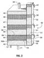
- FIG. 1this shows schematically a three compartment unit together with a pre-treatment unit.
- the treatment system 1comprises a set of boxes 2, 3, 4, 5, 6, 7 and 8. These can be fabricated as separate units, or they can be fabricated in pairs as shown, or as a single complete treatment system.
- a flow of incoming aqueous emulsion 9enters box 2, which is a pretreatment unit.
- the emulsion flow 9will enter this box typically at about one third to one half way up from the bottom. In this box, any large droplets coalesce into a separated non-aqueous phase 10, which is removed through the pipe 11.
- the next box 3has foraminous sidewalls 12 and 13, and a solid top sheet 14.
- the boxis packed with high surface area polymeric material 15, which is a particulate foam.
- the foamis used in a particulate form, in part to assist in packing the box, and in part to ensure the exposure of a high surface area to the flow through the box.
- a typical particle sizeis from about 5mm to about 20mm.
- the separated aqueous emulsion phase 16 from box 2enters box 3 through the wall 12, contacts the polymeric material 15, and passes through wall 13 into box 4.
- box 3further separation of the non-aqueous and aqueous phases occurs.
- box 4the two phases separate to provide a second separated non-aqueous phase 17 which is recovered through the pipe 18, and a treated aqueous phase 19 passes to box 5.
- box 4includes an enlarged optional catchment space extending over the top of box 3.
- Boxes 5 and 6are constructed in the same way as boxes 3 and 4.
- Treated aqueous phase 19enters box 5 through the foraminous wall 20, contacts the polymeric material 21, and leaves through foraminous wall 22.
- box 6further non-aqueous phase 23 separates, is collected, and recovered through the pipe 24.
- Twice treated aqueous phase 25passes to boxes 7 and 8, which again are the same as boxes 3 and 4, with a third body of polymeric material between two foraminous walls.
- box 8further non-aqueous phase 26 is collected and recovered through pipe 27, and a flow 28 of treated aqueous phase leaves the system from box 8.
- a suitable flow control deviceis used, such as a float operated automatic valve, or a time sequenced valve.
- the flow rate of incoming aqueous emulsion 9is adjusted so that there is an adequate contact time between the aqueous emulsion and the polymeric material in boxes 3, 5 and 7 to effect separation of the non-aqueous phase, and to form a free floating non-aqueous phase layer. In practise, this is generally found to be sufficient to provide droplets having a size in excess of at least about 150 ⁇ m.
- the third body of polymeric material in box 7should be Kozlowski polyurethane foam.
- the Kozlowski polyurethane foamwill be acting as an absorbent only, and not as an emulsion breaker. Consequently, when the third body - or the last if more than three are used - is a Kozlowski polyurethane foam functioning as only an absorbent, a separate non-aqueous phase will not be formed, and there will not be a non-aqueous phase flow in pipe 27.
- the treated aqueous phasehas to be monitored, so that when the Kozlowski polyurethane foam becomes fully loaded with non-aqueous phase (which will be indicated by a rise in concentration in the treated flow 28) it is removed, and the non-aqueous phase recovered from it, typically by centrifugation.
- the Kozlowski polyurethane foambecomes fully loaded with non-aqueous phase (which will be indicated by a rise in concentration in the treated flow 28) it is removed, and the non-aqueous phase recovered from it, typically by centrifugation.
- the incoming aqueous flow 9is heavily contaminated with the non-aqueous phase, more than three polymeric material bodies may be required. The number required will be largely determined by the level of contamination which is acceptable in the effluent water from the treatment unit. If the incoming aqueous flow also contains solid material, it is advantageous to provide a vent 29 from box 2 so that accumulated solids can be periodically removed.
- the polymeric material in the first compartmentmay also need to be inspected periodically, and replaced if it becomes clogged with suspended small particle size solids in the aqueous flow which have not been separated in a pretreatment stage.
- This unithas the advantage that the non-aqueous phase droplets as they are detached from the body of polymeric material simply continue to rise away from it, and it is only the treated flow which moves laterally.
- FIG 1the flow of aqueous emulsion through the bodied of polyurethane material in treatment stages is essentially horizontal. It is also possible to arrange the treatment stages so that the flow passes through the polyurethane body essentially vertically, in either an upward or a downward direction.
- a suitable treatment unitis shown in Figure 2 in which the flow passes in an upward direction.
- the treatment unit 40 as shownis essentially a single structure: like the horizontal unit it can be made as one integral structure or from several separate interconnected boxes.
- Aqueous emulsionenters the bottom of the unit through a pipe as at 41 into the first box 43.
- a drain 42can be provided to deal with any solids that accumulate in box 43.
- the boxesthen alternate upwardly: boxes 43, 45, 47 and 49 contain the aqueous phase flowing through the treatment unit, and boxes 44, 46 and 48 contain the high surface area polymeric material.
- Catchment boxes 50, 51, 52 and 53are then located beside each pair of boxes.
- the construction and operation of boxes 43, 44 and 50is exemplary.
- the polymeric materialis located on a grid 54, such as a perforated metal plate, and between the outer solid wall 56A and inner wall 56B.
- the wall 56Bincludes a row of perforations or slots across the box 43 just below the grid 54.
- the top surface 57 of the catchment box 57is solid.
- a second perforated metal plate 55can be located above the body of polymeric material 58.
- the separated oil dropletstend to collect on its lower surface, and tend not to percolate through it; the separated oil droplets travel sideways through the perforations or slots in wall 56B into the catchment box 50.
- Separated oilcollects as a second phase as at 59, and is removed through the pipe 60.
- Flow through the pipe 60is again controlled in any suitable way, for example a float controlled automatic valve or a time sequenced valve.
- the two following unitsoperate in the same way, to provide a treated water flow into the following box above, and an oil flow in the pipes 61 and 62.
- the last box 49, together with its catchment box 53, operatedepends on the amount of oil still in the aqueous emulsion flow reaching it, and the amount of oil that can be accepted in the effluent treated water flow 64.
- a suitable wire arrangementis provided between the box 49 and the catchment box 53. If the last body of polymeric material in box 48 is Kozlowski polyurethane foam that is functioning only as an absorbent, then there should be no separated oil flow into the catchment box 53, and hence no oil flow in the pipe 63. In the alternative, if the last body of polymeric material in box 48 is functioning to separate further oil, then it is possible that there can be some oil droplets in the water in box 49. These are then trapped in the catchment box 53, and recovered as an oil phase through pipe 63.
- the treatment unit in Figure 2includes three polyurethane bodies. How many bodies are used will be determined by essentially three factors: the quantity of emulsion to be treated, the amount of non-aqueous material in the emulsion, and the quality level required in the outflow of treated water. It is therefore possible the more than the three units shown will be required in some cases. Since units of this type are often required to be used either under adverse conditions, or under conditions where only minimal supervision is possible, it is preferred that the number of treatment units used should be more than analyses indicate to be required, thus providing a safety margin.
- FIG. 3shows comparative performance data for five different polyurethane materials. This data is based on a single pass test, in which an aqueous oil emulsion was passed through a body of each foam material, and the oil content at both inlet and outlet was determined. In these tests, a 10 cm diameter pipe was used containing five compartments. The first and third compartments, each about 4 cm in length, contained the test sample of polyurethane.
- the first, third and fifth compartmentwere empty, and about 0.8 cm in length.
- the flow through the test pipewas horizontal.
- the emulsion usedwas 10W30 motor oil mixed into water using a centrifugal pump at 3,450 rpm.
- the flow ratewas constant, at 1.5 L/min.
- the five polyurethane materialsare identified as follows.
- Product Bis a standard commercial product available from many sources; its composition is not known. The product was supplied by Eversoft Fibre and Foam Ltd. Products C, D and E are all commercially available, and are made by Flexible Products Co., Joliet, Illinois, USA. The main components appear to be 4,4'-diphenylmethanediisocyante, a polyether/polyol blend, and a blowing agent. As Figure 3 shows, all of these products are capable of significantly reducing the oil content of the oil and water system tested.
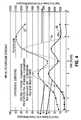
- FIGS. 4 , 5 , 6 and 7the results of similar test are shown using other polymeric materials, with a polyurethane foam included for comparison.
- the cylindercontained four compartments packed with the polymeric material, the flow rate was 1.2 litres/minute, and the test oil in the emulsion was 10W30 motor oil.
- the test polymers usedwere:
- polyester and polyurethanewere used as foams; the polyethylene, polystyrene and polypropylene were used as high surface area small particles, which were thin cutting chips (similar to swarf) with a maximum dimension of about 5mm.
- the mixture of oil and waterwas passed through the cylinder, and the oil level measured before and after treatment. The oil level in the aqueous flow was not constant.
- the horizontal axisis time in hours; and the vertical axes are in parts per million (ppm).
- the left axisrefers to the treated aqueous flow, and the right axis to the untreated aqueous flow; these axes are not to the same scale.
- trace Ais the incoming aqueous oil containing flow; trace B is after treatment with polyurethane, and trace C is after treatment with the test polymer.
- trace Cis after treatment with the test polymer.
- the tracesshow that the amount of oil left in the aqueous flow is related to the amount of oil present initially. These traces also show that of the materials tested, the polyurethane appears to be the most effective, and reduces the oil level to generally less than a maximum of about 50ppm.
Landscapes
- Chemical & Material Sciences (AREA)
- Chemical Kinetics & Catalysis (AREA)
- Thermal Sciences (AREA)
- Physics & Mathematics (AREA)
- Analytical Chemistry (AREA)
- Separation, Recovery Or Treatment Of Waste Materials Containing Plastics (AREA)
- Water Treatment By Sorption (AREA)
- Manufacture Of Porous Articles, And Recovery And Treatment Of Waste Products (AREA)
- Solid-Sorbent Or Filter-Aiding Compositions (AREA)
- Physical Water Treatments (AREA)
- Removal Of Floating Material (AREA)
- Processing And Handling Of Plastics And Other Materials For Molding In General (AREA)
- Materials For Medical Uses (AREA)
- Dental Preparations (AREA)
- Colloid Chemistry (AREA)
- Polyurethanes Or Polyureas (AREA)
Abstract
Description
- In the recent past, there have been several well documented instances of the inadvertent spillage of liquids causing both environmental, ecological, and even toxicological problems for plant species, insects, wild life; and even people. Examples of spilled liquids include oils and solvents, and a group of materials known loosely as PCB's. For many of these liquids, methods of clean up are known, even for relatively difficult ones, such as crude oil and PCB's.
- For many of these materials, a feasible method of both clean up and recovery is described by
Kozlowski, in US 5,239,040 . This method has been shown to be both practical, and effective, in that rather than simply dispersing the spilled liquid with, for example, a detergent, the spilled liquid itself is recovered. It is then possible to separate the recovered liquid from the recovery agent so that the recovered liquid can be safely dealt with in an appropriate fashion, and so that the recovery agent itself an be re-used to capture more liquid. As described by Kozlowski, the recovery agent and the recovered liquid are separated by centrifugation. The recovery agent described Kozlowski is a polyurethane foam material, which is prepared from specified reactants using a particular process. Hereafter this material will be described as "Kozlowski polyurethane foam". - In addition to its ability to function as a re-useable liquid recovery agent, Kozlowski polyurethane has been shown to be useable to recover, for example, oil which has been spilled onto water. The Kozlowski polyurethane has been shown to be able to absorb, for example, oil not only when the foam is essentially dry but also when the foam is essentially fully wet or even waterlogged.
- Another difficulty with spilt non-aqueous liquids arises when water is present. A water immiscible liquid can be present in association with water in two quite different forms. At least a part of it will generally be present as a discrete second phase, which may be heavier or lighter than water. The remainder will generally be present as an emulsion, of at least some level of stability, and in which water can be either the continuous phase or the disperse phase. In both cases; there is also the difficulty that nearly all substances that appear to be immiscible with water, for example light hydrocarbons such as benzene, in fact are soluble in water to a small extent, often at a level of parts per million. For an aqueous emulsion in which water is the continuous phase,
Kozlowski, in WO 94/21347 - In
WO 94/21347 Kozlowski - Although the procedure described by
Kozlowski in WO 94/21347 WO 94/21347 - The only other apparently viable alternative for dealing with emulsions is to flocculate the droplets until a size is reached at which separation into two phases will occur. This will generally require flocculation to a droplet size in excess of at least 30µm. However, this technique requires the consumption of chemicals and the creation of a chemical sludge. It is consequently not environmentally friendly in use.
- This invention seeks to overcome these difficulties, and to provide a treatment apparatus and process which will deal with aqueous emulsions reasonably quickly, and which will provide the non-aqueous phase in a recoverable form.
- This invention is based on the discovery that not only Kozlowski polyurethane foam, but also other polymeric materials when fabricated into a body of high surface area material such as a foam, if used under the correct conditions, will function as an emulsion breaker, and will separate a flow of an aqueous emulsion into two separate phases. It has now been found that when several polymeric materials when fabricated into a body of high surface area material are exposed, for example, to a flow of an emulsion of oil and water containing up to at least about 10,000 ppm dispersed oil, two processes appear to take place. First, the polymeric material absorbs oil until it becomes saturated with oil. Second, as the polymeric material continues to absorb more oil, it releases as much oil as it absorbs, but it does so at a droplet size which is sufficiently large to coalesce into a separate oil phase. It is then possible to separate the aqueous and non-aqueous phases, and recover each of the two phases separately. Further, by the use of a sequence of treatment steps, the majority of the emulsified non-aqueous material can be recovered, so that a Kozlowski polyurethane foam absorbent only may be necessary for the last, or for the last few, treatment steps in the sequence. The only significant restrictions on the polymer material appear to be first the ability to form a high surface area material, such as a foam, from it, and second that the polymeric material chosen is resistant to degradation under the conditions of use; for example, a polyester material is not suitable under alkaline conditions which will result in hydrolytic degradation of the polymer, but which would be resisted by a polyalkylene such as polyethylene.
US 4213863 describes a flow-through coalescing separator.- Thus in its broadest embodiment, this invention seeks to provide a continuous process for separating a flow of an aqueous emulsion, including an aqueous continuous phase and a non-aqueous disperse phase, to provide a first flow comprising a recovered non-aqueous phase, and to provide a second flow comprising a recovered aqueous phase containing an acceptable level of the non-aqueous phase, which continuous process comprises:
- (a) passing a flow of aqueous emulsion through a fixed, upstream foraminous sidewall of a first enclosure having an opposed, fixed, downstream foraminous sidewall for contacting the flow of aqueous emulsion with a first body of a particulate polymeric foam material having a high surface area packed in said enclosure;
- (b) allowing the first body of the particulate polymeric foam material to become saturated with the non-aqueous phase of the flow of the emulsion;
- (c) continuing the flow of aqueous emulsion until a separate non-aqueous phase and a treated aqueous phase is formed;
- (d) separating the separated non-aqueous phase obtained in step (c) from the treated aqueous phase after the flow passes through the fixed downstream foraminous sidewall without stopping the flow of aqueous emulsion through the fixed upstream foraminous sidewall;
- (e) recovering the separated non-aqueous phase obtained in step (d) without stopping the flow of aqueous emulsion through the fixed upstream foraminous sidewall;
- (f) recovering a flow of treated aqueous phase without stopping the flow of aqueous emulsion through the fixed upstream foraminous sidewall; and
- (g) if required, repeating steps (a) to (f) with at least one other enclosure having a fixed, upstream foraminous sidewall and an opposed, fixed downstream foraminous sidewall to contact the flow of treated aqueous phase with at least one other body of a particulate polymeric foam material having a high surface area packed in said at least one other enclosure, until the acceptable level of non-aqueous phase is reached in the flow of aqueous phase.
- Preferably, the polymer used in the polymeric material is chosen from the group consisting of polyurethane, polypropylene, polystyrene, polyester, and polyethylene. More preferably, the polymeric material is polyurethane.
- The polymer material having a high surface area is a particulate polymeric foam material.
- Preferably, the flow of aqueous emulsion in step (a) contacts the first body of a particulate polymeric material in a flow direction chosen from the group consisting of horizontal, vertical downwardly, and vertical upwardly.
- Preferably, a plurality of bodies of particulate polymeric material is used, the flow contacts each of them in sequence, and separated non-aqueous phase is recovered from the flow after the each body of particulate polymeric material. Alternatively, a plurality of bodies of particulate polymeric material is used, the flow contacts each of them in sequence, and separated non-aqueous phase is recovered from the flow after each body of particulate polymeric material except for the last, and separated non-aqueous phase is recovered from the last body.
- Preferably, when a sequence of bodies of particulate polymeric materials is used, at least the last body of particulate polymeric material comprises a Kozlowski polyurethane foam.
- Preferably, the process further includes pretreatment steps prior to step (a) in which steps:
- (h) non-aqueous phase droplets large enough to coalesce are allowed to form a separated non-aqueous phase,
- (i) the separated non-aqueous phase is recovered, and
- (j) the aqueous phase is recovered and used as the flow in step (a).
- The invention will now be described by way of reference to the attached drawings in which:
Figure 1 shows schematically a three unit treatment system;Figure 2 shows schematically an alternative unit;Figure 3 shows graphically the performance of Kozlowski polyurethane and four other commercially available polyurethane materials;Figures 4 ,5 ,6 and7 show graphically the performance of foams of polyurethane, polypropylene, polystyrene, polyester, and polyethylene.- Referring first to
Figure 1 , this shows schematically a three compartment unit together with a pre-treatment unit. The treatment system 1 comprises a set ofboxes aqueous emulsion 9 entersbox 2, which is a pretreatment unit. Theemulsion flow 9 will enter this box typically at about one third to one half way up from the bottom. In this box, any large droplets coalesce into a separatednon-aqueous phase 10, which is removed through thepipe 11. - The
next box 3 hasforaminous sidewalls top sheet 14. The box is packed with high surfacearea polymeric material 15, which is a particulate foam. The foam is used in a particulate form, in part to assist in packing the box, and in part to ensure the exposure of a high surface area to the flow through the box. A typical particle size is from about 5mm to about 20mm. The separatedaqueous emulsion phase 16 frombox 2 entersbox 3 through thewall 12, contacts thepolymeric material 15, and passes throughwall 13 intobox 4. Inbox 3, further separation of the non-aqueous and aqueous phases occurs. Inbox 4, the two phases separate to provide a second separatednon-aqueous phase 17 which is recovered through thepipe 18, and a treatedaqueous phase 19 passes tobox 5. As shown,box 4 includes an enlarged optional catchment space extending over the top ofbox 3. Boxes boxes aqueous phase 19 entersbox 5 through theforaminous wall 20, contacts thepolymeric material 21, and leaves throughforaminous wall 22. Inbox 6further non-aqueous phase 23 separates, is collected, and recovered through thepipe 24. Twice treatedaqueous phase 25 passes toboxes boxes box 8further non-aqueous phase 26 is collected and recovered throughpipe 27, and aflow 28 of treated aqueous phase leaves the system frombox 8. In each ofpipes - In the treatment system, the flow rate of incoming
aqueous emulsion 9 is adjusted so that there is an adequate contact time between the aqueous emulsion and the polymeric material inboxes - If the acceptable level of non-aqueous phase in the treated
aqueous phase 28 is extremely low, for example if the treated aqueous phase is intended to meet the standards for potable water, then it is recommended that at least the third body of polymeric material inbox 7 should be Kozlowski polyurethane foam. In that case, the Kozlowski polyurethane foam will be acting as an absorbent only, and not as an emulsion breaker. Consequently, when the third body - or the last if more than three are used - is a Kozlowski polyurethane foam functioning as only an absorbent, a separate non-aqueous phase will not be formed, and there will not be a non-aqueous phase flow inpipe 27. Instead, the treated aqueous phase has to be monitored, so that when the Kozlowski polyurethane foam becomes fully loaded with non-aqueous phase (which will be indicated by a rise in concentration in the treated flow 28) it is removed, and the non-aqueous phase recovered from it, typically by centrifugation. In order to avoid having to cease processing while non-aqueous phase is recovered from the loaded Kozlowski polyurethane, it is convenient to provide two treatment units in parallel, which are used alternately. - Similarly, if the incoming
aqueous flow 9 is heavily contaminated with the non-aqueous phase, more than three polymeric material bodies may be required. The number required will be largely determined by the level of contamination which is acceptable in the effluent water from the treatment unit. If the incoming aqueous flow also contains solid material, it is advantageous to provide avent 29 frombox 2 so that accumulated solids can be periodically removed. - The polymeric material in the first compartment may also need to be inspected periodically, and replaced if it becomes clogged with suspended small particle size solids in the aqueous flow which have not been separated in a pretreatment stage.
- This unit has the advantage that the non-aqueous phase droplets as they are detached from the body of polymeric material simply continue to rise away from it, and it is only the treated flow which moves laterally.
- In
Figure 1 the flow of aqueous emulsion through the bodied of polyurethane material in treatment stages is essentially horizontal. It is also possible to arrange the treatment stages so that the flow passes through the polyurethane body essentially vertically, in either an upward or a downward direction. A suitable treatment unit is shown inFigure 2 in which the flow passes in an upward direction. - In
Figure 2 thetreatment unit 40 as shown is essentially a single structure: like the horizontal unit it can be made as one integral structure or from several separate interconnected boxes. Aqueous emulsion enters the bottom of the unit through a pipe as at 41 into thefirst box 43. If desired, adrain 42 can be provided to deal with any solids that accumulate inbox 43. The boxes then alternate upwardly:boxes boxes Catchment boxes boxes grid 54, such as a perforated metal plate, and between the outersolid wall 56A andinner wall 56B. Thewall 56B includes a row of perforations or slots across thebox 43 just below thegrid 54. Thetop surface 57 of thecatchment box 57 is solid. As the emulsion encounters the saturated body ofpolymeric material body 58, the aqueous phase continues more or less upwardly through it, and into the next box. If desired, a secondperforated metal plate 55 can be located above the body ofpolymeric material 58. As the polymeric material breaks the emulsion, the separated oil droplets tend to collect on its lower surface, and tend not to percolate through it; the separated oil droplets travel sideways through the perforations or slots inwall 56B into thecatchment box 50. Separated oil collects as a second phase as at 59, and is removed through thepipe 60. Flow through thepipe 60 is again controlled in any suitable way, for example a float controlled automatic valve or a time sequenced valve. The two following units operate in the same way, to provide a treated water flow into the following box above, and an oil flow in thepipes - How the
last box 49, together with itscatchment box 53, operate depends on the amount of oil still in the aqueous emulsion flow reaching it, and the amount of oil that can be accepted in the effluent treatedwater flow 64. In order to separate any free oil in the incoming water a suitable wire arrangement is provided between thebox 49 and thecatchment box 53. If the last body of polymeric material inbox 48 is Kozlowski polyurethane foam that is functioning only as an absorbent, then there should be no separated oil flow into thecatchment box 53, and hence no oil flow in thepipe 63. In the alternative, if the last body of polymeric material inbox 48 is functioning to separate further oil, then it is possible that there can be some oil droplets in the water inbox 49. These are then trapped in thecatchment box 53, and recovered as an oil phase throughpipe 63. - As described, the treatment unit in
Figure 2 includes three polyurethane bodies. How many bodies are used will be determined by essentially three factors: the quantity of emulsion to be treated, the amount of non-aqueous material in the emulsion, and the quality level required in the outflow of treated water. It is therefore possible the more than the three units shown will be required in some cases. Since units of this type are often required to be used either under adverse conditions, or under conditions where only minimal supervision is possible, it is preferred that the number of treatment units used should be more than analyses indicate to be required, thus providing a safety margin. - In the practise of this invention, as noted above, if a very low level of non-aqueous material in the aqueous phase is required it is usually desirable to use a Kozlowski polyurethane in at least the last treatment stage. For the earlier stage, or stages, other particulate polymeric foam materials can be used.
Figure 3 shows comparative performance data for five different polyurethane materials. This data is based on a single pass test, in which an aqueous oil emulsion was passed through a body of each foam material, and the oil content at both inlet and outlet was determined. In these tests, a 10 cm diameter pipe was used containing five compartments. The first and third compartments, each about 4 cm in length, contained the test sample of polyurethane. The first, third and fifth compartment were empty, and about 0.8 cm in length. The flow through the test pipe was horizontal. The emulsion used was 10W30 motor oil mixed into water using a centrifugal pump at 3,450 rpm. The flow rate was constant, at 1.5 L/min. - In
Figure 3 , the effluent oil level(vertical axis) is plotted against the inlet oil level(horizontal axis), in ppm on both axes. - The five polyurethane materials are identified as follows.
- A: Kozlowski polyurethane foam.
- B: Upholstery grade foam chips, composition unknown.
- C: Great Stuff(TM) polyurethane foam.
- D: Great Stuff (TM) expanding polyurethane foam.
- E: All Direction Great Stuff(TM) polyurethane foam.
- Product B is a standard commercial product available from many sources; its composition is not known. The product was supplied by Eversoft Fibre and Foam Ltd. Products C, D and E are all commercially available, and are made by Flexible Products Co., Joliet, Illinois, USA. The main components appear to be 4,4'-diphenylmethanediisocyante, a polyether/polyol blend, and a blowing agent. As
Figure 3 shows, all of these products are capable of significantly reducing the oil content of the oil and water system tested. Figures 4 ,5 ,6 and7 the results of similar test are shown using other polymeric materials, with a polyurethane foam included for comparison. In these tests, the cylinder contained four compartments packed with the polymeric material, the flow rate was 1.2 litres/minute, and the test oil in the emulsion was 10W30 motor oil. The test polymers used were:- in
Figure 4 , polyethylene; - in
Figure 5 , polyester; - in
Figure 6 , polystyrene; and - in
Figure 7 , polypropylene. - The polyester and polyurethane were used as foams; the polyethylene, polystyrene and polypropylene were used as high surface area small particles, which were thin cutting chips (similar to swarf) with a maximum dimension of about 5mm. In each experiment, the mixture of oil and water was passed through the cylinder, and the oil level measured before and after treatment. The oil level in the aqueous flow was not constant.
- In each of
Figures 4 - 7 the horizontal axis is time in hours; and the vertical axes are in parts per million (ppm). The left axis refers to the treated aqueous flow, and the right axis to the untreated aqueous flow; these axes are not to the same scale. In each Figure, trace A is the incoming aqueous oil containing flow; trace B is after treatment with polyurethane, and trace C is after treatment with the test polymer. In each Figure the traces show that the amount of oil left in the aqueous flow is related to the amount of oil present initially. These traces also show that of the materials tested, the polyurethane appears to be the most effective, and reduces the oil level to generally less than a maximum of about 50ppm.
Claims (16)
- A continuous process for separating a flow of an aqueous emulsion, including an aqueous continuous phase and a non-aqueous disperse phase, to provide a first flow comprising a recovered non-aqueous phase, and to provide a second flow comprising a recovered aqueous phase containing an acceptable level of the non-aqueous phase, which continuous process comprises:(a) passing a flow of aqueous emulsion through a fixed, upstream foraminous sidewall of a first enclosure having an opposed, fixed, downstream foraminous sidewall for contacting the flow of aqueous emulsion with a first body of a particulate polymeric foam material having a high surface area packed in said enclosure;(b) allowing the first body of the particulate polymeric foam material to become saturated with the non-aqueous phase of the flow of the emulsion;(c) continuing the flow of aqueous emulsion until a separate non-aqueous phase and a treated aqueous phase is formed;(d) separating the separated non-aqueous phase obtained in step (c) from the treated aqueous phase after the flow passes through the fixed downstream foraminous sidewall without stopping the flow of aqueous emulsion through the fixed upstream foraminous sidewall;(e) recovering the separated non-aqueous phase obtained in step (d) without stopping the flow of aqueous emulsion through the fixed upstream foraminous sidewall;(f) recovering a flow of treated aqueous phase without stopping the flow of aqueous emulsion through the fixed upstream foraminous sidewall; and(g) if required, repeating steps (a) to (f) with at least one other enclosure having a fixed, upstream foraminous sidewall and an opposed, fixed downstream foraminous sidewall to contact the flow of treated aqueous phase with at least one other body of a particulate polymeric foam material having a high surface area packed in said at least one other enclosure, until the acceptable level of non-aqueous phase is reached in the flow of aqueous phase.
- A process according to Claim 1 wherein the polymer in the particulate polymeric foam material is chosen from the group consisting of polyurethane, polypropylene, polystyrene, polyester, and polyethylene.
- A process according to Claim 2 wherein the polymer in the particulate polymeric foam material is polyurethane.
- A process according to any one of claims 1 to 3 wherein a plurality of bodies of particulate polymeric foam material is used, the flow contacts each of them in sequence, and separated non-aqueous phase is recovered after each body of particulate polymeric foam material.
- A process according to any one of claims 1 to 3 wherein a plurality of bodies of particulate polymeric foam material is used, the flow contacts each of them in sequence, separated non-aqueous phase is recovered after each body of particulate polymeric foam material except the last, and separated aqueous phase is recovered from the last body.
- A process according to any one of claims 1 to 5 wherein, when a sequence of bodies of particulate polymeric foam materials is used, at least the last body of particulate polymeric foam material comprises a Koziowski polyurethane.
- A process according to any of claims 1 to 6 which further includes pretreatment steps in which steps:- non-aqueous phase droplets large enough to coalesce are allowed to form a separated non-aqueous phase,- the separated non-aqueous phase is recovered, and- the aqueous phase is recovered and used as the flow to the first enclosure.
- An apparatus for carrying out a process according to any one of claims 1 to 7, which apparatus comprises in combination at least a first compartment and a second compartment wherein:(a) the first compartment includes- a first feed means for receiving the flow of emulsion into a first box occupying part of the space within the first compartment, which first box is packed with a first body of high surface area particulate polymeric foam material, said first feed means comprising a fixed upstream foraminous sidewall (12) of said first box;- an opposed fixed downstream foraminous sidewall (13) forming part of the first box through which separated emulsion flows into a first separation space comprising the remainder of the space within the first compartment;- a first non-aqueous phase recovery means constructed and arranged to recover separated non-aqueous phase from the first separation space; and- a first aqueous phase recovery means; and(b) the second compartment includes- a second feed means for receiving the flow of first aqueous phase into a second box occupying part of the space within the second compartment, which second box is packed with a second body of high surface area particulate polymeric foam material, said second feed means comprising a fixed upstream foraminous sidewall (20) of said second box;- an opposed fixed downstream foraminous sidewall (22) forming part of the second box through which separated emulsion flows into a separation space comprising the remainder of the space within the second compartment;- a second non-aqueous phase recovery means constructed and arranged to recover separated non-aqueous phase from the second separation space; and- a second aqueous phase recovery means.
- An apparatus according to Claim 8 further including between the first and second compartments at least one third compartment which together provide a continuous flow path, wherein the at least one third compartment includes:- a third feed means for receiving the flow of aqueous phase from an immediately adjacent compartment upstream in the flow path into a third box occupying part of the space within the third compartment, which third box is packed with a third body of high surface area particulate polymeric foam material, said third feed means comprising a fixed upstream foraminous sidewall of said third box;- an opposed fixed downstream foraminous sidewall forming part of the third box through which separated emulsion flows into a third separation space comprising the remainder of the space within the third compartment;- a third non-aqueous phase recovery means constructed and arranged to recover separated non-aqueous phase from the third separation space; and- a third aqueous phase recovery means constructed and arranged to deliver the third aqueous phase to an immediately adjacent compartment downstream in the flow path.
- An apparatus according to Claims 8 or 9 wherein, in each compartment other than the first compartment, the feed means for receiving the flow of aqueous phase comprises a common foraminous wall separating two compartments.
- An apparatus according to Claims 8, 9 or 10 wherein the aqueous phase flows through the compartments in an essentially horizontal direction.
- An apparatus according to Claims 8, 9 or 10 wherein the aqueous phase flows through the compartments in an essentially vertical direction.
- An apparatus according to any one of Claims 8 to 12 wherein in each box the high surface area particulate polymeric foam material is the same.
- An apparatus according to any one of Claims 8 to 12 wherein in each box the high surface area particulate polymeric foam material is not the same.
- An apparatus according to any one of Claims 8 to 14 wherein each high surface area particulate polymeric foam material is chosen from the group consisting of polyurethane, polypropylene, polystyrene, polyester, and polyethylene.
- An apparatus according to any one of Claims 8 to 15 which further includes a pretreatment unit having a feed means for receiving the flow of aqueous emulsion, a pretreatment box and a recovery means for transferring aqueous phase to the first feed means in the first compartment.
Applications Claiming Priority (3)
| Application Number | Priority Date | Filing Date | Title |
|---|---|---|---|
| GBGB0022013.7AGB0022013D0 (en) | 2000-09-07 | 2000-09-07 | Polyurethane oil de-emulsification unit |
| GB0022013 | 2000-09-07 | ||
| PCT/CA2001/001284WO2002020115A2 (en) | 2000-09-07 | 2001-09-07 | Polyurethane oil de-emulsification unit |
Publications (2)
| Publication Number | Publication Date |
|---|---|
| EP1322393A2 EP1322393A2 (en) | 2003-07-02 |
| EP1322393B1true EP1322393B1 (en) | 2008-02-13 |
Family
ID=9899062
Family Applications (1)
| Application Number | Title | Priority Date | Filing Date |
|---|---|---|---|
| EP01971552AExpired - LifetimeEP1322393B1 (en) | 2000-09-07 | 2001-09-07 | Polyurethane oil de-emulsification unit |
Country Status (16)
| Country | Link |
|---|---|
| US (4) | US7416667B2 (en) |
| EP (1) | EP1322393B1 (en) |
| JP (1) | JP3619824B2 (en) |
| KR (1) | KR100493812B1 (en) |
| CN (1) | CN1289166C (en) |
| AT (1) | ATE385846T1 (en) |
| AU (1) | AU2001291548A1 (en) |
| BR (1) | BR0113888A (en) |
| CA (1) | CA2421076C (en) |
| DE (1) | DE60132792D1 (en) |
| DZ (1) | DZ3436A1 (en) |
| GB (1) | GB0022013D0 (en) |
| MX (1) | MXPA03002001A (en) |
| NO (2) | NO329083B1 (en) |
| RU (1) | RU2288770C2 (en) |
| WO (1) | WO2002020115A2 (en) |
Families Citing this family (23)
| Publication number | Priority date | Publication date | Assignee | Title |
|---|---|---|---|---|
| GB0022013D0 (en)* | 2000-09-07 | 2000-10-25 | Earth Canada Corp | Polyurethane oil de-emulsification unit |
| MXPA05010601A (en)* | 2003-04-01 | 2006-03-09 | Separatech Canada Inc | Method and apparatus for oil water separation. |
| CA2511884C (en)* | 2004-01-15 | 2010-11-16 | Environmental Applied Research Technology House - Earth (Canada) Corpora Tion; Maison De Recherche Appliquee Et De Technologie En Matiere Environ | Reusable sorbing coalescing agent |
| EP1559465B1 (en)* | 2004-01-27 | 2019-03-27 | Services Petroliers Schlumberger | Small droplets recovery system |
| US7297279B2 (en)* | 2005-01-21 | 2007-11-20 | Amcol International Corporation | Method for removing oil from water coalescing in a polymer particle/fiber media |
| US20070221586A1 (en)* | 2005-06-27 | 2007-09-27 | Ruprecht John C | High pressure oil removing filter |
| US20080041796A1 (en)* | 2005-06-27 | 2008-02-21 | Ruprecht John C | High back pressure filter for removing non-water component(s) from water |
| US8334034B2 (en)* | 2006-09-27 | 2012-12-18 | Filtrona Porous Technologies Corp. | Rapid release and anti-drip porous reservoirs |
| CA2592190A1 (en) | 2007-06-18 | 2008-12-18 | Torr Canada Inc. | Coalescing agent |
| FR2957616B1 (en)* | 2010-03-22 | 2021-06-18 | F2F | RUNOFF WATER TREATMENT TANK |
| RU2467954C1 (en)* | 2011-06-17 | 2012-11-27 | Общество с ограниченной ответственностью "ИнтерФтор" | Method of cleaning surfaces of oil and liquid oil products |
| CN203281077U (en)* | 2013-05-27 | 2013-11-13 | 北京华阳利民仪器有限公司 | Demulsification column and an on-line automatic demulsification device in the extraction using the demulsification column |
| EP3122434A4 (en)* | 2014-03-27 | 2018-01-03 | Asama Coldwater Manufacturing Inc. | Filtration system |
| US20150299583A1 (en)* | 2014-04-21 | 2015-10-22 | Pentair Filtration Solutions, Llc | Separation system and method |
| CN103964545B (en)* | 2014-05-19 | 2015-05-06 | 华东理工大学 | Method and device for deep oil removal of wastewater containing low-concentration sump oil |
| US10035174B2 (en) | 2015-02-09 | 2018-07-31 | United Technologies Corporation | Open-cell reticulated foam |
| US10603610B2 (en) | 2016-08-17 | 2020-03-31 | Ingersoll-Rand Industrial U.S., Inc. | Oil water separator diffuser cap extension to filter cartridge |
| US10618821B2 (en) | 2016-08-17 | 2020-04-14 | Ingersoll-Rand Company | Oil water separator filter cartridge to housing engagement |
| US10953352B2 (en) | 2017-05-19 | 2021-03-23 | Baleen Process Solutions | Fluid treatment system and method of use utilizing a membrane |
| US20190126169A1 (en)* | 2017-10-30 | 2019-05-02 | Red Deer Ironworks Inc. | Horizontal production separator with helical emulsion circulation coils |
| US10913667B2 (en)* | 2017-12-08 | 2021-02-09 | Westech Engineering, Inc. | Multi-media clarification systems and methods |
| US12140139B2 (en)* | 2020-09-30 | 2024-11-12 | Solidification Products International, Inc. | Gravity flow filtration of hydrocarbons from an oil-in-water emulsion |
| US11583788B1 (en)* | 2022-01-18 | 2023-02-21 | Theodore A. Kuepper | Lightweight fibrous media (LFM) filter |
Family Cites Families (104)
| Publication number | Priority date | Publication date | Assignee | Title |
|---|---|---|---|---|
| BE357804A (en)* | 1928-02-04 | 1900-01-01 | ||
| US2405838A (en)* | 1944-03-01 | 1946-08-13 | Lawson Archibald | Liquid separator apparatus |
| US2731150A (en)* | 1952-05-26 | 1956-01-17 | Warner Lewis Company | Horizontal filter apparatus |
| US2985589A (en)* | 1957-05-22 | 1961-05-23 | Universal Oil Prod Co | Continuous sorption process employing fixed bed of sorbent and moving inlets and outlets |
| BE578628A (en)* | 1958-05-14 | |||
| US3106345A (en)* | 1961-06-14 | 1963-10-08 | Wukowitz Edward | Shower bath water control with additive attachment |
| US3231091A (en)* | 1962-10-29 | 1966-01-25 | Pfaudler Permutit Inc | Separator |
| US3503514A (en) | 1966-03-31 | 1970-03-31 | Archibald Lawson | Apparatus for separating mixed liquids |
| CH450364A (en)* | 1966-09-26 | 1968-01-31 | Hectronic Ag | Device for separating liquid petroleum products from a petroleum product-water mixture |
| US3946039A (en)* | 1967-10-30 | 1976-03-23 | Energy Research & Generation, Inc. | Reticulated foam structure |
| US3583904A (en) | 1969-01-22 | 1971-06-08 | Standard Oil Co Indiana | Method and apparatus for separating water from hydrocarbons |
| GB1298667A (en)* | 1969-02-24 | 1972-12-06 | Nat Res Dev | Improvements in the separation of liquids |
| US3645398A (en)* | 1969-07-24 | 1972-02-29 | Exxon Research Engineering Co | Coalescer cartridge and coalescer for oily water |
| US3779907A (en)* | 1970-04-13 | 1973-12-18 | Exxon Research Engineering Co | Liquid membrane process for the separation of aqueous mixtures |
| IL36739A0 (en)* | 1970-07-13 | 1971-06-23 | Hydronautics | Continuous fluid-solid contact method and apparatus |
| US3721069A (en)* | 1970-08-10 | 1973-03-20 | R Walker | Air-oil separator |
| US3797666A (en) | 1970-08-15 | 1974-03-19 | Toray Industries | Apparatus for separating fine oil droplets and sludge suspended in liquid |
| US3853753A (en)* | 1970-10-13 | 1974-12-10 | Amoco Prod Co | Removing oil from waste water with sulfur |
| US3800945A (en)* | 1971-11-26 | 1974-04-02 | Cata Sep Inc | Cell having catalytic action for coalescing oil droplets |
| US4039489A (en)* | 1972-02-22 | 1977-08-02 | Nasa | Oil and fat absorbing polymers |
| US3779908A (en)* | 1972-03-17 | 1973-12-18 | Continental Oil Co | Coalescence of water and oleophilic liquid dispersions by passage through a permeable, oleophilic liquid equilibrated, foam of polyurethane |
| US3738492A (en) | 1972-03-17 | 1973-06-12 | Brunswick Corp | Oil-water separator |
| BE794932A (en) | 1972-03-17 | 1973-05-29 | Continental Oil Co | PROCESS FOR CAUSING THE COALESCENCE OF DISPERSIONS OF WATER AND OLEOPHILIC LIQUIDS |
| AT313206B (en)* | 1972-03-20 | 1974-02-11 | Peter Jakubek Dipl Ing Dr Tech | Method for cleaning liquids contaminated with specifically lighter liquids and device for carrying out the method |
| US3862963A (en)* | 1972-04-26 | 1975-01-28 | Lion Fat Oil Co Ltd | Adsorbent for oils |
| BE795028A (en) | 1972-05-24 | 1973-05-29 | Continental Oil Co | PROCESS CAUSING THE COALESCENCE OF DISPERSIONS OF OLEOPHILIC LIQUIDS AND WATER |
| US3869408A (en) | 1972-07-13 | 1975-03-04 | Shell Oil Co | Method and apparatus for continuously separating emulsions |
| US3865732A (en)* | 1972-11-27 | 1975-02-11 | Fram Corp | Emulsion breaker |
| US3847821A (en) | 1973-10-19 | 1974-11-12 | Minnesota Mining & Mfg | Separator for removing a dispersed liquid phase from a continuous liquid phase |
| US3931019A (en)* | 1973-10-23 | 1976-01-06 | Products And Pollution Controls Co. | Reinforced coalescing cell |
| NL161365C (en)* | 1973-12-14 | 1980-02-15 | Geurtsen Deventer Maschf | DEVICE FOR SEPARATING A MIXTURE OF TWO NON-COMPLETELY MIXED LIQUIDS OF DIFFERENT SPECIAL WEIGHT, FOR EXAMPLE A MIX OF OIL AND WATER. |
| US3925202A (en)* | 1974-04-25 | 1975-12-09 | Hydromation Filter Co | Method of and apparatus for filtering water |
| US4022694A (en)* | 1974-05-06 | 1977-05-10 | Hydronautics, Incorporated | Oil-water separation apparatus |
| US4123365A (en)* | 1974-08-14 | 1978-10-31 | Ballast-Nedam Groep N.V. | Oil-water separator |
| GB1517715A (en) | 1974-11-26 | 1978-07-12 | British Petroleum Co | Apparatus for oil separation |
| US4199447A (en)* | 1975-03-13 | 1980-04-22 | Imperial Chemical Industries Limited | Coalescence of oil in oil/water emulsions |
| US4226722A (en)* | 1975-08-29 | 1980-10-07 | Amoco Production Company | Removing oil from waste water with sulfur |
| US4061573A (en)* | 1975-09-18 | 1977-12-06 | Seagull Industries, Inc. | Portable oil-water separation apparatus |
| DE2557327A1 (en)* | 1975-12-19 | 1977-06-30 | Metallgesellschaft Ag | METHOD AND DEVICE FOR INCREASING THE FLOW RATE OF TWO COUNTER-CURRENT LIQUIDS, NOT MIXABLE WITH EACH OTHER |
| US4196027A (en)* | 1976-03-26 | 1980-04-01 | Process Scientific Innovations Ltd. | Method of making filter elements for gas or liquid |
| JPS538872A (en)* | 1976-07-14 | 1978-01-26 | Oshima Katsutoshi | Method of separating foreign matters by using filter medium constituting float layer |
| JPS6048236B2 (en) | 1976-09-29 | 1985-10-25 | 東洋ゴム工業株式会社 | Polyurethane foam for wastewater and oil treatment containing surfactants |
| JPS5854604B2 (en) | 1977-02-08 | 1983-12-06 | 東洋ゴム工業株式会社 | How to purify oil emulsion wastewater |
| US4162973A (en)* | 1977-06-02 | 1979-07-31 | Afl Industries, Inc. | Water polishing system |
| US4308136A (en)* | 1978-04-21 | 1981-12-29 | Conoco Inc. | Internally baffled, horizontal flow, vertical oil skimmer |
| US4213863A (en)* | 1979-01-08 | 1980-07-22 | Marine Construction & Design Co. | Flow-through coalescing separator |
| US4220544A (en)* | 1979-05-21 | 1980-09-02 | Marine Construction & Design Co. | Apparatus for coalescing |
| EP0030569B1 (en)* | 1979-12-12 | 1984-03-14 | Girmes-Werke AG | Apparatus for the separation of oil from dispersions |
| CA1178542A (en)* | 1980-07-31 | 1984-11-27 | Utaro Sakai | Method and apparatus for oil-water separation by coalescence |
| JPS5738284A (en) | 1980-08-15 | 1982-03-02 | Hitachi Ltd | Oil pressure elevator device |
| US4356090A (en)* | 1981-09-28 | 1982-10-26 | Marine Construction & Design Co. | Flow-through oil/water separation filter |
| SU1242197A1 (en) | 1982-11-11 | 1986-07-07 | Предприятие П/Я М-5478 | Method of cleaning oil-bearing water |
| FR2552071B1 (en)* | 1983-09-21 | 1988-04-08 | Inst Nat Sciences Appliq | DEVICE FOR SEPARATING A PHASE DISPERSE IN EMULSION OR SUSPENSION IN A CONTINUOUS PHASE |
| DE3337655A1 (en) | 1983-10-17 | 1985-04-25 | Anlagen- Und Filterbau Gmbh & Co Kg, 6342 Haiger | Process and apparatus for purifying water polluted by hydrocarbons |
| DE3346931A1 (en) | 1983-12-24 | 1985-07-04 | Howaldtswerke - Deutsche Werft AG Hamburg und Kiel, 2300 Kiel | METHOD AND DEVICE FOR SEPARATING AN OIL-WATER MIXTURE |
| US4624765A (en)* | 1984-04-17 | 1986-11-25 | Exxon Research And Engineering Company | Separation of dispersed liquid phase from continuous fluid phase |
| DE3687419T2 (en)* | 1985-01-25 | 1993-05-19 | Asahi Chemical Ind | NON-WOVEN FABRIC, OIL-WATER SEPARATION FILTER AND OIL-WATER SEPARATION METHOD. |
| US4744889A (en)* | 1985-04-12 | 1988-05-17 | Jan Kruyer | Separation of viscous hydrocarbons and minerals particles from aqueous mixtures by mixtures by oleophilic adhesion |
| DE3618698A1 (en)* | 1986-06-04 | 1987-12-10 | Passavant Werke | METHOD FOR SEPARATING ORGANIC COMPOUNDS FROM WATER BY EXTRACTION |
| DE3706151A1 (en) | 1987-02-26 | 1988-09-08 | Bayer Ag | POLYHANE-MODIFIED POLYETHERURETHANES AND THEIR USE AS EMULSION SPLITTERS FOR WATER-IN-OIL EMULSIONS |
| US4929359A (en)* | 1988-01-26 | 1990-05-29 | The United States Of America As Represented By The United States Department Of Energy | Treatment of concentrated industrial wastewaters originating from oil shale and the like by electrolysis polyurethane foam interaction |
| US5004531A (en)* | 1988-01-26 | 1991-04-02 | Tiernan Joan E | Treatment of concentrated industrial wastewaters originating from oil shale and the like by electrolysis polyurethane foam interaction |
| US4844819A (en)* | 1988-06-03 | 1989-07-04 | Norman James M | Oil and water separator having plural nested tanks |
| US5023002A (en)* | 1990-04-09 | 1991-06-11 | Acs Industries, Inc. | Method and apparatus for recovering oil from an oil spill on the surface of a body of water |
| DE4040022A1 (en) | 1990-12-14 | 1992-06-17 | Bayer Ag | Splitting of water-in-oil emulsions |
| DE4200379A1 (en) | 1991-01-09 | 1992-07-16 | Domnick Hunter Filters Ltd | DEVICE FOR SEPARATING OIL FROM AN OIL / WATER MIXTURE |
| SG43896A1 (en) | 1991-05-07 | 1997-11-14 | Hoffmann La Roche | Cuvette for performing optical measurements |
| US5229015A (en)* | 1991-05-31 | 1993-07-20 | Nautus, Inc. | Liquid separator |
| US5229016A (en)* | 1991-08-08 | 1993-07-20 | Microfab Technologies, Inc. | Method and apparatus for dispensing spherical-shaped quantities of liquid solder |
| JP3106611B2 (en) | 1991-10-31 | 2000-11-06 | 松下電器産業株式会社 | Non-consumable electrode arc welding machine |
| US5194417A (en) | 1991-12-05 | 1993-03-16 | Quantum Chemical Corporation | Pretreatment of palladium-gold catalysts useful in vinyl acetate synthesis |
| US5239040A (en) | 1991-12-31 | 1993-08-24 | E.R.T. Environmental Research Technology K.S.P.W. Inc. | Liquid sorbent |
| US5331979A (en)* | 1992-07-27 | 1994-07-26 | Henley Julian L | Iontophoretic cigarette substitute |
| GB2276373A (en)* | 1993-03-22 | 1994-09-28 | Kspw Env Res Tech Inc | Water treatment process |
| GB2276331A (en) | 1993-03-22 | 1994-09-28 | Kspw Env Res Tech Inc | Flow through spill collection boom |
| US5531890A (en)* | 1993-05-28 | 1996-07-02 | Atlantic Richfield Company | Oil separation and disposal systems |
| CA2175088A1 (en) | 1993-10-25 | 1995-05-04 | Thomas Gradek | Boom system |
| CA2109467A1 (en) | 1993-10-28 | 1995-04-29 | Thomas Gradek | Sorbent for sorbing liquid |
| CA2122165A1 (en)* | 1994-04-26 | 1995-10-27 | Reginald Cormier | Domestic water recuperator for toilet use |
| US5549823A (en)* | 1994-06-28 | 1996-08-27 | Hirs; Gene | System for purifying a soluble oil emulsion |
| US5603825A (en)* | 1994-07-18 | 1997-02-18 | Costinel; Paul | Multi-stage apparatus for separating immiscible fluids |
| DE4434271C2 (en) | 1994-09-24 | 1996-11-28 | Buderus Guss Gmbh | Stackable coalescence element for insertion in a light liquid separator |
| JPH08252418A (en) | 1995-03-16 | 1996-10-01 | Kiichi Watanabe | Drain separation device |
| US5730872A (en)* | 1996-05-10 | 1998-03-24 | Rhodes; Laurence Mark | Apparatus for separating a mixture of liquids |
| US5762810A (en)* | 1996-11-22 | 1998-06-09 | Pelton; Paul | Coalescing oil/water separator |
| RU2104736C1 (en)* | 1996-12-04 | 1998-02-20 | Товарищество с ограниченной ответственностью "Фонд Прогресс" | Water purification device |
| DE19926313A1 (en)* | 1999-06-09 | 2000-12-14 | Satec Gmbh | Method and device for separating multiphase solvent mixtures with low density differences |
| US6422396B1 (en)* | 1999-09-16 | 2002-07-23 | Kaydon Custom Filtration Corporation | Coalescer for hydrocarbons containing surfactant |
| AU7436000A (en)* | 1999-09-22 | 2001-04-24 | Mantis Oil Separation Limited | Fluid control systems |
| GB0022013D0 (en)* | 2000-09-07 | 2000-10-25 | Earth Canada Corp | Polyurethane oil de-emulsification unit |
| US7341661B2 (en)* | 2000-11-16 | 2008-03-11 | Unit Process Technologies, L.L.C. | Clarification and sorptive-filtration system for the capture of constituents and particulate matter in liquids and gases |
| GB0217024D0 (en)* | 2002-07-23 | 2002-08-28 | Domnick Hunter Ltd | A coalescing filter element |
| US6907997B2 (en)* | 2003-02-19 | 2005-06-21 | Hancor, Inc. | Water clarification system with coalescing plates |
| MXPA05010601A (en)* | 2003-04-01 | 2006-03-09 | Separatech Canada Inc | Method and apparatus for oil water separation. |
| US7021471B2 (en)* | 2003-05-06 | 2006-04-04 | Hamilton Welding Company | Diffuser for an oil water separator system |
| WO2005014135A2 (en)* | 2003-08-12 | 2005-02-17 | Chemical Management Systems, Llc | Method and apparatus for purifying mixtures of oil and water |
| CA2511884C (en)* | 2004-01-15 | 2010-11-16 | Environmental Applied Research Technology House - Earth (Canada) Corpora Tion; Maison De Recherche Appliquee Et De Technologie En Matiere Environ | Reusable sorbing coalescing agent |
| EP1559465B1 (en)* | 2004-01-27 | 2019-03-27 | Services Petroliers Schlumberger | Small droplets recovery system |
| US7297279B2 (en)* | 2005-01-21 | 2007-11-20 | Amcol International Corporation | Method for removing oil from water coalescing in a polymer particle/fiber media |
| WO2008115788A2 (en)* | 2007-03-19 | 2008-09-25 | Pall Corporation | Fluid treatment elements and fluid treatment arrangements with posts and/or bands between fluid treatment elements and methods for making and using them |
| WO2008115791A2 (en)* | 2007-03-19 | 2008-09-25 | Pall Corporation | Fluid treatment arrangements with fluid treatment elements and methods for making and using them |
| EP2134453A1 (en)* | 2007-03-19 | 2009-12-23 | Pall Corporation | Fluid treatment elements and fluid treatment arrangements with spaces between fluid treatment elements and method for making and using them |
| CA2582585A1 (en)* | 2007-03-26 | 2008-09-26 | Separatech Canada Inc. | Cartridge separator for immiscible liquids |
| JP5123864B2 (en) | 2009-01-09 | 2013-01-23 | 本田技研工業株式会社 | Control device for belt type continuously variable transmission |
- 2000
- 2000-09-07GBGBGB0022013.7Apatent/GB0022013D0/ennot_activeCeased
- 2001
- 2001-09-07WOPCT/CA2001/001284patent/WO2002020115A2/enactiveIP Right Grant
- 2001-09-07RURU2003106707/15Apatent/RU2288770C2/ennot_activeIP Right Cessation
- 2001-09-07DEDE60132792Tpatent/DE60132792D1/ennot_activeExpired - Lifetime
- 2001-09-07CNCNB01815347XApatent/CN1289166C/ennot_activeExpired - Fee Related
- 2001-09-07USUS10/363,028patent/US7416667B2/ennot_activeExpired - Lifetime
- 2001-09-07AUAU2001291548Apatent/AU2001291548A1/ennot_activeAbandoned
- 2001-09-07MXMXPA03002001Apatent/MXPA03002001A/enactiveIP Right Grant
- 2001-09-07DZDZ013436Apatent/DZ3436A1/enactive
- 2001-09-07CACA002421076Apatent/CA2421076C/ennot_activeExpired - Lifetime
- 2001-09-07JPJP2002524596Apatent/JP3619824B2/ennot_activeExpired - Fee Related
- 2001-09-07BRBR0113888-0Apatent/BR0113888A/ennot_activeApplication Discontinuation
- 2001-09-07EPEP01971552Apatent/EP1322393B1/ennot_activeExpired - Lifetime
- 2001-09-07ATAT01971552Tpatent/ATE385846T1/ennot_activeIP Right Cessation
- 2001-09-07KRKR10-2003-7003250Apatent/KR100493812B1/ennot_activeExpired - Fee Related
- 2003
- 2003-03-06NONO20031041Apatent/NO329083B1/ennot_activeIP Right Cessation
- 2007
- 2007-12-21USUS12/003,333patent/US20080105619A1/ennot_activeAbandoned
- 2008
- 2008-05-27USUS12/153,879patent/US20090039021A1/ennot_activeAbandoned
- 2010
- 2010-06-24NONO20100914Apatent/NO337652B1/ennot_activeIP Right Cessation
- 2011
- 2011-04-05USUS13/080,475patent/US8721895B2/ennot_activeExpired - Fee Related
Also Published As
| Publication number | Publication date |
|---|---|
| KR100493812B1 (en) | 2005-06-08 |
| ATE385846T1 (en) | 2008-03-15 |
| JP3619824B2 (en) | 2005-02-16 |
| WO2002020115A2 (en) | 2002-03-14 |
| DE60132792D1 (en) | 2008-03-27 |
| WO2002020115A3 (en) | 2002-09-06 |
| RU2288770C2 (en) | 2006-12-10 |
| NO20100914L (en) | 2003-05-06 |
| JP2004507356A (en) | 2004-03-11 |
| CA2421076C (en) | 2006-02-14 |
| US20040112823A1 (en) | 2004-06-17 |
| US20080105619A1 (en) | 2008-05-08 |
| NO20031041L (en) | 2003-05-06 |
| US7416667B2 (en) | 2008-08-26 |
| BR0113888A (en) | 2004-06-08 |
| EP1322393A2 (en) | 2003-07-02 |
| CN1289166C (en) | 2006-12-13 |
| US20090039021A1 (en) | 2009-02-12 |
| US8721895B2 (en) | 2014-05-13 |
| GB0022013D0 (en) | 2000-10-25 |
| MXPA03002001A (en) | 2004-09-10 |
| CA2421076A1 (en) | 2002-03-14 |
| NO20031041D0 (en) | 2003-03-06 |
| NO337652B1 (en) | 2016-05-23 |
| AU2001291548A1 (en) | 2002-03-22 |
| CN1474711A (en) | 2004-02-11 |
| US20110226696A1 (en) | 2011-09-22 |
| KR20030059124A (en) | 2003-07-07 |
| DZ3436A1 (en) | 2002-03-14 |
| NO329083B1 (en) | 2010-08-16 |
Similar Documents
| Publication | Publication Date | Title |
|---|---|---|
| US8721895B2 (en) | Polyurethane oil de-emulsification unit | |
| CA1213835A (en) | Method and apparatus for removing oil from water | |
| KR100375269B1 (en) | Corrosive Liquid Blender | |
| US3948767A (en) | Method and apparatus for separating oil from aqueous liquids | |
| US7635435B2 (en) | Method and apparatus for oil water separation | |
| US5965015A (en) | Oil-water separator system with oleophobic fibrous filter | |
| US3651944A (en) | Separation of liquids | |
| US20080035586A1 (en) | Enhanced coalescer | |
| US4116835A (en) | Pollution control system | |
| DE2837491A1 (en) | COMPACT DEVICE FOR CONTINUOUSLY TREATING AN EMULSIFIED HYDROCARBON WASTE | |
| CA2349872C (en) | Method and apparatus for removing foaming contaminants from hydrocarbon processing solvents | |
| GB2032295A (en) | Apparatus and process for separating emulsion by coalescence | |
| US6132620A (en) | Method and apparatus for separating oil and water | |
| US4231867A (en) | Method and apparatus for treating heterogeneous fluid systems | |
| JPH0610334A (en) | Oil water separating device | |
| US20110042288A1 (en) | Enhanced Coalescer | |
| GB2083370A (en) | Method and apparatus for oil- water separation by granulation | |
| RU2181068C2 (en) | Plant for separation of water-and-oil emulsions | |
| NO784275L (en) | DEVICE FOR SEPARATION OF COMPONENTS WITH DIFFERENT DENSITIES IN A FLUID MIXTURE OR EMULSION | |
| EP0890381B1 (en) | Separator for immiscible liquids | |
| JPH08196941A (en) | Method and apparatus for dissolved air flotation and similar gas-liquid contact operations | |
| Gutkowski et al. | MICROPROCESSOR CONTROLLED OIL/WATER SEPАRATOR | |
| CS209956B1 (en) | Hydrocarbon separator |
Legal Events
| Date | Code | Title | Description |
|---|---|---|---|
| PUAI | Public reference made under article 153(3) epc to a published international application that has entered the european phase | Free format text:ORIGINAL CODE: 0009012 | |
| 17P | Request for examination filed | Effective date:20030325 | |
| AK | Designated contracting states | Designated state(s):AT BE CH CY DE DK ES FI FR GB GR IE IT LI LU MC NL PT SE TR | |
| AX | Request for extension of the european patent | Extension state:AL LT LV MK RO SI | |
| RAP1 | Party data changed (applicant data changed or rights of an application transferred) | Owner name:ENVIRONMENTAL APPLIED RESEARCH TECHNOLOGY HOUSE -M | |
| R17D | Deferred search report published (corrected) | Effective date:20020906 | |
| 17Q | First examination report despatched | Effective date:20041108 | |
| RAP1 | Party data changed (applicant data changed or rights of an application transferred) | Owner name:TORR CANADA INC. | |
| RAP1 | Party data changed (applicant data changed or rights of an application transferred) | Owner name:TORR CANADA INC. | |
| 17Q | First examination report despatched | Effective date:20041108 | |
| 17Q | First examination report despatched | Effective date:20041108 | |
| GRAP | Despatch of communication of intention to grant a patent | Free format text:ORIGINAL CODE: EPIDOSNIGR1 | |
| GRAS | Grant fee paid | Free format text:ORIGINAL CODE: EPIDOSNIGR3 | |
| GRAA | (expected) grant | Free format text:ORIGINAL CODE: 0009210 | |
| AK | Designated contracting states | Kind code of ref document:B1 Designated state(s):AT BE CH CY DE DK ES FI FR GB GR IE IT LI LU MC NL PT SE TR | |
| AX | Request for extension of the european patent | Extension state:AL LT LV MK RO SI | |
| REG | Reference to a national code | Ref country code:GB Ref legal event code:FG4D | |
| REG | Reference to a national code | Ref country code:CH Ref legal event code:EP | |
| REG | Reference to a national code | Ref country code:IE Ref legal event code:FG4D | |
| REF | Corresponds to: | Ref document number:60132792 Country of ref document:DE Date of ref document:20080327 Kind code of ref document:P | |
| PG25 | Lapsed in a contracting state [announced via postgrant information from national office to epo] | Ref country code:FI Free format text:LAPSE BECAUSE OF FAILURE TO SUBMIT A TRANSLATION OF THE DESCRIPTION OR TO PAY THE FEE WITHIN THE PRESCRIBED TIME-LIMIT Effective date:20080213 Ref country code:ES Free format text:LAPSE BECAUSE OF FAILURE TO SUBMIT A TRANSLATION OF THE DESCRIPTION OR TO PAY THE FEE WITHIN THE PRESCRIBED TIME-LIMIT Effective date:20080524 | |
| NLV1 | Nl: lapsed or annulled due to failure to fulfill the requirements of art. 29p and 29m of the patents act | ||
| PG25 | Lapsed in a contracting state [announced via postgrant information from national office to epo] | Ref country code:AT Free format text:LAPSE BECAUSE OF FAILURE TO SUBMIT A TRANSLATION OF THE DESCRIPTION OR TO PAY THE FEE WITHIN THE PRESCRIBED TIME-LIMIT Effective date:20080213 | |
| PG25 | Lapsed in a contracting state [announced via postgrant information from national office to epo] | Ref country code:BE Free format text:LAPSE BECAUSE OF FAILURE TO SUBMIT A TRANSLATION OF THE DESCRIPTION OR TO PAY THE FEE WITHIN THE PRESCRIBED TIME-LIMIT Effective date:20080213 | |
| PG25 | Lapsed in a contracting state [announced via postgrant information from national office to epo] | Ref country code:SE Free format text:LAPSE BECAUSE OF FAILURE TO SUBMIT A TRANSLATION OF THE DESCRIPTION OR TO PAY THE FEE WITHIN THE PRESCRIBED TIME-LIMIT Effective date:20080513 Ref country code:PT Free format text:LAPSE BECAUSE OF FAILURE TO SUBMIT A TRANSLATION OF THE DESCRIPTION OR TO PAY THE FEE WITHIN THE PRESCRIBED TIME-LIMIT Effective date:20080714 Ref country code:NL Free format text:LAPSE BECAUSE OF FAILURE TO SUBMIT A TRANSLATION OF THE DESCRIPTION OR TO PAY THE FEE WITHIN THE PRESCRIBED TIME-LIMIT Effective date:20080213 Ref country code:DK Free format text:LAPSE BECAUSE OF FAILURE TO SUBMIT A TRANSLATION OF THE DESCRIPTION OR TO PAY THE FEE WITHIN THE PRESCRIBED TIME-LIMIT Effective date:20080213 | |
| EN | Fr: translation not filed | ||
| PLBE | No opposition filed within time limit | Free format text:ORIGINAL CODE: 0009261 | |
| STAA | Information on the status of an ep patent application or granted ep patent | Free format text:STATUS: NO OPPOSITION FILED WITHIN TIME LIMIT | |
| 26N | No opposition filed | Effective date:20081114 | |
| PG25 | Lapsed in a contracting state [announced via postgrant information from national office to epo] | Ref country code:DE Free format text:LAPSE BECAUSE OF FAILURE TO SUBMIT A TRANSLATION OF THE DESCRIPTION OR TO PAY THE FEE WITHIN THE PRESCRIBED TIME-LIMIT Effective date:20080514 | |
| PG25 | Lapsed in a contracting state [announced via postgrant information from national office to epo] | Ref country code:MC Free format text:LAPSE BECAUSE OF NON-PAYMENT OF DUE FEES Effective date:20080930 Ref country code:FR Free format text:LAPSE BECAUSE OF FAILURE TO SUBMIT A TRANSLATION OF THE DESCRIPTION OR TO PAY THE FEE WITHIN THE PRESCRIBED TIME-LIMIT Effective date:20081205 | |
| REG | Reference to a national code | Ref country code:CH Ref legal event code:PL | |
| PG25 | Lapsed in a contracting state [announced via postgrant information from national office to epo] | Ref country code:IE Free format text:LAPSE BECAUSE OF NON-PAYMENT OF DUE FEES Effective date:20080908 Ref country code:CY Free format text:LAPSE BECAUSE OF FAILURE TO SUBMIT A TRANSLATION OF THE DESCRIPTION OR TO PAY THE FEE WITHIN THE PRESCRIBED TIME-LIMIT Effective date:20080213 | |
| PG25 | Lapsed in a contracting state [announced via postgrant information from national office to epo] | Ref country code:IT Free format text:LAPSE BECAUSE OF FAILURE TO SUBMIT A TRANSLATION OF THE DESCRIPTION OR TO PAY THE FEE WITHIN THE PRESCRIBED TIME-LIMIT Effective date:20080213 | |
| PG25 | Lapsed in a contracting state [announced via postgrant information from national office to epo] | Ref country code:LI Free format text:LAPSE BECAUSE OF NON-PAYMENT OF DUE FEES Effective date:20080930 Ref country code:CH Free format text:LAPSE BECAUSE OF NON-PAYMENT OF DUE FEES Effective date:20080930 | |
| REG | Reference to a national code | Ref country code:HK Ref legal event code:WD Ref document number:1057017 Country of ref document:HK | |
| PG25 | Lapsed in a contracting state [announced via postgrant information from national office to epo] | Ref country code:LU Free format text:LAPSE BECAUSE OF NON-PAYMENT OF DUE FEES Effective date:20080907 | |
| PG25 | Lapsed in a contracting state [announced via postgrant information from national office to epo] | Ref country code:TR Free format text:LAPSE BECAUSE OF FAILURE TO SUBMIT A TRANSLATION OF THE DESCRIPTION OR TO PAY THE FEE WITHIN THE PRESCRIBED TIME-LIMIT Effective date:20080213 | |
| PG25 | Lapsed in a contracting state [announced via postgrant information from national office to epo] | Ref country code:GR Free format text:LAPSE BECAUSE OF FAILURE TO SUBMIT A TRANSLATION OF THE DESCRIPTION OR TO PAY THE FEE WITHIN THE PRESCRIBED TIME-LIMIT Effective date:20080514 | |
| PGFP | Annual fee paid to national office [announced via postgrant information from national office to epo] | Ref country code:GB Payment date:20200826 Year of fee payment:20 | |
| REG | Reference to a national code | Ref country code:GB Ref legal event code:PE20 Expiry date:20210906 | |
| PG25 | Lapsed in a contracting state [announced via postgrant information from national office to epo] | Ref country code:GB Free format text:LAPSE BECAUSE OF EXPIRATION OF PROTECTION Effective date:20210906 |