EP1322247B1 - Surgical headrframe with soft contact pads for use with a stereotactic system - Google Patents
Surgical headrframe with soft contact pads for use with a stereotactic systemDownload PDFInfo
- Publication number
- EP1322247B1 EP1322247B1EP01975316AEP01975316AEP1322247B1EP 1322247 B1EP1322247 B1EP 1322247B1EP 01975316 AEP01975316 AEP 01975316AEP 01975316 AEP01975316 AEP 01975316AEP 1322247 B1EP1322247 B1EP 1322247B1
- Authority
- EP
- European Patent Office
- Prior art keywords
- headframe
- contact pads
- frame body
- patient
- arms
- Prior art date
- Legal status (The legal status is an assumption and is not a legal conclusion. Google has not performed a legal analysis and makes no representation as to the accuracy of the status listed.)
- Expired - Lifetime
Links
- 238000000034methodMethods0.000claimsabstractdescription20
- 210000003128headAnatomy0.000claimsdescription51
- 230000008878couplingEffects0.000claimsdescription17
- 238000010168coupling processMethods0.000claimsdescription17
- 238000005859coupling reactionMethods0.000claimsdescription17
- 210000001061foreheadAnatomy0.000claimsdescription7
- 238000004519manufacturing processMethods0.000claimsdescription2
- 210000000103occipital boneAnatomy0.000claimsdescription2
- 230000001154acute effectEffects0.000claims1
- 230000003287optical effectEffects0.000description5
- 210000000988bone and boneAnatomy0.000description4
- 238000010276constructionMethods0.000description4
- XAGFODPZIPBFFR-UHFFFAOYSA-NaluminiumChemical compound[Al]XAGFODPZIPBFFR-UHFFFAOYSA-N0.000description3
- 229910052782aluminiumInorganic materials0.000description3
- 230000014759maintenance of locationEffects0.000description3
- 239000000463materialSubstances0.000description3
- 238000001356surgical procedureMethods0.000description3
- 230000000472traumatic effectEffects0.000description3
- 210000003484anatomyAnatomy0.000description2
- 239000003562lightweight materialSubstances0.000description2
- 238000002595magnetic resonance imagingMethods0.000description2
- 229920001296polysiloxanePolymers0.000description2
- 239000000523sampleSubstances0.000description2
- 210000003625skullAnatomy0.000description2
- 230000000007visual effectEffects0.000description2
- 241000284156Clerodendrum quadriloculareSpecies0.000description1
- 238000005452bendingMethods0.000description1
- 210000001715carotid arteryAnatomy0.000description1
- 239000000919ceramicSubstances0.000description1
- 238000004140cleaningMethods0.000description1
- 239000002131composite materialSubstances0.000description1
- 238000002591computed tomographyMethods0.000description1
- 230000009189divingEffects0.000description1
- 210000005069earsAnatomy0.000description1
- 239000013013elastic materialSubstances0.000description1
- 230000002708enhancing effectEffects0.000description1
- 210000000256facial nerveAnatomy0.000description1
- 238000003384imaging methodMethods0.000description1
- 208000014674injuryDiseases0.000description1
- 230000007774longtermEffects0.000description1
- 239000000696magnetic materialSubstances0.000description1
- 210000001328optic nerveAnatomy0.000description1
- 238000012831peritoneal equilibrium testMethods0.000description1
- 238000012636positron electron tomographyMethods0.000description1
- 238000012877positron emission topographyMethods0.000description1
- 210000001154skull baseAnatomy0.000description1
- 230000001954sterilising effectEffects0.000description1
- 238000004659sterilization and disinfectionMethods0.000description1
- 230000008733traumaEffects0.000description1
Images


Classifications
- A—HUMAN NECESSITIES
- A61—MEDICAL OR VETERINARY SCIENCE; HYGIENE
- A61B—DIAGNOSIS; SURGERY; IDENTIFICATION
- A61B90/00—Instruments, implements or accessories specially adapted for surgery or diagnosis and not covered by any of the groups A61B1/00 - A61B50/00, e.g. for luxation treatment or for protecting wound edges
- A61B90/10—Instruments, implements or accessories specially adapted for surgery or diagnosis and not covered by any of the groups A61B1/00 - A61B50/00, e.g. for luxation treatment or for protecting wound edges for stereotaxic surgery, e.g. frame-based stereotaxis
- A61B90/14—Fixators for body parts, e.g. skull clamps; Constructional details of fixators, e.g. pins
- A—HUMAN NECESSITIES
- A61—MEDICAL OR VETERINARY SCIENCE; HYGIENE
- A61B—DIAGNOSIS; SURGERY; IDENTIFICATION
- A61B34/00—Computer-aided surgery; Manipulators or robots specially adapted for use in surgery
- A61B34/20—Surgical navigation systems; Devices for tracking or guiding surgical instruments, e.g. for frameless stereotaxis
- A61B2034/2072—Reference field transducer attached to an instrument or patient
- A—HUMAN NECESSITIES
- A61—MEDICAL OR VETERINARY SCIENCE; HYGIENE
- A61B—DIAGNOSIS; SURGERY; IDENTIFICATION
- A61B90/00—Instruments, implements or accessories specially adapted for surgery or diagnosis and not covered by any of the groups A61B1/00 - A61B50/00, e.g. for luxation treatment or for protecting wound edges
- A61B90/39—Markers, e.g. radio-opaque or breast lesions markers
- A61B2090/3937—Visible markers
- A61B2090/3945—Active visible markers, e.g. light emitting diodes
- A—HUMAN NECESSITIES
- A61—MEDICAL OR VETERINARY SCIENCE; HYGIENE
- A61B—DIAGNOSIS; SURGERY; IDENTIFICATION
- A61B90/00—Instruments, implements or accessories specially adapted for surgery or diagnosis and not covered by any of the groups A61B1/00 - A61B50/00, e.g. for luxation treatment or for protecting wound edges
- A61B90/39—Markers, e.g. radio-opaque or breast lesions markers
- A61B2090/3983—Reference marker arrangements for use with image guided surgery
- A—HUMAN NECESSITIES
- A61—MEDICAL OR VETERINARY SCIENCE; HYGIENE
- A61B—DIAGNOSIS; SURGERY; IDENTIFICATION
- A61B34/00—Computer-aided surgery; Manipulators or robots specially adapted for use in surgery
- A61B34/20—Surgical navigation systems; Devices for tracking or guiding surgical instruments, e.g. for frameless stereotaxis
Definitions
- the present inventionrelates to a headframe for use with a stereotactic system. More particularly, it relates to a surgical headframe for accurate, non-traumatic (non-invasive) positioning (fixation) of a reference frame to a patient as part of a stereotactic system, especially a tandem optical stereotactic device.
- Stereotactic surgical systemsprovide surgeons with visual guidance information of surgical instruments/probes relative to an enclosed anatomical position, especially within the cranium or head.
- a stereotactic surgical systemprovides a quantitative determination of an anatomical position based upon a scanned image, such as a CAT scan, MRI scan, PET scan, etc. This scanned information is processed by a computer to produce a displayable image of the head. Subsequently, during a surgical procedure, the stereotactic system relates a position of a surgical instrument otherwise deployed within the anatomical body of interest (e.g., the head) relative to the previously-generated scanned information in visual form.
- Stereotactic devicesare highly useful in the field of neurosurgery, and more recently ENT procedures requiring instrument deployment in close proximity to the optic nerve, carotid artery, skull base, facial nerve, internal auditory canal, etc.
- a more recent stereotactic systemis optical or camera based in which two cameras are employed to visualize special instruments in a surgical field, digitize the viewed information from the camera and relate it via computer graphics to image data generated by the above-described image scanning techniques. The relationship of the optical camera(s) view and the image data will then make quantitative the anatomy seen in the camera view and also make quantitative the position of surgical instruments such as probes, microscopes, or space pointers, etc., relative to the anatomy via registration of the camera view to the image data.
- An example of such a tandem optical, stereotactic deviceis available under the trade name LandmarXTM ENT Image Guidance System, from Medtronic-Xomed of Jacksonville, F1.
- Surgical stereotactic systemscontinue to rapidly evolve with improvements to imaging and display components.
- the headframe apparatushas essentially remained unchanged, and is unacceptably bulky and invasive or traumatic. Therefore, a need exists for an improved surgical headframe for use with a stereotactic system.
- the surgical headframeis capable of precisely positioning and fixating the reference frame to the patient's head during a stereotactic procedure, without requiring bone screws, bone pins or clamps.
- the contact padsare pivotally coupled to the frame body, and are co-planer.
- the headframeis highly stable when applied to the patient's head.
- a control padis mounted to the frame body.
- a method of securing the surgical headframemay involve coupling the contact pads to the frame body.
- the strapis selectively securable to the first and second arms.
- the reference frameis mounted to the headframe.
- the headframeis then positioned at the patient's head such that the contact pads contact the patient's head.
- the strapis then wrapped behind the patient's head.
- the strapis secured to the first and second arms.
- the first and second armsare rotatably mounted to the frame body, thereby reducing moment forces generated by extension of the strap about the patient's head from being transmitted to the patient's forehead and serve to increase user comfort.
- Yet another aspect of the present inventionrelates to a method of manufacturing a surgical headframe for use in a stereotactic procedure, the method comprising:
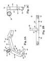
- FIG. 1A preferred embodiment of a surgical headframe 10 is provided in FIG. 1 as applied to a patient 11.
- the surgical headframe 10is for use with a stereotactic image guidance system (not shown), an example of which is available under the trade name LandmarX® from Medtronic-Xomed.
- the headframe 10includes a head frame body 12, swivel arms 14, a strap 16, and contact pads 18a-18c. Details on the various components are provided below. In general terms, however, the head frame body 12 is configured for placement about a patient's skull.
- the swivel arms 14extend from opposite sides of the frame body 12, respectively.
- the strap 16is connected to, and extends between, the swivel arms 14a, 14b.
- the contact pads 18a-18care secured to the frame body 12 as shown, positioned to precisely fixate the headframe 10 relative to the patient's skull.
- the surgical headframe 10is preferably configured to receive and rigidly maintain a dynamic reference frame (not shown), such as at a post or lug 20 otherwise formed by the frame body 12.
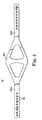
- the frame body 12is shown in greater detail in FIGS. 2A-2C.
- the frame body 12is preferably formed from a rigid, light-weight material, such as aluminum, and forms the post 20, a central portion 30, a first leg 32, and a second leg 34.
- the first and second legs 32, 34extend in opposite directions from the central portion 30, and are preferably identical in construction.
- each of the legs 32, 34includes a first section 36 and second section 38.
- the first section _36extends in an angular fashion from the central portion 30.
- the second section 38extends downwardly from the first section 36 (or rearwardly relative to the orientation of FIG. 2A) and defines an arm receiving region 40 and a pad receiving region 42.
- the arm receiving region 40is configured to receive a respective one of the swivel arms 14 (FIG. 1) at an engagement surface 58 via a lateral passage 44 formed therein.
- the pad receiving region 42is configured to receive a respective one of the contact pads 18 (FIG. 1) via a transverse bore 46 (best shown in FIG. 2C).
- the central portion 30similarly forms a transverse bore 48 for mounting of one of the contact pads 18 (FIG. 1).
- the frame body 12is highly planar or flat at an inner surface 50 thereof. That is to say, regardless of how the legs 32, 34 are formed relative to the central portion 30, the frame body 12 is, as a whole, planar at the inner surface 50. This preferred configuration is illustrated in FIGS.
- the swivel arm 14is preferably integrally formed from a rigid, light-weight material, such as aluminum, and is defined by a base 60, an intermediate section 62, and a leading end 64.
- the base 60is configured for mounting to the frame body 12 (FIG. 2) and defines an inner face 66 through which a passage 68 transversely extends.
- the base 60extends transversely relative to the intermediate section 62.
- the inner face 66is non-contiguous with a corresponding surface of the intermediate section 62 such that the inner face 66 is non-planar relative to the intermediate section 62.
- the intermediate section 62is depicted in FIG. 3A as including opposing shoulders 70 which are provided to receive and maintain auxiliary components (not shown). Alternatively, where the auxiliary components are unnecessary or are secured to other portions of the headframe 10, the shoulders 70 can be eliminated. Finally, the leading end 64 forms an opening 72 for receiving a pin (not shown) for securing the strap 16 (FIG. 1) to the swivel arm 14.
- the strap 16is shown in greater detail in FIG. 4.
- the strap 16is preferably formed of an elastic material, preferably silicone, and includes strips 80a, 80b extending in an opposing fashion from a central region 82.
- the strap 16is preferably sized for wrapping about a patient's head (not shown), and preferably has an overall length on the order of 21 inches.
- Each of the strips 80forms holes 84, sized for coupling to a pin (not shown) otherwise mounted to a respective one of the swivel arms 14 (FIG. 3).
- the central region 82preferably has an increased width relative to that of the strips 80, and is sized for placement over, or to straddle, the occipital bone. Alternatively, other configurations are equally acceptable.
- the opening 86is sized to receive a portion of the coupling device in a manner that allows convenient disassembly therefrom, such that after use, the contact pad 18 can easily be removed and discarded or recycled, with the coupling device available for re-use following appropriate cleaning/sterilization.
- the rim 92defines an outer diameter of the contact pad 18, preferably approximately 5.08 cm (2 inches) in diameter, it being understood that a wide variety of other dimensions, either greater or smaller, are equally acceptable.
- the contact surface 94extends in a generally concave fashion from the rim 92. With this curved configuration, in conjunction with the durometer of the material selected for the contact pad 18, optimal comfort is provided to the patient, while providing maximum stability.
- each of the contact pads 18a-18ccan be maneuvered or swiveled relative to the frame body 12 so as to accommodate a particular patient's head shape.
- the contact pads 18a-18care arranged in a triangular or "tripod" fashion, with the contact pads 18a, 18c being equidistantly spaced from the contact pad 18b.
- This triangular arrangement of the contact pads 18a-18cprovides greatly enhanced lateral stability relative to a two-pad design, thereby restricting overall motion of the individual contact pads 18.
- each of the swivel arms 14is mounted to the frame body 12 by a coupling device 100 including a threaded pin 102 and a head 104.
- the pin 102extends through the lateral passage 44 associated with the arm receiving region 40 of the frame body 12 and threadably engages the passage 68 formed in the base 60 of the respective swivel arm 14.
- the head 104is preferably configured to provide convenient grasping by a surgeon who rotates the head 104 to thread the pin 102 into the base 60.
- the engagement surface 58 and the inner face 66are preferably flat such that, where desired, the swivel arm 14 can freely rotate relative to the frame body 12 about the pin 102.
- the swivel arms 14a, 14bare preferably assembled to allow for 360° movement relative to the frame body 12. During use, this preferred construction eliminates bending movements or forces from transferring from the step 16 (FIG. 1) through the respective pins 102 to the frame body 12 that might otherwise cause the headframe 10 (FIG. 1) to slip or move from a desired position.
- the surgical headframe 10is secured to a patient's head 120 (preferably the forehead) by first locating the contact pads 18 against the head 120. As previously described, the concave nature of the contact pads 18 facilitates "gripping" of the contact pads 18 to the head 120.
- the swivel arms 14extend rearwardly relative to the patient's head 120, substantially along the patient's temple, or slightly above the ears.
- the strap 16is then wrapped behind the patient's head 120, much like a diving mask, and secured to the retention pins 110a, 110b via the holes 84.
- the central region 82 (FIG. 4) of the strap 16is placed over the occilipate bone (not shown). Alternatively, other locations of the strap 16 relative to the patient's head 120 can be employed. Regardless, due to the elastic nature of the strap 16, the surgical headframe 10 can be tightly positioned or forced against the patient's head 120.
- the contact pads 18can swivel slightly to match the contours of the patient's head 120. Further, the triangular or tripod-like arrangement of the contact pads 18 renders the surgical headframe 10 highly stable relative to the patient's head 120. That is to say, the triangular orientation provides stability in all planes, and specifically prevents "rocking" of the headframe 10 along any one axis. Additionally, the contact pad 18b associated with the central portion 30 of the frame body 12 is offset from the plane in which the strap 16 wraps about the patient's head 120. As a result, the contact pad 18b effectively stretches the skin engaged by the contact pad 18b, further enhancing overall stability.
- the surgical headframe 10is available for receiving and maintaining other components of the stereotactic system.
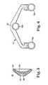
- a dynamic reference frame 130 and a touch pad 132are preferably secured to the post 20 as shown in FIG. 8.
- the dynamic reference frame 130maintains one or more optical emitters 134 (shown generally in FIG. 8) that are utilized by the stereotactic system during surgical procedures.
- the dynamic reference frame 130is rigidly secured to the surgical headframe 10 via the post 20.
- the surgical headframe 10is fixed to the patient's head 120 (FIG. 1).
- the dynamic reference frame 130is rigidly associated with the patient's head 120, and establishes a consistent reference zone even with movement of the patient's head 120.
- the touch pad 132is an auxiliary device available to provide the surgeon with the ability to effectuate changes in the use/display of the stereotactic system. It should be understood, however, that the touch pad 132 is not a required element of the present invention, and can be secured to areas other than the post 20.
- the surgical headframe of the present inventionprovides a marked improvement over previous designs. Fixation of the surgical headframe to a patient's head is non-invasive as it does not entail the use of bone screws or other incisions through the patient's skin. Further, as compared to clamp-type headframe designs, use of soft contact pads against the patient's skin greatly reduces the opportunity for trauma. Finally, by preferably orientating three contact pads in a triangular or tripod configuration, the headframe is highly stable in all dimensions.
- the frame body and swivel armsneed not be made from aluminum. Instead, a wide variety of other materials are available.
- the frame body and swivel arms(as well as other components of the headframe) are formed of a non-magnetic material such as plastic, ceramic, or other composite such that the headframe is compatible with MRI, CT, X-ray and magnetic stereotactic devices/procedures.
Landscapes
- Health & Medical Sciences (AREA)
- Surgery (AREA)
- Life Sciences & Earth Sciences (AREA)
- Biomedical Technology (AREA)
- Medical Informatics (AREA)
- Oral & Maxillofacial Surgery (AREA)
- Nuclear Medicine, Radiotherapy & Molecular Imaging (AREA)
- Engineering & Computer Science (AREA)
- Neurosurgery (AREA)
- Heart & Thoracic Surgery (AREA)
- Pathology (AREA)
- Molecular Biology (AREA)
- Animal Behavior & Ethology (AREA)
- General Health & Medical Sciences (AREA)
- Public Health (AREA)
- Veterinary Medicine (AREA)
- Apparatus For Radiation Diagnosis (AREA)
- Microscoopes, Condenser (AREA)
Abstract
Description
the plurality of contact pads includes first, second and third contact pads;
the arrangement of the first, second, and third contact pads defining acoplanar tripod, each contact pad adapted to engage a patient's forehead.
first, second, and third contact pads are coupled to the frame body; and
wherein coupling the contact pads to the frame body includes locating thefirst, second and third contact pads in a coplanar tripod arrangement.
Claims (35)
- A surgical headframe (10) for maintaining a stereotactic system referenceframe relative to a patient's head, the headframe comprising:wherein the headframe is adapted to receive and maintain a stereotactic referenceframe;characterised in thata frame body (12) defining a first and second arm receiving portion (40), thefirst arm receiving portion positioned opposite the second arm receiving portion;first and second arms (14) extending from and being rotatable relative to thefirst and second arm receiving portions respectively of the frame body;a plurality of contact pads (18a-18c) coupled to the frame body; anda strap (16) connectible to the first and second arms, the strap adapted forwrapping about a back of a patient's head;
the plurality of contact pads includes first, second and third contact pads;
the arrangement of the first, second, and third contact pads defining acoplanar tripod, each contact pad adapted to engage a patient's forehead. - The headframe of claim 1, wherein the first contact pad is coupled to acentral portion of the frame body, and the second and third contact pads arepositioned opposite one another relative to the first contact pad.
- The headframe of claim 2, wherein the second and third contact pads areequidistantly spaced from the first contact pad.
- The headframe of any preceding claim, wherein a center point spacingbetween the second and third contact pads is 10.478 cm (4.125 inches).
- The headframe of any preceding claim wherein a lateral, center pointspacing between the first and second contact pads is 5.715 cm (2.25 inches).
- The headframe of any preceding claim, wherein each of the contact pads(18a-18c) is pivotally coupled to the frame body.
- The headframe of any preceding claim, wherein each of the contact pads(18a-18c) defines a contact surface adapted for contacting a patient's head, andfurther wherein the contact pads are arranged such that the respective contactsurfaces are co-planar.
- The headframe of any preceding claim, wherein each of the contact pads(18a-18c) has an outer diameter of approximately 5.08 cm (2 inches).
- The headframe of any preceding claim, wherein each of the contact pads(18a-18c) defines a concave contact surface adapted for contacting a patient's head.
- The headframe of any preceding claim, wherein the first and second arms(14) each include:a base (60) defining an inner face (66) for contacting a correspondingsurface of the frame body;an intermediate section (62) extending from the base, wherein extension ofthe intermediate section is non-planar relative to the inner face; anda leading end (64) extending from the intermediate section opposite the base.
- The headframe of claim 10, wherein extension of the inner face (66) definesan acute angle relative to a plane of the intermediate section.
- The headframe of claim 10, wherein the inner face (66) is flat.
- The headframe of claim 10, 11 or 12, wherein the base (60) forms atransverse passage for receiving a mounting device that rotatably couples therespective arm to the frame body.
- The headframe of claim 10, 11, 12 or 13, wherein the intermediate section(62) forms opposing shoulders (70) each adapted for receiving an auxiliarycomponent.
- The headframe of any preceding claim, wherein each of the first and secondarms (14) includes a pin for retaining a portion of the strap.
- The headframe of claim 15, wherein the pin extends from the leading end.
- The headframe of any preceding claim, wherein the frame body (12)includes:wherein the first and second legs extend in opposite directions from thecentral portion.a central portion (30);a first leg (32); anda second leg (34);
- The headframe of claim 17, wherein the central portion (30), the first leg(32) and the second leg (34) combined to define a planer inner surface adapted forcoupling to the contact pads.
- The headframe of claim 17 or 18, wherein each of the central portion (30),the first leg (32), and the second leg (34) are adapted to maintain a respective one ofthe contact pads (18a-18c).
- The headframe of claim 17, 18 or 19 wherein the first and second legs (32,34) are symmetrically arranged relative to the central portion (30).
- The head frame of any of claims 17 to 20, wherein each of the central portion(30), the first leg (32), and the second leg (34) form a bore (48) adapted forreceiving a contact pad coupling device, and further wherein the bores of the firstand second legs are equidistantly spaced from the bore of the central portion.
- The headframe of any of claims 17 to 21, wherein each of the second legs(34) includes:a first section (36) extending in an angular fashion from the central portion;anda second section (38) extending downwardly from the first section.
- The headframe of claim 22, wherein the second section defines:said arm receiving portion (40) adapted to maintain a respective one of thefirst and second arms; anda pad receiving portion (42) adapted to maintain a respective one of thecontact pads.
- The headframe of any preceding claim, wherein the arm receiving portion(40) includes a flat engagement surface (58) for abutting a corresponding surface ofa respective one of the first and second arms.
- The head frame of any of claims 17 to 24, wherein a respective one of thecontact pads (18a-18c) extends from an inner surface of the central portion, the frame body further including a post (20) extending from the central portion oppositethe inner surface, the post being adapted to receive the reference frame.
- The headframe of any preceding claim, wherein the strap (16) includes:wherein the first and second strips extend in an opposing fashion from thecentral region.a central region (82);a first strip (80a); anda second strip (80b);
- The headframe of claim 26, wherein each of the strips forms a plurality ofholes (84) adapted for selectively coupling the respective strip to a respective one ofthe arms.
- The headframe of claim 26 or 27, wherein the central region is adapted forplacement over an occipital bone of a patient's head.
- The headframe of any preceding claim, further comprising:a control pad (132) adapted to facilitate control over a stereotactic procedure,the control pad being mounted to the frame body.
- A method of manufacturing a surgical headframe for use in a stereotacticprocedure, the method comprising:wherein the headframe is adapted to receive and maintain a stereotacticreference frame;characterised in thatproviding a frame body (12) including a central portion and opposing sideshaving, respectively, first and second arm receiving portions (40);extending first and second arms (14) from the first and second arm receivingportions of the frame body, respectively, said first and second arms (14) beingrotatable relative to the first and second arm receiving portions, respectively;coupling a plurality of contact pads (18a-18c) to the frame body, the contactpads each adapted to engage a patient's forehead; andselectively securing a strap (16) to the first and second arms opposite theframe body, the strap adapted for wrapping about a back of a patient's head;
first, second, and third contact pads (18a-18c) are coupled to the frame body;and
wherein coupling the contact pads to the frame body includes locating the first, second and third contact pads in a coplanar tripod arrangement. - The method of claim 30, wherein coupling the contact pads to the framebody includes coupling the first contact pad to the central portion of the frame bodyand positioning the second and third contact pads opposite one another relative tothe first contact pad.
- The method of claim 30 or 31, wherein coupling the contact pads includespivotally mounting at least one of the contact pads to the frame body.
- The method of any of claims 30 to 32, wherein selectively securing a strap(16) to the first and second arms includes:wherein the holes are sized to be received over the respective pins.providing the strap with a plurality of holes (84); andextending a pin from each of the arms, respectively;
- The method of any of claims 30 to 33, further comprising:providing the frame body with a post (20) adapted to receive a stereotactic referenceframe.
- The method of any of claims 30 to 34, further comprising:mounting a control pad (132) to the frame body, the control pad adapted tofacilitate control over a stereotactic procedure.
Applications Claiming Priority (3)
| Application Number | Priority Date | Filing Date | Title |
|---|---|---|---|
| US23521500P | 2000-09-24 | 2000-09-24 | |
| US235215P | 2000-09-24 | ||
| PCT/US2001/029763WO2002024096A1 (en) | 2000-09-24 | 2001-09-24 | Surgical headrframe with soft contact pads for use with a stereotactic system |
Publications (2)
| Publication Number | Publication Date |
|---|---|
| EP1322247A1 EP1322247A1 (en) | 2003-07-02 |
| EP1322247B1true EP1322247B1 (en) | 2005-04-06 |
Family
ID=22884582
Family Applications (1)
| Application Number | Title | Priority Date | Filing Date |
|---|---|---|---|
| EP01975316AExpired - LifetimeEP1322247B1 (en) | 2000-09-24 | 2001-09-24 | Surgical headrframe with soft contact pads for use with a stereotactic system |
Country Status (5)
| Country | Link |
|---|---|
| US (1) | US6770082B2 (en) |
| EP (1) | EP1322247B1 (en) |
| AT (1) | ATE292424T1 (en) |
| DE (1) | DE60109949T2 (en) |
| WO (1) | WO2002024096A1 (en) |
Families Citing this family (39)
| Publication number | Priority date | Publication date | Assignee | Title |
|---|---|---|---|---|
| US7547307B2 (en) | 2001-02-27 | 2009-06-16 | Smith & Nephew, Inc. | Computer assisted knee arthroplasty instrumentation, systems, and processes |
| WO2002091915A1 (en)* | 2001-05-17 | 2002-11-21 | Oticon A/S | Method and apparatus for obtaining position data relating to a probe in the ear canal |
| JP2005516724A (en) | 2002-02-11 | 2005-06-09 | スミス アンド ネフュー インコーポレーテッド | Image guided fracture reduction |
| SE524261C2 (en)* | 2002-05-08 | 2004-07-20 | Elekta Ab | Device for fixing to a patient's head during MRI diagnostics, a pin support member, an isolation device for fixing pins, and a method of assembling a fixing device |
| US20030232550A1 (en)* | 2002-06-18 | 2003-12-18 | Wagner John Lee | Universal swim fin replacement heel strap |
| US7507244B2 (en) | 2003-02-10 | 2009-03-24 | Integra Lifesciences Corporation | Radiolucent skull clamp with removable pin load applicator |
| JP4303502B2 (en)* | 2003-03-31 | 2009-07-29 | 英明 長沼 | Linear acceleration stimulator |
| US7862570B2 (en) | 2003-10-03 | 2011-01-04 | Smith & Nephew, Inc. | Surgical positioners |
| EP1522267B1 (en) | 2003-10-06 | 2009-01-14 | Stryker Trauma SA | External fixation elements |
| US7764985B2 (en) | 2003-10-20 | 2010-07-27 | Smith & Nephew, Inc. | Surgical navigation system component fault interfaces and related processes |
| ATE495706T1 (en) | 2003-11-14 | 2011-02-15 | Smith & Nephew Inc | ADJUSTABLE SURGICAL CUTTING SYSTEMS |
| US7117551B1 (en) | 2003-12-01 | 2006-10-10 | Integra Ohio, Inc. | Head support system |
| US7730563B1 (en)* | 2004-03-29 | 2010-06-08 | Frederick Sklar | Head support and stabilization system |
| CA2561493A1 (en) | 2004-03-31 | 2005-10-20 | Smith & Nephew, Inc. | Methods and apparatuses for providing a reference array input device |
| EP1737375B1 (en) | 2004-04-21 | 2021-08-11 | Smith & Nephew, Inc | Computer-aided navigation systems for shoulder arthroplasty |
| US20060150984A1 (en)* | 2005-01-07 | 2006-07-13 | Ferguson Joe W | Surgical head fixation and positioning system |
| WO2006091704A1 (en) | 2005-02-22 | 2006-08-31 | Smith & Nephew, Inc. | In-line milling system |
| WO2007087668A1 (en)* | 2006-01-31 | 2007-08-09 | Ellysian Ltd | Positioning bracket |
| US8301226B2 (en)* | 2007-04-24 | 2012-10-30 | Medtronic, Inc. | Method and apparatus for performing a navigated procedure |
| US9289270B2 (en)* | 2007-04-24 | 2016-03-22 | Medtronic, Inc. | Method and apparatus for performing a navigated procedure |
| US20090012509A1 (en)* | 2007-04-24 | 2009-01-08 | Medtronic, Inc. | Navigated Soft Tissue Penetrating Laser System |
| US8108025B2 (en)* | 2007-04-24 | 2012-01-31 | Medtronic, Inc. | Flexible array for use in navigated surgery |
| US8734466B2 (en)* | 2007-04-25 | 2014-05-27 | Medtronic, Inc. | Method and apparatus for controlled insertion and withdrawal of electrodes |
| US8311611B2 (en)* | 2007-04-24 | 2012-11-13 | Medtronic, Inc. | Method for performing multiple registrations in a navigated procedure |
| WO2009006935A1 (en)* | 2007-07-06 | 2009-01-15 | Karolinska Institutet Innovations Ab | Stereotactic surgery system |
| EP2164419A1 (en)* | 2007-11-08 | 2010-03-24 | Orthosoft, Inc. | Trackable reference device for computer-assisted surgery |
| DE112009001275T5 (en)* | 2008-06-05 | 2011-04-14 | Dinkler Surgical Devices, Inc., Dayton | Head fixation device |
| GB0905352D0 (en) | 2009-03-30 | 2009-05-13 | Barking Havering And Redbridge | Device |
| EP2523624B1 (en)* | 2010-01-11 | 2016-04-06 | Frederick Sklar | Pediatric headrest for skull stabilization and method for use of same |
| EP2868288B1 (en)* | 2013-10-31 | 2018-06-20 | ELEKTA AB (publ.) | A frame for fixation of equipment to the head of a patient during neurological diagnosis, stereotactic imaging, therapy or surgery |
| US20160106508A1 (en)* | 2014-10-15 | 2016-04-21 | Vanderbilt University | Structure for supporting a medical device on a patient during surgical procedures |
| US10716730B2 (en)* | 2015-01-22 | 2020-07-21 | Ovard, Llc | Gaze stabilization system and method |
| EP3261572B1 (en)* | 2016-05-20 | 2018-08-01 | Brainlab AG | Tracking reference fixation support |
| TWI629974B (en)* | 2017-05-26 | 2018-07-21 | 醫百科技股份有限公司 | Surgical guidance system |
| CN112890924B (en)* | 2021-01-04 | 2023-05-23 | 山东盛原康医疗器械有限公司 | Method for accurately positioning focus of patient |
| US12345373B2 (en) | 2022-11-07 | 2025-07-01 | Frederick H. Sklar | Base station assembly for an operating room table |
| US12082981B2 (en) | 2022-11-07 | 2024-09-10 | Frederick H. Sklar | Surgical armrest |
| US12083052B2 (en) | 2022-11-07 | 2024-09-10 | Frederick H. Sklar | Surgical universal headrest including skull pin holder assembly |
| LT7074B (en) | 2022-12-07 | 2024-07-25 | Kauno technologijos universitetas | Stereotactic frame positioning system |
Family Cites Families (17)
| Publication number | Priority date | Publication date | Assignee | Title |
|---|---|---|---|---|
| US841714A (en)* | 1906-01-18 | 1907-01-22 | Walter D Peters | Head-truss. |
| US937596A (en)* | 1909-03-26 | 1909-10-19 | Clyde Gray | Headache appliance. |
| US999945A (en)* | 1910-07-19 | 1911-08-08 | Hermann Aub | Head-electrifying device. |
| DE869843C (en)* | 1951-03-28 | 1953-03-09 | C Erbe Fa | Holder for the base frame of a target device for neurosurgery |
| US4360028A (en)* | 1980-01-14 | 1982-11-23 | Barbier Jean Y | Cranial insertion of surgical needle utilizing computer-assisted tomography |
| US4797736A (en)* | 1987-09-02 | 1989-01-10 | Luxtec Corporation | Head mounted illumination and camera assembly |
| DE59207799D1 (en) | 1991-10-04 | 1997-02-13 | Zeiss Carl Fa | Headband for a measuring, lighting or observation unit |
| US5207688A (en)* | 1991-10-31 | 1993-05-04 | Medco, Inc. | Noninvasive head fixation method and apparatus |
| US5330485A (en)* | 1991-11-01 | 1994-07-19 | Clayman David A | Cerebral instrument guide frame and procedures utilizing it |
| US5388580A (en) | 1992-08-19 | 1995-02-14 | The United States Of America As Represented By The Department Of Health And Human Services | Head holder for magnetic resonance imaging/spectroscopy system |
| US5387220A (en) | 1993-06-15 | 1995-02-07 | Pisharodi; Maohaven | Stereotactic frame and localization method |
| US6096048A (en) | 1994-04-20 | 2000-08-01 | Howard, Iii; Matthew A. | Noninvasive, reattachable skull fiducial marker system |
| DE69531994T2 (en) | 1994-09-15 | 2004-07-22 | OEC Medical Systems, Inc., Boston | SYSTEM FOR POSITION DETECTION BY MEANS OF A REFERENCE UNIT ATTACHED TO A PATIENT'S HEAD FOR USE IN THE MEDICAL AREA |
| JP2611188B2 (en)* | 1994-11-30 | 1997-05-21 | 工業技術院長 | Biological measurement reference point setting method and apparatus |
| AU6907696A (en) | 1995-08-18 | 1997-03-12 | Brigham And Women's Hospital | Versatile stereotactic device and methods of use |
| US5649936A (en) | 1995-09-19 | 1997-07-22 | Real; Douglas D. | Stereotactic guide apparatus for use with neurosurgical headframe |
| US6594839B1 (en)* | 1999-04-30 | 2003-07-22 | The Cleveland Clinic Foundation | Surgical headrest |
- 2001
- 2001-09-24EPEP01975316Apatent/EP1322247B1/ennot_activeExpired - Lifetime
- 2001-09-24ATAT01975316Tpatent/ATE292424T1/ennot_activeIP Right Cessation
- 2001-09-24USUS09/961,569patent/US6770082B2/ennot_activeExpired - Lifetime
- 2001-09-24DEDE60109949Tpatent/DE60109949T2/ennot_activeExpired - Lifetime
- 2001-09-24WOPCT/US2001/029763patent/WO2002024096A1/enactiveIP Right Grant
Also Published As
| Publication number | Publication date |
|---|---|
| EP1322247A1 (en) | 2003-07-02 |
| ATE292424T1 (en) | 2005-04-15 |
| WO2002024096A1 (en) | 2002-03-28 |
| US20020042619A1 (en) | 2002-04-11 |
| US6770082B2 (en) | 2004-08-03 |
| DE60109949T2 (en) | 2006-02-16 |
| DE60109949D1 (en) | 2005-05-12 |
Similar Documents
| Publication | Publication Date | Title |
|---|---|---|
| EP1322247B1 (en) | Surgical headrframe with soft contact pads for use with a stereotactic system | |
| JP4248631B2 (en) | Surgical instrument support device | |
| US9717529B2 (en) | Orthopedic external fixation device | |
| WO2017189427A1 (en) | Systems, devices, and methods for tracking and compensating for patient motion during a medical imaging scan | |
| US10959741B2 (en) | Bone fixation system, assembly, devices, insertion guides, and methods of use | |
| US20060155293A1 (en) | External rotation cut guide | |
| JP2017512597A (en) | Reference device for surgical navigation system | |
| TWI399192B (en) | Universal direction medical positioning structure | |
| US20220015807A1 (en) | Occipital Plate With Angled Screw Opening | |
| US20030131852A1 (en) | Registration and surgical face mask | |
| US20050075560A1 (en) | Stereotactic frame and method for supporting a stereotactic frame | |
| Duque et al. | Endoscopic endonasal transphenoidal surgery using the BrainLAB® Headband for navigation without rigid fixation | |
| ES2340574T3 (en) | FRACTURE FIXING SYSTEM WITH AN ELASTIC CHASSIS. | |
| JP2002172120A (en) | Stereotactic tool | |
| US6491700B1 (en) | Method for readjusting medical images on a patient and associated device | |
| JP3430256B2 (en) | Animal head fixation device for magnetic resonance imaging | |
| CA2717662A1 (en) | Non-invasive dental based animal fiducial array | |
| RU210665U1 (en) | Marker holder for performing surgery on the patient's head using mixed reality | |
| Greenfield et al. | Endoscopic endonasal transsphenoidal surgery using a skull reference array and laser surface scanning | |
| CN109833093B (en) | Navigation locator fixing device for anterior cervical surgery | |
| JP3112956U (en) | Stereotaxic frame mounting device | |
| RU2809175C1 (en) | Marker holder for preparing and performing surgery using mixed reality technology | |
| TWM503195U (en) | Miniature three-dimensional alignment mark | |
| CN218606797U (en) | A bone reduction clamp and surgical forceps | |
| JP2024175040A (en) | Rocker arm assembly for head immobilization device |
Legal Events
| Date | Code | Title | Description |
|---|---|---|---|
| PUAI | Public reference made under article 153(3) epc to a published international application that has entered the european phase | Free format text:ORIGINAL CODE: 0009012 | |
| 17P | Request for examination filed | Effective date:20030423 | |
| AK | Designated contracting states | Designated state(s):AT BE CH CY DE DK ES FI FR GB GR IE IT LI LU MC NL PT SE TR | |
| 17Q | First examination report despatched | Effective date:20030718 | |
| RAP1 | Party data changed (applicant data changed or rights of an application transferred) | Owner name:MEDTRONIC, INC. | |
| GRAP | Despatch of communication of intention to grant a patent | Free format text:ORIGINAL CODE: EPIDOSNIGR1 | |
| GRAS | Grant fee paid | Free format text:ORIGINAL CODE: EPIDOSNIGR3 | |
| GRAA | (expected) grant | Free format text:ORIGINAL CODE: 0009210 | |
| AK | Designated contracting states | Kind code of ref document:B1 Designated state(s):AT BE CH CY DE DK ES FI FR GB GR IE IT LI LU MC NL PT SE TR | |
| PG25 | Lapsed in a contracting state [announced via postgrant information from national office to epo] | Ref country code:IT Free format text:LAPSE BECAUSE OF FAILURE TO SUBMIT A TRANSLATION OF THE DESCRIPTION OR TO PAY THE FEE WITHIN THE PRESCRIBED TIME-LIMIT;WARNING: LAPSES OF ITALIAN PATENTS WITH EFFECTIVE DATE BEFORE 2007 MAY HAVE OCCURRED AT ANY TIME BEFORE 2007. THE CORRECT EFFECTIVE DATE MAY BE DIFFERENT FROM THE ONE RECORDED. Effective date:20050406 Ref country code:FI Free format text:LAPSE BECAUSE OF FAILURE TO SUBMIT A TRANSLATION OF THE DESCRIPTION OR TO PAY THE FEE WITHIN THE PRESCRIBED TIME-LIMIT Effective date:20050406 Ref country code:CH Free format text:LAPSE BECAUSE OF FAILURE TO SUBMIT A TRANSLATION OF THE DESCRIPTION OR TO PAY THE FEE WITHIN THE PRESCRIBED TIME-LIMIT Effective date:20050406 Ref country code:AT Free format text:LAPSE BECAUSE OF FAILURE TO SUBMIT A TRANSLATION OF THE DESCRIPTION OR TO PAY THE FEE WITHIN THE PRESCRIBED TIME-LIMIT Effective date:20050406 Ref country code:BE Free format text:LAPSE BECAUSE OF FAILURE TO SUBMIT A TRANSLATION OF THE DESCRIPTION OR TO PAY THE FEE WITHIN THE PRESCRIBED TIME-LIMIT Effective date:20050406 Ref country code:NL Free format text:LAPSE BECAUSE OF FAILURE TO SUBMIT A TRANSLATION OF THE DESCRIPTION OR TO PAY THE FEE WITHIN THE PRESCRIBED TIME-LIMIT Effective date:20050406 Ref country code:LI Free format text:LAPSE BECAUSE OF FAILURE TO SUBMIT A TRANSLATION OF THE DESCRIPTION OR TO PAY THE FEE WITHIN THE PRESCRIBED TIME-LIMIT Effective date:20050406 Ref country code:TR Free format text:LAPSE BECAUSE OF FAILURE TO SUBMIT A TRANSLATION OF THE DESCRIPTION OR TO PAY THE FEE WITHIN THE PRESCRIBED TIME-LIMIT Effective date:20050406 | |
| REG | Reference to a national code | Ref country code:GB Ref legal event code:FG4D | |
| REG | Reference to a national code | Ref country code:CH Ref legal event code:EP | |
| REG | Reference to a national code | Ref country code:IE Ref legal event code:FG4D | |
| REF | Corresponds to: | Ref document number:60109949 Country of ref document:DE Date of ref document:20050512 Kind code of ref document:P | |
| PG25 | Lapsed in a contracting state [announced via postgrant information from national office to epo] | Ref country code:GR Free format text:LAPSE BECAUSE OF FAILURE TO SUBMIT A TRANSLATION OF THE DESCRIPTION OR TO PAY THE FEE WITHIN THE PRESCRIBED TIME-LIMIT Effective date:20050706 Ref country code:DK Free format text:LAPSE BECAUSE OF FAILURE TO SUBMIT A TRANSLATION OF THE DESCRIPTION OR TO PAY THE FEE WITHIN THE PRESCRIBED TIME-LIMIT Effective date:20050706 Ref country code:SE Free format text:LAPSE BECAUSE OF FAILURE TO SUBMIT A TRANSLATION OF THE DESCRIPTION OR TO PAY THE FEE WITHIN THE PRESCRIBED TIME-LIMIT Effective date:20050706 | |
| PG25 | Lapsed in a contracting state [announced via postgrant information from national office to epo] | Ref country code:ES Free format text:LAPSE BECAUSE OF FAILURE TO SUBMIT A TRANSLATION OF THE DESCRIPTION OR TO PAY THE FEE WITHIN THE PRESCRIBED TIME-LIMIT Effective date:20050717 | |
| PG25 | Lapsed in a contracting state [announced via postgrant information from national office to epo] | Ref country code:PT Free format text:LAPSE BECAUSE OF FAILURE TO SUBMIT A TRANSLATION OF THE DESCRIPTION OR TO PAY THE FEE WITHIN THE PRESCRIBED TIME-LIMIT Effective date:20050908 | |
| PG25 | Lapsed in a contracting state [announced via postgrant information from national office to epo] | Ref country code:CY Free format text:LAPSE BECAUSE OF FAILURE TO SUBMIT A TRANSLATION OF THE DESCRIPTION OR TO PAY THE FEE WITHIN THE PRESCRIBED TIME-LIMIT Effective date:20050924 | |
| PG25 | Lapsed in a contracting state [announced via postgrant information from national office to epo] | Ref country code:IE Free format text:LAPSE BECAUSE OF NON-PAYMENT OF DUE FEES Effective date:20050926 | |
| PG25 | Lapsed in a contracting state [announced via postgrant information from national office to epo] | Ref country code:MC Free format text:LAPSE BECAUSE OF NON-PAYMENT OF DUE FEES Effective date:20050930 Ref country code:LU Free format text:LAPSE BECAUSE OF NON-PAYMENT OF DUE FEES Effective date:20050930 | |
| NLV1 | Nl: lapsed or annulled due to failure to fulfill the requirements of art. 29p and 29m of the patents act | ||
| REG | Reference to a national code | Ref country code:CH Ref legal event code:PL | |
| PLBE | No opposition filed within time limit | Free format text:ORIGINAL CODE: 0009261 | |
| STAA | Information on the status of an ep patent application or granted ep patent | Free format text:STATUS: NO OPPOSITION FILED WITHIN TIME LIMIT | |
| 26N | No opposition filed | Effective date:20060110 | |
| ET | Fr: translation filed | ||
| REG | Reference to a national code | Ref country code:IE Ref legal event code:MM4A | |
| PGFP | Annual fee paid to national office [announced via postgrant information from national office to epo] | Ref country code:GB Payment date:20140929 Year of fee payment:14 | |
| GBPC | Gb: european patent ceased through non-payment of renewal fee | Effective date:20150924 | |
| PG25 | Lapsed in a contracting state [announced via postgrant information from national office to epo] | Ref country code:GB Free format text:LAPSE BECAUSE OF NON-PAYMENT OF DUE FEES Effective date:20150924 | |
| REG | Reference to a national code | Ref country code:FR Ref legal event code:PLFP Year of fee payment:16 | |
| REG | Reference to a national code | Ref country code:FR Ref legal event code:PLFP Year of fee payment:17 | |
| REG | Reference to a national code | Ref country code:FR Ref legal event code:PLFP Year of fee payment:18 | |
| PGFP | Annual fee paid to national office [announced via postgrant information from national office to epo] | Ref country code:DE Payment date:20190820 Year of fee payment:19 Ref country code:FR Payment date:20190820 Year of fee payment:19 | |
| REG | Reference to a national code | Ref country code:DE Ref legal event code:R082 Ref document number:60109949 Country of ref document:DE Representative=s name:FORTMANN TEGETHOFF PATENT- UND RECHTSANWAELTE, DE | |
| REG | Reference to a national code | Ref country code:DE Ref legal event code:R119 Ref document number:60109949 Country of ref document:DE | |
| PG25 | Lapsed in a contracting state [announced via postgrant information from national office to epo] | Ref country code:DE Free format text:LAPSE BECAUSE OF NON-PAYMENT OF DUE FEES Effective date:20210401 Ref country code:FR Free format text:LAPSE BECAUSE OF NON-PAYMENT OF DUE FEES Effective date:20200930 |