EP1320328B1 - Needle package with point guards - Google Patents
Needle package with point guardsDownload PDFInfo
- Publication number
- EP1320328B1 EP1320328B1EP01944601AEP01944601AEP1320328B1EP 1320328 B1EP1320328 B1EP 1320328B1EP 01944601 AEP01944601 AEP 01944601AEP 01944601 AEP01944601 AEP 01944601AEP 1320328 B1EP1320328 B1EP 1320328B1
- Authority
- EP
- European Patent Office
- Prior art keywords
- package
- point
- retaining member
- pointed
- supporting portion
- Prior art date
- Legal status (The legal status is an assumption and is not a legal conclusion. Google has not performed a legal analysis and makes no representation as to the accuracy of the status listed.)
- Expired - Lifetime
Links
- 230000002093peripheral effectEffects0.000claimsdescription7
- 230000000994depressogenic effectEffects0.000claims7
- 230000000295complement effectEffects0.000claims2
- 238000010276constructionMethods0.000claims2
- QAOWNCQODCNURD-UHFFFAOYSA-LSulfateChemical compound[O-]S([O-])(=O)=OQAOWNCQODCNURD-UHFFFAOYSA-L0.000claims1
- 230000000149penetrating effectEffects0.000claims1
- 239000003292glueSubstances0.000description5
- 239000012528membraneSubstances0.000description5
- 238000007789sealingMethods0.000description5
- 210000003811fingerAnatomy0.000description4
- 238000004806packaging method and processMethods0.000description4
- 239000000463materialSubstances0.000description3
- 239000004033plasticSubstances0.000description2
- 229920003023plasticPolymers0.000description2
- -1polypropylenePolymers0.000description2
- 239000004698PolyethyleneSubstances0.000description1
- 239000004743PolypropyleneSubstances0.000description1
- 239000004793PolystyreneSubstances0.000description1
- 239000004775TyvekSubstances0.000description1
- 229920000690TyvekPolymers0.000description1
- 239000000853adhesiveSubstances0.000description1
- 230000001070adhesive effectEffects0.000description1
- XAGFODPZIPBFFR-UHFFFAOYSA-NaluminiumChemical compound[Al]XAGFODPZIPBFFR-UHFFFAOYSA-N0.000description1
- 229910052782aluminiumInorganic materials0.000description1
- 230000001174ascending effectEffects0.000description1
- 238000007796conventional methodMethods0.000description1
- 238000006073displacement reactionMethods0.000description1
- 238000005516engineering processMethods0.000description1
- 238000002347injectionMethods0.000description1
- 239000007924injectionSubstances0.000description1
- 230000003993interactionEffects0.000description1
- 230000002452interceptive effectEffects0.000description1
- 238000012986modificationMethods0.000description1
- 230000004048modificationEffects0.000description1
- 238000004023plastic weldingMethods0.000description1
- 229920000573polyethylenePolymers0.000description1
- 229920001155polypropylenePolymers0.000description1
- 229920002223polystyrenePolymers0.000description1
- 230000001681protective effectEffects0.000description1
- 230000000452restraining effectEffects0.000description1
- 230000035939shockEffects0.000description1
- 238000001356surgical procedureMethods0.000description1
- 210000003813thumbAnatomy0.000description1
Images


Classifications
- A—HUMAN NECESSITIES
- A61—MEDICAL OR VETERINARY SCIENCE; HYGIENE
- A61B—DIAGNOSIS; SURGERY; IDENTIFICATION
- A61B17/00—Surgical instruments, devices or methods
- A61B17/04—Surgical instruments, devices or methods for suturing wounds; Holders or packages for needles or suture materials
- A61B17/06—Needles ; Sutures; Needle-suture combinations; Holders or packages for needles or suture materials
- A61B17/06114—Packages or dispensers for needles or sutures
- A61B17/06133—Packages or dispensers for needles or sutures of parallelepipedal shape, e.g. made of rectangular or slightly oval panels
- A—HUMAN NECESSITIES
- A61—MEDICAL OR VETERINARY SCIENCE; HYGIENE
- A61B—DIAGNOSIS; SURGERY; IDENTIFICATION
- A61B17/00—Surgical instruments, devices or methods
- A61B17/04—Surgical instruments, devices or methods for suturing wounds; Holders or packages for needles or suture materials
- A61B17/06—Needles ; Sutures; Needle-suture combinations; Holders or packages for needles or suture materials
- A61B17/06114—Packages or dispensers for needles or sutures
- A61B2017/06142—Packages or dispensers for needles or sutures having needle- or suture- retaining members, e.g. holding tabs or needle parks
Definitions
- the present inventionrelates to packages for sterile pointed objects, such as needles, and more particularly to thermoformed blister packages for such objects.
- Blister packs for needlesare well known and used due to their effectiveness and economy.
- Pointed devicessuch as needles, especially heavy ones, can puncture their packaging during shipping and handling.
- punctures in the packagingrenders them non-sterile and the sharply pointed devices can pose a safety hazard.
- this problemwas attempted to be solved by incorporating snap-fit retainers or undercuts in the blister pack to establish an interference/friction fit to retain the pointed object in place within the pack and prevent punctures.
- snap-fit retainers or undercuts in the blister packto establish an interference/friction fit to retain the pointed object in place within the pack and prevent punctures.
- the snap-fit retainersIn order to make the snap-fit retainers strong enough to hold needles in place within the pack, they must exert a strong grip on the needle which has to be overcome by the user when the needle is removed from the package.
- US 5772031discloses a package including a cavity having a series of cavity slots transverse to the cavity's longitudinal axis. These slots permit a pair of stop plugs to be positioned to receive products of different lengths. Each stop plug has four lateral lugs for engaging the cavity slots to resist linear and rotational displacement of the stop plug. Each plug has bottom, end, and side walls to isolate the product end from the cavity. In addition a pair of fingers extending from the stop plug elastically grips the product to further restrain product movement. The fingers can flex to accommodate different sizes of products. A retainer snaps onto the cavity to close it. To complete the package assembly, a flexible covering is sealed to the top of the cavity.
- claim 1includes a package having a tray portion with an internal hollow delimited by a bottom surface and a sidewall.
- the internal hollowreceives the pointed object therein and a removable retaining member extends substantially parallel to the bottom surface over the internal hollow.
- a point guarddepends from the support member towards the tray proximate the sidewall, with the point guard interposable between the sidewall, and a point on the pointed object to be held.
- FIGS. 1-3show a needle package 10 which is preferably thermoformed or injection molded from plastic, such as polypropylene, polystyrene, polyethylene and equivalents thereof to yield a "blister" type package.
- the needle package 10has a tray portion 12 and a cover 14.
- the tray 12has a plurality of needle channels 16a, 16b, 18a, 18b for receiving needles therein.
- the needle channels 16a, 16b and 18a, 18bare juxtaposed end-to-end to form an arcuate shape that may accommodate an arcuate needle extending through both, e.g., 16a, 16b.
- channels 16a, 16bcould be straight for holding straight needles.
- a series of raised areas 20a, 20b, 22a, 22b, 24a and 24bdefine and separate the channels, 16a, 16b, 18a, 18b.
- a central recessed surface area 26positioned between and below the channels 16a, 16b, 18a, 18b, facilitates a user in grasping needles that are present in the channels, e.g., 16a, 16b.
- a left recessed surface area 28is provided at one end of the channels 16a, 18a and a right recessed surface area 30 is provided at a distal end of channels 16b, 18b.
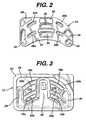
- the cover 14has a substantially flat panel 32 into which is formed a pair of gripping recesses 34, 36, two pairs of needle abutments 38a, 38b and 40a, 40b, and three end stops or point guards 42, 44, 46.
- the flat panel 32functions as a support member for end stops 42, 44, 46 and may be perforated to decrease material usage.
- the gripping recesses 34, 36are positioned and dimensioned to be received proximate the central recessed area 26 and are intended to accommodate the fingers and thumb of a user to aid in grasping and removing the cover 14 from a position covering the tray 12.
- the gripping recesses 34, 36may be disposed on the cover 14 in a position offset from the channels 16a, 16b, 18a, 18b.
- the gripping recessescan extend down further toward the central recessed surface area 26 without interfering with the needles stored in the package 10.
- the needle abutments 38a, 38b and 40a, 40bare aligned with the channels 16a, 16b and 18a, 18b, respectively, extending downward towards the channels 16a, 16b, 18a, 18b and any needles contained therein to a selected extent for the purpose of constraining the upward motion of any needles contained in the package 10 to a selected degree.
- End stop 42is shaped and positioned to be received proximate left recessed surface area 28 and end stops 44 and 46 are received proximate right recessed surface area 30 when the cover 14 is placed on the tray 12 after the needles have been loaded into the tray 12. When so placed, end stop 42 extends across channels 16a and 18a proximate left recessed surface area 28 and end stops 44 and 46 block channels 16b and 18b proximate right recessed surface area 30. The purpose of this juxtapositioning shall be explained below.
- Tray 12has a peripheral glue flange 54 for receiving a sealing membrane 60 (See FIG. 6 ) formed from aluminum, Tyvek or other conventional covering material used on blister packages which such sheet is adhered to the glue flange 54 by adhesive or plastic welding.
- An inner edge 56 of the glue flange 54defines an inner peripheral shape that approximates the outer peripheral shape of the cover 14.
- a peripheral sidewall 62extends between the recessed surface areas 26, 28, 30 to the inner edge 56 of glue flange 54.
- FIGS. 4 and 5illustrate a prior art needle package having a needle retainer B for holding a needle C.
- the needle Ccan be displaced from the retainer B and pierce the wall of the package A.
- FIGS. 6 and 7diagrammatically illustrate a portion of a needle package 10 in accordance with the present invention for holding a needle 58 and having a tray 12 with a recessed surface area 30.
- the needle 58is received in a channel 16b.
- a cover 14includes a needle abutment 38b for restraining the upward movement of the needle 58 and an end stop 44 which inserts into the recess 30.
- the tray 12 and cover 14are covered by a sealing membrane 60 adhered to glue flange 54, such that the sealing membrane 60 prevents the cover from lifting away from the tray and allowing the end stop 44 to escape from the recess 30.
- the end stop 44is held in front of the needle 58 despite there being some clearance between the cover 14, the tray 12 and the sealing membrane 60.
- the needleIn order for the needle to penetrate the tray 12, it must first penetrate the end stop 44 which is defined by descending and ascending walls 64, 66 respectively, an unlikely occurrence.
- FIG. 7depicts a tapered needle 68 in place of the straight needle 58 shown in FIG. 6 .
- the loose fit between the tray 12 and the cover 14permits the cover 14 to be easily withdrawn from the tray 12 to access the needle(s) contained therein. After the cover 14 is removed from the tray 12, the needle(s) contained therein can be easily removed by grasping them with the fingers since there is no frictional restraint to overcome. If desired, the tray 12 can be inverted over the sterile field to permit the needle(s) contained therein to be emptied from the tray 12 onto the sterile field.
Landscapes
- Health & Medical Sciences (AREA)
- Surgery (AREA)
- Life Sciences & Earth Sciences (AREA)
- Medical Informatics (AREA)
- Nuclear Medicine, Radiotherapy & Molecular Imaging (AREA)
- Engineering & Computer Science (AREA)
- Biomedical Technology (AREA)
- Heart & Thoracic Surgery (AREA)
- Dentistry (AREA)
- Molecular Biology (AREA)
- Animal Behavior & Ethology (AREA)
- General Health & Medical Sciences (AREA)
- Public Health (AREA)
- Veterinary Medicine (AREA)
- Packages (AREA)
- Infusion, Injection, And Reservoir Apparatuses (AREA)
Description
- The present invention relates to packages for sterile pointed objects, such as needles, and more particularly to thermoformed blister packages for such objects.
- Blister packs for needles are well known and used due to their effectiveness and economy. Pointed devices, such as needles, especially heavy ones, can puncture their packaging during shipping and handling. In the case of medical devices, punctures in the packaging renders them non-sterile and the sharply pointed devices can pose a safety hazard. In the past, this problem was attempted to be solved by incorporating snap-fit retainers or undercuts in the blister pack to establish an interference/friction fit to retain the pointed object in place within the pack and prevent punctures. In order to make the snap-fit retainers strong enough to hold needles in place within the pack, they must exert a strong grip on the needle which has to be overcome by the user when the needle is removed from the package. Because the use of snap-fit retainers requires a mechanical interaction between the package and the needle demanding close tolerances, a specific package has to be used with each different size needle. Due to the surface smoothness of the plastic material used in forming blister packs and the surface smoothness of needles, along with the high density of the needles, even a tight fit between the retainer and needle does not insure that the needle will not become dislodged given a sufficiently large shock in a critical direction. A known alternative technology is to use needle caps that are friction fit over the point of the needles before packaging to prevent the points from puncturing the packaging during shipping and handling. Protective caps, however, are difficult to remove and complicate time-critical surgical procedures.
- For example,
US 5772031 discloses a package including a cavity having a series of cavity slots transverse to the cavity's longitudinal axis. These slots permit a pair of stop plugs to be positioned to receive products of different lengths. Each stop plug has four lateral lugs for engaging the cavity slots to resist linear and rotational displacement of the stop plug. Each plug has bottom, end, and side walls to isolate the product end from the cavity. In addition a pair of fingers extending from the stop plug elastically grips the product to further restrain product movement. The fingers can flex to accommodate different sizes of products. A retainer snaps onto the cavity to close it. To complete the package assembly, a flexible covering is sealed to the top of the cavity. - The problems and disadvantage associated with the conventional techniques and devices utilized to hold pointed objects are overcome by the present invention as defied in claim 1, which includes a package having a tray portion with an internal hollow delimited by a bottom surface and a sidewall. The internal hollow receives the pointed object therein and a removable retaining member extends substantially parallel to the bottom surface over the internal hollow. A point guard depends from the support member towards the tray proximate the sidewall, with the point guard interposable between the sidewall, and a point on the pointed object to be held.
- For a better understanding of the present invention, reference is made to the following detailed description of an exemplary embodiment considered in conjunction with the accompanying drawings, in which:
FIG. 1 is an exploded view of a needle package in accordance with an exemplary embodiment of the present invention;FIG. 2 is a plan view of a cover portion of the needle package ofFIG. 1 ;FIG. 3 is a plan view of a tray portion of the needle package ofFIG. 1 ;FIGS. 4 and 5 are diagrammatic views of a needle package in accordance with the prior art; andFIGS. 6 and 7 are diagrammatic views of the needle package ofFIG. 1 .FIGS. 1-3 show aneedle package 10 which is preferably thermoformed or injection molded from plastic, such as polypropylene, polystyrene, polyethylene and equivalents thereof to yield a "blister" type package. Theneedle package 10 has atray portion 12 and acover 14. Thetray 12 has a plurality ofneedle channels needle channels channels areas recessed surface area 26 positioned between and below thechannels recessed surface area 28 is provided at one end of thechannels surface area 30 is provided at a distal end ofchannels - The
cover 14 has a substantiallyflat panel 32 into which is formed a pair ofgripping recesses needle abutments point guards flat panel 32 functions as a support member for end stops 42, 44, 46 and may be perforated to decrease material usage. Thegripping recesses recessed area 26 and are intended to accommodate the fingers and thumb of a user to aid in grasping and removing thecover 14 from a position covering thetray 12. Thegripping recesses cover 14 in a position offset from thechannels recessed surface area 26 without interfering with the needles stored in thepackage 10. Theneedle abutments channels channels package 10 to a selected degree.End stop 42 is shaped and positioned to be received proximate leftrecessed surface area 28 andend stops recessed surface area 30 when thecover 14 is placed on thetray 12 after the needles have been loaded into thetray 12. When so placed,end stop 42 extends acrosschannels recessed surface area 28 and end stops 44 and 46block channels surface area 30. The purpose of this juxtapositioning shall be explained below. - Tray 12 has a
peripheral glue flange 54 for receiving a sealing membrane 60 (SeeFIG. 6 ) formed from aluminum, Tyvek or other conventional covering material used on blister packages which such sheet is adhered to theglue flange 54 by adhesive or plastic welding. Aninner edge 56 of theglue flange 54 defines an inner peripheral shape that approximates the outer peripheral shape of thecover 14. Aperipheral sidewall 62 extends between therecessed surface areas inner edge 56 ofglue flange 54. FIGS. 4 and 5 illustrate a prior art needle package having a needle retainer B for holding a needle C. In transit or during handling, the needle C can be displaced from the retainer B and pierce the wall of the package A.FIGS. 6 and 7 diagrammatically illustrate a portion of aneedle package 10 in accordance with the present invention for holding aneedle 58 and having atray 12 with arecessed surface area 30. Theneedle 58 is received in achannel 16b. Acover 14 includes aneedle abutment 38b for restraining the upward movement of theneedle 58 and anend stop 44 which inserts into therecess 30. Thetray 12 andcover 14 are covered by asealing membrane 60 adhered toglue flange 54, such that thesealing membrane 60 prevents the cover from lifting away from the tray and allowing the end stop 44 to escape from therecess 30. In this manner, theend stop 44 is held in front of theneedle 58 despite there being some clearance between thecover 14, thetray 12 and thesealing membrane 60. In order for the needle to penetrate thetray 12, it must first penetrate theend stop 44 which is defined by descending and ascendingwalls FIG. 7 , the fact that there is some clearance between the components of thepackage 10, e.g., betweentray 12 andcover 14 and betweencover 14 and sealingmembrane 60 and because there is no requirement for an interference fit between theneedle 68 and thepackage 10, needles of various sizes and shapes can be accommodated therein.FIG. 7 depicts atapered needle 68 in place of thestraight needle 58 shown inFIG. 6 . The loose fit between thetray 12 and thecover 14 permits thecover 14 to be easily withdrawn from thetray 12 to access the needle(s) contained therein. After thecover 14 is removed from thetray 12, the needle(s) contained therein can be easily removed by grasping them with the fingers since there is no frictional restraint to overcome. If desired, thetray 12 can be inverted over the sterile field to permit the needle(s) contained therein to be emptied from thetray 12 onto the sterile field.- It should be understood that the embodiments described herein are merely exemplary and that a person skilled in the art may make many variations and modifications without departing from the scope of the invention as defined in the appended claims.
Claims (15)
- A package (10) for holding a pointed object (58; 68), comprising:(a) a tray portion (12) having an internal hollow delimited by a bottom surface and a sidewall, said internal hollow receiving the pointed object therein;(b) a removable retaining member (14) extending substantially parallel to said bottom sulfate over said internal hollow;(c) a point guard (44, 46) depending from said retaining member (14) towards said tray portion (12) proximate said sidewall, said point guard interposable between said sidewall and a point on the pointed object to be held; and(d) a cover sheet extending over said tray portion covering said internal hollow, said retaining member and said pointed object, said cover sheet being adapted for retaining said retaining member in a position wherein said point guard (44, 46) is interposed between said sidewall and said point of the pointed object:wherein an object supporting portion (16a, 16b; 18a, 18b) of said bottom surface is elevated above a remainder thereof, the pointed object (58; 68) being adapted to be supported upon said object supporting portion, said object supporting portion terminating at one end thereof in a descending wall that traverses from a level of said object supporting portion to a level of said remainder of said bottom surface, said point of the pointed object being positionable proximate said descending wall, said point guard (44, 46) extending parallel to said descending wall towards said remainder of said bottom surface to a level below said object supporting portion.
- The package of Claim 1, wherein said descending wall, said remainder of said bottom surface and said sidewall define a first depressed area in said tray portion (12) disposed proximate a first end of said object supporting portion and said point guard (44, 46) has a complementary shape to said first depressed area, such that said point guard inserts within said first depressed area.
- The package of Claim 2, wherein said point guard (44, 46) has a first wall section (64) disposed proximate said object supporting portion and a second wall section (66) disposed proximate said sidewall, said first wall section and said second wall section having a spacing therebetween, such that said point of the pointed object (58) would penetrate said first wall section and said second wall section before penetrating said sidewall.
- The package of Claim 3, wherein said retaining member (14) has a generally planar portion from which said point guard (44, 46) depends, said planar portion and said point guard covering said hollow.
- The package of Claim 4, wherein the pointed object (58; 68) further has at least a second point, and said package further comprises a second point guard (42) being adapted to be positioned proximate said second point of the pointed object.
- The package of Claim 5, wherein said tray portion (12) further has a second depressed area accommodating the second point guard (42).
- The package of Claim 6, the tray portion (12) further comprising a third depressed area (26) located toward a center of said object supporting portion, said third depressed area facilitating grasping the pointed object (58; 68) held within said package, said object supporting portion holding the object above a bottom surface of said third depressed area.
- The package of Claim 5, wherein said object supporting portion is in the form of a channel having a U-shaped cross-section.
- The package of Claim 8, wherein said channel is curved to accommodate a curved needle.
- The package of Claim 8. wherein said object supporting portion includes a plurality of channels with a U-shaped cross section, each of said channels being adapted to accommodate at least one pointed object.
- The package of Claim 1, wherein a clearance exists botween said tray portion (12), said retaining member (14) and said point guard (44, 46), such that a range of differently dimensioned pointed objects can be contained in said package.
- The package of Claim 1, wherein said retaining member (14) has object restraint projections projecting downwards in the same general direction as said point guard (44, 46), said object restraint projections protruding into said channel to constrain the motion of the pointed object (58; 68) contained therein.
- The package of Claim 1, wherein said tray portion (12) has a peripheral ledge to accommodate said retaining member (14), said retaining member having a peripheral shape that is complementary to the peripheral shape of said tray portion.
- The package of Claim 1, wherein said tray portion (12) is of a thermoformed blister-type construction.
- The package of Claim 14, wherein said retaining member (14) and said point guard (44, 46 are of thermoformed blister-type construction.
Applications Claiming Priority (3)
| Application Number | Priority Date | Filing Date | Title |
|---|---|---|---|
| US676861 | 1996-07-03 | ||
| US09/676,861US6394269B1 (en) | 2000-09-29 | 2000-09-29 | Needle package with point guards |
| PCT/US2001/019434WO2002028288A1 (en) | 2000-09-29 | 2001-06-18 | Needle package with point guards |
Publications (3)
| Publication Number | Publication Date |
|---|---|
| EP1320328A1 EP1320328A1 (en) | 2003-06-25 |
| EP1320328A4 EP1320328A4 (en) | 2007-06-06 |
| EP1320328B1true EP1320328B1 (en) | 2009-09-09 |
Family
ID=24716325
Family Applications (1)
| Application Number | Title | Priority Date | Filing Date |
|---|---|---|---|
| EP01944601AExpired - LifetimeEP1320328B1 (en) | 2000-09-29 | 2001-06-18 | Needle package with point guards |
Country Status (5)
| Country | Link |
|---|---|
| US (1) | US6394269B1 (en) |
| EP (1) | EP1320328B1 (en) |
| AU (1) | AU2001266994A1 (en) |
| DE (1) | DE60139885D1 (en) |
| WO (1) | WO2002028288A1 (en) |
Families Citing this family (19)
| Publication number | Priority date | Publication date | Assignee | Title |
|---|---|---|---|---|
| US6915901B2 (en) | 2000-12-11 | 2005-07-12 | Marc Feinberg | Packaging assembly for surgical use |
| US20020191938A1 (en)* | 2001-06-13 | 2002-12-19 | Ethicon Endo-Surgery, Inc. | Fiberoptic coil tray and carrier package |
| US6691868B2 (en)* | 2001-12-31 | 2004-02-17 | Ethicon, Inc. | Kit package for multiple small devices |
| US6793078B2 (en) | 2001-12-31 | 2004-09-21 | Ethicon, Inc. | Blister tray with a blister card |
| US6814236B2 (en)* | 2001-12-31 | 2004-11-09 | Ethicon, Inc. | Blister tray with a package for a small device |
| US8746445B2 (en)* | 2003-07-18 | 2014-06-10 | Covidien Lp | Suture packaging |
| US7637369B2 (en)* | 2003-07-18 | 2009-12-29 | Tyco Healthcare Group Lp | Suture packaging |
| US7520382B2 (en) | 2003-07-18 | 2009-04-21 | Tyco Healthcare Group Lp | Suture packaging |
| US7104401B2 (en)* | 2003-11-12 | 2006-09-12 | Ethicon, Inc. | Packaging assembly for surgical instruments |
| US20050269231A1 (en)* | 2004-06-08 | 2005-12-08 | Jack White | Container for packaging and deploying devices |
| US9364215B2 (en)* | 2006-01-26 | 2016-06-14 | Covidien Lp | Medical device package |
| US20090209031A1 (en)* | 2006-01-26 | 2009-08-20 | Tyco Healthcare Group Lp | Medical device package |
| US20070170080A1 (en)* | 2006-01-26 | 2007-07-26 | Joshua Stopek | Medical device package |
| WO2007143863A1 (en)* | 2006-06-13 | 2007-12-21 | F. Hoffmann-La Roche Ag | Sterile packaging for a medical article |
| CA2604433A1 (en)* | 2006-10-06 | 2008-04-06 | Tyco Healthcare Group Lp | Medical device package including self-puncturable port |
| US20080171972A1 (en) | 2006-10-06 | 2008-07-17 | Stopek Joshua B | Medical device package |
| US10342650B2 (en) | 2013-09-27 | 2019-07-09 | Covidien Lp | Skirted hernia repair device |
| US20180206842A1 (en)* | 2014-07-21 | 2018-07-26 | Surgical Specialities Corporation | Suture carrier devices, systems and methods of using same |
| US11751986B2 (en)* | 2019-01-04 | 2023-09-12 | Cook Medical Technologies Llc | Packaging system for ureteral stent |
Family Cites Families (15)
| Publication number | Priority date | Publication date | Assignee | Title |
|---|---|---|---|---|
| US3951263A (en)* | 1972-05-20 | 1976-04-20 | Abel Morrall Limited | Holders for needles, pins and like articles |
| US3951261A (en) | 1974-08-28 | 1976-04-20 | Ethicon, Inc. | Needled suture mounting and dispensing device and package |
| US4424898A (en)* | 1982-04-08 | 1984-01-10 | Ethicon, Inc. | Needle and suture holder and package |
| US4619364A (en) | 1982-09-13 | 1986-10-28 | The Stanley Works | Display package for drill bits and the like |
| US5099994A (en)* | 1988-08-24 | 1992-03-31 | Ethicon, Inc. | Oval wrap suture package |
| US5024323A (en)* | 1989-09-25 | 1991-06-18 | Bernard Bolton | Suture extender and needle guard |
| CA2080978A1 (en) | 1992-01-02 | 1993-07-03 | Hans-Jurgen F. Sinn | Retainer for a combined surgical needle shield with a needle tip stop feature |
| US5322163A (en) | 1993-06-09 | 1994-06-21 | Plastofilm Industries, Inc. | Catheter tray package with lockable insert |
| US5617952A (en)* | 1993-12-07 | 1997-04-08 | Kranendonk; Donald H. | Suture needle protector |
| DE69503818T2 (en) | 1994-04-04 | 1999-03-04 | Ethicon, Inc., Somerville, N.J. | Suture packaging and method for wrapping the suture in the packaging |
| US5575382A (en)* | 1994-12-22 | 1996-11-19 | Ethicon, Inc. | Rotary self-winding two-piece ligature package |
| US5675961A (en)* | 1995-06-06 | 1997-10-14 | Ethicon, Inc. | Suture dispenser |
| US5628395A (en)* | 1995-06-23 | 1997-05-13 | Ethicon, Inc. | Suture tray package having grooved winding surface |
| US5772031A (en)* | 1996-02-15 | 1998-06-30 | Zimmer, Inc. | Package for an elongated medical product |
| EP0800789A1 (en) | 1996-04-10 | 1997-10-15 | Ethicon, Inc. | Package for suture anchor assembly |
- 2000
- 2000-09-29USUS09/676,861patent/US6394269B1/ennot_activeExpired - Lifetime
- 2001
- 2001-06-18DEDE60139885Tpatent/DE60139885D1/ennot_activeExpired - Lifetime
- 2001-06-18WOPCT/US2001/019434patent/WO2002028288A1/enactiveApplication Filing
- 2001-06-18EPEP01944601Apatent/EP1320328B1/ennot_activeExpired - Lifetime
- 2001-06-18AUAU2001266994Apatent/AU2001266994A1/ennot_activeAbandoned
Also Published As
| Publication number | Publication date |
|---|---|
| EP1320328A4 (en) | 2007-06-06 |
| WO2002028288A1 (en) | 2002-04-11 |
| EP1320328A1 (en) | 2003-06-25 |
| US6394269B1 (en) | 2002-05-28 |
| DE60139885D1 (en) | 2009-10-22 |
| AU2001266994A1 (en) | 2002-04-15 |
Similar Documents
| Publication | Publication Date | Title |
|---|---|---|
| EP1320328B1 (en) | Needle package with point guards | |
| EP0648686A1 (en) | Sterile packaging | |
| EP0048741B1 (en) | Moisture impervious means for unit dose packaging | |
| US4324331A (en) | Packaging for surgical implements | |
| US5772031A (en) | Package for an elongated medical product | |
| EP0091792B1 (en) | Needle and suture holder and package | |
| US3853217A (en) | Pipette tip package | |
| EP2699482B1 (en) | Packaging for medical containers | |
| US5944191A (en) | Peelable entry-resistant package | |
| JP5591811B2 (en) | cover | |
| EP0575193B1 (en) | Multi-strand suture package and cover-latching element | |
| RU2016122047A (en) | MULTICOMPONENT PACKAGES FOR MEDICAL DEVICES | |
| US20090230130A1 (en) | System for storing and unpacking encased article | |
| EP1581131B1 (en) | Sharps disposal container | |
| US4438845A (en) | Control package for elongated article | |
| KR20180132108A (en) | Containment sleeve for packages containing medical devices | |
| EP0263243A2 (en) | Package assembly for an article | |
| EP4442596B1 (en) | A packaged contact lens | |
| EP1813538A2 (en) | Cartridge accomodating case | |
| EP4019421B1 (en) | A spacer structure for separating two stacked tubs configured for the storage and/or transport of a plurality of medical containers, and a packaging including said spacer | |
| JPH057182Y2 (en) | ||
| OA20511A (en) | Child-resistant packaging | |
| AU1474202A (en) | Improvements in, or relating to blister packaging | |
| JP2003219778A (en) | Water container for smoking agent | |
| JPH0667365U (en) | Container gathering tray |
Legal Events
| Date | Code | Title | Description |
|---|---|---|---|
| PUAI | Public reference made under article 153(3) epc to a published international application that has entered the european phase | Free format text:ORIGINAL CODE: 0009012 | |
| 17P | Request for examination filed | Effective date:20030331 | |
| AK | Designated contracting states | Designated state(s):AT BE CH CY DE DK ES FI FR GB GR IE IT LI LU MC NL PT SE TR | |
| AX | Request for extension of the european patent | Extension state:AL LT LV MK RO SI | |
| RBV | Designated contracting states (corrected) | Designated state(s):DE FR GB IT | |
| A4 | Supplementary search report drawn up and despatched | Effective date:20070507 | |
| 17Q | First examination report despatched | Effective date:20071011 | |
| GRAP | Despatch of communication of intention to grant a patent | Free format text:ORIGINAL CODE: EPIDOSNIGR1 | |
| RTI1 | Title (correction) | Free format text:NEEDLE PACKAGE WITH POINT GUARDS | |
| GRAS | Grant fee paid | Free format text:ORIGINAL CODE: EPIDOSNIGR3 | |
| GRAA | (expected) grant | Free format text:ORIGINAL CODE: 0009210 | |
| AK | Designated contracting states | Kind code of ref document:B1 Designated state(s):DE FR GB IT | |
| REG | Reference to a national code | Ref country code:GB Ref legal event code:FG4D | |
| REF | Corresponds to: | Ref document number:60139885 Country of ref document:DE Date of ref document:20091022 Kind code of ref document:P | |
| PLBE | No opposition filed within time limit | Free format text:ORIGINAL CODE: 0009261 | |
| STAA | Information on the status of an ep patent application or granted ep patent | Free format text:STATUS: NO OPPOSITION FILED WITHIN TIME LIMIT | |
| 26N | No opposition filed | Effective date:20100610 | |
| REG | Reference to a national code | Ref country code:FR Ref legal event code:PLFP Year of fee payment:16 | |
| REG | Reference to a national code | Ref country code:FR Ref legal event code:PLFP Year of fee payment:17 | |
| REG | Reference to a national code | Ref country code:FR Ref legal event code:PLFP Year of fee payment:18 | |
| PGFP | Annual fee paid to national office [announced via postgrant information from national office to epo] | Ref country code:FR Payment date:20200512 Year of fee payment:20 Ref country code:DE Payment date:20200602 Year of fee payment:20 | |
| PGFP | Annual fee paid to national office [announced via postgrant information from national office to epo] | Ref country code:GB Payment date:20200610 Year of fee payment:20 Ref country code:IT Payment date:20200512 Year of fee payment:20 | |
| REG | Reference to a national code | Ref country code:DE Ref legal event code:R071 Ref document number:60139885 Country of ref document:DE | |
| REG | Reference to a national code | Ref country code:GB Ref legal event code:PE20 Expiry date:20210617 | |
| PG25 | Lapsed in a contracting state [announced via postgrant information from national office to epo] | Ref country code:GB Free format text:LAPSE BECAUSE OF EXPIRATION OF PROTECTION Effective date:20210617 |