EP1317909B1 - Adjustable introducer valve - Google Patents
Adjustable introducer valveDownload PDFInfo
- Publication number
- EP1317909B1 EP1317909B1EP03004935AEP03004935AEP1317909B1EP 1317909 B1EP1317909 B1EP 1317909B1EP 03004935 AEP03004935 AEP 03004935AEP 03004935 AEP03004935 AEP 03004935AEP 1317909 B1EP1317909 B1EP 1317909B1
- Authority
- EP
- European Patent Office
- Prior art keywords
- valve
- membrane
- aperture
- instrument
- diameter
- Prior art date
- Legal status (The legal status is an assumption and is not a legal conclusion. Google has not performed a legal analysis and makes no representation as to the accuracy of the status listed.)
- Expired - Lifetime
Links
- 239000012528membraneSubstances0.000claimsdescription84
- 230000004044responseEffects0.000claimsdescription6
- 231100000435percutaneous penetrationToxicity0.000claimsdescription4
- 239000013536elastomeric materialSubstances0.000claimsdescription3
- 239000012530fluidSubstances0.000description23
- 238000001356surgical procedureMethods0.000description11
- 239000007789gasSubstances0.000description9
- 238000000034methodMethods0.000description9
- 238000007789sealingMethods0.000description9
- 230000007246mechanismEffects0.000description6
- 230000008859changeEffects0.000description5
- 210000001015abdomenAnatomy0.000description3
- 230000002401inhibitory effectEffects0.000description3
- 208000014674injuryDiseases0.000description3
- 239000000463materialSubstances0.000description3
- 230000000149penetrating effectEffects0.000description3
- 230000002093peripheral effectEffects0.000description3
- CURLTUGMZLYLDI-UHFFFAOYSA-NCarbon dioxideChemical compoundO=C=OCURLTUGMZLYLDI-UHFFFAOYSA-N0.000description2
- JOYRKODLDBILNP-UHFFFAOYSA-NEthyl urethaneChemical compoundCCOC(N)=OJOYRKODLDBILNP-UHFFFAOYSA-N0.000description2
- 230000003187abdominal effectEffects0.000description2
- 210000001124body fluidAnatomy0.000description2
- 238000013461designMethods0.000description2
- 230000002262irrigationEffects0.000description2
- 238000003973irrigationMethods0.000description2
- 238000002357laparoscopic surgeryMethods0.000description2
- 238000002324minimally invasive surgeryMethods0.000description2
- 230000035515penetrationEffects0.000description2
- 229920001296polysiloxanePolymers0.000description2
- 230000009467reductionEffects0.000description2
- 230000008733traumaEffects0.000description2
- 238000013022ventingMethods0.000description2
- IJGRMHOSHXDMSA-UHFFFAOYSA-NAtomic nitrogenChemical compoundN#NIJGRMHOSHXDMSA-UHFFFAOYSA-N0.000description1
- 208000027418Wounds and injuryDiseases0.000description1
- 210000000683abdominal cavityAnatomy0.000description1
- 210000003815abdominal wallAnatomy0.000description1
- 230000004308accommodationEffects0.000description1
- 238000013459approachMethods0.000description1
- 230000015572biosynthetic processEffects0.000description1
- 239000010839body fluidSubstances0.000description1
- 229910002092carbon dioxideInorganic materials0.000description1
- 239000001569carbon dioxideSubstances0.000description1
- 230000000295complement effectEffects0.000description1
- 230000006378damageEffects0.000description1
- UREBDLICKHMUKA-CXSFZGCWSA-NdexamethasoneChemical compoundC1CC2=CC(=O)C=C[C@]2(C)[C@]2(F)[C@@H]1[C@@H]1C[C@@H](C)[C@@](C(=O)CO)(O)[C@@]1(C)C[C@@H]2OUREBDLICKHMUKA-CXSFZGCWSA-N0.000description1
- 230000010339dilationEffects0.000description1
- 229910001873dinitrogenInorganic materials0.000description1
- 238000001647drug administrationMethods0.000description1
- 238000003780insertionMethods0.000description1
- 230000037431insertionEffects0.000description1
- 238000012978minimally invasive surgical procedureMethods0.000description1
- 238000012986modificationMethods0.000description1
- 230000004048modificationEffects0.000description1
- 230000010412perfusionEffects0.000description1
- 239000012858resilient materialSubstances0.000description1
- 230000000717retained effectEffects0.000description1
- 238000013519translationMethods0.000description1
Images


Classifications
- A—HUMAN NECESSITIES
- A61—MEDICAL OR VETERINARY SCIENCE; HYGIENE
- A61B—DIAGNOSIS; SURGERY; IDENTIFICATION
- A61B17/00—Surgical instruments, devices or methods
- A61B17/34—Trocars; Puncturing needles
- A61B17/3462—Trocars; Puncturing needles with means for changing the diameter or the orientation of the entrance port of the cannula, e.g. for use with different-sized instruments, reduction ports, adapter seals
- A—HUMAN NECESSITIES
- A61—MEDICAL OR VETERINARY SCIENCE; HYGIENE
- A61B—DIAGNOSIS; SURGERY; IDENTIFICATION
- A61B17/00—Surgical instruments, devices or methods
- A61B17/34—Trocars; Puncturing needles
- A61B17/3498—Valves therefor, e.g. flapper valves, slide valves
- A—HUMAN NECESSITIES
- A61—MEDICAL OR VETERINARY SCIENCE; HYGIENE
- A61B—DIAGNOSIS; SURGERY; IDENTIFICATION
- A61B17/00—Surgical instruments, devices or methods
- A61B17/34—Trocars; Puncturing needles
- A61B17/3462—Trocars; Puncturing needles with means for changing the diameter or the orientation of the entrance port of the cannula, e.g. for use with different-sized instruments, reduction ports, adapter seals
- A61B2017/3464—Trocars; Puncturing needles with means for changing the diameter or the orientation of the entrance port of the cannula, e.g. for use with different-sized instruments, reduction ports, adapter seals with means acting on inner surface of valve or seal for expanding or protecting, e.g. inner pivoting fingers
- A—HUMAN NECESSITIES
- A61—MEDICAL OR VETERINARY SCIENCE; HYGIENE
- A61B—DIAGNOSIS; SURGERY; IDENTIFICATION
- A61B17/00—Surgical instruments, devices or methods
- A61B17/34—Trocars; Puncturing needles
- A61B2017/347—Locking means, e.g. for locking instrument in cannula
Definitions
- the present inventionrelates generally to apparatus for providing percutaneous access to an internal operative site during a surgical procedure. More particularly, the present invention relates to an adjustable valve according to the preamble of claim 1 for accommodating viewing scopes and instruments having a wide variety of cross-sectional shapes and sizes, and to an introducer assembly as defined in claim 9.
- Minimally invasive surgical proceduresare typically performed by penetrating the patient's skin with small-diameter access tubes, usually referred to as trocars, and opening the trocars within a patient's body cavity.
- a viewing scopeis introduced through one such trocar and the surgeon operates using instruments introduced through other appropriately placed trocars while viewing the operative site on a video monitor connected to the viewing scope.
- Minimally invasive or endoscopic proceduresgenerally require sealing of the instruments inserted into the body, i.e., provisions must be made to ensure that fluids do not enter or exit the body through the endoscopic incision.
- Trocars used in laparoscopic proceduresgenerally include a valve at their proximal end to allow passage of the scope or surgical instrument while inhibiting leakage of the insufflating gas or other body fluids.
- trocar valvesThe design of suitable trocar valves involves specialized considerations, particularly the design of trocar valves used in laparoscopic procedures in a pressurized environment.
- the trocar valves used in these proceduresshould be readily sealable to inhibit the leakage of gas and other fluids from the abdomen or other body cavities.
- Trocar valveshave been designed with inner seals that can accommodate various sized instruments.
- these sealscomprise a one-way elastomeric member(s) that allows instruments to pass through, while inhibiting fluid leakage between the instrument shaft and the seal.
- one such elastomeric membercomprises an elastomeric plug having crossed slits designed to allow instruments to pass through the slits in the distal direction. Endoscopic instruments are introduced from the proximal end of the trocar through the crossed slits, forcing the elastomeric member to open and allow passage of the instrument to the percutaneous incision. The elastomeric plug is biased against the instrument periphery to create a fluid seal.
- the one-way elastomeric seals described abovehave a number of drawbacks.
- these types of sealstypically do not assume a shape that corresponds with the instrument's cross-sectional shape (usually circular) after the instrument has penetrated through the seal. Accordingly, fluid pressure within the body cavity may cause leakage of gases or other bodily fluids between the elastomeric seal and the instrument.
- Another drawback with these types of sealsis that the bias force applied to the instrument by the seal creates frictional resistance to movement of the instrument, which makes it more difficult for the surgeon to manipulate the instrument within the patient's body.
- larger diameter instrumentstend to force the elastomeric seal radially outward further than smaller diameter instruments, thereby increasing the bias force against these instruments. The increased bias force leads to increased friction, making it even more difficult for the surgeon to manipulate larger diameter instruments during the surgical procedure.
- the cannula shafttypically has an axial lumen with a diameter at least as large as the largest instrument that will pass therethrough (i.e., typically around 10-12 mm).
- a diameter at least as large as the largest instrument that will pass therethroughi.e., typically around 10-12 mm.
- these instrumentswill pivot or move transversely within this lumen. Pivotal or transverse movement of the instrument causes lateral pressure to be applied against the elastomeric seal within the trocar valve. This lateral pressure against the seal may allow gases or other fluids to leak between the seal and the opposite side of the instrument shaft.
- trocars suitable for use in laparoscopic and other minimally invasive procedureswhich can accommodate a wide variety of instrument sizes. It would be desirable if these trocars incorporated adjustable seals designed to accommodate various sized instruments and to assume a shape generally corresponding with the cross-sectional shape of the instruments passing therethrough to facilitate the formation of a fluid-tight seal around the instrument periphery.
- the adjustable sealsshould be designed to minimize the frictional resistance against instruments passing therethrough to facilitate manipulation of the instruments within the patient's body by the surgeon. Further, it would be desirable to reduce or eliminate lateral pressure applied against the trocar seal by instruments pivoting or otherwise moving within the trocar shaft to thereby minimize fluid leakage through the trocar valve.
- U.S. Patent Nos. 5,354,280, 5,385,552 and 5,391,153 to Haberdescribe trocars having seals for accommodating various sized instruments.
- the sealscomprise a plurality of elastomeric elements biased toward each other within the trocar shaft. The seals are arranged so that pressure from the proximal end will force the seals open to allow instruments to pass through.
- U.S. Patent Nos. 5,338,313 and 5,167,636describe trocar valves with radially compressible sealing bodies for receiving various sized instruments.
- U.S. Patent No. 5,304,143 to Greenteaches a valve assembly comprising first and second valves for allowing the passage of instruments therethrough.
- the first valvecomprises a resilient material configured to engage the outer surface of the instrument in a fluid tight manner.
- the second valveincludes a pair of manually operated clamps for opening and closing the second valve.
- U.S. Patent No. 5,127,626 to Hilaldescribes a trocar valve having spring biased cams for radially compressing sealing members into sealing engagement with instruments extending through an axial passage of the trocar.
- U.S. Patent Nos. 5,407,433 and 5,407,433 to Loomasdescribe a gas-tight seal for accomodating surgical instruments with varying diameters. The seal can be moved laterally in response to lateral movement of the instrument.
- U.S. Patent No. 5,397,335 to Gresldiscloses a trocar assembly having removable adapter seals for accomodating instruments of various sizes.
- a valve according to the preamble of claim 1is known from WO-A-94/07 552.
- the present inventionprovides apparatus for providing percutaneous access to an internal operative site during a surgical procedure.
- the inventionprovides an adjustable pnemostasis valve for providing a fluid seal around the periphery of endoscopic viewing scopes and instruments having a wide variety of cross-sectional sizes.
- the valvecomprises a first valve member having an opening for receiving an elongated object, such as an insufflation needle, obturator, viewing scope or an endoscopic instrument, and a flexible membrane defining an aperture substantially aligned with the opening in the first valve member.
- a second valve memberis coupled to the flexible membrane for moving the membrane relative to the first valve member. As the membrane is moved by the second valve member, the size of the aperture varies so that the membrane can accommodate various sized instruments.
- the flexible membraneis constructed of a resilient, elastomeric material suitable for sealing various sized instruments, such as urethane, rubber, silicone or the like. Movement of the second valve member either stretches or relaxes the membrane to thereby change the size of the aperture.
- the membranehas an annular shape with an outer peripheral edge and an inner portion that defines a circular, central aperture for accommodating cylindrical instruments. Movement of the second valve member stretches or relaxes the outer peripheral edge of the membrane, thereby enlarging or reducing the size, i.e., cross-sectional area, of the aperture.
- the membrane aperturewill generally retain its circular shape when the area of the aperture varies so that the membrane conforms to the cylindrical instruments passing therethrough. This helps to minimize fluid leakage between the membrane and the instruments.
- the membraneis configured to naturally provide a gas-tight seal around the periphery of instruments (i.e., the membrane is not directly biased against the outer surface of the instrument).
- the membranewill be suitably stretched or relaxed by the second valve member so that the aperture has a diameter slightly less than the outer diameter of the instrument passing therethrough to provide a gas seal against the instrument.
- the aperture diameterwill only be slightly less than the instrument diameter, (e.g., on the order of about 0.1 to 0.2 mm) to minimize frictional resistance between the instrument and the membrane, thereby facilitating manipulation of the instrument by the surgeon.
- the membranewill apply substantially the same amount of inward force against smaller and larger sized instruments. Therefore, the frictional resistance between the instruments and the membrane will be substantially the same for different sized instruments so that the surgeon does not encounter different degrees of friction for each instrument during surgical procedures.
- the second valve memberis a collar threadably coupled to the outer surface of a hollow tube (the first valve member) having a proximal opening for receiving viewing scopes, instruments and the like.
- the outer edge of the membraneis attached to the collar, and the inner portion of the membrane stretches over the top of the hollow tube to cover a portion of the proximal opening.
- Rotation of the collaraxially moves the collar and the outer edge of the membrane relative to the hollow tube to either stretch or relax the inner portion of the membrane.
- the surgeonrotates the collar so that the collar and the outer edge of the membrane move distally relative to the hollow tube. This stretches the inner portion of the membrane radially outward from the center of the proximal opening, thereby enlarging the aperture to receive larger instruments.
- rotating the collar in the opposite directionwill reduce the size of the aperture for receiving smaller instruments.
- the valveis attached to the proximal end of a cannula shaft to form part of an introducer assembly, such as a trocar or a radially expandable introducer, for introducing instruments and viewing scopes through a percutaneous penetration into a patient's body.
- the valvemay further include an alignment mechanism that inhibits non-axial (transverse) movement of the instruments relative to the membrane during insertion and manipulation of the instruments by the surgeon. Transversely securing the instruments to the membrane reduces the lateral pressure that may be applied by the instruments against the membrane when these instruments are pivoted or otherwise moved transversely within the cannula shaft. Reduction of the lateral pressure minimizes leakage through the valve during the surgical procedure.
- the valveis particularly useful in combination with radially expandable dilation devices, such as those described in U.S. Patent No. 5,431,676.
- the valvemay also be useful with devices available under the STEPTM Cannula and Obturator with Radially Expandable Sleeve tradename from Innerdyne Medical, Sunnyvale California 94089.
- the valveis pivotally coupled to the cannula shaft so that the membrane will rotate in response to rotation of an instrument extending through the shaft.
- the valveis gimballed to the cannula shaft for rotation in any direction about a plane transverse to the shaft axis. This allows the valve to rotate in any direction about the shaft in response to pivotal movement of the instrument relative to the shaft. Consequently, the valve will pivot with the instrument to minimize lateral pressure applied by the instrument against the membrane.
- the valvefurther includes means for securing a proximal portion of the instrument at or near the center of the membrane.
- the securing meanscomprises one or more holding members coupled to the first valve member for preventing transverse movement of the instrument relative to the membrane, while allowing axial movement.
- the holding membersare configured to moved radially inward and outward to accommodate various sized instruments.
- the present inventionis useful for introducing elongate objects through percutaneous penetrations into a variety of target locations within a patient's body for a variety of purposes.
- Such purposesinclude drainage, intra-organ drug administration, feeding, perfusion, aspiration, and the like, most usually being the introduction of viewing scopes and surgical instruments for use in minimally invasive procedures, such as laparoscopy, thoracoscopy, arthroscopy and the like.
- the valve assembly of the present inventionwill typically be used in conjunction with an introducer assembly, such as a trocar or a radially expandable introducer, for providing percutaneous access to an internal operative site during a surgical procedure.
- the introducerincludes an elongate cannula having an axial lumen for delivering instruments and viewing scopes through a port, and an obturator, which is initially present in the cannula and which facilitates penetration of the cannula through the patient's skin. After penetrating the patient's skin, the obturator is removed to provide a port for access into a body cavity.
- the length of the cannulawill vary depending on the intended usage, but will generally be in the range of 10 cm to 25 cm. For laparoscopic procedures, the length will usually be in the range of about 10 to 20 cm, typically being in the range of about 10 cm to 15 cm. For thoracoscopic procedures, the length will generally be shorter, typically having a length in the range of 5 to 10 cm.
- the introducerwill usually include a handle or cannula hub coupled to the proximal end of the cannula for facilitating manipulation of the cannula by the surgeon.
- the handleusually includes an inner cavity fluidly coupled to the axial lumen of the cannula and a port for introducing or venting insufflation gas, irrigation, aspiration and the like, to and from the patient's body.
- the valve assembly of the present inventionis coupled to or incorporated within the handle for sealingly receiving instruments passing through the cannula shaft and into the patient.
- the present inventionwill find particular use with radially expandable introducers, such as the STEPTM introducer from Innerdyne Medial, Sunnyvale, California 94089, as well was with conventional trocars commercially available from suppliers such as United States Surgical Corp., Norwalk, Conn.; Endomed division of Cooper Surgical Inc., Shelton, Conn.; and Dexide, Inc., Fort Worth, Tex.
- radially expandable introducerssuch as the STEPTM introducer from Innerdyne Medial, Sunnyvale, California 94089
- the valve assembly of the present inventiongenerally includes first and second valve members and a flexible membrane.
- the first and second valve membersare movable relative to each other to change the shape of the membrane to provide a peripheral seal about instruments and viewing scopes having a wide variety of cross-sectional shapes and diameters.
- the valve memberscan be moved manually by the surgeon or the valve assembly may include an actuator and a drive mechanism for automatically moving the valve members.
- the valve memberswill be configured to move between discrete settings, with each setting corresponding to a different sized instrument, such as a 5 mm or 12 mm diameter instrument.
- the valve assemblymay further include means for displaying the instrument setting to the surgeon.
- the flexible membraneis constructed of a resilient elastomeric material which is sufficiently resilient to accommodate and provide a fluid seal against the periphery of instruments of varying diameters.
- the membranemay comprise a variety of shapes, but is preferably a thin, annular membrane having a central, circular aperture for receiving substantially cylindrical instruments.
- the membranewill be capable of being stretched radially outward so that the diameter of the central aperture can be enlarged at least 1.5 to 4 times its original diameter.
- the valve membersare configured to symmetrically stretch the outer edge of the membrane so that the central aperture substantially maintains a circular shape in the enlarged configurations, which minimizes fluid leakage through the membrane.
- the membranecan have an aperture with a shape other than circular, such as square, rectangular, C-shaped, etc., to accommodate instruments or scopes having shapes other than cylindrical.
- Membraneis constructed of a material that will generally retain its sealing properties after being stretched and then relaxed back into its natural configuration. Suitable materials for the membrane are silicone, rubber, urethane and the like.
- the membraneis suitably coupled to the first and second valve members so that it will provide a gas-tight seal around the periphery of an instrument passing through the aperture.
- This sealwill preferably result from the aperture having a slightly smaller inner diameter than the outer diameter of the instrument.
- the difference in diameterswill preferably be large enough to create a suitable gas seal and small enough to minimize friction between the instrument and the membrane.
- the aperturewill usually have an inner diameter of about 0.1 to 3.0 mm less than the outer diameter of the instrument passing therethrough.
- the instrumentswill typically have diameters ranging from about 5 mm to about 12 mm. Accordingly, the valve members will be configured to stretch or relax the membrane so that the aperture has a diameter from about 2.5 mm to 9.0 mm.
- the valve assembly of the present inventionwill preferably include an alignment mechanism for preventing or at least inhibiting non-axial or transverse movement of instruments relative to the membrane. This reduces the lateral pressure that may be applied by the objects against the membrane when these objects are pivoted or otherwise moved relative to the valve and the cannula shaft. Reduction of the lateral pressure minimizes leakage through the valve during the surgical procedure.
- the alignment mechanismcomprises a device for pivoting the valve assembly relative to the handle of the introducer in response to pivotal movement of the instrument shaft. In this manner, the valve assembly will move with the instrument so that the instrument does not apply lateral pressure against a portion of the membrane when the instrument is manipulated or otherwise pivoted relative to the cannula.
- valve assemblyis fixed to the handle and the alignment mechanism comprises means for securing the instrument at or near the center of the membrane, such as a plurality of elongate holding members.
- the holding memberspreferably extend radially inward to define a central gap at the membrane center for receiving the instruments. In this configuration, the holding members are capable of being pivoted or otherwise moved to change the size of the central gap for various sized instruments.
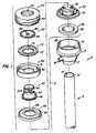
- introducer assembly 2generally includes an elongate shaft or cannula 4, a handle 6 and a valve assembly 8.
- Cannula 4has a proximal end 10, a distal end (not shown) and an axial lumen 14 therebetween for receiving elongate objects, such as an endoscope and/or surgical instruments for performing a surgical procedure within the patient's body.
- Introducer assembly 2will also include access device(s) for penetrating the patient's skin and providing a port for access into a body cavity, such as an obturator (not shown), an insufflation needle and/or a mechanism for radially expanding a penetration in the patient's skin.
- the access device(s)can be used to introduce or withdraw fluids, particularly being used for performing the initial stages of insufflation.
- One suitable access device for use with the present inventionis described in commonly assigned U.S. Patent No. 5,431,676 to Dubrul et al..
- handle 6includes a distal hub 7 attached to proximal end 10 of cannula 4.
- Handle 6defines an inner cavity 16 for housing a portion of valve assembly 8 and for permitting passage of the access device(s), an endoscope and/or surgical instruments through handle 6 to axial lumen 14 of cannula 4.
- Handle 6includes a port or stopcock 18 extending radially outward from cavity 16 for permitting introduction or venting of insufflation gas, irrigation, aspiration and the like.
- Valve assembly 8generally comprises a pivot base 30 disposed within cavity 16 of handle 6, and a first valve member or pivot tower 40 pivotally coupled to base 30.
- a second valve member or dialator ring 50is movably coupled around pivot tower 40.
- a flexible membrane seal 60is retained between pivot tower 40 and dialator ring 50 by a seal retainer 70 for sealingly receiving elongated instruments of various cross-sectional shapes and sizes (discussed in detail below).
- Valve assembly 8further includes a one-way sealing valve 80 positioned within cavity 16 distal to pivot base 30 for allowing elongate objects to pass through in the distal direction and for sealing cavity 16 when it is empty (e.g., during a change of instruments or after removing the access device(s)).
- pivot base 30defines an inner passage 32 and an annular flange 34 fixed to an inner surface 35 of handle 6.
- Pivot tower 40comprises an upper, cylindrical portion 42 engaged with membrane 60 and a lower flared portion 44 movably disposed between base 30 and an annular retainer 90.
- Retainer 90includes an outer portion 91 fixed to the inner surface 35 of handle 6 around tower 40 and an inner projection 92 extending into the center of cavity 16. Flared portion 44 of pivot tower 40 is slidable between projection 92 and the outer surface of base 30.
- projection 92will prevent further pivoting of tower 40 when upper portion 42 of tower 40 engages projection 92.
- tower 40is capable of pivoting in any direction (i.e., 360°) around base 30 to ensure that an elongated object remains centered within valve assembly 8 (discussed below).
- pivot tower 40defines an annular groove 46 in flared portion 44 for receiving a pivot seal 48.
- Pivot seal 48is preferably a flexible, elastomeric membrane having an outer circumferential edge 96 fixed to the inner surface of handle 6 and an inner circumferential edge 98 disposed within groove 46. As shown in Fig. 3, pivot seal 48 moves with pivot tower 40 as it rotates around base 30 to provide a fluid seal between tower 40 and the inner surface 35 of handle 6.
- Dialator ring 50is an annular collar defining a proximal opening 52 having a diameter larger than the largest object that will be received by introducer assembly 2 (i.e., at least 12 mm). As shown in Fig. 2, dialator ring 50 has an internal surface 54 with inner and outer grooves 56, 58 for receiving membrane 60 and seal retainer 70, respectively. Seal retainer 70 has an outer portion 72 disposed within outer groove 58 and an inner thread 74 threadably coupled to outer threads 100 on upper portion 42 of pivot tower 40. As shown in Fig. 1, outer threads 100 preferably have a spiral shape so that rotation of seal retainer 70 through threads 100 causes axial translation of retainer 70 relative to tower 40.
- Dialator ring 50further defines an outer gripping surface 59 for facilitating handling by the surgeon. In this manner, the surgeon can grip surface 59 and rotate ring 50 (and retainer 70 therewith) to axially move ring 50 and retainer 70 relative to tower 40.
- Membrane 60is an annular, elastomeric seal defining a central aperture 62 aligned with the center of opening 52 of dialator ring 50.
- Membrane 60is fabricated from a material which is sufficiently resilient to accommodate and provide a fluid seal with instruments of varying diameters, e.g., diameters of from 5 mm to 12 mm.
- membrane 60includes an outer edge 66 coupled within inner groove 56 of ring 50 and an inner portion 68 disposed across an upper surface 64 of pivot tower 40 to cover the outer portion of proximal opening 52. Axial movement of ring 50 relative to tower 40 will cause membrane 60 to stretch or relax, thereby changing the area of aperture 62 without substantially changing its circular shape.
- Membrane 60is movable between a first configuration (Fig. 2), in which membrane 60 is relaxed and aperture 62 has a relatively small area, and a second configuration (Fig. 3), in which membrane 60 is pulled downward and stretched so that aperture 62 has a relatively large area.
- a first configurationFig. 2
- a second configurationFig. 3
- membrane 60is pulled downward and stretched so that aperture 62 has a relatively large area.
- proximal movement of ring 50 relative to tower 40moves membrane 60 towards the first configuration and vice versa.
- membrane 60may also be moved to a variety of intermediate positions between the first and second configurations.
- aperture 62has a diameter of about 5 mm in the first configuration and about 12 mm in the second configuration.
- one-way seal valve 80is preferably a conical elastomeric membrane, such as a duckbill valve, having an outer flange 82 disposed between flange 34 of base 30 and a notch 84 within cavity 16 of handle 6.
- Valve 80is biased inward to provide a fluid seal for cavity 16 both when an elongate object extends through cavity 16 and when no object is present in cavity 16.
- a septum valve(not shown) having a preformed puncture or crossed slits for receiving the elongated object can be used instead of a duckbill valve.
- an obturator, insufflation needle or similar access devicePrior to introducing a surgical instrument or viewing scope, an obturator, insufflation needle or similar access device will be used to create a percutaneous penetration in the patient and to withdraw or introduce fluids into a body cavity. For example, in laparoscopic surgery, the insufflation needle will insufflate the abdominal cavity.
- one-way seal valve 80closes to prevent the escape of gas or other fluids from the abdomen.
- dialator ring 50rotates dialator ring 50 until aperture 62 of membrane 60 has a diameter that corresponds to the instrument or scope that will be inserted through introducer assembly 2 (i.e., a diameter slightly less than the instrument to provide a suitable fluid seal around its periphery). For example, if the surgeon desires to use a 5 mm instrument 110 (see Fig. 2), ring 50 is rotated in the proximal direction until membrane 60 is completely relaxed and aperture 62 has a diameter of about 2.5 mm. The surgeon then introduces the instrument 110 through aperture 62, passage 32 of base 30, seal valve 80 and axial lumen 14 of cannula 4. Valve 80 and membrane 60 provide a suitable seal against the instrument's periphery during the surgical procedure.
- ring 50When the surgeon desires to change the instrument 110, it is removed from introducer assembly 2 and ring 50 is rotated to a different discrete setting. For example, if the surgeon needs to use a 10 mm instrument 120 (see Fig. 3), ring 50 is rotated in the distal direction, thereby stretching membrane 60 and increasing the area of aperture 62, until aperture has an area slightly less than 10 mm or about 7 mm. The surgeon then introduces the 10 mm instrument 120 through aperture 62 as described above. Membrane 60 will provide an effective fluid seal in both configurations (Figs. 2 and 3). In addition, since membrane 60 has been moved into the larger configuration by the valve assembly (and not the instrument itself as in many prior art sealing members), the frictional resistance applied to the 10 mm instrument 120 is substantially the same as the frictional resistance applied to the 5 mm instrument 110.
- introducer assembly 2is designed to receive a wide variety of instrument sizes, many (if not all) of the instruments will have a smaller diameter than the inner diameter of axial lumen 14.
- introducer assembly 2is designed to receive a wide variety of instrument sizes, many (if not all) of the instruments will have a smaller diameter than the inner diameter of axial lumen 14.
- This transverse or pivotal movement of instrument 130generates lateral pressure against membrane 60, which could result in fluid leakage between the instrument 130 and membrane 60.
- ring 50 and membrane 60are pivotally coupled to base 30 and cannula 4, as described above.
- valve assembly 8'includes a plurality of holding members 110 suitably coupled to the proximal surface 112 of dialator ring 50 for securing the instrument at or near the center of membrane 60.
- the holding members 110extend radially inward and have inner ends 114 defining a central opening 116 therebetween.
- Inner ends 114preferably have an arcuate shape that is complementary to the outer surface of an instrument shaft.
- Holding members 110are movable from a first configuration (Fig. 5B), in which the central opening 116 is relatively small, and second configuration (Fig. 5A), in which central opening 116 is relatively large. Holding members 110 will be moved so that opening 116 substantially corresponds to the outer diameter of the instrument passing therethrough.
- holding members 110are slidable along a track or groove (not shown) in the proximal surface of ring 50 for movement between the first and second configurations.
- Holding members 110are biased radially inward by a suitable biasing means, such as a spring, so that members 110 secure the instrument at the center of membrane 60.
- holding members 110may be manually moved by the surgeon, or they may be actuated by movement of ring 50 so that the size of central opening 116 corresponds to the size of aperture 62.
Landscapes
- Health & Medical Sciences (AREA)
- Surgery (AREA)
- Life Sciences & Earth Sciences (AREA)
- Biomedical Technology (AREA)
- Nuclear Medicine, Radiotherapy & Molecular Imaging (AREA)
- Engineering & Computer Science (AREA)
- Pathology (AREA)
- Heart & Thoracic Surgery (AREA)
- Medical Informatics (AREA)
- Molecular Biology (AREA)
- Animal Behavior & Ethology (AREA)
- General Health & Medical Sciences (AREA)
- Public Health (AREA)
- Veterinary Medicine (AREA)
- Surgical Instruments (AREA)
Description
Claims (13)
- A valve for sealingly receiving elongated objects, the valvecomprising:characterized bya first valve member (40) defining an inner lumen for receiving elongatedobjects (110, 120); anda flexible membrane (60) defining an aperture (62) substantially aligned withthe inner lumen, the aperture (62) defining an area;
a second valve member (50) threadably coupled to the first valve member(40) for varying the area of the aperture (62) so to sealingly receive elongatedobjects (110, 120) having different cross-sectional areas, wherein the secondvalve member (50) is rotatable to axially translate said second valve member (50)relative to the first valve member (40) and is non-responsive to elongated objects(110, 120) passing through the inner lumen of the first valve member (40). - The valve of claim 1,characterized in that the membrane (60) ismovable between a first configuration, in which the aperture (62) has a first areafor receiving a first elongated object with a first diameter, and a secondconfiguration, in which the aperture (62) has a second area for receiving a secondelongated object with a second diameter not equal to the first diameter.
- The valve of claim 2,characterized in that the aperture (62), in thefirst configuration, has a diameter of about 4 to 6 mm and, in the secondconfiguration, has a diameter of about 11 to 13 mm.
- The valve of claim 2,characterized in that the aperture (62) hassubstantially the same shape in the first and second configurations.
- The valve of claim 4,characterized in that the aperture (62) issubstantially circular.
- The valve of claim 2,characterized in that the membrane (60) offersa substantially equivalent frictional resistance to the first and second elongatedobjects in the first and second configurations, respectively.
- The valve of claim 2,characterized in that the diameter of theaperture (62) in the first and second configurations is slightly less than thediameter of the first and second elongated objects, respectively.
- The valve of claim 1,characterized in that the flexible membrane (60)is an annular membrane comprising an elastomeric material.
- An introducer assembly for introducing elongate objects through apercutaneous penetration in a patient, the introducer assembly comprising:an elongate shaft (4) having proximal and distal ends and an axial lumentherebetween; anda valve assembly (8) pivotally coupled to the proximal end of the shaft, thevalve assembly (8) comprising a valve according to one of the claims 1 to 8,wherein the second valve member (50) is positioned radially outward from theinner lumen of the first valve member (40), and wherein said valve assembly (8)pivots in response to transverse movement of an elongate object (110, 120) withinthe axial lumen of the shaft (4).
- The introducer assembly of claim 9,characterized by a hub attachedto the proximal end of the shaft (4), the first and second valve members (40, 50)being pivotally coupled to the hub.
- The introducer assembly of claim 10,characterized in that the firstand second valve members (40, 50) are gimballed to the hub for 360 degreepivotal movement about a plane transverse to the axial lumen of the shaft (4).
- The introducer assembly of claim 9,characterized by a plurality ofholding members coupled to the first valve member (40), the holding memberseach having ends facing each other to define a gap therebetween for receiving theelongated object (110, 120).
- The introducer assembly of claim 12,characterized in that theholding members are movable between a first position, in which the gap has a first area, and a second position, in which the gap has a second area larger than thefirst area.
Applications Claiming Priority (3)
| Application Number | Priority Date | Filing Date | Title |
|---|---|---|---|
| US649144 | 1996-05-14 | ||
| US08/649,144US5820600A (en) | 1996-05-14 | 1996-05-14 | Adjustable introducer valve |
| EP97924713AEP0904120B1 (en) | 1996-05-14 | 1997-05-13 | Adjustable introducer valve |
Related Parent Applications (1)
| Application Number | Title | Priority Date | Filing Date |
|---|---|---|---|
| EP97924713.7Division | 1997-11-20 |
Publications (2)
| Publication Number | Publication Date |
|---|---|
| EP1317909A1 EP1317909A1 (en) | 2003-06-11 |
| EP1317909B1true EP1317909B1 (en) | 2005-08-03 |
Family
ID=24603653
Family Applications (2)
| Application Number | Title | Priority Date | Filing Date |
|---|---|---|---|
| EP03004935AExpired - LifetimeEP1317909B1 (en) | 1996-05-14 | 1997-05-13 | Adjustable introducer valve |
| EP97924713AExpired - LifetimeEP0904120B1 (en) | 1996-05-14 | 1997-05-13 | Adjustable introducer valve |
Family Applications After (1)
| Application Number | Title | Priority Date | Filing Date |
|---|---|---|---|
| EP97924713AExpired - LifetimeEP0904120B1 (en) | 1996-05-14 | 1997-05-13 | Adjustable introducer valve |
Country Status (5)
| Country | Link |
|---|---|
| US (1) | US5820600A (en) |
| EP (2) | EP1317909B1 (en) |
| JP (3) | JP2000510731A (en) |
| DE (2) | DE69720716T2 (en) |
| WO (1) | WO1997042991A1 (en) |
Families Citing this family (124)
| Publication number | Priority date | Publication date | Assignee | Title |
|---|---|---|---|---|
| US6929481B1 (en)* | 1996-09-04 | 2005-08-16 | Immersion Medical, Inc. | Interface device and method for interfacing instruments to medical procedure simulation systems |
| US7815436B2 (en)* | 1996-09-04 | 2010-10-19 | Immersion Corporation | Surgical simulation interface device and method |
| GB2349730B (en) | 1998-01-28 | 2003-04-09 | Ht Medical Systems Inc | Interface device and method for interfacing instruments to medical procedure simulation system |
| US5989224A (en)* | 1998-02-23 | 1999-11-23 | Dexide Corporation | Universal seal for use with endoscopic cannula |
| US6053861A (en)* | 1998-05-11 | 2000-04-25 | Circon Corporation | Self-closing seal for a medical instrument |
| US6099498A (en)* | 1998-09-02 | 2000-08-08 | Embol-X, Inc | Cardioplegia access view probe and methods of use |
| US6086603A (en)* | 1998-12-14 | 2000-07-11 | Syntheon, Llc | Luminal port device having internal and external sealing mechanisms |
| CA2261488A1 (en)* | 1999-01-21 | 2000-07-21 | Anthony Paolitto | Transabdominal device for performing closed-chest cardiac surgery |
| US6331176B1 (en) | 1999-03-11 | 2001-12-18 | Advanced Cardiovascular Systems, Inc. | Bleed back control assembly and method |
| US6258065B1 (en)* | 1999-03-26 | 2001-07-10 | Core Dynamics, Inc. | Surgical instrument seal assembly |
| US6860869B2 (en)* | 1999-03-26 | 2005-03-01 | William G. Dennis | Surgical instrument seal assembly |
| US6689142B1 (en) | 1999-04-26 | 2004-02-10 | Scimed Life Systems, Inc. | Apparatus and methods for guiding a needle |
| US6471659B2 (en) | 1999-12-27 | 2002-10-29 | Neothermia Corporation | Minimally invasive intact recovery of tissue |
| US6277083B1 (en) | 1999-12-27 | 2001-08-21 | Neothermia Corporation | Minimally invasive intact recovery of tissue |
| US6648906B2 (en) | 2000-04-06 | 2003-11-18 | Innercool Therapies, Inc. | Method and apparatus for regulating patient temperature by irrigating the bladder with a fluid |
| US6663598B1 (en) | 2000-05-17 | 2003-12-16 | Scimed Life Systems, Inc. | Fluid seal for endoscope |
| GB0012461D0 (en)* | 2000-05-24 | 2000-07-12 | Surgical Innovations Ltd | Surgical seal |
| US6613014B1 (en)* | 2000-06-09 | 2003-09-02 | Advanced Cardiovascular Systems, Inc. | Catheter hub with detachable push device |
| US20060020281A1 (en)* | 2000-10-13 | 2006-01-26 | Smith Robert C | Valve assembly including diameter reduction structure for trocar |
| JP5190169B2 (en) | 2000-10-19 | 2013-04-24 | アプライド メディカル リソーシーズ コーポレイション | Surgical access instruments and methods |
| US6942671B1 (en) | 2000-11-06 | 2005-09-13 | Tyco Healthcare Group Lp | Surgical sealing apparatus |
| EP2422829B1 (en) | 2001-08-14 | 2013-03-06 | Applied Medical Resources Corporation | Surgical access sealing apparatus |
| US20040260244A1 (en)* | 2001-08-31 | 2004-12-23 | Piechowicz Michael E. | Seals for trocars |
| US7344519B2 (en)* | 2001-08-31 | 2008-03-18 | Conmed Corporation | Trocar system |
| US6958037B2 (en) | 2001-10-20 | 2005-10-25 | Applied Medical Resources Corporation | Wound retraction apparatus and method |
| WO2003043683A1 (en)* | 2001-11-13 | 2003-05-30 | Applied Medical Resources Corporation | Multi-seal trocar system |
| US7169155B2 (en)* | 2001-12-14 | 2007-01-30 | Scimed Life Systems, Inc. | Methods and apparatus for guiding a needle |
| ES2385556T3 (en) | 2002-04-26 | 2012-07-26 | Teleflex Medical Incorporated | Floating shutter set for a trocar |
| US7377897B1 (en) | 2002-05-02 | 2008-05-27 | Kunkel Sanford S | Portal device |
| US20040066008A1 (en)* | 2002-10-04 | 2004-04-08 | Smith Robert C. | Introducer seal assembly |
| DE60330661D1 (en)* | 2002-05-10 | 2010-02-04 | Tyco Healthcare | EINFÜHRDICHTUNGSANORDNUNG |
| US7632250B2 (en)* | 2002-05-10 | 2009-12-15 | Tyco Healthcare Group Lp | Introducer seal assembly |
| EP2343032B1 (en) | 2002-06-05 | 2012-05-09 | Applied Medical Resources Corporation | Wound retractor |
| US7083626B2 (en) | 2002-10-04 | 2006-08-01 | Applied Medical Resources Corporation | Surgical access device with pendent valve |
| US7390317B2 (en)* | 2002-12-02 | 2008-06-24 | Applied Medical Resources Corporation | Universal access seal |
| US20050020884A1 (en) | 2003-02-25 | 2005-01-27 | Hart Charles C. | Surgical access system |
| GB0313730D0 (en)* | 2003-06-13 | 2003-07-16 | Surgical Innovations Ltd | Improved surgical seal |
| CA2533204A1 (en) | 2003-08-06 | 2005-02-17 | Applied Medical Resources Corporation | Surgical device with tack-free gel and method of manufacture |
| US7163510B2 (en) | 2003-09-17 | 2007-01-16 | Applied Medical Resources Corporation | Surgical instrument access device |
| CA2482725C (en)* | 2003-09-30 | 2012-11-20 | Ethicon Endo-Surgery, Inc. | Multi-angled duckbill seal assembly |
| US8034032B2 (en)* | 2003-09-30 | 2011-10-11 | Ethicon Endo-Surgery, Inc. | Multi-angled duckbill seal assembly |
| US7585288B2 (en)* | 2004-01-23 | 2009-09-08 | Genico, Inc. | Trocar and cannula assembly having conical valve and related methods |
| US7842013B2 (en)* | 2004-01-23 | 2010-11-30 | Genico, Inc. | Trocar and cannula assembly having conical valve and related methods |
| US7025721B2 (en)* | 2004-01-29 | 2006-04-11 | Boston Scientific Scimed, Inc. | Endoscope channel cap |
| EP2407091B1 (en)* | 2004-04-05 | 2013-08-28 | Covidien LP | Surgical hand access apparatus |
| WO2005097234A2 (en)* | 2004-04-05 | 2005-10-20 | Tyco Healthcare Group Lp | Surgical hand access apparatus |
| US20060015132A1 (en)* | 2004-07-16 | 2006-01-19 | Rioux Robert F | Probe introducer with valve assembly to minimize air entry |
| JP4922164B2 (en)* | 2004-07-21 | 2012-04-25 | タイコ ヘルスケア グループ リミテッド パートナーシップ | Introducer assembly with pendant seal |
| US9770261B2 (en) | 2004-10-28 | 2017-09-26 | Nico Corporation | Surgical access assembly and method of using same |
| US9161820B2 (en) | 2004-10-28 | 2015-10-20 | Nico Corporation | Surgical access assembly and method of using same |
| US9186175B2 (en) | 2004-10-28 | 2015-11-17 | Nico Corporation | Surgical access assembly and method of using same |
| US7608082B2 (en)* | 2005-01-06 | 2009-10-27 | Tyco Healthcare Group Lp | Surgical seal for use in a surgical access apparatus |
| US20060212062A1 (en)* | 2005-03-16 | 2006-09-21 | David Farascioni | Radially expandable access system including trocar seal |
| US7582071B2 (en) | 2005-03-28 | 2009-09-01 | Tyco Healthcare Group Lp | Introducer seal assembly |
| US7931624B2 (en)* | 2005-04-05 | 2011-04-26 | Tyco Healthcare Group Lp | Introducer seal assembly with low profile gimbal seal |
| AU2006304141B2 (en) | 2005-10-14 | 2012-07-05 | Applied Medical Resources Corporation | Gel cap for wound retractor |
| US8579807B2 (en) | 2008-04-28 | 2013-11-12 | Ethicon Endo-Surgery, Inc. | Absorbing fluids in a surgical access device |
| US8932275B2 (en)* | 2006-07-07 | 2015-01-13 | Covidien Lp | Surgical seal assembly |
| WO2008024502A2 (en) | 2006-08-25 | 2008-02-28 | Teleflex Medical Incorporated | Caged floating seal assembly |
| EP2120674B1 (en) | 2007-02-12 | 2016-06-29 | Boston Scientific Limited | Endoscope cap |
| EP2146644A4 (en) | 2007-05-11 | 2012-07-18 | Applied Med Resources | Surgical retractor |
| WO2008141291A1 (en) | 2007-05-11 | 2008-11-20 | Applied Medical Resources Corporation | Surgical retractor with gel pad |
| JP5575375B2 (en) | 2007-05-22 | 2014-08-20 | コヴィディエン リミテッド パートナーシップ | Surgical portal device with variable adjustability |
| CA2631825A1 (en)* | 2007-05-24 | 2008-11-24 | Tyco Healthcare Group Lp | Surgical portal apparatus with armature assembly |
| US7762990B2 (en)* | 2007-05-24 | 2010-07-27 | Tyco Healthcare Group Lp | Surgical access apparatus with centering mechanism |
| CA2632369A1 (en) | 2007-05-31 | 2008-11-30 | Tyco Healthcare Group Lp | Access apparatus with shallow zero closure valve |
| US7803135B2 (en)* | 2007-06-29 | 2010-09-28 | Ethicon Endo-Surgery, Inc. | Insertion device with floating housing and method of use |
| US7918827B2 (en)* | 2007-09-25 | 2011-04-05 | Tyco Healthcare Group Lp | Seal assembly for surgical access device |
| US20110105848A1 (en)* | 2007-10-07 | 2011-05-05 | Niv Sadovsky | Laparoscopic tissue retractor |
| CA2711116C (en) | 2008-01-22 | 2017-08-29 | Applied Medical Resources Corporation | Surgical instrument access device |
| US8118783B2 (en)* | 2008-01-30 | 2012-02-21 | Tyco Healthcare Group Lp | Access assembly with spherical valve |
| US8388521B2 (en) | 2008-05-19 | 2013-03-05 | Boston Scientific Scimed, Inc. | Integrated locking device with active sealing |
| US8343041B2 (en) | 2008-05-19 | 2013-01-01 | Boston Scientific Scimed, Inc. | Integrated locking device with passive sealing |
| US8092430B2 (en) | 2008-03-03 | 2012-01-10 | Tyco Healthcare Group Lp | Single port device with multi-lumen cap |
| US8007473B2 (en)* | 2008-04-10 | 2011-08-30 | Tyco Healthcare Group Lp | Access assembly with multi-flapper design |
| US11235111B2 (en) | 2008-04-28 | 2022-02-01 | Ethicon Llc | Surgical access device |
| US9358041B2 (en)* | 2008-04-28 | 2016-06-07 | Ethicon Endo-Surgery, Llc | Wicking fluid management in a surgical access device |
| US8568362B2 (en)* | 2008-04-28 | 2013-10-29 | Ethicon Endo-Surgery, Inc. | Surgical access device with sorbents |
| US8636686B2 (en) | 2008-04-28 | 2014-01-28 | Ethicon Endo-Surgery, Inc. | Surgical access device |
| US8870747B2 (en)* | 2008-04-28 | 2014-10-28 | Ethicon Endo-Surgery, Inc. | Scraping fluid removal in a surgical access device |
| USD700326S1 (en) | 2008-04-28 | 2014-02-25 | Ethicon Endo-Surgery, Inc. | Trocar housing |
| US8273060B2 (en)* | 2008-04-28 | 2012-09-25 | Ethicon Endo-Surgery, Inc. | Fluid removal in a surgical access device |
| US9028448B2 (en)* | 2008-06-19 | 2015-05-12 | Covidien Lp | Access seal with interstitial channels |
| US8197446B2 (en)* | 2008-06-25 | 2012-06-12 | Tyco Healthcare Group Lp | Access cannula with hinge restrictor |
| US8795161B2 (en) | 2008-06-25 | 2014-08-05 | Covidien Lp | Button port |
| US8021339B2 (en)* | 2008-07-01 | 2011-09-20 | Tyco Healthcare Group Lp | Surgical portal apparatus with centering mechanism |
| US7914491B2 (en)* | 2008-07-17 | 2011-03-29 | Tyco Healthcare Group Lp | Constricting mechanism for use with a surgical access assembly |
| US7998118B2 (en)* | 2008-07-17 | 2011-08-16 | Tyco Healthcare Group Lp | Piston seal for single incision surgery |
| US8114053B2 (en) | 2008-07-17 | 2012-02-14 | Tyco Healthcare Group Lp | Port fixation with interlocking structure |
| US8740925B2 (en)* | 2008-10-10 | 2014-06-03 | Covidien Lp | Trocar assembly |
| CA2739910C (en) | 2008-10-13 | 2017-06-06 | Applied Medical Resources Corporation | Single port access system |
| BRPI0917035A2 (en) | 2008-12-04 | 2019-09-24 | Pivot Medical Inc | "telescope access cannula, telescope shutter, system, method for providing an access corridor from a first off-site location to a second on-site location" |
| US7988669B2 (en) | 2009-02-17 | 2011-08-02 | Tyco Healthcare Group Lp | Port fixation with filament actuating member |
| US20100234688A1 (en)* | 2009-03-10 | 2010-09-16 | Tyco Healthcare Group Lp | Access port including multi-layer seal and suture parks |
| US7857789B2 (en) | 2009-03-10 | 2010-12-28 | Tyco Healthcare Group Lp | Port fixation using expandable threads |
| US20100240957A1 (en)* | 2009-03-17 | 2010-09-23 | Abrams Michael E | Access port including centering feature |
| US8206357B2 (en)* | 2009-03-26 | 2012-06-26 | Tyco Healthcare Group Lp | Articulating surgical portal apparatus with spring |
| US8328717B2 (en) | 2009-03-27 | 2012-12-11 | Covidien Lp | Seal device with adjustable aperture |
| US8409084B2 (en)* | 2009-08-31 | 2013-04-02 | Covidien Lp | Surgical portal apparatus including gear and lockout assembly |
| US20110152622A1 (en)* | 2009-12-18 | 2011-06-23 | Oivind Brockmeier | Surgical access apparatus with constraining mechanism |
| US9289115B2 (en) | 2010-10-01 | 2016-03-22 | Applied Medical Resources Corporation | Natural orifice surgery system |
| US8562520B2 (en) | 2010-10-01 | 2013-10-22 | Covidien Lp | Access port |
| JP6396657B2 (en) | 2010-10-01 | 2018-09-26 | アプライド メディカル リソーシーズ コーポレイション | Natural orifice surgery system |
| US8758236B2 (en) | 2011-05-10 | 2014-06-24 | Applied Medical Resources Corporation | Wound retractor |
| RU2489971C2 (en)* | 2011-09-12 | 2013-08-20 | Федеральное государственное бюджетное учреждение науки Институт оптики атмосферы им. В.Е. Зуева Сибирского отделения Российской академии наук | Indicator means and method of pneumostasis control in thoracic surgery |
| US9757147B2 (en)* | 2012-04-11 | 2017-09-12 | Nico Corporation | Surgical access system with navigation element and method of using same |
| EP2846713A1 (en)* | 2012-05-09 | 2015-03-18 | EON Surgical Ltd. | Laparoscopic port |
| US10299778B2 (en)* | 2012-05-15 | 2019-05-28 | Covidien Lp | Surgical access device including gimbal mount cooperating with bellows |
| US9486242B2 (en)* | 2012-05-15 | 2016-11-08 | Covidien Lp | Surgical access device including gimbal seal with self-centering mechanism |
| US9901372B2 (en) | 2013-02-21 | 2018-02-27 | Covidien Lp | Surgical access device including gimbal mount cooperating with bellows attached to proximal wall of seal housing |
| JP2016512725A (en) | 2013-03-15 | 2016-05-09 | アプライド メディカル リソーシーズ コーポレイション | Mechanical gel surgical access instrument |
| KR102708964B1 (en) | 2014-03-17 | 2024-09-25 | 인튜어티브 서지컬 오퍼레이션즈 인코포레이티드 | Cannula seal assembly |
| EP3169510B1 (en) | 2014-07-18 | 2018-10-03 | Applied Medical Resources Corporation | Method for manufacturing gels having permanent tack free coatings |
| KR20240172766A (en) | 2014-08-15 | 2024-12-10 | 어플라이드 메디컬 리소시스 코포레이션 | Natural orifice surgery system |
| WO2016085930A2 (en) | 2014-11-25 | 2016-06-02 | Applied Medical Resources Corporation | Circumferential wound retraction with support and guidance structures |
| US10368908B2 (en) | 2015-09-15 | 2019-08-06 | Applied Medical Resources Corporation | Surgical robotic access system |
| US20200238052A1 (en)* | 2015-10-02 | 2020-07-30 | Rabie Stephan | Catheter port |
| WO2017062850A2 (en) | 2015-10-07 | 2017-04-13 | Applied Medical Resources Corporation | Wound retractor with multi-segment outer ring |
| EP3463158B1 (en)* | 2016-05-26 | 2023-08-30 | Covidien LP | Cannula assemblies for use with robotic surgical systems |
| AU2017324450B2 (en) | 2016-09-12 | 2022-09-29 | Applied Medical Resources Corporation | Surgical robotic access system for irregularly shaped robotic actuators and associated robotic surgical instruments |
| WO2019033006A1 (en) | 2017-08-11 | 2019-02-14 | Boston Scientific Scimed, Inc. | Biopsy cap for use with endoscope |
| US10905462B2 (en) | 2017-08-15 | 2021-02-02 | Alcon Inc. | Ophthalmic cannula and retaining feature therefor |
| US11357542B2 (en) | 2019-06-21 | 2022-06-14 | Covidien Lp | Valve assembly and retainer for surgical access assembly |
| WO2021099840A1 (en) | 2019-11-20 | 2021-05-27 | BRUNETTO, Ariel, Martin | A device, trocar and method for controllably draining a fluid from a mammal's body cavity |
Family Cites Families (33)
| Publication number | Priority date | Publication date | Assignee | Title |
|---|---|---|---|---|
| US3685786A (en)* | 1970-08-31 | 1972-08-22 | Riley D Woodson | Elastic valve element having variable orifice |
| JPS534390A (en)* | 1976-07-01 | 1978-01-14 | Asahi Optical Co Ltd | Forcep plug device for endscope |
| US4177814A (en)* | 1978-01-18 | 1979-12-11 | KLI, Incorporated | Self-sealing cannula |
| US5308336A (en)* | 1982-09-28 | 1994-05-03 | Applied Medical Resources | Seal protection mechanism |
| GB2130889B (en)* | 1982-11-26 | 1986-06-18 | Wolf Gmbh Richard | Rectoscope |
| US4649904A (en)* | 1986-01-02 | 1987-03-17 | Welch Allyn, Inc. | Biopsy seal |
| US4809679A (en)* | 1986-11-19 | 1989-03-07 | Olympus Optical Co., Ltd. | Forceps plug for endoscopes |
| US4874364A (en)* | 1988-03-22 | 1989-10-17 | Circon Corporation | Inspection instrument channel aspirator and pressure neutralizing device |
| US4920953A (en)* | 1989-04-14 | 1990-05-01 | Mcgown George P | Dual channel cap for endoscope |
| US5127626A (en)* | 1989-10-31 | 1992-07-07 | Applied Vascular Devices, Inc. | Apparatus for sealing around members extending therethrough |
| US5048508A (en)* | 1989-12-23 | 1991-09-17 | Karl Storz | Endoscope having sealed shaft |
| US5209219A (en)* | 1991-03-18 | 1993-05-11 | Laser Medical Research Foundation | Endoscope adaptor |
| US5180373A (en)* | 1991-06-07 | 1993-01-19 | United States Surgical Corporation | Valve system for introducing objects into anatomical body portions |
| US5385553A (en)* | 1991-07-18 | 1995-01-31 | Applied Medical Resources Corporation | Trocar with floating septum seal |
| US5197955A (en)* | 1991-10-18 | 1993-03-30 | Ethicon, Inc. | Universal seal for trocar assembly |
| US5167636A (en)* | 1991-10-24 | 1992-12-01 | Mectra Labs, Inc. | Cannula sealing mechanism |
| US5395349A (en)* | 1991-12-13 | 1995-03-07 | Endovascular Technologies, Inc. | Dual valve reinforced sheath and method |
| US5334164A (en)* | 1992-01-03 | 1994-08-02 | United States Surgical Corporation | Variable interior dimension cannula assembly |
| US5221264A (en)* | 1992-03-10 | 1993-06-22 | Wilk Peter J | Reduction port for laparoscopic trocar sleeve and related method |
| CA2093748C (en)* | 1992-04-24 | 1996-11-12 | Roy D. Gravener | Valve assembly for introducing instruments into body cavities |
| US5211633A (en)* | 1992-06-24 | 1993-05-18 | Stouder Jr Albert E | Selectable seal cannula |
| US5338313A (en)* | 1992-12-17 | 1994-08-16 | Thomas J. Fogarty, M.D. | Adjustable valve having a radially compressible sealing body |
| US5407433A (en)* | 1993-02-10 | 1995-04-18 | Origin Medsystems, Inc. | Gas-tight seal accommodating surgical instruments with a wide range of diameters |
| US5411483A (en)* | 1993-02-10 | 1995-05-02 | Origin Medsystems, Inc. | Gas-tight seal accommodating surgical instruments with a wide range of diameters |
| US5354280A (en)* | 1993-02-19 | 1994-10-11 | Habley Medical Technology Corporation | Trocar and seal arrangement |
| US5431676A (en)* | 1993-03-05 | 1995-07-11 | Innerdyne Medical, Inc. | Trocar system having expandable port |
| US5338307A (en)* | 1993-03-09 | 1994-08-16 | Ethicon, Inc. | Adaptor cap for trocar assembly |
| US5385552A (en)* | 1993-03-11 | 1995-01-31 | Habley Medical Technology Corporation | Trocar with overlapping seal elements |
| US5391153A (en)* | 1993-04-09 | 1995-02-21 | Habley Medical Technology Corporation | Trocar with linear movement seal |
| US5389081A (en)* | 1993-05-18 | 1995-02-14 | United States Surgical Corporation | Stabilizer for a valve assembly for introducing instruments into body cavities |
| US5657963A (en)* | 1993-06-16 | 1997-08-19 | United States Surgical Corporation | Seal assembly for accommodating introduction of surgical instruments |
| US5397335A (en)* | 1993-07-13 | 1995-03-14 | Origin Medsystems, Inc. | Trocar assembly with improved adapter seals |
| US5512053A (en)* | 1993-12-16 | 1996-04-30 | Dexide, Inc. | Surgical sleeve and trocar |
- 1996
- 1996-05-14USUS08/649,144patent/US5820600A/ennot_activeExpired - Lifetime
- 1997
- 1997-05-13DEDE69720716Tpatent/DE69720716T2/ennot_activeExpired - Lifetime
- 1997-05-13EPEP03004935Apatent/EP1317909B1/ennot_activeExpired - Lifetime
- 1997-05-13JPJP09541089Apatent/JP2000510731A/ennot_activeWithdrawn
- 1997-05-13DEDE69733913Tpatent/DE69733913T2/ennot_activeExpired - Lifetime
- 1997-05-13WOPCT/US1997/008133patent/WO1997042991A1/enactiveIP Right Grant
- 1997-05-13EPEP97924713Apatent/EP0904120B1/ennot_activeExpired - Lifetime
- 2006
- 2006-12-13JPJP2006336290Apatent/JP4701323B2/ennot_activeExpired - Fee Related
- 2007
- 2007-06-20JPJP2007163025Apatent/JP4701324B2/ennot_activeExpired - Fee Related
Also Published As
| Publication number | Publication date |
|---|---|
| EP0904120A1 (en) | 1999-03-31 |
| JP2000510731A (en) | 2000-08-22 |
| JP4701323B2 (en) | 2011-06-15 |
| WO1997042991A1 (en) | 1997-11-20 |
| JP2007268304A (en) | 2007-10-18 |
| EP0904120A4 (en) | 1999-06-16 |
| DE69733913T2 (en) | 2006-05-24 |
| EP1317909A1 (en) | 2003-06-11 |
| US5820600A (en) | 1998-10-13 |
| EP0904120B1 (en) | 2003-04-09 |
| DE69720716T2 (en) | 2004-04-08 |
| DE69733913D1 (en) | 2005-09-08 |
| JP2007061660A (en) | 2007-03-15 |
| JP4701324B2 (en) | 2011-06-15 |
| DE69720716D1 (en) | 2003-05-15 |
Similar Documents
| Publication | Publication Date | Title |
|---|---|---|
| EP1317909B1 (en) | Adjustable introducer valve | |
| US5354280A (en) | Trocar and seal arrangement | |
| EP2042114B1 (en) | Seal assembly for surgical access device | |
| US6942671B1 (en) | Surgical sealing apparatus | |
| EP2098182A2 (en) | Single port device with multi-lumen cap | |
| US20090093683A1 (en) | Surgical portal kit for use in single incision surgery | |
| AU2002230538A1 (en) | Surgical sealing apparatus | |
| CA2857072C (en) | Instrument docking ports for trans-endoscopic and laparoscopic surgery access ports | |
| US20100036323A1 (en) | Flexible cannula with seal | |
| CA2661117A1 (en) | Self-conforming surgical seal | |
| US9028448B2 (en) | Access seal with interstitial channels |
Legal Events
| Date | Code | Title | Description |
|---|---|---|---|
| PUAI | Public reference made under article 153(3) epc to a published international application that has entered the european phase | Free format text:ORIGINAL CODE: 0009012 | |
| 17P | Request for examination filed | Effective date:20030308 | |
| AC | Divisional application: reference to earlier application | Ref document number:0904120 Country of ref document:EP Kind code of ref document:P | |
| AK | Designated contracting states | Designated state(s):DE FR GB IT | |
| RIN1 | Information on inventor provided before grant (corrected) | Inventor name:MASTERSON, STEVE Inventor name:TSUJI, CRAIG Inventor name:LEE, ANDREW Inventor name:HARTRIDGE, TELLIS Inventor name:CARLSON, JOHN Inventor name:ORTH, MICHAEL | |
| RIN1 | Information on inventor provided before grant (corrected) | Inventor name:LEE, ANDREW Inventor name:MASTERSON, STEVE Inventor name:HARTRIDGE, TELLIS Inventor name:CARLSON, JOHN Inventor name:ORTH, MICHAEL Inventor name:TSUJI, CRAIG | |
| RIN1 | Information on inventor provided before grant (corrected) | Inventor name:TSUJI, CRAIG Inventor name:LEE, ANDREW Inventor name:HARTRIDGE, TELLIS Inventor name:CARLSON, JOHN Inventor name:MASTERSON, STEVE Inventor name:ORTH, MICHAEL | |
| AKX | Designation fees paid | Designated state(s):DE FR GB IT | |
| 17Q | First examination report despatched | Effective date:20040303 | |
| GRAP | Despatch of communication of intention to grant a patent | Free format text:ORIGINAL CODE: EPIDOSNIGR1 | |
| RIC1 | Information provided on ipc code assigned before grant | Ipc:7A 61B 17/34 A Ipc:7A 61M 5/178 B | |
| RIC1 | Information provided on ipc code assigned before grant | Ipc:7A 61M 5/178 B Ipc:7A 61B 17/34 A | |
| GRAS | Grant fee paid | Free format text:ORIGINAL CODE: EPIDOSNIGR3 | |
| GRAA | (expected) grant | Free format text:ORIGINAL CODE: 0009210 | |
| AC | Divisional application: reference to earlier application | Ref document number:0904120 Country of ref document:EP Kind code of ref document:P | |
| AK | Designated contracting states | Kind code of ref document:B1 Designated state(s):DE FR GB IT | |
| REG | Reference to a national code | Ref country code:GB Ref legal event code:FG4D | |
| REF | Corresponds to: | Ref document number:69733913 Country of ref document:DE Date of ref document:20050908 Kind code of ref document:P | |
| ET | Fr: translation filed | ||
| PLBE | No opposition filed within time limit | Free format text:ORIGINAL CODE: 0009261 | |
| STAA | Information on the status of an ep patent application or granted ep patent | Free format text:STATUS: NO OPPOSITION FILED WITHIN TIME LIMIT | |
| 26N | No opposition filed | Effective date:20060504 | |
| PGFP | Annual fee paid to national office [announced via postgrant information from national office to epo] | Ref country code:IT Payment date:20130524 Year of fee payment:17 | |
| PGFP | Annual fee paid to national office [announced via postgrant information from national office to epo] | Ref country code:GB Payment date:20140527 Year of fee payment:18 | |
| PGFP | Annual fee paid to national office [announced via postgrant information from national office to epo] | Ref country code:DE Payment date:20140529 Year of fee payment:18 Ref country code:FR Payment date:20140519 Year of fee payment:18 | |
| PG25 | Lapsed in a contracting state [announced via postgrant information from national office to epo] | Ref country code:IT Free format text:LAPSE BECAUSE OF NON-PAYMENT OF DUE FEES Effective date:20140513 | |
| REG | Reference to a national code | Ref country code:DE Ref legal event code:R119 Ref document number:69733913 Country of ref document:DE | |
| GBPC | Gb: european patent ceased through non-payment of renewal fee | Effective date:20150513 | |
| REG | Reference to a national code | Ref country code:FR Ref legal event code:ST Effective date:20160129 | |
| PG25 | Lapsed in a contracting state [announced via postgrant information from national office to epo] | Ref country code:DE Free format text:LAPSE BECAUSE OF NON-PAYMENT OF DUE FEES Effective date:20151201 Ref country code:GB Free format text:LAPSE BECAUSE OF NON-PAYMENT OF DUE FEES Effective date:20150513 | |
| PG25 | Lapsed in a contracting state [announced via postgrant information from national office to epo] | Ref country code:FR Free format text:LAPSE BECAUSE OF NON-PAYMENT OF DUE FEES Effective date:20150601 |