EP1315311B1 - Transmission diversity communication device - Google Patents
Transmission diversity communication deviceDownload PDFInfo
- Publication number
- EP1315311B1 EP1315311B1EP00950059AEP00950059AEP1315311B1EP 1315311 B1EP1315311 B1EP 1315311B1EP 00950059 AEP00950059 AEP 00950059AEP 00950059 AEP00950059 AEP 00950059AEP 1315311 B1EP1315311 B1EP 1315311B1
- Authority
- EP
- European Patent Office
- Prior art keywords
- antenna
- base station
- control
- group
- mobile station
- Prior art date
- Legal status (The legal status is an assumption and is not a legal conclusion. Google has not performed a legal analysis and makes no representation as to the accuracy of the status listed.)
- Expired - Lifetime
Links
Images


Classifications
- H—ELECTRICITY
- H04—ELECTRIC COMMUNICATION TECHNIQUE
- H04B—TRANSMISSION
- H04B7/00—Radio transmission systems, i.e. using radiation field
- H04B7/02—Diversity systems; Multi-antenna system, i.e. transmission or reception using multiple antennas
- H04B7/04—Diversity systems; Multi-antenna system, i.e. transmission or reception using multiple antennas using two or more spaced independent antennas
- H04B7/06—Diversity systems; Multi-antenna system, i.e. transmission or reception using multiple antennas using two or more spaced independent antennas at the transmitting station
- H04B7/0613—Diversity systems; Multi-antenna system, i.e. transmission or reception using multiple antennas using two or more spaced independent antennas at the transmitting station using simultaneous transmission
- H04B7/0615—Diversity systems; Multi-antenna system, i.e. transmission or reception using multiple antennas using two or more spaced independent antennas at the transmitting station using simultaneous transmission of weighted versions of same signal
- H04B7/0619—Diversity systems; Multi-antenna system, i.e. transmission or reception using multiple antennas using two or more spaced independent antennas at the transmitting station using simultaneous transmission of weighted versions of same signal using feedback from receiving side
- H04B7/0621—Feedback content
- H04B7/0634—Antenna weights or vector/matrix coefficients
- H—ELECTRICITY
- H04—ELECTRIC COMMUNICATION TECHNIQUE
- H04B—TRANSMISSION
- H04B7/00—Radio transmission systems, i.e. using radiation field
- H04B7/02—Diversity systems; Multi-antenna system, i.e. transmission or reception using multiple antennas
- H04B7/04—Diversity systems; Multi-antenna system, i.e. transmission or reception using multiple antennas using two or more spaced independent antennas
- H04B7/06—Diversity systems; Multi-antenna system, i.e. transmission or reception using multiple antennas using two or more spaced independent antennas at the transmitting station
- H04B7/0613—Diversity systems; Multi-antenna system, i.e. transmission or reception using multiple antennas using two or more spaced independent antennas at the transmitting station using simultaneous transmission
- H04B7/0615—Diversity systems; Multi-antenna system, i.e. transmission or reception using multiple antennas using two or more spaced independent antennas at the transmitting station using simultaneous transmission of weighted versions of same signal
- H04B7/0619—Diversity systems; Multi-antenna system, i.e. transmission or reception using multiple antennas using two or more spaced independent antennas at the transmitting station using simultaneous transmission of weighted versions of same signal using feedback from receiving side
- H04B7/0652—Feedback error handling
- H04B7/0656—Feedback error handling at the transmitter, e.g. error detection at base station
- H—ELECTRICITY
- H04—ELECTRIC COMMUNICATION TECHNIQUE
- H04L—TRANSMISSION OF DIGITAL INFORMATION, e.g. TELEGRAPHIC COMMUNICATION
- H04L25/00—Baseband systems
- H04L25/02—Details ; arrangements for supplying electrical power along data transmission lines
- H04L25/0202—Channel estimation
- H04L25/0204—Channel estimation of multiple channels
- H—ELECTRICITY
- H04—ELECTRIC COMMUNICATION TECHNIQUE
- H04L—TRANSMISSION OF DIGITAL INFORMATION, e.g. TELEGRAPHIC COMMUNICATION
- H04L25/00—Baseband systems
- H04L25/02—Details ; arrangements for supplying electrical power along data transmission lines
- H04L25/0202—Channel estimation
- H04L25/0212—Channel estimation of impulse response
Definitions
- the present inventionrelates to a transmitting diversity communications apparatus.
- Transmitting diversity in W-CDMAwhich is the third-generation mobile communications system, adopts a method using two transmitting antennas.
- Fig. 1shows an example configuration of a transmitting diversity system using two transmitting antennas.
- Mutually orthogonal pilot patterns P 1 and P 2are transmitted from two transmitting antennas 1 and 2, respectively, as pilot signals, and channel impulse response vectors h 1 and h 2 from each antenna of a base station up to the receiving antenna of a mobile station are estimated by correlating each known pilot pattern to an incoming pilot on the receiving side of the mobile station.
- equation (1)is calculated based on the following algebraic calculation.
- Hh 11 h 21 h 12 h 22 ⁇ ⁇
- w ⁇w 1 , w 2 T
- H wh 11 w 1 + h 21 w 2 h 12 w 1 + h 21 w 2 ⁇
- weight vector wthat maximizes the following equation is calculated instead of equation (1).
- Pw H ⁇ H H 1 H 1 + H H 2 H 2 + ... w
- H kis a channel impulse response signal from the k-th base station.
- mode 1for quantizing weight coefficient w 2 into one bit
- mode 2for quantizing w 2 into four bits.
- mode 1since control is exercised by transmitting one bit of feedback information for each slot, control speed is high. However, since quantization is rough, accurate control is impossible.
- mode 2since control is exercised by transmitting four bits of information, more accurate control is possible.
- mode 2since only one bit can be transmitted for each slot and feedback information of one word is transmitted for every four slots, control cannot track fading in the case of a high fading frequency, and amplitude/phase characteristics degrade.
- the signal transfer rate of an uplink channel from a mobile station to a transmitting station, for transmitting feedback informationis restricted, control accuracy and fading track speed have an inverse relationship.
- the Release-99 specification of W-CDMA standarddoes not take into consideration a case where more than two transmitting antennas are used so as to avoid the degradation of uplink channel transmission efficiency due to feedback information transmission.
- the number of antennascan also be increased to three or more.
- four transmitting antennasare used is being extensively researched and developed.
- a closed-loop transmitting diversity systemis applied to the radio base station of a cellular mobile communications system, a signal from each transmitting antenna independently suffers from fading, and ideally the same phase combination is performed at the antenna position of the mobile station. Therefore, a diversity gain corresponding to the number of transmitting antennas can be obtained and the gain can also be improved by the combination. Accordingly, the receiving characteristic is improved and the number of users accommodated in one cell can also be increased. "Ideally" means a case where there is neither transmission error of feedback information, control delay, channel response estimation error nor quantization error of a control amount. In reality, the characteristic degrades due to these factors compared with that of the ideal case.
- antenna spacingsIn order to obtain a diversity gain corresponding to the number of antennas, antenna spacings (the distances between antennas) must be wide so that fading correlation may become sufficiently low. Generally, in order to suppress fading correlation to a sufficiently low level in the radio base station of a cellular mobile communications system, antenna spacings must be approximately 20 wavelengths. Since one wavelength is approximately 15cm in a 2GHz band, antennas must be installed approximately 3 meters apart. Therefore, if the number of transmitting antennas increases, an area needed to install antennas becomes wide and it becomes difficult to install antennas on the roof of a building and the like, which is a problem. Diversity gain is saturated as the number of transmitting antennas increases. Therefore, when the number of transmitting antennas reaches a specific value, the diversity gain cannot be improved any further even if the number of transmitting antennas is further increased.
- An object of the present inventionis to provide a transmitting diversity communications apparatus for suppressing the increase of uplink feedback information if the number of transmitting antennas is increased, suppressing the degradation of a characteristic in the case of a high fading frequency and requiring a small antenna installation space in the base-station.
- a base stationfor transmitting signals using a transmitting diversity method to a mobile station and for controlling the transmitted signals according to information from the mobile station
- the base stationbeing characterized by comprising: antenna means of the base station composed of a plurality of antenna groups, each group consisting of a plurality of antennas located close to one another so that fading correlation between the antennas is high, and the antenna groups are located apart from one another so that fading correlation between the groups is low; and control means of the base station for receiving both first control information for intra-group antenna control, with a prescribed transfer rate, and second control information for inter-antenna group control, with a higher transfer rate than the prescribed transfer rate that are transmitted from a mobile station, and controlling a phase of a signal transmitted by the antenna means.
- a mobile station for a transmitting diversity communications systemincluding a base station for transmitting signals using a transmitting diversity method to a said mobile station and for controlling the transmitted signals according to information from the mobile station, the mobile station being characterized by comprising: receiving means for receiving a signal transmitted from an antenna means of a said base station composed of a plurality of antenna groups, each group consisting of a plurality of antennas located close to one another so that fading correlation between the antennas is high, and the antenna groups are located apart from one another so that fading correlation between the groups is low; antenna specifying means for identifying an antenna that has transmitted the received signal; and transmitting means for transmitting first control information about intra-group antenna control of the received signal to the said base station at a prescribed transfer rate and transmitting second control information about inter-group antenna control of the received signal to the said base station at a higher transfer rate than the prescribed transfer rate.
- a transmitting diversity communications methodfor use in a system including a base station for transmitting signals using a transmitting diversity method to a mobile station and for controlling the transmitted signals according to information from the mobile station, the method being characterized by comprising: providing a plurality of antenna groups of the base station, each group consisting of a plurality of antennas, placing the antennas in the same group close to one another so that fading correlation between the antennas in the same group is high and placing the antenna groups apart from one another so that fading correlation between the groups is low; and receiving at the base station both first control information for intra-group antenna control, with a low transfer rate and second control information for inter-antenna group control, with a high transfer rate that are transmitted from a mobile station and controlling the phase of a signal transmitted by the antenna unit.
- the transmitting diversity communications apparatus of the present inventionincludes a transmitting diversity base station for controlling transmitting signals, according to information from a mobile station.
- the transmitting diversity communications apparatuscomprises an antenna unit composed of a plurality of antenna groups, each consisting of a plurality of antennas, located close to each other so that the fading correlation between the antennas in the same group is high and groups are located apart from one another so that the fading correlation between the groups is low, and a control unit receiving both the first control information about intra-group antenna control with a low transfer rate that is transmitted from a mobile station and the second control information about inter-group antenna control and controlling the phase of a signal transmitted by the antenna unit.
- the present inventionif signal control is applied to a closed-loop transmitting diversity system by the same method as in the conventional case where two transmitting antennas are used, by increasing the number of transmitting antennas, the tracking of fading fluctuations and transmitting-signal control performance can be prevented from degrading due to the increase of an amount of information to be transmitted from a mobile station to a base station.
- the antenna unit of a base stationis composed of a plurality of antenna groups each consisting of a plurality of antennas, and each intra-group antenna and each antenna group is set so that fading correlation is high within a group and so that fading correlation is low between groups, respectively, only transmitting-signal control information between groups must be transmitted at a high speed from a mobile station to a base station and transmitting-signal control information within a group can be relatively slow. Therefore, transmitting diversity performance can be improved by effectively utilizing the limited transfer rate of an upward line from a mobile station to the base station.
- the present inventionrelates to a closed-loop transmitting diversity method according to which the radio base station of a cellular mobile communications system is provided with a plurality of antennaslements, both different amplitude and phase control are exercised over the same transmitting data, according to feedback information from a mobile station and a plurality of pieces of data are transmitted using different antennas.
- the amplitude/phase control amountsare determined using a downward pilot signal; feedback information indicating the amplitude/phase control amounts are multiplexed with an uplink channel signal; and the data is transmitted to the base station.
- Fig. 2shows the system configuration of the present invention.
- the pilot signal generation unit 20 of a base stationgenerates N mutually orthogonal pilot signals P 1 (t), P 2 (t), ..., P N (t) and the pilot signals are transmitted using different antennas.
- Each pilot signalsuffers from both amplitude and phase fluctuations due to fading, and a signal obtained by combining these pilot signals is transmitted to the receiving antenna 22 of a mobile station.
- the receiver of the mobile stationestimates the channel impulse response vectors h 1 , h 2 , ..., h N of each pilot signal by calculating the correlation between the incoming pilot signal and each of P 1 (t), P 2 (t), ..., P N (t).
- weight vector wthat maximizes the following equation is calculated instead of equation (5).
- Pw H ⁇ H H 1 H 1 + H H 2 H 2 + ... w ⁇
- H kis a channel impulse response signal from the k-th base station, and is the same as H k in equation (4).
- the multiplex unit 24 of the mobile stationmultiplexes the weight vector obtained in this way with an upward transmitting data signal and the vector is transmitted to the receiving antenna of the base station.
- a feedback information extraction unit 25extracts the feedback information received by a receiving antenna, and an amplitude/phase control unit 26 controls both the amplitude and phase transmitted from each transmitting antenna using a weight vector included in the feedback information.
- the base stationtransmits a signal, both the amplitude and phase of which have been controlled from a transmitting antenna 21, the mobile station receives the signal as if the fluctuations due to just fading of both the amplitude and phase were compensated for. Therefore, optimal reception is possible. Since fading changes as time elapses, both the generation and transmission of feedback information must happen in real time.
- each coefficient value in a weight vectoris calculated and fed back in a different cycle instead of calculating and feeding back a signal transmitted from each antenna in the same cycle.
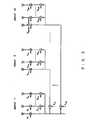
- Fig. 3shows an example configuration of the transmitting antennas of a base station according to the preferred embodiment of the present invention.
- transmitting antennascompose a plurality of groups, each consisting of a plurality of antennas. Transmitting antennas in the same group are located close to one another so that the fading correlation between the antennas is high and groups are installed apart from one another so that the fading correlation between the groups is low. Fading correlation is a numeric value indicating how similarly two signals transmitted from different antennas fade when the signals are received on a receiving side. Doppler effect and the like cause fading by reflection on buildings and mobile objects. Therefore, if a plurality of antennas transmitting signals are located close to one another, it follows that a mobile station receives the respective signals through similar routes. Accordingly, the signals suffer from similar fading.
- the fading correlation between the signalsis high. If a plurality of antenna transmitting signals are located apart from one another, it follows that the respective signals take different routes to a mobile station receives the signals. Therefore, the signals fade differently and then are received by the mobile station. In such a case, it is said that the fading correlation between the signals is low.
- an antenna control amount between groupsis calculated in a shorter cycle than that of the antenna control amount within a group, and is transmitted to a base station side as feedback information.
- Signals from base-station transmitting antennas in the same grouphave a high fading correlation; the signals suffer from almost the same fading, but the signals each have a phase difference depending on the angle at which the signals reach the receiving antenna of the mobile station. Therefore, each channel response estimation value estimated using the signals from the plurality of base-station transmitting antennas in the same group has a phase difference that depends on the angle of the mobile station against the base station. Although these values change as the mobile station travels, the values change slowly compared with fading fluctuations.
- each of the control amounts of antennas other than the reference antenna in the relevant groupis normalized by the control amount of this reference antenna (each relative value calculated using the control amount of this reference antenna as a reference is used).
- This normalized antenna control amount in the groupchanges slowly as the mobile station travels. Therefore, the control cycle can be made relatively long.
- respective channel response estimation valueschannel impulse response vector
- An antenna control amount obtained by normalizing the reference antenna control amount of one specific group by the reference antenna control amount of another groupis defined as an inter-group antenna control amount. Since each inter-group antenna control amount changes quickly due to each independent fading fluctuation, in order to accurately control antennas, the control must be exercised in a short cycle.
- the mobile stationmust recognize which signal comes from which group. However, it is sufficient to relate each antenna to each pilot signal transmitted from the antenna in advance. Since pilots are mutually orthogonal to one another, a receiving side can accurately recognize from which antenna the signal is transmitted by checking the pilot signal.
- Both the inter-group antenna control amount F 1,m and intra-group antenna control amount G m,k shown in Fig. 3are calculated as follows.
- Fading fluctuation rateis expressed by Doppler frequency.
- f d⁇ ⁇
- vis the travel speed of a mobile station and ⁇ is the carrier wavelength.
- f dbecomes approximately 111Hz.
- the angle of arrival of an incoming wavechanges as the mobile station travels. For example, if the mobile station travels at a speed of 200km/h at a place 200 meters ahead, the input angle changes by approximately 15 degrees per second. In this way, the fading fluctuation rate is higher by several tens of times to several hundreds of times than the fluctuation rate of an input angle.
- a feedback amount of informationcan be reduced without performance degradation.
- an inter-group antenna control amount changing at a high speedis updated and fed back in a short cycle, while each intra-group antenna control amount changing slowly compared with the inter-group antenna control amount is updated and fed back in a longer cycle.
- the frequency of updatesis made large.
- the change of intra-group diversity control with a high fading correlationis slower than that of the data speed of feedback information, the frequency of updates is made small.
- each intra-group antenna control amounthas been related to the angle of the mobile station with respect to the base station, in a macro-cell system with a relatively large cell radius, the deviation of an input angle becomes negligibly small. Therefore, a specific intra-group antenna control amount can also be used as the intra-group antenna control amount of another group. Specifically, transmitting only the intra-group control information of one specific group and controlling the antennas in the other group using this information can further reduce an amount of feedback information.
- Fig. 4shows the configuration of one preferred embodiment of the present invention.
- Each transmitting antenna 31transmits the pilot signal to a mobile station.
- a receiving antenna 32receives the four pilot signals transmitted from each of four transmitting antennas, and a control amount calculation unit 33 estimates the channel of signals transmitted from each transmitting antenna 31 using the respective pilot signal.
- the channel impulse response vectoris obtained from each signal and a weight vector that maximizes equation (5) is calculated. Since a method for calculating this weight vector is already publicly known, the description is omitted.
- the control amount calculation unit 33transfers the vector to a multiplex unit 34 as feedback information.
- the multiplex unit 34multiplexes the feedback information with an upward data signal and transmits the information from a transmitting antenna 35.
- a receiving antenna 36receives the signal from the mobile station, and a feedback information extraction unit 37 extracts the feedback information from the signal.
- the extracted feedback informationis inputted to an amplitude/phase control unit 38, each weight coefficient w 1 , w 2 and w 3 included in the feedback information is multiplied to the respective downward transmitting data signal of each corresponding antenna, and the transmitting antennas 31 transmit the downward transmitting data signals.
- a closed loop for performing transmitting diversity controlincluding a base station and a mobile, is implemented.
- Fig. 5shows examples of a downlink pilot signal pattern in this preferred embodiment.
- each corresponding codeis multiplied by each of the pilot signals P 1 through P 4 shown in Fig. 5, and the products of the entire pilot signal pattern are added up the result "0" is obtained.
- the pilot signals P 1 through P 4form a mutually orthogonal code word.
- Each pilot signal's amplitude and phase change independently due to fading, and the combination of these signalsis received by the antenna of a mobile station.
- a mobile-station receivercan calculate the channel response estimation values h 1 , h 2 , h 3 and h 4 of each pilot signal by correlating the incoming pilot signals with corresponding pilot signals P 1 (t), P 2 (t), P 3 (t) and P 4 (t), respectively, that are stored in advance on the mobile station side and by averaging the obtained correlations.
- Fig. 6shows both an example configuration of base-station transmitting antennas according to this preferred embodiment and antenna control information thereof.
- Fig. 6Ashows the transmitting antenna configuration of a base station. It is assumed that antennas ANT1 and ANT2 form group 1, and antennas ANT3 and ANT4 form group 2. It is also assumed that antennas ANT1 and ANT3 are the reference antenna of groups 1 and 2, respectively. It is further assumed that antenna ANT1 is also the reference antenna of all the groups 1 and 2. Antennas ANT1 and ANT2 are located apart from each other by one wavelength. Antennas ANT3 and ANT4 are also located apart from each other by one wavelength. Antennas ANT1 and ANT3 are located apart from each other by 20 wavelengths. Antennas ANT2 and ANT4 are also located apart from each other by 20 wavelengths.
- the envelope correlation coefficient of input wavesis expressed as follows.
- dthe distance between two antennas.
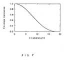
- the angle dispersion ⁇ of each input signal observed at the base station in a macro-cell environmentis approximately 3 degrees.
- Fig. 7shows the envelope correlation coefficient in this case. It is seen from Fig. 7 that at d ⁇ 19 ⁇ the input signals become uncorrelated. Therefore, according to the present invention, fading correlation can be made low by setting the distance between antenna groups to approximately 19 wavelengths or more. Fading correlation can also be made high by setting the distance between antennas in each group to one wavelength or less.
- fading correlationis affected by a variety of factors, such as the height at which the antenna is installed, the size of the antenna and the like. Therefore, it is acceptable if the antennas are installed so that the distance between any two antennas in the same group is approximately the wavelength of an incoming signal. However, a person having ordinary skill in the art should set the distance between groups so that fading correlation is almost "0" in any situation.
- ⁇ i Qis a quantized control amount
- Figs. 8 through 11show examples of the transmission format of feedback information in this preferred embodiment.
- this feedback informationis multiplexed with an upward channel so that the transmission rate of b 3 may become higher than the transmission rate of b 1 or b 2 and is transmitted to a base station.
- One frame of length 10msis composed of 15 slots in compliance with the W-CDMA frame format. This transmission format transmits feedback information of one bit in each slot. Format1 transmits both one b 1 and one b 2 in one frame, and format2 transmits both two b 1 and two b 2 in one frame.
- the phase control of each transmitting antennais conducted using the feedback information received in an uplink channel.
- a corresponding antennais directly controlled by the feedback information received in the immediately previous slot.
- antennas other than the corresponding antennastore the latest feedback information and use the information for their control.
- ANT4 shown in Fig. 6Ais controlled not only by control amount d2, but also by the control amount d3 of ANT 3. Specifically, ANT4 is frequently controlled by d3 and is also controlled by d2 less frequently. This description also applies to ANT4 shown in Fig. 6B.
- Filtering feedback informationcan also reduce the number of transmission errors and the number of quantization errors. For example, for the filtering, a method using the average value of the control amount of the feedback information received in the immediately previous slot and the control amount of the feedback information received in receiving slots before the immediately previous slot is used.
- an updated control amountis transmitted every time the feedback information is transmitted.
- the same feedback informationcan also be repeatedly transmitted. In this case, the number of transmission errors in the base station can be reduced by combining a plurality of pieces of feedback information received in the frame.
- each intra-group antenna control amountrelates to the angle of a mobile station against the base station in a macro-cell system with a to some extent large cell radius, the deviation of the input angle within a group is negligibly small. Therefore, if control is exercised within each group using the same intra-group antenna control amount, there is no problem. Therefore, transmitting only the intra-group control information of one specific group and controlling other groups using this information can further reduce an amount of feedback information.
- Fig. 9shows a feedback information transmission format used to transmit only b 1 as intra-group control information.
- Format3transmits two b 1 in one frame and format 4 transmits four b 1 in one frame.
- an updated control amountcan be transmitted every time the feedback information is transmitted.
- the same feedback informationcan be repeatedly transmitted within the same frame.
- Fig. 10shows the feedback information transmission format in which b 1 and b 3 are quantized using three bits and four bits, respectively- Tables 1 and 2 of Fig. 11 show the correspondence between the feedback information b 3 of an inter-group antenna control amount and a control amount.
- Table 3shows the correspondence between the feedback information b 1 of an intra-group antenna control amount and a control amount.
- feedback information bit b 3is composed of four bits; three bits of b 3 (3) through b 3 (1) representing a phase control amount and one bit of b 3 (0) representing an amplitude control amount.
- Format5 shown in Fig. 10includes feedback information bit b 3 in one frame. However, three words of feedback information bit b1 are composed of three bits of b 1 (2) through b 1 (0) representing a phase control amount. According to format5 shown in Fig. 10, three bits of feedback information bit b 1 are distributed and located in one frame, and all the three bits together form one word.
- Fig. 12shows an example configuration of a mobile station that transmits feedback information to a base station according to the formats shown in Figs. 8 through 11.
- a mobile stationOn receipt of a signal from a base station via its receiving antenna, a mobile station branches the receiving signal into two signals and inputs one signal and the other signal to a data channel despreading unit 41 and a pilot channel despreading unit 44, respectively.
- the data channel dispreading unit 41despreads the data channel signal and inputs the signal to both a channel estimation unit 42 and a receiver 43.
- the receiver 43reproduces the downlink data signal, based on the channel estimation result of the channel estimation unit 42 and presents the signal to a user as voice or data.
- the pilot channel dispreading unit 44despreads the incoming signal using a pilot channel dispreading code and inputs the signal to a channel estimation unit 45.
- a control amount calculation unit 46calculates a weight vector based on these channel estimation values and determines feedback information to be transmitted.
- a multiplex unit 47multiplexes this feedback information with an upward control channel.
- a data modulation unit 48modulates the feedback information.
- a spreading modulation unit 49spread-modulates the feedback information. Then, the feedback information is transmitted to the base station from a transmitting antenna 50.
- a base stationuses both uplink feedback information and an uplink channel arriving method estimation result as intra-group antenna control information.
- input direction estimation units 62 and 63estimate the arriving direction of an incoming signal based on an uplink receiving signal received by an array antenna (a plurality of antennaslements used in transmission diversity: transmitting/receiving antenna 60). Since arriving direction strongly depends on the angle of a mobile station against a base station, a method for setting the direction of a downlink transmitting beam (direction in which the strength of a wave transmitted from an antenna is large) to this uplink signal input direction is known. However, in a system where uplink and downlink frequencies are different, this assumption does not always hold true and depends on the propagation environment.
- a receiving processing unit 61Upon receipt of the uplink feedback information via an antenna 60, a receiving processing unit 61 performs the despeading and the like of the uplink feedback information and relays the information to a feedback information extraction unit 37.
- a feedback information extraction unit 37extracts a control amount from the uplink feedback information
- an amplitude/phase control unit 38'compares the control amount with the arriving direction estimation value and determines to use either the control amount received from the uplink line or the arriving direction estimation value. Then, the unit 38' controls the amplitude/phase of a transmitting signal.
- the intra-group phase differenceis not within a specific range [ ⁇ - ⁇ , ⁇ - ⁇ ] with the arriving direction estimation result ⁇ of the uplink channel as a center, control is exercised using only the arriving direction estimation result ⁇ since the control amount by the upward feedback information is related to an uplink channel arriving direction estimation result ⁇ . Specifically, if the control amount in the feedback information is too far from the arriving direction estimation result ⁇ , it is judged that a bit error or the like has occurred during transmission of the feedback information, and the feedback information is inaccurate. Then, the feedback information is discarded and only phase is controlled using the arriving direction estimation result ⁇ .
- a control amount in the uplink feedback information of intra-group phase difference informationcan be sampled for a prescribed time period. If it is judged that variance of the samples is large (for example, specifically, if the samples are dispersed more widely than a specific predetermined threshold value) , control can be exercised using only the arriving method estimation result ⁇ without utilizing the feedback information.
- Fig. 15shows the configuration of the third preferred embodiment of the present invention.
- the transmitting powers of pilot signals P 1 and P 3are set smaller than the transmitting powers of pilot signals P 2 and P 4 , respectively.
- thisis implemented by multiplying pilot signals P 2 and P 4 by a coefficient ⁇ (0 ⁇ 1).
- pilot signals P 2 and P 4are needed to estimate channel impulse response vectors h 2 and h 4
- h 2 and h 4have high fading correlations to h 1 and h 3 , respectively. Therefore, h 2 / h 1 and h 4 / h 3 that are normalized by them strongly depend on an angle of the mobile station against the base station.
- estimation accuracycan be improved by taking a long time average of pilot signals P 2 and P 4 even if an incoming power is low.
- estimation values ⁇ 1 (n), ⁇ 2 (n) and ⁇ 3 (n) at the n-th slotcan be calculated as follows. In these equations, N is the estimated average number of slots of estimation values ⁇ 1 (n) and ⁇ 2 (n).
Landscapes
- Engineering & Computer Science (AREA)
- Computer Networks & Wireless Communication (AREA)
- Signal Processing (AREA)
- Power Engineering (AREA)
- Physics & Mathematics (AREA)
- Mathematical Physics (AREA)
- Mobile Radio Communication Systems (AREA)
- Radio Transmission System (AREA)
- Variable-Direction Aerials And Aerial Arrays (AREA)
Description
- The present invention relates to a transmitting diversity communications apparatus.
- Transmitting diversity in W-CDMA, which is the third-generation mobile communications system, adopts a method using two transmitting antennas.
- Fig. 1 shows an example configuration of a transmitting diversity system using two transmitting antennas.
- Mutually orthogonal pilot patterns P1 and P2 are transmitted from two transmitting
antennas - A control
amount calculation unit 10 calculates and quantizes the amplitude/phase control vector (weight vector)w=[w1, w2] of each transmitting antenna of the base station that maximizes power P expressed by the following equation (1) using these channel estimation values. Then, amultiplex unit 11 multiplexes the quantized weight vectors with an uplink channel signal as feedback information and transmits the signal to the base station. However, since there is no need to transmit both values w1 and w2, it is acceptable to transmit only value w2 obtained by assigning w1=1.

- In equation (2),h1 andh2 are the channel impulse response vectors from the
transmitting antennas 
- Therefore, in the case of two transmitting antennas, equation (1) is calculated based on the following algebraic calculation.

- At the time of handover, weight vectorw that maximizes the following equation is calculated instead of equation (1).

- In equation (4), Hk is a channel impulse response signal from the k-th base station.
- Then, the feedback
information extraction unit 12 on the transmitting side extracts w2 (in this case, w1=1 is assumed) transmitted from a mobile station, from an incoming signal and an amplitude/phase control unit 13 multiplies a data signal to be transmitted from the transmittingantenna 2 by w2. In this way, the degradation of both the amplitude and phase of signals received from the transmittingantennas - In W-CDMA, two methods are stipulated:
mode 1 for quantizing weight coefficient w2 into one bit andmode 2 for quantizing w2 into four bits. Inmode 1, since control is exercised by transmitting one bit of feedback information for each slot, control speed is high. However, since quantization is rough, accurate control is impossible. Inmode 2, since control is exercised by transmitting four bits of information, more accurate control is possible. However, inmode 2, since only one bit can be transmitted for each slot and feedback information of one word is transmitted for every four slots, control cannot track fading in the case of a high fading frequency, and amplitude/phase characteristics degrade. As described above, if the signal transfer rate of an uplink channel from a mobile station to a transmitting station, for transmitting feedback information is restricted, control accuracy and fading track speed have an inverse relationship. - The Release-99 specification of W-CDMA standard does not take into consideration a case where more than two transmitting antennas are used so as to avoid the degradation of uplink channel transmission efficiency due to feedback information transmission. However, if the increase of feedback information or the degradation of update speed is allowed, the number of antennas can also be increased to three or more. In particular, currently a case where four transmitting antennas are used is being extensively researched and developed.
- If a closed-loop transmitting diversity system is applied to the radio base station of a cellular mobile communications system, a signal from each transmitting antenna independently suffers from fading, and ideally the same phase combination is performed at the antenna position of the mobile station. Therefore, a diversity gain corresponding to the number of transmitting antennas can be obtained and the gain can also be improved by the combination. Accordingly, the receiving characteristic is improved and the number of users accommodated in one cell can also be increased. "Ideally" means a case where there is neither transmission error of feedback information, control delay, channel response estimation error nor quantization error of a control amount. In reality, the characteristic degrades due to these factors compared with that of the ideal case.
- In order to obtain a diversity gain corresponding to the number of antennas, antenna spacings (the distances between antennas) must be wide so that fading correlation may become sufficiently low. Generally, in order to suppress fading correlation to a sufficiently low level in the radio base station of a cellular mobile communications system, antenna spacings must be approximately 20 wavelengths. Since one wavelength is approximately 15cm in a 2GHz band, antennas must be installed approximately 3 meters apart. Therefore, if the number of transmitting antennas increases, an area needed to install antennas becomes wide and it becomes difficult to install antennas on the roof of a building and the like, which is a problem. Diversity gain is saturated as the number of transmitting antennas increases. Therefore, when the number of transmitting antennas reaches a specific value, the diversity gain cannot be improved any further even if the number of transmitting antennas is further increased.
- When the number of transmitting antennas is increased, an amount of information to be fed back increases since feedback information must be transmitted to each antenna. Therefore, in that case, the transmission efficiency of an uplink channel degrades due to feedback information transmission or the control of transmitting diversity cannot track high-speed fading. As a result, the characteristic degrades, which is another problem.
- In the document "Advanced closed loop Tx diversity concept" (eigenbeamformer), 3GPP TSG RAN WG 1, 4-7 July 2000, XP-002169992 there is described a technology for accomplishing a long-term control and short-term control using eigenbeams.
- In the document "An extension of closed loop
Tx diversity mode 1 for multiple Tx antennas", 3GPP TSG RAN WG1, 22-25 May 2000, XP-002305498, closed Tx diversity to improve downlink performance is discussed. This document discusses a technology associated with generation of a feedback command. - An object of the present invention is to provide a transmitting diversity communications apparatus for suppressing the increase of uplink feedback information if the number of transmitting antennas is increased, suppressing the degradation of a characteristic in the case of a high fading frequency and requiring a small antenna installation space in the base-station.
- According to one aspect of the present invention there is provided a base station for transmitting signals using a transmitting diversity method to a mobile station and for controlling the transmitted signals according to information from the mobile station, the base station being characterized by comprising: antenna means of the base station composed of a plurality of antenna groups, each group consisting of a plurality of antennas located close to one another so that fading correlation between the antennas is high, and the antenna groups are located apart from one another so that fading correlation between the groups is low; and control means of the base station for receiving both first control information for intra-group antenna control, with a prescribed transfer rate, and second control information for inter-antenna group control, with a higher transfer rate than the prescribed transfer rate that are transmitted from a mobile station, and controlling a phase of a signal transmitted by the antenna means.
- According to another aspect of the present invention there is provided a mobile station for a transmitting diversity communications system, the system including a base station for transmitting signals using a transmitting diversity method to a said mobile station and for controlling the transmitted signals according to information from the mobile station, the mobile station being characterized by comprising: receiving means for receiving a signal transmitted from an antenna means of a said base station composed of a plurality of antenna groups, each group consisting of a plurality of antennas located close to one another so that fading correlation between the antennas is high, and the antenna groups are located apart from one another so that fading correlation between the groups is low; antenna specifying means for identifying an antenna that has transmitted the received signal; and transmitting means for transmitting first control information about intra-group antenna control of the received signal to the said base station at a prescribed transfer rate and transmitting second control information about inter-group antenna control of the received signal to the said base station at a higher transfer rate than the prescribed transfer rate.
- According to a further aspect of the present invention there is provided a transmitting diversity communications method for use in a system including a base station for transmitting signals using a transmitting diversity method to a mobile station and for controlling the transmitted signals according to information from the mobile station, the method being characterized by comprising: providing a plurality of antenna groups of the base station, each group consisting of a plurality of antennas, placing the antennas in the same group close to one another so that fading correlation between the antennas in the same group is high and placing the antenna groups apart from one another so that fading correlation between the groups is low; and receiving at the base station both first control information for intra-group antenna control, with a low transfer rate and second control information for inter-antenna group control, with a high transfer rate that are transmitted from a mobile station and controlling the phase of a signal transmitted by the antenna unit.
- The transmitting diversity communications apparatus of the present invention includes a transmitting diversity base station for controlling transmitting signals, according to information from a mobile station. The transmitting diversity communications apparatus comprises an antenna unit composed of a plurality of antenna groups, each consisting of a plurality of antennas, located close to each other so that the fading correlation between the antennas in the same group is high and groups are located apart from one another so that the fading correlation between the groups is low, and a control unit receiving both the first control information about intra-group antenna control with a low transfer rate that is transmitted from a mobile station and the second control information about inter-group antenna control and controlling the phase of a signal transmitted by the antenna unit.
- According to the present invention, if signal control is applied to a closed-loop transmitting diversity system by the same method as in the conventional case where two transmitting antennas are used, by increasing the number of transmitting antennas, the tracking of fading fluctuations and transmitting-signal control performance can be prevented from degrading due to the increase of an amount of information to be transmitted from a mobile station to a base station.
- In particular, according to the present invention, since the antenna unit of a base station is composed of a plurality of antenna groups each consisting of a plurality of antennas, and each intra-group antenna and each antenna group is set so that fading correlation is high within a group and so that fading correlation is low between groups, respectively, only transmitting-signal control information between groups must be transmitted at a high speed from a mobile station to a base station and transmitting-signal control information within a group can be relatively slow. Therefore, transmitting diversity performance can be improved by effectively utilizing the limited transfer rate of an upward line from a mobile station to the base station.
- Fig. 1 shows an example configuration of a transmitting diversity system using two transmitting antennas.
- Fig. 2 shows the system configuration of the present invention.
- Fig. 3 shows an example configuration of transmitting antennas of a base station according to the preferred embodiment of the present invention.
- Fig. 4 shows the configuration of one preferred embodiment of the present invention.
- Fig. 5 shows an example of a downlink pilot signal pattern in the preferred embodiment.
- Fig. 6 shows both an example configuration of a base station transmitting antennas and antenna control information according to the preferred embodiment.
- Fig. 7 shows an envelope correlation coefficient obtained when the angle dispersion Δφ of an input signal observed at a base station in a macro-cell environment is approximately 3.
- Fig. 8 shows an example of the transmission format of feedback information in the preferred embodiment (No. 1).
- Fig. 9 shows an example of the transmission format of feedback information in the preferred embodiment (No. 2).
- Fig. 10 shows an example of the transmission format of feedback information in the preferred embodiment (No. 3).
- Fig. 11 shows an example of the transmission format of feedback information in the preferred embodiment (No. 4).
- Fig. 12 shows an example configuration of a mobile station for transmitting feedback information to a base station according to the formats shown in Figs. 8 through 11.
- Fig. 13 shows an example configuration of a base station in the second preferred embodiment of the present invention.
- Fig. 14 shows an antenna phase difference control method within a group in the second preferred embodiment.
- Fig. 15 shows the configuration of the third preferred embodiment of the present invention.
- The present invention relates to a closed-loop transmitting diversity method according to which the radio base station of a cellular mobile communications system is provided with a plurality of antennaslements, both different amplitude and phase control are exercised over the same transmitting data, according to feedback information from a mobile station and a plurality of pieces of data are transmitted using different antennas. On the mobile station side, the amplitude/phase control amounts are determined using a downward pilot signal; feedback information indicating the amplitude/phase control amounts are multiplexed with an uplink channel signal; and the data is transmitted to the base station.
- Fig. 2 shows the system configuration of the present invention.
- The pilot
signal generation unit 20 of a base station generates N mutually orthogonal pilot signals P1(t), P2(t), ..., PN(t) and the pilot signals are transmitted using different antennas. N is the number of transmitting antennas. The following relationship is established between these pilot signals.
- Each pilot signal suffers from both amplitude and phase fluctuations due to fading, and a signal obtained by combining these pilot signals is transmitted to the receiving
antenna 22 of a mobile station. The receiver of the mobile station estimates the channel impulse response vectors h1, h2, ..., hN of each pilot signal by calculating the correlation between the incoming pilot signal and each of P1 (t), P2 (t), ..., PN(t). - A control
amount calculation unit 23 calculates and quantizes the amplitude/phase control vector (weight vector)w=[w1, w2, ..., wN]T of each transmitting antenna of the base station that maximizes power P expressed by equation (5)(the same as equation (1)) using these channel impulse response vectors. A multiplex unit 24 multiplexes the quantized vector with an upward channel signal as feedback information and transmits the signal to the base station side. However, in this case it is acceptable to transmit values w2, w3, ..., wN obtained by assigning w1=1.

- In equation (6),h1 is a channel impulse response vector from transmitting antenna i. If an impulse response length is assumed to be L, h1 is expressed as follows.

- At the time of hand-over, weight vectorw that maximizes the following equation is calculated instead of equation (5).

- In equation (8), Hk is a channel impulse response signal from the k-th base station, and is the same as Hk in equation (4).
- The multiplex unit 24 of the mobile station multiplexes the weight vector obtained in this way with an upward transmitting data signal and the vector is transmitted to the receiving antenna of the base station. In the base station, a feedback
information extraction unit 25 extracts the feedback information received by a receiving antenna, and an amplitude/phase control unit 26 controls both the amplitude and phase transmitted from each transmitting antenna using a weight vector included in the feedback information. When the base station transmits a signal, both the amplitude and phase of which have been controlled from a transmittingantenna 21, the mobile station receives the signal as if the fluctuations due to just fading of both the amplitude and phase were compensated for. Therefore, optimal reception is possible. Since fading changes as time elapses, both the generation and transmission of feedback information must happen in real time. However, since both the transmission format and transfer rate of an uplink data signal from a mobile station to a base station is predetermined, it takes too much time to transmit a lot of information. Therefore, the control cannot track the fading fluctuations. In order to track the fading fluctuations, the transmission rate of feedback information must be high. However, since the transmission rate of an uplink control channel is limited, if a plurality of pieces of new information are sequentially transmitted in a short cycle in order to control transmitting diversity at a high speed, an amount of information included in one time transmission becomes small (quantization becomes rough), and highly accurate control becomes impossible. - In the preferred embodiment of the present invention, each coefficient value in a weight vector is calculated and fed back in a different cycle instead of calculating and feeding back a signal transmitted from each antenna in the same cycle.
- The details are described below.
- Fig. 3 shows an example configuration of the transmitting antennas of a base station according to the preferred embodiment of the present invention.
- As shown in Fig. 3, in a base station, transmitting antennas compose a plurality of groups, each consisting of a plurality of antennas. Transmitting antennas in the same group are located close to one another so that the fading correlation between the antennas is high and groups are installed apart from one another so that the fading correlation between the groups is low. Fading correlation is a numeric value indicating how similarly two signals transmitted from different antennas fade when the signals are received on a receiving side. Doppler effect and the like cause fading by reflection on buildings and mobile objects. Therefore, if a plurality of antennas transmitting signals are located close to one another, it follows that a mobile station receives the respective signals through similar routes. Accordingly, the signals suffer from similar fading. In such a case, it is said that the fading correlation between the signals is high. If a plurality of antenna transmitting signals are located apart from one another, it follows that the respective signals take different routes to a mobile station receives the signals. Therefore, the signals fade differently and then are received by the mobile station. In such a case, it is said that the fading correlation between the signals is low.
- In a mobile station, an antenna control amount between groups is calculated in a shorter cycle than that of the antenna control amount within a group, and is transmitted to a base station side as feedback information. Signals from base-station transmitting antennas in the same group have a high fading correlation; the signals suffer from almost the same fading, but the signals each have a phase difference depending on the angle at which the signals reach the receiving antenna of the mobile station. Therefore, each channel response estimation value estimated using the signals from the plurality of base-station transmitting antennas in the same group has a phase difference that depends on the angle of the mobile station against the base station. Although these values change as the mobile station travels, the values change slowly compared with fading fluctuations. One antenna in each group is designated as a reference antenna, and each of the control amounts of antennas other than the reference antenna in the relevant group is normalized by the control amount of this reference antenna (each relative value calculated using the control amount of this reference antenna as a reference is used). This normalized antenna control amount in the group changes slowly as the mobile station travels. Therefore, the control cycle can be made relatively long.
- However, since respective signals from base-station transmitting antennas belonging to different groups have a low fading correlation, the signals fade differently and independently by the time they reach the receiving antenna of the mobile station. Therefore, respective channel response estimation values (channel impulse response vector) estimated using respective signals from respective reference values belonging to different groups change quickly due to respective independent fading fluctuations. An antenna control amount obtained by normalizing the reference antenna control amount of one specific group by the reference antenna control amount of another group is defined as an inter-group antenna control amount. Since each inter-group antenna control amount changes quickly due to each independent fading fluctuation, in order to accurately control antennas, the control must be exercised in a short cycle.
- The mobile station must recognize which signal comes from which group. However, it is sufficient to relate each antenna to each pilot signal transmitted from the antenna in advance. Since pilots are mutually orthogonal to one another, a receiving side can accurately recognize from which antenna the signal is transmitted by checking the pilot signal.
- Both the inter-group antenna control amount F1,m and intra-group antenna control amount Gm,k shown in Fig. 3 are calculated as follows. In the description given above, N, M and K=N/M are the total number of antennas, the number of antenna groups and the number of antennas in each group, respectively. * represents complex conjugation.
- Intra-group reference antenna: Antenna #((m-1)K+1) (m-1, ..., M)


- Since fading correlation is high within a group, |Gm,k|=1 can be assigned. Specifically, it can be considered that the change due to fading is small within a group, and it is sufficient to take into consideration only change in phase. In order to keep total transmission power constant (=1.0), F1,m must be normalized as follows.

- Next, the fluctuation rate of fading is described.
- Fading fluctuation rate is expressed by Doppler frequency.

- In the equation described above, v is the travel speed of a mobile station and λ is the carrier wavelength. For example, if a carrier frequency is 2GHz and the travel speed of a mobile station is 60km/h, fd becomes approximately 111Hz. However, the angle of arrival of an incoming wave changes as the mobile station travels. For example, if the mobile station travels at a speed of 200km/h at a place 200 meters ahead, the input angle changes by approximately 15 degrees per second. In this way, the fading fluctuation rate is higher by several tens of times to several hundreds of times than the fluctuation rate of an input angle. According to W-CDMA standards, a slot length is 666. 7µs and the update speed of feedback information is 1500Hz. Therefore, if information about fading is not updated for each slot, a track characteristic degrades. However, there is no need to feedback information about input angle for each slot. For example, there will be no problem if information is updated for every 15 slots (=one frame).
- By utilizing the difference in the fluctuation rates of the control information described above, a feedback amount of information can be reduced without performance degradation. Specifically, an inter-group antenna control amount changing at a high speed is updated and fed back in a short cycle, while each intra-group antenna control amount changing slowly compared with the inter-group antenna control amount is updated and fed back in a longer cycle. In other words, since the change of inter-group diversity control with a low fading correlation is faster than that of the data speed of feedback information, the frequency of updates is made large. However, since the change of intra-group diversity control with a high fading correlation is slower than that of the data speed of feedback information, the frequency of updates is made small.
- Since each intra-group antenna control amount has been related to the angle of the mobile station with respect to the base station, in a macro-cell system with a relatively large cell radius, the deviation of an input angle becomes negligibly small. Therefore, a specific intra-group antenna control amount can also be used as the intra-group antenna control amount of another group. Specifically, transmitting only the intra-group control information of one specific group and controlling the antennas in the other group using this information can further reduce an amount of feedback information.
- Fig. 4 shows the configuration of one preferred embodiment of the present invention.
- A case where the number of antennas N=4 and the number of antenna groups M=2 is described. A pilot
signal generation unit 30 generates N=4 pilot signals P1(t), P2(t), P3(t) and P4(t), and each of the signals is transmitted from one of transmittingantennas 31. These pilot signals use mutually orthogonal bit sequences. - Each transmitting
antenna 31 transmits the pilot signal to a mobile station. In the mobile station, a receivingantenna 32 receives the four pilot signals transmitted from each of four transmitting antennas, and a controlamount calculation unit 33 estimates the channel of signals transmitted from each transmittingantenna 31 using the respective pilot signal. As a result, the channel impulse response vector is obtained from each signal and a weight vector that maximizes equation (5) is calculated. Since a method for calculating this weight vector is already publicly known, the description is omitted. When the weight vector is calculated, the controlamount calculation unit 33 transfers the vector to amultiplex unit 34 as feedback information. Themultiplex unit 34 multiplexes the feedback information with an upward data signal and transmits the information from a transmittingantenna 35. In a base station, a receivingantenna 36 receives the signal from the mobile station, and a feedbackinformation extraction unit 37 extracts the feedback information from the signal. The extracted feedback information is inputted to an amplitude/phase control unit 38, each weight coefficient w1, w2 and w3 included in the feedback information is multiplied to the respective downward transmitting data signal of each corresponding antenna, and the transmittingantennas 31 transmit the downward transmitting data signals. In this way, in this preferred embodiment, a closed loop for performing transmitting diversity control, including a base station and a mobile, is implemented. - Fig. 5 shows examples of a downlink pilot signal pattern in this preferred embodiment.
- If each corresponding code is multiplied by each of the pilot signals P1 through P4 shown in Fig. 5, and the products of the entire pilot signal pattern are added up the result "0" is obtained. Specifically, the pilot signals P1 through P4 form a mutually orthogonal code word.
- Each pilot signal's amplitude and phase change independently due to fading, and the combination of these signals is received by the antenna of a mobile station. A mobile-station receiver can calculate the channel response estimation values h1, h2, h3 and h4 of each pilot signal by correlating the incoming pilot signals with corresponding pilot signals P1(t), P2(t), P3 (t) and P4 (t), respectively, that are stored in advance on the mobile station side and by averaging the obtained correlations.
- Fig. 6 shows both an example configuration of base-station transmitting antennas according to this preferred embodiment and antenna control information thereof.
- Fig. 6A shows the transmitting antenna configuration of a base station. It is assumed that antennas ANT1 and
ANT2 form group 1, and antennas ANT3 andANT4 form group 2. It is also assumed that antennas ANT1 and ANT3 are the reference antenna ofgroups groups - Here, the spatial correlative characteristic of a base-station antenna is described.
- If the input angles of signals from mobile stations are uniformly distributed with dispersion Δφ, the envelope correlation coefficient of input waves is expressed as follows. In the equation, d represents the distance between two antennas.


- The angle dispersion Δφ of each input signal observed at the base station in a macro-cell environment is approximately 3 degrees. Fig. 7 shows the envelope correlation coefficient in this case. It is seen from Fig. 7 that at d≅19λ the input signals become uncorrelated. Therefore, according to the present invention, fading correlation can be made low by setting the distance between antenna groups to approximately 19 wavelengths or more. Fading correlation can also be made high by setting the distance between antennas in each group to one wavelength or less.
- However, fading correlation is affected by a variety of factors, such as the height at which the antenna is installed, the size of the antenna and the like. Therefore, it is acceptable if the antennas are installed so that the distance between any two antennas in the same group is approximately the wavelength of an incoming signal. However, a person having ordinary skill in the art should set the distance between groups so that fading correlation is almost "0" in any situation.
- Description will return to Fig. 6. In the following description it is assumed that amplitude is not controlled and only phase is controlled. Specifically, only a phase amount φi is controlled by assigning a1=1 to wi = aiejφ
i . As shown in Fig. 6B, each of the control amount φ1 of antenna ANT2 using antenna ANT1 as a reference, the control amount φ2 of antenna ANT4 using antenna ANT3 as a reference and the control amount φ3 of antenna ANT3 using antenna ANT1 as a reference is quantized and is transmitted to the base station as feedback information. If each of the control amounts is quantized using one bit, for example, the setting is as follows.
- In the expression, φiQ is a quantized control amount.
- Figs. 8 through 11 show examples of the transmission format of feedback information in this preferred embodiment.
- It is assumed that if φiQ=0, feedback information bi=0 and that if φiQ=π, feedback information bi=1. As shown in Fig. 8, this feedback information is multiplexed with an upward channel so that the transmission rate of b3 may become higher than the transmission rate of b1 or b2 and is transmitted to a base station. One frame of length 10ms is composed of 15 slots in compliance with the W-CDMA frame format. This transmission format transmits feedback information of one bit in each slot. Format1 transmits both one b1 and one b2 in one frame, and format2 transmits both two b1 and two b2 in one frame.
- In the base station, the phase control of each transmitting antenna is conducted using the feedback information received in an uplink channel. A corresponding antenna is directly controlled by the feedback information received in the immediately previous slot. In this case, antennas other than the corresponding antenna store the latest feedback information and use the information for their control.
- However, ANT4 shown in Fig. 6A is controlled not only by control amount d2, but also by the control amount d3 of
ANT 3. Specifically, ANT4 is frequently controlled by d3 and is also controlled by d2 less frequently. This description also applies to ANT4 shown in Fig. 6B. - Filtering feedback information can also reduce the number of transmission errors and the number of quantization errors. For example, for the filtering, a method using the average value of the control amount of the feedback information received in the immediately previous slot and the control amount of the feedback information received in receiving slots before the immediately previous slot is used.
- As the feedback information of an intra-group antenna control amount, an updated control amount is transmitted every time the feedback information is transmitted. However, for example, alternatively, in the same frame, the same feedback information can also be repeatedly transmitted. In this case, the number of transmission errors in the base station can be reduced by combining a plurality of pieces of feedback information received in the frame.
- Since each intra-group antenna control amount relates to the angle of a mobile station against the base station in a macro-cell system with a to some extent large cell radius, the deviation of the input angle within a group is negligibly small. Therefore, if control is exercised within each group using the same intra-group antenna control amount, there is no problem. Therefore, transmitting only the intra-group control information of one specific group and controlling other groups using this information can further reduce an amount of feedback information.
- Fig. 9 shows a feedback information transmission format used to transmit only b1 as intra-group control information. Format3 transmits two b1 in one frame and format 4 transmits four b1 in one frame.
- In this preferred embodiment too, as the feedback information of an intra-group antenna control amount, an updated control amount can be transmitted every time the feedback information is transmitted. Alternatively, for example, the same feedback information can be repeatedly transmitted within the same frame.
- Another transmission format in which a control amount calculated in a mobile station is quantized using a plurality of bits is described below.
- Fig. 10 shows the feedback information transmission format in which b1 and b3 are quantized using three bits and four bits, respectively- Tables 1 and 2 of Fig. 11 show the correspondence between the feedback information b3 of an inter-group antenna control amount and a control amount. Table 3 shows the correspondence between the feedback information b1 of an intra-group antenna control amount and a control amount.
- In this example, only the feedback information of an intra-group antenna control amount b1 is transmitted using the format shown in Fig. 9. As is clearly seen from Tables 1 and 2 of Fig. 11, feedback information bit b3 is composed of four bits; three bits of b3(3) through b3(1) representing a phase control amount and one bit of b3(0) representing an amplitude control amount. Format5 shown in Fig. 10 includes feedback information bit b3 in one frame. However, three words of feedback information bit b1 are composed of three bits of b1 (2) through b1 (0) representing a phase control amount. According to format5 shown in Fig. 10, three bits of feedback information bit b1 are distributed and located in one frame, and all the three bits together form one word.
- Fig. 12 shows an example configuration of a mobile station that transmits feedback information to a base station according to the formats shown in Figs. 8 through 11.
- On receipt of a signal from a base station via its receiving antenna, a mobile station branches the receiving signal into two signals and inputs one signal and the other signal to a data
channel despreading unit 41 and a pilotchannel despreading unit 44, respectively. The datachannel dispreading unit 41 despreads the data channel signal and inputs the signal to both achannel estimation unit 42 and areceiver 43. Thereceiver 43 reproduces the downlink data signal, based on the channel estimation result of thechannel estimation unit 42 and presents the signal to a user as voice or data. The pilotchannel dispreading unit 44 despreads the incoming signal using a pilot channel dispreading code and inputs the signal to achannel estimation unit 45. Thechannel estimation unit 45 correlates the despread signal to each pilot signal pattern and obtains channel estimation values H=[h1,h2,h3 andh4] for paths from each transmitting antenna to the mobile station. A controlamount calculation unit 46 calculates a weight vector based on these channel estimation values and determines feedback information to be transmitted. Amultiplex unit 47 multiplexes this feedback information with an upward control channel. Adata modulation unit 48 modulates the feedback information. A spreadingmodulation unit 49 spread-modulates the feedback information. Then, the feedback information is transmitted to the base station from a transmittingantenna 50. - In Fig. 13, the same reference numbers are attached to the same constituent components as those in Fig. 4 and their descriptions are omitted.
- In this preferred embodiment, a base station uses both uplink feedback information and an uplink channel arriving method estimation result as intra-group antenna control information. In the base station, input
direction estimation units - Upon receipt of the uplink feedback information via an
antenna 60, a receivingprocessing unit 61 performs the despeading and the like of the uplink feedback information and relays the information to a feedbackinformation extraction unit 37. When the feedbackinformation extraction unit 37 extracts a control amount from the uplink feedback information, an amplitude/phase control unit 38' compares the control amount with the arriving direction estimation value and determines to use either the control amount received from the uplink line or the arriving direction estimation value. Then, the unit 38' controls the amplitude/phase of a transmitting signal. - As shown in Fig. 14, in this preferred embodiment, if the intra-group phase difference is not within a specific range [θ-Δ,θ-Δ] with the arriving direction estimation result θ of the uplink channel as a center, control is exercised using only the arriving direction estimation result θ since the control amount by the upward feedback information is related to an uplink channel arriving direction estimation result θ. Specifically, if the control amount in the feedback information is too far from the arriving direction estimation result θ, it is judged that a bit error or the like has occurred during transmission of the feedback information, and the feedback information is inaccurate. Then, the feedback information is discarded and only phase is controlled using the arriving direction estimation result θ.
- Alternatively, a control amount in the uplink feedback information of intra-group phase difference information can be sampled for a prescribed time period. If it is judged that variance of the samples is large (for example, specifically, if the samples are dispersed more widely than a specific predetermined threshold value) , control can be exercised using only the arriving method estimation result θ without utilizing the feedback information.
- Fig. 15 shows the configuration of the third preferred embodiment of the present invention.
- In Fig. 15, the same reference numbers are attached to the same components as those in Fig. 4, and their descriptions are omitted.
- In this case, the transmitting powers of pilot signals P1 and P3 are set smaller than the transmitting powers of pilot signals P2 and P4, respectively. In this preferred embodiment, this is implemented by multiplying pilot signals P2 and P4 by a coefficient α (0<α≤1). Although pilot signals P2 and P4 are needed to estimate channel impulse response vectorsh2 andh4,h2 andh4 have high fading correlations toh1 andh3, respectively. Therefore,h2/h1 andh4/h3 that are normalized by them strongly depend on an angle of the mobile station against the base station. Since these values fluctuate slowly compared with fading fluctuation, estimation accuracy can be improved by taking a long time average of pilot signals P2 and P4 even if incoming power on the mobile station side is low. Both φ1 and φ2 are calculated as follows.

- Since interference to data signals by pilot signals can be suppressed to a low level by setting the transmitting powers of pilot signals P2 and P4 to a low level, transmission capacity can be increased.
- Since bothh2/h1 andh4/h3 depend on the angle of the mobile station against the base station and fluctuate more slowly than a fading fluctuation, estimation accuracy can be improved by taking a long time average of pilot signals P2 and P4 even if an incoming power is low. For example, estimation values φ1 (n), φ2 (n) and φ3 (n) at the n-th slot can be calculated as follows. In these equations, N is the estimated average number of slots of estimation values φ1 (n) and φ2 (n).


- In this way, when both φ1 and φ2 are calculated by taking a N-times time (number of slots) average of φ3, the same estimation accuracy as that of φ3 can be obtained even if α = 1/N. Specifically, in case N=4, α = 1/4 can be assigned.
- If the number of transmitting antennas is increased by utilizing differences in the fluctuation rate of control information, the following effects can be obtained.
- The increase in the amount of upward feedback information can be suppressed.
- Characteristics degrade little in the case of a high fading frequency.
- The antenna installation space of a base station can be reduced.


Claims (15)
- A base station (20,21,25,26) for transmitting signals using a transmitting diversity method to a mobile station (22,23,24) and for controlling the transmitted signals according to information from the mobile station (22,23,24), the base station beingcharacterized by comprising:antenna means (21) of the base station composed by a plurality of antenna groups, each group consisting of a plurality of antennas located close to one another so that fading correlation between the antennas is high, and the antenna groups are located apart from one another so that fading correlation between the groups is low; andcontrol means (26) of the base station for receiving both first control information for intra-group antenna control, with a prescribed transfer rate, and second control information for inter-antenna group control, with a higher transfer rate than the prescribed transfer rate, that are transmitted from a mobile station (22,23,24), and controlling a phase of a signal transmitted by the antenna means (21).
- The base station according to claim 1, and adapted to transmit pilot signals (P1 ... PN) to a mobile station (22,23,24) for the mobile station to use to determine a control amount of the phase.
- The base station according to claim 1, wherein said control means (26) is adapted also to control amplitude in addition to the phase.
- The base station according to claim 3, and adapted to transmit pilot signals (P1 ... PN) to a mobile station (22,23,24) for the mobile station to use to determine control amounts of both the phase and amplitude.
- The base station according to claim 4, and adapted for use with a mobile station (23) which is adapted to estimate a channel response (45) from each antenna to the mobile station by correlating a pilot signal from the base station to a known pilot signal on a mobile station side and calculating the control amount (46) using this channel response estimation value.
- The base station according to claim 1, and adapted for use with a mobile station which is adapted to transmit information (35;50) describing the difference in channel response estimation values between each intra-group antenna of said antenna means and a reference antenna and information describing the difference in channel response estimation values between each antenna group and a reference antenna of a specific antenna group to the base station as the first and second control information, respectively.
- The base station according to claim 1, and adapted for use with a mobile station which is adapted to transmit control information (35;50) about each antenna group and control information about an intra-group antenna within a specific antenna group to the base station as the second and first control information, respectively.
- The base station according to claim 1, wherein said control means of the base station controls the transmitting of a signal from the base station using an input direction estimation result (62,63) of an uplink channel signal in addition to the first and second control information.
- The base station according to claim 8, wherein if transmitting signal control amounts obtained from the first and second control information do not fall within a specific range with an arriving direction estimation result of the uplink channel signal as a center, transmission is controlled using the input direction estimation result.
- The base station according to claim 8, wherein if transmitting signal control amount dispersion obtained from the first control information is larger than a prescribed value, transmission is controlled using only an arriving direction estimation result.
- The base station according to claim 1, wherein control is exercised by a filtering result using both currently received first and second information and one or more previously received first and second control information.
- The base station according to claim 1, wherein the power of a signal transmitted from an antenna other than a reference antenna is set at a lower level than the power of a signal transmitted from a reference antenna of each antenna group.
- The base station according to claim 1, wherein the control means is adapted to control both amplitude and phase of the signal transmitted by the antenna means.
- A mobile station (22,23,24) for a diversity communications system, the system including a base station (20,21,25,26) for transmitting signals using a transmitting diversity method to a said mobile station and for controlling the transmitted signals according to information from the mobile station, the mobile station beingcharacterized by comprising:receiving means (22) for receiving a signal transmitted from an antenna means (21) of a said base station composed of a plurality of antenna groups, each group consisting of a plurality of antennas located close to one another so that fading correlation between the antennas is high, and the antenna groups are located apart from one another so that fading correlation between the groups is low;antenna specifying means for identifying an antenna that has transmitted the received signal; andtransmitting means for transmitting first control information about intra-group antenna control of the received signal to the said base station at a prescribed transfer rate and transmitting second control information about inter-group antenna control of the received signal to the said base station at a higher transfer rate than the prescribed transfer rate.
- A transmitting diversity communications method, for use in a system including a base station (20,21,25,26) for transmitting signals using a transmitting diversity method to a mobile station (22,23,24) and for controlling the transmitted signals according to information from the mobile station (22,23,24), the method beingcharacterized by comprising:providing a plurality of antenna groups (21) of the base station, each group consisting of a plurality of antennas, placing the antennas in the same group close to one another so that fading correlation between the antennas in the same group is high and placing the antenna groups apart from one another so that fading correlation between the groups is low; andreceiving at the base station both first control information for intra-group antenna control, with a prescribed transfer rate and second control information for inter-antenna group control, with a higher transfer rate than the prescribed transfer rate that are transmitted from a mobile station and controlling the phase of a signal transmitted by the antenna unit.
Priority Applications (2)
| Application Number | Priority Date | Filing Date | Title |
|---|---|---|---|
| EP05018898AEP1612966B1 (en) | 2000-08-10 | 2000-08-10 | Transmitting diversity communications apparatus |
| EP05018897AEP1603253B1 (en) | 2000-08-10 | 2000-08-10 | Transmitting diversity communications apparatus |
Applications Claiming Priority (1)
| Application Number | Priority Date | Filing Date | Title |
|---|---|---|---|
| PCT/JP2000/005380WO2002015433A1 (en) | 2000-08-10 | 2000-08-10 | Transmission diversity communication device |
Related Child Applications (2)
| Application Number | Title | Priority Date | Filing Date |
|---|---|---|---|
| EP05018898ADivisionEP1612966B1 (en) | 2000-08-10 | 2000-08-10 | Transmitting diversity communications apparatus |
| EP05018897ADivisionEP1603253B1 (en) | 2000-08-10 | 2000-08-10 | Transmitting diversity communications apparatus |
Publications (3)
| Publication Number | Publication Date |
|---|---|
| EP1315311A1 EP1315311A1 (en) | 2003-05-28 |
| EP1315311A4 EP1315311A4 (en) | 2005-01-19 |
| EP1315311B1true EP1315311B1 (en) | 2006-11-15 |
Family
ID=11736347
Family Applications (3)
| Application Number | Title | Priority Date | Filing Date |
|---|---|---|---|
| EP00950059AExpired - LifetimeEP1315311B1 (en) | 2000-08-10 | 2000-08-10 | Transmission diversity communication device |
| EP05018897AExpired - LifetimeEP1603253B1 (en) | 2000-08-10 | 2000-08-10 | Transmitting diversity communications apparatus |
| EP05018898AExpired - LifetimeEP1612966B1 (en) | 2000-08-10 | 2000-08-10 | Transmitting diversity communications apparatus |
Family Applications After (2)
| Application Number | Title | Priority Date | Filing Date |
|---|---|---|---|
| EP05018897AExpired - LifetimeEP1603253B1 (en) | 2000-08-10 | 2000-08-10 | Transmitting diversity communications apparatus |
| EP05018898AExpired - LifetimeEP1612966B1 (en) | 2000-08-10 | 2000-08-10 | Transmitting diversity communications apparatus |
Country Status (5)
| Country | Link |
|---|---|
| US (1) | US7099634B2 (en) |
| EP (3) | EP1315311B1 (en) |
| JP (1) | JP4176463B2 (en) |
| DE (3) | DE60037465T2 (en) |
| WO (1) | WO2002015433A1 (en) |
Cited By (35)
| Publication number | Priority date | Publication date | Assignee | Title |
|---|---|---|---|---|
| US7358912B1 (en) | 2005-06-24 | 2008-04-15 | Ruckus Wireless, Inc. | Coverage antenna apparatus with selectable horizontal and vertical polarization elements |
| US7498999B2 (en) | 2004-11-22 | 2009-03-03 | Ruckus Wireless, Inc. | Circuit board having a peripheral antenna apparatus with selectable antenna elements and selectable phase shifting |
| US7498996B2 (en) | 2004-08-18 | 2009-03-03 | Ruckus Wireless, Inc. | Antennas with polarization diversity |
| US7505447B2 (en) | 2004-11-05 | 2009-03-17 | Ruckus Wireless, Inc. | Systems and methods for improved data throughput in communications networks |
| US7511680B2 (en) | 2004-08-18 | 2009-03-31 | Ruckus Wireless, Inc. | Minimized antenna apparatus with selectable elements |
| US7525486B2 (en) | 2004-11-22 | 2009-04-28 | Ruckus Wireless, Inc. | Increased wireless coverage patterns |
| US7639106B2 (en) | 2006-04-28 | 2009-12-29 | Ruckus Wireless, Inc. | PIN diode network for multiband RF coupling |
| US7646343B2 (en) | 2005-06-24 | 2010-01-12 | Ruckus Wireless, Inc. | Multiple-input multiple-output wireless antennas |
| US7652632B2 (en) | 2004-08-18 | 2010-01-26 | Ruckus Wireless, Inc. | Multiband omnidirectional planar antenna apparatus with selectable elements |
| US7669232B2 (en) | 2006-04-24 | 2010-02-23 | Ruckus Wireless, Inc. | Dynamic authentication in secured wireless networks |
| US7696946B2 (en) | 2004-08-18 | 2010-04-13 | Ruckus Wireless, Inc. | Reducing stray capacitance in antenna element switching |
| US7877113B2 (en) | 2004-08-18 | 2011-01-25 | Ruckus Wireless, Inc. | Transmission parameter control for an antenna apparatus with selectable elements |
| US7880683B2 (en) | 2004-08-18 | 2011-02-01 | Ruckus Wireless, Inc. | Antennas with polarization diversity |
| US7933628B2 (en) | 2004-08-18 | 2011-04-26 | Ruckus Wireless, Inc. | Transmission and reception parameter control |
| US7965252B2 (en) | 2004-08-18 | 2011-06-21 | Ruckus Wireless, Inc. | Dual polarization antenna array with increased wireless coverage |
| US8009644B2 (en) | 2005-12-01 | 2011-08-30 | Ruckus Wireless, Inc. | On-demand services by wireless base station virtualization |
| US8031129B2 (en) | 2004-08-18 | 2011-10-04 | Ruckus Wireless, Inc. | Dual band dual polarization antenna array |
| US8203978B2 (en) | 2002-10-25 | 2012-06-19 | Qualcomm Incorporated | Multi-mode terminal in a wireless MIMO system |
| US8217843B2 (en) | 2009-03-13 | 2012-07-10 | Ruckus Wireless, Inc. | Adjustment of radiation patterns utilizing a position sensor |
| US8355343B2 (en) | 2008-01-11 | 2013-01-15 | Ruckus Wireless, Inc. | Determining associations in a mesh network |
| US8547899B2 (en) | 2007-07-28 | 2013-10-01 | Ruckus Wireless, Inc. | Wireless network throughput enhancement through channel aware scheduling |
| US8619662B2 (en) | 2004-11-05 | 2013-12-31 | Ruckus Wireless, Inc. | Unicast to multicast conversion |
| US8638708B2 (en) | 2004-11-05 | 2014-01-28 | Ruckus Wireless, Inc. | MAC based mapping in IP based communications |
| US8670725B2 (en) | 2006-08-18 | 2014-03-11 | Ruckus Wireless, Inc. | Closed-loop automatic channel selection |
| US8686905B2 (en) | 2007-01-08 | 2014-04-01 | Ruckus Wireless, Inc. | Pattern shaping of RF emission patterns |
| US8698675B2 (en) | 2009-05-12 | 2014-04-15 | Ruckus Wireless, Inc. | Mountable antenna elements for dual band antenna |
| US8756668B2 (en) | 2012-02-09 | 2014-06-17 | Ruckus Wireless, Inc. | Dynamic PSK for hotspots |
| US8792414B2 (en) | 2005-07-26 | 2014-07-29 | Ruckus Wireless, Inc. | Coverage enhancement using dynamic antennas |
| US8824357B2 (en) | 2004-11-05 | 2014-09-02 | Ruckus Wireless, Inc. | Throughput enhancement by acknowledgment suppression |
| WO2015008992A1 (en)* | 2013-07-14 | 2015-01-22 | 엘지전자 주식회사 | Method for transceiving data symbol using antenna correlation in wireless access system which supports massive antenna |
| US9019165B2 (en) | 2004-08-18 | 2015-04-28 | Ruckus Wireless, Inc. | Antenna with selectable elements for use in wireless communications |
| US9071583B2 (en) | 2006-04-24 | 2015-06-30 | Ruckus Wireless, Inc. | Provisioned configuration for automatic wireless connection |
| US9092610B2 (en) | 2012-04-04 | 2015-07-28 | Ruckus Wireless, Inc. | Key assignment for a brand |
| US9407012B2 (en) | 2010-09-21 | 2016-08-02 | Ruckus Wireless, Inc. | Antenna with dual polarization and mountable antenna elements |
| US9570799B2 (en) | 2012-09-07 | 2017-02-14 | Ruckus Wireless, Inc. | Multiband monopole antenna apparatus with ground plane aperture |
Families Citing this family (67)
| Publication number | Priority date | Publication date | Assignee | Title |
|---|---|---|---|---|
| KR100720635B1 (en)* | 2001-04-05 | 2007-05-21 | 노오텔 네트웍스 리미티드 | Transmitter for Wireless Communication System Using Multiple Codes and Multiple Antennas |
| US7327798B2 (en)* | 2001-10-19 | 2008-02-05 | Lg Electronics Inc. | Method and apparatus for transmitting/receiving signals in multiple-input multiple-output communication system provided with plurality of antenna elements |
| WO2003049322A1 (en)* | 2001-11-30 | 2003-06-12 | Fujitsu Limited | Transmission diversity communication device |
| JP2006180549A (en)* | 2002-02-28 | 2006-07-06 | Matsushita Electric Ind Co Ltd | Communication apparatus and communication method |
| KR100464014B1 (en)* | 2002-03-21 | 2004-12-30 | 엘지전자 주식회사 | Closed -Loop Signal Processing Method of Multi Input, Multi Output Mobile Communication System |
| KR100541284B1 (en) | 2002-03-21 | 2006-01-10 | 엘지전자 주식회사 | Signal Processing Method in Multiple Input / Output Mobile Communication System |
| DE10217853A1 (en)* | 2002-04-22 | 2003-11-13 | Infineon Technologies Ag | Device for calculating FSM bits in the UMTS standard |
| EP1359684A1 (en)* | 2002-04-30 | 2003-11-05 | Motorola Energy Systems Inc. | Wireless transmission using an adaptive transmit antenna array |
| US7010055B2 (en)* | 2002-06-27 | 2006-03-07 | Motorola, Inc. | System implementing closed loop transmit diversity and method thereof |
| US20040008648A1 (en)* | 2002-07-11 | 2004-01-15 | Schmidl Timothy M. | Diversity decisions for downlink antenna transmission |
| KR100511293B1 (en)* | 2002-08-06 | 2005-08-31 | 엘지전자 주식회사 | Signal processing method and apparatus of multi input multi output communication system |
| US8194770B2 (en) | 2002-08-27 | 2012-06-05 | Qualcomm Incorporated | Coded MIMO systems with selective channel inversion applied per eigenmode |
| US8570988B2 (en) | 2002-10-25 | 2013-10-29 | Qualcomm Incorporated | Channel calibration for a time division duplexed communication system |
| US20040081131A1 (en) | 2002-10-25 | 2004-04-29 | Walton Jay Rod | OFDM communication system with multiple OFDM symbol sizes |
| US8169944B2 (en) | 2002-10-25 | 2012-05-01 | Qualcomm Incorporated | Random access for wireless multiple-access communication systems |
| US8218609B2 (en) | 2002-10-25 | 2012-07-10 | Qualcomm Incorporated | Closed-loop rate control for a multi-channel communication system |
| US8134976B2 (en) | 2002-10-25 | 2012-03-13 | Qualcomm Incorporated | Channel calibration for a time division duplexed communication system |
| US7002900B2 (en) | 2002-10-25 | 2006-02-21 | Qualcomm Incorporated | Transmit diversity processing for a multi-antenna communication system |
| US8170513B2 (en) | 2002-10-25 | 2012-05-01 | Qualcomm Incorporated | Data detection and demodulation for wireless communication systems |
| US8320301B2 (en) | 2002-10-25 | 2012-11-27 | Qualcomm Incorporated | MIMO WLAN system |
| CN1717901A (en)* | 2002-10-25 | 2006-01-04 | 高通股份有限公司 | Random Access in Wireless Multiple Access Communication Systems |
| US8208364B2 (en) | 2002-10-25 | 2012-06-26 | Qualcomm Incorporated | MIMO system with multiple spatial multiplexing modes |
| US7986742B2 (en)* | 2002-10-25 | 2011-07-26 | Qualcomm Incorporated | Pilots for MIMO communication system |
| JP4082666B2 (en)* | 2002-11-07 | 2008-04-30 | ソニー・エリクソン・モバイルコミュニケーションズ株式会社 | Wireless receiver |
| US7236540B2 (en)* | 2003-06-10 | 2007-06-26 | Telefonaktiebolaget Lm Ericsson (Publ) | Channel estimation in a transmission diversity system |
| KR100981571B1 (en) | 2003-07-26 | 2010-09-10 | 삼성전자주식회사 | System and method for signal transmission and reception in mobile communication system using multiple input multiple output adaptive antenna array method |
| KR101225171B1 (en) | 2003-08-12 | 2013-01-22 | 파나소닉 주식회사 | Radio communication apparatus and pilot symbol transmission method |
| US20050048933A1 (en)* | 2003-08-25 | 2005-03-03 | Jingxian Wu | Adaptive transmit diversity with quadrant phase constraining feedback |
| US9473269B2 (en) | 2003-12-01 | 2016-10-18 | Qualcomm Incorporated | Method and apparatus for providing an efficient control channel structure in a wireless communication system |
| WO2005055465A1 (en)* | 2003-12-05 | 2005-06-16 | Samsung Electronics Co., Ltd. | Apparatus and method for transmitting data by selected eigenvector in closed loop mimo mobile communication system |
| US7545874B1 (en)* | 2004-04-05 | 2009-06-09 | National Semiconductor Corporation | Apparatus for pre-scaling data packets with multiple signal gain coefficients in a SIMO/MISO transceiver for communication with a SISO transceiver |
| JP4185023B2 (en)* | 2004-06-29 | 2008-11-19 | 株式会社東芝 | Wireless communication device |
| US9002299B2 (en)* | 2004-10-01 | 2015-04-07 | Cisco Technology, Inc. | Multiple antenna processing on transmit for wireless local area networks |
| US20060159052A1 (en)* | 2004-11-11 | 2006-07-20 | Shouichi Koga | Space division multiplex wireless communication system, device and method for the same |
| WO2006068413A1 (en)* | 2004-12-21 | 2006-06-29 | Electronics And Telecommunications Research Institute | Method for selecting switched beam using pilot signal and system thereof |
| US7813306B2 (en)* | 2005-01-21 | 2010-10-12 | At&T Mobility Ii Llc | Method and apparatus for providing downlink delay diversity |
| RU2408988C2 (en)* | 2005-03-31 | 2011-01-10 | Нтт Досомо, Инк. | Device and method of radio communication |
| JP4884722B2 (en) | 2005-03-31 | 2012-02-29 | 株式会社エヌ・ティ・ティ・ドコモ | Wireless communication apparatus and wireless communication method |
| BRPI0609860A2 (en)* | 2005-04-28 | 2010-05-11 | Matsushita Electric Industrial Co., Ltd. | wireless communication appliance and feedback information generation method |
| US7466749B2 (en) | 2005-05-12 | 2008-12-16 | Qualcomm Incorporated | Rate selection with margin sharing |
| US8358714B2 (en) | 2005-06-16 | 2013-01-22 | Qualcomm Incorporated | Coding and modulation for multiple data streams in a communication system |
| JP4708918B2 (en)* | 2005-08-22 | 2011-06-22 | 株式会社豊田中央研究所 | Control method of array antenna apparatus |
| KR100906125B1 (en)* | 2005-09-26 | 2009-07-07 | 삼성전자주식회사 | Apparatus and method for detecting fast feedback information in broadband wireless communication system |
| US9769655B2 (en) | 2006-04-24 | 2017-09-19 | Ruckus Wireless, Inc. | Sharing security keys with headless devices |
| US20080227414A1 (en)* | 2007-03-01 | 2008-09-18 | Yair Karmi | System, method and apparatus for transmit diversity control based on variations in propagation path |
| US8750811B2 (en)* | 2007-03-14 | 2014-06-10 | Google Inc. | Method, apparatus and system for phase difference adjustment in transmit diversity |
| KR100969753B1 (en)* | 2007-03-26 | 2010-07-13 | 삼성전자주식회사 | Pre-coding apparatus and method in a wireless communication system using a multiple input multiple output method |
| US9509366B2 (en)* | 2007-04-04 | 2016-11-29 | Via Technologies, Inc. | Interference estimation circuit and method |
| US9048945B2 (en) | 2007-08-31 | 2015-06-02 | Intel Corporation | Antenna training and tracking protocol |
| KR101098096B1 (en)* | 2007-09-06 | 2011-12-26 | 후지쯔 가부시끼가이샤 | Mobile communication system using adaptive multiantenna |
| WO2009084877A1 (en)* | 2007-12-28 | 2009-07-09 | Samsung Electronics Co., Ltd. | Method and apparatus for transmitting/receiving downlink data in wireless communication network |
| US8577296B2 (en)* | 2008-08-29 | 2013-11-05 | Empire Technology Development, Llc | Weighting factor adjustment in adaptive antenna arrays |
| JP5278035B2 (en)* | 2009-02-25 | 2013-09-04 | ソニー株式会社 | COMMUNICATION DEVICE AND COMMUNICATION METHOD, COMPUTER PROGRAM, AND COMMUNICATION SYSTEM |
| US20100260234A1 (en)* | 2009-04-09 | 2010-10-14 | Motorola, Inc. | Closed-loop transmission feedback in wireless communication systems |
| US8934942B2 (en)* | 2009-06-08 | 2015-01-13 | Telefonaktiebolaget L.M. Ericsson (Publ) | Base station arrangements using a plurality of antenna elements with different polarizations |
| WO2011060454A2 (en) | 2009-11-16 | 2011-05-19 | Ruckus Wireless, Inc. | Establishing a mesh network with wired and wireless links |
| US9979626B2 (en) | 2009-11-16 | 2018-05-22 | Ruckus Wireless, Inc. | Establishing a mesh network with wired and wireless links |
| EP2506451B1 (en)* | 2009-11-24 | 2016-05-04 | Electronics and Telecommunications Research Institute | Method for transmitting multiple frames using group control information in a mu-mimo based wireless communication system |
| JP5334061B2 (en)* | 2010-02-22 | 2013-11-06 | 日本電信電話株式会社 | Wireless communication method and wireless communication system |
| CN103858106B (en) | 2011-05-01 | 2017-04-26 | 鲁库斯无线公司 | remote cable access point reset |
| JP5715514B2 (en)* | 2011-07-04 | 2015-05-07 | 日本放送協会 | Audio signal mixing apparatus and program thereof, and audio signal restoration apparatus and program thereof |
| US8923224B2 (en)* | 2011-08-12 | 2014-12-30 | Sharp Laboratories Of America, Inc. | Quantizing relative phase and relative amplitude for coordinated multipoint (CoMP) transmissions |
| US10186750B2 (en) | 2012-02-14 | 2019-01-22 | Arris Enterprises Llc | Radio frequency antenna array with spacing element |
| US9634403B2 (en) | 2012-02-14 | 2017-04-25 | Ruckus Wireless, Inc. | Radio frequency emission pattern shaping |
| US9647745B2 (en)* | 2014-10-14 | 2017-05-09 | Regents Of The University Of Minnesota | Channel tracking and transmit beamforming with frugal feedback |
| JP6663256B2 (en)* | 2016-03-11 | 2020-03-11 | 株式会社Nttドコモ | Wireless communication system and management device |
| KR102175559B1 (en)* | 2016-07-30 | 2020-11-06 | 후아웨이 테크놀러지 컴퍼니 리미티드 | Apparatus, method and system for transmitting channel information |
Family Cites Families (15)
| Publication number | Priority date | Publication date | Assignee | Title |
|---|---|---|---|---|
| JPS5887928A (en)* | 1981-11-20 | 1983-05-25 | Nippon Telegr & Teleph Corp <Ntt> | Space diversity system |
| JPH03201629A (en) | 1989-12-28 | 1991-09-03 | Toshiba Corp | Space diversity control method |
| JPH03239019A (en) | 1990-02-16 | 1991-10-24 | Nippon Telegr & Teleph Corp <Ntt> | Diversity circuit in one-frequency alternate communication system |
| JPH05300059A (en) | 1992-04-22 | 1993-11-12 | Nec Corp | Transmission space diversity method |
| JP3122267B2 (en) | 1992-12-24 | 2001-01-09 | 株式会社日立国際電気 | Diversity communication system |
| JPH09200115A (en)* | 1996-01-23 | 1997-07-31 | Toshiba Corp | Antenna directivity control method for wireless base station in wireless communication system and variable directivity antenna |
| JP3287538B2 (en)* | 1996-10-16 | 2002-06-04 | 株式会社エヌ・ティ・ティ・ドコモ | Adaptive array receiver |
| US6141542A (en)* | 1997-07-31 | 2000-10-31 | Motorola, Inc. | Method and apparatus for controlling transmit diversity in a communication system |
| SE521005C2 (en)* | 1998-01-30 | 2003-09-23 | Ericsson Telefon Ab L M | A method and system for using diversity information extracted in the uplink during downlink transmission |
| JP3240984B2 (en)* | 1998-02-02 | 2001-12-25 | 日本電気株式会社 | FDD / CDMA transmitting / receiving system, CDMA receiving apparatus, and CDMA transmitting apparatus |
| FI108588B (en)* | 1998-12-15 | 2002-02-15 | Nokia Corp | Method and radio system for transmitting a digital signal |
| AU4144799A (en)* | 1999-05-19 | 2000-12-12 | Nokia Networks Oy | Transmit diversity method and system |
| DE69900645T2 (en)* | 1999-05-26 | 2002-09-12 | Motorola, Inc. | Transmit diversity method and system with phase control for radio transmission systems |
| US6594473B1 (en)* | 1999-05-28 | 2003-07-15 | Texas Instruments Incorporated | Wireless system with transmitter having multiple transmit antennas and combining open loop and closed loop transmit diversities |
| US6728307B1 (en)* | 1999-09-13 | 2004-04-27 | Nokia Mobile Phones Ltd | Adaptive antenna transmit array with reduced CDMA pilot channel set |
- 2000
- 2000-08-10DEDE60037465Tpatent/DE60037465T2/ennot_activeExpired - Lifetime
- 2000-08-10EPEP00950059Apatent/EP1315311B1/ennot_activeExpired - Lifetime
- 2000-08-10EPEP05018897Apatent/EP1603253B1/ennot_activeExpired - Lifetime
- 2000-08-10DEDE60037545Tpatent/DE60037545T2/ennot_activeExpired - Lifetime
- 2000-08-10WOPCT/JP2000/005380patent/WO2002015433A1/ennot_activeCeased
- 2000-08-10JPJP2002520439Apatent/JP4176463B2/ennot_activeExpired - Fee Related
- 2000-08-10DEDE60031893Tpatent/DE60031893T2/ennot_activeExpired - Lifetime
- 2000-08-10EPEP05018898Apatent/EP1612966B1/ennot_activeExpired - Lifetime
- 2003
- 2003-01-31USUS10/358,711patent/US7099634B2/ennot_activeExpired - Fee Related
Cited By (70)
| Publication number | Priority date | Publication date | Assignee | Title |
|---|---|---|---|---|
| US8203978B2 (en) | 2002-10-25 | 2012-06-19 | Qualcomm Incorporated | Multi-mode terminal in a wireless MIMO system |
| US7652632B2 (en) | 2004-08-18 | 2010-01-26 | Ruckus Wireless, Inc. | Multiband omnidirectional planar antenna apparatus with selectable elements |
| US7696946B2 (en) | 2004-08-18 | 2010-04-13 | Ruckus Wireless, Inc. | Reducing stray capacitance in antenna element switching |
| US9153876B2 (en) | 2004-08-18 | 2015-10-06 | Ruckus Wireless, Inc. | Transmission and reception parameter control |
| US7511680B2 (en) | 2004-08-18 | 2009-03-31 | Ruckus Wireless, Inc. | Minimized antenna apparatus with selectable elements |
| US9077071B2 (en) | 2004-08-18 | 2015-07-07 | Ruckus Wireless, Inc. | Antenna with polarization diversity |
| US9019165B2 (en) | 2004-08-18 | 2015-04-28 | Ruckus Wireless, Inc. | Antenna with selectable elements for use in wireless communications |
| US8860629B2 (en) | 2004-08-18 | 2014-10-14 | Ruckus Wireless, Inc. | Dual band dual polarization antenna array |
| US8031129B2 (en) | 2004-08-18 | 2011-10-04 | Ruckus Wireless, Inc. | Dual band dual polarization antenna array |
| US7498996B2 (en) | 2004-08-18 | 2009-03-03 | Ruckus Wireless, Inc. | Antennas with polarization diversity |
| US8594734B2 (en) | 2004-08-18 | 2013-11-26 | Ruckus Wireless, Inc. | Transmission and reception parameter control |
| US8583183B2 (en) | 2004-08-18 | 2013-11-12 | Ruckus Wireless, Inc. | Transmission and reception parameter control |
| US8314749B2 (en) | 2004-08-18 | 2012-11-20 | Ruckus Wireless, Inc. | Dual band dual polarization antenna array |
| US7877113B2 (en) | 2004-08-18 | 2011-01-25 | Ruckus Wireless, Inc. | Transmission parameter control for an antenna apparatus with selectable elements |
| US7880683B2 (en) | 2004-08-18 | 2011-02-01 | Ruckus Wireless, Inc. | Antennas with polarization diversity |
| US7899497B2 (en) | 2004-08-18 | 2011-03-01 | Ruckus Wireless, Inc. | System and method for transmission parameter control for an antenna apparatus with selectable elements |
| US7933628B2 (en) | 2004-08-18 | 2011-04-26 | Ruckus Wireless, Inc. | Transmission and reception parameter control |
| US7965252B2 (en) | 2004-08-18 | 2011-06-21 | Ruckus Wireless, Inc. | Dual polarization antenna array with increased wireless coverage |
| US9484638B2 (en) | 2004-08-18 | 2016-11-01 | Ruckus Wireless, Inc. | Transmission and reception parameter control |
| US8638708B2 (en) | 2004-11-05 | 2014-01-28 | Ruckus Wireless, Inc. | MAC based mapping in IP based communications |
| US8619662B2 (en) | 2004-11-05 | 2013-12-31 | Ruckus Wireless, Inc. | Unicast to multicast conversion |
| US8089949B2 (en) | 2004-11-05 | 2012-01-03 | Ruckus Wireless, Inc. | Distributed access point for IP based communications |
| US9240868B2 (en) | 2004-11-05 | 2016-01-19 | Ruckus Wireless, Inc. | Increasing reliable data throughput in a wireless network |
| US7505447B2 (en) | 2004-11-05 | 2009-03-17 | Ruckus Wireless, Inc. | Systems and methods for improved data throughput in communications networks |
| US9071942B2 (en) | 2004-11-05 | 2015-06-30 | Ruckus Wireless, Inc. | MAC based mapping in IP based communications |
| US9066152B2 (en) | 2004-11-05 | 2015-06-23 | Ruckus Wireless, Inc. | Distributed access point for IP based communications |
| US9019886B2 (en) | 2004-11-05 | 2015-04-28 | Ruckus Wireless, Inc. | Unicast to multicast conversion |
| US8824357B2 (en) | 2004-11-05 | 2014-09-02 | Ruckus Wireless, Inc. | Throughput enhancement by acknowledgment suppression |
| US8634402B2 (en) | 2004-11-05 | 2014-01-21 | Ruckus Wireless, Inc. | Distributed access point for IP based communications |
| US7498999B2 (en) | 2004-11-22 | 2009-03-03 | Ruckus Wireless, Inc. | Circuit board having a peripheral antenna apparatus with selectable antenna elements and selectable phase shifting |
| US9379456B2 (en) | 2004-11-22 | 2016-06-28 | Ruckus Wireless, Inc. | Antenna array |
| US7525486B2 (en) | 2004-11-22 | 2009-04-28 | Ruckus Wireless, Inc. | Increased wireless coverage patterns |
| US9093758B2 (en) | 2004-12-09 | 2015-07-28 | Ruckus Wireless, Inc. | Coverage antenna apparatus with selectable horizontal and vertical polarization elements |
| US9344161B2 (en) | 2004-12-09 | 2016-05-17 | Ruckus Wireless, Inc. | Coverage enhancement using dynamic antennas and virtual access points |
| US9270029B2 (en) | 2005-01-21 | 2016-02-23 | Ruckus Wireless, Inc. | Pattern shaping of RF emission patterns |
| US8836606B2 (en) | 2005-06-24 | 2014-09-16 | Ruckus Wireless, Inc. | Coverage antenna apparatus with selectable horizontal and vertical polarization elements |
| US7358912B1 (en) | 2005-06-24 | 2008-04-15 | Ruckus Wireless, Inc. | Coverage antenna apparatus with selectable horizontal and vertical polarization elements |
| US9577346B2 (en) | 2005-06-24 | 2017-02-21 | Ruckus Wireless, Inc. | Vertical multiple-input multiple-output wireless antennas |
| US8704720B2 (en) | 2005-06-24 | 2014-04-22 | Ruckus Wireless, Inc. | Coverage antenna apparatus with selectable horizontal and vertical polarization elements |
| US8068068B2 (en) | 2005-06-24 | 2011-11-29 | Ruckus Wireless, Inc. | Coverage antenna apparatus with selectable horizontal and vertical polarization elements |
| US7675474B2 (en) | 2005-06-24 | 2010-03-09 | Ruckus Wireless, Inc. | Horizontal multiple-input multiple-output wireless antennas |
| US7646343B2 (en) | 2005-06-24 | 2010-01-12 | Ruckus Wireless, Inc. | Multiple-input multiple-output wireless antennas |
| US8792414B2 (en) | 2005-07-26 | 2014-07-29 | Ruckus Wireless, Inc. | Coverage enhancement using dynamic antennas |
| US9313798B2 (en) | 2005-12-01 | 2016-04-12 | Ruckus Wireless, Inc. | On-demand services by wireless base station virtualization |
| US8923265B2 (en) | 2005-12-01 | 2014-12-30 | Ruckus Wireless, Inc. | On-demand services by wireless base station virtualization |
| US8009644B2 (en) | 2005-12-01 | 2011-08-30 | Ruckus Wireless, Inc. | On-demand services by wireless base station virtualization |
| US8605697B2 (en) | 2005-12-01 | 2013-12-10 | Ruckus Wireless, Inc. | On-demand services by wireless base station virtualization |
| US8607315B2 (en) | 2006-04-24 | 2013-12-10 | Ruckus Wireless, Inc. | Dynamic authentication in secured wireless networks |
| US7669232B2 (en) | 2006-04-24 | 2010-02-23 | Ruckus Wireless, Inc. | Dynamic authentication in secured wireless networks |
| US9071583B2 (en) | 2006-04-24 | 2015-06-30 | Ruckus Wireless, Inc. | Provisioned configuration for automatic wireless connection |
| US9131378B2 (en) | 2006-04-24 | 2015-09-08 | Ruckus Wireless, Inc. | Dynamic authentication in secured wireless networks |
| US8272036B2 (en) | 2006-04-24 | 2012-09-18 | Ruckus Wireless, Inc. | Dynamic authentication in secured wireless networks |
| US7788703B2 (en) | 2006-04-24 | 2010-08-31 | Ruckus Wireless, Inc. | Dynamic authentication in secured wireless networks |
| US7639106B2 (en) | 2006-04-28 | 2009-12-29 | Ruckus Wireless, Inc. | PIN diode network for multiband RF coupling |
| US8670725B2 (en) | 2006-08-18 | 2014-03-11 | Ruckus Wireless, Inc. | Closed-loop automatic channel selection |
| US8686905B2 (en) | 2007-01-08 | 2014-04-01 | Ruckus Wireless, Inc. | Pattern shaping of RF emission patterns |
| US9271327B2 (en) | 2007-07-28 | 2016-02-23 | Ruckus Wireless, Inc. | Wireless network throughput enhancement through channel aware scheduling |
| US8547899B2 (en) | 2007-07-28 | 2013-10-01 | Ruckus Wireless, Inc. | Wireless network throughput enhancement through channel aware scheduling |
| US8780760B2 (en) | 2008-01-11 | 2014-07-15 | Ruckus Wireless, Inc. | Determining associations in a mesh network |
| US8355343B2 (en) | 2008-01-11 | 2013-01-15 | Ruckus Wireless, Inc. | Determining associations in a mesh network |
| US8217843B2 (en) | 2009-03-13 | 2012-07-10 | Ruckus Wireless, Inc. | Adjustment of radiation patterns utilizing a position sensor |
| US8723741B2 (en) | 2009-03-13 | 2014-05-13 | Ruckus Wireless, Inc. | Adjustment of radiation patterns utilizing a position sensor |
| US8698675B2 (en) | 2009-05-12 | 2014-04-15 | Ruckus Wireless, Inc. | Mountable antenna elements for dual band antenna |
| US9407012B2 (en) | 2010-09-21 | 2016-08-02 | Ruckus Wireless, Inc. | Antenna with dual polarization and mountable antenna elements |
| US8756668B2 (en) | 2012-02-09 | 2014-06-17 | Ruckus Wireless, Inc. | Dynamic PSK for hotspots |
| US9226146B2 (en) | 2012-02-09 | 2015-12-29 | Ruckus Wireless, Inc. | Dynamic PSK for hotspots |
| US9596605B2 (en) | 2012-02-09 | 2017-03-14 | Ruckus Wireless, Inc. | Dynamic PSK for hotspots |
| US9092610B2 (en) | 2012-04-04 | 2015-07-28 | Ruckus Wireless, Inc. | Key assignment for a brand |
| US9570799B2 (en) | 2012-09-07 | 2017-02-14 | Ruckus Wireless, Inc. | Multiband monopole antenna apparatus with ground plane aperture |
| WO2015008992A1 (en)* | 2013-07-14 | 2015-01-22 | 엘지전자 주식회사 | Method for transceiving data symbol using antenna correlation in wireless access system which supports massive antenna |
Also Published As
| Publication number | Publication date |
|---|---|
| DE60037545T2 (en) | 2008-12-04 |
| EP1612966A1 (en) | 2006-01-04 |
| DE60031893D1 (en) | 2006-12-28 |
| DE60031893T2 (en) | 2007-06-21 |
| DE60037465D1 (en) | 2008-01-24 |
| WO2002015433A1 (en) | 2002-02-21 |
| US20030124995A1 (en) | 2003-07-03 |
| DE60037465T2 (en) | 2008-12-04 |
| EP1315311A1 (en) | 2003-05-28 |
| EP1603253B1 (en) | 2007-12-19 |
| US7099634B2 (en) | 2006-08-29 |
| EP1603253A1 (en) | 2005-12-07 |
| JP4176463B2 (en) | 2008-11-05 |
| EP1315311A4 (en) | 2005-01-19 |
| EP1612966B1 (en) | 2007-12-12 |
| DE60037545D1 (en) | 2008-01-31 |
Similar Documents
| Publication | Publication Date | Title |
|---|---|---|
| EP1315311B1 (en) | Transmission diversity communication device | |
| US7054664B2 (en) | Method and apparatus for providing user specific downlink beamforming in a fixed beam network | |
| EP1334573B1 (en) | Method for controlling the data signal weighting in multi-element transceivers and corresponding devices and telecommunications network | |
| US6477161B1 (en) | Downlink beamforming approach for frequency division duplex cellular systems | |
| US5634199A (en) | Method of subspace beamforming using adaptive transmitting antennas with feedback | |
| US7095987B2 (en) | Method and apparatus for received uplinked-signal based adaptive downlink diversity within a communication system | |
| EP1423926B1 (en) | A closed-loop signaling method for controlling multiple transmit beams and correspondingy adapted transceiver device | |
| US7242724B2 (en) | Method and apparatus for transmitting signals in a multi-antenna mobile communications system that compensates for channel variations | |
| JP4252802B2 (en) | Transmit diversity system | |
| US6980527B1 (en) | Smart antenna CDMA wireless communication system | |
| EP2120366A2 (en) | Method and apparatus for reverse link transmit beam-forming | |
| US6842632B2 (en) | Apparatus, and associated method, for facilitating antenna weight selection utilizing deterministic perturbation gradient approximation | |
| KR20030089215A (en) | Apparatus and method for control of forward-link beamforming in mobile communication system | |
| WO2003063526A1 (en) | Method and apparatus for controlling feedback in closed loop transmission diversity | |
| EP1332531A2 (en) | Smart antenna with no phase calibration for cdma reverse link | |
| US20040127175A1 (en) | Method of transmitting radio signals with polarization diversity and radiocommunication station and terminal for implementing the method | |
| KR100375826B1 (en) | Weight calculation unit for forward beamforming in a direct spread CDMA base station system using an array antenna, system for forward beamforming using it and method thereof | |
| KR20040108803A (en) | Apparatus, and associated method, for facilitating antenna weight selection utilizing deterministic perturbation gradient approximation | |
| JP4298932B2 (en) | Transmit diversity communication device | |
| US20030108028A1 (en) | Method and device for evaluation of a radio signal | |
| KR100465314B1 (en) | System for beam forming of mobile communication and method thereof | |
| KR100964656B1 (en) | Transmission power control method | |
| Patwary et al. | Dynamic QoS Guarantee with Repeater in Power Controlled WCDMA Urban Environment | |
| KR20050032809A (en) | Apparatus andmethod for beamforming in nb-tdd system | |
| Wong | Radiowave PPM" blind" spatial-Rake receiver & co-channel interference suppression |
Legal Events
| Date | Code | Title | Description |
|---|---|---|---|
| PUAI | Public reference made under article 153(3) epc to a published international application that has entered the european phase | Free format text:ORIGINAL CODE: 0009012 | |
| 17P | Request for examination filed | Effective date:20030219 | |
| AK | Designated contracting states | Designated state(s):DE FR GB IT | |
| A4 | Supplementary search report drawn up and despatched | Effective date:20041206 | |
| 17Q | First examination report despatched | Effective date:20050330 | |
| GRAP | Despatch of communication of intention to grant a patent | Free format text:ORIGINAL CODE: EPIDOSNIGR1 | |
| GRAS | Grant fee paid | Free format text:ORIGINAL CODE: EPIDOSNIGR3 | |
| GRAA | (expected) grant | Free format text:ORIGINAL CODE: 0009210 | |
| AK | Designated contracting states | Kind code of ref document:B1 Designated state(s):DE FR GB IT | |
| REG | Reference to a national code | Ref country code:GB Ref legal event code:FG4D | |
| REF | Corresponds to: | Ref document number:60031893 Country of ref document:DE Date of ref document:20061228 Kind code of ref document:P | |
| ET | Fr: translation filed | ||
| PLBE | No opposition filed within time limit | Free format text:ORIGINAL CODE: 0009261 | |
| STAA | Information on the status of an ep patent application or granted ep patent | Free format text:STATUS: NO OPPOSITION FILED WITHIN TIME LIMIT | |
| 26N | No opposition filed | Effective date:20070817 | |
| REG | Reference to a national code | Ref country code:FR Ref legal event code:PLFP Year of fee payment:17 | |
| PGFP | Annual fee paid to national office [announced via postgrant information from national office to epo] | Ref country code:GB Payment date:20160810 Year of fee payment:17 Ref country code:IT Payment date:20160822 Year of fee payment:17 Ref country code:DE Payment date:20160802 Year of fee payment:17 | |
| PGFP | Annual fee paid to national office [announced via postgrant information from national office to epo] | Ref country code:FR Payment date:20160712 Year of fee payment:17 | |
| REG | Reference to a national code | Ref country code:DE Ref legal event code:R119 Ref document number:60031893 Country of ref document:DE | |
| GBPC | Gb: european patent ceased through non-payment of renewal fee | Effective date:20170810 | |
| REG | Reference to a national code | Ref country code:FR Ref legal event code:ST Effective date:20180430 | |
| PG25 | Lapsed in a contracting state [announced via postgrant information from national office to epo] | Ref country code:GB Free format text:LAPSE BECAUSE OF NON-PAYMENT OF DUE FEES Effective date:20170810 Ref country code:DE Free format text:LAPSE BECAUSE OF NON-PAYMENT OF DUE FEES Effective date:20180301 | |
| PG25 | Lapsed in a contracting state [announced via postgrant information from national office to epo] | Ref country code:FR Free format text:LAPSE BECAUSE OF NON-PAYMENT OF DUE FEES Effective date:20170831 Ref country code:IT Free format text:LAPSE BECAUSE OF NON-PAYMENT OF DUE FEES Effective date:20170810 |