EP1312513B1 - Vehicle bumper - Google Patents
Vehicle bumperDownload PDFInfo
- Publication number
- EP1312513B1 EP1312513B1EP02025803AEP02025803AEP1312513B1EP 1312513 B1EP1312513 B1EP 1312513B1EP 02025803 AEP02025803 AEP 02025803AEP 02025803 AEP02025803 AEP 02025803AEP 1312513 B1EP1312513 B1EP 1312513B1
- Authority
- EP
- European Patent Office
- Prior art keywords
- bumper
- vehicle
- motor
- vehicle body
- base body
- Prior art date
- Legal status (The legal status is an assumption and is not a legal conclusion. Google has not performed a legal analysis and makes no representation as to the accuracy of the status listed.)
- Expired - Lifetime
Links
- 230000007704transitionEffects0.000claimsdescription2
- 239000000463materialSubstances0.000description10
- 230000001419dependent effectEffects0.000description2
- 238000010521absorption reactionMethods0.000description1
- XAGFODPZIPBFFR-UHFFFAOYSA-NaluminiumChemical compound[Al]XAGFODPZIPBFFR-UHFFFAOYSA-N0.000description1
- 229910052782aluminiumInorganic materials0.000description1
- 230000008030eliminationEffects0.000description1
- 238000003379elimination reactionMethods0.000description1
- 238000001746injection mouldingMethods0.000description1
- 238000003780insertionMethods0.000description1
- 230000037431insertionEffects0.000description1
- 238000009434installationMethods0.000description1
- 230000036316preloadEffects0.000description1
- 239000011343solid materialSubstances0.000description1
- 230000000087stabilizing effectEffects0.000description1
Images


Classifications
- B—PERFORMING OPERATIONS; TRANSPORTING
- B60—VEHICLES IN GENERAL
- B60R—VEHICLES, VEHICLE FITTINGS, OR VEHICLE PARTS, NOT OTHERWISE PROVIDED FOR
- B60R19/00—Wheel guards; Radiator guards, e.g. grilles; Obstruction removers; Fittings damping bouncing force in collisions
- B60R19/02—Bumpers, i.e. impact receiving or absorbing members for protecting vehicles or fending off blows from other vehicles or objects
- B60R19/24—Arrangements for mounting bumpers on vehicles
Definitions
- the inventionrelates to a motor vehicle bumper according to the preamble of claim 1.
- the inventionalso relates to a motor vehicle with a bumper according to the invention.
- An automobile bumperin which side parts of a bumper outer part are connected to a vehicle body by means of a two-part support.
- the two-part carrierhas two mutually displaceable elements.
- the two elementsare displaceable along a plane oblique to the vehicle longitudinal direction. In an impact, the side parts of the bumper outer part thereby shift forward along an inclined plane and away from the side parts of the vehicle body.
- a motor vehicle bumperin which the side parts of the bumper are detachably fastened to a motor vehicle body.
- the detachable connectioncan be designed as a clip connection.
- the connection of the side parts with the vehicle bodydissolves and the side parts can slide along a ramp provided on the bumper along the vehicle body.
- FR 2 634 703 A1describes all features of the preamble of claim 1.
- a motor vehicle bumperto be created, which prevents easy mounting the vehicle body damage in a low-speed impact.
- a motor vehicle bumper with an attachable to a vehicle body bumper inner part and at least partially secured to the bumper inner part bumper outer partis provided in which the bumper inner part attached to the vehicle body and a body by means of a detachable connection attached to the base body retaining strip, to which an edge of the bumper outer part is attached, wherein the connection of the retaining strip to the base body by a force on the bumper outer part in the longitudinal direction of the motor vehicle and on the vehicle body is to be solved.
- the detachable connectionis not dependent on tolerances of the vehicle body.
- the complete bumper including the releasable connectioncan be attached as a unit of bumper inner part and bumper outer part to the vehicle body. Particularly useful is the provision of such a releasable connection in the area below a tailgate or a trunk lid of a vehicle. Since there is no visible gap or smallest possible gap between bumper and vehicle body for design reasons, there is a risk that a front edge of the bumper outer part also in a light impact applied to the vehicle body and especially the area where a lock of a. Vehicle flap is arranged, deformed. There is a risk that this flap can not be opened even after a slight impact.
- the retaining stripdissolves in a vehicle impact from the bumper inner part, receives the front edge of the bumper outer part freedom of movement, so that damage to the vehicle body can be prevented by the front edge of the bumper outer part.
- the vehicle bodymay be designed to provide freedom of movement for the leading edge.
- the releasable connectionis designed as a latching connection.
- the bumper outer partcan be locked with the retaining strip after a vehicle collision back into the main body of the bumper inner part.
- the automobile bumpercan be easily assembled.
- the latching connectionhas at least one extending in the vehicle transverse direction rod-shaped inner element and at least one rod-shaped element in sections encompassing outer element.
- the rod-shaped inner elementhas a circular cylindrical section-shaped outer surface, which corresponds in sections to a circular cylinder jacket surface.
- the retaining stripcan perform a pivoting movement about a vehicle transverse direction.
- a very slight impactfor example a so-called parking bump, can possibly be intercepted by a pivoting movement of the retaining strip and does not lead to a release of the locking connection.
- the rod-shaped inner element in the vehicle transverse directionmay have a U-shaped cross section.
- the outer elementhas a holding portion which surrounds the rod-shaped inner element in sections and a guide section, by means of which the rod-shaped element is introduced into the holding section when the inner element is moved onto the inner element.
- the retaining stripis held securely in the locked state by the latch on the inner element.
- the bumper outer partis biased in the connected to the bumper inner part position.
- the outer partwhen it has been solved with the retaining strip from the main body of the inner part in an impact, automatically returns to the starting position when the bumper outer part is free again, for example, after a slight impact.
- the bias of the bumper outer part in the connected to the bumper inner part positionis greater than a force required to engage the latching connection.
- the bumper inner parthas a rib structure.
- the bumper inner partextends starting from first attachment means for attachment to the vehicle body in the direction of a loading edge of the bumper outer part to substantially along the vehicle body and has below the region of the sill at least one balcony-like projection, extending in the vehicle longitudinal direction extends.
- balcony-like projectionscan be arranged side by side in the vehicle transverse direction.
- the retaining stripis designed as a terminal block and is provided with running in the vehicle longitudinal direction and arranged substantially perpendicular to the vehicle transverse direction clamping ribs.
- the problem underlying the inventionis also solved by a motor vehicle with a bumper according to the invention, in which the vehicle body in a region facing the retaining strip has a deflection slope for the retaining strip.
- the deflection slopeextends forwards and downwards, so that the front edge of the bumper outer part is guided away from the flap lock area in the event of an impact. Due to the deflection slope, less installation space is required for the same deformation path of the front edge than if the front edge only moved in the vehicle longitudinal direction.
- a deformation elementis arranged inside the bumper outer part below the bumper inner part and fastened to the vehicle body.
- Such a division into deformation body and inner partenables a material selection adapted to the function.
- the holding function performing inner partmade of plastic, which are provided for energy absorption deformation body made of aluminum.
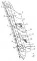
- an inventive motor vehicle bumper 10is shown according to a first preferred embodiment of the invention.
- the motor vehicle bumper 10is designed as a rear bumper and attached to a motor vehicle, of which only a portion of a vehicle body 12 and a portion of a tailgate 14 are shown.
- the bumper 10has a bumper outer part 16 and a bumper inner part 18.
- a deformation body 20is arranged below the bumper inner part 18.
- the deformation body 20is connected by means of merely indicated carrier 22 with the vehicle body 12.
- the bumper inner part 18consists of a base body 24 and a retaining strip 26.
- the retaining strip 26is releasably secured to the base body 24 by means of a latching connection.
- the locking connectionis formed by an integrally formed on the retaining strip 26 outer member 28 and an integrally connected to the base 24 inner member 30.
- Both the retaining strip 26 and the base body 24are made of plastic injection molding.
- the inner element 30is rod-shaped and has an outer surface which corresponds to a portion of a lateral surface of a circular cylinder. For weight and material savings, the inner member 30 has a U-shaped cross-section. Clipped onto the circular cylindrical lateral surface is a holding section 32 of the outer element 28, which engages around the inner element 30 in sections.
- a guide section 34Adjoining the holding section 32 is a guide section 34, which is curved in the opposite direction to the holding section 32.
- the guide section 34serves to introduce the inner member 30 when sliding the retaining strip 26 in the holding portion 32.
- a latching nose 36is formed between holding portion 32 and guide portion 34. In the illustrated latched state, the latching lug 36 holds the retaining strip 26 on the base body 24th
- the retaining strip 26clamps a front edge of the bumper outer part 16 in a recess extending parallel to the vehicle direction, which is defined on one side by a strip-shaped projection 38 and on the other side by clamping ribs 40. In this way, the front edge of the bumper outer member 16 is securely clamped in the retaining strip 26.
- the base body 24 of the bumper inner part 18 on a balcony-like projection 42which extends below the bumper outer part 16 in the loading edge and thereby the bumper outer part stabilized.
- the base body 24has a ribbed structure which is provided with recesses 44 for material and weight savings.
- a forceacts on the bumper outer part 16, which is indicated in Fig. 1 by means of an arrow F.
- the force Facts in the longitudinal direction of the vehicle and on the vehicle body 12.
- the latching connection between the outer element 28 of the retaining strip 26 and the inner element 30 of the base body 24is released.
- the front edge of the bumper outer part 16can move in the direction of the vehicle body 12 move.
- a Abweisschräge 50is formed, which causes the retaining strip 26 with the front edge of the Bumper outer part 16 forward and lower, in the illustration of FIG. 1 to the bottom left, is deflected.
- the base body 24 of the bumper inner member 18is formed so that between a front side 48 of the base body 24 and the Abweisschräge 50 of the vehicle body 12 remains a space that is large enough, a portion of the retaining strip 26th with the clamped therein portion of the bumper outer part 16.
- the front edge of the bumper outer member 16is deflected forward and below, so that they can not damage the vehicle body 12 in the event of an impact.
- the front edge of the bumper outer part 16 of.a portion of the vehicle body 12 derived by normally a Heckkläppensch for the tailgate 14 is located. This avoids that even after only a slight impact, the tailgate 14 can not be opened.
- the bumper outer part 16is connected in addition to the attachment to the bumper inner part 18 by means of further elements with the vehicle body and has an elasticity that the bumper outer part in the position shown in FIG. 1 with the base body 24 latched holding bar 26th is biased. Solves itself therefore in an impact by the action of the force F, the retaining strip 26 from the base body 24 and moves together with the loading edge region of the bumper outer part 16 in the space between the base body 24 and the Abweisschräge 50 of the vehicle body 12, the retaining strip 26 through the Preload of the bumper outer member 16 is moved back to the initial position shown in FIG. 1 after elimination of the force F.
- the bias of the bumper outer part 16is greater than a force required to engage the retaining strip 26 in the base body 24. After an impact, the bumper outer part automatically returns to its original position.
- FIG. 2shows the bumper inner member 18 obliquely from behind, i. from the side from which the front edge of the bumper outer part is inserted into the retaining strip 26.
- recognizable recesses 52are provided for the arrangement of fastening bolts for fastening the Stoßftician- mecanicteils.18 on the vehicle body 12.
- the retaining strip 26has for clamping the front edge of the bumper outer part of the clamping ribs 40, which are arranged parallel to each other and side by side. Since the retaining strip 26 is pivotably arranged on the base body 24 about a vehicle transverse direction, the base body 24 for stabilizing the bumper outer part in the region of the loading edge on the balcony-like projection 42.
- This balcony-like projection 42extends substantially over the entire width of the bumper inner part 18th
- the bumper inner part 18is shown from the front, ie visible is a side of the bumper inner part 18, which faces in the installed state of a vehicle body.
- the holding portions 32each consist of two mutually parallel and in the vehicle transverse direction from each other spaced strips of material which are bent in a circle-shaped manner.
- the two mutually parallel strips of materialdefine a recess between them.
- the base body 24starting from the arranged in the recesses 52 fasteners for attachment to the vehicle body first along the vehicle body then first away from this and finally parallel to the vehicle body and to run at a distance to this. As has been stated, this creates a space between the base body 24 and the vehicle body, in which the retaining strip 26 can move in the event of an impact together with a portion of the bumper outer part.
- FIG. 4a further embodiment of the motor vehicle bumper according to the invention is shown.
- the embodiment shown in Fig. 4differs from the embodiment shown in Figs. 1 to 3 by the design of a bumper inner part 54.
- the bumper inner part 54consists of a main body 56 and a retaining strip 58, in which a front edge of the bumper Outer part 16 is clamped.
- the retaining strip 58is connected by means of a latching connection with the base body 56.
- the latching connectionis formed on the side of the retaining strip 58 by an element 60 which is clamped between a rod-shaped element 62 and a strip-shaped element 64 of the base body 56.
- the element 60 of the retaining strip 58has a latching nose 66, which engages in a matching recess of the strip-shaped element 64.
- the element 60is wedge-shaped to facilitate insertion between the rod-shaped element 62 and the strip-like element 64.
- a spaceis formed, in which the retaining strip 58 can enter together with a portion of the bumper outer part 16 in the event of an impact.
Landscapes
- Engineering & Computer Science (AREA)
- Mechanical Engineering (AREA)
- Body Structure For Vehicles (AREA)
- Connection Of Plates (AREA)
Description
Translated fromGermanDie Erfindung betrifft einen Kraftfahrzeug-Stoßfänger nach dem Oberbegriff des Anspruchs 1. Die Erfindung betrifft auch ein Kraftfahrzeug mit einem erfindungsgemäßen Stoßfänger.The invention relates to a motor vehicle bumper according to the preamble of claim 1. The invention also relates to a motor vehicle with a bumper according to the invention.
Aus der
Aus der
Gesetzliche Vorschriften in einigen Ländern verlangen, dass Kraftfahrzeug-Stoßfänger einen Aufprall eines Fahrzeugs mit geringer Geschwindigkeit auf ein Hindernis vollständig und ohne Beschädigung abfangen bzw. dass ein Fahrzeug noch fahrtüchtig bleibt und beispielsweise die Funktion des Heckklappenschlosses erhalten bleibt. Aus Designgründen sollen solche Stoßfänger aber als integraler Bestandteil des Fahrzeugs erscheinen. Bekannte lösbare Stoßfängerbefestigungen weisen die lösbare Verbindung zwischen Fahrzeugkarosserie und Stoßfänger auf und sind damit auf enge Toleranzen der Fahrzeugkarosserie angewiesen.Legal regulations in some countries require that motor vehicle bumpers impact a vehicle at low speed on an obstacle completely and without Damage damage or that a vehicle still remains roadworthy and, for example, the function of the tailgate lock is maintained. For design reasons, however, such bumpers should appear as an integral part of the vehicle. Known releasable bumper fasteners have the detachable connection between the vehicle body and bumper and are thus dependent on tight tolerances of the vehicle body.
Mit der Erfindung soll ein Kraftfahrzeug-Stoßfänger geschaffen werden, der bei leichter Montierbarkeit eine Beschädigung der Fahrzeugkarosserie bei einem Aufprall mit geringer Geschwindigkeit verhindert.With the invention, a motor vehicle bumper to be created, which prevents easy mounting the vehicle body damage in a low-speed impact.
Erfindungsgemäß ist hierzu ein Kraftfahrzeug-Stoßfänger mit einem an-einer Fahrzeugkarosserie befestigbaren Stoßfänger-Innenteil und einem wenigstens abschnittsweise an dem Stoßfänger-Innenteil befestigten Stoßfänger-Außenteil vorgesehen, bei dem das Stoßfänger-Innenteil einen an der Fahrzeugkarosserie befestigten Grundkörper und eine mittels einer lösbaren Verbindung am Grundkörper befestigte Halteleiste aufweist, an der eine Kante des Stoßfänger-Außenteils befestigt ist, wobei die Verbindung der Halteleiste an dem Grundkörper durch eine Krafteinwirkung auf das Stoßfänger-Außenteil in Längsrichtung des Kraftfahrzeugs und auf die Fahrzeugkarosserie zu lösbar ist.According to the invention for this purpose, a motor vehicle bumper with an attachable to a vehicle body bumper inner part and at least partially secured to the bumper inner part bumper outer part is provided in which the bumper inner part attached to the vehicle body and a body by means of a detachable connection attached to the base body retaining strip, to which an edge of the bumper outer part is attached, wherein the connection of the retaining strip to the base body by a force on the bumper outer part in the longitudinal direction of the motor vehicle and on the vehicle body is to be solved.
Indem zur Befestigung der Kante des Stoßfänger-Außenteils eine Halteleiste vorgesehen ist, ist die lösbare Verbindung nicht von Toleranzen der Fahrzeugkarosserie abhängig. Darüber hinaus kann der komplette Stoßfänger einschließlich der lösbaren Verbindung als Einheit aus Stoßfänger-Innenteil und Stoßfänger-Außenteil an der Fahrzeugkarosserie befestigt werden. Besonders zweckmäßig ist das Vorsehen einer solchen lösbaren Verbindung im Bereich unterhalb einer Heckklappe oder eines Kofferraumdeckels eines Fahrzeugs. Da zwischen Stoßfänger und Fahrzeugkarosserie aus Designgründen kein sichtbarer Spalt bzw. ein möglichst kleiner Spalt vorhanden sein soll, besteht die Gefahr, dass eine Vorderkante des Stoßfänger-Außenteils auch bei einem leichten Aufprall die Fahrzeugkarosserie beaufschlagt und speziell den Bereich, in dem ein Schloss einer. Fahrzeugklappe angeordnet ist, verformt. Dadurch besteht die Gefahr, dass sich diese Klappe auch nach einem leichten Aufprall nicht mehr öffnen lässt. Indem sich die Halteleiste bei einem Fahrzeugaufprall vom Stoßfänger-Innenteil löst, erhält die Vorderkante des Stoßfänger-Außenteils Bewegungsfreiheit, so dass Beschädigungen der Fahrzeugkarosserie durch die Vorderkante des Stoßfänger-Außenteils verhindert werden können. Gegebenenfalls kann die Fahrzeugkarosserie geeignet gestaltet werden, um Bewegungsfreiheit für die Vorderkante zu schaffen.By providing a retaining strip for fastening the edge of the bumper outer part, the detachable connection is not dependent on tolerances of the vehicle body. In addition, the complete bumper including the releasable connection can be attached as a unit of bumper inner part and bumper outer part to the vehicle body. Particularly useful is the provision of such a releasable connection in the area below a tailgate or a trunk lid of a vehicle. Since there is no visible gap or smallest possible gap between bumper and vehicle body for design reasons, there is a risk that a front edge of the bumper outer part also in a light impact applied to the vehicle body and especially the area where a lock of a. Vehicle flap is arranged, deformed. There is a risk that this flap can not be opened even after a slight impact. By the retaining strip dissolves in a vehicle impact from the bumper inner part, receives the front edge of the bumper outer part freedom of movement, so that damage to the vehicle body can be prevented by the front edge of the bumper outer part. Optionally, the vehicle body may be designed to provide freedom of movement for the leading edge.
Erfindungsgemäß ist die lösbare Verbindung als Rastverbindung ausgebildet.According to the invention, the releasable connection is designed as a latching connection.
Durch diese Maßnahme kann das Stoßfänger-Außenteil mit der Halteleiste nach einem Fahrzeugaufprall wieder in den Grundkörper des Stoßfänger-Innenteils eingerastet werden. Darüber hinaus kann der Kraftfahrzeug-Stoßfänger einfach zusammengebaut werden.By this measure, the bumper outer part can be locked with the retaining strip after a vehicle collision back into the main body of the bumper inner part. In addition, the automobile bumper can be easily assembled.
In Weiterbildung der Erfindung weist die Rastverbindung wenigstens ein in Fahrzeugquerrichtung verlaufendes stabförmiges inneres Element und wenigstens ein das stabförmige Element abschnittsweise umgreifendes äußeres Element auf.In a further development of the invention, the latching connection has at least one extending in the vehicle transverse direction rod-shaped inner element and at least one rod-shaped element in sections encompassing outer element.
Mittels eines stabförmigen Elements, das in Fahrzeugquerrichtung verläuft, kann eine gewisse Toleranz in Fahrzeugquerrichtung geschaffen werden, die einen Zusammenbau des Kraftfahrzeug-Stoßfängers erleichtert. Auch das Wiedereinrasten der Rastverbindung nach einem Aufprall wird dadurch erleichtert.By means of a rod-shaped element which extends in the vehicle transverse direction, a certain tolerance in the vehicle transverse direction can be created, which facilitates assembly of the motor vehicle bumper. Also, the re-engagement of the locking connection after an impact is facilitated.
In Weiterbildung der Erfindung weist das stabförmige innere Element eine kreiszylinderabschnittförmige Außenfläche auf, die abschnittsweise einer Kreiszylindermantelfläche entspricht.In a further development of the invention, the rod-shaped inner element has a circular cylindrical section-shaped outer surface, which corresponds in sections to a circular cylinder jacket surface.
Auf diese Weise kann die Halteleiste eine Schwenkbewegung um eine Fahrzeugquerrichtung ausführen. Ein sehr leichter Aufprall, beispielsweise ein sogenannter Parkrempler, kann dadurch möglicherweise durch eine Schwenkbewegung der Halteleiste abgefangen werden und führt nicht zu einem Lösen der Rastverbindung. Im Hinblick auf eine Material- und Gewichtsersparnis kann das stabförmige innere Element in Fahrzeugquerrichtung einen U-förmigen Querschnitt aufweisen.In this way, the retaining strip can perform a pivoting movement about a vehicle transverse direction. A very slight impact, for example a so-called parking bump, can possibly be intercepted by a pivoting movement of the retaining strip and does not lead to a release of the locking connection. With regard to saving material and weight, the rod-shaped inner element in the vehicle transverse direction may have a U-shaped cross section.
In Weiterbildung der Erfindung weist das äußere Element einen das stabförmige innere Element abschnittsweise umgreifenden Halteabschnitt sowie einen Führungsabschnitt auf, mittels dem beim Bewegen des äußeren Elements auf das innere Element zu das stabförmige Element in den Halteabschnitt eingeführt wird.In a further development of the invention, the outer element has a holding portion which surrounds the rod-shaped inner element in sections and a guide section, by means of which the rod-shaped element is introduced into the holding section when the inner element is moved onto the inner element.
Durch diese Maßnahmen wird der Zusammenbau des Kraftfahrzeug-Stoßfängers sowie das Wiedereinrasten der Rastverbindung nach einem Aufprall erleichtert.By these measures, the assembly of the motor vehicle bumper and the re-engagement of the locking connection is facilitated after an impact.
In Weiterbildung der Erfindung weist das äußere Element am Übergang zwischen Halteabschnitt und Führungsabschnitt eine Rastnase auf.In a further development of the invention, the outer element at the transition between holding portion and guide portion on a locking lug.
Trotz leichter Einführbarkeit des Halteabschnitts auf das stabförmige Element wird die Halteleiste im eingerasteten Zustand durch die Rastnase sicher am inneren Element gehalten.Despite easier insertability of the holding portion on the rod-shaped element, the retaining strip is held securely in the locked state by the latch on the inner element.
In Weiterbildung der Erfindung ist das Stoßfänger-Außenteil in die mit dem Stoßfänger-Innenteil verbundene Position vorgespannt.In a further development of the invention, the bumper outer part is biased in the connected to the bumper inner part position.
Durch diese Maßnahme kehrt das Außenteil dann, wenn es sich mit der Halteleiste vom Grundkörper des Innenteils bei einem Aufprall gelöst hat, selbsttätig in die Ausgangsposition zurück, wenn das Stoßfänger-Außenteil wieder frei ist, beispielsweise nach einem leichten Aufprall. Die Vorspannung des Stoßfänger-Außenteils in die mit dem Stoßfänger-Innenteil verbundene Position ist größer als eine zum Einrasten der Rastverbindung erforderliche Kraft.By this measure, the outer part, when it has been solved with the retaining strip from the main body of the inner part in an impact, automatically returns to the starting position when the bumper outer part is free again, for example, after a slight impact. The bias of the bumper outer part in the connected to the bumper inner part position is greater than a force required to engage the latching connection.
In Weiterbildung der Erfindung weist das Stoßfänger-Innenteil eine Rippenstruktur auf.In a further development of the invention, the bumper inner part has a rib structure.
Dadurch kann eine Material- und Gewichtseinsparung mit sehr hoher Steifigkeit verbunden werden.This can be combined with a very high rigidity material and weight savings.
In Weiterbildung der Erfindung verläuft das Stoßfänger-Innenteil ausgehend von ersten Befestigungsmitteln zur Befestigung an der Fahrzeugkarosserie in Richtung auf eine Ladekante des Stoßfänger-Außenteils zu im wesentlichen entlang der Fahrzeugkarosserie und weist unterhalb des Bereichs der Ladekante wenigstens einen balkonartigen Vorsprung auf, der sich in Fahrzeuglängsrichtung erstreckt.In a further development of the invention, the bumper inner part extends starting from first attachment means for attachment to the vehicle body in the direction of a loading edge of the bumper outer part to substantially along the vehicle body and has below the region of the sill at least one balcony-like projection, extending in the vehicle longitudinal direction extends.
Dadurch wird Raum für eine Verformung des Stoßfänger-Außenteils unterhalb des balkonartigen Vorsprungs geschaffen. Trotzdem wird mittels des balkonartigen Vorsprungs ein Ladekantenbereich stabilisiert. Mehrere, balkonartige Vorsprünge können in Fahrzeugquerrichtung nebeneinander angeordnet werden.This creates room for deformation of the bumper outer part below the balcony-like projection. Nevertheless, a loading edge region is stabilized by means of the balcony-like projection. Several, balcony-like projections can be arranged side by side in the vehicle transverse direction.
In Weiterbildung der Erfindung ist die Halteleiste als Klemmleiste ausgebildet und ist mit in Fahrzeuglängsrichtung verlaufenden und im wesentlichen senkrecht zur Fahrzeugquerrichtung angeordneten Klemmrippen versehen.In a further development of the invention, the retaining strip is designed as a terminal block and is provided with running in the vehicle longitudinal direction and arranged substantially perpendicular to the vehicle transverse direction clamping ribs.
Mittels einer solchen Klemmleiste wird ein sicherer Klemmsitz der Kante des Stoßfänger-Außenteils in der Halteleiste erreicht. Gegenüber einer vollflächigen Rampe zum Einklemmen der Kante des Stoßfänger-Außenteils weisen Klemmrippen den Vorteil einer Materialersparnis sowie einer leichteren Anpassbarkeit in bezug auf Toleranzen auf.By means of such a terminal strip a secure clamping seat of the edge of the bumper outer part is achieved in the retaining strip. Compared to a full-surface ramp for clamping the edge of the bumper outer part clamping ribs have the advantage of a material savings and easier adaptability in terms of tolerances.
Das der Erfindung zugrundeliegende Problem wird auch durch ein Kraftfahrzeug mit einem erfindungsgemäßen Stoßfänger gelöst, bei dem die Fahrzeugkarosserie in einem der Halteleiste zugewandten Bereich eine Abweisschräge für die Halteleiste aufweist.The problem underlying the invention is also solved by a motor vehicle with a bumper according to the invention, in which the vehicle body in a region facing the retaining strip has a deflection slope for the retaining strip.
Auf diese Weise kann bei einem Aufprall die vom Grundkörper gelöste Halteleiste und somit das Stoßfänger-Außenteil geführt werden. Beispielsweise verläuft die Abweisschräge im Falle einer Heckklappe nach vorne unten, so dass die Vorderkante des Stoßfänger-Außenteils bei einem Aufprall vom Klappenschlossbereich weggeführt wird. Durch die Abweisschräge wird für den gleichen Verformungsweg der Vorderkante weniger Bauraum benötigt, als wenn sich die Vorderkante ausschließlich in Fahrzeuglängsrichtung bewegen würde.In this way, in a collision, the dissolved from the body holding bar and thus the bumper outer part can be performed. For example, in the case of a tailgate, the deflection slope extends forwards and downwards, so that the front edge of the bumper outer part is guided away from the flap lock area in the event of an impact. Due to the deflection slope, less installation space is required for the same deformation path of the front edge than if the front edge only moved in the vehicle longitudinal direction.
In Weiterbildung der Erfindung ist unterhalb des Stoßfänger-Innenteils ein Verformungskörper innerhalb des Stoßfänger-Außenteils angeordnet und an der Fahrzeugkarosserie befestigt.In a further development of the invention, a deformation element is arranged inside the bumper outer part below the bumper inner part and fastened to the vehicle body.
Eine solche Aufteilung in Verformungskörper und Innenteil ermöglicht eine an die Funktion angepasste Materialauswahl. Beispielsweise kann das eine Haltefunktion ausübende Innenteil aus Kunststoff, der zur Energieaufnahme vorgesehene Verformungskörper aus Aluminium aufgebaut werden.Such a division into deformation body and inner part enables a material selection adapted to the function. For example, the holding function performing inner part made of plastic, which are provided for energy absorption deformation body made of aluminum.
Weitere Merkmale und Vorteile der Erfindung ergeben sich aus den Ansprüchen und der folgenden Beschreibung bevorzugter Ausführungsformen der Erfindung im Zusammenhang mit den Zeichnungen. In den Zeichnungen zeigen:
- Fig. 1
- eine abschnittsweise Schnittansicht eines erfindungsgemäßen Kraftfahrzeug-Stoßfängers gemäß einer ersten Ausführungsform,
- Fig. 2
- eine perspektivische Ansicht des Innenteils des Kraftfahrzeug-Stoßfängers der Fig. 1,
- Fig. 3
- eine weitere perspektivische Ansicht des Innenteils des Kraftfahrzeug-Stoßfängers der Fig. 1 und
- Fig. 4
- eine abschnittsweise Schnittansicht einer weiteren Ausführungsform des erfindungsgemäßen Kraftfahrzeug-Stoßfängers.
- Fig. 1
- a sectional sectional view of a motor vehicle bumper according to the invention according to a first embodiment,
- Fig. 2
- 1 is a perspective view of the inner part of the motor vehicle bumper of FIG. 1,
- Fig. 3
- a further perspective view of the inner part of the motor vehicle bumper of Fig. 1 and
- Fig. 4
- a sectional sectional view of another embodiment of the motor vehicle bumper according to the invention.
In der Darstellung der Fig. 1 ist ein erfindungsgemäßer Kraftfahrzeug-Stoßfänger 10 gemäß einer ersten bevorzugten Ausführungsform der Erfindung dargestellt. Der Kraftfahrzeug-Stoßfänger 10 ist als Heckstoßfänger ausgebildet und an einem Kraftfahrzeug angebracht, von dem lediglich ein Abschnitt einer Fahrzeugkarosserie 12 sowie ein Abschnitt einer Heckklappe 14 dargestellt sind. Der Stoßfänger 10 weist ein Stoßfänger-Außenteil 16 sowie ein Stoßfänger-Innenteil 18 auf. In einem Raum zwischen dem Stoßfänger-Außenteil 16 und der Fahrzeugkarosserie 12 ist unterhalb des Stoßfänger-Innenteils 18 ein Verformungskörper 20 angeordnet. Der Verformungskörper 20 ist mittels lediglich angedeuteter Träger 22 mit der Fahrzeugkarosserie 12 verbunden.In the illustration of Fig. 1, an inventive motor vehicle bumper 10 is shown according to a first preferred embodiment of the invention. The motor vehicle bumper 10 is designed as a rear bumper and attached to a motor vehicle, of which only a portion of a
Das Stoßfänger-Innenteil 18 besteht aus einem Grundkörper 24 und einer Halteleiste 26. Die Halteleiste 26 ist mittels einer Rastverbindung lösbar an dem Grundkörper 24 befestigt. Die Rastverbindung wird durch ein einstückig an der Halteleiste 26 ausgebildetes äußeres Element 28 und ein einstückig mit dem Grundkörper 24 verbundenes inneres Element 30 gebildet. Sowohl die Halteleiste 26 als auch der Grundkörper 24 bestehen aus Kunststoffspritzguss. Das innere Elemente 30 ist stabförmig ausgebildet und weist eine Außenfläche auf, die einem Abschnitt einer Mantelfläche eines Kreiszylinders entspricht. Zur Gewichts- und Materialeinsparung hat das innere Element 30 einen U-förmigen Querschnitt. Auf die kreiszylinderförmige Mantelfläche aufgeklipst ist ein Halteabschnitt 32 des äußeren Elements 28, der das innere Element 30 abschnittsweise umgreift. An den Halteabschnitt 32 schließt sich ein Führungsabschnitt 34 an, der entgegen dem Halteabschnitt 32 gekrümmt ist. Der Führungsabschnitt 34 dient dazu, das innere Element 30 beim Aufschieben der Halteleiste 26 in den Halteabschnitt 32 einzuführen. Zwischen Halteabschnitt 32 und Führungsabschnitt 34 ist eine Rastnase 36 ausgebildet. Im dargestellten eingerasteten Zustand hält die Rastnase 36 die Halteleiste 26 an dem Grundkörper 24.The bumper
Die Halteleiste 26 klemmt eine Vorderkante des Stoßfänger-Außenteils 16 in einer parallel zur Fahrzeugrichtung verlaufenden Ausnehmung ein, die auf der einen Seite durch einen leistenförmigen Vorsprung 38 und auf der anderen Seite durch Klemmrippen 40 definiert ist. Auf diese Weise wird die Vorderkante des Stoßfänger-Außenteils 16 sicher in der Halteleiste 26 eingeklemmt.The retaining
Unterhalb der Heckklappe 14 befindet sich ein Ladekantenbereich des Stoßfänger-Außenteils 16. Um diesen Ladekantenbereich zu stabilisieren, weist der Grundkörper 24 des Stoßfänger-Innenteils 18 einen balkonartigen Vorsprung 42 auf, der sich unterhalb des Stoßfänger-Außenteils 16 im Bereich der Ladekante erstreckt und dadurch das Stoßfänger-Außenteil stabilisiert. Der Grundkörper 24 weist eine Rippenstruktur auf, die für eine Material- und Gewichtsersparnis mit Ausnehmungen 44 versehen ist. Eine Befestigung des Grundkörpers 24 an der Fahrzeugkarosserie 12 erfolgt mittels Befestigungsbolzen 46, die in der Fig. 1 lediglich schematisch angedeutet sind.Below the
Im Falle eines leichten Heckaufpralls wirkt eine Kraft auf das Stoßfänger-Außenteil 16, die in der Fig. 1 mittels eines Pfeils F angedeutet ist. Die Kraft F wirkt in Längsrichtung des Fahrzeugs und auf die Fahrzeugkarosserie 12 zu. Durch die Einwirkung der Kraft F auf das Stoßfänger-Außenteil 16 löst sich die Rastverbindung zwischen dem äußeren Element 28 der Halteleiste 26 und dem inneren Element 30 des Grundkörpers 24. Infolgedessen kann sich die Vorderkante des Stoßfänger-Außenteils 16 in Richtung auf die Fahrzeugkarosserie 12 zu bewegen. An der Fahrzeugkarosserie 12 ist eine Abweisschräge 50 ausgebildet, die dazu führt, dass die Halteleiste 26 mit der Vorderkante des Stoßfänger-Außenteils 16 nach vorne unten, in der Darstellung der Fig. 1 nach unten links, abgelenkt wird. Um diese Ablenkbewegung der Halteleiste 26 zu ermöglichen, ist der Grundkörper 24 des Stoßfänger-Innenteils 18 so ausgebildet, dass zwischen einer Vorderseite 48 des Grundkörpers 24 und der Abweisschräge 50 der Fahrzeugkarosserie 12 ein Raum verbleibt, der groß genug ist, einen Abschnitt der Halteleiste 26 mit dem darin eingeklemmten Abschnitt des Stoßfänger-Außenteils 16 aufzunehmen. Durch die ausknöpfbare Halteleiste 26 und die Abweisschräge 50 wird die Vorderkante des Stoßfänger-Außenteils 16 nach vorne unten abgelenkt, so dass sie im Falle eines Aufpralls die Fahrzeugkarosserie 12 nicht beschädigen kann. Insbesondere wird die Vorderkante des Stoßfänger-Außenteils 16 von. einem Bereich der Fahrzeugkarosserie 12 abgeleitet, indem sich normalerweise ein Heckkläppenschloss für die Heckklappe 14 befindet. Dadurch wird vermieden, dass sich auch nach einem nur leichten Aufprall die Heckklappe 14 nicht mehr öffnen lässt.In the case of a slight rear impact, a force acts on the bumper
Das Stoßfänger-Außenteil 16 ist neben der Befestigung am Stoßfänger-Innenteil 18 mittels weiterer Elemente so mit der Fahrzeugkarosserie verbunden und weist eine Elastizität auf, dass das Stoßfänger-Außenteil in die in der Fig. 1 dargestellten Lage mit in den Grundkörper 24 eingerasteter Halteleiste 26 vorgespannt ist. Löst sich daher bei einem Aufprall durch Einwirkung der Kraft F die Halteleiste 26 vom Grundkörper 24 und bewegt sich zusammen mit dem Ladekantenbereich des Stoßfänger-Außenteils 16 in den Raum zwischen dem Grundkörper 24 und der Abweisschräge 50 der Fahrzeugkarosserie 12, wird die Halteleiste 26 durch die Vorspannung des Stoßfänger-Außenteils 16 nach Wegfall der Kraft F wieder in die in der Fig. 1 dargestellte Ausgangsstellung zurückbewegt. Die Vorspannung des Stoßfänger-Außenteils 16 ist dabei größer als eine zum Einrasten der Halteleiste 26 in den Grundkörper 24 erforderliche Kraft. Nach einem Aufprall kehrt das Stoßfänger-Außenteil damit selbsttätig in die Ausgangsstellung zurück.The bumper
Die perspektivische Ansicht der Fig. 2 zeigt das Stoßfänger-Innenteil 18 von schräg hinten, d.h. von der Seite aus, von der die Vorderkante des Stoßfänger-Außenteils in die Halteleiste 26 eingeschoben wird. In der Darstellung der Fig. 2 gut zu erkennen, ist die rippenförmige Struktur des Grundkörpers 24 des Stoßfänger-Innenteils 18. Dadurch wird eine hohe Steifigkeit des Grundkörpers 24 erreicht. In der Fig. 2 erkennbare Ausnehmungen 52 sind für die Anordnung von Befestigungsbolzen zur Befestigung des Stoßfänger-Innenteils.18 an der Fahrzeugkarosserie 12 vorgesehen.The perspective view of Fig. 2 shows the bumper
Ebenfalls zu erkennen sind insgesamt fünf stabförmige innere Elemente 30 des Grundkörpers 24, die jeweils von einem Halteabschnitt 32 der Halteleiste 26 umgriffen werden. Der Halteabschnitt 32 ist in der Fig. 2 nicht zu erkennen. Zu erkennen sind dagegen die jeweiligen Führungsabschnitte 34 sowie die jeweiligen Rastnasen 36 der äußeren Elemente 28 der Rastverbindung zwischen Halteleiste 26 und Grundkörper 24.Also visible are a total of five rod-shaped
Die Halteleiste 26 weist zum Einklemmen der Vorderkante des Stoßfänger-Außenteils die Klemmrippen 40 auf, die parallel zueinander und nebeneinander angeordnet sind. Da die Halteleiste 26 an dem Grundkörper 24 um eine Fahrzeugquerrichtung verschwenkbar angeordnet ist, weist der Grundkörper 24 zur Stabilisierung des Stoßfänger-Außenteils im Bereich der Ladekante den balkonartigen Vorsprung 42 auf. Dieser balkonartige Vorsprung 42 erstreckt sich im wesentlichen über die gesamte Breite des Stoßfänger-Innenteils 18.The retaining
In der perspektivischen Ansicht der Fig. 3 ist das Stoßfänger-Innenteil 18 von vorne gezeigt, d.h. sichtbar ist eine Seite des Stoßfänger-Innenteils 18, die im eingebauten Zustand einer Fahrzeugkarosserie zugewandt ist. In dieser Ansicht sind nun die jeweiligen Halteabschnitte 32 der äußeren Elemente der Rastverbindung zwischen Halteleiste 26 und Grundkörper 24 zu erkennen. Die Halteabschnitte 32 bestehen jeweils aus zwei parallel zueinander verlaufenden und in Fahrzeugquerrichtung voneinander beabstandeten Materialstreifen, die kreisabschnittsförmig gebogen sind. Die zwei parallel zueinander verlaufenden Materialstreifen definieren zwischen sich eine Ausnehmung. Indem anstelle von Vollmaterial der Halteabschnitt aus zwei parallelen Materialstreifen ausgebildet wird, kann einerseits Gewicht eingespart werden, andererseits kann eine Federwirkung des Halteabschnitts durch Veränderung der Breite der Materialstreifen abgestimmt werden.In the perspective view of FIG. 3, the bumper
Wie aus den Darstellungen der Fig. 1 und der Fig. 3 zu entnehmen ist, verläuft der Grundkörper 24 ausgehend von den in den Ausnehmungen 52 angeordneten Befestigungsmitteln zur Befestigung an der Fahrzeugkarosserie zunächst entlang der Fahrzeugkarosserie um dann zunächst von dieser weg und schließlich parallel zur Fahrzeugkarosserie und im Abstand zu dieser zu verlaufen. Wie ausgeführt wurde, wird dadurch ein Raum zwischen Grundkörper 24 und Fahrzeugkarosserie geschaffen, in den sich die Halteleiste 26 im Falle eines Aufpralls zusammen mit einem Abschnitt des Stoßfänger-Außenteils hineinbewegen kann.As can be seen from the illustrations of Fig. 1 and Fig. 3, the
In der abschnittsweisen Schnittansicht der Fig. 4 ist eine weitere Ausführungsform des erfindungsgemäßen Kraftfahrzeug-Stoßfängers dargestellt. Die in Fig. 4 dargestellte Ausführungsform unterscheidet sich von der in den Fig. 1 bis 3 gezeigten Ausführungsform durch die Gestaltung eines Stoßfänger-Innenteils 54. Das Stoßfänger-Innenteil 54 besteht aus einem Grundkörper 56 und einer Halteleiste 58, in die eine Vorderkante des Stoßfänger-Außenteils 16 eingeklemmt ist. Die Halteleiste 58 ist mittels einer Rastverbindung mit dem Grundkörper 56 verbunden. Die Rastverbindung wird auf Seiten der Halteleiste 58 durch ein Element 60 gebildet, das zwischen ein stabförmiges Element 62 und ein leistenförmiges Element 64 des Grundkörpers 56 eingeklemmt wird. Das Element 60 der Halteleiste 58 weist eine Rastnase 66 auf, die in eine passende Ausnehmung des leistenförmigen Elements 64 eingreift. Das Element 60 ist dabei keilförmig ausgebildet, um das Einführen zwischen das stabförmige Element 62 und das leistenartige Element 64 zu erleichtern. Zwischen einer der Fahrzeugkarosserie 12 zugewandten Seite 68 des Grundkörpers 56 und der Fahrzeugkarosserie 12 ist ein Raum gebildet, in den die Halteleiste 58 im Falle eines Aufpralls zusammen mit einem Abschnitt des Stoßfänger-Außenteils 16 einlaufen kann.In the sectional sectional view of FIG. 4, a further embodiment of the motor vehicle bumper according to the invention is shown. The embodiment shown in Fig. 4 differs from the embodiment shown in Figs. 1 to 3 by the design of a bumper inner part 54. The bumper inner part 54 consists of a
Claims (12)
- A motor-vehicle bumper having a bumper inner portion (18; 54), which can be secured to a vehicle body (12), and a bumper outer portion (16), which is secured at least in sections to the bumper inner portion (18; 54), with the bumper inner portion (18; 54) having a base body (24; 56), which is secured to the vehicle body (12), and a holding strip (26; 58) which is secured to the base body (24; 56) by means of a releasable connection and to which an edge of the bumper outer portion (16) is secured, and the connection of the holding strip (26; 58) on the base body (24; 56) being releasable by means of an action of force on the bumper outer portion (16), with the connection of the holding strip (26; 58) to the base body (24; 56) being releasable by means of an action of force on the bumper outer portion (16) in the longitudinal direction of the motor vehicle and towards the vehicle body (12), and the holding strip (26; 58) being formed as a clamping strip,characterised in that the releasable connection is formed as a latching connection.
- A motor-vehicle bumper according to claim 1,characterised in that the latching connection has at least one bar-shaped inner element (30) extending in the transverse direction of the vehicle and at least one outer element (28) embracing the bar-shaped element (30) in sections.
- A motor-vehicle bumper according to claim 2,characterised in that the bar-shaped inner element (30) has an outer surface that corresponds in sections to a circular cylinder lateral surface.
- A motor-vehicle bumper according to claim 2 or 3,characterised in that the outer element (28) has a holding section (32) that embraces the bar-shaped inner element (30) in sections and also a guiding section (34) by means of which in the event of the movement of the outer element (28) towards the inner element (30) the bar-shaped element (30) is introduced into the holding section (32).
- A motor-vehicle bumper according to one of the preceding claims,characterised in that the outer element (28) has a latching lug (36) at the transition between the holding section (32) and the guiding section (34).
- A motor-vehicle bumper according to one of the preceding claims,characterised in that the bumper outer portion (16) is pre-tensioned into the position connected with the bumper inner portion (18).
- A motor-vehicle bumper according to one of the preceding claims,characterised in that the bumper inner portion (18) has a ribbed structure.
- A motor-vehicle bumper according to one of the preceding claims,characterised in that the bumper inner portion (18) has at least one balcony-like projection (42) below a region of a loading edge.
- A motor-vehicle bumper according to one of the preceding claims,characterised in that the clamping strip (26; 58) is provided with clamping ribs (40) which extend in the longitudinal direction of the vehicle and are arranged substantially perpendicularly to the transverse direction of the vehicle.
- A motor vehicle having a bumper according to one of the preceding claims,characterised in that the vehicle body (12) has a deflector slope (50) for the holding strip (26; 58) in a region facing the holding strip (26; 58).
- A motor vehicle according to claim 10,characterised in that formed between the base body (24) of the bumper inner portion (18) and the deflector slope (50) of the vehicle body (12) there is a space into which the holding strip (26) can be moved with a section of the bumper outer portion (16).
- A motor vehicle according to claim 10 or 11,characterised in that below the bumper inner portion (18) a deformation body (20) is arranged inside the bumper outer portion (16) and is secured to the vehicle body (12).
Applications Claiming Priority (2)
| Application Number | Priority Date | Filing Date | Title |
|---|---|---|---|
| DE10156893ADE10156893B4 (en) | 2001-11-20 | 2001-11-20 | Motor vehicle with a bumper |
| DE10156893 | 2001-11-20 |
Publications (3)
| Publication Number | Publication Date |
|---|---|
| EP1312513A2 EP1312513A2 (en) | 2003-05-21 |
| EP1312513A3 EP1312513A3 (en) | 2004-06-09 |
| EP1312513B1true EP1312513B1 (en) | 2007-10-17 |
Family
ID=7706324
Family Applications (1)
| Application Number | Title | Priority Date | Filing Date |
|---|---|---|---|
| EP02025803AExpired - LifetimeEP1312513B1 (en) | 2001-11-20 | 2002-11-18 | Vehicle bumper |
Country Status (4)
| Country | Link |
|---|---|
| US (1) | US6698808B2 (en) |
| EP (1) | EP1312513B1 (en) |
| DE (1) | DE10156893B4 (en) |
| ES (1) | ES2295278T3 (en) |
Families Citing this family (21)
| Publication number | Priority date | Publication date | Assignee | Title |
|---|---|---|---|---|
| DE10156892A1 (en)* | 2001-11-20 | 2003-05-28 | Daimler Chrysler Ag | Motor vehicle bumper and motor vehicle |
| FR2858798B1 (en)* | 2003-08-11 | 2006-02-03 | Plastic Omnium Cie | TECHNICAL FRONT PANEL FRONT OF A MOTOR VEHICLE, TECHNICAL FRONT PANEL AND COOLING MODULE SUPPORT PROVIDED WITH SUCH A TRAVERSE |
| US20050190573A1 (en)* | 2004-02-27 | 2005-09-01 | Schwab Leo F. | Releaseable fastening device |
| KR20050117905A (en)* | 2004-06-11 | 2005-12-15 | 현대모비스 주식회사 | Structure of mounting bumper cover in a carrier |
| DE102004057173A1 (en)* | 2004-11-26 | 2006-06-01 | Audi Ag | Motor vehicle with a bumper |
| DE102005027178A1 (en)* | 2005-06-13 | 2006-12-14 | GM Global Technology Operations, Inc., Detroit | Front structure for motor vehicle, has bumper with outer shell part lying on upper side of support, where part includes wall that points in driving direction and is spaced from support |
| US7489453B2 (en)* | 2005-11-15 | 2009-02-10 | Visteon Global Technologies, Inc. | Side emitting near field lens |
| JP2007290689A (en)* | 2006-03-29 | 2007-11-08 | Denso Corp | Collision detecting means |
| JP4203079B2 (en)* | 2006-04-24 | 2008-12-24 | 本田技研工業株式会社 | Bumper structure for vehicles |
| DE102006030505B4 (en)* | 2006-07-01 | 2014-04-03 | Audi Ag | Device for connecting a bumper cover to a body |
| DE102006032597A1 (en) | 2006-07-14 | 2008-01-17 | Dr.Ing.H.C. F. Porsche Ag | Fastening device for an attachment of a motor vehicle |
| US7682218B2 (en)* | 2006-09-20 | 2010-03-23 | Mattel, Inc. | Toy vehicle and launcher |
| US7866716B2 (en) | 2008-04-08 | 2011-01-11 | Flex-N-Gate Corporation | Energy absorber for vehicle |
| US8025322B2 (en)* | 2008-06-20 | 2011-09-27 | Toyota Motor Engineering & Manufacturing North America, Inc. | Bumper cover attachment method |
| DE102008045893B4 (en)* | 2008-09-04 | 2014-03-13 | Audi Ag | Bumper for a motor vehicle |
| DE102008059324B4 (en)* | 2008-11-27 | 2022-09-01 | Dr. Ing. H.C. F. Porsche Aktiengesellschaft | Motor vehicle with a bumper arrangement |
| DE102012015001B4 (en) | 2012-07-28 | 2019-03-28 | Volkswagen Aktiengesellschaft | Arrangement for mounting a bumper cover on the body of a vehicle and vehicle to it |
| US10065587B2 (en) | 2015-11-23 | 2018-09-04 | Flex|N|Gate Corporation | Multi-layer energy absorber |
| JP7059500B2 (en)* | 2019-05-30 | 2022-04-26 | 株式会社ニフコ | Bumper mounting retainer |
| DE102019209982A1 (en) | 2019-07-08 | 2021-01-14 | Ford Global Technologies, Llc | Rear assembly for a motor vehicle and motor vehicle |
| DE202019106700U1 (en)* | 2019-12-02 | 2021-03-03 | Rehau Ag + Co | Front bumper lining part of a motor vehicle |
Family Cites Families (18)
| Publication number | Priority date | Publication date | Assignee | Title |
|---|---|---|---|---|
| US3715138A (en)* | 1971-01-22 | 1973-02-06 | M Finkle | Resilient frangible bumper guard |
| US3907352A (en)* | 1974-02-12 | 1975-09-23 | William H Spain | Break away front truck bumper |
| US4095831A (en)* | 1975-12-09 | 1978-06-20 | Nissan Motor Company, Limited | Vehicle bumper device |
| US4225167A (en)* | 1978-03-06 | 1980-09-30 | Buettner Carl F | Vehicle bumpers with collapsible parts |
| US4685712A (en)* | 1986-09-25 | 1987-08-11 | Chrysler Motors Corporation | Spring mounted molding for a vehicle |
| US4753467A (en)* | 1987-02-17 | 1988-06-28 | Chrysler Motors Corporation | Movable molding for a vehicle |
| US4877279A (en)* | 1987-09-03 | 1989-10-31 | General Motors Corp. | Stroking fascia for vehicle energy absorbing bumper systems |
| DE3817842A1 (en)* | 1988-05-26 | 1989-12-07 | Audi Ag | BUMPER ARRANGEMENT ON A MOTOR VEHICLE |
| FR2634703B1 (en)* | 1988-07-29 | 1991-12-13 | Renault | DEVICE FOR FIXING A BUMPER FOR MOTOR VEHICLES |
| US5022692A (en)* | 1990-05-29 | 1991-06-11 | Chrysler Corporation | Spring mounted molding for a vehicle |
| GB9302989D0 (en)* | 1993-02-15 | 1993-03-31 | Nissan Europ Tech Centre | Vehicle bumper assembly |
| US5580109A (en)* | 1994-08-01 | 1996-12-03 | Chrysler Corporation | Bumper fascia support, bumper fascia support and reinforcement assembly, and bumper assembly |
| DE19708118A1 (en)* | 1997-02-28 | 1998-09-03 | Dynamit Nobel Kunststoff Gmbh | Fastening system for integrated bumpers |
| DE19736755B4 (en)* | 1997-08-23 | 2006-03-30 | Volkswagen Ag | Fastening arrangement for a stretched profile part on a support, in particular for a lateral bumper cover on a body-side support profile |
| JP4097327B2 (en)* | 1998-08-06 | 2008-06-11 | ポップリベット・ファスナー株式会社 | Bumper retaining clip |
| JP4066061B2 (en)* | 1999-05-27 | 2008-03-26 | 関東自動車工業株式会社 | Bumper mounting structure |
| DE10013427C2 (en)* | 2000-03-17 | 2003-02-20 | Daimler Chrysler Ag | motor vehicle front |
| DE10156892A1 (en)* | 2001-11-20 | 2003-05-28 | Daimler Chrysler Ag | Motor vehicle bumper and motor vehicle |
- 2001
- 2001-11-20DEDE10156893Apatent/DE10156893B4/ennot_activeExpired - Fee Related
- 2002
- 2002-11-15USUS10/298,166patent/US6698808B2/ennot_activeExpired - Lifetime
- 2002-11-18EPEP02025803Apatent/EP1312513B1/ennot_activeExpired - Lifetime
- 2002-11-18ESES02025803Tpatent/ES2295278T3/ennot_activeExpired - Lifetime
Also Published As
| Publication number | Publication date |
|---|---|
| EP1312513A2 (en) | 2003-05-21 |
| US6698808B2 (en) | 2004-03-02 |
| DE10156893A1 (en) | 2003-05-28 |
| EP1312513A3 (en) | 2004-06-09 |
| ES2295278T3 (en) | 2008-04-16 |
| US20030160464A1 (en) | 2003-08-28 |
| DE10156893B4 (en) | 2008-10-02 |
Similar Documents
| Publication | Publication Date | Title |
|---|---|---|
| EP1312513B1 (en) | Vehicle bumper | |
| DE69902324T2 (en) | Device for attaching the side legs of a bumper to a vehicle body fender | |
| DE60212246T2 (en) | Group of two body parts which are joined edge to edge and body part of such a group of components | |
| DE19912267C2 (en) | Locking device for connecting two components of a motor vehicle | |
| EP1663700B1 (en) | Memory device for a rail longitudinal guide for a motor vehicle seat | |
| EP1093429A1 (en) | Instrument panel carrier arrangement in the body of a motor vehicle and instrument panel carrier | |
| WO2009012840A1 (en) | Locking device for the bonnet of a motor vehicle | |
| DE102018210094A1 (en) | Arrangement of a holder on a structural part of a motor vehicle, in particular on a bumper cross member of a motor vehicle | |
| DE102018211974B4 (en) | Bumper assembly and filler | |
| DE102022113406B3 (en) | Side skirts for a motor vehicle body | |
| EP1070641B1 (en) | Height adjusting device for a vehicle seat belt | |
| EP1316479A2 (en) | Bumper support and bumper for vehicles | |
| DE10206780B4 (en) | Fastening device for a child seat | |
| EP1348585B1 (en) | Displaceable panel for vehicle roof and sliding roof module | |
| DE19506936C1 (en) | Car chassis structure with high=level floor | |
| DE10040649C1 (en) | Open automobile roll bar assembly has cassette housing with U-profile side walls to take guide block in firm bond, and allow sliding movement of cross beam without free play | |
| DE19840642C2 (en) | Fastening element for an operating cable | |
| DE102008029713A1 (en) | End module i.e. front end module, for motor vehicle, has headlight carrier in which headlight is fastened at connecting point, and mounting part attached to headlight carrier, where connecting point of headlight is formed at mounting part | |
| DE10259114B4 (en) | Locking device for a front hood of a motor vehicle | |
| DE19825919B4 (en) | Side door for a self-supporting body of a motor vehicle | |
| DE10341982B4 (en) | Grille for mounting in a grille assembly and method for its production | |
| DE102004034495B4 (en) | Fastening arrangement and method of assembly for planking parts of a motor vehicle body to be joined | |
| DE19925859B4 (en) | Mounting aid for a motor vehicle door construction | |
| DE102006057834A1 (en) | Battery arrangement for a vehicle comprises a battery which changes its movement and/or orientation in the event of an accident using guiding elements | |
| DE60009189T2 (en) | Molded plastic fastener for automotive construction |
Legal Events
| Date | Code | Title | Description |
|---|---|---|---|
| PUAI | Public reference made under article 153(3) epc to a published international application that has entered the european phase | Free format text:ORIGINAL CODE: 0009012 | |
| AK | Designated contracting states | Designated state(s):AT BE BG CH CY CZ DE DK EE ES FI FR GB GR IE IT LI LU MC NL PT SE SK TR | |
| AX | Request for extension of the european patent | Extension state:AL LT LV MK RO SI | |
| PUAL | Search report despatched | Free format text:ORIGINAL CODE: 0009013 | |
| AK | Designated contracting states | Kind code of ref document:A3 Designated state(s):AT BE BG CH CY CZ DE DK EE ES FI FR GB GR IE IT LI LU MC NL PT SE SK TR | |
| AX | Request for extension of the european patent | Extension state:AL LT LV MK RO SI | |
| 17P | Request for examination filed | Effective date:20041209 | |
| AKX | Designation fees paid | Designated state(s):ES FR GB IT SE | |
| REG | Reference to a national code | Ref country code:DE Ref legal event code:8566 | |
| 17Q | First examination report despatched | Effective date:20050502 | |
| RAP1 | Party data changed (applicant data changed or rights of an application transferred) | Owner name:PLASTAL GMBH | |
| RAP1 | Party data changed (applicant data changed or rights of an application transferred) | Owner name:PLASTAL GMBH | |
| GRAP | Despatch of communication of intention to grant a patent | Free format text:ORIGINAL CODE: EPIDOSNIGR1 | |
| GRAS | Grant fee paid | Free format text:ORIGINAL CODE: EPIDOSNIGR3 | |
| GRAA | (expected) grant | Free format text:ORIGINAL CODE: 0009210 | |
| AK | Designated contracting states | Kind code of ref document:B1 Designated state(s):ES FR GB IT SE | |
| REG | Reference to a national code | Ref country code:GB Ref legal event code:FG4D Free format text:NOT ENGLISH | |
| REG | Reference to a national code | Ref country code:SE Ref legal event code:TRGR | |
| GBT | Gb: translation of ep patent filed (gb section 77(6)(a)/1977) | Effective date:20080122 | |
| REG | Reference to a national code | Ref country code:ES Ref legal event code:FG2A Ref document number:2295278 Country of ref document:ES Kind code of ref document:T3 | |
| ET | Fr: translation filed | ||
| PLBE | No opposition filed within time limit | Free format text:ORIGINAL CODE: 0009261 | |
| STAA | Information on the status of an ep patent application or granted ep patent | Free format text:STATUS: NO OPPOSITION FILED WITHIN TIME LIMIT | |
| 26N | No opposition filed | Effective date:20080718 | |
| REG | Reference to a national code | Ref country code:GB Ref legal event code:732E Free format text:REGISTERED BETWEEN 20150521 AND 20150527 | |
| REG | Reference to a national code | Ref country code:FR Ref legal event code:PLFP Year of fee payment:14 | |
| REG | Reference to a national code | Ref country code:FR Ref legal event code:PLFP Year of fee payment:15 | |
| REG | Reference to a national code | Ref country code:FR Ref legal event code:PLFP Year of fee payment:16 | |
| REG | Reference to a national code | Ref country code:FR Ref legal event code:PLFP Year of fee payment:17 | |
| PGFP | Annual fee paid to national office [announced via postgrant information from national office to epo] | Ref country code:SE Payment date:20191025 Year of fee payment:18 | |
| PGFP | Annual fee paid to national office [announced via postgrant information from national office to epo] | Ref country code:ES Payment date:20191202 Year of fee payment:18 Ref country code:FR Payment date:20191022 Year of fee payment:18 Ref country code:IT Payment date:20191021 Year of fee payment:18 | |
| PGFP | Annual fee paid to national office [announced via postgrant information from national office to epo] | Ref country code:GB Payment date:20191022 Year of fee payment:18 | |
| REG | Reference to a national code | Ref country code:SE Ref legal event code:EUG | |
| GBPC | Gb: european patent ceased through non-payment of renewal fee | Effective date:20201118 | |
| PG25 | Lapsed in a contracting state [announced via postgrant information from national office to epo] | Ref country code:SE Free format text:LAPSE BECAUSE OF NON-PAYMENT OF DUE FEES Effective date:20201119 | |
| PG25 | Lapsed in a contracting state [announced via postgrant information from national office to epo] | Ref country code:FR Free format text:LAPSE BECAUSE OF NON-PAYMENT OF DUE FEES Effective date:20201130 Ref country code:IT Free format text:LAPSE BECAUSE OF NON-PAYMENT OF DUE FEES Effective date:20201118 | |
| PG25 | Lapsed in a contracting state [announced via postgrant information from national office to epo] | Ref country code:GB Free format text:LAPSE BECAUSE OF NON-PAYMENT OF DUE FEES Effective date:20201118 | |
| REG | Reference to a national code | Ref country code:ES Ref legal event code:FD2A Effective date:20220202 | |
| PG25 | Lapsed in a contracting state [announced via postgrant information from national office to epo] | Ref country code:ES Free format text:LAPSE BECAUSE OF NON-PAYMENT OF DUE FEES Effective date:20201119 |