EP1310415A2 - Vehicle controlling apparatus and method - Google Patents
Vehicle controlling apparatus and methodDownload PDFInfo
- Publication number
- EP1310415A2 EP1310415A2EP02020933AEP02020933AEP1310415A2EP 1310415 A2EP1310415 A2EP 1310415A2EP 02020933 AEP02020933 AEP 02020933AEP 02020933 AEP02020933 AEP 02020933AEP 1310415 A2EP1310415 A2EP 1310415A2
- Authority
- EP
- European Patent Office
- Prior art keywords
- acceleration
- vehicle
- target
- drive
- control
- Prior art date
- Legal status (The legal status is an assumption and is not a legal conclusion. Google has not performed a legal analysis and makes no representation as to the accuracy of the status listed.)
- Granted
Links
Images


Classifications
- B—PERFORMING OPERATIONS; TRANSPORTING
- B60—VEHICLES IN GENERAL
- B60T—VEHICLE BRAKE CONTROL SYSTEMS OR PARTS THEREOF; BRAKE CONTROL SYSTEMS OR PARTS THEREOF, IN GENERAL; ARRANGEMENT OF BRAKING ELEMENTS ON VEHICLES IN GENERAL; PORTABLE DEVICES FOR PREVENTING UNWANTED MOVEMENT OF VEHICLES; VEHICLE MODIFICATIONS TO FACILITATE COOLING OF BRAKES
- B60T13/00—Transmitting braking action from initiating means to ultimate brake actuator with power assistance or drive; Brake systems incorporating such transmitting means, e.g. air-pressure brake systems
- B60T13/10—Transmitting braking action from initiating means to ultimate brake actuator with power assistance or drive; Brake systems incorporating such transmitting means, e.g. air-pressure brake systems with fluid assistance, drive, or release
- B60T13/66—Electrical control in fluid-pressure brake systems
- B60T13/662—Electrical control in fluid-pressure brake systems characterised by specified functions of the control system components
- B—PERFORMING OPERATIONS; TRANSPORTING
- B60—VEHICLES IN GENERAL
- B60K—ARRANGEMENT OR MOUNTING OF PROPULSION UNITS OR OF TRANSMISSIONS IN VEHICLES; ARRANGEMENT OR MOUNTING OF PLURAL DIVERSE PRIME-MOVERS IN VEHICLES; AUXILIARY DRIVES FOR VEHICLES; INSTRUMENTATION OR DASHBOARDS FOR VEHICLES; ARRANGEMENTS IN CONNECTION WITH COOLING, AIR INTAKE, GAS EXHAUST OR FUEL SUPPLY OF PROPULSION UNITS IN VEHICLES
- B60K31/00—Vehicle fittings, acting on a single sub-unit only, for automatically controlling vehicle speed, i.e. preventing speed from exceeding an arbitrarily established velocity or maintaining speed at a particular velocity, as selected by the vehicle operator
- B60K31/02—Vehicle fittings, acting on a single sub-unit only, for automatically controlling vehicle speed, i.e. preventing speed from exceeding an arbitrarily established velocity or maintaining speed at a particular velocity, as selected by the vehicle operator including electrically actuated servomechanism
- B60K31/04—Vehicle fittings, acting on a single sub-unit only, for automatically controlling vehicle speed, i.e. preventing speed from exceeding an arbitrarily established velocity or maintaining speed at a particular velocity, as selected by the vehicle operator including electrically actuated servomechanism and means for comparing one electrical quantity, e.g. voltage, pulse, waveform, flux, or the like, with another quantity of a like kind, which comparison means is involved in the development of an electrical signal which is fed into the controlling means
- B—PERFORMING OPERATIONS; TRANSPORTING
- B60—VEHICLES IN GENERAL
- B60T—VEHICLE BRAKE CONTROL SYSTEMS OR PARTS THEREOF; BRAKE CONTROL SYSTEMS OR PARTS THEREOF, IN GENERAL; ARRANGEMENT OF BRAKING ELEMENTS ON VEHICLES IN GENERAL; PORTABLE DEVICES FOR PREVENTING UNWANTED MOVEMENT OF VEHICLES; VEHICLE MODIFICATIONS TO FACILITATE COOLING OF BRAKES
- B60T17/00—Component parts, details, or accessories of power brake systems not covered by groups B60T8/00, B60T13/00 or B60T15/00, or presenting other characteristic features
- B60T17/18—Safety devices; Monitoring
- B—PERFORMING OPERATIONS; TRANSPORTING
- B60—VEHICLES IN GENERAL
- B60W—CONJOINT CONTROL OF VEHICLE SUB-UNITS OF DIFFERENT TYPE OR DIFFERENT FUNCTION; CONTROL SYSTEMS SPECIALLY ADAPTED FOR HYBRID VEHICLES; ROAD VEHICLE DRIVE CONTROL SYSTEMS FOR PURPOSES NOT RELATED TO THE CONTROL OF A PARTICULAR SUB-UNIT
- B60W30/00—Purposes of road vehicle drive control systems not related to the control of a particular sub-unit, e.g. of systems using conjoint control of vehicle sub-units
- B60W30/14—Adaptive cruise control
- B60W30/143—Speed control
- B60W30/146—Speed limiting
- B—PERFORMING OPERATIONS; TRANSPORTING
- B60—VEHICLES IN GENERAL
- B60W—CONJOINT CONTROL OF VEHICLE SUB-UNITS OF DIFFERENT TYPE OR DIFFERENT FUNCTION; CONTROL SYSTEMS SPECIALLY ADAPTED FOR HYBRID VEHICLES; ROAD VEHICLE DRIVE CONTROL SYSTEMS FOR PURPOSES NOT RELATED TO THE CONTROL OF A PARTICULAR SUB-UNIT
- B60W30/00—Purposes of road vehicle drive control systems not related to the control of a particular sub-unit, e.g. of systems using conjoint control of vehicle sub-units
- B60W30/18—Propelling the vehicle
- B60W30/18009—Propelling the vehicle related to particular drive situations
- B60W30/18145—Cornering
- B—PERFORMING OPERATIONS; TRANSPORTING
- B60—VEHICLES IN GENERAL
- B60T—VEHICLE BRAKE CONTROL SYSTEMS OR PARTS THEREOF; BRAKE CONTROL SYSTEMS OR PARTS THEREOF, IN GENERAL; ARRANGEMENT OF BRAKING ELEMENTS ON VEHICLES IN GENERAL; PORTABLE DEVICES FOR PREVENTING UNWANTED MOVEMENT OF VEHICLES; VEHICLE MODIFICATIONS TO FACILITATE COOLING OF BRAKES
- B60T2201/00—Particular use of vehicle brake systems; Special systems using also the brakes; Special software modules within the brake system controller
- B60T2201/02—Active or adaptive cruise control system; Distance control
- B—PERFORMING OPERATIONS; TRANSPORTING
- B60—VEHICLES IN GENERAL
- B60W—CONJOINT CONTROL OF VEHICLE SUB-UNITS OF DIFFERENT TYPE OR DIFFERENT FUNCTION; CONTROL SYSTEMS SPECIALLY ADAPTED FOR HYBRID VEHICLES; ROAD VEHICLE DRIVE CONTROL SYSTEMS FOR PURPOSES NOT RELATED TO THE CONTROL OF A PARTICULAR SUB-UNIT
- B60W2510/00—Input parameters relating to a particular sub-units
- B60W2510/10—Change speed gearings
- B60W2510/105—Output torque
- B—PERFORMING OPERATIONS; TRANSPORTING
- B60—VEHICLES IN GENERAL
- B60W—CONJOINT CONTROL OF VEHICLE SUB-UNITS OF DIFFERENT TYPE OR DIFFERENT FUNCTION; CONTROL SYSTEMS SPECIALLY ADAPTED FOR HYBRID VEHICLES; ROAD VEHICLE DRIVE CONTROL SYSTEMS FOR PURPOSES NOT RELATED TO THE CONTROL OF A PARTICULAR SUB-UNIT
- B60W2530/00—Input parameters relating to vehicle conditions or values, not covered by groups B60W2510/00 or B60W2520/00
- B60W2530/16—Driving resistance
- B—PERFORMING OPERATIONS; TRANSPORTING
- B60—VEHICLES IN GENERAL
- B60W—CONJOINT CONTROL OF VEHICLE SUB-UNITS OF DIFFERENT TYPE OR DIFFERENT FUNCTION; CONTROL SYSTEMS SPECIALLY ADAPTED FOR HYBRID VEHICLES; ROAD VEHICLE DRIVE CONTROL SYSTEMS FOR PURPOSES NOT RELATED TO THE CONTROL OF A PARTICULAR SUB-UNIT
- B60W2720/00—Output or target parameters relating to overall vehicle dynamics
- B60W2720/10—Longitudinal speed
- B60W2720/106—Longitudinal acceleration
Definitions
- DE-A 196 16 732(US Pat. No. 6,208,926) is known, starting from a target deceleration value, the by the driver by operating the brake pedal or driver assistance systems, such as an adaptive Vehicle speed controller, comes into a target braking torque to implement, which by pressing the brake system of the Vehicle is realized.
- the number of interfaces to the individual, systems controlling the longitudinal movementsuch as Brake system, transmission control, engine control, reduced.
- the different onesare particularly advantageous Requests for acceleration or deceleration in one central Coordinator for the resulting acceleration requests for the drive and deceleration requests for the braking system processed.
- Thismakes it possible to target a variety of such Coordinators in individual applications that work on both access the drive and brake paths. A prioritization and further processing of the resulting Control signals from these individual application coordinators is avoided and thus clearer structures and a reduced workload is provided.
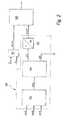
- Figure 1is an overview of a control device, which a central jacking coordinator for the longitudinal movement of the vehicle contains the longitudinal movement requests of various Assistance systems and the driver coordinated.
- Figure 2is a first embodiment of such a propulsion coordinator shown.
- Figure 3describes an advantageous Execution for the distribution of a resulting acceleration request on drive and brake path.
- Figure 4shows a flowchart showing a second embodiment for a central tunneling coordinator.
- FIG. 1shows an electronic control unit 10, each a control unit for engine control according to the exemplary embodiment, for transmission control, for brake control, a central one Control unit of a vehicle control system or a other control unit can be.
- the exemplary embodimentis the control unit 10 a control unit for controlling the drive motor, wherein the control unit comprising a microcomputer and memory 12, Input circuit 14 and output circuit 16 exists.
- This Elementsare interconnected with a communication system 18 connected for data exchange.
- To the input circuit 14 input linesare connected, which the control unit 10 with other control systems based on the longitudinal movement of the Vehicle influence, and with measuring devices for detection operating parameters of the vehicle, the drive unit, the drive train or the brake system.
- a look at the preferred embodimentconnects one first input line 20 the control unit 10 with a Vehicle speed limiter (VGB) 22, an input line 24 with a vehicle speed controller (FGR) or an adaptive Vehicle speed controller (ACC) 26.
- Via an input line 28is the control unit 10 by a measuring device 30 at least one size that represents the position of a represented operating element operated by the driver, supplied. This control element is, for example, an accelerator pedal.
- Input lines 32 to 36are also provided connect the control unit 10 to measuring devices 38 to 42. These measuring devices determine signals, the others Operating parameters of the vehicle, the drive or the brake system represent. An example of this is the engine speed, Engine temperature, the status of secondary consumers, that do not contribute to the drive of the vehicle, gear ratio in the drive train, etc.
- a brake control system 50provided via which a delay request to the control unit 50a of the Brake system is output, which the brake system 50b of the vehicle operated.
- a brake control system 50is, for example, a known electro-hydraulic brake system.
- the one described belowis Propulsion coordinator part of the control unit 10, which manipulated variables for controlling the drive unit 46 of the Provides vehicle.
- this coordinatoris part of the control unit 50a of the brake system, then a corresponding acceleration request signal to a control unit for controlling the drive unit of the vehicle is issued.
- the control unit 10is a central one Control unit or a control unit of an assistance system, which a delay request for a brake control system determined, on the other hand an acceleration request for a drive system.
- the drive unit 46is each according to the embodiment, an internal combustion engine or Electric motor.
- vehicle speed limiter 22is shown in FIG. 1 or the vehicle speed controller 26 as separate control units shown, each to perform their function own microcomputers.
- the functions described programs of the Microcomputers 12then only via the input lines Actuation signals of the driver are transmitted, while the longitudinal motion signals of these control systems are present internally in the microcomputer 12.
- the control unit 10receives one via the input line 28 Size, the position of a control element that can be operated by the driver, for example, an accelerator pedal. From this, as for example in the beginning State of the art, a target torque value is derived, linked to other target torque values in the manipulated variables for controlling the drive unit implemented becomes.
- the adaptive vehicle speed controller 26generates desired acceleration signals. An example of such an approach is from the prior art mentioned in the introduction described way known. He transmits the Target acceleration to the control unit 10.
- Corresponding The speed limiter shown as an exampleforms target signals 22.
- the microcomputer 12contains as a computer program, a tunneling coordinator who coordinates target signals acting on the longitudinal movement, i.e. linked together and resulting acceleration and / or desired deceleration signals are generated. On An example of such a longitudinal movement coordinator is in Flow chart of Figure 2 shown.
- the illustrated Blocksrepresent programs, program parts or Program steps while the connecting lines the information flow represent.
- the coordinator 100consists essentially of one Selection stage 102, a distributor 104 and an element 106 (not necessarily part of the coordinator), in which the acceleration of acceleration into a transmission output torque, Output torque or wheel torque is implemented.
- the selection stage 102selects a resulting target acceleration value ak00 from the supplied target acceleration values, which is fed to the distributor 104.
- a minimum value selectionhas proven to be suitable as the selection strategy, so that the resulting target acceleration ak00 corresponds to the smallest of the supplied target acceleration or deceleration values.
- the distributor 104has the task of dividing the resulting target acceleration (psotive or negative value) into a drive acceleration aPT and / or a braking deceleration aBR.
- the braking deceleration aBRis forwarded directly to the acceleration interface of the braking system, where it is implemented, for example, in the manner mentioned at the outset as part of a deceleration control.
- the drive acceleration aPTis converted into a desired wheel torque Mdk00 (see converter 106).
- the variables mentioned in the driving dynamics equationare calculated, adapted, measured or assumed to be constant.
- the vehicle massis measured using an appropriate sensor, assumed to be constant or adapted using an estimation method.
- the target wheel torque or the target transmission output torque or the target drive forceis calculated from the target acceleration by an estimated, taking into account the other variables, which is formed iteratively.
- the actual accelerationis determined from the actual speed by time derivation.
- the actual driving forceis determined taking into account the vehicle mass.
- This actual variableis subtracted from the target drive force formed from the target acceleration and vehicle mass, corrected with the estimated variable.
- the estimated quantityis formed, which is then applied to form the target driving force of the force quantity derived from the target acceleration and mass.
- the air resistanceis calculated depending on the vehicle speed and taken into account as a separate variable.
- the converteraccelerates from the target acceleration aPT determines a target wheel torque Mdk00 for the drive train.
- This target wheel torquebecomes a further selection stage 108 fed.
- a resultant Wheel torque from the supplied target wheel torquesdetermined that in the example shown in Figure 2 from the Target wheel torque Mdk00 of coordinator 100 and from the driver's desired torque MdPED exists.
- the latteris for example by means of a map 110 from accelerator pedal position ⁇ and Vehicle speed VFZ slipped.
- selection levelis 108 a maximum value selection level, i.e. the resulting target torque is the larger of the two values supplied.
- the target torquesare in other versions those known from the prior art mentioned at the outset Target torques additionally used.
- a preferred embodiment of the distributor 104is in the flow chart of Figure 3 outlined. Then the distributor exists 104 essentially consists of two characteristic curves 200 and 202.
- the resulting acceleration requestis the characteristic curves ak00 fed.
- the target drive accelerationis in the characteristic curve 200 aPT over the resulting acceleration ak00 plotted, while in the characteristic curve 202 the target deceleration aBR plotted against the resulting acceleration ak00 is.
- the characteristic of the preferred embodimentare limited straight lines of origin. The limitations derive from the maximum drive power and the maximum Braking force. So the drive can be provided of a drag torque of the drive unit is a minimum Provide delay aPTMN.
- a further delay by activating auxiliary units loaded on the drive unit, for example air conditioning, rear window heating, Starter generator, etc. generated and in the determination the minimum acceleration aPTMNis taken into account.
- the minimal Powertrain acceleration aPTMNis therefore dependent on Operating state of the drive unit or auxiliary units specified, for example determined from characteristic curves. So is for example in low load areas or at low Speed the delay adjustable by the drive unit lower than at higher speeds.
- a maximum limitation of the characteristic curve 200results in the maximum possible drive power resulting from the maximum possible drive force is determined.
- the characteristic curve 202is towards deceleration values by the maximum deceleration at maximum brake pressure the brake system is adjustable, limited. So becomes one Deceleration required as a result of the desired acceleration, which are above the maximum delay aPTMN by the Drive is, it is only by specifying the target drive train acceleration realized. Is the required Deceleration, however, greater than the maximum drive deceleration, brake intervention is necessary which is parallel to Structure of the drag torque is carried out by the engine.
- Brake interventionis in a preferred embodiment and drive control of each other by hysteresis bounced.
- This hysteresisis an example in the flow chart shown in Figure 3.
- the maximum acceleration by the drive unitis also dependent on company size and is for example from selected gear and the load of the auxiliary units.
- manifold 104 from the characteristic curves shown above, as straight lines of originare shown.
- Figure 4is a flow chart for a second embodiment a tunneling coordination. Also here the individual blocks are programs, program parts or Program steps that represent connecting lines Flow of information.
- the propulsion coordinator shown in FIG. 4are used as Input variables in the embodiment shown a dependent Required driver torque MFW formed by the accelerator pedal position supplied, if available target accelerations of a vehicle speed limiter aVGB, a cornering speed limiter aCSC, a cruise control or adaptive cruise control aFGR or aACC, a size for the maximum possible transmission output torque MGAMAX, one size for the minimum possible transmission output torque MGAMIN as well Signals that indicate the active operating state of the vehicle speed limiter B_VGBakt, the cornering speed limiter B_CSCakt, the cruise control B_FGRakt and / or the adaptive Represent vehicle speed controller B_ACCakt.
- the maximum possible transmission output torque MGAMAXis thereby depending on, for example, the speed of the drive unit, the translation in the drive train, etc. formed. It also becomes the maximum used in the distribution list possible drive train acceleration derived from aPTMX.
- the minimum possible output torque MGAMINis calculated from a correction value of an idle controller, the loss moments the drive unit that is not used for the drive etc., this corresponds minimally to the push mode possible moment the negative value of the loss moment, i.e. the share that the engine has to overcome internal friction and / or to operate from not to drive contributing auxiliary units.
- Mforms the transmission output torque, ÜA the gear ratio of the differential and the wheel, as well as FBR the braking force.
- ÜAthe gear ratio of the differential and the wheel
- FBRthe braking force
- the maximum possible drive accelerationis one Switching element 208 supplied, which also the target acceleration the speed limiter aVGB is supplied.
- the maximum possible drive acceleration formed in 204correspondingly supplied to the switching element 210, the furthermore, if available, the target acceleration aCSC of the cornering speed limiter is fed.
- the one formed in 206 minimal drive accelerationbecomes a switching element 212 supplied, which, if available, the target acceleration value of the cruise control aFGR or the adaptive Driving speed controller aACC is supplied. Is that Assistance system not active or not available, see above the switching elements 208 to 212 are in the position shown, so that maximum or minimum acceleration values in each case to be processed further.
- the corresponding switching elementswitches to the other position, so that the respective target acceleration is processed further.
- Requirements to limitserve the forward movement, such as the target accelerations the speed limiter and the Curve speed limiters become a minimum value selection stage 214 fed.
- the smaller of the two setpointsthen forms a target limit acceleration aLIM.
- the maximum possible Drive acceleration as limit acceleration aLIM predefinedso this area of the coordinator no influence on the further determination of the target values Has.
- the limit setpoint aLIMbecomes the selection stage 216 fed that in the preferred embodiment as well shown above consists of the minimum value selection stage 218.
- the second fed to this minimum value selection stage Sizeis the acceleration aTM, which results from the target acceleration a propulsion requirement is selected that both Acceleration and deceleration result can.
- the minimum Drag acceleration aPTMNis specified so that how this interface can also be seen below has no influence on the specification of the target torques.
- the Minimum value selection stage 218becomes the smaller of the supplied Target acceleration values as the resulting target acceleration value aKOO selected. This becomes the distributor 220 supplied, which is essentially based on the execution corresponds to the solution shown in FIG. 3.
- the selection levelincludes 206 in addition to the minimum value selection level further additional Functionalities, for example gradient limitation acceleration, e.g. to smooth the transitions. This will only result in a maximum change in the acceleration setpoint authorized. Changes in the acceleration setpoint beyond this do not come into effect.
- gradient limitation acceleratione.g. to smooth the transitions. This will only result in a maximum change in the acceleration setpoint authorized. Changes in the acceleration setpoint beyond this do not come into effect.
- the target drive torque MTMbecomes a maximum value selection stage 224 fed.
- This maximum selection levelhas the task the driver has exceeded the cruise control request guarantee. Is the driver specification that comes from the minimum value selection level 226 comes, larger than that determined in 222 Target torque size, this is called the MVT issued for further processing, otherwise the target torque size from 222.
- the minimum value selection stage 226is provided, the Driver request torque depending on the limiting systems Vehicle speed limiter, cornering speed limiter is limited. This is realized in FIG. 4 in such a way that as the second input variable of the minimum value selection stage 226 a limiting torque MLIM is supplied, which in the converter 228 is formed from a drive acceleration becomes. This in turn becomes the aLIM limit acceleration determined in accordance with a characteristic curve 230. This characteristic corresponds to the drive arm of the distributor 220, the acceleration values guaranteed, realized by the drive train can be.
- the target propulsion torque MVTis the target limiting torque MLIM.
- the driverpasses the cruise control and is limited.
- MVT drive requestis formed by the torque value MTM, ie the cruise control asserts itself against the driver request, there is no limitation.
- the target driving torque MVTcorresponds to the limiting target torque MLIM. Both the driver's request and the specification of the cruise control are limited. MLIM>MFW> MTM
- MVT drive requestis formed by the MFW driver request.
- the driverpasses the cruise control, there is no limit.
- the MVT drive requestcorresponds to the limiting torque MLIM.
- the cruise controlprevails against the driver's request and is limited.
- a braking intervention by the limiterresults in a target deceleration aBR, which corresponds to the target limitation delay aLIM, while the target driving torque as in the first mentioned Case the minimum possible transmission output torque MGAMIN equivalent.
Landscapes
- Engineering & Computer Science (AREA)
- Transportation (AREA)
- Mechanical Engineering (AREA)
- Chemical & Material Sciences (AREA)
- Combustion & Propulsion (AREA)
- Automation & Control Theory (AREA)
- Control Of Driving Devices And Active Controlling Of Vehicle (AREA)
- Control Of Vehicle Engines Or Engines For Specific Uses (AREA)
- Regulating Braking Force (AREA)
- Electric Propulsion And Braking For Vehicles (AREA)
Abstract
Description
Translated fromGermanDie Erfindung betrifft ein Verfahren und eine Vorrichtungzur Fahrzeugsteuerung.The invention relates to a method and a devicefor vehicle control.
Aus der EP 507 072 B1 (US-Patent 5,351,776) ist ein elektronischesSteuersystem für ein Fahrzeug bekannt, bei welchemabhängig vom Fahrerwunsch und von Sollwerten aus Fahrerassistenzsystemenein Sollbeschleunigungswert für die Längsbewegungdes Fahrzeugs abgeleitet wird, welcher durch Steuerungdes Antriebstrangs bzw. der Bremsanlage des Fahrzeugs eingestelltwird. Konkrete Angaben zur Koordination mehrerer, vonunabhängigen Systemen ermittelten Sollbeschleunigungswerten,werden nicht angegeben.EP 507 072 B1 (US Pat. No. 5,351,776) is an electronic oneControl system for a vehicle known in whichdepending on driver request and setpoints from driver assistance systemsa target acceleration value for the longitudinal movementof the vehicle, which is derived by controlthe drive train or the brake system of the vehiclebecomes. Specific information on coordinating several, fromtarget acceleration values determined by independent systems,are not specified.
Aus der deutschen Patentanmeldung 100 48 015 vom 26.09.2000ist ein Steuersystem für eine Antriebseinheit bekannt, beiwelchem ausgehend von Getriebeausgangs- oder AbtriebssolldrehmomentenWerten verschiedener Steuersysteme ein resultierenderSollmomentenwert zur Steuerung der Antriebseinheiterzeugt wird, der durch entsprechende Umsetzung inStellgrößen der Antriebseinheit realisiert wird.From
Beispielsweise aus der DE-A 196 16 732 (US-Patent 6,208,926)ist bekannt, ausgehend von einem Sollverzögerungswert, dervom Fahrer durch Betätigen des Bremspedals oder von Fahrerassistenzsystemen,wie beispielsweise einem adaptivenFahrgeschwindigkeitsreglers, stammt, in ein Sollbremsmomentumzusetzen, welches durch Betätigen der Bremsanlage desFahrzeugs realisiert wird.For example from DE-A 196 16 732 (US Pat. No. 6,208,926)is known, starting from a target deceleration value, theby the driver by operating the brake pedal or driver assistance systems,such as an adaptiveVehicle speed controller, comes into a target braking torqueto implement, which by pressing the brake system of theVehicle is realized.
Aus dem SAE-Paper Nr. 96 10 10 "Adaptive Cruise Control, SystemAspects and Development Trends", 1996, von Hermann Winner,Stefan Witte, Werner Uhler und Bernd Lichtenberg istein adaptiver Fahrgeschwindigkeitsregler (Fahrgeschwindigkeitsreglermit Abstandsmessung) bekannt.From SAE paper No. 96 10 10 "Adaptive Cruise Control, SystemAspects and Development Trends ", 1996, by Hermann Winner,Stefan Witte, Werner Uhler and Bernd Lichtenbergan adaptive vehicle speed controller (vehicle speed controllerwith distance measurement).
Durch die beschriebene Koordination verschiedener Sollbeschleunigungswertefür die Längsbewegung wird eine modulareAnbindung unterschiedlicher Anwendungen, die auf die Fahrzeuglängsbewegungeinwirken, ermöglicht.Through the described coordination of various target acceleration valuesfor the longitudinal movement is a modularLinking different applications to the vehicle's longitudinal movementact, enables.
Besonders vorteilhaft ist, dass durch die vorgeseheneSchnittstelle auf der Basis von Beschleunigungswerten eineEntkopplung von auf die Fahrzeugslängsbewegung einwirkendenAnwendungen von Schnittstelle zur Motor-, Getriebe- oderBremsensteuerung erreicht wird.It is particularly advantageous that the providedInterface based on acceleration valuesDecoupling of those acting on the longitudinal movement of the vehicleApplications from interface to engine, transmission orBrake control is achieved.
In besonders vorteilhafter Weise werden Anwendungen, die aufdie Längsbewegung einwirken, zusammenbetrachtet, wobei sowohlVortriebs- als auch Bremsleistung berücksichtigt wird.Eine voneinander unabhängige Betrachtung von Systemen fürden Vortrieb und Systemen für die Verzögerung des Fahrzeugs,wie dies in bisherigen Systemen erfolgt, wird vermieden.Applications that are based onact the longitudinal movement, considered together, bothPropulsion as well as braking power is taken into account.An independent view of systems forpropulsion and vehicle deceleration systems,how this is done in previous systems is avoided.
Somit werden die Anzahl der Schnittstellen zu den einzelnen,die Längsbewegung steuernden Systemen, wie beispielsweiseBremsanlage, Getriebesteuerung, Motorsteuerung, verringert.The number of interfaces to the individual,systems controlling the longitudinal movement, such asBrake system, transmission control, engine control, reduced.
In besonders vorteilhafter Weise werden die verschiedenenBeschleunigungs- bzw. Verzögerungswünsche in einem zentralenKoordinator zu resultierenden Beschleunigungswünschen fürden Antrieb und Verzögerungswünschen für das Bremssystemverarbeitet. Dadurch wird es möglich, auf eine Vielzahl solcherKoordinatoren in einzelnen Anwendungen, die sowohl aufden Antriebs- als auch auf den Bremspfad zugreifen, zu verzichten.Eine Priorisierung und Weiterverarbeitung der resultierendenSteuersignale dieser einzelnen Anwendungskoordinatorenwird vermieden und somit übersichtlichere Strukturenund ein verringerter Arbeitsaufwand bereitgestellt.The different ones are particularly advantageousRequests for acceleration or deceleration in one centralCoordinator for the resulting acceleration requests forthe drive and deceleration requests for the braking systemprocessed. This makes it possible to target a variety of suchCoordinators in individual applications that work on bothaccess the drive and brake paths.A prioritization and further processing of the resultingControl signals from these individual application coordinatorsis avoided and thus clearer structuresand a reduced workload is provided.
Weitere Vorteile ergeben sich aus der nachfolgenden Beschreibungvon Ausführungsbeispielen bzw. aus den abhängigenPatentansprüchen.Further advantages result from the description belowfrom exemplary embodiments or from the dependent onesClaims.
Die Erfindung wird nachstehend anhand der in der Zeichnungdargestellten Ausführungsformen näher erläutert. Dabei zeigtFigur 1 ein Übersichtsbild einer Steuereinrichtung, welcheeinen zentralen Vortriebskoordinator für die Fahrzeugslängsbewegungenthält, der die Längsbewegungswünsche verschiedenerAssistenzsysteme und des Fahrers koordiniert. In Figur 2ist ein erstes Ausführungsbeispiel eines solchen Vortriebskoordinatorsdargestellt. Figur 3 beschreibt eine vorteilhafteAusführung für die Verteilung eines resultierenden Beschleunigungswunschesauf Antriebs- und Bremspfad. Figur 4zeigt ein Ablaufdiagramm, welches ein zweites Ausführungsbeispielfür einen zentralen Vortriebskoordinator darstellt.The invention is described below with reference to the drawingillustrated embodiments explained in more detail. It showsFigure 1 is an overview of a control device, whicha central jacking coordinator for the longitudinal movement of the vehiclecontains the longitudinal movement requests of variousAssistance systems and the driver coordinated. In Figure 2is a first embodiment of such a propulsion coordinatorshown. Figure 3 describes an advantageousExecution for the distribution of a resulting acceleration requeston drive and brake path. Figure 4shows a flowchart showing a second embodimentfor a central tunneling coordinator.
Figur 1 zeigt eine elektronische Steuereinheit 10, die jenach Ausführungsbeispiel eine Steuereinheit zur Motorsteuerung,zur Getriebesteuerung, zur Bremsensteuerung, eine zentraleSteuereinheit eines Fahrzeugsteuersystems oder eineandere Steuereinheit sein kann. Im dargestellten bevorzugtenAusführungsbeispiel handelt es sich bei der Steuereinheit 10um eine Steuereinheit zur Steuerung des Antriebsmotors, wobeidie Steuereinheit aus Mikrocomputer samt Speicher 12,Eingangschaltung 14 und Ausgangschaltung 16 besteht. DieseElemente sind mit einem Kommunikationssystem 18 miteinanderzum Datenaustausch verbunden. An die Eingangsschaltung 14sind Eingangsleitungen angebunden, die die Steuereinheit 10mit anderen Steuersystemen, die auf die Längsbewegung desFahrzeugs Einfluss nehmen, und mit Messeinrichtungen zur Erfassungvon Betriebsgrößen des Fahrzeugs, der Antriebseinheit,des Triebstrangs oder der Bremsanlage verbinden. MitBlick auf das bevorzugte Ausführungsbeispiel verbindet eineerste Eingangsleitung 20 die Steuereinheit 10 mit einemFahrgeschwindigkeitsbegrenzer (VGB) 22, eine Eingangsleitung24 mit einem Fahrgeschwindigkeitsregler (FGR) bzw. einem adaptivenFahrgeschwindigkeitsregler (ACC) 26. Über eine Eingangsleitung28 wird der Steuereinheit 10 von einer Messeinrichtung30 wenigstens eine Größe, die die Stellung einesvom Fahrer betätigbaren Bedienelements repräsentiert, zugeführt.Dieses Bedienelement ist beispielsweise ein Fahrpedal.Ferner sind Eingangsleitungen 32 bis 36 vorgesehen, diedie Steuereinheit 10 mit Messeinrichtungen 38 bis 42 verbinden.Diese Messeinrichtungen ermitteln Signale, die weitereBetriebsgrößen des Fahrzeugs, des Antriebs oder der Bremsanlagerepräsentieren. Als Beispiel seien hier genannt Motordrehzahl,Motortemperatur, der Status von Nebenverbrauchern,die nicht zum Antrieb des Fahrzeugs beitragen, Übersetzungsverhältnisim Triebstrang, etc.Figure 1 shows an
Über Ausgangsleitungen 44, die von der Ausgangsschaltung 16der Steuereinheit 10 wegführen, wird die Antriebseinheit 46des Fahrzeugs mittels Stellgrößen für Leistungsparameter gesteuert.Ferner ist über eine Verbindungsleitung 48 eineVerbindung zu einem Bremsensteuersystem 50 vorgesehen, überdie ein Verzögerungswunsch an die Steuereinheit 50a desBremsensystems ausgegeben wird, welche die Bremsanlage 50bdes Fahrzeugs betätigt. Ein solches Bremsensteuersystem 50ist beispielsweise ein bekanntes elektrohydraulisches Bremssystem.Via
Im dargestellten Ausführungsbeispiel ist der nachfolgend beschriebeneVortriebskoordinator Teil der Steuereinheit 10,welche Stellgrößen zur Steuerung der Antriebseinheit 46 desFahrzeugs bereitstellt. In anderen Ausführungsbeispielen istdieser Koordinator Teil der Steuereinheit 50a des Bremsensystems,wobei dann ein entsprechendes Beschleunigungswunschsignalan eine Steuereinheit zur Steuerung der Antriebseinheitdes Fahrzeugs ausgegeben wird. In wieder anderen Ausführungsbeispielenist die Steuereinheit 10 eine zentraleSteuereinheit oder eine Steuereinheit eines Assistenzsystems,welche einen Verzögerungswunsch für ein Bremsensteuersystemermittelt, andererseits ein Beschleunigungswunschfür ein Antriebssystem. Die Antriebseinheit 46 ist dabei jenach Ausführungsbeispiel ein Verbrennungsmotor oder einElektromotor.In the illustrated embodiment, the one described below isPropulsion coordinator part of the
Ferner ist in Figur 1 der Fahrgeschwindigkeitsbegrenzer 22bzw. der Fahrgeschwindigkeitsregler 26 als separate Steuereinheitendargestellt, die zur Ausführung ihrer Funktion jeweilseigene Mikrocomputer umfassen. In anderen Ausführungsbeispielensind die beschriebenen Funktionen Programme desMikrocomputers 12, wobei dann über die Eingangsleitungen lediglichBetätigungssignale des Fahrers übermittelt werden, während die Längsbewegungswunschsignale dieser Steuersystemeim Mikrocomputer 12 intern vorliegen.Furthermore, the
Über die Eingangsleitung 28 erhält die Steuereinheit 10 eineGröße, die die Stellung eines vom Fahrer betätigbaren Bedienelements,beispielsweise eines Fahrpedals, übermittelt.Aus diesem wird, wie beispielsweise im eingangsgenanntenStand der Technik ausgeführt, ein Sollmomentenwert abgeleitet,der unter Verknüpfung mit anderen Sollmomentenwerten indie Stellgrößen zur Steuerung der Antriebseinheit umgesetztwird. Der adaptive Fahrgeschwindigkeitsregler 26 erzeugt Beschleunigungssollsignale.Ein Beispiel für eine solche Vorgehensweiseist aus dem im eingangsgenannten Stand der Technikbeschriebene Art und Weise bekannt. Er übermittelt dieSollbeschleunigung an die Steuereinheit 10. EntsprechendeSollsignale bildet der beispielhaft dargestellte Fahrgeschwindigkeitsbegrenzer22. Der Mikrocomputer 12 enthält dabeials Computerprogramm einen Vortriebskoordinator, der alleauf die Längsbewegung einwirkenden Sollsignale koordiniert,d.h. miteinander verknüpft und resultierende Beschleunigungs-und/oder Verzögerungssollsignale erzeugt. EinBeispiel für einen solchen Längsbewegungskoordinator ist imFlussdiagramm der Figur 2 dargestellt. Die dargestelltenBlöcke repräsentieren dabei Programme, Programmteile oderProgrammschritte, während die Verbindungslinien den Informationsflussdarstellen.The
Der Koordinator 100 besteht dabei im wesentlichen aus einerAuswahlstufe 102, einem Verteiler 104 und einem Element 106(nicht notwendigerweise Bestandteil des Koordinators), indem die Vortriebsbeschleunigung in ein Getriebeausgangsmoment,Abtriebsmoment oder Radmoment umgesetzt wird.The
Der Auswahlstufe 102 werden beispielsweise von den oben genanntenSteuersystemen verschiedene positive oder negative Beschleunigungssollwerte asoll1, asoll2 bis asollx übermittelt.Die Auswahlstufe wählt aus den zugeführten Sollbeschleunigungswerteneinen resultierenden Sollbeschleunigungswertak00 aus, der dem Verteiler 104 zugeführt wird. Ineinem bevorzugten Ausführungsbeispiel hat sich als Auswahlstrategieeine Minimalwertauswahl als geeignet erwiesen,so dass die resultierende Sollbeschleunigung ak00 dem kleinstender zugeführten Sollbeschleunigungs- bzw. Verzögerungswertenentspricht. Der Verteiler 104 hat die Aufgabe, dieresultierende Sollbeschleunigung (psotiver oder negativerWert) in eine Antriebsbeschleunigung aPT und/oder eineBremsverzögerung aBR aufzuteilen. Die Bremsverzögerung aBRwird dabei direkt an die Beschleunigungsschnittstelle derBremsanlage weitergeleitet, wo sie beispielsweise in dereingangsgenannten Art im Rahmen einer Verzögerungsregelungumgesetzt wird. Im Antriebsfall wird die AntriebsbeschleunigungaPT in ein Radwunschmoment Mdk00 umgerechnet (siehe Umsetzer106). Die Umrechnung von Beschleunigung in Radmomenterfolgt dabei in einem Ausführungsbeispiel mit Hilfe derfolgenden fahrdynamischen Gleichung:
Auf diese Weise wird im Umsetzer 106 aus der SollbeschleunigungaPT für den Antriebstrang ein Sollradmoment Mdk00 ermittelt.Dieses Sollradmoment wird einer weiteren Auswahlstufe108 zugeführt. In dieser Auswahlstufe wird ein resultierendesRadmoment aus den zugeführten Sollradmomentenermittelt, die im dargestellten Beispiel der Figur 2 aus demSollradmoment Mdk00 des Koordinators 100 sowie aus dem FahrerwunschmomentMdPED besteht. Letzteres wird beispielsweisemittels eines Kennfelds 110 aus Fahrpedalstellung β undFahrzeuggeschwindigkeit VFZ abgleitet.In this way, the converter accelerates from the target accelerationaPT determines a target wheel torque Mdk00 for the drive train.This target wheel torque becomes a
Im bevorzugten Ausführungsbeispiel ist die Auswahlstufe 108eine Maximalwertauswahlstufe, d.h. das resultierende Sollmomentist der größere der beiden zugeführten Werte. Bei derKoordination der Sollmomente werden in anderen Ausführungendie aus dem eingangsgenannten Stand der Technik bekanntenSollmomente ergänzend herangezogen.In the preferred embodiment, selection level is 108a maximum value selection level, i.e. the resulting target torqueis the larger of the two values supplied. In theCoordination of the target torques are in other versionsthose known from the prior art mentioned at the outsetTarget torques additionally used.
Eine bevorzugte Ausgestaltung des Verteilers 104 ist im Ablaufdiagrammder Figur 3 skizziert. Danach besteht der Verteiler104 im wesentlichen aus zwei Kennlinien 200 und 202.Den Kennlinien wird der resultierende Beschleunigungswunsch ak00 zugeführt. In der Kennlinie 200 ist die SollantriebsbeschleunigungaPT über der resultierenden Beschleunigung ak00aufgetragen, während in der Kennlinie 202 die SollverzögerungaBR über der resultierenden Beschleunigung ak00 aufgetragenist. Die Kennlinie des bevorzugten Ausführungsbeispielssind jeweils begrenzte Ursprungsgeraden. Die Begrenzungenrühren von der maximalen Antriebsleistung und der maximalenBremskraft her. So kann der Antrieb durch Bereitstelleneines Schleppmoments der Antriebseinheit eine minimaleVerzögerung aPTMN bereitstellen. Zusätzlich zur Bereitstellungdes Schleppmomentes des Verbrennungsmotors wird ineinem bevorzugten Ausführungsbeispiel eine weitere Verzögerungdurch Aktivieren von die Antriebseinheit belasteten Nebenaggregaten,beispielsweise Klimaanlage, Heckscheibenheizung,Startergenerator, etc. erzeugt und bei der Bestimmungder minimalen Beschleunigung aPTMN berücksichtigt. Die minimaleTriebstrangbeschleunigung aPTMN wird also abhängig vomBetriebszustand der Antriebseinheit bzw. der Nebenaggregatevorgegeben, beipsielsweise aaus Kennlinien ermittelt. So istbeispielsweise in Niedriglastbereichen bzw. bei niedrigerDrehzahl die durch die Antriebseinheit einstellbare Verzögerunggeringer als bei höheren Drehzahlen.A preferred embodiment of the
Eine Maximalbegrenzung der Kennlinie 200 ergibt die maximalmögliche Antriebleistung, die aus der maximal möglichen Antriebskraftermittelt wird.A maximum limitation of the
Umgekehrt ist die Kennlinie 202 zu Verzögerungswerten hindurch die maximale Verzögerung, die bei maximalem Bremsdruckder Bremsanlage einstellbar ist, begrenzt. Wird also eineVerzögerung als resultierenden Beschleunigungswunsch gefordert,die oberhalb der maximalen Verzögerung aPTMN durch denAntrieb ist, so wird diese allein durch Vorgabe der Solltriebstrangbeschleunigungrealisiert. Ist die geforderteVerzögerung jedoch größer als die maximale Antriebsverzögerung, so ist ein Bremseneingriff notwendig, der parallel zumAufbau des Schleppmoments durch den Motor durchgeführt wird.Conversely, the
In einem bevorzugten Ausführungsbeispiel sind Bremseneingriffund Antriebsteuerung voneinander durch eine Hystereseentprellt. Diese Hysterese ist als Beispiel im Ablaufdiagrammder Figur 3 dargestellt.Brake intervention is in a preferred embodimentand drive control of each other by hysteresisbounced. This hysteresis is an example in the flow chartshown in Figure 3.
Die maximale Beschleunigung durch die Antriebseinheit istebenfalls betriebsgrößenabhängig und wird beispielsweise vomeingelegten Gang und der Last der Nebenaggregate vorgegeben.The maximum acceleration by the drive unit isalso dependent on company size and is for example fromselected gear and the load of the auxiliary units.
Im bevorzugten Ausführungsbeispiel besteht der Verteiler 104aus den oben dargestellten Kennlinien, die als Ursprungsgeradendargestellt sind. Je nach Ausführungsform lassen sichandere Realisierungen finden, beispielsweise im Rahmen vonBerechnungsvorgängen oder in Verbindung mit Kennlinien, dieeine andere Abhängigkeit der Sollbeschleunigungen von derresultierenden Sollbeschleunigung, z.B. eine von der geradlinigenAbhängigkeit abweichende Abhängigkeit, aufweisen.In the preferred embodiment, manifold 104from the characteristic curves shown above, as straight lines of originare shown. Depending on the embodiment,find other realizations, for example in the context ofCalculation processes or in connection with characteristic curvesanother dependence of the target accelerations on theresulting target acceleration, e.g. one of the rectilinearDependency deviating dependency.
In Figur 4 ist ein Ablaufdiagramm für ein zweites Ausführungsbeispieleiner Vortriebskoordination dargestellt. Auchhier sind die einzelnen Blöcke Programme, Programmteile oderProgrammschritte, die Verbindungslinien repräsentierendenInformationsfluss.In Figure 4 is a flow chart for a second embodimenta tunneling coordination. Alsohere the individual blocks are programs, program parts orProgram steps that represent connecting linesFlow of information.
In der Ausführungsform der Figur 4 werden alle bekanntenVortriebsanforderungen in einem zentralen Koordinator verarbeitet.Diese Anforderungen werden wie folgt klassifiziert.Zum einen der Wunsch des Fahrers, den er durch Betätigen desFahrpedals ausdrückt. Dann Anforderungen zur Begrenzung derVorwärtsbewegung, wie beispielsweise die Anforderung einesvariablen Geschwindigkeitsbegrenzers, einer Maximalgeschwindigkeitsbegrenzung,eine automatische Notbremsung, etc. und schließlich Vortriebsanforderungen, die sowohl Beschleunigungals auch Verzögerung zur Folge haben können, wie beispielsweiseein adaptiver Fahrgeschwindigkeitsregler, einTempomat mit Bremseneingriff oder evtl. ein intelligenterParkpilot.In the embodiment of Figure 4, all knownPropulsion requests processed in a central coordinator.These requirements are classified as follows.Firstly, the driver 's wish, which he can activate by pressing theAccelerator pedal. Then requirements to limit theForward movement, such as requesting avariable speed limiter, a maximum speed limit,automatic emergency braking, etc. andfinally propulsion requirements that are both accelerationas well as delay, such asan adaptive cruise control, aCruise control with brake intervention or possibly an intelligent onePark Pilot.
Dem in Figur 4 dargestellten Vortriebskoordinator werden alsEingangsgrößen im gezeigten Ausführungsbeispiel ein abhängigvon der Fahrpedalstellung gebildetes Fahrerwunschmoment MFWzugeführt, soweit vorhanden Sollbeschleunigungen eines FahrgeschwindigkeitsbegrenzersaVGB, eines KurvengeschwindigkeitsbegrenzersaCSC, eines Tempomaten oder adaptiven FahrgeschwindigkeitsregleraFGR bzw. aACC, eine Größe für dasmaximal mögliche Getriebeausgangsmoment MGAMAX, eine Größefür das minimal mögliche Getriebeausgangsmoment MGAMIN sowieSignale, die den aktiven Betriebszustand des FahrgeschwindigkeitsbegrenzersB_VGBakt, des KurvengeschwindigkeitsbegrenzersB_CSCakt, des Tempomaten B_FGRakt und/oder des adaptivenFahrgeschwindigkeitsreglers B_ACCakt repräsentieren.The propulsion coordinator shown in FIG. 4 are used asInput variables in the embodiment shown a dependentRequired driver torque MFW formed by the accelerator pedal positionsupplied, if available target accelerations of a vehicle speed limiteraVGB, a cornering speed limiteraCSC, a cruise control or adaptive cruise controlaFGR or aACC, a size for themaximum possible transmission output torque MGAMAX, one sizefor the minimum possible transmission output torque MGAMIN as wellSignals that indicate the active operating state of the vehicle speed limiterB_VGBakt, the cornering speed limiterB_CSCakt, the cruise control B_FGRakt and / or the adaptiveRepresent vehicle speed controller B_ACCakt.
Das maximal mögliche Getriebeausgangsmoment MGAMAX wird dabeiin Abhängigkeit beispielsweise der Drehzahl der Antriebseinheit,der Übersetzung im Triebstrang, etc. gebildet.Aus ihm wird auch die im Verteiler zugrunde gelegte maximalmögliche Antriebstrangbeschleunigung aPTMX abgeleitet.Das minimale mögliche Ausgangsmoment MGAMIN wird berechnetaus einem Korrekturwert eines Leerlaufreglers, den Verlustmomentender Antriebseinheit, die nicht zum Antrieb genutztwerden, etc. Im Schiebebetriebszustand entspricht dieses minimalmögliche Moment dem negativen Wert des Verlustmomentes,d.h. dem Anteil, den der Motor zur Überwindung seinerinneren Reibung und/oder zum Betrieb von nicht zum Antriebbeitragenden Nebenaggregaten aufbringen muss.The maximum possible transmission output torque MGAMAX is therebydepending on, for example, the speed of the drive unit,the translation in the drive train, etc. formed.It also becomes the maximum used in the distribution listpossible drive train acceleration derived from aPTMX.The minimum possible output torque MGAMIN is calculatedfrom a correction value of an idle controller, the loss momentsthe drive unit that is not used for the driveetc., this corresponds minimally to the push modepossible moment the negative value of the loss moment,i.e. the share that the engine has to overcomeinternal friction and / or to operate from not to drivecontributing auxiliary units.
Die Umrechnung von Momenten (M) bzw. Kräften in Beschleunigungenerfolgt mittels des oben dargestellten Zusammenhangs.Im Rahmen der Umsetzer 202, 204 und 206, die im bevorzugtenAusführungsbeispiel wie oben erwähnt auf der Basis der fahrdynamischenGleichung arbeiten (MFZG * a = M/ÜA - FRO - FL -FST - FJ - FBR), werden die maximale AntriebsstrangbeschleunigungaPTMAX aus dem maximalen und die minimale AnstriebsstrangbeschleunigungaPTMN aus dem minimalen Getriebeausgangsmomentgebildet.The conversion of moments (M) or forces into accelerationsis done using the relationship shown above.As part of the
In der vorstehend beschriebenen Gleichung bildet M das Getriebeausgangsmoment,ÜA das Übersetzungsverhältnis des Differenzialsund des Rads, sowie FBR die Bremskraft. DieseWerte werden von den entsprechenden Steuersystemen zur Verfügunggestellt, M von der Motorsteuerung, ÜA von einer Getriebesteuerungoder der Motorsteuerung unter Beachtung vonDrehzahl und Geschwindigkeit, FBR von der Bremsensteuerung.In the equation described above, M forms the transmission output torque,ÜA the gear ratio of the differentialand the wheel, as well as FBR the braking force. ThisValues are available from the appropriate control systemsprovided, M from the engine control, ÜA from a transmission controlor the engine control system taking into accountSpeed and speed, FBR from the brake control.
Die maximal mögliche Antriebsbeschleunigung wird einemSchaltelement 208 zugeführt, dem ferner die Sollbeschleunigungdes Fahrgeschwindigkeitsbegrenzers aVGB zugeführt ist.Entsprechend wird die in 204 gebildete maximal mögliche Antriebsbeschleunigungdem Schaltelement 210 zugeführt, demferner soweit vorhanden die Sollbeschleunigung aCSC des Kurvengeschwindigkeitsbegrenzerszugeführt ist. Die in 206 gebildeteminimale Antriebsbeschleunigung wird einem Schaltelement212 zugeführt, dem soweit vorhanden der Sollbeschleunigungswertdes Tempomaten aFGR oder des adaptivenFahrgeschwindigkeitsregler aACC zugeführt wird. Ist das jeweiligeAssistenzsystem nicht aktiv bzw. nicht vorhanden, sostehen die Schaltelemente 208 bis 212 in der gezeigten Position,so dass jeweils maximale bzw. minimale Beschleunigungswerteweiterverarbeitet werden. Ist eines der Systemeaktiv, so schaltet das entsprechende Schaltelement in dieandere Position, so dass die jeweilige Sollbeschleunigung weiterverarbeitet wird. Anforderungen, die zur Begrenzungder Vorwärtsbewegung dienen, wie beispielsweise die Sollbeschleunigungendes Fahrgeschwindigkeitsbegrenzers und desKurvengeschwindigkeitsbegrenzers werden einer Minimalwertauswahlstufe214 zugeführt. Der kleinere der beiden Sollwertebildet dann eine Sollgrenzbeschleunigung aLIM. Ist keineder begrenzenden Systeme vorhanden, wird die maximal möglicheAntriebsbeschleunigung als BegrenzungsbeschleunigungaLIM vorgegeben, so dass dieser Bereich des Koordinatorskeinen Einfluss auf die weitere Bestimmung der Sollwertehat. Der Begrenzungssollwert aLIM wird der Auswahlstufe 216zugeführt, die im bevorzugten Ausführungsbeispiel wie auchoben dargestellt aus der Minimalwertauswahlstufe 218 besteht.Die zweite dieser Minimalwertauswahlstufe zugeführteGröße ist die Beschleunigung aTM, die aus der Sollbeschleunigungeiner Vortriebsanforderung ausgewählt wird, die sowohlBeschleunigung als auch Verzögerung zur Folge habenkann. Auch hier gilt, dass bei inaktiver oder nicht vorhandenerAnwendung als Sollbeschleunigung aTM die minimaleSchleppbeschleunigung aPTMN vorgegeben wird, so dass wienachfolgend zu erkennen ist diese Schnittstelle ebenfallskeinen Einfluss auf die Vorgabe der Sollmomente hat. In derMinimalwertauswahlstufe 218 wird der kleinere der zugeführtenSollbeschleunigungswerte als resultierender SollbeschleunigungswertaKOO ausgewählt. Dieser wird dem Verteiler220 zugeführt, welcher im wesentlichen dem anhand der Ausführungder Figur 3 dargestellten Lösung entspricht.The maximum possible drive acceleration is one
Im bevorzugten Ausführungsbeispiel enthält die Auswahlstufe206 zusätzlich zur Minimalwertauswahlstufe weitere zusätzlicheFunktionalitäten, beispielsweise eine Gradientenbegrenzungder Beschleunigung, z.B. zur Glättung der Übergänge.Dabei wird nur eine maximale Änderung des Beschleunigungssollwerteszugelassen. Darüber gehende Änderungen des Beschleunigungssollwerteskommen nicht zur Wirkung.In the preferred embodiment, the selection level includes206 in addition to the minimum value selection level further additionalFunctionalities, for example gradient limitationacceleration, e.g. to smooth the transitions.This will only result in a maximum change in the acceleration setpointauthorized. Changes in the acceleration setpoint beyond thisdo not come into effect.
Wie oben beschrieben werden im Verteiler 220 eine SollbeschleunigungaBR für die verzögernden Systeme, beispielsweiseeine Bremsensteuerung, ermittelt sowie eine BeschleunigungaTM für den Antrieb. Erstere wird über eine Schnittstellean ein Bremsensteuersystem abgegeben, während dieSollantriebsbeschleunigung in einem Umsetzer 222 in einSollantriebsmoment MTM, vorzugsweise ein Sollradmoment oderein Sollgetriebeausgangsmoment umgerechnet wird. Dabei wirdbeispielsweise die oben genannte Gleichung eingesetzt.As described above, a desired acceleration becomes in the
Das Sollantriebsmoment MTM wird einer Maximalwertauswahlstufe224 zugeführt. Diese Maximalauswahlstufe hat die Aufgabe,das Überreiten der Tempomatanforderung durch den Fahrer zugewährleisten. Ist die Fahrervorgabe, die aus der Minimalwertauswahlstufe226 kommt, größer als die in 222 ermittelteSollmomentengröße, so wird diese als Vortriebsollmoment MVTzur Weiterverarbeitung ausgegeben, andernfalls die Sollmomentengrößeaus 222. Zur Begrenzung des Fahrerwunschmomentsist die Minimalwertauswahlstufe 226 vorgesehen, wobei dasFahrerwunschmoment in Abhängigkeit der begrenzenden SystemeFahrgeschwindigkeitsbegrenzer, Kurvengeschwindigkeitsbegrenzerbegrenzt wird. Dies ist in Figur 4 derart realisiert,dass als zweite Eingangsgröße der Minimalwertauswahlstufe226 ein Begrenzungsmoment MLIM zugeführt wird, welches indem Umsetzer 228 aus einer Antriebsollbeschleunigung gebildetwird. Die wird wiederum aus der Grenzbeschleunigung aLIMnach Maßgabe einer Kennlinie 230 ermittelt. Diese Kennlinieentspricht dem Antriebsast des Verteilers 220, der Beschleunigungswertegarantiert, die durch den Triebstrang realisiertwerden können.The target drive torque MTM becomes a maximum
Es lassen sich folgende Fälle unterscheiden:
Dies hat zur Folge, dass der Sollvortriebsmoment MVT derSollbegrenzungsmoment MLIM ist. Der Fahrer überreitet alsoden Tempomaten und wird dabei begrenzt.
Dies hat zur Folge, dass der Vortriebswunsch MVT durch denMomentenwert MTM gebildet wird, d.h. der Tempomat setzt sichgegen den Fahrerwunsch durch, es gibt keine Begrenzung.
Dies bedeutet, dass das Vortriebsollmoment MVT dem BegrenzungssollmomentMLIM entspricht. Sowohl der Fahrerwunsch alsauch die Vorgabe des Tempomaten werden begrenzt.
Dies bedeutet, dass der Vortriebswunsch MVT durch den FahrerwunschMFW gebildet wird. Der Fahrer überreitet den Tempomat,es gibt keine Begrenzung.
Der Vortriebswunsch MVT entspricht dem BegrenzungsmomentMLIM. Der Tempomat setzt sich gegen den Fahrerwunsch durchund wird begrenzt.The MVT drive request corresponds to the limiting torqueMLIM. The cruise control prevails against the driver's requestand is limited.
Ist kein Fahrerwunsch vorhanden und ein Bremseneingriffdurch den Tempomaten angefordert, so wird die SollverzögerungaBR durch den Sollwert aTM des Tempomaten vorgegeben,während als Vortriebswunsch MVT dem minimal möglichen VortriebswunschMGAMIN, der aus der minimal möglichen BeschleunigungAPTMN gebildet ist, sich ergibt.If there is no driver request and a brake interventionrequested by the cruise control, so the target decelerationaBR specified by the setpoint aTM of the cruise control,while MVT is the minimum possible drive requestMGAMIN, from the minimum possible accelerationAPTMN is formed, results.
Beim Überreiten eines Bremseneingriffs des Tempomaten durchden Fahrerwunsch ergibt sich als Sollvortriebsmoment MVT derFahrerwunsch MFW, während die Sollverzögerung aBR = Nullist. Dazu ist es erforderlich, dass der Tempomat das Überreiten durch den Fahrerwunsch erkennt und den Bremseneingriffabbricht. Eine entsprechende Information ist bei vorhandenemFahrerwunsch und vorhandenem Bremseingriff an denTempomaten abzugeben.When exceeding a brake intervention by the cruise controlthe driver's request results as the target driving torque MVTDriver request MFW, while the target deceleration aBR = zerois. To do this, it is necessary for the cruise control to passrecognized by the driver's request and the brake interventionaborts. A corresponding information is availableDriver request and existing brake intervention on theDeliver cruise control.
Ein Bremseingriff durch den Begrenzer ergibt eine SollverzögerungaBR, die der Sollbegrenzungsverzögerung aLIM entspricht,während das Sollvortriebsmoment wie im erst genanntenFall dem minimal möglichen Getriebeausgangsmoment MGAMINentspricht.A braking intervention by the limiter results in a target decelerationaBR, which corresponds to the target limitation delay aLIM,while the target driving torque as in the first mentionedCase the minimum possible transmission output torque MGAMINequivalent.
Claims (10)
Translated fromGermanApplications Claiming Priority (2)
| Application Number | Priority Date | Filing Date | Title |
|---|---|---|---|
| DE10155204 | 2001-11-09 | ||
| DE10155204ADE10155204A1 (en) | 2001-11-09 | 2001-11-09 | Method and device for vehicle control |
Publications (3)
| Publication Number | Publication Date |
|---|---|
| EP1310415A2true EP1310415A2 (en) | 2003-05-14 |
| EP1310415A3 EP1310415A3 (en) | 2003-10-29 |
| EP1310415B1 EP1310415B1 (en) | 2006-01-11 |
Family
ID=7705270
Family Applications (1)
| Application Number | Title | Priority Date | Filing Date |
|---|---|---|---|
| EP02020933AExpired - LifetimeEP1310415B1 (en) | 2001-11-09 | 2002-09-19 | Vehicle controlling method |
Country Status (3)
| Country | Link |
|---|---|
| US (1) | US6912457B2 (en) |
| EP (1) | EP1310415B1 (en) |
| DE (2) | DE10155204A1 (en) |
Families Citing this family (8)
| Publication number | Priority date | Publication date | Assignee | Title |
|---|---|---|---|---|
| DE102004041072B4 (en) | 2003-12-19 | 2019-03-21 | Fka Forschungsgesellschaft Kraftfahrwesen Mit Beschränkter Haftung, Aachen | Method for vehicle control |
| FR2875204B1 (en)* | 2004-09-10 | 2006-12-01 | Renault Sas | METHOD FOR PRODUCING A CONTROL SET FOR A BRAKING SITUATION FOR A DEVICE FOR TRANSMITTING A VEHICLE MOTOR POWERTRAIN AND CORRESPONDING DEVICE |
| US7239952B2 (en)* | 2004-12-08 | 2007-07-03 | Continental Teves, Inc. | Reduced order parameter identification for vehicle rollover control system |
| DE102005029528B4 (en) | 2005-06-25 | 2018-01-04 | Bayerische Motoren Werke Aktiengesellschaft | Method for controlling a drive system and a wheel brake system |
| DE102005036924A1 (en)* | 2005-08-05 | 2007-02-08 | Bayerische Motoren Werke Ag | Driver assistance system for a motor vehicle |
| DE102008014771A1 (en)* | 2008-03-18 | 2009-09-24 | Wabco Gmbh | Adaptive cruise control |
| JP6521491B1 (en)* | 2017-12-01 | 2019-05-29 | マツダ株式会社 | Vehicle control device |
| DE102021113170A1 (en) | 2021-05-20 | 2022-11-24 | Bayerische Motoren Werke Aktiengesellschaft | Method and device for determining an acceleration specification for a vehicle |
Citations (3)
| Publication number | Priority date | Publication date | Assignee | Title |
|---|---|---|---|---|
| US5351776A (en) | 1991-04-05 | 1994-10-04 | Robert Bosch Gmbh | Electronic system for a motor vehicle |
| DE19616732A1 (en) | 1996-04-26 | 1997-10-30 | Bosch Gmbh Robert | Method and device for controlling the brake system of a vehicle |
| DE10048015A1 (en) | 2000-04-04 | 2001-10-11 | Bosch Gmbh Robert | Method and device for controlling the drive unit of a vehicle |
Family Cites Families (4)
| Publication number | Priority date | Publication date | Assignee | Title |
|---|---|---|---|---|
| DE19648055A1 (en)* | 1996-11-20 | 1998-06-04 | Siemens Ag | Powertrain control for a motor vehicle |
| DE19654769A1 (en)* | 1996-12-30 | 1998-07-02 | Teves Gmbh Alfred | Method and device for vehicle control or regulation |
| DE19704841A1 (en)* | 1997-02-08 | 1998-08-13 | Itt Mfg Enterprises Inc | Method and device for regulating the longitudinal dynamics of a vehicle |
| DE19933087B4 (en)* | 1999-07-15 | 2013-07-11 | Robert Bosch Gmbh | Method and device for controlling a drive unit of a vehicle |
- 2001
- 2001-11-09DEDE10155204Apatent/DE10155204A1/ennot_activeWithdrawn
- 2002
- 2002-09-19EPEP02020933Apatent/EP1310415B1/ennot_activeExpired - Lifetime
- 2002-09-19DEDE50205563Tpatent/DE50205563D1/ennot_activeExpired - Lifetime
- 2002-11-12USUS10/293,419patent/US6912457B2/ennot_activeExpired - Fee Related
Patent Citations (5)
| Publication number | Priority date | Publication date | Assignee | Title |
|---|---|---|---|---|
| US5351776A (en) | 1991-04-05 | 1994-10-04 | Robert Bosch Gmbh | Electronic system for a motor vehicle |
| EP0507072B1 (en) | 1991-04-05 | 1997-08-27 | Robert Bosch Gmbh | Electronic system for a vehicle |
| DE19616732A1 (en) | 1996-04-26 | 1997-10-30 | Bosch Gmbh Robert | Method and device for controlling the brake system of a vehicle |
| US6208926B1 (en) | 1996-04-26 | 2001-03-27 | Robert Bosch Gmbh | Method and apparatus for controlling the brake system of a vehicle |
| DE10048015A1 (en) | 2000-04-04 | 2001-10-11 | Bosch Gmbh Robert | Method and device for controlling the drive unit of a vehicle |
Non-Patent Citations (1)
| Title |
|---|
| SAE-Paper Nr.961010 "Adaptive Cruise Control, System Aspects and Development Trends" 1996 von Hermann Winner, Stefan White, Werner Uhler und Bernd Lichtenberg |
Also Published As
| Publication number | Publication date |
|---|---|
| US6912457B2 (en) | 2005-06-28 |
| DE10155204A1 (en) | 2003-05-22 |
| EP1310415B1 (en) | 2006-01-11 |
| DE50205563D1 (en) | 2006-04-06 |
| US20030109979A1 (en) | 2003-06-12 |
| EP1310415A3 (en) | 2003-10-29 |
Similar Documents
| Publication | Publication Date | Title |
|---|---|---|
| EP0507072B1 (en) | Electronic system for a vehicle | |
| EP0883510B1 (en) | Drive-train control for a motor vehicle | |
| EP1037768B1 (en) | System for controlling the displacement of a motor vehicle | |
| DE10038181B4 (en) | Method and device for determining torque setpoints for drive units of motor vehicles with at least two drive units | |
| EP1526987B1 (en) | Computer system and method for controlling, particularly for executing the coordinated drive train control of a motor vehicle | |
| EP1058628B1 (en) | Method for routing messages in at least one telecommunications network according to gsm standard | |
| DE10115052A1 (en) | Setting transmission ratio in motor vehicle with distance and/or speed regulator involves setting ratio depending on restricted demand value in normal mode or restricted demand value | |
| DE19632337A1 (en) | Method and device for regulating the longitudinal dynamics of a motor vehicle | |
| DE10155372A1 (en) | System and method for specifying an engine torque and a transmission ratio in a vehicle with a continuously variable transmission | |
| EP0958164B1 (en) | Method and device for regulating the longitudinal dynamics of a vehicle | |
| EP1044843A2 (en) | Vehicle drivetrain comprising engine, brakes and transmission, and associated control method | |
| EP1047889A1 (en) | Method for controlling a gear-change operation in automatic transmissions | |
| EP1467888B1 (en) | Method and device for controlling the travelling speed of a vehicle | |
| EP1535153B1 (en) | Prioritization method of information transmitters, particularly for executing the coordinated drive train control of a motor vehicle | |
| DE10241059A1 (en) | Method and device for limiting the speed of a vehicle | |
| EP1310415B1 (en) | Vehicle controlling method | |
| EP0992388B1 (en) | Method and apparatus for controlling the propulsion of a motor vehicle | |
| DE10334536A1 (en) | Road vehicle computer control system has interface with facility to receive function plug in modules and is particularly used for drive train control | |
| WO2004016923A1 (en) | Method and device for controlling the drive unit of a vehicle | |
| EP1105663B1 (en) | Method and system for controlling the drive train of a motor vehicle | |
| DE10138620B4 (en) | Adaptive cruise control system and ACC acceleration interface | |
| EP1046001A1 (en) | Device and method for the co-ordinated control of the drive train of an automobile during gearshift operations | |
| DE10055868A1 (en) | Controlling vehicle speed involves forming control parameter of at least one of drive slip and engine torque controllers depending on deviation between actual and demanded speed | |
| DE102023110603A1 (en) | Method and control for operating a vehicle with torque converter clutch | |
| DE10064822A1 (en) | Determining parameter influencing motor vehicle engine output parameter involves taking efficiency of at least part of drive train from revolution rate conversion controller into account |
Legal Events
| Date | Code | Title | Description |
|---|---|---|---|
| PUAI | Public reference made under article 153(3) epc to a published international application that has entered the european phase | Free format text:ORIGINAL CODE: 0009012 | |
| AK | Designated contracting states | Designated state(s):AT BE BG CH CY CZ DE DK EE ES FI FR GB GR IE IT LI LU MC NL PT SE SK TR | |
| AX | Request for extension of the european patent | Extension state:AL LT LV MK RO SI | |
| PUAL | Search report despatched | Free format text:ORIGINAL CODE: 0009013 | |
| AK | Designated contracting states | Kind code of ref document:A3 Designated state(s):AT BE BG CH CY CZ DE DK EE ES FI FR GB GR IE IT LI LU MC NL PT SE SK TR | |
| AX | Request for extension of the european patent | Extension state:AL LT LV MK RO SI | |
| 17P | Request for examination filed | Effective date:20040429 | |
| 17Q | First examination report despatched | Effective date:20040601 | |
| AKX | Designation fees paid | Designated state(s):DE FR IT SE | |
| GRAP | Despatch of communication of intention to grant a patent | Free format text:ORIGINAL CODE: EPIDOSNIGR1 | |
| RTI1 | Title (correction) | Free format text:VEHICLE CONTROLLING METHOD | |
| GRAS | Grant fee paid | Free format text:ORIGINAL CODE: EPIDOSNIGR3 | |
| GRAA | (expected) grant | Free format text:ORIGINAL CODE: 0009210 | |
| AK | Designated contracting states | Kind code of ref document:B1 Designated state(s):DE FR IT SE | |
| REG | Reference to a national code | Ref country code:SE Ref legal event code:TRGR | |
| REF | Corresponds to: | Ref document number:50205563 Country of ref document:DE Date of ref document:20060406 Kind code of ref document:P | |
| ET | Fr: translation filed | ||
| PLBE | No opposition filed within time limit | Free format text:ORIGINAL CODE: 0009261 | |
| STAA | Information on the status of an ep patent application or granted ep patent | Free format text:STATUS: NO OPPOSITION FILED WITHIN TIME LIMIT | |
| 26N | No opposition filed | Effective date:20061012 | |
| PGFP | Annual fee paid to national office [announced via postgrant information from national office to epo] | Ref country code:IT Payment date:20130924 Year of fee payment:12 | |
| PG25 | Lapsed in a contracting state [announced via postgrant information from national office to epo] | Ref country code:IT Free format text:LAPSE BECAUSE OF NON-PAYMENT OF DUE FEES Effective date:20140919 | |
| REG | Reference to a national code | Ref country code:FR Ref legal event code:PLFP Year of fee payment:14 | |
| PGFP | Annual fee paid to national office [announced via postgrant information from national office to epo] | Ref country code:FR Payment date:20150923 Year of fee payment:14 Ref country code:SE Payment date:20150922 Year of fee payment:14 | |
| PGFP | Annual fee paid to national office [announced via postgrant information from national office to epo] | Ref country code:DE Payment date:20161125 Year of fee payment:15 | |
| PG25 | Lapsed in a contracting state [announced via postgrant information from national office to epo] | Ref country code:SE Free format text:LAPSE BECAUSE OF NON-PAYMENT OF DUE FEES Effective date:20160920 | |
| REG | Reference to a national code | Ref country code:SE Ref legal event code:EUG | |
| REG | Reference to a national code | Ref country code:FR Ref legal event code:ST Effective date:20170531 | |
| PG25 | Lapsed in a contracting state [announced via postgrant information from national office to epo] | Ref country code:FR Free format text:LAPSE BECAUSE OF NON-PAYMENT OF DUE FEES Effective date:20160930 | |
| REG | Reference to a national code | Ref country code:DE Ref legal event code:R119 Ref document number:50205563 Country of ref document:DE | |
| PG25 | Lapsed in a contracting state [announced via postgrant information from national office to epo] | Ref country code:DE Free format text:LAPSE BECAUSE OF NON-PAYMENT OF DUE FEES Effective date:20180404 |