EP1309890B1 - Holey optical fibres, preforms and manufacturing methods - Google Patents
Holey optical fibres, preforms and manufacturing methodsDownload PDFInfo
- Publication number
- EP1309890B1 EP1309890B1EP01954222AEP01954222AEP1309890B1EP 1309890 B1EP1309890 B1EP 1309890B1EP 01954222 AEP01954222 AEP 01954222AEP 01954222 AEP01954222 AEP 01954222AEP 1309890 B1EP1309890 B1EP 1309890B1
- Authority
- EP
- European Patent Office
- Prior art keywords
- holey
- fibre
- optical fibre
- capillaries
- preform
- Prior art date
- Legal status (The legal status is an assumption and is not a legal conclusion. Google has not performed a legal analysis and makes no representation as to the accuracy of the status listed.)
- Expired - Lifetime
Links
- 238000004519manufacturing processMethods0.000titleclaimsdescription12
- 230000003287optical effectEffects0.000titledescription12
- 239000000835fiberSubstances0.000claimsdescription107
- 238000005253claddingMethods0.000claimsdescription26
- 239000013307optical fiberSubstances0.000claimsdescription26
- 238000000034methodMethods0.000claimsdescription12
- 239000007787solidSubstances0.000claimsdescription12
- 239000011521glassSubstances0.000description9
- VYPSYNLAJGMNEJ-UHFFFAOYSA-NSilicium dioxideChemical compoundO=[Si]=OVYPSYNLAJGMNEJ-UHFFFAOYSA-N0.000description7
- 230000000694effectsEffects0.000description6
- 238000001816coolingMethods0.000description3
- 239000006185dispersionSubstances0.000description3
- 230000007246mechanismEffects0.000description3
- 230000000737periodic effectEffects0.000description3
- 239000004038photonic crystalSubstances0.000description3
- 230000008569processEffects0.000description3
- 230000000717retained effectEffects0.000description3
- 239000000377silicon dioxideSubstances0.000description3
- 230000005540biological transmissionEffects0.000description2
- 238000005266castingMethods0.000description2
- 238000002425crystallisationMethods0.000description2
- 238000005516engineering processMethods0.000description2
- 239000012530fluidSubstances0.000description2
- 239000007788liquidSubstances0.000description2
- 239000002245particleSubstances0.000description2
- OKTJSMMVPCPJKN-UHFFFAOYSA-NCarbonChemical compound[C]OKTJSMMVPCPJKN-UHFFFAOYSA-N0.000description1
- 238000001069Raman spectroscopyMethods0.000description1
- 238000010521absorption reactionMethods0.000description1
- 230000002547anomalous effectEffects0.000description1
- 230000008901benefitEffects0.000description1
- 230000008859changeEffects0.000description1
- 238000000748compression mouldingMethods0.000description1
- 238000001514detection methodMethods0.000description1
- 238000010586diagramMethods0.000description1
- 238000005553drillingMethods0.000description1
- 238000001125extrusionMethods0.000description1
- 229910002804graphiteInorganic materials0.000description1
- 239000010439graphiteSubstances0.000description1
- 238000010438heat treatmentMethods0.000description1
- 230000006872improvementEffects0.000description1
- 238000003801millingMethods0.000description1
- 239000000203mixtureSubstances0.000description1
- 238000005498polishingMethods0.000description1
- 238000010106rotational castingMethods0.000description1
- 238000000926separation methodMethods0.000description1
- 238000004528spin coatingMethods0.000description1
Images


Classifications
- C—CHEMISTRY; METALLURGY
- C03—GLASS; MINERAL OR SLAG WOOL
- C03B—MANUFACTURE, SHAPING, OR SUPPLEMENTARY PROCESSES
- C03B37/00—Manufacture or treatment of flakes, fibres, or filaments from softened glass, minerals, or slags
- C03B37/01—Manufacture of glass fibres or filaments
- C03B37/012—Manufacture of preforms for drawing fibres or filaments
- C03B37/01205—Manufacture of preforms for drawing fibres or filaments starting from tubes, rods, fibres or filaments
- C03B37/01211—Manufacture of preforms for drawing fibres or filaments starting from tubes, rods, fibres or filaments by inserting one or more rods or tubes into a tube
- C03B37/0122—Manufacture of preforms for drawing fibres or filaments starting from tubes, rods, fibres or filaments by inserting one or more rods or tubes into a tube for making preforms of photonic crystal, microstructured or holey optical fibres
- G—PHYSICS
- G02—OPTICS
- G02B—OPTICAL ELEMENTS, SYSTEMS OR APPARATUS
- G02B6/00—Light guides; Structural details of arrangements comprising light guides and other optical elements, e.g. couplings
- G02B6/02—Optical fibres with cladding with or without a coating
- G02B6/02295—Microstructured optical fibre
- G02B6/02314—Plurality of longitudinal structures extending along optical fibre axis, e.g. holes
- G02B6/02342—Plurality of longitudinal structures extending along optical fibre axis, e.g. holes characterised by cladding features, i.e. light confining region
- G02B6/02347—Longitudinal structures arranged to form a regular periodic lattice, e.g. triangular, square, honeycomb unit cell repeated throughout cladding
- G—PHYSICS
- G02—OPTICS
- G02B—OPTICAL ELEMENTS, SYSTEMS OR APPARATUS
- G02B6/00—Light guides; Structural details of arrangements comprising light guides and other optical elements, e.g. couplings
- G02B6/02—Optical fibres with cladding with or without a coating
- G02B6/02295—Microstructured optical fibre
- G02B6/02314—Plurality of longitudinal structures extending along optical fibre axis, e.g. holes
- G02B6/02342—Plurality of longitudinal structures extending along optical fibre axis, e.g. holes characterised by cladding features, i.e. light confining region
- G02B6/02357—Property of longitudinal structures or background material varies radially and/or azimuthally in the cladding, e.g. size, spacing, periodicity, shape, refractive index, graded index, quasiperiodic, quasicrystals
- G—PHYSICS
- G02—OPTICS
- G02B—OPTICAL ELEMENTS, SYSTEMS OR APPARATUS
- G02B6/00—Light guides; Structural details of arrangements comprising light guides and other optical elements, e.g. couplings
- G02B6/02—Optical fibres with cladding with or without a coating
- G02B6/02295—Microstructured optical fibre
- G02B6/02314—Plurality of longitudinal structures extending along optical fibre axis, e.g. holes
- G02B6/02342—Plurality of longitudinal structures extending along optical fibre axis, e.g. holes characterised by cladding features, i.e. light confining region
- G02B6/02361—Longitudinal structures forming multiple layers around the core, e.g. arranged in multiple rings with each ring having longitudinal elements at substantially the same radial distance from the core, having rotational symmetry about the fibre axis
- G—PHYSICS
- G02—OPTICS
- G02B—OPTICAL ELEMENTS, SYSTEMS OR APPARATUS
- G02B6/00—Light guides; Structural details of arrangements comprising light guides and other optical elements, e.g. couplings
- G02B6/02—Optical fibres with cladding with or without a coating
- G02B6/02295—Microstructured optical fibre
- G02B6/02314—Plurality of longitudinal structures extending along optical fibre axis, e.g. holes
- G02B6/02342—Plurality of longitudinal structures extending along optical fibre axis, e.g. holes characterised by cladding features, i.e. light confining region
- G02B6/02371—Cross section of longitudinal structures is non-circular
- C—CHEMISTRY; METALLURGY
- C03—GLASS; MINERAL OR SLAG WOOL
- C03B—MANUFACTURE, SHAPING, OR SUPPLEMENTARY PROCESSES
- C03B2203/00—Fibre product details, e.g. structure, shape
- C03B2203/10—Internal structure or shape details
- C03B2203/14—Non-solid, i.e. hollow products, e.g. hollow clad or with core-clad interface
- C—CHEMISTRY; METALLURGY
- C03—GLASS; MINERAL OR SLAG WOOL
- C03B—MANUFACTURE, SHAPING, OR SUPPLEMENTARY PROCESSES
- C03B2203/00—Fibre product details, e.g. structure, shape
- C03B2203/42—Photonic crystal fibres, e.g. fibres using the photonic bandgap PBG effect, microstructured or holey optical fibres
- G—PHYSICS
- G02—OPTICS
- G02B—OPTICAL ELEMENTS, SYSTEMS OR APPARATUS
- G02B6/00—Light guides; Structural details of arrangements comprising light guides and other optical elements, e.g. couplings
- G02B6/02—Optical fibres with cladding with or without a coating
- G02B6/02295—Microstructured optical fibre
- G02B6/02314—Plurality of longitudinal structures extending along optical fibre axis, e.g. holes
- G02B6/02319—Plurality of longitudinal structures extending along optical fibre axis, e.g. holes characterised by core or core-cladding interface features
- G02B6/02323—Core having lower refractive index than cladding, e.g. photonic band gap guiding
- G02B6/02328—Hollow or gas filled core
- G—PHYSICS
- G02—OPTICS
- G02B—OPTICAL ELEMENTS, SYSTEMS OR APPARATUS
- G02B6/00—Light guides; Structural details of arrangements comprising light guides and other optical elements, e.g. couplings
- G02B6/02—Optical fibres with cladding with or without a coating
- G02B6/02295—Microstructured optical fibre
- G02B6/02314—Plurality of longitudinal structures extending along optical fibre axis, e.g. holes
- G02B6/02385—Comprising liquid, e.g. fluid filled holes
Definitions
- the inventionrelates to holey fibres and to a method of fabricating holey fibres and holey fibre preforms.
- a holey fibreis an optical fibre whose optical confinement mechanism and properties are affected by an array of air holes defined by cavities that run lengthwise down the fibre.
- Lightcan be guided within holey fibres by two distinct mechanisms. First, with periodic arrangements of air holes, guidance can be obtained through photonic band gap effects [1]. Second, guidance can be obtained from volume average refractive index effects. This second guidance mechanism does not rely on periodicity of the air holes [2].
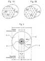
- a holey fibrehas a solid core ( Figure 1A of the accompanying drawings) or a hollow core ( Figure 1B of the accompanying drawings) surrounded by a holey cladding region.
- the holey fibres illustratedhave a hole structure characterised by a hole diameter, d, and an interhole spacing, i.e. pitch, ⁇ .
- a holey fibre structureis fabricated by stacking tubular capillaries in a hexagonal close packed array within a larger tube that forms an outer jacket or casing containing the capillaries.
- a solid core holey fibreas in Figure 1A, one of the tubular capillaries is removed from the stack and replaced with a solid rod of the same outer dimensions.
- a hollow core holey fibreas in Figure 1B, a number of capillaries in the centre of the stack are removed.
- the fibre stackis then drawn into a preform by a caning procedure and then placed in a fibre drawing tower and drawn into fibre.
- the finished holey fibre structureis then characterised by an inner core (solid or hollow) surrounded by a holey cladding. Fabrication of holey fibres is discussed further in the literature [3][4].
- Fibres with such small hole feature sizeshave a number of interesting and unique properties such as anomalous dispersion at short wavelength, high optical non-linearity and the possibility for large evanescent fields in air.
- FIG. 2 of the accompanying drawingsshows a thick wall silica outer jacket 1 defining an inner cylindrical space in which is placed two rings of silica cladding capillaries 2 which are arranged concentrically about a centrally placed solid silica core 4.
- the inner space of the outer jacket 1is additionally sleeved by a vycore tube 3.
- the dimensions included on the top of the figureare exemplary preform dimensions in millimetres, whereas the dimensions at the bottom of the figure are target fibre dimensions in microns.
- Use of a thick wall outer jackethas the advantage of allowing the number of capillaries required to be greatly reduced.
- the thick wall outer jacket approachhas been demonstrated by other groups. However, in the experience of the present inventors at least, it has proved difficult to reliably and controllably retain small hole features during the fibre pulling stage of the fabrication process when using such thick walled outer jacket structures. It is believed that this problem is attributable to the relatively small ratio of air to glass in the thick-walled structure, and to the relatively large thermal mass of the glass of the outer jacket as the preform is melted in the drawing tower furnace during the fibre drawing process.
- an optical fibre structurecomprising a holey fibre arranged in a holey outer support structure according to claim 1.
- the holey outer support structurepreferably has a lateral feature size at least five or ten times greater than that of the holey fibre.
- the holey fibremay have a solid or hollow core surrounded by a holey cladding which may comprise cavities arranged in a plurality of rings concentrically about the core, e.g. 2-6 or more rings.
- the holey outer support structureis conveniently made of an arrangement of tubular structures, each of roughly the same lateral dimensions as the holey fibre.
- the lateral dimensionsare preferably between one fifth and five times that of the holey fibre, preferably between one half and twice that of the holey fibre.
- the holey outer support structuremay conveniently further comprise an outer jacket surrounding the tubular structures.
- An optical fibre structure embodying the inventionpossesses a microstructured transverse cross section in which the microstructuring in the holey fibre itself is on the scale of the wavelength of the light guided by the holey fibre, but is on a considerably coarser scale within an outer holey structure supporting the holey fibre (e.g. five times, ten times or a greater multiple of the wavelength).
- an optical fibre preformcomprising: (a) a core rod; (b) a plurality of cladding capillaries arranged around the core rod; (c) an inner jacket containing the cladding capillaries; and (d) a plurality of support capillaries arranged around the inner jacket.
- the preformmay further comprise an outer jacket containing the support capillaries.
- a method of making a holey fibre preformcomprising: (a) arranging a core rod and a plurality of cladding capillaries within a first jacket; (b) arranging the first jacket and a plurality of support capillaries in a second jacket to form a tube assembly; and (c) reducing the tube assembly to a preform.
- the support capillariesmay be arranged within an outer j acket.
- a method of making a holey fibrecomprising: (a) making a holey fibre preform according to the method of the third aspect; and (b) drawing a holey fibre from the preform.
- the support capillariesmay be arranged within an outer jacket.
- a method of guiding lightin a holey fibre structure comprising a holey fibre arranged in a holey outer support structure, the light having a mode field extending in a cross-sectional plane through the holey fibre, wherein the mode field is mainly confined in the holey fibre.
- the structureis designed so that the holey outer support structure does not contribute in any significant way to the optical guiding properties of the holey fibre contained within it.
- the mode fieldhas less than one of 10%, 5%, 2%, 1%, 0.5% and 0.01% of its power extending beyond the holey fibre into the holey outer support structure.
- Figure 3is an end view of a holey fibre preform according to this approach.
- the preformcomprises an inner cane 14 containing the elements that will form the holey fibre after fibre drawing.
- the central regioncomprises a solid core rod surrounded by a plurality of small capillaries arranged around the core rod, which ultimately form the holey cladding of the fibre.
- the rod and capillariesare retained in an inner jacket which forms the outer surface of the inner cane.
- the small cladding capillariesare arranged in one or more rings concentrically about the core rod.
- at least two rings of cladding capillarieswill be needed for most holey fibre applications. In fact, two is a preferred number, since it represents the smallest number of rings for providing the optical properties desired in many applications.
- the number of ringsmay be greater, e.g. three, four, five, six or more, but it should be borne in mind that very large numbers of capillaries will present fabrication difficulties, as described further above in relation to the prior art.
- the inner cane 14is supported by a plurality of relatively large-scale support capillaries 12 arranged around the inner cane.
- the support capillariesare retained in a relatively thin outer jacket 10.
- the outer jacketcould be dispensed with and the support capillaries fused together at the top and bottom prior to pulling to hold them together.
- the support capillarieshave an outside diameter approximately the same as the outside diameter of the inner cane 14, so that the inner cane can be arranged with the support capillaries in a hexagonal close packed array. More generally, it is convenient for the support capillaries to be of the same order of magnitude of lateral dimension as the inner cane.
- the support capillariesPreferably have lateral dimensions of between one fifth and five times that of the inner cane, more especially between one half and twice that of the inner jacket.
- the capillariescan be made in a variety of ways.
- the starting point for the capillariesis a large-scale tube.
- the large-scale tubescan be produced by: extrusion, milling and drilling, polishing, piercing, spin/rotational casting, other casting methods (e.g. built-in casting), compression moulding, direct bonding etc.
- the tubesare then caned down using a fibre draw tower to the dimensions required for the preform assembly.
- the thermal mass of the supporting structure used to bulk out the central region of the holey fibreis significantly reduced in comparison to a thick-wall outer jacket used in the prior art. It is thus easier to pull the preform and to retain the desired form of microstructure within the vicinity of the central holey fibre region.
- the completed preformis then ready for the next main stage of fibre drawing.
- the preformis placed in a fibre drawing tower.
- Fibre drawingis performed by the controlled heating and/or cooling of the silica or other glass through a viscosity range of around 10 6 poise. It is useful to monitor the diameter and tension of the fibre as it is being drawn and use the data thus acquired in an automatic feedback loop to control the preform feed speed, the fibre draw speed and/or other parameters related to the furnace in order to yield a uniform fibre diameter.
- a principal component of the drawing tower used to pull the preform into fibre formis a heat source, which may be a graphite resistance heater or a radio-frequency (RF) furnace.
- a heat sourcewhich may be a graphite resistance heater or a radio-frequency (RF) furnace.
- the fibre drawing temperaturemust soften the glass to provide a viscosity for which the glass can deform and stretch into a fibre without crystallisation.
- the softening of the glassmust not be so great that the crucial internal structure, i.e. the holes, collapse and flow together. Cooling is provided above and below the furnace's hot zone. The cooling keeps the glass outside the hot zone cooled to below its crystallisation temperature.
- Figure 4is a cross-section of a holey fibre structure according to an example of the invention which has been drawn from a preform generally of the kind illustrated in Figure 3.
- the drawn holey fibre structurecomprises a holey fibre 20 arranged in a holey outer support structure.
- the holey outer support structurecomprises an arrangement of tubular structures 22 laterally bounded by a relatively thin wall outer jacket 24 of outer diameter approximately equal to 250 ⁇ m.
- the outer dimensionsis preferably at least 80 ⁇ m.
- a preferred range of outer dimensionsis 80 ⁇ m to between 1-5 mm.
- the internal structure of the holey fibre at the centre of the structureis just visible in Figure 4, but is better seen in the enlarged view of Figure 5.
- FIG 5is a magnified view of the centre region of the holey fibre structure shown in Figure 4.
- the holey fibrecomprises a solid core 32 surrounded by a cladding 30 comprising hole rings generally concentrically arranged about the core. It will be understood that the holes will not form perfect circles around the core owing to the realities of the drawing process. The term concentric is thus not to be construed with any geometric rigour in this document.
- the claddingis in turn surrounded by the remnant 28 of the outer jacket of the preform.
- the corecould be hollow instead of solid, for example for photonic crystal fibre.
- the large change in lateral feature size between the holey fibre on the one hand and the support tubes on the other handis apparent.
- the support capillariespreferably have an outside diameter at least five or ten times greater than that of the holey fibre 20.
- the holey fibre 20has an outside diameter somewhat smaller than that of the support capillaries 22. Generally, these two lateral dimensions will be comparable. Specifically, it is preferred that the tubular support structures 22 have lateral dimensions of between one fifth and five times that of the holey fibre, more especially between one half and twice that of the holey fibre.
- Figure 6is a cross-section of the central region of another holey fibre structure according to the invention.
- a larger number of cladding capillarieswere used in the preform to form a larger number of generally concentric hole rings in the cladding. Otherwise the example of Figure 6 will be understood from the previous description.
- the above examplesuses tubes as a basis for the holey fibre preform, it will be understood that other shapes could be used either in the holey support structure or for the holey cladding part of the structure. It is sufficient that the holey outer support structure and holey cladding have a sufficient number of gaps or cavities to provide the desired properties. It will also be understood that the hole arrangement in the support structure will generally have no bearing on the optical properties of the fibre, since the fibre waveguide modes will usually have no significant power outside the holey cladding. Periodic or aperiodic arrangements may be used. It will also be understood that the holes in the cladding need not be periodic, unless the fibre is intended to have photonic crystal effects.
- Holey fibre structures according to the inventionmay find application in many of the areas previously proposed to be of interest for holey fibres.
- One applicationis sensing. It has been proposed that a fluid, i.e. gas or liquid, is present in the fibre cavities. A property of the fluid is then sensed by its effect on that part of the optical mode, generally an evanescent wave part, which propagates in the holey cladding region.
- a fluidi.e. gas or liquid
- holey fibresAnother application suggested for holey fibres is for low-loss telecommunication fibre. Propagation losses may be reduced in a holey fibre, by virtue of the lower losses associated with the holes relative to the glass regions of the fibre. More fundamentally, a holey fibre with a photonic band gap could reduce losses through photonic crystal effects.
Landscapes
- Physics & Mathematics (AREA)
- Chemical & Material Sciences (AREA)
- Optics & Photonics (AREA)
- Engineering & Computer Science (AREA)
- General Physics & Mathematics (AREA)
- Crystallography & Structural Chemistry (AREA)
- Life Sciences & Earth Sciences (AREA)
- General Life Sciences & Earth Sciences (AREA)
- Geochemistry & Mineralogy (AREA)
- Manufacturing & Machinery (AREA)
- Materials Engineering (AREA)
- Organic Chemistry (AREA)
- Optical Fibers, Optical Fiber Cores, And Optical Fiber Bundles (AREA)
- Manufacture, Treatment Of Glass Fibers (AREA)
Description
- 1 .
- T A Birks et al: Electronic Letters, vol. 31, pages 1941-1943 (1995)
- 2.
- US 5,802,236: DiGiovanni et al: Lucent Technologies Inc.
- 3.
- P J Bennett et al: Optics Letters, vol. 24, pages 1203-1205 (1999)
- 4.
- P J Bennett et al: CLEO '99, CWF64, page 293
Claims (23)
- An optical fibre structure comprising a holey fibre (20) surrounded by a first tubular structure and arranged in a holey outersupport structure,wherein the holey outer support structure comprises a plurality of further tubular structures (22,32)arranged around the first tubular structure.
- An optical fibre structure according to claim 1, wherein the further tubular structuresof the holey outer support structure have a lateral size at least five times greater than alateral size of holes in the holey fibre (20).
- An optical fibre structure according to claim 1, wherein the further tubular structuresof the holey outer support structure have a lateral size at least ten times greater than alateral size of holes in the holey fibre (20).
- An optical fibre structure according to any one of the preceding claims,wherein the holey fibre (20) comprises a solid or hollow core surrounded by a holeycladding.
- An optical fibre structure according to claim 4, wherein the holey claddingcomprises cavities arranged in a plurality of rings concentrically about the core.
- An optical fibre structure according to claim 5, wherein the number of rings istwo.
- An optical fibre structure according to claim 5, wherein the number of rings isthree, four, five or six.
- An optical fibre structure according to any one of claims 1 to 7, wherein thefurther tubular structures of the holey outer support structure have lateral dimensions ofbetween one fifth and five times that of the holey fibre (20).
- An optical fibre structure according to any one of claims 1 to 7, wherein thefurther tubular structures of the holey outer support structure have lateral dimensions ofbetween one half and twice that of the holey fibre (20).
- An optical fibre structure according to any one of the preceding claims,
wherein the holey outer support structure further comprises an outer jacketsurrounding the arrangement of further tubular structures. - An optical fibre preform comprising:(a) a core rod;(b) a plurality of cladding capillaries arranged around the core rod;(c) an inner jacket containing the cladding capillaries; and(d) a plurality of support capillaries (12) arranged around the inner jacket;
- An optical fibre preform according to claim 11, further comprising an outerjacket containing the support capillaries.
- An optical fibre preform according to claim 11 or 12, wherein the supportcapillaries have lateral dimensions between one fifth and five times that of the innerjacket
- An optical fibre preform according to claim 11 or 12, wherein the supportcapillaries have lateral dimensions between one half and twice that of the inner jacket.
- An optical fibre preform according to any one of claims 11 to 14, wherein thecore rod is hollow.
- An optical fibre preform according to any one of claims 11 to 14, wherein thecore rod is solid.
- An optical fibre preform according to any one of claims 11 to 16, wherein thecladding capillaries are arranged in a plurality of rings concentrically about the corerod.
- An optical fibre preform according to claim 17, wherein the number of rings istwo.
- An optical fibre preform according to claim 17, wherein the number of rings isthree, four, five or six.
- A method of making a holey fibre preform comprising:(a) arranging a core rod and a plurality of cladding capillaries within a firstjacket;(b) arranging the first jacket and a plurality of support capillaries (12) to form atube assembly; and(c) reducing the tube assembly to a preform.
- A method of making a holey fibre comprising:(a) making a holey fibre preform according to the method of claim 20; and(b) drawing a holey fibre from the preform.
- A method according to claim 20 or 21, wherein the support capillaries arearranged within an outer jacket.
- A method of guiding light along an optical fibre structure, the methodcomprising using an optical fibre structure comprising a holey fibre (20) arranged in aholey outer support structure, wherein the holey fibre is surrounded by a first tubularstructure and wherein the holey outer support structure comprises a plurality offurther tubular structures arranged around the first tubular structure, and arranging the light tohave a mode field extending in a cross-sectional plane through the holey fibre,wherein the mode field is confined in the holey fibre so as to have less than one of 10%, 5%, 2%, 1%, 0.5% and 0:01% of its power extending beyond the holey fibreinto the holey outer support structure.
Priority Applications (1)
| Application Number | Priority Date | Filing Date | Title |
|---|---|---|---|
| EP01954222AEP1309890B1 (en) | 2000-08-18 | 2001-08-10 | Holey optical fibres, preforms and manufacturing methods |
Applications Claiming Priority (6)
| Application Number | Priority Date | Filing Date | Title |
|---|---|---|---|
| EP00307090 | 2000-08-18 | ||
| EP00307090 | 2000-08-18 | ||
| US23045800P | 2000-09-06 | 2000-09-06 | |
| US230458P | 2000-09-06 | ||
| PCT/GB2001/003618WO2002016980A1 (en) | 2000-08-18 | 2001-08-10 | Holey optical fibres |
| EP01954222AEP1309890B1 (en) | 2000-08-18 | 2001-08-10 | Holey optical fibres, preforms and manufacturing methods |
Publications (2)
| Publication Number | Publication Date |
|---|---|
| EP1309890A1 EP1309890A1 (en) | 2003-05-14 |
| EP1309890B1true EP1309890B1 (en) | 2004-11-03 |
Family
ID=37515862
Family Applications (1)
| Application Number | Title | Priority Date | Filing Date |
|---|---|---|---|
| EP01954222AExpired - LifetimeEP1309890B1 (en) | 2000-08-18 | 2001-08-10 | Holey optical fibres, preforms and manufacturing methods |
Country Status (9)
| Country | Link |
|---|---|
| EP (1) | EP1309890B1 (en) |
| JP (1) | JP2004507783A (en) |
| CN (1) | CN1447929A (en) |
| AR (1) | AR030359A1 (en) |
| AT (1) | ATE281657T1 (en) |
| AU (1) | AU2001276565A1 (en) |
| BR (1) | BR0113332A (en) |
| DE (1) | DE60106937T2 (en) |
| WO (1) | WO2002016980A1 (en) |
Families Citing this family (4)
| Publication number | Priority date | Publication date | Assignee | Title |
|---|---|---|---|---|
| US7321712B2 (en) | 2002-12-20 | 2008-01-22 | Crystal Fibre A/S | Optical waveguide |
| AU2003290349A1 (en) | 2002-12-20 | 2004-07-14 | Blazephotonics Limited | Photonic bandgap optical waveguide |
| GB2562688B (en)* | 2013-09-20 | 2019-06-19 | Univ Southampton | Methods of manufacturing hollow-core photonic bandgap fibers. |
| CN109143460B (en)* | 2018-09-12 | 2019-08-30 | 华中科技大学 | A kind of negative curvature hollow core fiber and its preparation method |
Family Cites Families (3)
| Publication number | Priority date | Publication date | Assignee | Title |
|---|---|---|---|---|
| US5802236A (en)* | 1997-02-14 | 1998-09-01 | Lucent Technologies Inc. | Article comprising a micro-structured optical fiber, and method of making such fiber |
| EP0810453B1 (en)* | 1996-05-31 | 2001-10-10 | Lucent Technologies Inc. | Article comprising a micro-structured optical fiber, and method of making such fiber |
| WO1999064904A1 (en)* | 1998-06-09 | 1999-12-16 | Crystal Fibre A/S | A photonic band gap fibre |
- 2001
- 2001-08-10ATAT01954222Tpatent/ATE281657T1/ennot_activeIP Right Cessation
- 2001-08-10WOPCT/GB2001/003618patent/WO2002016980A1/enactiveIP Right Grant
- 2001-08-10BRBR0113332-2Apatent/BR0113332A/ennot_activeApplication Discontinuation
- 2001-08-10JPJP2002522016Apatent/JP2004507783A/enactivePending
- 2001-08-10AUAU2001276565Apatent/AU2001276565A1/ennot_activeAbandoned
- 2001-08-10EPEP01954222Apatent/EP1309890B1/ennot_activeExpired - Lifetime
- 2001-08-10DEDE60106937Tpatent/DE60106937T2/ennot_activeExpired - Fee Related
- 2001-08-10CNCN01814302Apatent/CN1447929A/enactivePending
- 2001-08-16ARARP010103914Apatent/AR030359A1/enunknown
Also Published As
| Publication number | Publication date |
|---|---|
| DE60106937D1 (en) | 2004-12-09 |
| ATE281657T1 (en) | 2004-11-15 |
| JP2004507783A (en) | 2004-03-11 |
| CN1447929A (en) | 2003-10-08 |
| AU2001276565A1 (en) | 2002-03-04 |
| DE60106937T2 (en) | 2006-03-02 |
| BR0113332A (en) | 2003-07-15 |
| EP1309890A1 (en) | 2003-05-14 |
| AR030359A1 (en) | 2003-08-20 |
| WO2002016980A1 (en) | 2002-02-28 |
Similar Documents
| Publication | Publication Date | Title |
|---|---|---|
| US6968107B2 (en) | Holey optical fibres | |
| van Eijkelenborg et al. | Recent progress in microstructured polymer optical fibre fabrication and characterisation | |
| CN111812772B (en) | Hollow polarization-maintaining anti-resonance optical fiber and preparation method thereof | |
| JP4554199B2 (en) | Plastic photonic crystal fiber for terahertz wave transmission and manufacturing method thereof | |
| EP1153325B1 (en) | Photonic crystal fibresand methods of manufacturing | |
| US7155097B2 (en) | Fabrication of microstructured fibres | |
| Pickrell et al. | Novel techniques for the fabrication of holey optical fibers | |
| US7295740B2 (en) | High air fraction photonic band gap fibers | |
| US20050238301A1 (en) | Method of drawing microstructured glass optical fibres from a preform | |
| US20100104869A1 (en) | Photonic Crystal Fibers and Methods for Manufacturing the Same | |
| JP2007534592A (en) | Optical fibers, their preforms, and their manufacturing methods and equipment | |
| US20040033043A1 (en) | Dispersion tailoring in optical fibres | |
| EP1086391A1 (en) | Microstructured optical fibres | |
| US20050147366A1 (en) | Constructing preforms from capillaries and canes | |
| Russell | Photonic crystal fibers: a historical account | |
| WO2002026648A1 (en) | Multi-component all glass photonic band-gap fiber | |
| EP1309890B1 (en) | Holey optical fibres, preforms and manufacturing methods | |
| JP2004020836A (en) | Optical fiber and manufacturing method thereof | |
| US8033142B2 (en) | Method for fabricating an optical fiber, preform for fabricating an optical fiber, optical fiber and apparatus | |
| WO2004053550A1 (en) | Improvements relating to photonic crystal fibres | |
| Birks | Hampshire (GB) | |
| Pickrell et al. | Random hole optical fibers | |
| JP2003107255A (en) | Single mode optical fiber | |
| Bjarklev et al. | Fabrication of photonic crystal fibres | |
| Tian et al. | Design and fabrication of embedded two elliptical cores hollow fiber |
Legal Events
| Date | Code | Title | Description |
|---|---|---|---|
| PUAI | Public reference made under article 153(3) epc to a published international application that has entered the european phase | Free format text:ORIGINAL CODE: 0009012 | |
| 17P | Request for examination filed | Effective date:20030218 | |
| AK | Designated contracting states | Designated state(s):AT BE CH CY DE DK ES FI FR GB GR IE IT LI LU MC NL PT SE TR | |
| AX | Request for extension of the european patent | Extension state:AL LT LV MK RO SI | |
| GRAP | Despatch of communication of intention to grant a patent | Free format text:ORIGINAL CODE: EPIDOSNIGR1 | |
| RTI1 | Title (correction) | Free format text:HOLEY OPTICAL FIBRES, PREFORMS AND MANUFACTURING METHODS | |
| RTI1 | Title (correction) | Free format text:HOLEY OPTICAL FIBRES, PREFORMS AND MANUFACTURING METHODS | |
| GRAS | Grant fee paid | Free format text:ORIGINAL CODE: EPIDOSNIGR3 | |
| GRAA | (expected) grant | Free format text:ORIGINAL CODE: 0009210 | |
| AK | Designated contracting states | Kind code of ref document:B1 Designated state(s):AT BE CH CY DE DK ES FI FR GB GR IE IT LI LU MC NL PT SE TR | |
| PG25 | Lapsed in a contracting state [announced via postgrant information from national office to epo] | Ref country code:TR Free format text:LAPSE BECAUSE OF FAILURE TO SUBMIT A TRANSLATION OF THE DESCRIPTION OR TO PAY THE FEE WITHIN THE PRESCRIBED TIME-LIMIT Effective date:20041103 Ref country code:NL Free format text:LAPSE BECAUSE OF FAILURE TO SUBMIT A TRANSLATION OF THE DESCRIPTION OR TO PAY THE FEE WITHIN THE PRESCRIBED TIME-LIMIT Effective date:20041103 Ref country code:FI Free format text:LAPSE BECAUSE OF FAILURE TO SUBMIT A TRANSLATION OF THE DESCRIPTION OR TO PAY THE FEE WITHIN THE PRESCRIBED TIME-LIMIT Effective date:20041103 Ref country code:BE Free format text:LAPSE BECAUSE OF FAILURE TO SUBMIT A TRANSLATION OF THE DESCRIPTION OR TO PAY THE FEE WITHIN THE PRESCRIBED TIME-LIMIT Effective date:20041103 Ref country code:LI Free format text:LAPSE BECAUSE OF FAILURE TO SUBMIT A TRANSLATION OF THE DESCRIPTION OR TO PAY THE FEE WITHIN THE PRESCRIBED TIME-LIMIT Effective date:20041103 Ref country code:AT Free format text:LAPSE BECAUSE OF FAILURE TO SUBMIT A TRANSLATION OF THE DESCRIPTION OR TO PAY THE FEE WITHIN THE PRESCRIBED TIME-LIMIT Effective date:20041103 Ref country code:CH Free format text:LAPSE BECAUSE OF FAILURE TO SUBMIT A TRANSLATION OF THE DESCRIPTION OR TO PAY THE FEE WITHIN THE PRESCRIBED TIME-LIMIT Effective date:20041103 | |
| REG | Reference to a national code | Ref country code:GB Ref legal event code:FG4D | |
| REG | Reference to a national code | Ref country code:CH Ref legal event code:EP | |
| REF | Corresponds to: | Ref document number:60106937 Country of ref document:DE Date of ref document:20041209 Kind code of ref document:P | |
| REG | Reference to a national code | Ref country code:IE Ref legal event code:FG4D | |
| PG25 | Lapsed in a contracting state [announced via postgrant information from national office to epo] | Ref country code:SE Free format text:LAPSE BECAUSE OF FAILURE TO SUBMIT A TRANSLATION OF THE DESCRIPTION OR TO PAY THE FEE WITHIN THE PRESCRIBED TIME-LIMIT Effective date:20050203 Ref country code:GR Free format text:LAPSE BECAUSE OF FAILURE TO SUBMIT A TRANSLATION OF THE DESCRIPTION OR TO PAY THE FEE WITHIN THE PRESCRIBED TIME-LIMIT Effective date:20050203 Ref country code:DK Free format text:LAPSE BECAUSE OF FAILURE TO SUBMIT A TRANSLATION OF THE DESCRIPTION OR TO PAY THE FEE WITHIN THE PRESCRIBED TIME-LIMIT Effective date:20050203 | |
| PG25 | Lapsed in a contracting state [announced via postgrant information from national office to epo] | Ref country code:ES Free format text:LAPSE BECAUSE OF FAILURE TO SUBMIT A TRANSLATION OF THE DESCRIPTION OR TO PAY THE FEE WITHIN THE PRESCRIBED TIME-LIMIT Effective date:20050214 | |
| NLV1 | Nl: lapsed or annulled due to failure to fulfill the requirements of art. 29p and 29m of the patents act | ||
| REG | Reference to a national code | Ref country code:CH Ref legal event code:PL | |
| PG25 | Lapsed in a contracting state [announced via postgrant information from national office to epo] | Ref country code:LU Free format text:LAPSE BECAUSE OF NON-PAYMENT OF DUE FEES Effective date:20050810 Ref country code:CY Free format text:LAPSE BECAUSE OF FAILURE TO SUBMIT A TRANSLATION OF THE DESCRIPTION OR TO PAY THE FEE WITHIN THE PRESCRIBED TIME-LIMIT Effective date:20050810 Ref country code:IE Free format text:LAPSE BECAUSE OF NON-PAYMENT OF DUE FEES Effective date:20050810 | |
| PG25 | Lapsed in a contracting state [announced via postgrant information from national office to epo] | Ref country code:MC Free format text:LAPSE BECAUSE OF NON-PAYMENT OF DUE FEES Effective date:20050831 | |
| PLBE | No opposition filed within time limit | Free format text:ORIGINAL CODE: 0009261 | |
| STAA | Information on the status of an ep patent application or granted ep patent | Free format text:STATUS: NO OPPOSITION FILED WITHIN TIME LIMIT | |
| ET | Fr: translation filed | ||
| 26N | No opposition filed | Effective date:20050804 | |
| REG | Reference to a national code | Ref country code:IE Ref legal event code:MM4A | |
| PGFP | Annual fee paid to national office [announced via postgrant information from national office to epo] | Ref country code:IT Payment date:20060831 Year of fee payment:6 | |
| PGFP | Annual fee paid to national office [announced via postgrant information from national office to epo] | Ref country code:FR Payment date:20060911 Year of fee payment:6 | |
| PGFP | Annual fee paid to national office [announced via postgrant information from national office to epo] | Ref country code:GB Payment date:20060914 Year of fee payment:6 | |
| PGFP | Annual fee paid to national office [announced via postgrant information from national office to epo] | Ref country code:DE Payment date:20060925 Year of fee payment:6 | |
| PG25 | Lapsed in a contracting state [announced via postgrant information from national office to epo] | Ref country code:PT Free format text:LAPSE BECAUSE OF NON-PAYMENT OF DUE FEES Effective date:20050403 | |
| GBPC | Gb: european patent ceased through non-payment of renewal fee | Effective date:20070810 | |
| REG | Reference to a national code | Ref country code:FR Ref legal event code:ST Effective date:20080430 | |
| PG25 | Lapsed in a contracting state [announced via postgrant information from national office to epo] | Ref country code:DE Free format text:LAPSE BECAUSE OF NON-PAYMENT OF DUE FEES Effective date:20080301 | |
| PG25 | Lapsed in a contracting state [announced via postgrant information from national office to epo] | Ref country code:FR Free format text:LAPSE BECAUSE OF NON-PAYMENT OF DUE FEES Effective date:20070831 | |
| PG25 | Lapsed in a contracting state [announced via postgrant information from national office to epo] | Ref country code:GB Free format text:LAPSE BECAUSE OF NON-PAYMENT OF DUE FEES Effective date:20070810 | |
| PG25 | Lapsed in a contracting state [announced via postgrant information from national office to epo] | Ref country code:IT Free format text:LAPSE BECAUSE OF NON-PAYMENT OF DUE FEES Effective date:20070810 |