EP1306064A1 - Instrument for inserting an intervertebral prosthesis - Google Patents
Instrument for inserting an intervertebral prosthesisDownload PDFInfo
- Publication number
- EP1306064A1 EP1306064A1EP01125793AEP01125793AEP1306064A1EP 1306064 A1EP1306064 A1EP 1306064A1EP 01125793 AEP01125793 AEP 01125793AEP 01125793 AEP01125793 AEP 01125793AEP 1306064 A1EP1306064 A1EP 1306064A1
- Authority
- EP
- European Patent Office
- Prior art keywords
- prosthesis
- instrument
- instrument body
- longitudinal direction
- holder
- Prior art date
- Legal status (The legal status is an assumption and is not a legal conclusion. Google has not performed a legal analysis and makes no representation as to the accuracy of the status listed.)
- Withdrawn
Links
Images


Classifications
- A—HUMAN NECESSITIES
- A61—MEDICAL OR VETERINARY SCIENCE; HYGIENE
- A61F—FILTERS IMPLANTABLE INTO BLOOD VESSELS; PROSTHESES; DEVICES PROVIDING PATENCY TO, OR PREVENTING COLLAPSING OF, TUBULAR STRUCTURES OF THE BODY, e.g. STENTS; ORTHOPAEDIC, NURSING OR CONTRACEPTIVE DEVICES; FOMENTATION; TREATMENT OR PROTECTION OF EYES OR EARS; BANDAGES, DRESSINGS OR ABSORBENT PADS; FIRST-AID KITS
- A61F2/00—Filters implantable into blood vessels; Prostheses, i.e. artificial substitutes or replacements for parts of the body; Appliances for connecting them with the body; Devices providing patency to, or preventing collapsing of, tubular structures of the body, e.g. stents
- A61F2/02—Prostheses implantable into the body
- A61F2/30—Joints
- A61F2/46—Special tools for implanting artificial joints
- A61F2/4603—Special tools for implanting artificial joints for insertion or extraction of endoprosthetic joints or of accessories thereof
- A61F2/4611—Special tools for implanting artificial joints for insertion or extraction of endoprosthetic joints or of accessories thereof of spinal prostheses
- A—HUMAN NECESSITIES
- A61—MEDICAL OR VETERINARY SCIENCE; HYGIENE
- A61B—DIAGNOSIS; SURGERY; IDENTIFICATION
- A61B17/00—Surgical instruments, devices or methods
- A61B17/02—Surgical instruments, devices or methods for holding wounds open, e.g. retractors; Tractors
- A61B17/025—Joint distractors
- A—HUMAN NECESSITIES
- A61—MEDICAL OR VETERINARY SCIENCE; HYGIENE
- A61B—DIAGNOSIS; SURGERY; IDENTIFICATION
- A61B17/00—Surgical instruments, devices or methods
- A61B17/00234—Surgical instruments, devices or methods for minimally invasive surgery
- A61B2017/00238—Type of minimally invasive operation
- A61B2017/00261—Discectomy
- A—HUMAN NECESSITIES
- A61—MEDICAL OR VETERINARY SCIENCE; HYGIENE
- A61B—DIAGNOSIS; SURGERY; IDENTIFICATION
- A61B17/00—Surgical instruments, devices or methods
- A61B17/02—Surgical instruments, devices or methods for holding wounds open, e.g. retractors; Tractors
- A61B17/025—Joint distractors
- A61B2017/0256—Joint distractors for the spine
- A—HUMAN NECESSITIES
- A61—MEDICAL OR VETERINARY SCIENCE; HYGIENE
- A61F—FILTERS IMPLANTABLE INTO BLOOD VESSELS; PROSTHESES; DEVICES PROVIDING PATENCY TO, OR PREVENTING COLLAPSING OF, TUBULAR STRUCTURES OF THE BODY, e.g. STENTS; ORTHOPAEDIC, NURSING OR CONTRACEPTIVE DEVICES; FOMENTATION; TREATMENT OR PROTECTION OF EYES OR EARS; BANDAGES, DRESSINGS OR ABSORBENT PADS; FIRST-AID KITS
- A61F2/00—Filters implantable into blood vessels; Prostheses, i.e. artificial substitutes or replacements for parts of the body; Appliances for connecting them with the body; Devices providing patency to, or preventing collapsing of, tubular structures of the body, e.g. stents
- A61F2/02—Prostheses implantable into the body
- A61F2/30—Joints
- A61F2/46—Special tools for implanting artificial joints
- A61F2/4603—Special tools for implanting artificial joints for insertion or extraction of endoprosthetic joints or of accessories thereof
- A61F2002/4622—Special tools for implanting artificial joints for insertion or extraction of endoprosthetic joints or of accessories thereof having the shape of a forceps or a clamp
- A—HUMAN NECESSITIES
- A61—MEDICAL OR VETERINARY SCIENCE; HYGIENE
- A61F—FILTERS IMPLANTABLE INTO BLOOD VESSELS; PROSTHESES; DEVICES PROVIDING PATENCY TO, OR PREVENTING COLLAPSING OF, TUBULAR STRUCTURES OF THE BODY, e.g. STENTS; ORTHOPAEDIC, NURSING OR CONTRACEPTIVE DEVICES; FOMENTATION; TREATMENT OR PROTECTION OF EYES OR EARS; BANDAGES, DRESSINGS OR ABSORBENT PADS; FIRST-AID KITS
- A61F2/00—Filters implantable into blood vessels; Prostheses, i.e. artificial substitutes or replacements for parts of the body; Appliances for connecting them with the body; Devices providing patency to, or preventing collapsing of, tubular structures of the body, e.g. stents
- A61F2/02—Prostheses implantable into the body
- A61F2/30—Joints
- A61F2/46—Special tools for implanting artificial joints
- A61F2/4603—Special tools for implanting artificial joints for insertion or extraction of endoprosthetic joints or of accessories thereof
- A61F2002/4625—Special tools for implanting artificial joints for insertion or extraction of endoprosthetic joints or of accessories thereof with relative movement between parts of the instrument during use
- A61F2002/4627—Special tools for implanting artificial joints for insertion or extraction of endoprosthetic joints or of accessories thereof with relative movement between parts of the instrument during use with linear motion along or rotating motion about the instrument axis or the implantation direction, e.g. telescopic, along a guiding rod, screwing inside the instrument
- A—HUMAN NECESSITIES
- A61—MEDICAL OR VETERINARY SCIENCE; HYGIENE
- A61F—FILTERS IMPLANTABLE INTO BLOOD VESSELS; PROSTHESES; DEVICES PROVIDING PATENCY TO, OR PREVENTING COLLAPSING OF, TUBULAR STRUCTURES OF THE BODY, e.g. STENTS; ORTHOPAEDIC, NURSING OR CONTRACEPTIVE DEVICES; FOMENTATION; TREATMENT OR PROTECTION OF EYES OR EARS; BANDAGES, DRESSINGS OR ABSORBENT PADS; FIRST-AID KITS
- A61F2/00—Filters implantable into blood vessels; Prostheses, i.e. artificial substitutes or replacements for parts of the body; Appliances for connecting them with the body; Devices providing patency to, or preventing collapsing of, tubular structures of the body, e.g. stents
- A61F2/02—Prostheses implantable into the body
- A61F2/30—Joints
- A61F2/46—Special tools for implanting artificial joints
- A61F2/4603—Special tools for implanting artificial joints for insertion or extraction of endoprosthetic joints or of accessories thereof
- A61F2002/4625—Special tools for implanting artificial joints for insertion or extraction of endoprosthetic joints or of accessories thereof with relative movement between parts of the instrument during use
- A61F2002/4628—Special tools for implanting artificial joints for insertion or extraction of endoprosthetic joints or of accessories thereof with relative movement between parts of the instrument during use with linear motion along or rotating motion about an axis transverse to the instrument axis or to the implantation direction, e.g. clamping
- A—HUMAN NECESSITIES
- A61—MEDICAL OR VETERINARY SCIENCE; HYGIENE
- A61F—FILTERS IMPLANTABLE INTO BLOOD VESSELS; PROSTHESES; DEVICES PROVIDING PATENCY TO, OR PREVENTING COLLAPSING OF, TUBULAR STRUCTURES OF THE BODY, e.g. STENTS; ORTHOPAEDIC, NURSING OR CONTRACEPTIVE DEVICES; FOMENTATION; TREATMENT OR PROTECTION OF EYES OR EARS; BANDAGES, DRESSINGS OR ABSORBENT PADS; FIRST-AID KITS
- A61F2/00—Filters implantable into blood vessels; Prostheses, i.e. artificial substitutes or replacements for parts of the body; Appliances for connecting them with the body; Devices providing patency to, or preventing collapsing of, tubular structures of the body, e.g. stents
- A61F2/02—Prostheses implantable into the body
- A61F2/30—Joints
- A61F2/46—Special tools for implanting artificial joints
- A61F2002/4681—Special tools for implanting artificial joints by applying mechanical shocks, e.g. by hammering
Definitions
- intervertebral prostheseseach consisting of two with one Vertebral body to be connected prosthesis plates and one arranged in between Insertion instruments are known (EP-A-333 990), which have two prosthesis holders at their front end, which each hold a prosthetic plate.
- the prosthesis holdersare connected by a parallel guide, which allows the Prosthesis plates first closely approximate each other to make them easier in to be able to introduce the narrow intervertebral space, and then (with the adjacent vertebrae) to spread apart to the prosthesis core to be able to insert. Then the prosthesis holders are brought closer together again so that the prosthesis plates keep the prosthesis core in its functional position include and the instrument is removed.
- the known The instrumentis designed as pliers that are opposite the direction of the prosthesis holders, that match the median direction of the body should be angled to prevent the insertion of the prosthesis core to be.
- Thishas several disadvantages.
- the force for Donot insert the prosthesis parts in the intervertebral space in the longitudinal direction of the instrument. Rather, it is something special Approach instrument required.
- An instrument for inserting such a prosthesisis also known (DE-U-299 16 078) by a lower pair of guide rods and an upper guide rod which is formed at the rear end are articulated and prosthesis holders at their front ends wear. They form a guideway for an expansion element. If this is propelled between them by means of a rack, spreads it pulls the rod ends apart and at the same time pushes the prosthesis core in front of him until he has reached the desired end position. Then the expansion element is withdrawn to the prosthesis plates Approaching the prosthesis core. The spreading movement is with the introduction of the prosthesis core inevitably coupled, so that the spreading process does not separately monitored and difficult to observe.
- the inventionseeks to provide an instrument that introduces one of the of the prosthesis core allows independent expansion of the prosthesis plates and its longitudinal direction when inserting the prostheses with the median direction of the body matches.
- Itrelates to an instrument for inserting an intervertebral prosthesis, the two, which can be spread apart and are connected by a parallel guide
- Has prosthesis holders for a pair of prosthesis platesThe first of these prosthesis holders is fixed to an elongated body of the instrument arranged in accordance with its longitudinal direction.
- the second prosthesis holderis by means of the parallel guide on the instrument body held.
- a semi-trailing armis provided, the first end on the instrument body movable in the longitudinal direction is articulated. Its second end is on the second prosthesis holder articulated. Its first end is in the longitudinal direction of the Instrument body movable actuator connected.
- the semi-trailing armcan be part of a parallel scissor guide.
- the semi-trailing armis symmetrical in pairs on both sides of the instrument body provided an asymmetrical and tending to tilt Avoid power transmission.
- the widthat least the transverse dimensions of the between the Prosthesis core to be inserted and a prosthesis core provided therefor Corresponds to the prosthesis core holder.
- the prosthesis corecan rely on this Easily through the instrument and through both sides Limbs are brought in guided. So that the surgeon when inserting of the prosthesis core slightly that position of the prosthesis core holder finds in which of the prosthesis core the desired position between has reached the prosthesis plates are the insertion instrument and the prosthesis core holder expediently with interacting stops provided that determine this end position.
- the actuating deviceexpediently comprises a handle and a translation facility.
- the translation devicecan, for example be formed by a threaded spindle. It has more convenience have proven to be designed as a handle lever, which is connected to a shorter working lever, the translation device forms. It is conveniently arranged so that it at the same time the lateral movement of the handle lever converts to the in Operating direction running in the longitudinal direction of the instrument body.
- the semi-trailing armcan with its first end on one on the instrument body be articulated in its longitudinal direction. Instead of of which it is also possible that it is a member of a pair of toggle levers, the actuator directly or indirectly at the knee point of the Lever pairs attacks.
- the prosthesis holders 52are fork-shaped and open at the end. Your side legs form guides for the edge of the prosthesis plates 53. They allow the prosthesis plates overcoming a frictional force in the longitudinal direction of the instrument in the Insert prosthesis holders 52 or let them slide out.
- the end of the prosthesis body 51has a striking plate 54 Impacts on this plate can cause the prosthesis plates 53 to be held by the Prosthesis holders 52 are driven between two vertebral bodies.
- the lower prosthesis holder 52A(Figs. 9 and 10) is with the instrument body 51 fixed and even connected in one piece in the example shown.
- the upper prosthesis holder 52Bis by means of a scissor assembly, which consists of scissor members 56, 57 with the instrument body 51 connected.
- the scissor assembly 56, 57is designed so that the upper Prosthesis holder 52B is only perpendicular to the lower prosthesis holder 52A and can move parallel to it.
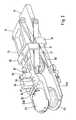
- the prosthesis holderscan be largely approximated to each other (Fig. 1) to make it easier to be driven into the intervertebral space. You can together be spread apart with the neighboring vertebral bodies (Figs. 2 and 3) to give space for the insertion of the prosthesis core 77 between the prosthesis plates 53. Then they are brought closer together again, to hold the prosthesis core in the desired position. The instrument can then be removed.
- the rear bolts 58, 59 of the scissor members 56, 57slide in elongated holes of the instrument body 51 or the plate 73, which is the upper prosthesis holder 52B continues to the rear.
- the direction of the elongated holescorresponds to the longitudinal direction of the instrument.
- the front bolts 60 the scissor members 56, 57are rigidly connected to the prosthesis holders 52.
- To spread the prosthesis holdersis a device provided the rear bolt 58 of the scissor member 57 in the longitudinal direction of the instrument moves.
- the handle lever 61is provided for this, which is pivotable on the instrument body about an axis 62 and a working lever 63, which on the rear end of a sliding block 64 acts, which is part of a T-shaped carriage 65 (Fig.
- the working lever 63, the slide 65 and the trailing arms 57thus form an arrangement for adjusting the Distance of the prosthesis holders 52. It is understood that this arrangement can also be replaced by other versions. Also recognizes one that the spreading force is not necessarily over parts of the scissor assembly needs to be exercised.
- a separate linkcan be provided for the spread.
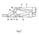
- This alternativeis illustrated in Fig. 7.
- the plate 73 on its front Endcarries the upper prosthesis holder 52 is - as in that previously described Exemplary embodiment - by means of a scissor arrangement 56,57 carried by the instrument body 51. Deviating from that version the spreader is implemented independently of the scissor arrangement.
- the links 100, 101form a toggle lever arrangement. An end this handlebar is connected to the instrument body 51 or the plate 73. Its other end forms the knee 103, at which the end of a handlebar 102 engages, the other end 104 with the actuator connected is.
- connectioncan be made as shown in Fig. 6 is shown.
- the one independent of the scissors arrangement 56.57 Spreading arrangementhas the advantage that the angle at which the handlebars 100,101 and 102 are claimed, regardless of a parallel guidance function only with a view to cheap power transmission can be measured.
- the hand lever 61is through a threaded spindle 71 with a toggle nut 72 supplements, which facilitates the process and allows the instrument temporarily set in the spread position.
- a device for ejecting the prosthesis plates 53will now be made the prosthesis holders 52 or for pressing the instrument off the Prosthesis holders or the adjacent vertebrae described.
- the prosthetic guides 52contained behind the receiving space for the prosthetic plates 53 a guide groove 80 which is in the longitudinal direction of the instrument and thus runs in the sliding direction of the prosthesis holders 52. It contains a slider 81, the front end 82 at the edge of the in the prosthesis holder located prosthesis plate and therefore as Prosthesis stop is called.
- the rear, in Fig. 2 and 3 not visible end of the slide 81is also in the longitudinal direction of the instrument guided rod 83 rigidly connected.
- the rear end of the rod 83 mounted in the instrument body 51is on, as shown in FIG.
- the stop element 84is in turn rigidly connected to a push rod 86, which is mounted in the instrument body 51 so as to be longitudinally displaceable and into one Handle 87 leads.
- a push rod 86which is mounted in the instrument body 51 so as to be longitudinally displaceable and into one Handle 87 leads.
- the movement of the handle 87only affects the slide 81 made in the lower part of the instrument, namely in the instrument body, is arranged. So that the slide 81 of both prosthesis holders move synchronously, a movement transmission device is provided.
- the rod controlling the slide 81 of the upper prosthesis holder 83is firmly connected at its rear end to a stop element 85, this as well as the stop element 84 of the lower prosthesis holder is movably guided in the longitudinal direction of the instrument.
- the lower stop element 84has on both sides towering stop legs 90 behind and adjacent legs 91 that are from the upper stop member 85 protrude on both sides.
- the neighboring onesalso lie End faces of the stop legs 90, 91 to each other. If through now Actuation of the handle 87, the lower stop element 84 with the stop legs 90 is pushed forward by their interaction with the stop legs 91 of the upper stop element also the Slide slide 81 of the upper prosthesis holder forward. The two Slider 81 thus move synchronously. Because the interacting Stop surfaces 90, 91 run perpendicular to the instrument's longitudinal direction, the synchronous movement of the slider 81 is independent of the respective one Distance between the prosthesis holders guaranteed.
- Each slide 81carries a projection 95 rigidly connected to it and a in the longitudinal direction of the slide on this led block 96, the with its end face forms the vertebral stop. If the prosthesis holders with the prosthesis plates 53 located in the space two vertebrae are driven, the end faces of the Finally, vertebral stops 96 on the ventral edges of the vertebral bodies on. By the distance of the end faces of the vertebral stops 96 from the The depth at which the prosthesis plates are determined is thus determined get into the intervertebral space. By adjusting the vertebral stops 96 on the slides 81 this depth can be changed.
Landscapes
- Health & Medical Sciences (AREA)
- Engineering & Computer Science (AREA)
- Biomedical Technology (AREA)
- Life Sciences & Earth Sciences (AREA)
- General Health & Medical Sciences (AREA)
- Veterinary Medicine (AREA)
- Heart & Thoracic Surgery (AREA)
- Transplantation (AREA)
- Orthopedic Medicine & Surgery (AREA)
- Animal Behavior & Ethology (AREA)
- Surgery (AREA)
- Public Health (AREA)
- Neurology (AREA)
- Nuclear Medicine, Radiotherapy & Molecular Imaging (AREA)
- Molecular Biology (AREA)
- Physical Education & Sports Medicine (AREA)
- Medical Informatics (AREA)
- Cardiology (AREA)
- Oral & Maxillofacial Surgery (AREA)
- Vascular Medicine (AREA)
- Prostheses (AREA)
Abstract
Description
Translated fromGermanZum Einsetzen von Zwischenwirbelprothesen, die aus zwei jeweils mit einemWirbelkörper zu verbindenden Prothesenplatten und einem dazwischen angeordnetenProthesenkern bestehen, sind Einsetzinstrumente bekannt (EP-A-333990), die an ihrem vorderen Ende zwei Prothesenhalterungen aufweisen,die jeweils eine Prothesenplatte aufnehmen. Die Prothesenhalterungen sinddurch eine Parallelführung miteinander verbunden, die es gestattet, dieProthesenplatten zunächst einander stark anzunähern, um sie leichter inden engen Zwischenwirbelraum einbringen zu können, und anschließend (mitden angrenzenden Wirbeln) auseinander zu spreizen, um den Prothesenkerneinfügen zu können. Danach nähert man die Prothesenhalterungen einanderwieder, damit die Prothesenplatten den Prothesenkern in seiner Funktionsstellungeinschließen, und das Instrument wird entfernt. Das bekannteInstrument ist als Zange ausgebildet, die gegenüber der Richtung der Prothesenhalterungen,die mit der Medianrichtung des Körpers übereinstimmensoll, abgewinkelt ist, um dem Einbringen des Prothesenkerns nicht im Wegezu sein. Dies hat verschiedene Nachteile. Insbesondere kann die Kraft zumEinbringen der Prothesenteile in den Zwischenwirbelraum nicht in Längsrichtungdes Instruments aufgebracht werden. Dafür ist vielmehr ein besonderesAnsatzinstrument erforderlich.For the insertion of intervertebral prostheses, each consisting of two with oneVertebral body to be connected prosthesis plates and one arranged in betweenInsertion instruments are known (EP-A-333990), which have two prosthesis holders at their front end,which each hold a prosthetic plate. The prosthesis holders areconnected by a parallel guide, which allows theProsthesis plates first closely approximate each other to make them easier into be able to introduce the narrow intervertebral space, and then (withthe adjacent vertebrae) to spread apart to the prosthesis coreto be able to insert. Then the prosthesis holders are brought closer togetheragain so that the prosthesis plates keep the prosthesis core in its functional positioninclude and the instrument is removed. The knownThe instrument is designed as pliers that are opposite the direction of the prosthesis holders,that match the median direction of the bodyshould be angled to prevent the insertion of the prosthesis coreto be. This has several disadvantages. In particular, the force forDo not insert the prosthesis parts in the intervertebral space in the longitudinal directionof the instrument. Rather, it is something specialApproach instrument required.
Es ist auch ein Instrument zum Einbringen einer derartigen Prothese bekannt(DE-U-299 16 078), das von einem unteren Paar von Führungsstangenund einer oberen Führungsstange gebildet ist, die am hinteren Ende aneinanderangelenkt sind und an ihren vorderen Enden Prothesenhalterungentragen. Sie bilden eine Führungsbahn für ein Spreizelement. Wenn diesesmittels einer Zahnstange zwischen ihnen vorwärts getrieben wird, spreiztes die Stangenenden auseinander und schiebt gleichzeitig den Prothesenkernvor sich her, bis dieser die gewünschte Endstellung erreicht hat.Danach wird das Spreizelement zurückgezogen, um die Prothesenplatten dem Prothesenkern zu nähern. Dabei ist die Spreizbewegung mit der Einführungdes Prothesenkerns zwangsläufig gekoppelt, so daß der Spreizvorgang nichtgesondert überwacht und nur schwer beobachtet werden kann.An instrument for inserting such a prosthesis is also known(DE-U-299 16 078) by a lower pair of guide rodsand an upper guide rod which is formed at the rear endare articulated and prosthesis holders at their front endswear. They form a guideway for an expansion element. If thisis propelled between them by means of a rack, spreadsit pulls the rod ends apart and at the same time pushes the prosthesis corein front of him until he has reached the desired end position.Then the expansion element is withdrawn to the prosthesis platesApproaching the prosthesis core. The spreading movement is with the introductionof the prosthesis core inevitably coupled, so that the spreading process does notseparately monitored and difficult to observe.
Die Erfindung sucht ein Instrument zu schaffen, das eine von dem Einbringendes Prothesenkerns unabhängige Spreizung der Prothesenplatten erlaubtund dessen Längsrichtung beim Einbringen der Prothesen mit der Medianrichtungdes Körpers übereinstimmt.The invention seeks to provide an instrument that introduces one of theof the prosthesis core allows independent expansion of the prosthesis platesand its longitudinal direction when inserting the prostheses with the median directionof the body matches.
Die erfindungsgemäße Lösung liegt in den Merkmalen des Anspruchs 1.The solution according to the invention lies in the features of
Er betrifft ein Instrument zum Einsetzen einer Zwischenwirbelprothese,das zwei durch eine Parallelführung verbundene, voneinander weg spreizbareProthesenhalterungen für ein Paar von Prothesenplatten aufweist. Dieerste dieser Prothesenhalterungen ist fest an einem langgestreckten Instrumentenkörperübereinstimmend mit dessen Längsrichtung angeordnet. Diezweite Prothesenhalterung ist vermittelst der Parallelführung an dem Instrumentenkörpergehalten. Es ist ein Schräglenker vorgesehen, dessenerstes Ende an dem Instrumentenkörper in dessen Längsrichtung beweglichangelenkt ist. Sein zweites Ende ist an dem zweiten Prothesenhalterfestachsig angelenkt. Sein erstes Ende ist mit einer in Längsrichtung desInstrumentenkörpers bewegbaren Betätigungseinrichtung verbunden. Wird dieBetätigungseinrichtung in derjenigen Richtung bewegt, in welcher das ersteEnde des Schräglenkers in Richtung zu dem Anlenkpunkt seines zweitenEndes bewegt wird, so richtet sich der Schräglenker auf und spreizt dadurchdie zweite Prothesenhalterung vom Instrumentenkörper und der erstenProthesenhalterung ab, und umgekehrt.It relates to an instrument for inserting an intervertebral prosthesis,the two, which can be spread apart and are connected by a parallel guideHas prosthesis holders for a pair of prosthesis plates. Thefirst of these prosthesis holders is fixed to an elongated body of the instrumentarranged in accordance with its longitudinal direction. Thesecond prosthesis holder is by means of the parallel guide on the instrument bodyheld. A semi-trailing arm is provided, thefirst end on the instrument body movable in the longitudinal directionis articulated. Its second end is on the second prosthesis holderarticulated. Its first end is in the longitudinal direction of theInstrument body movable actuator connected. Will theActuator moved in the direction in which the firstEnd of the semi-trailing arm towards the articulation point of its secondWhen the end is moved, the semi-trailing arm straightens up and spreadsthe second prosthesis holder from the instrument body and the firstProsthesis holder, and vice versa.
Der Schräglenker kann Teil einer Scheren-Parallelführung sein. Zweckmäßigerweiseist der Schräglenker paarig symmetrisch beiderseits des Instrumentenkörpersvorgesehen, um eine unsymmetrische und zum Verkanten neigendeKraftübertragung zu vermeiden.The semi-trailing arm can be part of a parallel scissor guide. Conveniently,the semi-trailing arm is symmetrical in pairs on both sides of the instrument bodyprovided an asymmetrical and tending to tiltAvoid power transmission.
Zweckmäßigerweise sind sämtliche den Instrumentenkörper und die zweiteProthesenhalterung verbindenden Teile außerhalb einer mittleren, inLängsrichtung des Instrumentenkörpers verlaufenden Durchtrittsöffnungangeordnet, deren Weite mindestens den Querabmessungen des zwischen dieProthesenplatten einzusetzenden Prothesenkerns und eines dafür vorgesehenenProthesenkernhalters entspricht. Der Prothesenkern kann auf dieseWeise leicht durch das Einsatzinstrument hindurch und durch dessen beidseitige Glieder geführt eingebracht werden. Damit der Operateur beim Einbringendes Prothesenkerns leicht diejenige Stellung des Prothesenkernhaltersfindet, in welcher der Prothesenkern die gewünschte Stellung zwischenden Prothesenplatten erreicht hat, sind das Einsetzinstrument undder Prothesenkernhalter zweckmäßigerweise mit zusammenwirkenden Anschlägenversehen, die diese Endstellung bestimmen.Advantageously, all of the instrument body and the secondParts connecting the prosthesis holder outside a middle, inPassage opening extending in the longitudinal direction of the instrument bodyarranged, the width at least the transverse dimensions of the between theProsthesis core to be inserted and a prosthesis core provided thereforCorresponds to the prosthesis core holder. The prosthesis core can rely on thisEasily through the instrument and through both sidesLimbs are brought in guided. So that the surgeon when insertingof the prosthesis core slightly that position of the prosthesis core holderfinds in which of the prosthesis core the desired position betweenhas reached the prosthesis plates are the insertion instrument andthe prosthesis core holder expediently with interacting stopsprovided that determine this end position.
Die Betätigungseinrichtung umfaßt zweckmäßigerweise eine Handhabe undeine Übersetzungseinrichtung. Die Übersetzungseinrichtung kann beispielsweisevon einer Gewindespindel gebildet sein. Als zweckmäßiger hat essich erwiesen, die Betätigungseinrichtung als einen Griffhebel auszubilden,der mit einem kürzeren Arbeitshebel verbunden ist, der die Übersetzungseinrichtungbildet. Er ist zweckmäßigerweise so angeordnet, daß ergleichzeitig die seitliche Bewegung des Griffhebels umwandelt in die inLängsrichtung des Instrumentenkörpers verlaufende Betätigungsrichtung.The actuating device expediently comprises a handle anda translation facility. The translation device can, for examplebe formed by a threaded spindle. It has more conveniencehave proven to be designed as a handle lever,which is connected to a shorter working lever, the translation deviceforms. It is conveniently arranged so that itat the same time the lateral movement of the handle lever converts to the inOperating direction running in the longitudinal direction of the instrument body.
Der Schräglenker kann mit seinem ersten Ende an einem am Instrumentenkörperin dessen Längsrichtung geführten Schlitten angelenkt sein. Stattdessen ist es auch möglich, daß er ein Glied eines Kniehebelpaars ist,wobei die Betätigungseinrichtung direkt oder indirekt am Kniepunkt desHebelpaars angreift.The semi-trailing arm can with its first end on one on the instrument bodybe articulated in its longitudinal direction. Instead ofof which it is also possible that it is a member of a pair of toggle levers,the actuator directly or indirectly at the knee point of theLever pairs attacks.
Die Erfindung wird im Folgenden näher unter Bezugnahme auf die Zeichnungerläutert, die ein vorteilhaftes Ausführungsbeispiel veranschaulicht. Eszeigen:
- Fig. 1
- eine Gesamtansicht des Instruments,
- Fig. 2
- eine perspektivische Ansicht des vorderenAbschnitts des Instruments von schräg oben,
- Fig. 3
- eine Seitenansicht des vorderen Abschnitts,
- Fig. 4
- eine Unteransicht des vorderen Abschnitts,
- Fig. 5
- eine Unteransicht des hinteren Teils desInstruments,
- Fig. 6
- ein Detail der Betätigungseinrichtung und
- Fig. 7
- eine alternative Ausführung der Spreizeinrichtung.
- Fig. 1
- a general view of the instrument,
- Fig. 2
- 3 shows a perspective view of the front section of the instrument obliquely from above,
- Fig. 3
- a side view of the front portion,
- Fig. 4
- a bottom view of the front section,
- Fig. 5
- a bottom view of the rear part of the instrument,
- Fig. 6
- a detail of the actuator and
- Fig. 7
- an alternative embodiment of the spreader.
Am vorderen Ende des Instrumentenkörpers 51 befinden sich zwei Halterungen52 für Prothesenplatten 53. Die Prothesenhalterungen 52 sind gabelförmigund am Ende offen. Ihre seitlichen Schenkel bilden Führungen fürden Rand der Prothesenplatten 53. Sie gestatten es, die Prothesenplattenunter Überwindung einer Reibkraft in Längsrichtung des Instruments in die Prothesenhalterungen 52 einzusetzen bzw. herausgleiten zu lassen. Am hinterenEnde besitzt der Prothesenkörper 51 eine Schlagplatte 54. DurchSchläge auf diese Platte können die Prothesenplatten 53, gehalten von denProthesenhalterungen 52, zwischen zwei Wirbelkörper getrieben werden.At the front end of the
Die untere Prothesenhalterung 52A (Fig. 9 und 10) ist mit dem Instrumentenkörper51 fest und im dargestellten Beispiel sogar einstückig verbunden.Die obere Prothesenhalterung 52B ist mittels einer Scherenanordnung,die aus Scherengliedern 56, 57 besteht, mit dem Instrumentenkörper 51verbunden. Die Scherenanordnung 56, 57 ist so gestaltet, daß die obereProthesenhalterung 52B sich ausschließlich lotrecht zur unteren Prothesenhalterung52A und parallel zu dieser bewegen kann. Die Prothesenhalterungenkönnen einander weitgehend angenähert werden (Fig. 1), um leichterin den Wirbelzwischenraum eingetrieben werden zu können. Sie können zusammenmit den benachbarten Wirbelkörpern auseinandergespreizt werden(Fig. 2 und 3), um Raum zu geben für die Einführung des Prothesenkerns 77zwischen die Prothesenplatten 53. Danach werden sie einander wieder angenähert,um den Prothesenkern in der gewünschten Stellung festzuhalten.Das Instrument kann dann abgezogen werden.The
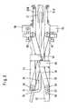
Die hinteren Bolzen 58, 59 der Scherenglieder 56, 57 gleiten in Langlöcherndes Instrumentenkörpers 51 bzw. der Platte 73, die die obere Prothesenhalterung52B nach hinten fortsetzt. Die Richtung der Langlöcherstimmt mit der Instrumentenlängsrichtung überein. Die vorderen Bolzen 60der Scherenglieder 56, 57 sind starr mit den Prothesenhalterungen 52 verbunden.Um die Prothesenhalterungen zu spreizen, ist eine Einrichtungvorgesehen, die den hinteren Bolzen 58 des Scherenglieds 57 in Längsrichtungdes Instruments verschiebt. Dafür ist der Griffhebel 61 vorgesehen,der am Instrumentenkörper um eine Achse 62 schwenkbar ist und einen Arbeitshebel63 aufweist, der auf das hintere Ende eines Gleitsteins 64wirkt, der Teil eines T-förmigen Schlittens 65 (Fig. 4 und 6) ist, andessen Querhaupt die hinteren Bolzen 58 der beiderseits angeordnetenScherenglieder 57 angelenkt sind. Der Schlitten 65 ist in Längsrichtungdes Werkzeugkörpers geführt. Man erkennt in Fig. 4, daß die parallelenKanten des Gleitsteins 64 zwischen entsprechend parallelen Kanten 66 einesAusschnitts im Instrumentenkörper geführt sind. In Fig. 3 erkenntman, daß die Enden 67 des Querhaupts in Langlöchern 68 geführt sind. Wirdder Griffhebel 61 wie beim Zusammendrücken der Hebel einer Zange an denInstrumentenkörper herangezogen, so drückt sein Arbeitshebel 63 denSchlitten 64 in Pfeilrichtung 70 (Fig. 6). Dadurch wird das hintere Ende des Scherenglieds 57 nach vorne getrieben, wodurch die Prothesenhalterungen52 auseinandergespreizt werden. Der Arbeitshebel 63, der Schlitten 65und die Schräglenker 57 bilden somit eine Anordnung zum Verstellen desAbstands der Prothesenhalterungen 52. Es versteht sich, daß diese Anordnungauch durch andere Ausführungen ersetzt werden kann. Ferner erkenntman, daß die Spreizkraft nicht unbedingt über Teile der Scherenanordnungausgeübt zu werden braucht.The
Falls der Winkel zwischen dem Schräglenker 57 und der Längsrichtung desInstruments zu klein ist für die Ausübung einer großen Spreizkraft, kannfür die Spreizung ein gesondertes Glied vorgesehen werden. Diese Alternativeist in Fig. 7 veranschaulicht. Die Platte 73, die an ihrem vorderenEnde die obere Prothesenhalterung 52 trägt, ist - wie in dem zuvor beschriebenenAusführungsbeispiel - vermittelst einer Scherenanordnung56,57 von dem Instrumentenkörper 51 getragen. Abweichend von jener Ausführungist die Spreizeinrichtung unabhängig von der Scherenanordung verwirklicht.Die Lenker 100,101 bilden eine Kniehebelanordnung. Ein Endedieser Lenker ist mit dem Instrumentenkörper 51 bzw. der Platte 73 verbunden.Ihr anderes Ende bildet das Knie 103, an dem das Ende eines Lenkers102 eingreift, dessen anderes Ende 104 mit der Betätigungseinrichtungverbunden ist. Die Verbindung kann so ausgeführt sein, wie dies inFig. 6 dargestellt ist. Die von der Scherenanordnung 56,57 unabhängigeSpreizanordnung hat den Vorteil, daß die Winkel, unter denen die Lenker100,101 und 102 beansprucht werden, ohne Rücksicht auf eine Parallelführungsfunktionlediglich im Hinblick auf eine günstige Kraftübertragungbemessen werden können.If the angle between the
Beim Spreizen der Prothesenhalterungen treten beträchtliche Kräfte auf.Deshalb ist der Handhebel 61 durch eine Gewindespindel 71 mit Knebelmutter72 ergänzt, die den Vorgang erleichtert und es gestattet, das Instrumentin der gespreizten Stellung zeitweilig festzusetzen.Significant forces occur when the prosthesis holders are spread.Therefore, the
In dieser Stellung bildet sich zwischen dem Instrumentenkörper 51 und derdie obere Prothesenhalterung 52 nach hinten fortsetzenden Platte 53 einerseitssowie zwischen den seitlichen Scherenanordnungen 56, 57 andererseitsein kanalartiger Freiraum. Durch diesen Freiraum kann mittels einesInstruments 76 der Prothesenkern 77 zwischen die Prothesenplatten 52 geführtwerden (Fig. 3). Das Instrument 76 weist einen Anschlag 75 auf, dersich an die Hinterkante 74 der Platte 73 anlegt, wenn der Prothesenkern 77 genau die vorgesehene Stellung zwischen den Prothesenplatten 52 erreichthat.In this position, between the
Es wird nun eine Einrichtung zum Auswerfen der Prothesenplatten 53 ausden Prothesenhalterungen 52 bzw. zum Abdrücken des Instruments von denProthesenhalterungen bzw. den angrenzenden Wirbeln beschrieben. Die Prothesenführungen52 enthalten hinter dem Aufnahmeraum für die Prothesenplatten53 eine Führungsnut 80, die in Instrumentenlängsrichtung und somitin der Gleitrichtung der Prothesenhalterungen 52 verläuft. Sie enthälteinen Schieber 81, dessen vorderes Ende 82 am Rand der in der Prothesenhalterungbefindlichen Prothesenplatte anschlägt und deswegen alsProthesenanschlag bezeichnet wird. Das hintere, in Fig. 2 und 3 nichtsichtbare Ende des Schiebers 81 ist mit einer ebenfalls in Instrumentenlängsrichtunggeführten Stange 83 starr verbunden. Das hintere Ende derim Instrumentenkörper 51 gelagerten Stange 83 ist, wie Fig. 4 zeigt, aneinem Anschlagelement 84 befestigt, dessen Natur später erläutert wird.Es ist ebenfalls in Längsrichtung des Instruments verschiebbar. Das Anschlagelement84 ist wiederum starr mit einer Schubstange 86 verbunden,die im Instrumentenkörper 51 längs verschieblich gelagert ist und zu einerHandhabe 87 führt. Wenn der Operateur die Handhabe 87 in Pfeilrichtungnach vorne schiebt, werden die Schubstange 86, das Anschlagelement84, die Stange 83 und der Schieber 81 nach vorne verschoben, um die Prothesenplatte53 aus der Prothesenhalterung 52 herauszuschieben. Dabeikann sich die Hand des Operateurs an einem Zapfen 88 abstützen, der festmit dem Instrumentenkörper 51 verbunden ist.A device for ejecting the
Unmittelbar wirkt sich die Bewegung der Handhabe 87 nur auf den Schieber81 aus, der im unteren Teil des Instruments, nämlich im Instrumentenkörper,angeordnet ist. Damit sich die Schieber 81 beider Prothesenhalterungensynchron bewegen, ist eine Bewegungsübertragungseinrichtung vorgesehen.Die den Schieber 81 der oberen Prothesenhalterung steuernde Stange83 ist an ihrem hinteren Ende mit einem Anschlagelement 85 fest verbunden,das ebenso wie das Anschlagelement 84 der unteren Prothesenhalterungin Instrumentenlängsrichtung beweglich geführt ist. Das untere Anschlagelement84 weist beiderseits hochragende Anschlagschenkel 90 auf, die hinterund benachbart den Schenkeln 91 liegen, die von dem oberen Anschlagelement85 beiderseits herunterragen. Wenn die Prothesenplatten 53 sich inihrer hintersten Stellung in den Prothesenhalterungen 52 befinden und dieProthesenanschläge 82 sie berühren, liegen auch die einander benachbartenStirnflächen der Anschlagschenkel 90, 91 aneinander an. Wenn nun durch Betätigung der Handhabe 87 das untere Anschlagelement 84 mit den Anschlagschenkeln90 nach vorne geschoben wird, wird durch deren Zusammenwirkenmit den Anschlagschenkeln 91 des oberen Anschlagelements auch derSchieber 81 der oberen Prothesenhalterung nach vorne geschoben. Die beidenSchieber 81 bewegen sich somit synchron. Da die zusammenwirkendenAnschlagflächen 90, 91 lotrecht zur Instrumentenlängsrichtung verlaufen,ist die synchrone Bewegung der Schieber 81 unabhängig von dem jeweiligenAbstand der Prothesenhalterungen voneinander gewährleistet.Immediately, the movement of the
Jeder Schieber 81 trägt einen starr mit ihm verbundenen Ansatz 95 sowieein in Längsrichtung des Schiebers an diesem geführtes Klötzchen 96, dasmit seiner Stirnfläche den Wirbelanschlag bildet. Wenn die Prothesenhalterungenmit den darin befindlichen Prothesenplatten 53 in den Zwischenraumzweier Wirbel eingetrieben werden, legen sich die Stirnflächen derWirbelanschläge 96 schließlich an die ventralen Kanten der Wirbelkörperan. Durch den Abstand der Stirnflächen der Wirbelanschläge 96 von denProthesenplatten wird somit die Tiefe bestimmt, in der die Prothesenplattenin den Wirbelzwischenraum gelangen. Durch Verstellen der Wirbelanschläge96 an den Schiebern 81 kann diese Tiefe verändert werden. Diesgeschieht mittels einer Gewindespindel 97, die in einer Gewindebohrungdes Ansatzes 95 geführt ist und deren Ende drehbar, aber in Längsrichtungfest mit dem Wirbelanschlag 96 verbunden ist. Durch Verdrehen der Gewindespindel97 kann somit der Operateur die Einsetztiefe der Prothesenplatten53 im Verhältnis zur ventralen Kante der zugehörigen Wirbelkörpervorherbestimmen. Dabei hilft ihm eine Skala 98.Each slide 81 carries a
Claims (9)
Translated fromGermanPriority Applications (5)
| Application Number | Priority Date | Filing Date | Title |
|---|---|---|---|
| EP01125793AEP1306064A1 (en) | 2001-10-29 | 2001-10-29 | Instrument for inserting an intervertebral prosthesis |
| DE2002125703DE10225703A1 (en) | 2001-10-29 | 2002-06-10 | Instruments for inserting an intervertebral prosthesis |
| PCT/EP2002/012025WO2003037230A2 (en) | 2001-10-29 | 2002-10-28 | Instrumentation for insertion of an inter-vertebral prosthesis |
| US10/493,888US7963971B2 (en) | 2001-10-29 | 2002-10-28 | Instrumentation for insertion of an inter-vertebral prosthesis |
| ARP020104089AR037055A1 (en) | 2001-10-29 | 2002-10-28 | INSTRUMENTAL TO PLACE AN INTERVERTEBRAL PROTESIS |
Applications Claiming Priority (1)
| Application Number | Priority Date | Filing Date | Title |
|---|---|---|---|
| EP01125793AEP1306064A1 (en) | 2001-10-29 | 2001-10-29 | Instrument for inserting an intervertebral prosthesis |
Publications (1)
| Publication Number | Publication Date |
|---|---|
| EP1306064A1true EP1306064A1 (en) | 2003-05-02 |
Family
ID=8179109
Family Applications (1)
| Application Number | Title | Priority Date | Filing Date |
|---|---|---|---|
| EP01125793AWithdrawnEP1306064A1 (en) | 2001-10-29 | 2001-10-29 | Instrument for inserting an intervertebral prosthesis |
Country Status (3)
| Country | Link |
|---|---|
| EP (1) | EP1306064A1 (en) |
| AR (1) | AR037055A1 (en) |
| DE (1) | DE10225703A1 (en) |
Cited By (23)
| Publication number | Priority date | Publication date | Assignee | Title |
|---|---|---|---|---|
| WO2007053364A1 (en)* | 2005-10-31 | 2007-05-10 | Depuy Spine, Inc. | Arthroplasty revision device and method |
| EP1482877B1 (en)* | 2002-03-11 | 2007-05-30 | Spinal Concepts Inc. | Instrumentation for implanting spinal implant devices |
| WO2007121320A2 (en) | 2006-04-12 | 2007-10-25 | Spinalmotion, Inc. | Posterior spinal device and method |
| US7320689B2 (en) | 2003-07-15 | 2008-01-22 | Cervitech, Inc. | Multi-part cervical endoprosthesis with insertion instrument |
| WO2008014453A2 (en) | 2006-07-28 | 2008-01-31 | Spinalmotion, Inc. | Spinal prosthesis with multiple pillar anchors |
| US7442211B2 (en) | 2003-05-27 | 2008-10-28 | Spinalmotion, Inc. | Intervertebral prosthetic disc |
| US7531001B2 (en) | 2002-09-19 | 2009-05-12 | Spinalmotion, Inc. | Intervertebral prosthesis |
| US7569067B2 (en) | 2003-07-15 | 2009-08-04 | Cervitech, Inc. | Insertion instrument for cervical prostheses |
| US7575599B2 (en) | 2004-07-30 | 2009-08-18 | Spinalmotion, Inc. | Intervertebral prosthetic disc with metallic core |
| US7585326B2 (en) | 2004-08-06 | 2009-09-08 | Spinalmotion, Inc. | Methods and apparatus for intervertebral disc prosthesis insertion |
| US7637913B2 (en) | 2003-01-31 | 2009-12-29 | Spinalmotion, Inc. | Spinal midline indicator |
| US8083797B2 (en) | 2005-02-04 | 2011-12-27 | Spinalmotion, Inc. | Intervertebral prosthetic disc with shock absorption |
| US8206449B2 (en) | 2008-07-17 | 2012-06-26 | Spinalmotion, Inc. | Artificial intervertebral disc placement system |
| US8506631B2 (en) | 2007-08-09 | 2013-08-13 | Spinalmotion, Inc. | Customized intervertebral prosthetic disc with shock absorption |
| US8685035B2 (en) | 2003-01-31 | 2014-04-01 | Spinalmotion, Inc. | Intervertebral prosthesis placement instrument |
| US8758441B2 (en) | 2007-10-22 | 2014-06-24 | Spinalmotion, Inc. | Vertebral body replacement and method for spanning a space formed upon removal of a vertebral body |
| US8764833B2 (en) | 2008-03-11 | 2014-07-01 | Spinalmotion, Inc. | Artificial intervertebral disc with lower height |
| US8845730B2 (en) | 2008-07-18 | 2014-09-30 | Simplify Medical, Inc. | Posterior prosthetic intervertebral disc |
| US9011544B2 (en) | 2008-05-05 | 2015-04-21 | Simplify Medical, Inc. | Polyaryletherketone artificial intervertebral disc |
| US9034038B2 (en) | 2008-04-11 | 2015-05-19 | Spinalmotion, Inc. | Motion limiting insert for an artificial intervertebral disc |
| US9220603B2 (en) | 2008-07-02 | 2015-12-29 | Simplify Medical, Inc. | Limited motion prosthetic intervertebral disc |
| US9655741B2 (en) | 2003-05-27 | 2017-05-23 | Simplify Medical Pty Ltd | Prosthetic disc for intervertebral insertion |
| US11266449B2 (en) | 2017-12-19 | 2022-03-08 | Orthopediatrics Corp | Osteotomy device and methods |
Families Citing this family (1)
| Publication number | Priority date | Publication date | Assignee | Title |
|---|---|---|---|---|
| US7294134B2 (en) | 2004-07-28 | 2007-11-13 | Weber Instrumente Gmbh | Surgical instrument for the introduction of a multi-component intervertebral prosthesis |
Citations (5)
| Publication number | Priority date | Publication date | Assignee | Title |
|---|---|---|---|---|
| EP0333990A2 (en)* | 1988-03-23 | 1989-09-27 | Waldemar Link (GmbH & Co.) | Surgical instrument set |
| DE29916078U1 (en)* | 1999-09-14 | 1999-11-25 | Aesculap Ag & Co Kg | Insertion tool for an intervertebral implant |
| DE19836498A1 (en)* | 1998-08-12 | 2000-02-17 | Medinorm Ag | Device for expanding the space between vertebrae when fitting a bone tissue implant using spigots |
| DE20004812U1 (en)* | 2000-03-16 | 2000-09-28 | Knop, Christian, Dr., 30163 Hannover | Endoscopic expanding pliers |
| DE20116410U1 (en)* | 2001-09-26 | 2001-11-29 | Aesculap AG & Co. KG, 78532 Tuttlingen | Surgical instrument |
- 2001
- 2001-10-29EPEP01125793Apatent/EP1306064A1/ennot_activeWithdrawn
- 2002
- 2002-06-10DEDE2002125703patent/DE10225703A1/ennot_activeWithdrawn
- 2002-10-28ARARP020104089patent/AR037055A1/ennot_activeApplication Discontinuation
Patent Citations (5)
| Publication number | Priority date | Publication date | Assignee | Title |
|---|---|---|---|---|
| EP0333990A2 (en)* | 1988-03-23 | 1989-09-27 | Waldemar Link (GmbH & Co.) | Surgical instrument set |
| DE19836498A1 (en)* | 1998-08-12 | 2000-02-17 | Medinorm Ag | Device for expanding the space between vertebrae when fitting a bone tissue implant using spigots |
| DE29916078U1 (en)* | 1999-09-14 | 1999-11-25 | Aesculap Ag & Co Kg | Insertion tool for an intervertebral implant |
| DE20004812U1 (en)* | 2000-03-16 | 2000-09-28 | Knop, Christian, Dr., 30163 Hannover | Endoscopic expanding pliers |
| DE20116410U1 (en)* | 2001-09-26 | 2001-11-29 | Aesculap AG & Co. KG, 78532 Tuttlingen | Surgical instrument |
Cited By (93)
| Publication number | Priority date | Publication date | Assignee | Title |
|---|---|---|---|---|
| EP1482877B1 (en)* | 2002-03-11 | 2007-05-30 | Spinal Concepts Inc. | Instrumentation for implanting spinal implant devices |
| US7637952B2 (en)* | 2002-03-11 | 2009-12-29 | Zimmer Spine, Inc. | Instrumentation and procedure for implanting spinal implant devices |
| US7731754B2 (en) | 2002-09-19 | 2010-06-08 | Spinalmotion, Inc. | Intervertebral prosthesis |
| US9839525B2 (en) | 2002-09-19 | 2017-12-12 | Simplify Medical Pty Ltd | Intervertebral prosthesis |
| US10166113B2 (en) | 2002-09-19 | 2019-01-01 | Simplify Medical Pty Ltd | Intervertebral prosthesis |
| US11707360B2 (en) | 2002-09-19 | 2023-07-25 | Simplify Medical Pty Ltd | Intervertebral prosthesis |
| US8262732B2 (en) | 2002-09-19 | 2012-09-11 | Spinalmotion, Inc. | Intervertebral prosthesis |
| US7531001B2 (en) | 2002-09-19 | 2009-05-12 | Spinalmotion, Inc. | Intervertebral prosthesis |
| US10413420B2 (en) | 2002-09-19 | 2019-09-17 | Simplify Medical Pty Ltd | Intervertebral prosthesis |
| US10517738B2 (en) | 2002-09-19 | 2019-12-31 | Simplify Medical Pty Ltd | Intervertebral prothesis |
| US11285013B2 (en) | 2002-09-19 | 2022-03-29 | Simplify Medical Pty Ltd | Intervertebral prosthesis |
| US11344427B2 (en) | 2002-09-19 | 2022-05-31 | Simplify Medical Pty Ltd | Intervertebral prosthesis |
| US7637913B2 (en) | 2003-01-31 | 2009-12-29 | Spinalmotion, Inc. | Spinal midline indicator |
| US8090428B2 (en) | 2003-01-31 | 2012-01-03 | Spinalmotion, Inc. | Spinal midline indicator |
| US10105131B2 (en) | 2003-01-31 | 2018-10-23 | Simplify Medical Pty Ltd | Intervertebral prosthesis placement instrument |
| US8685035B2 (en) | 2003-01-31 | 2014-04-01 | Spinalmotion, Inc. | Intervertebral prosthesis placement instrument |
| US9402745B2 (en) | 2003-01-31 | 2016-08-02 | Simplify Medical, Inc. | Intervertebral prosthesis placement instrument |
| US8454698B2 (en) | 2003-05-27 | 2013-06-04 | Spinalmotion, Inc. | Prosthetic disc for intervertebral insertion |
| US10219911B2 (en) | 2003-05-27 | 2019-03-05 | Simplify Medical Pty Ltd | Prosthetic disc for intervertebral insertion |
| US11376130B2 (en) | 2003-05-27 | 2022-07-05 | Simplify Medical Pty Ltd | Intervertebral prosthetic disc |
| US9107762B2 (en) | 2003-05-27 | 2015-08-18 | Spinalmotion, Inc. | Intervertebral prosthetic disc with metallic core |
| US8092538B2 (en) | 2003-05-27 | 2012-01-10 | Spinalmotion, Inc. | Intervertebral prosthetic disc |
| US9439774B2 (en) | 2003-05-27 | 2016-09-13 | Simplify Medical Pty Ltd | Intervertebral prosthetic disc |
| US9655741B2 (en) | 2003-05-27 | 2017-05-23 | Simplify Medical Pty Ltd | Prosthetic disc for intervertebral insertion |
| US7442211B2 (en) | 2003-05-27 | 2008-10-28 | Spinalmotion, Inc. | Intervertebral prosthetic disc |
| US10357376B2 (en) | 2003-05-27 | 2019-07-23 | Simplify Medical Pty Ltd | Intervertebral prosthetic disc |
| US8444695B2 (en) | 2003-05-27 | 2013-05-21 | Spinalmotion, Inc. | Prosthetic disc for intervertebral insertion |
| EP2161008A2 (en) | 2003-05-27 | 2010-03-10 | Spinalmotion, Inc. | Prosthetic disc for intervertebral insertion |
| US10342671B2 (en) | 2003-05-27 | 2019-07-09 | Simplify Medical Pty Ltd | Intervertebral prosthetic disc |
| US10342670B2 (en) | 2003-05-27 | 2019-07-09 | Simplify Medical Pty Ltd | Intervertebral prosthetic disc |
| US9788965B2 (en) | 2003-05-27 | 2017-10-17 | Simplify Medical Pty Ltd | Prosthetic disc for intervertebral insertion |
| EP2226038A1 (en) | 2003-05-27 | 2010-09-08 | Spinalmotion, Inc. | Prosthetic disc for intervertebral insertion |
| US8974533B2 (en) | 2003-05-27 | 2015-03-10 | Simplify Medical, Inc. | Prosthetic disc for intervertebral insertion |
| US7753956B2 (en) | 2003-05-27 | 2010-07-13 | Spinalmotion, Inc. | Prosthetic disc for intervertebral insertion |
| US10052211B2 (en) | 2003-05-27 | 2018-08-21 | Simplify Medical Pty Ltd. | Prosthetic disc for intervertebral insertion |
| US8771356B2 (en) | 2003-05-27 | 2014-07-08 | Spinalmotion, Inc. | Intervertebral prosthetic disc |
| USRE46802E1 (en) | 2003-05-27 | 2018-04-24 | Simplify Medical Pty Limited | Intervertebral prosthetic disc with metallic core |
| US8845729B2 (en) | 2003-05-27 | 2014-09-30 | Simplify Medical, Inc. | Prosthetic disc for intervertebral insertion |
| US11771565B2 (en) | 2003-05-27 | 2023-10-03 | Simplify Medical Pty Ltd | Prosthetic disc for intervertebral insertion |
| US7320689B2 (en) | 2003-07-15 | 2008-01-22 | Cervitech, Inc. | Multi-part cervical endoprosthesis with insertion instrument |
| US7569067B2 (en) | 2003-07-15 | 2009-08-04 | Cervitech, Inc. | Insertion instrument for cervical prostheses |
| US8062371B2 (en) | 2004-07-30 | 2011-11-22 | Spinalmotion, Inc. | Intervertebral prosthetic disc with metallic core |
| US7575599B2 (en) | 2004-07-30 | 2009-08-18 | Spinalmotion, Inc. | Intervertebral prosthetic disc with metallic core |
| US8002834B2 (en) | 2004-07-30 | 2011-08-23 | Spinalmotion, Inc. | Intervertebral prosthetic disc with metallic core |
| US8206447B2 (en) | 2004-08-06 | 2012-06-26 | Spinalmotion, Inc. | Methods and apparatus for intervertebral disc prosthesis insertion |
| US8974531B2 (en) | 2004-08-06 | 2015-03-10 | Simplify Medical, Inc. | Methods and apparatus for intervertebral disc prosthesis insertion |
| US10085853B2 (en) | 2004-08-06 | 2018-10-02 | Simplify Medical Pty Ltd | Methods and apparatus for intervertebral disc prosthesis insertion |
| US7585326B2 (en) | 2004-08-06 | 2009-09-08 | Spinalmotion, Inc. | Methods and apparatus for intervertebral disc prosthesis insertion |
| US9956091B2 (en) | 2004-08-06 | 2018-05-01 | Simplify Medical Pty Ltd | Methods and apparatus for intervertebral disc prosthesis insertion |
| US11857438B2 (en) | 2004-08-06 | 2024-01-02 | Simplify Medical Pty Ltd | Methods and apparatus for intervertebral disc prosthesis insertion |
| US9839532B2 (en) | 2004-08-06 | 2017-12-12 | Simplify Medical Pty Ltd | Methods and apparatus for intervertebral disc prosthesis insertion |
| US10888437B2 (en) | 2004-08-06 | 2021-01-12 | Simplify Medical Pty Ltd | Methods and apparatus for intervertebral disc prosthesis insertion |
| EP3241529A1 (en) | 2004-08-06 | 2017-11-08 | Simplify Medical, Inc. | Methods and apparatus for intervertebral disc prosthesis insertion |
| US10130494B2 (en) | 2004-08-06 | 2018-11-20 | Simplify Medical Pty Ltd. | Methods and apparatus for intervertebral disc prosthesis insertion |
| US8083797B2 (en) | 2005-02-04 | 2011-12-27 | Spinalmotion, Inc. | Intervertebral prosthetic disc with shock absorption |
| US8398712B2 (en) | 2005-02-04 | 2013-03-19 | Spinalmotion, Inc. | Intervertebral prosthetic disc with shock absorption |
| WO2007053364A1 (en)* | 2005-10-31 | 2007-05-10 | Depuy Spine, Inc. | Arthroplasty revision device and method |
| US7867237B2 (en) | 2005-10-31 | 2011-01-11 | Depuy Spine, Inc. | Arthroplasty revision device and method |
| USRE47796E1 (en) | 2006-04-12 | 2020-01-07 | Simplify Medical Pty Ltd | Posterior spinal device and method |
| US8801792B2 (en) | 2006-04-12 | 2014-08-12 | Spinalmotion, Inc. | Posterio spinal device and method |
| US8486147B2 (en) | 2006-04-12 | 2013-07-16 | Spinalmotion, Inc. | Posterior spinal device and method |
| WO2007121320A2 (en) | 2006-04-12 | 2007-10-25 | Spinalmotion, Inc. | Posterior spinal device and method |
| US8734519B2 (en) | 2006-04-12 | 2014-05-27 | Spinalmotion, Inc. | Posterior spinal device and method |
| WO2008014453A2 (en) | 2006-07-28 | 2008-01-31 | Spinalmotion, Inc. | Spinal prosthesis with multiple pillar anchors |
| US9827108B2 (en) | 2007-08-09 | 2017-11-28 | Simplify Medical Pty Ltd | Customized intervertebral prosthetic disc with shock absorption |
| US9687355B2 (en) | 2007-08-09 | 2017-06-27 | Simplify Medical Pty Ltd | Customized intervertebral prosthetic disc with shock absorption |
| US8506631B2 (en) | 2007-08-09 | 2013-08-13 | Spinalmotion, Inc. | Customized intervertebral prosthetic disc with shock absorption |
| US9554917B2 (en) | 2007-08-09 | 2017-01-31 | Simplify Medical Pty Ltd | Customized intervertebral prosthetic disc with shock absorption |
| US12029656B2 (en) | 2007-08-09 | 2024-07-09 | Globus Medical Inc. | Customized intervertebral prosthetic disc with shock absorption |
| US11229526B2 (en) | 2007-08-09 | 2022-01-25 | Simplify Medical Pty Ltd. | Customized intervertebral prosthetic disc with shock absorption |
| US10548739B2 (en) | 2007-08-09 | 2020-02-04 | Simplify Medical Pty Ltd | Customized intervertebral prosthetic disc with shock absorption |
| US11364129B2 (en) | 2007-10-22 | 2022-06-21 | Simplify Medical Pty Ltd | Method and spacer device for spanning a space formed upon removal of an intervertebral disc |
| USRE47470E1 (en) | 2007-10-22 | 2019-07-02 | Simplify Medical Pty Ltd | Vertebral body placement and method for spanning a space formed upon removal of a vertebral body |
| US8758441B2 (en) | 2007-10-22 | 2014-06-24 | Spinalmotion, Inc. | Vertebral body replacement and method for spanning a space formed upon removal of a vertebral body |
| US9883945B2 (en) | 2008-03-11 | 2018-02-06 | Simplify Medical Pty Ltd | Artificial intervertebral disc with lower height |
| US9668878B2 (en) | 2008-03-11 | 2017-06-06 | Simplify Medical Pty Ltd | Artificial intervertebral disc with lower height |
| US10517733B2 (en) | 2008-03-11 | 2019-12-31 | Simplify Medical Pty Ltd | Artificial intervertebral disc with lower height |
| US12138171B2 (en) | 2008-03-11 | 2024-11-12 | Simplify Medical Pty Ltd. | Artificial intervertebral disc with lower height |
| US8764833B2 (en) | 2008-03-11 | 2014-07-01 | Spinalmotion, Inc. | Artificial intervertebral disc with lower height |
| US11357633B2 (en) | 2008-03-11 | 2022-06-14 | Simplify Medical Pty Ltd | Artificial intervertebral disc with lower height |
| US9439775B2 (en) | 2008-03-11 | 2016-09-13 | Simplify Medical Pty Ltd | Artificial intervertebral disc with lower height |
| US9034038B2 (en) | 2008-04-11 | 2015-05-19 | Spinalmotion, Inc. | Motion limiting insert for an artificial intervertebral disc |
| US11207190B2 (en) | 2008-05-05 | 2021-12-28 | Simplify Medical Pty Ltd | Polyaryletherketone artificial intervertebral disc |
| US9011544B2 (en) | 2008-05-05 | 2015-04-21 | Simplify Medical, Inc. | Polyaryletherketone artificial intervertebral disc |
| US9220603B2 (en) | 2008-07-02 | 2015-12-29 | Simplify Medical, Inc. | Limited motion prosthetic intervertebral disc |
| US8206449B2 (en) | 2008-07-17 | 2012-06-26 | Spinalmotion, Inc. | Artificial intervertebral disc placement system |
| US8636805B2 (en) | 2008-07-17 | 2014-01-28 | Spinalmotion, Inc. | Artificial intervertebral disc placement system |
| US8845730B2 (en) | 2008-07-18 | 2014-09-30 | Simplify Medical, Inc. | Posterior prosthetic intervertebral disc |
| US11413156B2 (en) | 2008-07-18 | 2022-08-16 | Simplify Medical Pty Ltd. | Posterior prosthetic intervertebral disc |
| US11324605B2 (en) | 2008-07-18 | 2022-05-10 | Simplify Medical Pty Ltd | Posterior prosthetic intervertebral disc |
| US11986395B2 (en) | 2008-07-18 | 2024-05-21 | Simplify Medical Pty Ltd | Posterior prosthetic intervertebral disc |
| US9351846B2 (en) | 2008-07-18 | 2016-05-31 | Simplify Medical, Inc. | Posterior prosthetic intervertebral disc |
| US11266449B2 (en) | 2017-12-19 | 2022-03-08 | Orthopediatrics Corp | Osteotomy device and methods |
Also Published As
| Publication number | Publication date |
|---|---|
| DE10225703A1 (en) | 2003-05-08 |
| AR037055A1 (en) | 2004-10-20 |
Similar Documents
| Publication | Publication Date | Title |
|---|---|---|
| EP1306064A1 (en) | Instrument for inserting an intervertebral prosthesis | |
| EP1222903B1 (en) | Surgical instrument for implanting an intervertebral prosthesis | |
| WO2003037230A2 (en) | Instrumentation for insertion of an inter-vertebral prosthesis | |
| EP2056727B1 (en) | Surgical gripping forceps | |
| EP1996091B1 (en) | Surgical instrument | |
| DE10102089C1 (en) | Surgical instrument | |
| EP0782412B1 (en) | Surgical instrument | |
| EP0333990B1 (en) | Surgical instrument set | |
| DE20012549U1 (en) | Insertion tool for an intervertebral implant | |
| EP0117894A2 (en) | Endoscope comprising a medical gripping instrument | |
| DE4015562A1 (en) | Fitting clips around blood vessels - involves tubular extension to jaws to hold required number of clips | |
| EP2702951B1 (en) | Medical, in particular surgical, sliding shaft instrument | |
| EP0513471A2 (en) | Surgical instrument | |
| DE29713150U1 (en) | Surgical instrument | |
| WO2007144172A1 (en) | Surgical gripping forceps | |
| DE10060769C2 (en) | Medical instrument | |
| DE20103630U1 (en) | Surgical instrument | |
| DE102014207900A1 (en) | Jaw part for a surgical tubular shaft instrument | |
| EP0540721A1 (en) | Surgical appliance | |
| EP1699368B1 (en) | Medical cutting and/or holding instrument | |
| DE4309569C1 (en) | Handle for a tubular surgical instrument | |
| DE102004041515A1 (en) | Medical forceps | |
| DE19738306C2 (en) | Vascular clamp | |
| DE102011109721B4 (en) | Surgical instrumet | |
| WO1993005717A1 (en) | Surgical instrument |
Legal Events
| Date | Code | Title | Description |
|---|---|---|---|
| PUAI | Public reference made under article 153(3) epc to a published international application that has entered the european phase | Free format text:ORIGINAL CODE: 0009012 | |
| AK | Designated contracting states | Designated state(s):AT BE CH CY DE DK ES FI FR GB GR IE IT LI LU MC NL PT SE TR | |
| AX | Request for extension of the european patent | Extension state:AL LT LV MK RO SI | |
| 17P | Request for examination filed | Effective date:20031031 | |
| AKX | Designation fees paid | Designated state(s):AT BE CH CY DE DK ES FI FR GB GR IE IT LI LU MC NL PT SE TR | |
| STAA | Information on the status of an ep patent application or granted ep patent | Free format text:STATUS: THE APPLICATION HAS BEEN WITHDRAWN | |
| 18W | Application withdrawn | Effective date:20050912 |