EP1303383B1 - Electric combination hammer-drill - Google Patents
Electric combination hammer-drillDownload PDFInfo
- Publication number
- EP1303383B1 EP1303383B1EP01944950AEP01944950AEP1303383B1EP 1303383 B1EP1303383 B1EP 1303383B1EP 01944950 AEP01944950 AEP 01944950AEP 01944950 AEP01944950 AEP 01944950AEP 1303383 B1EP1303383 B1EP 1303383B1
- Authority
- EP
- European Patent Office
- Prior art keywords
- latching
- handle
- electric combination
- hammer drill
- pawl
- Prior art date
- Legal status (The legal status is an assumption and is not a legal conclusion. Google has not performed a legal analysis and makes no representation as to the accuracy of the status listed.)
- Expired - Lifetime
Links
- 238000005553drillingMethods0.000claimsdescription14
- 230000003213activating effectEffects0.000claims1
- 230000000903blocking effectEffects0.000abstractdescription12
- 230000006835compressionEffects0.000description14
- 238000007906compressionMethods0.000description14
- 230000000694effectsEffects0.000description2
- 238000010009beatingMethods0.000description1
- 238000002955isolationMethods0.000description1
- 239000004033plasticSubstances0.000description1
Images
Classifications
- B—PERFORMING OPERATIONS; TRANSPORTING
- B25—HAND TOOLS; PORTABLE POWER-DRIVEN TOOLS; MANIPULATORS
- B25D—PERCUSSIVE TOOLS
- B25D17/00—Details of, or accessories for, portable power-driven percussive tools
- B25D17/04—Handles; Handle mountings
- B25D17/043—Handles resiliently mounted relative to the hammer housing
- B—PERFORMING OPERATIONS; TRANSPORTING
- B25—HAND TOOLS; PORTABLE POWER-DRIVEN TOOLS; MANIPULATORS
- B25D—PERCUSSIVE TOOLS
- B25D16/00—Portable percussive machines with superimposed rotation, the rotational movement of the output shaft of a motor being modified to generate axial impacts on the tool bit
- B25D16/006—Mode changers; Mechanisms connected thereto
- B—PERFORMING OPERATIONS; TRANSPORTING
- B25—HAND TOOLS; PORTABLE POWER-DRIVEN TOOLS; MANIPULATORS
- B25F—COMBINATION OR MULTI-PURPOSE TOOLS NOT OTHERWISE PROVIDED FOR; DETAILS OR COMPONENTS OF PORTABLE POWER-DRIVEN TOOLS NOT PARTICULARLY RELATED TO THE OPERATIONS PERFORMED AND NOT OTHERWISE PROVIDED FOR
- B25F5/00—Details or components of portable power-driven tools not particularly related to the operations performed and not otherwise provided for
- B25F5/006—Vibration damping means
- B—PERFORMING OPERATIONS; TRANSPORTING
- B25—HAND TOOLS; PORTABLE POWER-DRIVEN TOOLS; MANIPULATORS
- B25F—COMBINATION OR MULTI-PURPOSE TOOLS NOT OTHERWISE PROVIDED FOR; DETAILS OR COMPONENTS OF PORTABLE POWER-DRIVEN TOOLS NOT PARTICULARLY RELATED TO THE OPERATIONS PERFORMED AND NOT OTHERWISE PROVIDED FOR
- B25F5/00—Details or components of portable power-driven tools not particularly related to the operations performed and not otherwise provided for
- B25F5/02—Construction of casings, bodies or handles
- H—ELECTRICITY
- H01—ELECTRIC ELEMENTS
- H01H—ELECTRIC SWITCHES; RELAYS; SELECTORS; EMERGENCY PROTECTIVE DEVICES
- H01H9/00—Details of switching devices, not covered by groups H01H1/00 - H01H7/00
- H01H9/02—Bases, casings, or covers
- H01H9/06—Casing of switch constituted by a handle serving a purpose other than the actuation of the switch, e.g. by the handle of a vacuum cleaner
- B—PERFORMING OPERATIONS; TRANSPORTING
- B25—HAND TOOLS; PORTABLE POWER-DRIVEN TOOLS; MANIPULATORS
- B25D—PERCUSSIVE TOOLS
- B25D2250/00—General details of portable percussive tools; Components used in portable percussive tools
- B25D2250/141—Magnetic parts used in percussive tools
- B25D2250/145—Electro-magnetic parts
- B—PERFORMING OPERATIONS; TRANSPORTING
- B25—HAND TOOLS; PORTABLE POWER-DRIVEN TOOLS; MANIPULATORS
- B25D—PERCUSSIVE TOOLS
- B25D2250/00—General details of portable percussive tools; Components used in portable percussive tools
- B25D2250/255—Switches
- B25D2250/261—Means for locking an operative switch on
Definitions
- the inventionrelates to an electric combination hammer according to the preamble of claim 1.
- the electric combi hammerhas a housing with an electric motor, via which a tool fastened in a tool holder can be driven.
- a bow-shaped handleis integrally formed on the housing to the housing.
- a pawl for actuating an electrical on / off switch for the electric motoris arranged.
- the pawlis formed as a pivotable about a pivot axis on the handle fixed rocker with two rocker arms, at the lower rocker arm a switch pin of the on / off switch rests under the force of a switching spring.
- the pawlcan be latched in chisel operation via a locking device in a detent position. However, a detent position during drilling operation is avoided.
- the latching devicehas a first locking element arranged on the pawl and a second latching element which is arranged on a pivoting lever mounted on the housing in an articulated manner.
- the pivot leveris coupled to a toggle switch for manually switching from drilling to chisel operation and vice versa arranged eccentric cam, on the circumference of the pivot lever is pressed by a compression spring.
- a Bohradjusting switching position of the switch knob which is arranged on the pivot lever detent element is outside a switching path of the arranged on the pawl latching element.
- adjusting switching position of the switch knob of the pivot leveris moved via the eccentric cam with its locking element in the switching path of the arranged on the pawl latching element.
- the attached to the pawl locking elementis formed by a detent spring forming member having a bump at its free end, which can engage .in the latching element formed by a detent recess on the pivot lever in the chisel mode.
- the inventionrelates to a Elektrokombihammer for an optional use as a drill or chisel hammer with a housing and a handle disposed thereon, in which an on / off switch is arranged with a pawl, and with a switching element for manually changing over on drilling Chisel operation and vice versa, and with a locking device over which the pawl in the chisel mode can be latched and avoids a detent position during drilling operation.
- the latching devicecomprises a locking clip with two legs connected via a hinge, which are operatively connected to a blocking the hinge in at least one pivoting direction blocking element for producing the latching function and at least one latching element having a with the pawl in Active connection standing locking element can be brought into operative connection.
- the locking devicecan be structurally simple, friction can be avoided in drilling operation and the locking clip can be arranged flexibly.
- the locking clipcan be stored in a movably mounted handle structurally simple in the handle, whereby a relative movement caused by a movement of the handle, between the corresponding locking elements and an unwanted release of the locking connection can be avoided.
- the blocking elementis advantageously mounted on the housing and can be advantageously controlled by the switching element accordingly in its movement. If the handle is connected at a first end via a hinge and a second end via an insulating device to the housing, and the latching clip is mounted on the side facing the hinge of the handle, between the housing mounted on the blocking element and the locking clip a relative movement, a consequent friction and wear are kept small.
- the blocking elementcan be embodied purely mechanically controllable via the switching element, for example by the blocking element being in operative connection with the switching element via a switching lever, or it can be designed to be electrically controllable via the switching element. With an electrical control, a mechanical connection between the switching element and the blocking element can be avoided and components, space, weight, assembly costs and costs can be saved. Furthermore, constructive degrees of freedom can be created.
- the blocking elementcan be made operable via an electric motor or particularly advantageously via an electromagnetic actuator. A corresponding electromagnetic actuator can be structurally simple and inexpensive.
- a control unit for controlling the blocking elementis advantageously at least partially, preferably completely in one piece with a control unit for controlling the change from drilling to chiseling and vice versa.
- at least one locking elementis integrally formed with a detent spring and / or at least one leg of the locking clip integral with a locking element.
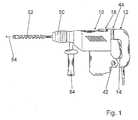
- Fig. 1shows an electric combi hammer for an optional use as a drill or chisel hammer with an electric motor not shown in detail in a housing 10 and a gear and a striking mechanism, via the one in a tool holder 50 clamped tool 52 is rotating and beating drivable. Contrary to an actuating direction 54 after the tool holder 50, a first handle 84 extending perpendicular to the actuating direction 84 is fastened to the housing 10.
- bow-shaped handle 12On a side facing away from the tool 52 of the housing 10, a second, perpendicular to the actuating direction 54 extending, bow-shaped handle 12 is arranged, which is remote from a tool axis first end via a hinge 42 with a transverse to the direction of actuation 54 pivot axis with the housing 10 is connected. At a second end of the handle 12 is connected via an insulating device 44 to the housing 10.
- the insulating device 44has a helical compression spring 56 for vibration isolation ( FIGS. 2 and 3 ), which is biased by a non-illustrated, the handle 12 and the housing 10 connecting tensioning and holding device.
- the helical compression spring 56acts with a first end on the handle 12 and is supported by a second end on the housing 10.
- the helical compression spring 56 and a spring chamber surrounding the helical compression spring 56are shielded to the outside by a rubber sleeve 58 and are protected from dirt.
- a pawl 14 designed as a switching rockeris disposed on the handle 12, which is connected in an articulated manner to the handle 12 via a joint 60 with a pivot axis extending transversely to the actuating direction 54.
- About the pawl 14can of a Operated an integrated in the handle 12 electrical on / off switch 16.
- the pawl 14is loaded on the insulating device 44 facing side of the joint 60 via a compression spring 62 in the direction of tool 52, in the direction of a starting position in which the Elektrokombihammer is turned off.
- a rotary knob 18with a rotation axis perpendicular to the actuation direction 54 for manual changeover from drill to chisel operation and vice versa is arranged.
- an eccentric 64is formed on the side facing the housing 10.
- An eccentric 64is formed by way of which the rotary knob 18 is in operative connection with a pivoting lever 32 of a latching device 20 extending parallel to the handle 12.
- the pivot lever 32is pivotally mounted via a hinge 68 with a pivot axis transverse to the actuating direction 54 on the housing 10.
- the latching device 20has a latching clip 24 with two connected via a joint 26, extending in the longitudinal direction of the Elektrokombihammers legs 28, 30 which are engageable with a the hinge 42 of the handle 12 facing the end of the pivot lever 32 for producing the latching function in operative connection ( FIGS. 2 and 3 ).
- the handle 12 facing side of the joint 26 of the locking clip 24are formed integrally formed at the ends of the legs 28, 30 on the inner sides by projections formed locking elements 36, 38.
- the locking clip 24is, in the handle 12 on the side 42 of the handle 12 facing side or is mounted directly above the hinge 42, and the legs 28, 30 are guided over two guides 74, 76 of the handle 12 in their pivoting movements.
- the eccentric 64points with its radially smaller diameter in the direction of handle 12.
- the pivot lever 32is with its pointing to the hinge 42 of the handle 12 end by the compression spring 70 between the legs 28, 30th pushed and blocks these in their pivotal movement on the pivot lever 32 side facing inward or on the handle 12 side facing the outside.
- the pawl 14is deflected on the insulating device 44 facing side opposite to the actuating direction 54 against the compression spring 62, ie the Elektrokombihammer is turned on.
- a bolt-shaped locking element 40is formed, which is pushed when turning the pawl 14 to turn on the electric combi hammer between the legs 28, 30.
- the legs 28, 30are thereby deflected elastically outwards.
- Has the bolt-shaped locking element 40the region of the locking elements 36, 38 of the legs 28, 30th traverses, grab the legs 28, 30 inward and engage behind the molded onto the pawl 14 bolt-shaped locking element 40 with its locking elements 36, 38.
- the pawl 14is locked.
- the legs 28, 30are made of an elastic plastic and form detent springs of the latching device 20.
- the legs 28, 30are designed in terms of elasticity and shape so that the locking element 40 is held securely despite the restoring force of the compression spring 62 during the chisel operation and of a Operator can be solved by pressing the pawl 14 on the locking clip 24 facing side of the joint 60 against the operating direction 54.
- the leg 72 of the pivot lever 32is pivoted by the eccentric 64 in the direction of the handle 12, whereby the pivot lever 32 pivots with its locking clip 24 facing the end towards the control unit 80, so that the blocking of the legs 28th , 30 lifted by the pivot lever 32 and the legs 28, 30 can pivot on the handle 12 side facing the outside ( 4 and 5 ).
- the integrally formed on the pawl 14 locking element 40can move freely through the locking elements 36, 38 of the locking clip 24. A latching of the pawl 14 and a friction between the locking element 40 of the pawl 14 and the locking elements 36, 38 of the locking clip 24 are avoided.
- a permanent magnet 78is also attached, which is engageable with a built-in electronic control unit 80 Hall sensor 82 in operative connection.
- the permanent magnet 78is located in the actuating direction 54 in front of the Hall sensor 82 (FIG. FIGS. 2 and 3 ). An effect of the permanent magnet 78 on the Hall sensor 82 is avoided, whereby the power of the electric combi hammer for the chisel operation is increased by a change in resistance via the electronic control unit 80.
- the permanent magnet 78is located above the Hall sensor 82 (FIG. 4 and 5 ).
- the permanent magnet 78acts on the Hall sensor 82, whereby the performance of the electric combi hammer for the drilling operation is reduced by a change in resistance via the electronic control unit 80.
- the embodiment in the 6 and 7has a locking device 22 with an electromagnetic actuator 46, via which a lifting rod 34 between two legs 28, 30 of a locking clip 24 is slidable to block them in their pivotal movement on a handle 12 facing side outward for a locking function.
- the electromagnetic actuator 46is electrically powered by an electronic Control unit 48, although via a permanent magnet 78 and a Hall sensor 82, which also serve to control the performance of the electric combi hammer for the chisel operation and the drilling operation via the electric control unit 48.
- the Hall sensor 82is integrated in the electronic control unit 48, and the permanent magnet is fixed to a pivot lever 66, which via a rotary knob 18 corresponding to the pivot lever 32 in the embodiment in the Fig. 1 to 5 is pressed.
- the permanent magnet 78is located in the operating direction 54 in front of the Hall sensor 82. An effect of the permanent magnet 78 on the Hall sensor 82 is avoided, thereby increasing the power of the electric combi hammer for the chisel by a change in resistance via the electronic control unit 48 and the lifting rod 34 is displaced by the electromagnetic actuator 46 between the two legs 28, 30 of the locking clip 24 in order to block them in their pivoting movement for the latching function.
- the permanent magnet 78acts on the Hall sensor 82, whereby the electronic control unit 48 reduces the power of the electric combi hammer for drilling operation by a change in resistance, and the lifting rod 34 by the electromagnetic Actuator 46 is displaced in the direction of the housing 10 and the blocking of the legs 28, 30 is lifted by the lifting rod 34, so that the legs 28, 30 can pivot on the side facing a pawl 14 side to the outside.
- One on the ratchet 14th Molded locking element 40can move freely through two locking elements 36, 38 of the locking clip 24. A latching of the pawl 14 and a friction between the locking element 40 of the pawl and the locking elements 36, 38 of the locking clip 24 are avoided.
- further control functions appearing appropriate to the person skilled in the artare also conceivable.
Landscapes
- Engineering & Computer Science (AREA)
- Mechanical Engineering (AREA)
- Percussive Tools And Related Accessories (AREA)
Abstract
Description
Translated fromGermanDie Erfindung geht aus von einem Elektrokombihammer nach dem Oberbegriff des Anspruchs 1.The invention relates to an electric combination hammer according to the preamble of claim 1.
Aus der
Die Schaltklinke ist im Meißelbetrieb über eine Rastvorrichtung in einer Raststellung einrastbar. Eine Raststellung im Bohrbetrieb wird jedoch vermieden. Die Rastvorrichtung besitzt ein erstes an der Schaltklinke angeordnetes Rastelement und ein zweites Rastelement, das an einem gelenkig am Gehäuse gelagerten Schwenkhebel angeordnet ist. Der Schwenkhebel ist mit einem an einen Schaltknebel zum manuellen Umstellen von Bohr- auf Meißelbetrieb und umgekehrt angeordneten Exzenternocken gekoppelt, an dessen Umfang der Schwenkhebel durch eine Druckfeder gedrückt ist. In einer den Bohrbetrieb einstellenden Schaltstellung des Schaltknebels liegt das an dem Schwenkhebel angeordnete Rastelement außerhalb einem Schaltweg des an der Schaltklinke angeordneten Rastelements. In einer den Meißelbetrieb einstellenden Schaltstellung des Schaltknebels ist der Schwenkhebel über den Exzenternocken mit seinem Rastelement in den Schaltweg des an der Schaltklinke angeordneten Rastelements verschoben. Das an der Schaltklinke befestigte Rastelement wird von einem eine Rastfeder bildenden Bauteil gebildet, das an seinem freien Ende einen Höcker aufweist, der.in das von einer Rastmulde gebildete Rastelement am Schwenkhebel im Meißelbetrieb einrasten kann.The pawl can be latched in chisel operation via a locking device in a detent position. However, a detent position during drilling operation is avoided. The latching device has a first locking element arranged on the pawl and a second latching element which is arranged on a pivoting lever mounted on the housing in an articulated manner. The pivot lever is coupled to a toggle switch for manually switching from drilling to chisel operation and vice versa arranged eccentric cam, on the circumference of the pivot lever is pressed by a compression spring. In a Bohrbetrieb adjusting switching position of the switch knob which is arranged on the pivot lever detent element is outside a switching path of the arranged on the pawl latching element. In a chiseling operation adjusting switching position of the switch knob of the pivot lever is moved via the eccentric cam with its locking element in the switching path of the arranged on the pawl latching element. The attached to the pawl locking element is formed by a detent spring forming member having a bump at its free end, which can engage .in the latching element formed by a detent recess on the pivot lever in the chisel mode.
Die Erfindung geht aus von einem Elektrokombihammer für einen wahlweisen Einsatz als Bohr- oder Meißelhammer mit einem Gehäuse und einem daran angeordneten Handgriff, in dem ein Ein-/Ausschalter mit einer Schaltklinke angeordnet ist, und mit einem Schaltelement zum manuellen Umstellen von Bohr- auf Meißelbetrieb und umgekehrt, und mit einer Rastvorrichtung, über die die Schaltklinke im Meißelbetrieb einrastbar ist und die im Bohrbetrieb eine Raststellung vermeidet.The invention relates to a Elektrokombihammer for an optional use as a drill or chisel hammer with a housing and a handle disposed thereon, in which an on / off switch is arranged with a pawl, and with a switching element for manually changing over on drilling Chisel operation and vice versa, and with a locking device over which the pawl in the chisel mode can be latched and avoids a detent position during drilling operation.
Es wird vorgeschlagen, daß die Rastvorrichtung eine Rastklammer mit zwei über ein Gelenk verbundenen Schenkeln aufweist, die mit einem das Gelenk in zumindest eine Schwenkrichtung blockierenden Blockierelement zur Herstellung der Rastfunktion in Wirkverbindung bringbar sind und zumindest ein Rastelement aufweisen, das mit einem mit der Schaltklinke in Wirkverbindung stehenden Rastelement in Wirkverbindung bringbar ist. Die Rastvorrichtung kann konstruktiv einfach ausgeführt, Reibung kann im Bohrbetrieb vermieden und die Rastklammer kann flexibel angeordnet werden. Insbesondere kann die Rastklammer bei einem beweglich gelagerten Handgriff konstruktiv einfach im Handgriff gelagert werden, wodurch eine Relativbewegung, hervorgerufen durch eine Bewegung des Handgriffs, zwischen den korrespondierenden Rastelementen und ein ungewünschtes Lösen der Rastverbindung vermieden werden kann.It is proposed that the latching device comprises a locking clip with two legs connected via a hinge, which are operatively connected to a blocking the hinge in at least one pivoting direction blocking element for producing the latching function and at least one latching element having a with the pawl in Active connection standing locking element can be brought into operative connection. The locking device can be structurally simple, friction can be avoided in drilling operation and the locking clip can be arranged flexibly. In particular, the locking clip can be stored in a movably mounted handle structurally simple in the handle, whereby a relative movement caused by a movement of the handle, between the corresponding locking elements and an unwanted release of the locking connection can be avoided.
Das Blockierelement wird vorteilhaft am Gehäuse gelagert und kann dadurch vorteilhaft über das Schaltelement entsprechend in seiner Bewegung gesteuert werden. Ist der Handgriff an einem ersten Ende über ein Gelenk und einem zweiten Ende über eine Isoliervorrichtung mit dem Gehäuse verbunden, und ist die Rastklammer auf der dem Gelenk zugewandten Seite des Handgriffs gelagert, können zwischen dem am Gehäuse gelagerten Blockierelement und der Rastklammer eine Relativbewegung, eine dadurch bedingte Reibung und ein Verschleiß klein gehalten werden.The blocking element is advantageously mounted on the housing and can be advantageously controlled by the switching element accordingly in its movement. If the handle is connected at a first end via a hinge and a second end via an insulating device to the housing, and the latching clip is mounted on the side facing the hinge of the handle, between the housing mounted on the blocking element and the locking clip a relative movement, a consequent friction and wear are kept small.
Das Blockierelement kann über das Schaltelement rein mechanisch ansteuerbar ausgeführt sein, beispielsweise indem das Blockierelement über einen Schalthebel mit dem Schaltelement in Wirkverbindung steht, oder kann über das Schaltelement elektrisch ansteuerbar ausgeführt sein. Mit einer elektrischen Ansteuerung kann eine mechanische Verbindung zwischen dem Schaltelement und dem Blockierelement vermieden und es können Bauteile, Bauraum, Gewicht, Montageaufwand und Kosten eingespart werden. Ferner können konstruktive Freiheitsgrade geschaffen werden. Das Blockierelement kann dabei über einen Elektromotor oder besonders vorteilhaft über einen elektromagnetischen Aktuator betätigbar ausgeführt werden. Ein entsprechender elektromagnetischer Aktuator kann konstruktiv einfach und kostengünstig ausgeführt werden.The blocking element can be embodied purely mechanically controllable via the switching element, for example by the blocking element being in operative connection with the switching element via a switching lever, or it can be designed to be electrically controllable via the switching element. With an electrical control, a mechanical connection between the switching element and the blocking element can be avoided and components, space, weight, assembly costs and costs can be saved. Furthermore, constructive degrees of freedom can be created. The blocking element can be made operable via an electric motor or particularly advantageously via an electromagnetic actuator. A corresponding electromagnetic actuator can be structurally simple and inexpensive.
Um Bauteile, Bauraum, Gewicht und Montageaufwand einzusparen, ist vorteilhaft eine Steuereinheit zur Ansteuerung des Blokkierelements zumindest teilweise, vorzugsweise vollständig einstückig mit einer Steuereinheit zur Steuerung des Wechsels vom Bohr- auf den Meißelbetrieb und umgekehrt ausgeführt. Ferner können Bauteile, Bauraum und Gewicht eingespart werden, indem zumindest ein Rastelement einstückig mit einer Rastfeder und/oder zumindest ein Schenkel der Rastklammer einstückig mit einem Rastelement ausgebildet ist.In order to save components, space, weight and assembly costs, a control unit for controlling the blocking element is advantageously at least partially, preferably completely in one piece with a control unit for controlling the change from drilling to chiseling and vice versa. Further components, space and weight can be saved by at least one locking element is integrally formed with a detent spring and / or at least one leg of the locking clip integral with a locking element.
Weitere Vorteile ergeben sich aus der folgenden Zeichnungsbeschreibung. In der Zeichnung sind Ausführungsbeispiele der Erfindung dargestellt. Die Zeichnung, die Beschreibung und die Ansprüche enthalten zahlreiche Merkmale in Kombination. Der Fachmann wird die Merkmale zweckmäßigerweise auch einzeln betrachten und zu sinnvollen weiteren Kombinationen zusammenfassen.Further advantages emerge from the following description of the drawing. In the drawings, embodiments of the invention are shown. The drawing, the description and The claims contain numerous features in combination. The person skilled in the art will expediently also consider the features individually and combine them into meaningful further combinations.
Es zeigen:
- Fig. 1
- einen schematisch dargestellten Elektrokombihammer,
- Fig. 2
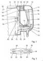
- einen Längsschnitt durch einen Handgriff aus
Fig. 1 mit einer eingerasteten Schaltklinke in einem Meißelbetrieb, - Fig. 3
- eine vergrößerte Darstellung einer Rastklammer aus
Fig. 2 von oben, - Fig. 4
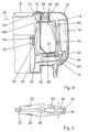
- den Handgriff aus
Fig. 2 bei einem Bohrbetrieb, - Fig. 5
- eine vergrößerte Darstellung der Rastklammer aus
Fig. 4 von oben, - Fig. 6
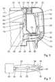
- eine Variante zu
Fig. 2 mit einem elektromagnetischen Aktuator und - Fig. 7
- eine vergrößerte Darstellung einer Rast klammer aus
Fig. 6 von oben.
- Fig. 1
- a schematically illustrated electric combination hammer,
- Fig. 2
- a longitudinal section through a handle
Fig. 1 with a latched pawl in a chisel operation, - Fig. 3
- an enlarged view of a locking clip
Fig. 2 from above, - Fig. 4
- the handle off
Fig. 2 in a drilling operation, - Fig. 5
- an enlarged view of the locking clip
Fig. 4 from above, - Fig. 6
- a variant too
Fig. 2 with an electromagnetic actuator and - Fig. 7
- an enlarged view of a locking bracket
Fig. 6 from above.
Auf einer dem Werkzeug 52 abgewandten Seite des Gehäuses 10 ist ein zweiter, sich senkrecht zur Betätigungsrichtung 54 erstreckender, bügelförmiger Handgriff 12 angeordnet, der an einem von einer Werkzeugachse abgewandten ersten Ende über ein Gelenk 42 mit einer quer zur Betätigungsrichtung 54 verlaufenden Schwenkachse mit dem Gehäuse 10 verbunden ist. An einem zweiten Ende ist der Handgriff 12 über eine Isoliervorrichtung 44 mit dem Gehäuse 10 verbunden.On a side facing away from the
Die Isoliervorrichtung 44 besitzt eine Schraubendruckfeder 56 zur Schwingungsisolierung (
Auf einer dem Werkzeug 52 zugewandten Seite ist am Handgriff 12 eine als Schaltwippe ausgebildete Schaltklinke 14 angeordnet, die über ein Gelenk 60 mit einer quer zur Betätigungsrichtung 54 verlaufenden Schwenkachse mit dem Handgriff 12 gelenkig verbunden ist. Über die Schaltklinke 14 kann von einem Bediener ein im Handgriff 12 integrierter elektrischer Ein-/ Ausschalter 16 betätigt werden. Die Schaltklinke 14 wird auf der der Isoliervorrichtung 44 zugewandten Seite des Gelenks 60 über eine Druckfeder 62 in Richtung Werkzeug 52 belastet, und zwar in Richtung einer Ausgangsstellung, in der der Elektrokombihammer ausgeschaltet ist.On a side facing the
An einer Deckseite des Elektrokombihammers ist ein Drehknopf 18 mit einer Drehachse senkrecht zur Betätigungsrichtung 54 zum manuellen Umstellen von Bohr- auf Meißelbetrieb und umgekehrt angeordnet. Am Drehknopf 18 ist an der dem Gehäuse 10 zugewandten.Seite ein Exzenter 64 angeformt, über den der Drehknopf 18 mit einem parallel zum Handgriff 12 verlaufenden Schwenkhebel 32 einer Rastvorrichtung 20 in Wirkverbindung steht. Der Schwenkhebel 32 ist über ein Gelenk 68 mit einer Schwenkachse quer zur Betätigungsrichtung 54 am Gehäuse 10 schwenkbar gelagert. Auf der dem Drehknopf 18 abgewandten Seite des Gelenks 68 ist der Schwenkhebel 32 in Richtung Handgriff 12 über eine Druckfeder 70 belastet und wird über die Druckfeder 70 mit dem dem Drehknopf 18 zugewandten Ende mit einer Stirnseite eines sich in Betätigungsrichtung 54 erstreckenden, angeformten Schenkels 72 gegen den Exzenter 64 gedrückt.On a cover side of the electric combi hammer, a
Erfindungsgemäß besitzt die Rastvorrichtung 20 eine Rastklammer 24 mit zwei über ein Gelenk 26 verbundenen, sich in Längsrichtung des Elektrokombihammers erstreckenden Schenkeln 28, 30, die mit einem dem Gelenk 42 des Handgriffs 12 zugewandten Ende des Schwenkhebels 32 zur Herstellung der Rastfunktion in Wirkverbindung bringbar sind (
Die Rastklammer 24 ist,im Handgriff 12 auf der dem Gelenk 42 des Handgriffs 12 zugewandten Seite bzw. ist unmittelbar über dem Gelenk 42 gelagert, und die Schenkel 28, 30 sind über zwei Führungen 74, 76 des Handgriffs 12 in ihren Schwenkbewegungen geführt.The locking
Die Schaltklinke 14 ist auf der der Isoliervorrichtung 44 zugewandten Seite entgegen der Betätigungsrichtung 54 gegen die Druckfeder 62 ausgelenkt, d.h. der Elektrokombihammer ist eingeschaltet. An einem der Isoliervorrichtung 44 abgewandten Ende der Schaltklinke 14 ist ein bolzenförmiges Rastelement 40 angeformt, das beim Auslenken der Schaltklinke 14 zum Einschalten des Elektrokombihammers zwischen die Schenkel 28, 30 geschoben wird. Die Schenkel 28, 30 werden dabei elastisch nach außen ausgelenkt. Hat das bolzenförmige Rastelement 40 den Bereich der Rastelemente 36, 38 der Schenkel 28, 30 durchquert, schnappen die Schenkel 28, 30 nach innen und hintergreifen das an die Schaltklinke 14 angeformte bolzenförmige Rastelement 40 mit ihren Rastelementen 36, 38. Die Schaltklinke 14 ist arretiert.The
Die Schenkel 28, 30 sind aus einem elastischen Kunststoff hergestellt und bilden Rastfedern der Rastvorrichtung 20. Die Schenkel 28, 30 sind bezüglich Elastizität und Formgebung so ausgelegt, daß das Rastelement 40 trotz der Rückstellkraft der Druckfeder 62 während des Meißelbetriebs sicher gehalten wird und von einem Bediener durch Drücken der Schaltklinke 14 auf der der Rastklammer 24 zugewandten Seite des Gelenks 60 entgegen der Betätigungsrichtung 54 gelöst werden kann.The
Ist der Drehknopf 18 auf Bohrbetrieb eingestellt, wird der Schenkel 72 des Schwenkhebels 32 durch den Exzenter 64 in Richtung des Handgriffs 12 geschwenkt, wodurch der Schwenkhebel 32 mit seinem der Rastklammer 24 zugewandten Ende in Richtung Steuereinheit 80 schwenkt, so daß die Blockierung der Schenkel 28, 30 durch den Schwenkhebel 32 aufgehoben und die Schenkel 28, 30 auf der dem Handgriff 12 zugewandten Seite nach außen schwenken können (
Am Schwenkhebel 32 ist zudem ein Permanentmagnet 78 befestigt, der mit einem in einer elektronischen Steuereinheit 80 integrierten Hallsensor 82 in Wirkverbindung bringbar ist.On the
Ist der Drehknopf 18 auf Meißelbetrieb eingestellt, liegt der Permanentmagnet 78 in Betätigungsrichtung 54 vor dem Hallsensor 82 (
Ist der Drehknopf 18 auf Bohrbetrieb eingestellt, liegt der Permanentmagnet 78 über dem Hallsensor 82 (
In den
Das Ausführungsbeispiel in den
Ist der Drehknopf 18 auf Meißelbetrieb eingestellt, liegt der Permanentmagnet 78 in Betätigungsrichtung 54 vor dem Hallsensor 82. Eine Wirkung des Permanentmagneten 78 auf den Hallsensor 82 wird vermieden, wodurch über die elektronische Steuereinheit 48 die Leistung des Elektrokombihammers für den Meißelbetrieb durch eine Widerstandsänderung erhöht und die Hubstange 34 durch den elektromagnetischen Aktuator 46 zwischen die zwei Schenkel 28, 30 der Rastklammer 24 verschoben wird, um diese in ihrer Schwenkbewegung für die Rastfunktion zu blockieren.If the
Ist der Drehknopf 18 auf Bohrbetrieb eingestellt, liegt der Permanentmagnet 78 über dem Hallsensor 82. Der Permanentmagnet 78 wirkt auf den Hallsensor 82, wodurch die elektronische Steuereinheit 48 die Leistung des Elektrokombihammers für den Bohrbetrieb durch eine Widerstandsänderung reduziert, und die Hubstange 34 durch den elektromagnetischen Aktuator 46 in Richtung Gehäuse 10 verschoben und die Blockierung der Schenkel 28, 30 durch die Hubstange 34 aufgehoben ist, so daß die Schenkel 28, 30 auf der einer Schaltklinke 14 zugewandten Seite nach außen schwenken können. Ein an der Schaltklinke 14 angeformtes Rastelement 40 kann sich frei durch zwei Rastelemente 36, 38 der Rastklammer 24 bewegen. Ein Einrasten der Schaltklinke 14 und eine Reibung zwischen dem Rastelement 40 der Schaltklinke und den Rastelementen 36, 38 der Rastklammer 24 werden vermieden. Neben den beschriebenen Steuerfunktionen des Permanentmagneten 78 und des Hallsensors 82 sind auch weitere, dem Fachmann als sinnvoll erscheinende Steuerfunktionen denkbar.The
- 1010
- Gehäusecasing
- 1212
- Handgriffhandle
- 1414
- Schaltklinkeratchet
- 1616
- Ein-/AusschalterOn / off switch
- 1818
- Schaltelementswitching element
- 2020
- Rastvorrichtunglocking device
- 2222
- Rastvorrichtunglocking device
- 2424
- Rastklammerlocking clip
- 2626
- Gelenkjoint
- 2828
- Schenkelleg
- 3030
- Schenkelleg
- 3232
- Bauteilcomponent
- 3434
- Bauteilcomponent
- 3636
- Rastelementlocking element
- 3838
- Rastelementlocking element
- 4040
- Rastelementlocking element
- 4242
- Gelenkjoint
- 4444
- Isoliervorrichtunginsulating
- 4646
- Aktuatoractuator
- 4848
- Steuereinheitcontrol unit
- 5050
- Werkzeughalterungtool holder
- 5252
- WerkzeugTool
- 5454
- Betätigungsrichtungoperating direction
- 5656
- SchraubendruckfederHelical compression spring
- 5858
- Gummimanschetterubber sleeve
- 6060
- Gelenkjoint
- 6262
- Druckfedercompression spring
- 6464
- Exzentereccentric
- 6666
- Schwenkhebelpivoting lever
- 6868
- Gelenkjoint
- 7070
- Druckfedercompression spring
- 7272
- Schenkelleg
- 7474
- Führungguide
- 7676
- Führungguide
- 7878
- Permanentmagnetpermanent magnet
- 8080
- Steuereinheitcontrol unit
- 8282
- HallsensorHall sensor
- 8484
- Handgriffhandle
Claims (8)
- Electric combination hammer drill for optional use as a hammer drill or rotary demolition hammer, comprising a housing (10) and a handle (12) which is arranged thereon and in which an on/off switch (16) having a pawl (14) is arranged, and comprising a switching element (18) for manually changing over from drilling to chiselling operation and vice versa, and comprising a latching device (20, 22), via which the pawl (14) can be latched in place during chiselling operation and which avoids a latching position during drilling operation,characterized in that the latching device (20, 22) has a latching clip (24) having two legs (28, 30) which are connected via a joint (26) and which can be brought into operative connection with a locking element (32, 34), locking the joint (26) in at least one pivoting direction for producing the latching function and have at least one latching element (36, 38) which can be brought into operative connection with a latching element (40) which is in operative connection with the pawl (14).
- Electric combination hammer drill according to Claim 1,characterized in that the handle (12) is movably mounted and the latching clip (24) is mounted in the handle (12).
- Electric combination hammer drill according to Claim 2,characterized in that the handle (12) is connected to the housing (10) at a first end via a joint (42) and at a second end via an insulating device (44), and the latching clip (24) is mounted on that side of the handle (12) which faces the joint (42).
- Electric combination hammer drill according to one of the preceding claims,characterized in that the locking element (34) can be activated electrically.
- Electric combination hammer drill according to Claim 4,characterized in that the locking element (34) can be actuated via an electromagnetic actuator (46).
- Electric combination hammer drill according to Claim 4 or 5,characterized in that a control unit (48) for activating the locking element (34) is formed at least partly in one piece with a control unit (48) for controlling the change from drilling operation to chiselling operation and vice versa.
- Electric combination hammer drill according to one of the preceding claims,characterized in that at least one latching element (36, 38) is formed in one piece with a latching spring.
- Electric combination hammer drill according to one of the preceding claims,characterized in that at least one leg (28, 30) of the latching clip (24) is formed in one piece with a latching element (36, 38).
Applications Claiming Priority (3)
| Application Number | Priority Date | Filing Date | Title |
|---|---|---|---|
| DE10034768 | 2000-07-18 | ||
| DE10034768ADE10034768A1 (en) | 2000-07-18 | 2000-07-18 | Combination electric hand tool operating as hammer drill or electric chisel, has pivoted jaw catch mechanism with blocking component in handle |
| PCT/DE2001/001962WO2002006015A1 (en) | 2000-07-18 | 2001-05-23 | Electric combination hammer-drill |
Publications (2)
| Publication Number | Publication Date |
|---|---|
| EP1303383A1 EP1303383A1 (en) | 2003-04-23 |
| EP1303383B1true EP1303383B1 (en) | 2008-04-30 |
Family
ID=7649235
Family Applications (1)
| Application Number | Title | Priority Date | Filing Date |
|---|---|---|---|
| EP01944950AExpired - LifetimeEP1303383B1 (en) | 2000-07-18 | 2001-05-23 | Electric combination hammer-drill |
Country Status (5)
| Country | Link |
|---|---|
| US (1) | US6766868B2 (en) |
| EP (1) | EP1303383B1 (en) |
| JP (1) | JP4873595B2 (en) |
| DE (2) | DE10034768A1 (en) |
| WO (1) | WO2002006015A1 (en) |
Cited By (2)
| Publication number | Priority date | Publication date | Assignee | Title |
|---|---|---|---|---|
| WO2013030380A1 (en)* | 2011-09-02 | 2013-03-07 | Robert Bosch Gmbh | Handle device |
| DE102020001076A1 (en) | 2020-02-19 | 2021-08-19 | Metabowerke Gmbh | Hand machine tool |
Families Citing this family (87)
| Publication number | Priority date | Publication date | Assignee | Title |
|---|---|---|---|---|
| DE10130088C2 (en)* | 2001-06-21 | 2003-10-16 | Hilti Ag | Striking electric hand tool device with active vibration damping |
| DE10136015A1 (en)* | 2001-07-24 | 2003-02-13 | Bosch Gmbh Robert | Hand-held machine tool has vibration-dampened hand grip of two legs with levers hinged top hand grip legs and machine housing |
| DE10240361A1 (en)* | 2002-09-02 | 2004-03-11 | Hilti Ag | Rotating and striking electric hand machine tool |
| DE10316844A1 (en)* | 2003-04-11 | 2004-11-04 | Hilti Ag | Control of an electric hand machine tool |
| JP4243135B2 (en)* | 2003-05-09 | 2009-03-25 | 株式会社マキタ | Electric hammer drill |
| GB2402098B (en)* | 2003-05-21 | 2007-10-17 | Black & Decker Inc | Vibration reduction apparatus for power tool and power tool incorporating such apparatus |
| EP2281665B1 (en)* | 2003-09-10 | 2017-04-12 | Makita Corporation | Vibration isolating handle |
| GB2407791A (en)* | 2003-11-04 | 2005-05-11 | Black & Decker Inc | Vibration reduction apparatus for a power tool |
| GB2407790A (en)* | 2003-11-04 | 2005-05-11 | Black & Decker Inc | Vibration reduction apparatus for a power tool |
| GB2407789A (en)* | 2003-11-04 | 2005-05-11 | Black & Decker Inc | Vibration reduction apparatus for a power tool |
| DE10355103B4 (en)* | 2003-11-24 | 2010-03-18 | Itw-Befestigungssysteme Gmbh | Vibration-damped handle for a hand-held power tool |
| DE102004012433A1 (en) | 2004-03-13 | 2005-09-29 | Robert Bosch Gmbh | Hand tool |
| GB2414702A (en) | 2004-06-04 | 2005-12-07 | Black & Decker Inc | Vibration Reduction Apparatus for Power Tool |
| JP4509662B2 (en)* | 2004-06-16 | 2010-07-21 | 株式会社マキタ | Electric impact tool |
| JP4647957B2 (en)* | 2004-08-27 | 2011-03-09 | 株式会社マキタ | Work tools |
| ES2295786T3 (en)* | 2004-09-22 | 2008-04-16 | Black & Decker Inc. | PUSH BUTTON WITH LOCK CAPACITY FOR DRILLING HAMMER. |
| DE102004051465A1 (en)* | 2004-10-22 | 2006-04-27 | Robert Bosch Gmbh | Hand tool with vibration damped pistol handle |
| JP4573637B2 (en)* | 2004-12-02 | 2010-11-04 | 株式会社マキタ | Reciprocating work tool |
| USD527601S1 (en) | 2005-02-10 | 2006-09-05 | Black & Decker Inc. | Hammer |
| USD540642S1 (en) | 2005-02-10 | 2007-04-17 | Black & Decker Inc. | Hammer |
| USD524626S1 (en) | 2005-02-10 | 2006-07-11 | Black & Decker Inc. | Hammer |
| DE102005007547B4 (en)* | 2005-02-18 | 2024-11-07 | Robert Bosch Gmbh | hand tool machine |
| GB0503558D0 (en)* | 2005-02-22 | 2005-03-30 | Black & Decker Inc | Actuation apparatus for power tool |
| GB0503784D0 (en)* | 2005-02-24 | 2005-03-30 | Black & Decker Inc | Hammer drill |
| DE102005000161A1 (en)* | 2005-11-21 | 2007-05-24 | Hilti Ag | Hand tool with foamed wiring |
| DE102006021307A1 (en)* | 2006-05-08 | 2007-11-15 | Robert Bosch Gmbh | Hand tool with a vibration-damped handle |
| DE102006000287A1 (en) | 2006-06-09 | 2007-12-13 | Hilti Ag | Hand tool with vibration reducing device |
| DE102006027774A1 (en)* | 2006-06-16 | 2007-12-20 | Robert Bosch Gmbh | Hand tool |
| JP4626574B2 (en)* | 2006-06-16 | 2011-02-09 | 日立工機株式会社 | Electric tool |
| DE102006029630A1 (en)* | 2006-06-28 | 2008-01-03 | Robert Bosch Gmbh | Hand tool |
| DE102006040647A1 (en)* | 2006-08-30 | 2008-03-13 | Robert Bosch Gmbh | Hand tool |
| US20080092396A1 (en)* | 2006-10-19 | 2008-04-24 | Kuang-Pin Wang | Bow saw structure |
| DE102006051924A1 (en)* | 2006-11-03 | 2008-05-15 | Robert Bosch Gmbh | Hand tool with a vibration-damped, provided with a switch handle |
| DE102006052807A1 (en)* | 2006-11-09 | 2008-05-15 | Robert Bosch Gmbh | Hand tool with a vibration-damped strap handle |
| DE102007001591A1 (en)* | 2007-01-10 | 2008-07-17 | Aeg Electric Tools Gmbh | Portable, hand-held machine tool |
| DE102007000093A1 (en)* | 2007-02-15 | 2008-08-21 | Hilti Ag | Hand tool |
| JP2008264935A (en)* | 2007-04-20 | 2008-11-06 | Makita Corp | Handle of hand tool |
| DE102007000362A1 (en) | 2007-07-02 | 2009-01-08 | Hilti Aktiengesellschaft | Vibrating hand tool with a lock switch of the engine switch |
| DE102007030703A1 (en)* | 2007-07-02 | 2009-01-08 | Robert Bosch Gmbh | Elastic connection between housing parts of motor-driven machine tools |
| DE102007000470A1 (en)* | 2007-08-29 | 2009-03-05 | Hilti Aktiengesellschaft | Vibrating hand tool with a lock switch of the engine switch |
| DE102007043917A1 (en)* | 2007-09-14 | 2009-04-02 | Robert Bosch Gmbh | Electric hand machine tool i.e. drill hammer, has hammer mechanism and electric motor arranged at intermediate flange and connected with each other, and main handle arranged at tool by vibration-decoupling device |
| DE102007055843A1 (en)* | 2007-12-17 | 2009-06-25 | Hilti Aktiengesellschaft | Hand tool with vibration compensator |
| GB0804963D0 (en)* | 2008-03-18 | 2008-04-16 | Black & Decker Inc | Hammer |
| GB0804964D0 (en)* | 2008-03-18 | 2008-04-16 | Black & Decker Inc | Hammer |
| JP5180697B2 (en)* | 2008-06-19 | 2013-04-10 | 株式会社マキタ | Hand-held work tool |
| DE102008041511A1 (en) | 2008-08-25 | 2010-03-04 | Robert Bosch Gmbh | Device main switch for electric machine tools, in particular electric hand tools, and an electric hand tool |
| JP5405864B2 (en)* | 2009-03-23 | 2014-02-05 | 株式会社マキタ | Impact tool |
| JP5502352B2 (en)* | 2009-03-23 | 2014-05-28 | 株式会社マキタ | Electric tool |
| DE102009002589A1 (en)* | 2009-04-23 | 2010-10-28 | Hilti Aktiengesellschaft | Hand tool |
| US8418778B2 (en) | 2010-01-07 | 2013-04-16 | Black & Decker Inc. | Power screwdriver having rotary input control |
| DE102010038750A1 (en)* | 2010-08-02 | 2012-02-02 | Robert Bosch Gmbh | Electric power tool with lockable rocker switch |
| DE102010038753A1 (en)* | 2010-08-02 | 2012-02-02 | Robert Bosch Gmbh | Anti-vibration handle with train-loaded switch connection |
| US20120048580A1 (en)* | 2010-09-01 | 2012-03-01 | Hilti Aktiengesellschaft | Power tool |
| DE102010063962A1 (en)* | 2010-12-22 | 2012-06-28 | Robert Bosch Gmbh | Lockable electrical switch |
| GB201112825D0 (en)* | 2011-07-26 | 2011-09-07 | Black & Decker Inc | A hammer drill |
| DE202011108753U1 (en)* | 2011-12-06 | 2012-01-24 | Gardena Manufacturing Gmbh | Hand-held device with a control lever |
| DE102012208855A1 (en)* | 2012-05-25 | 2013-11-28 | Robert Bosch Gmbh | Hand tool |
| DE102012208913A1 (en)* | 2012-05-25 | 2013-11-28 | Robert Bosch Gmbh | Percussion unit |
| DE102012209868A1 (en)* | 2012-06-13 | 2013-12-19 | Robert Bosch Gmbh | gearbox |
| US8966773B2 (en)* | 2012-07-06 | 2015-03-03 | Techtronic Power Tools Technology Limited | Power tool including an anti-vibration handle |
| JP6096593B2 (en)* | 2013-05-29 | 2017-03-15 | 株式会社マキタ | Reciprocating work tool |
| JP6334144B2 (en) | 2013-11-26 | 2018-05-30 | 株式会社マキタ | Reciprocating work tool |
| USD765485S1 (en)* | 2014-01-21 | 2016-09-06 | Robert Bosch Gmbh | Hammer drill |
| EP2898994A1 (en) | 2014-01-23 | 2015-07-29 | Black & Decker Inc. | Power tool with rear handle |
| EP2898991B1 (en) | 2014-01-23 | 2018-12-26 | Black & Decker Inc. | Rear handle |
| EP2898992B1 (en) | 2014-01-23 | 2016-05-04 | Black & Decker Inc. | Power tool with rear handle, method of manufacturing a part of a handle assembly for a power tool and method of disassembling a part of a handle assembly for a power tool |
| EP2898993B1 (en)* | 2014-01-23 | 2019-01-30 | Black & Decker Inc. | Power tool |
| JP6620434B2 (en)* | 2015-06-12 | 2019-12-18 | マックス株式会社 | Impact tool |
| EP3117963A1 (en)* | 2015-07-17 | 2017-01-18 | HILTI Aktiengesellschaft | Manual machine tool |
| DE102015226440A1 (en)* | 2015-12-22 | 2017-06-22 | Robert Bosch Gmbh | Hand machine tool device |
| KR102251270B1 (en) | 2016-01-05 | 2021-05-11 | 밀워키 일렉트릭 툴 코포레이션 | Vibration reduction system and method for power tools |
| EP3381620B1 (en)* | 2017-03-31 | 2019-08-28 | Andreas Stihl AG & Co. KG | Manually operated work device |
| EP3581337A1 (en)* | 2018-06-11 | 2019-12-18 | HILTI Aktiengesellschaft | Handheld machine tool |
| EP3593951A1 (en)* | 2018-07-11 | 2020-01-15 | Hilti Aktiengesellschaft | Handheld machine tool |
| US11400577B2 (en)* | 2019-06-11 | 2022-08-02 | Makita Corporation | Impact tool |
| MX2021014887A (en) | 2019-06-12 | 2022-01-18 | Milwaukee Electric Tool Corp | Rotary power tool. |
| USD941650S1 (en)* | 2019-09-27 | 2022-01-25 | Zhejiang Prulde Electric Appliance Co., Ltd. | Lithium-ion battery hammer drill |
| JP7601555B2 (en)* | 2020-02-03 | 2024-12-17 | 株式会社マキタ | Hammer Drill |
| JP7624319B2 (en)* | 2021-02-04 | 2025-01-30 | 株式会社マキタ | Impact tools |
| JP7585085B2 (en)* | 2021-02-22 | 2024-11-18 | 株式会社マキタ | Impact tools |
| JP7704580B2 (en)* | 2021-06-10 | 2025-07-08 | 株式会社マキタ | Rotary impact tool |
| DE102021206546A1 (en) | 2021-06-24 | 2022-12-29 | Zf Friedrichshafen Ag | Method and control device for operating a drive train |
| DE102021206547B4 (en) | 2021-06-24 | 2024-12-24 | Zf Friedrichshafen Ag | Method and control device for operating a drive train |
| EP4257293A1 (en)* | 2022-04-08 | 2023-10-11 | Milwaukee Electric Tool Corporation | Rotary hammer |
| JP2024035285A (en)* | 2022-09-02 | 2024-03-14 | 株式会社マキタ | hammer drill |
| EP4400263A1 (en)* | 2023-01-11 | 2024-07-17 | Hilti Aktiengesellschaft | Electric hand tool |
| US12397404B2 (en) | 2023-05-30 | 2025-08-26 | Milwaukee Electric Tool Corporation | Operating mode detection system for rotary hammer |
Family Cites Families (13)
| Publication number | Priority date | Publication date | Assignee | Title |
|---|---|---|---|---|
| US1356556A (en)* | 1919-01-27 | 1920-10-26 | Walter S Payne | Electric power-hammer and drilling-machine combined |
| US4204580A (en)* | 1978-08-03 | 1980-05-27 | The Singer Company | Forward biased switch for a reversible hammer drill |
| US4342931A (en)* | 1981-01-29 | 1982-08-03 | Black & Decker Inc. | Brush-shifting and trigger-switch arrangements for a portable tool |
| US4348603A (en)* | 1981-01-29 | 1982-09-07 | Black & Decker Inc. | Printed-circuit board and trigger-switch arrangement for a portable electric tool |
| GB2112479B (en)* | 1981-11-13 | 1985-05-01 | Black & Decker Inc | Latching arrangement |
| DE3627869A1 (en)* | 1986-08-16 | 1988-02-18 | Bosch Gmbh Robert | DRIVE SHUTDOWN |
| DE3841515A1 (en)* | 1988-12-09 | 1990-06-13 | Hilti Ag | HAND TOOL WITH MANUAL GEARBOX |
| US5697456A (en)* | 1995-04-10 | 1997-12-16 | Milwaukee Electric Tool Corp. | Power tool with vibration isolated handle |
| DE19720947B4 (en)* | 1996-06-15 | 2005-07-28 | Robert Bosch Gmbh | Electric combination hammer |
| DE19631517A1 (en)* | 1996-08-03 | 1998-02-05 | Wacker Werke Kg | Variable-speed, hand-held power tool driven by an electric motor that can be connected to single-phase alternating current |
| JPH11277462A (en)* | 1998-03-27 | 1999-10-12 | Makita Corp | Switch mechanism for power tool |
| JP2000033507A (en)* | 1998-07-16 | 2000-02-02 | Ryobi Ltd | Striking force adjusting mechanism of hammer drill |
| DE19937767B4 (en) | 1999-08-10 | 2004-09-09 | Hilti Ag | Hand-held electric combi hammer |
- 2000
- 2000-07-18DEDE10034768Apatent/DE10034768A1/ennot_activeCeased
- 2001
- 2001-05-23USUS10/088,220patent/US6766868B2/ennot_activeExpired - Lifetime
- 2001-05-23EPEP01944950Apatent/EP1303383B1/ennot_activeExpired - Lifetime
- 2001-05-23WOPCT/DE2001/001962patent/WO2002006015A1/enactiveIP Right Grant
- 2001-05-23JPJP2002511936Apatent/JP4873595B2/ennot_activeExpired - Fee Related
- 2001-05-23DEDE50113916Tpatent/DE50113916D1/ennot_activeExpired - Lifetime
Cited By (5)
| Publication number | Priority date | Publication date | Assignee | Title |
|---|---|---|---|---|
| WO2013030380A1 (en)* | 2011-09-02 | 2013-03-07 | Robert Bosch Gmbh | Handle device |
| WO2013030382A1 (en)* | 2011-09-02 | 2013-03-07 | Robert Bosch Gmbh | Handle device |
| WO2013030377A1 (en)* | 2011-09-02 | 2013-03-07 | Robert Bosch Gmbh | Handle device |
| WO2013030381A1 (en)* | 2011-09-02 | 2013-03-07 | Robert Bosch Gmbh | Handle device |
| DE102020001076A1 (en) | 2020-02-19 | 2021-08-19 | Metabowerke Gmbh | Hand machine tool |
Also Published As
| Publication number | Publication date |
|---|---|
| JP4873595B2 (en) | 2012-02-08 |
| JP2004504169A (en) | 2004-02-12 |
| DE50113916D1 (en) | 2008-06-12 |
| US6766868B2 (en) | 2004-07-27 |
| US20030037937A1 (en) | 2003-02-27 |
| EP1303383A1 (en) | 2003-04-23 |
| DE10034768A1 (en) | 2002-02-07 |
| WO2002006015A1 (en) | 2002-01-24 |
Similar Documents
| Publication | Publication Date | Title |
|---|---|---|
| EP1303383B1 (en) | Electric combination hammer-drill | |
| EP1944134B1 (en) | Portable manually-operated machine tool | |
| EP1932625B1 (en) | Electric hand tool device | |
| EP2129496B1 (en) | Hand machine tool | |
| WO2006120092A1 (en) | Electric machine tool | |
| DE102010038750A1 (en) | Electric power tool with lockable rocker switch | |
| DE102004057686A1 (en) | switching device | |
| EP2030738A2 (en) | Vibrating hand machine tool with a locking switch for the motor switch | |
| DE102010038753A1 (en) | Anti-vibration handle with train-loaded switch connection | |
| EP2656362B1 (en) | Lockable electrical switch | |
| EP1259357B1 (en) | Machine tool | |
| WO2010023013A1 (en) | Device main switch for electric machine tools, particularly electric hand tools, and electric hand tool | |
| DE102008054786A1 (en) | rotary switch | |
| DE10152963A1 (en) | electric machine | |
| DE19720947B4 (en) | Electric combination hammer | |
| EP3802000B1 (en) | Handheld machine tool | |
| DE102022102194A1 (en) | POWER TOOL WITH A HAMMER MECHANISM | |
| DE102010064371B4 (en) | Hand tool clamping device with switching element | |
| EP2027972B1 (en) | Hand tool with reciprocating drive | |
| DE10153574A1 (en) | electric machine | |
| EP3593951A1 (en) | Handheld machine tool | |
| DE10230586B4 (en) | Motor vehicle door lock | |
| DE102004019778B4 (en) | switching piece | |
| WO2008077660A1 (en) | Machine tool switching device | |
| EP1616472B1 (en) | Mobile soil working device |
Legal Events
| Date | Code | Title | Description |
|---|---|---|---|
| PUAI | Public reference made under article 153(3) epc to a published international application that has entered the european phase | Free format text:ORIGINAL CODE: 0009012 | |
| 17P | Request for examination filed | Effective date:20030218 | |
| AK | Designated contracting states | Designated state(s):AT BE CH CY DE DK ES FI FR GB GR IE IT LI LU MC NL PT SE TR | |
| RBV | Designated contracting states (corrected) | Designated state(s):CH DE FR LI | |
| GRAP | Despatch of communication of intention to grant a patent | Free format text:ORIGINAL CODE: EPIDOSNIGR1 | |
| GRAS | Grant fee paid | Free format text:ORIGINAL CODE: EPIDOSNIGR3 | |
| GRAA | (expected) grant | Free format text:ORIGINAL CODE: 0009210 | |
| AK | Designated contracting states | Kind code of ref document:B1 Designated state(s):CH DE FR LI | |
| REG | Reference to a national code | Ref country code:CH Ref legal event code:EP | |
| REF | Corresponds to: | Ref document number:50113916 Country of ref document:DE Date of ref document:20080612 Kind code of ref document:P | |
| ET | Fr: translation filed | ||
| PLBE | No opposition filed within time limit | Free format text:ORIGINAL CODE: 0009261 | |
| STAA | Information on the status of an ep patent application or granted ep patent | Free format text:STATUS: NO OPPOSITION FILED WITHIN TIME LIMIT | |
| 26N | No opposition filed | Effective date:20090202 | |
| PGFP | Annual fee paid to national office [announced via postgrant information from national office to epo] | Ref country code:CH Payment date:20130522 Year of fee payment:13 | |
| REG | Reference to a national code | Ref country code:CH Ref legal event code:PL | |
| PG25 | Lapsed in a contracting state [announced via postgrant information from national office to epo] | Ref country code:LI Free format text:LAPSE BECAUSE OF NON-PAYMENT OF DUE FEES Effective date:20140531 Ref country code:CH Free format text:LAPSE BECAUSE OF NON-PAYMENT OF DUE FEES Effective date:20140531 | |
| REG | Reference to a national code | Ref country code:FR Ref legal event code:PLFP Year of fee payment:16 | |
| REG | Reference to a national code | Ref country code:FR Ref legal event code:PLFP Year of fee payment:17 | |
| REG | Reference to a national code | Ref country code:FR Ref legal event code:PLFP Year of fee payment:18 | |
| PGFP | Annual fee paid to national office [announced via postgrant information from national office to epo] | Ref country code:FR Payment date:20180523 Year of fee payment:18 | |
| PGFP | Annual fee paid to national office [announced via postgrant information from national office to epo] | Ref country code:DE Payment date:20180725 Year of fee payment:18 | |
| REG | Reference to a national code | Ref country code:DE Ref legal event code:R119 Ref document number:50113916 Country of ref document:DE | |
| PG25 | Lapsed in a contracting state [announced via postgrant information from national office to epo] | Ref country code:DE Free format text:LAPSE BECAUSE OF NON-PAYMENT OF DUE FEES Effective date:20191203 | |
| PG25 | Lapsed in a contracting state [announced via postgrant information from national office to epo] | Ref country code:FR Free format text:LAPSE BECAUSE OF NON-PAYMENT OF DUE FEES Effective date:20190531 |