EP1302891A1 - Apparatus for the detection and display of motion - Google Patents
Apparatus for the detection and display of motionDownload PDFInfo
- Publication number
- EP1302891A1 EP1302891A1EP01124524AEP01124524AEP1302891A1EP 1302891 A1EP1302891 A1EP 1302891A1EP 01124524 AEP01124524 AEP 01124524AEP 01124524 AEP01124524 AEP 01124524AEP 1302891 A1EP1302891 A1EP 1302891A1
- Authority
- EP
- European Patent Office
- Prior art keywords
- projection
- reference point
- designed
- sensor
- movement
- Prior art date
- Legal status (The legal status is an assumption and is not a legal conclusion. Google has not performed a legal analysis and makes no representation as to the accuracy of the status listed.)
- Withdrawn
Links
Images


Classifications
- G—PHYSICS
- G06—COMPUTING OR CALCULATING; COUNTING
- G06F—ELECTRIC DIGITAL DATA PROCESSING
- G06F3/00—Input arrangements for transferring data to be processed into a form capable of being handled by the computer; Output arrangements for transferring data from processing unit to output unit, e.g. interface arrangements
- G06F3/01—Input arrangements or combined input and output arrangements for interaction between user and computer
- G06F3/03—Arrangements for converting the position or the displacement of a member into a coded form
- G06F3/041—Digitisers, e.g. for touch screens or touch pads, characterised by the transducing means
- G06F3/0412—Digitisers structurally integrated in a display
- G—PHYSICS
- G06—COMPUTING OR CALCULATING; COUNTING
- G06F—ELECTRIC DIGITAL DATA PROCESSING
- G06F1/00—Details not covered by groups G06F3/00 - G06F13/00 and G06F21/00
- G06F1/16—Constructional details or arrangements
- G06F1/1613—Constructional details or arrangements for portable computers
- G06F1/1626—Constructional details or arrangements for portable computers with a single-body enclosure integrating a flat display, e.g. Personal Digital Assistants [PDAs]
- G—PHYSICS
- G06—COMPUTING OR CALCULATING; COUNTING
- G06F—ELECTRIC DIGITAL DATA PROCESSING
- G06F1/00—Details not covered by groups G06F3/00 - G06F13/00 and G06F21/00
- G06F1/16—Constructional details or arrangements
- G06F1/1613—Constructional details or arrangements for portable computers
- G06F1/1633—Constructional details or arrangements of portable computers not specific to the type of enclosures covered by groups G06F1/1615 - G06F1/1626
- G06F1/1637—Details related to the display arrangement, including those related to the mounting of the display in the housing
- G06F1/1639—Details related to the display arrangement, including those related to the mounting of the display in the housing the display being based on projection
- G—PHYSICS
- G06—COMPUTING OR CALCULATING; COUNTING
- G06F—ELECTRIC DIGITAL DATA PROCESSING
- G06F1/00—Details not covered by groups G06F3/00 - G06F13/00 and G06F21/00
- G06F1/16—Constructional details or arrangements
- G06F1/1613—Constructional details or arrangements for portable computers
- G06F1/1633—Constructional details or arrangements of portable computers not specific to the type of enclosures covered by groups G06F1/1615 - G06F1/1626
- G06F1/1684—Constructional details or arrangements related to integrated I/O peripherals not covered by groups G06F1/1635 - G06F1/1675
- G06F1/169—Constructional details or arrangements related to integrated I/O peripherals not covered by groups G06F1/1635 - G06F1/1675 the I/O peripheral being an integrated pointing device, e.g. trackball in the palm rest area, mini-joystick integrated between keyboard keys, touch pads or touch stripes
- G—PHYSICS
- G06—COMPUTING OR CALCULATING; COUNTING
- G06F—ELECTRIC DIGITAL DATA PROCESSING
- G06F3/00—Input arrangements for transferring data to be processed into a form capable of being handled by the computer; Output arrangements for transferring data from processing unit to output unit, e.g. interface arrangements
- G06F3/01—Input arrangements or combined input and output arrangements for interaction between user and computer
- G06F3/03—Arrangements for converting the position or the displacement of a member into a coded form
- G06F3/033—Pointing devices displaced or positioned by the user, e.g. mice, trackballs, pens or joysticks; Accessories therefor
- G06F3/0354—Pointing devices displaced or positioned by the user, e.g. mice, trackballs, pens or joysticks; Accessories therefor with detection of 2D relative movements between the device, or an operating part thereof, and a plane or surface, e.g. 2D mice, trackballs, pens or pucks
- G06F3/03543—Mice or pucks
- G06F3/03544—Mice or pucks having dual sensing arrangement, e.g. two balls or two coils used to track rotation of the pointing device
- G—PHYSICS
- G06—COMPUTING OR CALCULATING; COUNTING
- G06F—ELECTRIC DIGITAL DATA PROCESSING
- G06F3/00—Input arrangements for transferring data to be processed into a form capable of being handled by the computer; Output arrangements for transferring data from processing unit to output unit, e.g. interface arrangements
- G06F3/01—Input arrangements or combined input and output arrangements for interaction between user and computer
- G06F3/03—Arrangements for converting the position or the displacement of a member into a coded form
- G06F3/033—Pointing devices displaced or positioned by the user, e.g. mice, trackballs, pens or joysticks; Accessories therefor
- G06F3/0354—Pointing devices displaced or positioned by the user, e.g. mice, trackballs, pens or joysticks; Accessories therefor with detection of 2D relative movements between the device, or an operating part thereof, and a plane or surface, e.g. 2D mice, trackballs, pens or pucks
- G06F3/03545—Pens or stylus
- G—PHYSICS
- G06—COMPUTING OR CALCULATING; COUNTING
- G06V—IMAGE OR VIDEO RECOGNITION OR UNDERSTANDING
- G06V30/00—Character recognition; Recognising digital ink; Document-oriented image-based pattern recognition
- G06V30/10—Character recognition
- G06V30/14—Image acquisition
- G06V30/142—Image acquisition using hand-held instruments; Constructional details of the instruments
- G06V30/1423—Image acquisition using hand-held instruments; Constructional details of the instruments the instrument generating sequences of position coordinates corresponding to handwriting
- G—PHYSICS
- G06—COMPUTING OR CALCULATING; COUNTING
- G06F—ELECTRIC DIGITAL DATA PROCESSING
- G06F2200/00—Indexing scheme relating to G06F1/04 - G06F1/32
- G06F2200/16—Indexing scheme relating to G06F1/16 - G06F1/18
- G06F2200/163—Indexing scheme relating to constructional details of the computer
- G06F2200/1637—Sensing arrangement for detection of housing movement or orientation, e.g. for controlling scrolling or cursor movement on the display of an handheld computer
Definitions
- the present inventionrelates to a device for detection and representing movements.
- Such a deviceis designed as a mobile radio terminal - Known for example from EP 907 278 A3.
- the Device according to this prior artcomprises one pen-shaped object, by means of which on a surface certain movements can be performed, for example Writing movements. The movements are made using a Motion sensor detected and then analyzed so that characters written with the device can be determined can and processed by radio transmission or the like can be.
- the device according to this stateThe disadvantage of technology, however, is that it is proportionate is uncomfortable to use, especially because of the Users virtual by using the pen-shaped device does not immediately see written information.
- the deviceis designed such that it without additional Tools, such as patterned paper, by the position detection means the current position the reference point of the device and the changes to it Position captured and through the data processing means processed the recorded position data.
- the position data acquisitioncan for example be such that the device moved on a substantially flat surface the plane through two axes of a coordinate system, for example the X and Y axes are spanned, and wherein the third axis is substantially orthogonal to it Level stands.
- the movement detectioncan then by detection the changes in the respective X, Y and Z coordinates respectively.
- Position data capturedwill then be processed via the projection means as a visible projection image projected onto the surface so that the user clicks on Because of the projection of the recorded and processed position data gives the impression on the surface that it is during the movements he carries out on the surface for example, has left ink. It actually does However, it is a "virtual writing" since the projection image after removing the device from the surface with Will get removed.
- An essential aspect of the inventionis that the current movement of the device according to the invention the projection of the recorded and processed position data is compensated on the surface so that the projection image essentially stable in position and position on the surface remains.
- the projection means with the device according to the invention during the Move movement on the surfacethis movement of the Projection means, however, from the data processing means for the projection of the projection data onto the surface eliminated by the compensation mentioned above becomes.
- the main advantage of this inventionis that for the use of no auxiliary agents, such as additional paper is required and that the completed Movements through the projection image visible to the user being represented.
- thisis in the form of a pen. This is the invention very handy and easy on the surface to move.
- the reference pointis from a Pen tip, especially from a pressure stabilized one Pen tip, is formed.
- This embodimentalso enables an intuitively simple use of the invention Device because a user uses the device like a conventional one Pen can use the relevant movements be carried out with the pen tip.
- the pressure stabilizationcan the life of the device according to the invention extend. For example, the pen tip with a low-friction and low-wear material his.
- the position detection meanscan be provided be with at least one optical sensor or / and with at least one mechanical sensor or / and with at least one acceleration sensor, and / or with one Combination of these sensors are executed. It is on it to ensure that the at least one sensor or combination of sensors is designed such that at least Movements on the surface, i.e. in the X-Y plane, preferably also movements orthogonal to the surface, so along the Z axis. In a training course the invention can also be provided that Rotational movements around an axis orthogonal to the surface, that is, about an axis parallel to the Z axis.
- the at least one optical sensorcan be provided be that it is used as an optical motion sensor Detection of a translational movement of the reference point is executed. It can further be provided that the at least an optical sensor for detecting a rotary Movement around an axis extending through the reference point is executed.
- optical sensorshave a low power consumption on, so in the event that the device is self-sufficient is carried out with an accumulator, the standby time of the accumulator by the at least one optical sensor is not significantly reduced.
- the position detection meanscan also be provided be that for the use of a mechanical sensor this as a roll sensor for detecting a rolling movement is executed on the surface.
- Roll sensorsare inexpensive and technically sophisticated available. However, it is make sure that when using a roll sensor always a mechanical contact with a sufficiently high contact pressure between the device according to the invention and the surface must be done so that the roll sensor reliably executed Can capture movements.
- an acceleration sensoras part of the position detection means, in a further development of the invention be provided that this as a rotation angle acceleration sensor or as a longitudinal acceleration sensor Detection of an acceleration of the reference point of the device is executed.
- a particularly simple design of the data processing meansarises, for example, if it has a microprocessor include in which all steps for data processing can be executed. If desired, the microprocessor can be configurable, so that the invention Device to meet specific needs of the user is customizable.
- the projection meansit can be provided that these are designed with at least one laser projector.
- the laser projectorcan be in a simpler version of the Device according to the invention as a monochrome laser projector be trained. With a more comfortable execution can the laser projector can also produce multi-color projection images.
- the arrangement of the laser projectorthere are in contrast to the movement detection means, which if possible near the reference point of the device according to the invention are different options.
- the laser projectorfor example, in miniaturized form off, it is possible to also close this to the reference point, close in the embodiment mentioned above the pen tip. This has the advantage that the projection while avoiding extensive beam paths can be done directly near the surface which the projection image should be projected.
- the laser projectoras possible It is attached by a shadow of the pen tip generated shadow areas not in the area if possible in which current position data one is currently shown movement of the device according to the invention become. Instead, should be thrown through the top Shadow areas within those created by the laser projector Projection screen of a movement of the invention "Run ahead" device. It should also be noted that the Laser projector in this way on the device according to the invention It should be attached that it is as small as possible Parts of the visible projection surface, especially the projection image covers.
- the laser projectorit is possible to use the laser projector an optical transmission system, in particular a lens arrangement and / or light guide means and / or mirror arrangements or the like, for projecting the projection image assign to the surface.
- an optical transmission systemin particular a lens arrangement and / or light guide means and / or mirror arrangements or the like, for projecting the projection image assign to the surface.
- Through the optical Transmission systemcan be those required for projection Beam paths from the laser projector to that as a projection screen serving surface are transferred.
- Such Embodimentcan, for example, by dispensing with a more expensive miniaturized laser projector cheaper fail.
- the projection means with a plurality of laser projectorsis executed.
- the laser projectorsare arranged and cooperate such that the projection image from partial projection images generated by individual projectors is composed. That way a larger projection image can be generated because with of a large number of laser projectors projection surface that can be covered becomes larger.
- the Data processing meansthen have to be separate for each laser projector control and thus supply with movement data, that result from the individual partial projection surfaces partial projection images result which is composed essentially one Show artifact-free projection image.
- the projection meansthe projection image within a projection surface onto the surface project, whereby the projection surface on the Surface corresponding to the change of the current Position of the reference point moves and being the data processing means to achieve the local and positional stability of the Projection image on the surface with the projection image one of the change in the current position of the reference point opposite complementary movement within the projection surface move.
- This embodimentgoes in more detail to the property generally addressed above the device according to the invention that the Projection screen based on the movement of the at least one Laser projector with the device according to the invention on the Surface moves.
- the complementary movement of the projection imagetakes place and thus compensation for device movement within of the projection image.
- the data processing means with a device for Character recognitionare formed, which by the position detection means detected change in current position the reference point to match predetermined ones Examined characters and this with substantial agreement assigns at least one character. So it is possible that the device according to the invention with this, in particular with the reference point, written characters recognizes and further processed. For example, with the device according to the invention a text can be written. This can be recognized character by character and processed further, For example, saved or as a command from an operating menu be interpreted.
- thisis for wired or wireless communication is formed with a remotely located base.
- the stored and recorded position data, in particular the captured characterscan then be transferred to the base so that the above-mentioned one written down with the device Text to the base, for example a computer or the like, can be transmitted and there in Frame of an editor can be further processed.
- Messagesfor example SMS (Short Message Service) messages, to write and send it to the base.
- Radio transmission meanscan for example on the GSM (Global System for Mobile Communication) standard, UMTS (Universal Mobile Telecommunication System) standard or another cellular standard based. It is also possible that the radio transmission means based on the DECT (Digital European Cordless Telecommunications) standard or the Bluetooth standard or on an IrDA interface based.
- GSMGlobal System for Mobile Communication
- UMTSUniversal Mobile Telecommunication System
- DECTDigital European Cordless Telecommunications
- BluetoothWireless Fidelity
- the inventive Deviceis generally designated 10. This is designed as a pin and essentially comprises one cylindrical shaft 12 and a conical tip 14.
- the conical tipis at its in Figures 1 to 3 lowest point with a wear-resistant spherical body 16, for example made of metal or the like.
- the wear-resistant spherical body 16has a small diameter, for example of 1mm, and sits firmly on the conical Tip 14.
- a first extension 18is arranged on the conical tip 14, a spherical body at its distal end 20 is attached.
- the spherical body 20is an as Laser projector 21 trained projector, which on a surface spanned by the X and Y axes projection field delimited by dashed border 22, the size of which is determined by the opening angle ⁇ of the projector determined, can cover by projection.
- a second Extension 24arranged, which in the shown in Figure 1 Inclination of the device according to the invention in the room in Essentially orthogonal to that spanned by the X and Y axes Surface is directed.
- a optical motion sensor 25recorded by optical Measurements by means of the beam path 26 movements of the device 10, in particular the spherical body 16 on the through the surface spanned the X and Y axes.
- the deviceworks in such a way that the shaft 12 also its tip 14 and the spherical body 16 like a conventional one Pen moves on the plane spanned by the X and Y axes is, for example, as shown in Figure 1, to write individual letters 28, 30.
- This movement of the spherical body 20 on the spanned by the X and Y axes Surfaceis taken up by that in the extension 24
- Motion sensor 25by means of the beam path 26 captured in a conventional manner for an optical sensor, for example by detecting a movement-dependent change the surface structure, and to a data processing unit 32 transferred.
- This processes the recorded Position dataundergo these various procedures, for example, a character recognition processing procedure and comes - as in the example case shown in FIG. 1 - to the conclusion that with the pen-shaped device 10 the letters "a" and "h” on those of the X and Y axes stretched surface were drawn.
- the data processing unit 32then outputs corresponding signals to the projector positioned in the spherical body 20 21.
- This projects as exemplified by the Rays 34are shown by the data processing unit 32 captured letters within the projection area 22 on the surface spanned by the X and Y axes, see above that a user gets the impression that he is using the spherical Body 20 on the spanned by the X and Y planes Surface would have written the characters 28 and 30.
- FIG. 3also shows that the projector 21 can only project with a very specific opening angle ⁇ of the outermost rays 23 1 and 23 2 , by means of which the projection field, which is delimited by the border 22, is defined. Furthermore, FIG. 3 clearly shows that the tip 14 casts a conical shadow in the projection surface, which shadow cannot be reached by the projector 21.
- the device 10is powered by an accumulator 36 and a radio module 38 connected to the data processing unit for radio communication, in particular radio transmission of the detected Position data or identified characters, with a Has base station.
- FIG 4now shows a second embodiment of the present Invention.
- the same reference numeralsare used as before in the description of the first embodiment used with reference to Figures 1 to 3, but with the Preceded by number 1.
- the section shown in Figure 4 of the invention Device 110shows only part of the tip 114, which, as already explained with reference to FIG Extension 124 carries.
- this extensionis corresponding to that first exemplary embodiment according to FIGS. 1 to 3 of the position detection sensor 125 added. From this position detection sensor 125 rays 126 go to position detection out.
- the Extension 118is not immediately at the tip 114 on an im Process 124 attached opposite point, but at the extension 124 attached itself.
- the second embodiment - as shown in Figure 4 -corresponds essentially to the functioning according to the first Embodiment.
- the attachment 118is attached to the the spherical body 120 carrying the projector 121 faces each other changed conditions in the first embodiment with regard to the shadow cast.
- FIG The embodiment shownis compared to the first embodiment reduced according to Figures 1 to 3 Shadow cast within the projection field 122 by the Tip 114 expected.
- Figure 5now shows a third embodiment of the present Invention, which is based on the embodiment, as shown in Figure 4. Again they become the same Reference symbols as for the description of the exemplary embodiments used according to Figures 1 to 4, however preceded by the number 2.
- extension 224which extends from the top 214 extends downwards
- another extension 240arranged with a further spherical body 242 with another projector in the spherical body 242 is included.
- the two extensions 220 and 240are attached to the extension 224 such that their longitudinal axes form an acute angle. This will achieved that the two spherical bodies 220 and 242 associated projectors (not shown) two projection fields generate, whose limits in Figure 5 by the two lines 222 and 244 are partially shown.
- These two Projection areasform partial areas of a total projection area, those for displaying the projection image, in particular can be used to display the characters 228 and 230 can.
- the two projection partial areasoverlap partially.
- the advantage of the embodiment shown in Figure 5is that of the projection faces total projection area formed is larger than this is possible with a single projector, and therefore one larger-scale projection image and ultimately a larger one Number of characters can be displayed.
- FIG. 6now shows a fourth embodiment of the present Invention, which is the third embodiment according to FIG. 5. Again, the same reference numerals as used in the previous description, however prefixed with the number 3.
- the representation according to FIG. 6corresponds to a perspective View in writing direction. Again, only the top is 314 of the device 310 according to the invention.
- the difference to the third embodiment shown in FIG. 5lies in the fourth embodiment shown in FIG in that the lower part of the tip 314 through cutouts 350 and 352 was reduced in volume, so that the shadow cast through tip 314 within the overall projection field - defined by lines 322 and 344 - becomes smaller.
- the mode of operation of the exemplary embodiment according to FIG. 6corresponds to that of the embodiment according to FIG means there will be two projectors working in the spherical Bodies 320 and 342 are recorded, two partial projection surfaces generated that give a total projection area.
Landscapes
- Engineering & Computer Science (AREA)
- Theoretical Computer Science (AREA)
- General Engineering & Computer Science (AREA)
- Physics & Mathematics (AREA)
- General Physics & Mathematics (AREA)
- Human Computer Interaction (AREA)
- Computer Hardware Design (AREA)
- Computer Vision & Pattern Recognition (AREA)
- Multimedia (AREA)
- Position Input By Displaying (AREA)
- Character Discrimination (AREA)
Abstract
Description
Translated fromGermanDie vorliegende Erfindung betrifft eine Vorrichtung zum Erfassenund Darstellen von Bewegungen.The present invention relates to a device for detectionand representing movements.
Eine derartige Vorrichtung ist - ausgeführt als Mobilfunk-Endgerät- beispielsweise aus der EP 907 278 A3 bekannt. DieVorrichtung gemäß diesem Stand der Technik umfasst einenstiftförmigen Gegenstand, mittels welchem auf einer Oberflächebestimmte Bewegungen ausgeführt werden können, beispielsweiseSchreibbewegungen. Die Bewegungen werden mittels einesBewegungssensors erfasst und anschließend analysiert, so dassmit der Vorrichtung geschriebene Zeichen ermittelt werdenkönnen und durch Funkübertragung oder dergleichen weiterverarbeitetwerden können. Die Vorrichtung gemäß diesem Standder Technik hat jedoch den Nachteil, dass sie verhältnismäßigunkomfortabel zu bedienen ist, insbesondere deshalb, weil derBenutzer die von ihm mit der stiftförmigen Vorrichtung virtuellgeschriebene Information nicht unmittelbar sieht.Such a device is designed as a mobile radio terminal- Known for example from EP 907 278 A3. TheDevice according to this prior art comprises onepen-shaped object, by means of which on a surfacecertain movements can be performed, for exampleWriting movements. The movements are made using aMotion sensor detected and then analyzed so thatcharacters written with the device can be determinedcan and processed by radio transmission or the likecan be. The device according to this stateThe disadvantage of technology, however, is that it is proportionateis uncomfortable to use, especially because of theUsers virtual by using the pen-shaped devicedoes not immediately see written information.
Ferner ist aus dem Stand der Technik (siehe beispielsweisehttp:\\www.anoto.com) eine Vorrichtung unter der eingetragenenMarke "Anoto" bekannt, welche wie ein herkömmlicher Stiftzum Beschreiben einer Papierunterlage mit einer Tintenzuführungversehen ist. Die Papierunterlage ist mit einem besonderenMuster bedruckt. Der Stift umfasst ferner nahe seinerSchreibspitze eine Kamera, welche die Stiftbewegung anhanddes auf dem Papier aufgedruckten Musters analysiert und aufzeichnet.Diese Vorrichtung hat den Nachteil, dass sie einerseitsso ausgelegt werden muss, dass die von der Kamera erzeugtengroßen Datenmengen verarbeitet werden können, was einengroßen Aufwand hinsichtlich der Datenverarbeitung erfordert.Andererseits funktioniert diese Vorrichtung lediglichmit dem jeweils zugehörigen gemusterten Papier, was derenEinsatz erschwert.Furthermore, from the prior art (see for examplehttp: \\ www.anoto.com) a device under the registeredBrand "Anoto" known, which is like a conventional penfor writing on a paper pad with an ink feedis provided. The paper pad is with a special onePattern printed. The pen also includes close to itTip a camera that uses the pen movementanalyzed and recorded the pattern printed on the paper.This device has the disadvantage that on the one handmust be designed so that those generated by the cameralarge amounts of data can be processed, which onerequires great effort in terms of data processing.On the other hand, this device only workswith the associated patterned paper, what theirDifficult to use.
Es ist demgegenüber eine Aufgabe der vorliegenden Erfindung,eine Vorrichtung der eingangs bezeichneten Art bereitzustellen,welche bei einfacher und komfortabler Bedienung und beigleichzeitiger Darstellung der ausgeführten Bewegungen einezuverlässige Bewegungserfassung ermöglicht.In contrast, it is an object of the present inventionto provide a device of the type described in the introduction,which with simple and comfortable operation and withsimultaneous representation of the movements carried outenables reliable motion detection.
Diese Aufgabe wird durch eine Vorrichtung zum Erfassen undDarstellen von Bewegungen gelöst, umfassend:
- Positionserfassungsmittel zum Erfassen der gegenwärtigenPosition eines Bezugspunkts der Vorrichtung,
- Datenverarbeitungsmittel zum Verarbeiten von mit den Positionserfassungsmittelerfassten Positionsdaten und
- Projektionsmitteln zum Projizieren eines Projektionsbildesder erfassten und verarbeiteten Positionsdaten aufeine Oberfläche,
- Position detection means for detecting the current position of a reference point of the device,
- Data processing means for processing position data and with the position detection means
- Projection means for projecting a projection image of the acquired and processed position data onto a surface,
Die Vorrichtung ist derart ausgebildet, dass sie ohne zusätzlicheHilfsmittel, wie beispielsweise gemustertes Papier,durch die Positionserfassungsmittel die gegenwärtige Positiondes Bezugspunkts der Vorrichtung sowie die Veränderungen dieserPosition erfasst und durch die Datenverarbeitungsmitteldie erfassten Positionsdaten verarbeitet. Die Positionsdatenerfassungkann beispielsweise derart erfolgen, dass die Vorrichtungauf einer im Wesentlichen ebenen Oberfläche bewegtwird, wobei die Ebene durch zwei Achsen eines Koordinatensystems,beispielsweise die X- und die Y-Achse aufgespannt wird,und wobei die dritte Achse im Wesentlichen orthogonal zu dieserEbene steht. Die Bewegungserfassung kann dann durch Erfassungder Änderungen der jeweiligen X-, Y- und Z-Koordinatenerfolgen. Die während der Bewegung der Vorrichtungerfassten Positionsdaten werden dann nach der Verarbeitungüber die Projektionsmittel als sichtbares Projektionsbild auf die Oberfläche projiziert, so dass der Benutzer aufGrund der Projektion der erfassten und verarbeiteten Positionsdatenauf der Oberfläche den Eindruck erhält, dass er währendder von ihm ausgeführten Bewegungen auf der Oberflächebeispielsweise Tinte hinterlassen hat. Tatsächlich handelt essich jedoch um ein "virtuelles Schreiben", da das Projektionsbildnach Entfernen der Vorrichtung von der Oberfläche mitentfernt wird.The device is designed such that it without additionalTools, such as patterned paper,by the position detection means the current positionthe reference point of the device and the changes to itPosition captured and through the data processing meansprocessed the recorded position data. The position data acquisitioncan for example be such that the devicemoved on a substantially flat surfacethe plane through two axes of a coordinate system,for example the X and Y axes are spanned,and wherein the third axis is substantially orthogonal to itLevel stands. The movement detection can then by detectionthe changes in the respective X, Y and Z coordinatesrespectively. The during the movement of the devicePosition data captured will then be processedvia the projection means as a visible projection imageprojected onto the surface so that the user clicks onBecause of the projection of the recorded and processed position datagives the impression on the surface that it is duringthe movements he carries out on the surfacefor example, has left ink. It actually doesHowever, it is a "virtual writing" since the projection imageafter removing the device from the surface withWill get removed.
Ein wesentlicher Aspekt der Erfindung liegt darin, dass diegegenwärtige Bewegung der erfindungsgemäßen Vorrichtung beider Projektion der erfassten und verarbeiteten Positionsdatenauf der Oberfläche kompensiert wird, so dass das Projektionsbildauf der Oberfläche im Wesentlichen orts- und lagestabilbleibt. Es ist darauf hinzuweisen, dass sich zwar die Projektionsmittelmit der erfindungsgemäßen Vorrichtung während derBewegung auf der Oberfläche mitbewegen, diese Bewegung derProjektionsmittel jedoch von den Datenverarbeitungsmittelnfür die Projektion der Projektionsdaten auf die Oberflächedurch die vorstehend angesprochene Kompensation eliminiertwird. Dadurch ist es möglich, dass ein Benutzer der erfindungsgemäßenVorrichtung auf einer Oberfläche Schreibbewegungenausführt, wobei diese Schreibbewegungen in Echtzeit erfasstund durch Projektion auf der Oberfläche dargestelltwerden, so dass der Benutzer den Eindruck erhält, er würdetatsächlich auf der Oberfläche schreiben oder zeichnen. Einwesentlicher Vorteil dieser Erfindung liegt darin, dass fürderen Verwendung keine Zusatzhilfsmittel, wie beispielsweisezusätzliches Papier erforderlich ist, und dass die vollzogenenBewegungen durch das Projektionsbild dem Benutzer sichtbardargestellt werden.An essential aspect of the invention is that thecurrent movement of the device according to the inventionthe projection of the recorded and processed position datais compensated on the surface so that the projection imageessentially stable in position and position on the surfaceremains. It should be noted that the projection meanswith the device according to the invention during theMove movement on the surface, this movement of theProjection means, however, from the data processing meansfor the projection of the projection data onto the surfaceeliminated by the compensation mentioned abovebecomes. This makes it possible for a user of the inventionDevice on a surface writing movementsexecutes, recording these write movements in real timeand represented by projection on the surfaceso that the user gets the impression that he wouldactually write or draw on the surface. OnThe main advantage of this invention is that forthe use of no auxiliary agents, such asadditional paper is required and that the completedMovements through the projection image visible to the userbeing represented.
In einer Weiterbildung der Erfindung kann vorgesehen sein,dass diese in Form eines Stiftes ausgeführt ist. Dadurch istdie Erfindung sehr handlich und einfach über die Oberflächezu bewegen.In a development of the invention it can be providedthat this is in the form of a pen. This isthe invention very handy and easy on the surfaceto move.
Ferner kann vorgesehen sein, dass der Bezugspunkt von einerStiftspitze, insbesondere von einer druckstabilisiertenStiftspitze, gebildet ist. Auch diese Ausführungsform ermöglichteine intuitiv einfache Nutzung der erfindungsgemäßenVorrichtung, da ein Benutzer die Vorrichtung wie einen herkömmlichenStift nutzen kann, wobei die maßgeblichen Bewegungenmit der Stiftspitze ausgeführt werden. Die Druckstabilisierungkann die Lebensdauer der erfindungsgemäßen Vorrichtungverlängern. Beispielsweise kann die Stiftspitze mit einemgleitgünstigem und verschleißarmen Material ausgebildetsein.It can further be provided that the reference point is from aPen tip, especially from a pressure stabilized onePen tip, is formed. This embodiment also enablesan intuitively simple use of the inventionDevice because a user uses the device like a conventional onePen can use the relevant movementsbe carried out with the pen tip. The pressure stabilizationcan the life of the device according to the inventionextend. For example, the pen tip with alow-friction and low-wear materialhis.
Um eine hinreichend gute Positionserfassung bei der als Stiftmit Stiftspitze ausgeführten erfindungsgemäßen Vorrichtung zugewährleisten, kann in einer Weiterbildung der Erfindung vorgesehensein, dass die Positionserfassungsmittel oder/und dieProjektionsmittel an einer der Stiftspitze nahen Stelle derVorrichtung angeordnet sind.For a sufficiently good position detection when using a pendevice designed according to the invention with a pen tipensure can be provided in a development of the inventionbe that the position detection means and / or theProjection means at a point close to the tip of the penDevice are arranged.
Hinsichtlich der Positionserfassungsmittel kann vorgesehensein, dass diese mit wenigstens einem optischen Sensoroder/und mit wenigstens einem mechanischen Sensor oder/undmit wenigstens einem Beschleunigungssensor, oder/und mit einerKombination dieser Sensoren ausgeführt sind. Es ist daraufzu achten, dass der wenigstens eine Sensor bzw. die Kombinationvon Sensoren derart ausgebildet ist, dass zumindestBewegungen auf der Oberfläche, also in der X-Y-Ebene, vorzugsweiseauch Bewegungen orthogonal zu der Oberfläche, alsoentlang der Z-Achse, erfasst werden. In einer Weiterbildungder Erfindung kann darüber hinaus vorgesehen sein, dass auchRotationsbewegungen um eine zur Oberfläche orthogonale Achse,also um eine zur Z-Achse parallele Achse, erfasst werden können.With regard to the position detection means can be providedbe with at least one optical sensoror / and with at least one mechanical sensor or / andwith at least one acceleration sensor, and / or with oneCombination of these sensors are executed. It is on itto ensure that the at least one sensor or combinationof sensors is designed such that at leastMovements on the surface, i.e. in the X-Y plane, preferablyalso movements orthogonal to the surface, soalong the Z axis. In a training coursethe invention can also be provided thatRotational movements around an axis orthogonal to the surface,that is, about an axis parallel to the Z axis.
Hinsichtlich des wenigstens einen optischen Sensors kann vorgesehensein, dass dieser als optischer Bewegungssensor zurErfassung einer translatorischen Bewegung des Bezugspunktes ausgeführt ist. Ferner kann vorgesehen sein, dass der wenigstenseine optische Sensor zur Erfassung einer rotatorischenBewegung um eine sich durch den Bezugspunkt erstreckende Achseausgeführt ist. Die Verwendung eines optischen Sensors hatden Vorteil, dass dieser berührungslos arbeitet und somitdessen Funktionsweise auch nicht durch Verschmutzung oder mechanischeAbnutzung bzw. Beschädigung beeinträchtigt wird.Ferner weisen optische Sensoren einen niedrigen Stromverbrauchauf, so dass für den Fall, dass die Vorrichtung autarkmit einem Akkumulator ausgeführt ist, die Bereitschaftszeitdes Akkumulators durch den wenigstens einen optischen Sensornicht nennenswert reduziert wird.With regard to the at least one optical sensor can be providedbe that it is used as an optical motion sensorDetection of a translational movement of the reference pointis executed. It can further be provided that the at leastan optical sensor for detecting a rotaryMovement around an axis extending through the reference pointis executed. Has the use of an optical sensorthe advantage that it works without contact and thereforeits functioning is not due to contamination or mechanicalWear or damage is impaired.Furthermore, optical sensors have a low power consumptionon, so in the event that the device is self-sufficientis carried out with an accumulator, the standby timeof the accumulator by the at least one optical sensoris not significantly reduced.
Hinsichtlich der Positionserfassungsmittel kann weiter vorgesehensein, dass für die Verwendung eines mechanischen Sensorsdieser als Rollsensor zur Erfassung einer Abrollbewegungauf der Oberfläche ausgeführt ist. Rollsensoren sind kostengünstigund technisch ausgereift verfügbar. Es ist jedochdarauf zu achten, dass bei Verwendung eines Rollsensors stetsein mechanischer Kontakt mit hinreichend hohem Anpressdruckzwischen der erfindungsgemäßen Vorrichtung und der Oberflächeerfolgen muss, damit der Rollsensor zuverlässig die ausgeführtenBewegungen erfassen kann.With regard to the position detection means can also be providedbe that for the use of a mechanical sensorthis as a roll sensor for detecting a rolling movementis executed on the surface. Roll sensors are inexpensiveand technically sophisticated available. However, it ismake sure that when using a roll sensor alwaysa mechanical contact with a sufficiently high contact pressurebetween the device according to the invention and the surfacemust be done so that the roll sensor reliably executedCan capture movements.
Verwendet man einen Beschleunigungssensor im Rahmen der Positionserfassungsmittel,so kann in einer Weiterbildung der Erfindungvorgesehen sein, dass dieser als Drehwinkel-Beschleunigungssensoroder als Longitudinal-Beschleunigungssensor zurErfassung einer Beschleunigung des Bezugspunktes der Vorrichtungausgeführt ist.If you use an acceleration sensor as part of the position detection means,in a further development of the inventionbe provided that this as a rotation angle acceleration sensoror as a longitudinal acceleration sensorDetection of an acceleration of the reference point of the deviceis executed.
Ferner ist es möglich, wie vorstehend bereits angesprochen,verschiedene hybride Kombinationen der vorstehend angesprochenenSensortypen zu verwenden, beispielsweise eine Kombinationaus einem Roll- oder optischen Sensor ohne Rotationserfassungum die Z-Achse oder eine dazu parallele Achse sowie einem Drehwinkel-Beschleunigungssensor zur zusätzlichen Erfassungder Rotation um die Z-Achse.Furthermore, as already mentioned above, it is possibledifferent hybrid combinations of those mentioned aboveTo use sensor types, for example a combinationfrom a roll or optical sensor without rotation detectionaround the Z axis or an axis parallel to it, anda rotation angle acceleration sensor for additional detectionthe rotation around the Z axis.
Eine besonders einfache Ausgestaltung der Datenverarbeitungsmittelergibt sich beispielsweise dann, wenn diese einen Mikroprozessorumfassen, in welchem sämtliche Schritte zur Datenverarbeitungausgeführt werden können. Gewünschtenfallskann der Mikroprozessor konfigurierbar sein, so dass die erfindungsgemäßeVorrichtung an bestimmte Bedürfnisse des Benutzersanpassbar ist.A particularly simple design of the data processing meansarises, for example, if it has a microprocessorinclude in which all steps for data processingcan be executed. If desired,the microprocessor can be configurable, so that the inventionDevice to meet specific needs of the useris customizable.
Hinsichtlich der Projektionsmittel kann vorgesehen sein, dassdiese mit wenigstens einem Laserprojektor ausgeführt sind.Der Laserprojektor kann in einer einfacheren Ausführung dererfindungsgemäßen Vorrichtung als monochromer Laserprojektorausgebildet sein. Bei einer komfortableren Ausführung kannder Laserprojektor auch mehrfarbige Projektionsbilder erzeugen.Hinsichtlich der Anordnung des Laserprojektors gibt esim Gegensatz zu den Bewegungserfassungsmitteln, welche möglichstnahe dem Bezugspunkt der erfindungsgemäßen Vorrichtunganzuordnen sind, unterschiedliche Möglichkeiten. Führt manden Laserprojektor beispielsweise in miniaturisierter Formaus, so ist es möglich, diesen ebenfalls nahe des Bezugspunktes,in dem vorstehend angesprochenen Ausführungsbeispiel naheder Stiftspitze, anzubringen. Dies hat den Vorteil, dassdie Projektion unter Vermeidung raumgreifender Strahlengängeunmittelbar in der Nähe der Oberfläche erfolgen kann, aufwelche das Projektionsbild projiziert werden soll. Dadurchkönnen Schattenbereiche innerhalb des Projektionsbildes weitgehendunterdrückt werden. In diesem Zusammenhang ist jedochdarauf hinzuweisen, dass der Laserprojektor möglichst derartanzubringen ist, dass die durch einen Schattenwurf der Stiftspitzeerzeugten Schattenbereiche möglichst nicht in dem Bereichliegen, in welchem aktuelle Positionsdaten einer geradeerfolgten Bewegung der erfindungsgemäßen Vorrichtung dargestelltwerden. Stattdessen sollten durch die Spitze geworfeneSchattenbereiche innerhalb der von dem Laserprojektor erzeugten Projektionsfläche einer Bewegung der erfindungsgemäßenVorrichtung "vorauseilen". Ferner ist zu beachten, dass derLaserprojektor derart an der erfindungsgemäßen Vorrichtunganzubringen ist, dass er selber in möglichst geringem MaßeTeile der sichtbaren Projektionsfläche, insbesondere des Projektionsbildesabdeckt.With regard to the projection means, it can be provided thatthese are designed with at least one laser projector.The laser projector can be in a simpler version of theDevice according to the invention as a monochrome laser projectorbe trained. With a more comfortable execution canthe laser projector can also produce multi-color projection images.With regard to the arrangement of the laser projector, there arein contrast to the movement detection means, which if possiblenear the reference point of the device according to the inventionare different options. One leadsthe laser projector, for example, in miniaturized formoff, it is possible to also close this to the reference point,close in the embodiment mentioned abovethe pen tip. This has the advantage thatthe projection while avoiding extensive beam pathscan be done directly near the surfacewhich the projection image should be projected. Therebycan largely shadow areas within the projection imagebe suppressed. In this context, howeverto point out that the laser projector as possibleIt is attached by a shadow of the pen tipgenerated shadow areas not in the area if possiblein which current position data one is currentlyshown movement of the device according to the inventionbecome. Instead, should be thrown through the topShadow areas within those created by the laser projectorProjection screen of a movement of the invention"Run ahead" device. It should also be noted that theLaser projector in this way on the device according to the inventionIt should be attached that it is as small as possibleParts of the visible projection surface, especially the projection imagecovers.
Möchte man den Laserprojektor allerdings nicht nahe dem Bezugspunkt,insbesondere der Stiftspitze, anordnen, beispielsweisedeshalb, weil der Laserprojektor nicht als miniaturisierterLaserprojektor ausgeführt werden soll oder weil einEinschränkung der Sicht auf die Projektionsfläche ("Sicht-schattens")vermieden werden soll, so ist es möglich, dem Laserprojektorein optisches Übertragungssystem, insbesondereeine Linsenanordnung oder/und Lichtleitmittel oder/und Spiegelanordnungenoder dergleichen, zur Projektion des Projektionsbildesauf die Oberfläche zuzuordnen. Durch das optischeÜbertragungssystem können die für die Projektion erforderlichenStrahlengänge von dem Laserprojektor zu der als Projektionsschirmdienenden Oberfläche übertragen werden. Eine derartigeAusführungsform kann beispielsweise durch Verzicht aufeinen kostenintensiveren miniaturisierten Laserprojektor kostengünstigerausfallen.If you don’t want the laser projector near the reference point,especially the tip of the pen, for examplebecause the laser projector is not as miniaturizedLaser projector should be running or because of aLimitation of the view of the projection surface ("view shadow")should be avoided, it is possible to use the laser projectoran optical transmission system, in particulara lens arrangement and / or light guide means and / or mirror arrangementsor the like, for projecting the projection imageassign to the surface. Through the opticalTransmission system can be those required for projectionBeam paths from the laser projector to that as a projection screenserving surface are transferred. SuchEmbodiment can, for example, by dispensing witha more expensive miniaturized laser projector cheaperfail.
In einer Weiterbildung der Erfindung kann vorgesehen sein,dass die Projektionsmittel mit einer Mehrzahl von Laserprojektorenausgeführt ist. In diesem Zusammenhang ist es imRahmen der Erfindung möglich, dass die Laserprojektoren derartangeordnet sind und derart zusammenwirken, dass das Projektionsbildaus von einzelnen Projektoren erzeugten Teilprojektionsbildernzusammengesetzt ist. Auf diese Art und Weisekann ein größeres Projektionsbild generiert werden, da miteiner Mehrzahl an Laserprojektoren auch die von diesen aufder Oberfläche abdeckbare Projektionsfläche größer wird. DieDatenverarbeitungsmittel müssen dann jeden Laserprojektor gesondertansteuern und derart mit Bewegungsdaten versorgen,dass sich aus den einzelnen Teilprojektionsflächen Teilprojektionsbilder ergeben, welche zusammengesetzt ein im wesentlichenartefaktfreies Projektionsbild zeigen.In a development of the invention it can be providedthat the projection means with a plurality of laser projectorsis executed. In this context it is in theWithin the scope of the invention possible that the laser projectorsare arranged and cooperate such that the projection imagefrom partial projection images generated by individual projectorsis composed. That waya larger projection image can be generated because withof a large number of laser projectorsprojection surface that can be covered becomes larger. TheData processing means then have to be separate for each laser projectorcontrol and thus supply with movement data,that result from the individual partial projection surfaces partial projection imagesresult which is composed essentially oneShow artifact-free projection image.
In einem besonderen Ausführungsbeispiel der Erfindung kannvorgesehen sein, dass die Projektionsmittel das Projektionsbildinnerhalb einer Projektionsfläche auf die Oberflächeprojizieren, wobei weiter sich die Projektionsfläche auf derOberfläche korrespondierend zu der Änderung der gegenwärtigenPosition des Bezugspunktes bewegt und wobei die Datenverarbeitungsmittelzum Erreichen der Orts- und Lagestabilität desProjektionsbildes auf der Oberfläche das Projektionsbild miteiner der Änderung der gegenwärtigen Position des Bezugspunktesentgegengesetzten Komplementärbewegung innerhalb der Projektionsflächebewegen. Dieses Ausführungsform geht detaillierterauf die vorstehend allgemein angesprochene Eigenschaftder erfindungsgemäßen Vorrichtung ein, dass sich dieProjektionsfläche auf Grund der Bewegung des wenigstens einenLaserprojektors mit der erfindungsgemäßen Vorrichtung auf derOberfläche bewegt. Um nun zu vermeiden, dass sich das Projektionsbildder erfassten und verarbeiteten Positionsdaten mitbewegt,erfolgt die Komplementärbewegung des Projektionsbildesund somit die Kompensation der Vorrichtungsbewegung innerhalbdes Projektionsbildes.In a special embodiment of the inventionbe provided that the projection means the projection imagewithin a projection surface onto the surfaceproject, whereby the projection surface on theSurface corresponding to the change of the currentPosition of the reference point moves and being the data processing meansto achieve the local and positional stability of theProjection image on the surface with the projection imageone of the change in the current position of the reference pointopposite complementary movement within the projection surfacemove. This embodiment goes in more detailto the property generally addressed abovethe device according to the invention that theProjection screen based on the movement of the at least oneLaser projector with the device according to the invention on theSurface moves. In order to avoid that the projection imagemoving the recorded and processed position data,the complementary movement of the projection image takes placeand thus compensation for device movement withinof the projection image.
In einer Weiterbildung der Erfindung kann vorgesehen sein,dass die Datenverarbeitungsmittel mit einer Einrichtung zurZeichenerkennung ausgebildet sind, welche die von den Positionserfassungsmittelnerfasste Änderung der gegenwärtigen Positiondes Bezugspunktes auf eine Übereinstimmung mit vorbestimmtenZeichen untersucht und dieser bei wesentlicher Übereinstimmungwenigstens ein Zeichen zuordnet. Somit ist esmöglich, dass die erfindungsgemäße Vorrichtung mit dieser,insbesondere mit dem Bezugspunkt, geschriebene Schriftzeichenerkennt und weiterverarbeitet. Beispielsweise kann mit dererfindungsgemäßen Vorrichtung ein Text geschrieben werden.Dieser kann zeichenweise erkannt und weiterverarbeitet werden, beispielsweise abgespeichert oder als Befehl eines Bedienungsmenüsinterpretiert werden.In a development of the invention it can be providedthat the data processing means with a device forCharacter recognition are formed, which by the position detection meansdetected change in current positionthe reference point to match predetermined onesExamined characters and this with substantial agreementassigns at least one character. So it ispossible that the device according to the invention with this,in particular with the reference point, written charactersrecognizes and further processed. For example, with thedevice according to the invention a text can be written.This can be recognized character by character and processed further,For example, saved or as a command from an operating menube interpreted.
In einer Weiterbildung der Erfindung kann vorgesehen sein,dass diese zur kabelgebundenen oder kabellosen Kommunikationmit einer entfernt angeordneten Basis ausgebildet ist. Diegespeicherten und erfassten Positionsdaten, insbesondere dieerfassten Zeichen können dann an die Basis übertragen werden,so dass der vorstehend angesprochene mit der Vorrichtung niedergeschriebeneText an die Basis, beispielsweise einem Computeroder dergleichen, übertragen werden kann und dort imRahmen eines Editors weiterverarbeite werden kann. Gleichermaßenist es möglich, mittels der erfindungsgemäßen VorrichtungNachrichten, beispielsweise SMS (Short Message Service)-Nachrichten,zu verfassen und diese an die Basis zu versenden.In a development of the invention it can be providedthat this is for wired or wireless communicationis formed with a remotely located base. Thestored and recorded position data, in particular thecaptured characters can then be transferred to the baseso that the above-mentioned one written down with the deviceText to the base, for example a computeror the like, can be transmitted and there inFrame of an editor can be further processed. equallyit is possible by means of the device according to the inventionMessages, for example SMS (Short Message Service) messages,to write and send it to the base.
Ferner kann in einem Ausführungsbeispiel der Erfindung vorgesehensein, dass die Vorrichtung Funkübertragungsmittel aufweist,insbesondere zur Übertragung der erfassten Bewegungoder/und der ermittelten Zeichen. Funkübertragungsmittel könnenbeispielsweise auf dem GSM (Global System for Mobile Communication)-Standard,dem UMTS (Universal Mobile TelecommunicationSystem)-Standard oder einem anderen Mobilfunkstandardberuhen. Auch ist es möglich, dass die Funkübertragungsmittelauf dem DECT (Digital European Cordless Telecommunications)-Standardoder dem Bluetooth-Standard oder auf einer IrDA-Schnittstelleberuhen.Furthermore, can be provided in one embodiment of the inventionbe that the device has radio transmission means,especially for the transmission of the detected movementor / and the determined characters. Radio transmission means canfor example on the GSM (Global System for Mobile Communication) standard,UMTS (Universal Mobile TelecommunicationSystem) standard or another cellular standardbased. It is also possible that the radio transmission meansbased on the DECT (Digital European Cordless Telecommunications) standardor the Bluetooth standard or on an IrDA interfacebased.
Die Erfindung wird im Folgenden anhand der beiliegenden Figurenbeispielhaft erläutert. Es stellen dar:
Figur 1- eine perspektivische Ansicht eines ersten Ausführungsbeispielsder erfindungsgemäßen Vorrichtung;
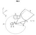
- Figur 2
- eine vergrößerte Ansicht des unteren Bereichs derVorrichtung gemäß Figur 1;
- Figur 3
- die Ansicht gemäß Figur 2 betrachtet aus einer anderenPerspektive;
- Figur 4
- eine perspektivische Ansicht eines zweiten Ausführungsbeispielsder erfindungsgemäßen Vorrichtung;
- Figur 5
- eine perspektivische Ansicht eines dritten Ausführungsbeispielsder erfindungsgemäßen Vorrichtung;und
- Figur 6
- eine perspektivische Ansicht eines vierten Ausführungsbeispielsder erfindungsgemäßen Vorrichtung.
- Figure 1
- a perspective view of a first embodiment of the device according to the invention;
- Figure 2
- an enlarged view of the lower region of the device according to Figure 1;
- Figure 3
- the view of Figure 2 viewed from a different perspective;
- Figure 4
- a perspective view of a second embodiment of the device according to the invention;
- Figure 5
- a perspective view of a third embodiment of the device according to the invention; and
- Figure 6
- a perspective view of a fourth embodiment of the device according to the invention.
In den Figuren 1, 2 und 3 ist ein erstes Ausführungsbeispielder erfindungsgemäßen Vorrichtung dargestellt, wobei die erfindungsgemäßeVorrichtung allgemein mit 10 bezeichnet ist.Diese ist als Stift ausgebildet und umfasst einen im Wesentlichenzylindrischen Schaft 12 sowie eine kegelförmige Spitze14. Die kegelförmige Spitze ist an ihrem in den Figuren 1 bis3 tiefstliegenden Punkt mit einem verschleißfesten Kugelkörper16, beispielsweise aus Metall oder dergleichen, versehen.Der verschleißfeste Kugelkörper 16 hat einen kleinen Durchmesser,beispielsweise von 1mm, und sitzt fest auf der kegelförmigenSpitze 14.In Figures 1, 2 and 3 is a first embodimentshown the inventive device, the inventiveDevice is generally designated 10.This is designed as a pin and essentially comprises one
An der kegelförmigen Spitze 14 ist ein erster Fortsatz 18 angeordnet,an dessen spitzenfernem Ende ein sphärischer Körper20 angebracht ist. In dem sphärischen Körper 20 ist ein alsLaserprojektor 21 ausgebildeter Beamer angeordnet, welcherauf einer von der X- und Y-Achse aufgespannten Oberfläche eindurch strichlierte Umrandung 22 eingegrenztes Projektionsfeld,dessen Größe sich durch den Öffnungswinkel α des Projektorsbestimmt, durch Projektion abdecken kann. Ferner istan der Spitze 14 der Vorrichtung 10 an einer zu der Anbringstelledes Fortsatzes 18 entgegengesetzten Seite ein zweiterFortsatz 24 angeordnet, welcher bei der in Figur 1 gezeigten Schrägstellung der erfindungsgemäßen Vorrichtung im Raum imWesentlichen orthogonal zu der von der X- und Y-Achse aufgespanntenOberfläche gerichtet ist. In dem Fortsatz 24 ist einoptischer Bewegungssensor 25 aufgenommen, der durch optischeMessungen vermittels des Strahlengangs 26 Bewegungen der Vorrichtung10, insbesondere des Kugelkörpers 16 auf der durchdie X- und Y-Achse aufgespannten Oberfläche erfasst.A
Die Vorrichtung funktioniert derart, dass der Schaft 12 mitseiner Spitze 14 und dem Kugelkörper 16 wie ein herkömmlicherStift auf der von der X- und Y-Achse aufgespannten Ebene bewegtwird, um beispielsweise, wie in Figur 1 dargestellt,einzelne Buchstaben 28, 30 zu schreiben. Diese Bewegung dessphärischen Körpers 20 auf der durch die X- und Y-Achse aufgespanntenOberfläche wird durch den in dem Fortsatz 24 aufgenommenenBewegungssensor 25 vermittels des Strahlengangs 26in für einen optischen Sensor herkömmlicher Weise erfasst,beispielsweise durch Erfassung einer bewegungsabhängigen Veränderungder Oberflächenstruktur, und an eine Datenverarbeitungseinheit32 übertragen. Diese verarbeitet die erfasstenPositionsdaten, unterzieht diese verschiedenen Prozeduren,beispielsweise einer Zeichenerkennungs-Verarabeitungsprozedurund kommt - wie in dem in Figur 1 gezeigten Beispielsfall -zu dem Ergebnis, dass mit der mit stiftförmigen Vorrichtung10 die Buchstaben "a" und "h" auf die von der X- und Y-Achseaufgespannte Oberfläche gezeichnet wurden.The device works in such a way that the
Die Datenverarbeitungseinheit 32 gibt dann entsprechende Signalean den in dem sphärischen Körper 20 positionierten Projektor21. Dieser projiziert, wie beispielhaft durch dieStrahlen 34 dargestellt, die von der Datenverarbeitungseinheit32 erfassten Buchstaben innerhalb der Projektionsfläche22 auf die von X- und Y-Achse aufgespannte Oberfläche, sodass ein Benutzer den Eindruck erhält, dass er mit dem sphärischenKörper 20 auf die von der X- und Y-Ebene aufgespannteOberfläche die Zeichen 28 und 30 geschrieben hätte. Bei jederBewegung der Vorrichtung 10, welche von den im Fortsatz 24 aufgenommenen Positionserfassungsmitteln 25 erfasst wird,werden die von der Datenverarbeitungseinheit 32 berechnetenDaten derart dem in dem sphärischen Körper 20 untergebrachtenProjektor 21 bereitgestellt, dass dieser trotz der Bewegungder Vorrichtung 10 die Zeichen 28 und 30 und ggf. weitere geschriebeneZeichen auf der von der X- und Y-Achse aufgespanntenOberfläche ortsstabil und lagestabil verharren. Mit anderenWorten wird die bei einer Schreibbewegung durchgeführteVerlagerung der stiftförmigen Vorrichtung 10 innerhalb der X-undY-Ebene von in Figur 1 links nach rechts derart bei derProjektion berücksichtigt, dass trotz der korrespondierendenBewegung des in dem sphärischen Körper 20 untergebrachtenProjektors 21 und damit der korrespondierenden Bewegung desProjektionsfeldes 22 die Zeichen 28 und 30 auf der von der X-undY-Achse aufgespannten Oberfläche orts- und lagestabilbleiben, so dass sich die Zeichen 28 und 30 innerhalb desProjektionsfeldes 22 entgegengesetzt zu der Bewegung der Vorrichtung10 von links nach rechts in Richtung von rechts nachlinks bewegen.The
Figur 3 ist noch zu entnehmen, dass der Projektor 21 nur miteinem ganz bestimmten Öffnungswinkel α der äußersten Strahlen231 und 232 projizieren kann, durch welche das Projektionsfeld,welches durch die Umrandung 22 begrenzt ist, definiertwird. Ferner ist Figur 3 deutlich zu entnehmen, dassdie Spitze 14 einen kegelförmigen Schatten in die Projektionsflächewirft, welcher Schatten von dem Projektor 21 nichterreicht werden kann.FIG. 3 also shows that the
Ferner ist noch darauf hinzuweisen, dass die Vorrichtung 10von einem Akkumulator 36 energetisch versorgt wird und einmit der Datenverarbeitungseinheit verbundenes Funkmodul 38zur Funkkommunikation, insbesondere Funkübertragung der erfasstenPositionsdaten oder ermittelten Zeichen, mit einerBasistation aufweist.It should also be pointed out that the
Figur 4 zeigt nun ein zweites Ausführungsbeispiel der vorliegendenErfindung. Es werden dieselben Bezugszeichen wie vorangehendbei der Beschreibung des ersten Ausführungsbeispielsanhand der Figuren 1 bis 3 verwendet, jedoch mit derZiffer 1 vorangestellt.Figure 4 now shows a second embodiment of the presentInvention. The same reference numerals are used as beforein the description of the first embodimentused with reference to Figures 1 to 3, but with thePreceded by
Zur Vermeidung von Wiederholungen werden lediglich die wesentlichenUnterschiede zu dem ersten Ausführungsbeispiel beschrieben.Der in Figur 4 gezeigte Ausschnitt der erfindungsgemäßenVorrichtung 110 zeigt lediglich einen Teil der Spitze114, welche, wie mit Bezug auf Figur 1 bereits erläutert, denFortsatz 124 trägt. In diesem Fortsatz ist entsprechend demersten Ausführungsbeispiel gemäß der Figuren 1 bis 3 der Positionserfassungssensor125 aufgenommen. Von diesem Positionserfassungssensor125 gehen die Strahlen 126 zur Positionserfassungaus. Im Unterschied zu dem mit Bezug auf die Figuren1 bis 3 beschriebenen ersten Ausführungsbeispiel ist derFortsatz 118 nicht unmittelbar an der Spitze 114 an einer imFortsatz 124 entgegengesetzten Stelle angebracht, sondern andem Fortsatz 124 selbst angebracht. Dadurch wird erreicht,dass der Fortsatz 118 sowie der an dessen freien Ende angebrachtesphärische Körper 120, in welchem der Projektor 121positioniert ist, nicht die Sicht auf die in dem Projektionsfeld122 geschriebenen Zeichen verdeckt. Vielmehr liegen sowohlder Fortsatz 124 als auch der Fortsatz 118 mit seinemsphärischen Körper 120 in einem Bereich, welcher bei Schrägstellungder erfindungsgemäßen Vorrichtung 110 ohnehin vonder Spitze 114 und dem nicht gezeigten Schaft bedeckt ist, sodass ein Nutzer dieselbe, allein durch die Stiftabmessungengeringfügig eingeschränkte Sicht auf die zu beschreibende Oberflächehat, wie dies bei einem herkömmlichen Schreibstiftder Fall ist.To avoid repetitions, only the essential onesDifferences from the first embodiment described.The section shown in Figure 4 of the
Die Funktionsweise der erfindungsgemäßen Vorrichtung gemäßdem zweiten Ausführungsbeispiel - wie in Figur 4 gezeigt -entspricht im Wesentlichen der Funktionsweise gemäß dem erstenAusführungsbeispiel. Es sei jedoch darauf hingewiesen, dass durch die Art der Anbringung des Fortsatzes 118 mit demden Projektor 121 tragenden sphärischen Körper 120 sich gegenüberdem ersten Ausführungsbeispiel veränderte Verhältnissehinsichtlich des Schattenwurfs ergeben. Bei der in Figur 4gezeigten Ausführungsform ist ein gegenüber dem ersten Ausführungsbeispielgemäß der Figuren 1 bis 3 verringerterSchattenwurf innerhalb des Projektionsfeldes 122 durch dieSpitze 114 zu erwarten.The operation of the device according to the inventionthe second embodiment - as shown in Figure 4 -corresponds essentially to the functioning according to the firstEmbodiment. However, it should be notedthat by the way the
Figur 5 zeigt nun ein drittes Ausführungsbeispiel der vorliegendenErfindung, welches sich an dem Ausführungsbeispiel,wie es in Figur 4 gezeigt ist, anlehnt. Wiederum werden dieselbenBezugszeichen wie für die Beschreibung der Ausführungsbeispielegemäß der Figuren 1 bis 4 verwendet, jedochmit der Ziffer 2 vorangestellt.Figure 5 now shows a third embodiment of the presentInvention, which is based on the embodiment,as shown in Figure 4. Again they become the sameReference symbols as for the description of the exemplary embodimentsused according to Figures 1 to 4, howeverpreceded by the number 2.
Der Unterschied zu dem Ausführungsbeispiel gemäß Figur 4liegt darin, dass an dem Fortsatz 224, welcher sich von Spitze214 aus in Richtung nach unten erstreckt, neben dem Fortsatz118 mit seinem sphärischen Körper 220 ein weiterer Fortsatz240 mit einem weiteren sphärischen Körper 242 angeordnetist, wobei in dem sphärischen Körper 242 ein weiterer Projektoraufgenommen ist. Die beiden Fortsätze 220 und 240 sindderart an dem Fortsatz 224 angebracht, dass ihre Längsachseneinen spitzen Winkel miteinander einschließen. Dadurch wirderreicht, dass die beiden den sphärischen Körpern 220 und 242zugeordneten Projektoren (nicht gezeigt) zwei Projektionsfeldererzeugen, deren Grenzen in Figur 5 durch die beiden Linien222 und 244 teilweise dargestellt sind. Diese beidenProjektionsflächen bilden Teilflächen einer Projektionsgesamtfläche,die zur Darstellung des Projektionsbildes, insbesonderezur Darstellung der Zeichen 228 und 230 genutzt werdenkann. Die beiden Projektionsteilflächen überlappen sichteilweise. Der Vorteil des in Figur 5 gezeigten Ausführungsbeispielsliegt darin, dass die von den Projektionsteilflächengebildete Gesamtprojektionsfläche größer ist als diesmit einem einzigen Projektor möglich ist, und dass somit ein großflächigeres Projektionsbild und letztendlich eine größereZeichenzahl dargestellt werden kann.The difference from the exemplary embodiment according to FIG. 4is that on the
Figur 6 zeigt nun ein viertes Ausführungsbeispiel der vorliegendenErfindung, welches sich an das dritte Ausführungsbeispielgemäß Figur 5 anlehnt. Wiederum werden dieselben Bezugszeichenwie in der vorangehenden Beschreibung verwendet,jedoch mit der Ziffer 3 vorangestellt.Figure 6 now shows a fourth embodiment of the presentInvention, which is the third embodimentaccording to FIG. 5. Again, the same reference numeralsas used in the previous description,however prefixed with the number 3.
Die Darstellung gemäß Figur 6 entspricht einer perspektivischenAnsicht in Schreibrichtung. Wiederum ist nur die Spitze314 der erfindungsgemäßen Vorrichtung 310 gezeigt. Der Unterschiedzu der in Figur 5 gezeigten dritten Ausführungsformliegt bei der in Figur 6 gezeigten vierten Ausführungsformdarin, dass der untere Teil der Spitze 314 durch Aussparungen350 und 352 volumenreduziert wurde, so dass der Schattenwurfdurch die Spitze 314 innerhalb des Gesamtprojektionsfeldes- definiert durch die Linien 322 und 344 - kleiner wird.The representation according to FIG. 6 corresponds to a perspectiveView in writing direction. Again, only the top is314 of the
Die Funktionsweise des Ausführungsbeispiels gemäß Figur 6entspricht der des Ausführungsbeispiels gemäß Figur 5, dasheißt, es werden mit zwei Projektoren, die in den sphärischenKörpern 320 und 342 aufgenommen sind, zwei Teilprojektionsflächenerzeugt, die eine Gesamtprojektionsfläche ergeben.The mode of operation of the exemplary embodiment according to FIG. 6corresponds to that of the embodiment according to FIGmeans there will be two projectors working in the
Claims (19)
Translated fromGermanwobei diese in Form eines Stiftes ausgeführt ist.Device (10; 110; 210; 310) according to claim 1,
which is in the form of a pin.
wobei der Bezugspunkt (16; 116; 216; 316) von einer Stiftspitze,insbesondere von einer druckstabilisierten Stiftspitze,gebildet ist.Device (10; 110; 210; 310) according to claim 2,
the reference point (16; 116; 216; 316) being formed by a pen tip, in particular by a pressure-stabilized pen tip.
wobei die Positionserfassungsmittel (25; 125) oder/und dieProjektionsmittel (21; 121) an einer der Stiftspitze nahenStelle der Vorrichtung (10; 110; 210; 310) angeordnet sind.Device (10; 110; 210; 310) according to claim 3,
wherein the position detection means (25; 125) and / or the projection means (21; 121) are arranged at a location of the device (10; 110; 210; 310) near the pen tip.
wobei die Positionserfassungsmittel mit wenigstens einem optischenSensor (25; 125) oder/und mit wenigstens einem mechanischen Sensor oder/und mit wenigstens einem Beschleunigungssensor,oder/und mit einer Kombination dieser Sensoren ausgeführtsind.Device (10; 110; 210; 310) according to one of the preceding claims,
the position detection means being designed with at least one optical sensor (25; 125) or / and with at least one mechanical sensor or / and with at least one acceleration sensor, or / and with a combination of these sensors.
wobei der wenigstens eine optische Sensor (25; 125) als optischerBewegungssensor zur Erfassung einer translatorischenBewegung des Bezugspunktes (16; 116; 216; 316) ausgeführtist.Device (10; 110; 210; 310) according to claim 5,
wherein the at least one optical sensor (25; 125) is designed as an optical movement sensor for detecting a translational movement of the reference point (16; 116; 216; 316).
wobei der wenigstens eine optische Sensor (25; 125) zur Erfassungeiner rotatorischen Bewegung um eine sich durch denBezugspunkt (16; 116; 216; 316) erstreckende Achse ausgeführtist.Device (10; 110; 210; 310) according to claim 5 or 6,
wherein the at least one optical sensor (25; 125) is designed to detect a rotational movement about an axis extending through the reference point (16; 116; 216; 316).
wobei der wenigstens eine mechanische Sensor als Rollsensorzur Erfassung einer Abrollbewegung auf der Oberfläche ausgeführtist.Device (10; 110; 210; 310) according to one of claims 5 to 7,
wherein the at least one mechanical sensor is designed as a roll sensor for detecting a rolling movement on the surface.
wobei der wenigstens eine Beschleunigungssensor als Drehwinkel-Beschleunigungssensoroder als Longitudinal-Beschleunigungssensorzur Erfassung einer Beschleunigung desBezugspunktes der Vorrichtung ausgeführt ist.Device (10; 110; 210; 310) according to one of claims 5 to 8,
wherein the at least one acceleration sensor is designed as a rotation angle acceleration sensor or as a longitudinal acceleration sensor for detecting an acceleration of the reference point of the device.
wobei die Datenverarbeitungsmittel (32) einen Mikroprozessorumfassen.Device (10; 110; 210; 310) according to one of the preceding claims,
said data processing means (32) comprising a microprocessor.
wobei die Projektionsmittel (21; 121) mit wenigstens einemLaserprojektor ausgeführt sind.Device (10; 110; 210; 310) according to one of the preceding claims,
the projection means (21; 121) being designed with at least one laser projector.
wobei der wenigstens eine Laserprojektor (21; 121) an einerdem Bezugspunkt, insbesondere der Stiftspitze (10; 110; 210;310), nahen Stelle angeordnet ist.Device (10; 110; 210; 310) according to claim 11, in particular according to claims 3 and 11,
wherein the at least one laser projector (21; 121) is arranged at a location close to the reference point, in particular the pen tip (10; 110; 210; 310).
wobei der Laserprojektor an einer dem Bezugspunkt, insbesondereder Stiftspitze, fernen Stelle angeordnet ist und wobeidem Laserprojektor ein optisches Übertragungssystem, insbesondereeine Linsenanordnung oder/und Lichtleitmittel oder/undSpiegelanordnungen oder dergleichen, zur Projektiondes Projektionsbildes auf die Oberfläche zugeordnet ist.Device according to claim 11, in particular according to claims 3 and 11,
wherein the laser projector is arranged at a point remote from the reference point, in particular the pen tip, and wherein the laser projector is assigned an optical transmission system, in particular a lens arrangement and / or light guide means and / or mirror arrangements or the like, for projecting the projection image onto the surface.
wobei die Projektionsmittel mit einer Mehrzahl von Laserprojektorenausgeführt ist.Device (210; 310) according to one of claims 11 - 13,
wherein the projection means is implemented with a plurality of laser projectors.
wobei die Laserprojektoren derart angeordnet sind und zusammenwirken,dass das Projektionsbild aus von einzelnen Projektorenerzeugten Teilprojektionsbildern (222, 244; 322, 344)zusammengesetzt ist.Device (210; 310) according to claim 14,
the laser projectors being arranged and interacting in such a way that the projection image is composed of partial projection images (222, 244; 322, 344) generated by individual projectors.
wobei die Projektionsmittel (21; 121) das Projektionsbild(28, 30) innerhalb einer Projektionsfläche auf die Oberfläche(XY) projizieren, wobei weiter sich die Projektionsfläche(22) auf der Oberfläche (XY) korrespondierend zu der Änderungder gegenwärtigen Position des Bezugspunktes (16; 116; 216;316) bewegt und wobei die Datenverarbeitungsmittel (32) zumErreichen der Orts- und Lagestabilität des Projektionsbildes (28, 30) auf der Oberfläche (XY) das Projektionsbild (28, 30)mit einer der Änderung der gegenwärtigen Position des Bezugspunktes(16) entgegengesetzten Komplementärbewegung innerhalbder Projektionsfläche bewegen.Device (10; 110; 210; 310) according to one of the preceding claims,
the projection means (21; 121) projecting the projection image (28, 30) onto the surface (XY) within a projection surface, the projection surface (22) on the surface (XY) corresponding to the change in the current position of the reference point ( 16; 116; 216; 316) and wherein the data processing means (32) for achieving the position and position stability of the projection image (28, 30) on the surface (XY) move the projection image (28, 30) with a change in the current position of the reference point (16) move opposite complementary movement within the projection surface.
wobei die Datenverarbeitungsmittel (32) mit einer Einrichtungzur Zeichenerkennung ausgebildet sind, welche die von den Positionserfassungsmitteln(25) erfasste Änderung der gegenwärtigenPosition des Bezugspunktes (16) auf eine Übereinstimmungmit vorbestimmten Zeichen untersucht und dieser bei wesentlicherÜbereinstimmung wenigstens ein Zeichen zuordnet.Device (10; 110; 210; 310) according to one of the preceding claims,
wherein the data processing means (32) are designed with a device for character recognition which examines the change in the current position of the reference point (16) detected by the position detection means (25) for a match with predetermined characters and, if there is a substantial match, assigns it to at least one character.
wobei diese zur kabelgebundenen oder kabellosen Kommunikationmit einer entfernt angeordneten Basis ausgebildet ist.Device (10; 110; 210; 310) according to one of the preceding claims, in particular according to claim 17,
which is designed for wired or wireless communication with a remotely located base.
Priority Applications (10)
| Application Number | Priority Date | Filing Date | Title |
|---|---|---|---|
| EP01124524AEP1302891A1 (en) | 2001-10-12 | 2001-10-12 | Apparatus for the detection and display of motion |
| EP01130738AEP1302892A1 (en) | 2001-10-11 | 2001-12-21 | Apparatus for the registration and representation of movements |
| CNA028201728ACN1568480A (en) | 2001-10-12 | 2002-10-02 | Device for detecting and representing movements |
| ES02777284TES2252520T3 (en) | 2001-10-12 | 2002-10-02 | DEVICE FOR RECEIVING AND REPRESENTING MOVEMENTS. |
| DE50205380TDE50205380D1 (en) | 2001-10-12 | 2002-10-02 | DEVICE FOR DETECTING AND PRESENTING MOVEMENTS |
| JP2003536978AJP2005505867A (en) | 2001-10-12 | 2002-10-02 | Device for detecting and displaying movement |
| US10/492,621US7286706B2 (en) | 2001-10-12 | 2002-10-02 | Device for detecting and representing movements |
| EP02777284AEP1435064B1 (en) | 2001-10-12 | 2002-10-02 | Device for detecting and representing movements |
| KR10-2004-7005294AKR20040048421A (en) | 2001-10-12 | 2002-10-02 | Device for detecting and representing movements |
| PCT/EP2002/011095WO2003034323A1 (en) | 2001-10-12 | 2002-10-02 | Device for detecting and representing movements |
Applications Claiming Priority (1)
| Application Number | Priority Date | Filing Date | Title |
|---|---|---|---|
| EP01124524AEP1302891A1 (en) | 2001-10-12 | 2001-10-12 | Apparatus for the detection and display of motion |
Publications (1)
| Publication Number | Publication Date |
|---|---|
| EP1302891A1true EP1302891A1 (en) | 2003-04-16 |
Family
ID=8178956
Family Applications (2)
| Application Number | Title | Priority Date | Filing Date |
|---|---|---|---|
| EP01124524AWithdrawnEP1302891A1 (en) | 2001-10-11 | 2001-10-12 | Apparatus for the detection and display of motion |
| EP02777284AExpired - LifetimeEP1435064B1 (en) | 2001-10-12 | 2002-10-02 | Device for detecting and representing movements |
Family Applications After (1)
| Application Number | Title | Priority Date | Filing Date |
|---|---|---|---|
| EP02777284AExpired - LifetimeEP1435064B1 (en) | 2001-10-12 | 2002-10-02 | Device for detecting and representing movements |
Country Status (8)
| Country | Link |
|---|---|
| US (1) | US7286706B2 (en) |
| EP (2) | EP1302891A1 (en) |
| JP (1) | JP2005505867A (en) |
| KR (1) | KR20040048421A (en) |
| CN (1) | CN1568480A (en) |
| DE (1) | DE50205380D1 (en) |
| ES (1) | ES2252520T3 (en) |
| WO (1) | WO2003034323A1 (en) |
Cited By (4)
| Publication number | Priority date | Publication date | Assignee | Title |
|---|---|---|---|---|
| EP1533685A1 (en)* | 2003-10-22 | 2005-05-25 | Sony International (Europe) GmbH | Handheld device for navigating and displaying data |
| WO2005109163A3 (en)* | 2004-05-04 | 2006-01-05 | Siemens Ag | Method and device for controlling display content of a display device display area |
| WO2005109162A3 (en)* | 2004-05-05 | 2006-02-02 | Siemens Ag | Device for detecting and representing movements |
| EP1735588A4 (en)* | 2004-03-08 | 2016-09-28 | Electronic Scripting Products | Apparatus and method for determining orientation parameters of an elongate object |
Families Citing this family (15)
| Publication number | Priority date | Publication date | Assignee | Title |
|---|---|---|---|---|
| US20050264525A1 (en)* | 2004-05-27 | 2005-12-01 | Adams Charles R | Mouse pointing system/icon identification system |
| WO2007046604A1 (en)* | 2005-10-19 | 2007-04-26 | Mobisol Inc. | Device for inputting digital information |
| KR101424157B1 (en)* | 2005-12-10 | 2014-07-31 | 박순영 | A pen-shaped electronic dictionary with a built-in laser projector |
| KR101310515B1 (en)* | 2006-05-17 | 2013-09-25 | 정병주 | Method and device for character entry, using projection keyboard |
| WO2008002239A1 (en)* | 2006-06-28 | 2008-01-03 | Anoto Ab | Operation control and data processing in an electronic pen |
| GB2440921A (en)* | 2006-07-31 | 2008-02-20 | Hewlett Packard Development Co | A digital pen incorporating an orientation and position sensor and a display projector |
| WO2009096886A1 (en)* | 2008-01-28 | 2009-08-06 | Anoto Ab | Digital pens and a method for digital recording of information |
| JP2009271910A (en)* | 2008-04-08 | 2009-11-19 | Seiko Epson Corp | Pointing device and information projection system |
| US20090309854A1 (en)* | 2008-06-13 | 2009-12-17 | Polyvision Corporation | Input devices with multiple operating modes |
| US9141955B2 (en)* | 2010-06-23 | 2015-09-22 | The Western Union Company | Biometrically secured user input for forms |
| CN101882001B (en)* | 2010-07-20 | 2011-11-09 | 鸿富锦精密工业(深圳)有限公司 | Motion sensor and electronic device with same |
| JP5598232B2 (en)* | 2010-10-04 | 2014-10-01 | ソニー株式会社 | Information processing apparatus, information processing system, and information processing method |
| CN102141846A (en)* | 2011-03-09 | 2011-08-03 | 中兴通讯股份有限公司 | Method for intuitively browsing contents and mobile terminal |
| CN103946773A (en)* | 2011-08-29 | 2014-07-23 | S·瓦利切克 | Multifunction pen input peripheral computer controller |
| CN107618290A (en)* | 2017-08-25 | 2018-01-23 | 触景无限科技(北京)有限公司 | Smart pen |
Citations (4)
| Publication number | Priority date | Publication date | Assignee | Title |
|---|---|---|---|---|
| EP0693739A2 (en)* | 1994-07-13 | 1996-01-24 | YASHIMA ELECTRIC CO., Ltd. of ISHIHARA NOGAMI | Method and apparatus capable of storing and reproducing handwriting |
| JPH08160539A (en)* | 1994-12-08 | 1996-06-21 | Nikon Corp | Light blackboard |
| DE19543959A1 (en)* | 1995-11-25 | 1997-05-28 | P & I Gmbh | Writing and control-desk for computer-assisted information projection e.g. for lectures |
| WO2000000928A1 (en)* | 1998-06-26 | 2000-01-06 | Lci/Smartpen, N.V. | Apparatus and methods for imaging written information with a mobile telephone set |
Family Cites Families (36)
| Publication number | Priority date | Publication date | Assignee | Title |
|---|---|---|---|---|
| US4111536A (en)* | 1976-06-30 | 1978-09-05 | The Singer Company | Automatic registration of projector images |
| US4345239A (en)* | 1980-06-20 | 1982-08-17 | International Business Machines Corporation | Apparatus for determining pen acceleration |
| US4972496A (en)* | 1986-07-25 | 1990-11-20 | Grid Systems Corporation | Handwritten keyboardless entry computer system |
| AU7586187A (en)* | 1986-10-06 | 1988-04-21 | Stefan Grigore De Fay | Method and portable device for acquiring, storing and optionally processing and reproducing graphic signs from any medium |
| US5194852A (en)* | 1986-12-01 | 1993-03-16 | More Edward S | Electro-optic slate for direct entry and display and/or storage of hand-entered textual and graphic information |
| JPH0381817A (en)* | 1989-08-25 | 1991-04-08 | Hitachi Ltd | Handwritten input information processing device and handwritten input information system using this handwritten input information processing device |
| US5294792A (en)* | 1991-12-31 | 1994-03-15 | Texas Instruments Incorporated | Writing tip position sensing and processing apparatus |
| CA2149213A1 (en)* | 1992-11-17 | 1994-05-26 | Thomas Debuisser | Method and device for capturing and processing graphical information |
| US6655597B1 (en)* | 2000-06-27 | 2003-12-02 | Symbol Technologies, Inc. | Portable instrument for electro-optically reading indicia and for projecting a bit-mapped color image |
| JPH0713105A (en)* | 1993-06-22 | 1995-01-17 | Atr Tsushin Syst Kenkyusho:Kk | Observer follow-up type stereoscopic display device |
| US5528263A (en)* | 1994-06-15 | 1996-06-18 | Daniel M. Platzker | Interactive projected video image display system |
| US5838819A (en)* | 1995-11-14 | 1998-11-17 | Lucent Technologies Inc. | System and method for processing and managing electronic copies of handwritten notes |
| JPH09146691A (en)* | 1995-11-17 | 1997-06-06 | Hitachi Ltd | Information processing device |
| US6079862A (en)* | 1996-02-22 | 2000-06-27 | Matsushita Electric Works, Ltd. | Automatic tracking lighting equipment, lighting controller and tracking apparatus |
| US6686910B2 (en)* | 1996-04-22 | 2004-02-03 | O'donnell, Jr. Francis E. | Combined writing instrument and digital documentor apparatus and method of use |
| US6460766B1 (en)* | 1996-10-28 | 2002-10-08 | Francis Olschafskie | Graphic symbols and method and system for identification of same |
| DE19708240C2 (en)* | 1997-02-28 | 1999-10-14 | Siemens Ag | Arrangement and method for detecting an object in a region illuminated by waves in the invisible spectral range |
| GB2329300B (en) | 1997-09-16 | 2002-07-17 | Nokia Mobile Phones Ltd | Mobile telephone with handwritten data input |
| US6330976B1 (en)* | 1998-04-01 | 2001-12-18 | Xerox Corporation | Marking medium area with encoded identifier for producing action through network |
| US6985643B1 (en)* | 1998-04-30 | 2006-01-10 | Anoto Group Ab | Device and method for recording hand-written information |
| US20010025289A1 (en)* | 1998-09-25 | 2001-09-27 | Jenkins Michael D. | Wireless pen input device |
| US7079712B1 (en)* | 1999-05-25 | 2006-07-18 | Silverbrook Research Pty Ltd | Method and system for providing information in a document |
| US6504956B1 (en)* | 1999-10-05 | 2003-01-07 | Ecrio Inc. | Method and apparatus for digitally capturing handwritten notes |
| JP4332964B2 (en)* | 1999-12-21 | 2009-09-16 | ソニー株式会社 | Information input / output system and information input / output method |
| WO2001052230A1 (en)* | 2000-01-10 | 2001-07-19 | Ic Tech, Inc. | Method and system for interacting with a display |
| JP3994672B2 (en)* | 2000-03-31 | 2007-10-24 | セイコーエプソン株式会社 | Detection of indicated position using image processing |
| JP3867512B2 (en)* | 2000-06-29 | 2007-01-10 | 富士ゼロックス株式会社 | Image processing apparatus, image processing method, and program |
| US6707444B1 (en)* | 2000-08-18 | 2004-03-16 | International Business Machines Corporation | Projector and camera arrangement with shared optics and optical marker for use with whiteboard systems |
| US6567076B2 (en)* | 2001-01-10 | 2003-05-20 | Chenming Mold Ind. Corp. | Hand-writing input and recording device |
| US6657618B2 (en)* | 2001-01-23 | 2003-12-02 | Eloise Gatewood-Moore | Optical memory unit for capturing complete analog motion |
| US7203383B2 (en)* | 2001-02-22 | 2007-04-10 | Thinkpen Llc | Handwritten character recording and recognition device |
| US7257255B2 (en)* | 2001-11-21 | 2007-08-14 | Candledragon, Inc. | Capturing hand motion |
| GB2382879A (en)* | 2001-12-06 | 2003-06-11 | Hewlett Packard Co | Image capture device with capture field illumination |
| US20040047505A1 (en)* | 2001-12-26 | 2004-03-11 | Firooz Ghassabian | Stylus computer |
| JP4050055B2 (en)* | 2002-01-10 | 2008-02-20 | 株式会社リコー | Handwritten character batch conversion apparatus, handwritten character batch conversion method, and program |
| US7036938B2 (en)* | 2002-10-31 | 2006-05-02 | Microsoft Corporation | Pen projection display |
- 2001
- 2001-10-12EPEP01124524Apatent/EP1302891A1/ennot_activeWithdrawn
- 2002
- 2002-10-02USUS10/492,621patent/US7286706B2/ennot_activeExpired - Lifetime
- 2002-10-02KRKR10-2004-7005294Apatent/KR20040048421A/ennot_activeCeased
- 2002-10-02JPJP2003536978Apatent/JP2005505867A/enactivePending
- 2002-10-02DEDE50205380Tpatent/DE50205380D1/ennot_activeExpired - Fee Related
- 2002-10-02ESES02777284Tpatent/ES2252520T3/ennot_activeExpired - Lifetime
- 2002-10-02CNCNA028201728Apatent/CN1568480A/enactivePending
- 2002-10-02EPEP02777284Apatent/EP1435064B1/ennot_activeExpired - Lifetime
- 2002-10-02WOPCT/EP2002/011095patent/WO2003034323A1/enactiveIP Right Grant
Patent Citations (4)
| Publication number | Priority date | Publication date | Assignee | Title |
|---|---|---|---|---|
| EP0693739A2 (en)* | 1994-07-13 | 1996-01-24 | YASHIMA ELECTRIC CO., Ltd. of ISHIHARA NOGAMI | Method and apparatus capable of storing and reproducing handwriting |
| JPH08160539A (en)* | 1994-12-08 | 1996-06-21 | Nikon Corp | Light blackboard |
| DE19543959A1 (en)* | 1995-11-25 | 1997-05-28 | P & I Gmbh | Writing and control-desk for computer-assisted information projection e.g. for lectures |
| WO2000000928A1 (en)* | 1998-06-26 | 2000-01-06 | Lci/Smartpen, N.V. | Apparatus and methods for imaging written information with a mobile telephone set |
Non-Patent Citations (1)
| Title |
|---|
| PATENT ABSTRACTS OF JAPAN vol. 1996, no. 10 31 October 1996 (1996-10-31)* |
Cited By (7)
| Publication number | Priority date | Publication date | Assignee | Title |
|---|---|---|---|---|
| EP1533685A1 (en)* | 2003-10-22 | 2005-05-25 | Sony International (Europe) GmbH | Handheld device for navigating and displaying data |
| WO2005041017A3 (en)* | 2003-10-22 | 2006-02-23 | Conante Advanced Interface Sol | Handheld device for navigating and displaying data |
| GB2423685A (en)* | 2003-10-22 | 2006-08-30 | Conante Advanced Interface Sol | Handheld device for navigating and displaying data |
| GB2423685B (en)* | 2003-10-22 | 2008-05-07 | Conante Advanced Interface Sol | Handheld device for navigating and displaying data |
| EP1735588A4 (en)* | 2004-03-08 | 2016-09-28 | Electronic Scripting Products | Apparatus and method for determining orientation parameters of an elongate object |
| WO2005109163A3 (en)* | 2004-05-04 | 2006-01-05 | Siemens Ag | Method and device for controlling display content of a display device display area |
| WO2005109162A3 (en)* | 2004-05-05 | 2006-02-02 | Siemens Ag | Device for detecting and representing movements |
Also Published As
| Publication number | Publication date |
|---|---|
| EP1435064A1 (en) | 2004-07-07 |
| US20040247160A1 (en) | 2004-12-09 |
| WO2003034323A1 (en) | 2003-04-24 |
| DE50205380D1 (en) | 2006-01-26 |
| EP1435064B1 (en) | 2005-12-21 |
| KR20040048421A (en) | 2004-06-09 |
| US7286706B2 (en) | 2007-10-23 |
| ES2252520T3 (en) | 2006-05-16 |
| JP2005505867A (en) | 2005-02-24 |
| CN1568480A (en) | 2005-01-19 |
Similar Documents
| Publication | Publication Date | Title |
|---|---|---|
| EP1435064B1 (en) | Device for detecting and representing movements | |
| DE69321445T2 (en) | Electromagnetic graphic data acquisition system based on a code | |
| DE69428566T2 (en) | Coordinate input device | |
| DE69131816T2 (en) | Computer aided delivery system for training | |
| DE69033097T2 (en) | Portable graphing calculator | |
| DE69530395T2 (en) | INTERACTIVE PROJECTED VIDEO DISPLAY SYSTEM | |
| DE60023900T2 (en) | PRESENTATION SYSTEM FOR CALCULATOR AND OPTICAL TRACKING PROCEDURE OF A WIRELESS INDICATOR | |
| DE69629658T2 (en) | LIGHT PEN INPUT SYSTEMS | |
| DE3427658C2 (en) | ||
| DE10221415B4 (en) | Optical push-button screen pointing device | |
| DE10320557B4 (en) | Method and device for supporting activities to be carried out at a workshop workplace | |
| EP1456808B1 (en) | Device for detecting and displaying movements | |
| DE19822323C2 (en) | Tire marking device | |
| DE10230972A1 (en) | Device with means for determining the position of device parts | |
| DE3539720A1 (en) | ADAPTER FOR A PCB TEST DEVICE | |
| DE10008670C2 (en) | Wippschaltvorrichtung | |
| DE3418632C2 (en) | Coordinate recorder | |
| DE102006040259A1 (en) | Data processing device input device, in particular keyboard system and data processing device | |
| DE3686449T2 (en) | DEVICE FOR PREPARING MOUNTING SURFACES OF ORIGINALS TO BE SCANED. | |
| DE10231981A1 (en) | Imaging device for a microscope | |
| DE68924712T2 (en) | ELECTRONIC PANEL. | |
| DE19644109B4 (en) | Input device for capturing handwritten messages from paper to computer - has pen device with multiple sensors and bar code reader that detect page type and transmit pen movements to computer | |
| EP1983406A1 (en) | Method and device for data input in a data processing facility | |
| DE19602592A1 (en) | Control device for computer-aided information projection and recording | |
| DE2641965A1 (en) | TEST DEVICE FOR A PHOTOGRAMMETRICAL INSTRUMENT |
Legal Events
| Date | Code | Title | Description |
|---|---|---|---|
| PUAI | Public reference made under article 153(3) epc to a published international application that has entered the european phase | Free format text:ORIGINAL CODE: 0009012 | |
| AK | Designated contracting states | Designated state(s):AT BE CH CY DE DK ES FI FR GB GR IE IT LI LU MC NL PT SE TR | |
| AX | Request for extension of the european patent | Extension state:AL LT LV MK RO SI | |
| AKX | Designation fees paid | ||
| REG | Reference to a national code | Ref country code:DE Ref legal event code:8566 | |
| STAA | Information on the status of an ep patent application or granted ep patent | Free format text:STATUS: THE APPLICATION IS DEEMED TO BE WITHDRAWN | |
| 18D | Application deemed to be withdrawn | Effective date:20031017 |