EP1301123B1 - A skin electrode with a by-pass element - Google Patents
A skin electrode with a by-pass elementDownload PDFInfo
- Publication number
- EP1301123B1 EP1301123B1EP01951451AEP01951451AEP1301123B1EP 1301123 B1EP1301123 B1EP 1301123B1EP 01951451 AEP01951451 AEP 01951451AEP 01951451 AEP01951451 AEP 01951451AEP 1301123 B1EP1301123 B1EP 1301123B1
- Authority
- EP
- European Patent Office
- Prior art keywords
- electrically conductive
- conductive layer
- gel
- electrode according
- electrode
- Prior art date
- Legal status (The legal status is an assumption and is not a legal conclusion. Google has not performed a legal analysis and makes no representation as to the accuracy of the status listed.)
- Expired - Lifetime
Links
- 239000000463materialSubstances0.000claimsdescription21
- 229910052751metalInorganic materials0.000claimsdescription13
- 239000002184metalSubstances0.000claimsdescription13
- ATJFFYVFTNAWJD-UHFFFAOYSA-NTinChemical compound[Sn]ATJFFYVFTNAWJD-UHFFFAOYSA-N0.000claimsdescription9
- 239000002245particleSubstances0.000claimsdescription9
- 239000004411aluminiumSubstances0.000claimsdescription8
- 229910052782aluminiumInorganic materials0.000claimsdescription8
- XAGFODPZIPBFFR-UHFFFAOYSA-NaluminiumChemical compound[Al]XAGFODPZIPBFFR-UHFFFAOYSA-N0.000claimsdescription8
- 229910052718tinInorganic materials0.000claimsdescription8
- 239000011135tinSubstances0.000claimsdescription8
- 239000002253acidSubstances0.000claimsdescription7
- 150000003839saltsChemical class0.000claimsdescription7
- HCHKCACWOHOZIP-UHFFFAOYSA-NZincChemical compound[Zn]HCHKCACWOHOZIP-UHFFFAOYSA-N0.000claimsdescription4
- 239000011230binding agentSubstances0.000claimsdescription4
- 239000004020conductorSubstances0.000claimsdescription4
- 239000011133leadSubstances0.000claimsdescription4
- 229910052725zincInorganic materials0.000claimsdescription4
- 239000011701zincSubstances0.000claimsdescription4
- 229910021607Silver chlorideInorganic materials0.000claimsdescription3
- 239000004332silverSubstances0.000claimsdescription3
- 229910052709silverInorganic materials0.000claimsdescription3
- HKZLPVFGJNLROG-UHFFFAOYSA-Msilver monochlorideChemical compound[Cl-].[Ag+]HKZLPVFGJNLROG-UHFFFAOYSA-M0.000claimsdescription3
- OKTJSMMVPCPJKN-UHFFFAOYSA-NCarbonChemical compound[C]OKTJSMMVPCPJKN-UHFFFAOYSA-N0.000claimsdescription2
- 229910052799carbonInorganic materials0.000claimsdescription2
- 239000000203mixtureSubstances0.000claims2
- BQCADISMDOOEFD-UHFFFAOYSA-NSilverChemical compound[Ag]BQCADISMDOOEFD-UHFFFAOYSA-N0.000claims1
- 239000000126substanceSubstances0.000abstractdescription7
- 239000000499gelSubstances0.000description49
- 230000007797corrosionEffects0.000description10
- 238000005260corrosionMethods0.000description10
- 230000002378acidificating effectEffects0.000description9
- -1polyethylenePolymers0.000description8
- 239000000017hydrogelSubstances0.000description7
- 239000000758substrateSubstances0.000description6
- 230000006866deteriorationEffects0.000description4
- 229910052500inorganic mineralInorganic materials0.000description4
- 150000002500ionsChemical class0.000description4
- 150000002739metalsChemical class0.000description4
- 239000011707mineralSubstances0.000description4
- 229920000642polymerPolymers0.000description4
- 230000000638stimulationEffects0.000description4
- QTBSBXVTEAMEQO-UHFFFAOYSA-NAcetic acidChemical compoundCC(O)=OQTBSBXVTEAMEQO-UHFFFAOYSA-N0.000description3
- KWYUFKZDYYNOTN-UHFFFAOYSA-MPotassium hydroxideChemical compound[OH-].[K+]KWYUFKZDYYNOTN-UHFFFAOYSA-M0.000description3
- HEMHJVSKTPXQMS-UHFFFAOYSA-MSodium hydroxideChemical compound[OH-].[Na+]HEMHJVSKTPXQMS-UHFFFAOYSA-M0.000description3
- 239000002390adhesive tapeSubstances0.000description3
- 239000007789gasSubstances0.000description3
- 229920001477hydrophilic polymerPolymers0.000description3
- 150000007522mineralic acidsChemical class0.000description3
- 210000003205muscleAnatomy0.000description3
- 210000005036nerveAnatomy0.000description3
- 150000007524organic acidsChemical class0.000description3
- 229920003023plasticPolymers0.000description3
- 239000004033plasticSubstances0.000description3
- 229920000058polyacrylatePolymers0.000description3
- 238000005476solderingMethods0.000description3
- XLYOFNOQVPJJNP-UHFFFAOYSA-NwaterSubstancesOXLYOFNOQVPJJNP-UHFFFAOYSA-N0.000description3
- 229910000838Al alloyInorganic materials0.000description2
- QGZKDVFQNNGYKY-UHFFFAOYSA-NAmmoniaChemical compoundNQGZKDVFQNNGYKY-UHFFFAOYSA-N0.000description2
- PAYRUJLWNCNPSJ-UHFFFAOYSA-NAnilineChemical compoundNC1=CC=CC=C1PAYRUJLWNCNPSJ-UHFFFAOYSA-N0.000description2
- VEXZGXHMUGYJMC-UHFFFAOYSA-NHydrochloric acidChemical compoundClVEXZGXHMUGYJMC-UHFFFAOYSA-N0.000description2
- 241001465754MetazoaSpecies0.000description2
- 101100460844Mus musculus Nr2f6 geneProteins0.000description2
- 239000004952PolyamideSubstances0.000description2
- 239000004743PolypropyleneSubstances0.000description2
- WCUXLLCKKVVCTQ-UHFFFAOYSA-MPotassium chlorideChemical compound[Cl-].[K+]WCUXLLCKKVVCTQ-UHFFFAOYSA-M0.000description2
- JUJWROOIHBZHMG-UHFFFAOYSA-NPyridineChemical compoundC1=CC=NC=C1JUJWROOIHBZHMG-UHFFFAOYSA-N0.000description2
- FAPWRFPIFSIZLT-UHFFFAOYSA-MSodium chlorideChemical compound[Na+].[Cl-]FAPWRFPIFSIZLT-UHFFFAOYSA-M0.000description2
- 229910021626Tin(II) chlorideInorganic materials0.000description2
- 150000001450anionsChemical class0.000description2
- QVGXLLKOCUKJST-UHFFFAOYSA-Natomic oxygenChemical compound[O]QVGXLLKOCUKJST-UHFFFAOYSA-N0.000description2
- WPYMKLBDIGXBTP-UHFFFAOYSA-Nbenzoic acidChemical compoundOC(=O)C1=CC=CC=C1WPYMKLBDIGXBTP-UHFFFAOYSA-N0.000description2
- 230000008878couplingEffects0.000description2
- 238000010168coupling processMethods0.000description2
- 238000005859coupling reactionMethods0.000description2
- 238000000537electroencephalographyMethods0.000description2
- 239000003792electrolyteSubstances0.000description2
- 238000002567electromyographyMethods0.000description2
- 239000002923metal particleSubstances0.000description2
- BDAGIHXWWSANSR-UHFFFAOYSA-Nmethanoic acidNatural productsOC=OBDAGIHXWWSANSR-UHFFFAOYSA-N0.000description2
- 238000012544monitoring processMethods0.000description2
- 230000007935neutral effectEffects0.000description2
- 229910052760oxygenInorganic materials0.000description2
- 239000001301oxygenSubstances0.000description2
- 229920002647polyamidePolymers0.000description2
- 229920000193polymethacrylatePolymers0.000description2
- 229920001155polypropylenePolymers0.000description2
- IOLCXVTUBQKXJR-UHFFFAOYSA-Mpotassium bromideChemical compound[K+].[Br-]IOLCXVTUBQKXJR-UHFFFAOYSA-M0.000description2
- 238000002360preparation methodMethods0.000description2
- BDHFUVZGWQCTTF-UHFFFAOYSA-Nsulfonic acidChemical compoundOS(=O)=OBDHFUVZGWQCTTF-UHFFFAOYSA-N0.000description2
- 230000001225therapeutic effectEffects0.000description2
- 210000001519tissueAnatomy0.000description2
- 238000012546transferMethods0.000description2
- 238000003466weldingMethods0.000description2
- TXUICONDJPYNPY-UHFFFAOYSA-N(1,10,13-trimethyl-3-oxo-4,5,6,7,8,9,11,12,14,15,16,17-dodecahydrocyclopenta[a]phenanthren-17-yl) heptanoateChemical compoundC1CC2CC(=O)C=C(C)C2(C)C2C1C1CCC(OC(=O)CCCCCC)C1(C)CC2TXUICONDJPYNPY-UHFFFAOYSA-N0.000description1
- SMZOUWXMTYCWNB-UHFFFAOYSA-N2-(2-methoxy-5-methylphenyl)ethanamineChemical compoundCOC1=CC=C(C)C=C1CCNSMZOUWXMTYCWNB-UHFFFAOYSA-N0.000description1
- NIXOWILDQLNWCW-UHFFFAOYSA-N2-Propenoic acidNatural productsOC(=O)C=CNIXOWILDQLNWCW-UHFFFAOYSA-N0.000description1
- OSWFIVFLDKOXQC-UHFFFAOYSA-N4-(3-methoxyphenyl)anilineChemical compoundCOC1=CC=CC(C=2C=CC(N)=CC=2)=C1OSWFIVFLDKOXQC-UHFFFAOYSA-N0.000description1
- GJCOSYZMQJWQCA-UHFFFAOYSA-N9H-xantheneChemical compoundC1=CC=C2CC3=CC=CC=C3OC2=C1GJCOSYZMQJWQCA-UHFFFAOYSA-N0.000description1
- HRPVXLWXLXDGHG-UHFFFAOYSA-NAcrylamideChemical compoundNC(=O)C=CHRPVXLWXLXDGHG-UHFFFAOYSA-N0.000description1
- 229920001817AgarPolymers0.000description1
- 206010003658Atrial FibrillationDiseases0.000description1
- 239000005711Benzoic acidSubstances0.000description1
- CPELXLSAUQHCOX-UHFFFAOYSA-MBromideChemical compound[Br-]CPELXLSAUQHCOX-UHFFFAOYSA-M0.000description1
- 229920002134Carboxymethyl cellulosePolymers0.000description1
- VEXZGXHMUGYJMC-UHFFFAOYSA-MChloride anionChemical compound[Cl-]VEXZGXHMUGYJMC-UHFFFAOYSA-M0.000description1
- 244000007835Cyamopsis tetragonolobaSpecies0.000description1
- 229920002307DextranPolymers0.000description1
- 229920001353DextrinPolymers0.000description1
- 239000004375DextrinSubstances0.000description1
- CERQOIWHTDAKMF-UHFFFAOYSA-NMethacrylic acidChemical compoundCC(=C)C(O)=OCERQOIWHTDAKMF-UHFFFAOYSA-N0.000description1
- GRYLNZFGIOXLOG-UHFFFAOYSA-NNitric acidChemical compoundO[N+]([O-])=OGRYLNZFGIOXLOG-UHFFFAOYSA-N0.000description1
- OAICVXFJPJFONN-UHFFFAOYSA-NPhosphorusChemical compound[P]OAICVXFJPJFONN-UHFFFAOYSA-N0.000description1
- 229920003171Poly (ethylene oxide)Polymers0.000description1
- 239000004698PolyethyleneSubstances0.000description1
- 229920002873PolyethyleniminePolymers0.000description1
- QAOWNCQODCNURD-UHFFFAOYSA-NSulfuric acidChemical compoundOS(O)(=O)=OQAOWNCQODCNURD-UHFFFAOYSA-N0.000description1
- 235000011054acetic acidNutrition0.000description1
- 229940117913acrylamideDrugs0.000description1
- 239000008272agarSubstances0.000description1
- 229910045601alloyInorganic materials0.000description1
- 239000000956alloySubstances0.000description1
- 125000003368amide groupChemical group0.000description1
- 150000001412aminesChemical class0.000description1
- 229910021529ammoniaInorganic materials0.000description1
- 125000000129anionic groupChemical group0.000description1
- 230000001746atrial effectEffects0.000description1
- 230000002238attenuated effectEffects0.000description1
- 235000010233benzoic acidNutrition0.000description1
- AXCZMVOFGPJBDE-UHFFFAOYSA-Lcalcium dihydroxideChemical compound[OH-].[OH-].[Ca+2]AXCZMVOFGPJBDE-UHFFFAOYSA-L0.000description1
- 239000000920calcium hydroxideSubstances0.000description1
- 229910001861calcium hydroxideInorganic materials0.000description1
- 239000003990capacitorSubstances0.000description1
- 239000001768carboxy methyl celluloseSubstances0.000description1
- 235000010948carboxy methyl celluloseNutrition0.000description1
- 239000008112carboxymethyl-celluloseSubstances0.000description1
- 206010061592cardiac fibrillationDiseases0.000description1
- 239000000679carrageenanSubstances0.000description1
- 235000010418carrageenanNutrition0.000description1
- 229920001525carrageenanPolymers0.000description1
- 229940113118carrageenanDrugs0.000description1
- 239000000969carrierSubstances0.000description1
- 125000002091cationic groupChemical group0.000description1
- 150000001768cationsChemical class0.000description1
- 238000006243chemical reactionMethods0.000description1
- 239000003795chemical substances by applicationSubstances0.000description1
- 150000001875compoundsChemical class0.000description1
- 229920001577copolymerPolymers0.000description1
- 230000006378damageEffects0.000description1
- 235000019425dextrinNutrition0.000description1
- 230000003292diminished effectEffects0.000description1
- 238000001827electrotherapyMethods0.000description1
- 230000007613environmental effectEffects0.000description1
- 238000005530etchingMethods0.000description1
- 238000002474experimental methodMethods0.000description1
- 230000002600fibrillogenic effectEffects0.000description1
- 235000019253formic acidNutrition0.000description1
- 230000035876healingEffects0.000description1
- 229920001903high density polyethylenePolymers0.000description1
- 239000004700high-density polyethyleneSubstances0.000description1
- XMBWDFGMSWQBCA-UHFFFAOYSA-Nhydrogen iodideChemical compoundIXMBWDFGMSWQBCA-UHFFFAOYSA-N0.000description1
- 150000002466iminesChemical class0.000description1
- 239000011810insulating materialSubstances0.000description1
- 229920001684low density polyethylenePolymers0.000description1
- 239000004702low-density polyethyleneSubstances0.000description1
- 238000005259measurementMethods0.000description1
- 150000001455metallic ionsChemical class0.000description1
- 238000000034methodMethods0.000description1
- 229920000609methyl cellulosePolymers0.000description1
- 239000001923methylcelluloseSubstances0.000description1
- 235000010981methylcelluloseNutrition0.000description1
- 238000012806monitoring deviceMethods0.000description1
- 239000000178monomerSubstances0.000description1
- 229910017604nitric acidInorganic materials0.000description1
- 235000005985organic acidsNutrition0.000description1
- 230000000149penetrating effectEffects0.000description1
- 239000011574phosphorusSubstances0.000description1
- 229910052698phosphorusInorganic materials0.000description1
- 230000035790physiological processes and functionsEffects0.000description1
- 229920002401polyacrylamidePolymers0.000description1
- 229920002239polyacrylonitrilePolymers0.000description1
- 229920000728polyesterPolymers0.000description1
- 229920000573polyethylenePolymers0.000description1
- 229920002635polyurethanePolymers0.000description1
- 239000004814polyurethaneSubstances0.000description1
- 229920002451polyvinyl alcoholPolymers0.000description1
- 229920000915polyvinyl chloridePolymers0.000description1
- 239000004800polyvinyl chlorideSubstances0.000description1
- 239000011148porous materialSubstances0.000description1
- 230000002035prolonged effectEffects0.000description1
- 230000001681protective effectEffects0.000description1
- UMJSCPRVCHMLSP-UHFFFAOYSA-NpyridineNatural productsCOC1=CC=CN=C1UMJSCPRVCHMLSP-UHFFFAOYSA-N0.000description1
- 230000033764rhythmic processEffects0.000description1
- 230000035945sensitivityEffects0.000description1
- 239000011780sodium chlorideSubstances0.000description1
- 239000001119stannous chlorideSubstances0.000description1
- 235000011150stannous chlorideNutrition0.000description1
- 239000001117sulphuric acidSubstances0.000description1
- 235000011149sulphuric acidNutrition0.000description1
- 230000003319supportive effectEffects0.000description1
- 238000001356surgical procedureMethods0.000description1
- AXZWODMDQAVCJE-UHFFFAOYSA-Ltin(II) chloride (anhydrous)Chemical compound[Cl-].[Cl-].[Sn+2]AXZWODMDQAVCJE-UHFFFAOYSA-L0.000description1
- 208000003663ventricular fibrillationDiseases0.000description1
- 229920001285xanthan gumPolymers0.000description1
- UHVMMEOXYDMDKI-JKYCWFKZSA-Lzinc;1-(5-cyanopyridin-2-yl)-3-[(1s,2s)-2-(6-fluoro-2-hydroxy-3-propanoylphenyl)cyclopropyl]urea;diacetateChemical compound[Zn+2].CC([O-])=O.CC([O-])=O.CCC(=O)C1=CC=C(F)C([C@H]2[C@H](C2)NC(=O)NC=2N=CC(=CC=2)C#N)=C1OUHVMMEOXYDMDKI-JKYCWFKZSA-L0.000description1
Images

Classifications
- A—HUMAN NECESSITIES
- A61—MEDICAL OR VETERINARY SCIENCE; HYGIENE
- A61B—DIAGNOSIS; SURGERY; IDENTIFICATION
- A61B5/00—Measuring for diagnostic purposes; Identification of persons
- A61B5/24—Detecting, measuring or recording bioelectric or biomagnetic signals of the body or parts thereof
- A61B5/25—Bioelectric electrodes therefor
- A61B5/251—Means for maintaining electrode contact with the body
- A61B5/257—Means for maintaining electrode contact with the body using adhesive means, e.g. adhesive pads or tapes
- A61B5/259—Means for maintaining electrode contact with the body using adhesive means, e.g. adhesive pads or tapes using conductive adhesive means, e.g. gels
- A—HUMAN NECESSITIES
- A61—MEDICAL OR VETERINARY SCIENCE; HYGIENE
- A61B—DIAGNOSIS; SURGERY; IDENTIFICATION
- A61B5/00—Measuring for diagnostic purposes; Identification of persons
- A61B5/24—Detecting, measuring or recording bioelectric or biomagnetic signals of the body or parts thereof
- A61B5/25—Bioelectric electrodes therefor
- A61B5/263—Bioelectric electrodes therefor characterised by the electrode materials
- A61B5/265—Bioelectric electrodes therefor characterised by the electrode materials containing silver or silver chloride
- A—HUMAN NECESSITIES
- A61—MEDICAL OR VETERINARY SCIENCE; HYGIENE
- A61B—DIAGNOSIS; SURGERY; IDENTIFICATION
- A61B5/00—Measuring for diagnostic purposes; Identification of persons
- A61B5/24—Detecting, measuring or recording bioelectric or biomagnetic signals of the body or parts thereof
- A61B5/25—Bioelectric electrodes therefor
- A61B5/263—Bioelectric electrodes therefor characterised by the electrode materials
- A61B5/268—Bioelectric electrodes therefor characterised by the electrode materials containing conductive polymers, e.g. PEDOT:PSS polymers
Definitions
- the present inventionrelates to an electrode for establishing electrical contact with skin. More specifically, this invention relates to a physiological electrode whereby one or more physiological functions may be monitored or stimulated.
- Electrodes establishing electrical contact with the skinare used for the supplying electrical signals to the body as well as measuring electrical signals generated in or by the body.
- Electrical signalsmay be supplied to the body of a patient through skin electrodes for various purposes, including the treatment of fibrillation by administering an electric shock, pain relief, and promotion of healing.
- the electric shockcounteracts atrial or ventricular fibrillation of the heart, and, if the treatment is successful, makes the rhythm of the heart revert to the normal mode.
- Electric signals generated in the bodymay be measured by skin electrodes and monitored on a suitable monitoring device.
- the electrical signals of the heartmay be monitored on a electrocardiogram (ECG) to monitor the function of the heart.
- ECGelectrocardiogram
- Skin electrodesshould meet a plurality of requirements to be suitable for supplying or measuring electrical signals, e.g. the skin electrodes must be sufficiently flexible to conform with the patient's body to secure a sufficient contact area, and to display satisfactory adhesion and electrical contact with the patient's body when the electrodes are placed properly.
- a special requirement for a physiological electrodeis that the electrode should withstand chemical and mechanical stress without deterioration. As electrodes are frequently a part of the standard emergency equipment used by rescue teams and in remote areas, the reliability of the electrodes may be crucial for saving lives. Furthermore, in the absence of a stabile and reliable electrode, the emergency equipment should be constantly controlled and old not used electrodes must be disposed of.
- the electrically conductive layer of the physiological electrodemay deteriorate during storing, handling or use resulting in a poor or absent electrical contact between the central area thereof and a wire connecting the electrode with an apparatus supplying or measuring electrical signals.
- EP 0 965 358it is suggested to connect the electrically conductive layer with a sacrificial electrode prepared of a material more sensitive to corrosion than the material selected for the electrically conductive layer. While stored, the electrically conductive layer will remain unaffected, whereas the sacrificial electrode will deteriorate. While the use of a sacrificial electrode to a certain extent may protect the electrode from deterioration due to chemical attack, the electrode cannot operate satisfactory if the electrically conductive layer is broken.
- the present inventionaims at providing an electrode having the ability to withstand the chemical and/or mechanical stress which may occur during storage, handling and/or use. Especially, in a certain aspect of the invention, it is desired to provide an operable electrode having an electrically conductive layer exposed to corrosion.
- the inventionconcerns an electrode for establishing electrical contact with the skin, comprising an electrically conductive layer provided with means for establishing electrical connection to an apparatus for supplying or measuring electrical signals, and an electrically conductive gel covering a part of a first side of the electrically conductive layer so that the circumference of the electrically conductive gel at least partly crosses the surface of the first side of the electrically conductive layer, wherein an electrically conductive by-pass element, provided with means for establishing electrical connection to said apparatus for supplying or measuring electrically signals, on the second side of the electrically conductive layer, is provided so that it extends over at least a part of said second side opposing the circumference of the gel crossing the surface of the electrically conductive layer on the first side and is in electrical contact with the second side of the electrically conductive layer at at least one point opposing an area covered with the electrically conductive gel at the first side of the electrically conductive layer.
- the electrically conductive gelis contained in a frame. At the interface between the gel and the frame, deterioration of the edges of the electrically conductive layer is often observed for electrodes stored for a prolonged time. Furthermore, a rupture of the electrically conductive layer in the area surrounding the interface closest to the connector may occur resulting in the absence of electrical contact between the middle of the electrically conductive layer and the connector.
- the rupture of the electrically conductive layermay also be caused by mechanical stress.
- the connector to the apparatus supplying or measuring the electrical signalscan be stressed to such an extent that the electrically conductive layer deteriorates or even breaks.
- the by-pass elementwill conduct the current from a non-corroded part of the electrically conductive layer to the connector whether or not the electrically conductive layer is conducting the electrical current. Thus, in a case where the electrically conductive layer is ruptured, the electrode will still operate satisfactory.
- the by-pass element and the electrically conductive layermay be prepared of the same or a different material.
- the material for the by-pass element and/or the electrically conductive layermay be any suitable material which can conduct the electric current satisfactory.
- the electrically conductive layer and/or the by-pass elementmay be a metallic layer comprising tin, aluminium, zinc, lead, or any alloy comprising said metals.
- the metallic layermay be covered on the side facing the intervening part with an agent which improves one or more of the electrical characteristics.
- the metallic layermay be covered with a salt of a metal contained in the metallic layer.
- an electrically conductive layer comprising tinmay be covered with stannous chloride to improve the conductivity when contacted with the electrically conductive gel.
- the electrically conductive layer and/or the by-pass elementmay be a conductive ink printed on a suitable insulating carrier.
- the conducting material in the inkmay be carbon particles, metal particles and/or particle of a metal salt.
- the inkcomprises a suitable binding agent and particles of a metal and a salt of said metal.
- the metalmay e.g. be tin, aluminium, zinc, lead, or silver. Silver is preferred due to its good conductive properties.
- the anion of the particles of the metal saltmay e.g. be chloride, bromide, or iodide.
- the electrically conductive layer and/or the by-pass elementcomprises Ag and AgCl particles distributed in the binding agent.
- the carrier for the conducting inkmay be any suitable insulating material.
- the carrier for the conducting inkis a polymeric material, such as polyethylene, polypropylene, polyvinylchloride, polyesters, polyamides, and polyurethanes.
- the by-pass elementis designed to extend over at least a part of a side of the electrically conductive layer opposing the circumference of the electrically conductive gel crossing the surface of the electrically conductive layer on the other side.
- the by-pass elementextends to a central area of the electrically conductive layer to ensure that current can be conducted even if large areas around the circumference of the electrically conductive layer is corroded.
- an electrical contactis provided at at least one point of a side of the electrically conductive layer opposing an area covered with the electrically conductive gel on the other side.
- the electrical contactmay be provided by any suitable means, such as soldering, welding, rivetting or simple physical contact.
- a shieldis provided between the by-pass element and an area of a side of the electrically conductive layer opposite to at least a part of the circumference of the electrically conductive gel on the other side.
- the shieldis suitably of a material which does not corrode at the environmental conditions existing inside the electrode. Also, it is preferred that the shield is flexible and supportive so that mechanical stress exerted on the electrode does not result in a rupture of the by-pass electrode.
- a suitable material for the shieldis an insulating polymeric material, such as an insulating adhesive tape.
- the shieldis omitted.
- the electrically conductive layer and the by-pass elementare both provided with means for connecting to an apparatus for supplying or measuring electrical signals. Whereas the connection means may be separate, it is preferred that the by-pass element and the electrically conductive layer have common means for connection to the apparatus.
- the by-pass element and the electrically conductive layermay be attached to the means for connection the apparatus at a connector zone of the electrode by suitable means, such as soldering, rivetting, welding or simple physical contact.
- suitable meanssuch as soldering, rivetting, welding or simple physical contact.
- the means for connection to the apparatusis placed off-centre near the circumference of the electrode to avoid or decrease a possible contribution to the electrical signal from the wires and the movement thereof.
- the means for connection to the apparatusis e.g. a suitable connector adapted to mate a corresponding plug provided in an end of an electrical wire, which, in the other end, is connected to the apparatus.
- the wiremay also be physical attached to the electrode by soldering etc. or the wire may be provided with a suitable clip for electrical connection to the electrode.
- the by-pass element and the electrically conductive layerare releasably connected to the wire.
- the releaseable connectionallows the electrode to be designed as a disposable article.
- the electrodemay be adapted for single-use and may be disposed of in any suitable way.
- the electrically conductive gelcovers a part of a side of the electrically conductive layer so that at least a part of the circumference of the gel crosses the surface of the electrically conductive layer.
- the circumference of the electrically conductive gelmay be entirely surrounded by the electrically conductive layer, e.g. centred provided on the electrically conductive layer.
- the electrically conductive gelcan be provided so that a part thereof extends beyond the circumference of the electrically conductive layer.
- the electrically conductive layertends to corrode at an area in the vicinity of the circumference of the electrically conductive gel, it is material for the invention that the by-pass element, on the other side of the electrically conductive layer, is provided so that it extents over such area.
- the by-pass elementpreferably extends from the connector zone over said area to a part of the electrically conductive layer which is less prone to corrosion.
- hydrophilic polymersare prepared of hydrophilic polymers.
- hydrogelscomprise an amount of water which improves the skin compatibility and lowers the electrical resistance.
- the hydrophilic polymermay for instance be selected from the group consisting of polyacrylate, polymethacrylate, polyacrylamide, poly(vinyl alcohol), poly(ethylene oxide), poly (ethylene imine), carboxymethylcellulose, methyl cellulose, poly(acryl amide sulphonic acid), polyacrylonitril, poly(vinylpyrrolidone), agar, dextran, dextrin, carrageenan, xanthan and guar.
- the electrically conductive gelis preferably a flexible stiff gel which maintains the integrity during storage and applications.
- the electrically conductive gelmay be in the form of a viscous paste or creme, if so desired.
- the pH of the electrically conductive gelmay have any suitable value, i.e. the gel may be acidic, neutral, or alkaline.
- the electrically conductive gelprovides for an acidic or an alkaline corrosion of the electrically conductive layer.
- the acid or alkaline electrically conductive gelmay be provided in any suitable way.
- a mineral or organic acid or baseproviding for the eventually obtained pH, is added to the gel during the preparation thereof. Examples of mineral or organic acids applicable are hydrochloric acid, sulphuric acid, nitric acid, phosphorus acid, acetic acid, formic acid, benzoic acid, and sulfonic acid.
- mineral or organic alkaline substancesexamples include ammonia, potassium hydroxide, sodium hydroxide, calcium hydroxide, pyridine, and aniline.
- the polymers of the hydrogel structureitself contain acid or alkaline groups.
- the gelcontains a mineral or organic acid or base added during the preparation as well as polymers carrying acid or alkaline groups.
- the polymercomprises acid groups, such as carboxylic; sulphonic, or nitric groups. In acidic environments, such groups will predominantly be anionic and may thus be capable of transferring a cation carrying a charge between the skin of the patient and the metallic layer.
- a preferred polymeris polyacrylate or polymethacrylate, or a copolymer containing acrylic acid or methacrylic acid as one of its monomers.
- a polyacrylate having a low pHmay contain a fairly large amount of water providing a sticky gel capable of penetrating the small pores of the skin.
- the content of water in the hydrogelis above 50% by weight, more preferred above 70% by weight, if the pH of the gel is between 1 and 3.
- the ionizable groups of the polymeric structureare basic groups, such as amine, imine, or amide groups. In alkaline environments, such groups will predominantly be cationic and thus capable of carrying a free anion in the gel.
- the gelprovides an acidic corrosion of the metallic layer.
- the pH of the electrically conductive gelmay be chosen in consideration of the selected metallic layer and may be determined by a person skilled in the art through routine experiments.
- the pHmay be between 0 and 4, or preferably between 1 and 3.
- the pH valueis selected as a trade-off between skin compatibility and sufficient corrosion of the metallic layer. Therefore, preferred metals for the electrically conductive metallic layer is to be selected from metals having a high sensitivity to acid or base. Preferred metals include tin, aluminium, zinc, and lead, and any combination thereof. Tin is the most preferred metal for the metallic layer.
- the purity of the used metalis usually high, preferably 99% by weight or more.
- the thickness of the metallic layeris not of particular importance to the present invention. A thickness of 0.05 mm has proved to be reasonable.
- the hydrogelIn order to be electrically conductive, the hydrogel contains electrolytes, which carry the electrical charges. However, the presence of electrolytes also increases the tendency of the electrically conductive gel to be aggressive to the electrically conductive layer even though the pH of the hydrogel is close to the neutral pH area. This tendency is attenuated if the gel is acidic or alkaline.
- ionsmay be etched from the metallic layer and serve to transfer an electrical charge between the metallic layer and the skin surface, it may be desired to add further ions to the gel to improve the conductivity.
- the ionsmay be added as an ionizable salt.
- any ions having the ability to move in the gelare applicable.
- preferred ionizable saltsare KCl, KBr, NaCl, AgCl or SnCl 2 .
- an electrodein which an electrically conductive gel is used, wherein the pH of the gel is chosen so as to provide for a corrosion of the electrically conductive layer.
- the chemical attack of the metallic layerprovides a diminished impedance at the interface between the metallic layer and the acidic gel.
- the chemical attackwill result in the creation of pits in the surface of the metallic layer, thus increasing the surface area so that the electrical contact between the gel and the metallic layer is improved.
- the generation of a relatively high concentration of metallic ions at the interfacecontributes to the availability of current carriers when a current is applied, resulting in a reduced tendency to build-up charge, i.e. to serve as a capacitor.
- the electrically conductive gel used in the present inventionis preferably a hydrogel having the ability to adhere to the skin of the patient, it may be preferred to cover the face opposing the face in contact with the electrically conductive layer by a second or further electrically conductive skin adhering layer(s) having a pH more compatible with the skin of the patient.
- the pH of the second gel layeris preferably 5-9.
- the surface of the electrically conductive intended to adhere to the skinis suitably provided with a liner.
- the lineris removed and the electrode is attached to the skin of a subject.
- the electrode according to the inventionmay be stored in any suitable container.
- the containerconsists of a material which substantially impedes or prevents permeation of gases.
- the electrodeis packed in a bag, the walls of which may be composed of any material or combination of materials which can impede to a substantially extent the permeation of gases from the inside of the bag to the outside as well as gases in the surrounding air to the inside of the bag.
- a single material for the walls of the bagcan generally not fulfil all the functions desired for the bag. Therefore, a laminate of several layers of material is generally used. Due to the properties of aluminium to impede permeation of oxygen, it is preferred to include a layer of aluminium or aluminium alloy in the laminate. Besides, the layer of aluminium or aluminium alloy, the laminate suitably comprises one or more films of a plastic material.
- the plastic materialmay be selected from the group consisting of low-density polyethylene, high-density polyethylene, polypropylene, and polyamide.
- the layer of aluminiumis provided with at least one layer of a plastic material on each side to avoid damage of the metallic layer.
- the electrode according to the present inventionmay be used for a variety of applications, including monitoring, stimulation, therapeutical, and surgical purposes.
- the monitoring applicationsinclude any measurement of the condition of the muscles or nerves of the human or animal body.
- Specific examples for the use of the electrode according to the present inventionare ECG, EMG (electromyography) and EEG (electroencephalography).
- the stimulation applicationsinclude any method for stimulation of the muscles or nerves of the human or animal body.
- Specific examples of the stimulation use of the electrode according to the present inventionare defibrillation, pacing, and pain relief.
- Examples of therapeutical applications of the electrode according to the present inventionare electro therapy of muscles and nerves.
- the electrode according to the present inventionmay also be used for surgical applications as grounding plate.
- a grounding plateis used in a certain surgical technique wherein the tissue of the patient is cut by a high-voltage needle. When the high-voltage needle is brought into contact with the skin, heat will develop and the tissue may be cut.
- the grounding plateis used to close the electrical circuit. To avoid burning, the grounding plate is usually provided with a fairly large skin contact area.
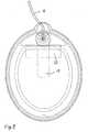
- Fig. 1shows an exploded view of an electrode according to a preferred embodiment of the invention.
- the embodiment shown in Fig. 1includes an electrically insulating backing or substrate 1.
- the substrate 1has an oblong overall shape and an ear 2 attached to the circumference thereof.
- the substrate 1comprises an aperture 3 near the ear 2.
- An electrically conductive layer 4 of tin foilis centred attached to the substrate 1.
- a by-pass element 19is provided, and between the by-pass element and the electrically conductive layer, a shield 20 as an adhesive tape is placed.
- a relief film 5is placed in the area in the vicinity of the point.
- a small hole 14is provided in the relief film, and the electrically conductive layer 4 has a hole 15.
- the by-pass elementcomprises a hole 16.
- a rivet 6is provided and meets the lug 17 to provide an effective electrical contact.
- a wire 18is soldered to the lug 17, and a protective cap 7 is covering the electrically conductive parts.
- a double sided adhesive tape 21is provided at the perimeter area of the electrode and attaches a frame 11 to the electrically insulating backing.
- the area delimited by the frame 11 and a release liner 13is filled with an electrically conductive gel 12.
- the release linerPrior to the use of the skin electrode according to the embodiment shown in Fig. 1, the release liner is removed. Subsequently, the surface of the gel is brought into contact with the skin of a patient. The skin adhering ability of the gel ensures that the electrode remains in position.
- the by-pass element 19 of tinextends from the connection zone to a central area of the electrically conductive layer 4 of tin.
- a shield 20 of a polymeric materialis provided to prevent a possible pitting or etching of the electrically conductive layer 4 to protrude to the by-pass element 19.
Landscapes
- Life Sciences & Earth Sciences (AREA)
- Health & Medical Sciences (AREA)
- Surgery (AREA)
- Biophysics (AREA)
- Pathology (AREA)
- Engineering & Computer Science (AREA)
- Biomedical Technology (AREA)
- Heart & Thoracic Surgery (AREA)
- Medical Informatics (AREA)
- Molecular Biology (AREA)
- Physics & Mathematics (AREA)
- Animal Behavior & Ethology (AREA)
- General Health & Medical Sciences (AREA)
- Public Health (AREA)
- Veterinary Medicine (AREA)
- Chemical & Material Sciences (AREA)
- Dispersion Chemistry (AREA)
- Electrotherapy Devices (AREA)
- Fixed Capacitors And Capacitor Manufacturing Machines (AREA)
- Ceramic Capacitors (AREA)
- Thermistors And Varistors (AREA)
- Measuring And Recording Apparatus For Diagnosis (AREA)
- Prostheses (AREA)
Abstract
Description
Claims (11)
- An electrode for establishing electrical contactwith skin, comprising
an electrically conductive layer (4) provided withmeans for establishing electrical connection to anapparatus for supplying or measuring electrical signals,and
an electrically conductive gel (12) covering apart of a first side of the electrically conductivelayer (4) so that the circumference of the electricallyconductive gel (12) at least partly crosses thesurface of the first side of the electrically conductivelayer(4),
characterized in that
an electrically conductive by-pass element (19)provided with means for establishing electrical connectionto said apparatus for supplying or measuringelectrically signals, on the second side of the electricallyconductive layer (4), is provided so that itextends over at least a part of said second side opposingthe circumference of the gel (12) crossing thesurface of the electrically conductive layer (4) onthe first side and is in electrical contact with thesecond side of the electrically conductive layer (4)at at least one point opposing an area covered withthe electrically conductive gel (12) at the firstside of the electrically conductive layer (4). - An electrode according to claim 1, wherein ashield (20) is provided between the by-pass element(19) and an area of the second side of the electricallyconductive layer (4) opposing at least a partof the circumference of the electrically conductivegel (12) on the first side.
- An electrode according to claim 1 or 2, whereinthe shield (20) is of an insulating, flexible, polymericmaterial.
- An electrode according to any of the precedingclaims, wherein the by-pass element (19) and the electrically conductive layer (4) share common meansfor connection to the apparatus for supplying ormeasuring electrical signals.
- An electrode according to any of the precedingclaims, wherein the electrically conductive layer (4)and/or the by-pass element (19) comprise or comprisesa mixture of a binding agent and particles of a conductingmaterial provided on a suitable carrier.
- An electrode according to claim 5, wherein theparticles of the conducting material is of carbon.
- An electrode according to claim 5, wherein theparticles of the conducting material is a mixture ofparticles of a metal and a salt of said metal.
- An electrode according to claim 7, wherein theelectrically conductive layer (4) comprises Ag andAgCl particles distributed in the binding agent.
- An electrode according to claim 5, wherein thecarrier is an insulating, flexible, polymeric material.
- An electrode according any of the precedentclaims, wherein the electrically conductive layer (4)and/or the by-pass element (19) comprise or comprisestin, aluminium, zinc, silver, lead or any combinationthereof.
- An electrode according to any of the precedingclaims, wherein the electrically conductive gel (12)is acid or alkaline.
Applications Claiming Priority (3)
| Application Number | Priority Date | Filing Date | Title |
|---|---|---|---|
| DKPA200001118 | 2000-07-19 | ||
| DK200001118 | 2000-07-19 | ||
| PCT/DK2001/000483WO2002005712A1 (en) | 2000-07-19 | 2001-07-11 | A skin electrode with a by-pass element |
Publications (2)
| Publication Number | Publication Date |
|---|---|
| EP1301123A1 EP1301123A1 (en) | 2003-04-16 |
| EP1301123B1true EP1301123B1 (en) | 2004-12-08 |
Family
ID=8159622
Family Applications (1)
| Application Number | Title | Priority Date | Filing Date |
|---|---|---|---|
| EP01951451AExpired - LifetimeEP1301123B1 (en) | 2000-07-19 | 2001-07-11 | A skin electrode with a by-pass element |
Country Status (8)
| Country | Link |
|---|---|
| US (1) | US7146228B2 (en) |
| EP (1) | EP1301123B1 (en) |
| AT (1) | ATE284169T1 (en) |
| AU (1) | AU2001272370A1 (en) |
| DE (1) | DE60107685T2 (en) |
| DK (1) | DK1301123T3 (en) |
| ES (1) | ES2233662T3 (en) |
| WO (1) | WO2002005712A1 (en) |
Families Citing this family (71)
| Publication number | Priority date | Publication date | Assignee | Title |
|---|---|---|---|---|
| DK1182966T3 (en) | 1999-05-25 | 2004-04-13 | Medicotest As | Electrode for application to the skin |
| WO2002005712A1 (en) | 2000-07-19 | 2002-01-24 | Medicotest A/S | A skin electrode with a by-pass element |
| US7904180B2 (en)* | 2004-10-04 | 2011-03-08 | Peerlead Medical, Inc. | Capacitive medical electrode |
| USD566847S1 (en)* | 2005-04-22 | 2008-04-15 | Inovise Medical, Inc. | Electrical sensor conductor pattern |
| US8730031B2 (en) | 2005-04-28 | 2014-05-20 | Proteus Digital Health, Inc. | Communication system using an implantable device |
| EP3827747A1 (en) | 2005-04-28 | 2021-06-02 | Otsuka Pharmaceutical Co., Ltd. | Pharma-informatics system |
| US8836513B2 (en) | 2006-04-28 | 2014-09-16 | Proteus Digital Health, Inc. | Communication system incorporated in an ingestible product |
| US9198608B2 (en) | 2005-04-28 | 2015-12-01 | Proteus Digital Health, Inc. | Communication system incorporated in a container |
| US8912908B2 (en) | 2005-04-28 | 2014-12-16 | Proteus Digital Health, Inc. | Communication system with remote activation |
| US8802183B2 (en) | 2005-04-28 | 2014-08-12 | Proteus Digital Health, Inc. | Communication system with enhanced partial power source and method of manufacturing same |
| US8547248B2 (en) | 2005-09-01 | 2013-10-01 | Proteus Digital Health, Inc. | Implantable zero-wire communications system |
| JP2009544338A (en) | 2006-05-02 | 2009-12-17 | プロテウス バイオメディカル インコーポレイテッド | Treatment regimen customized to the patient |
| EP2087589B1 (en) | 2006-10-17 | 2011-11-23 | Proteus Biomedical, Inc. | Low voltage oscillator for medical devices |
| SG175681A1 (en) | 2006-10-25 | 2011-11-28 | Proteus Biomedical Inc | Controlled activation ingestible identifier |
| US8718193B2 (en) | 2006-11-20 | 2014-05-06 | Proteus Digital Health, Inc. | Active signal processing personal health signal receivers |
| CN101686800A (en) | 2007-02-01 | 2010-03-31 | 普罗秋斯生物医学公司 | Ingestible Event Marker System |
| US8956288B2 (en) | 2007-02-14 | 2015-02-17 | Proteus Digital Health, Inc. | In-body power source having high surface area electrode |
| EP2124725A1 (en) | 2007-03-09 | 2009-12-02 | Proteus Biomedical, Inc. | In-body device having a multi-directional transmitter |
| EP2063771A1 (en) | 2007-03-09 | 2009-06-03 | Proteus Biomedical, Inc. | In-body device having a deployable antenna |
| US20080286471A1 (en)* | 2007-05-18 | 2008-11-20 | Doubleday Marc D | Protective gel for an electrical connection |
| US8115618B2 (en) | 2007-05-24 | 2012-02-14 | Proteus Biomedical, Inc. | RFID antenna for in-body device |
| DK2192946T3 (en) | 2007-09-25 | 2022-11-21 | Otsuka Pharma Co Ltd | In-body device with virtual dipole signal amplification |
| CN104376659B (en) | 2008-03-05 | 2019-10-25 | 普罗透斯数字保健公司 | The ingestible event flag of multi-modal communications and system, and the method using it |
| AU2009268827B2 (en) | 2008-07-08 | 2013-10-24 | Proteus Digital Health, Inc. | Ingestible event marker data framework |
| MY154217A (en) | 2008-08-13 | 2015-05-15 | Proteus Digital Health Inc | Ingestible circuitry |
| US8036748B2 (en) | 2008-11-13 | 2011-10-11 | Proteus Biomedical, Inc. | Ingestible therapy activator system and method |
| EP2358270A4 (en) | 2008-12-11 | 2014-08-13 | Proteus Digital Health Inc | Evaluation of gastrointestinal function using portable electroviscerography systems and methods of using the same |
| US9439566B2 (en) | 2008-12-15 | 2016-09-13 | Proteus Digital Health, Inc. | Re-wearable wireless device |
| TWI503101B (en) | 2008-12-15 | 2015-10-11 | Proteus Digital Health Inc | Body-associated receiver and method |
| US9659423B2 (en) | 2008-12-15 | 2017-05-23 | Proteus Digital Health, Inc. | Personal authentication apparatus system and method |
| SG172847A1 (en) | 2009-01-06 | 2011-08-29 | Proteus Biomedical Inc | Pharmaceutical dosages delivery system |
| KR20110103446A (en) | 2009-01-06 | 2011-09-20 | 프로테우스 바이오메디컬, 인코포레이티드 | Intake-Related Biofeedback and Individualized Medical Treatment Methods and Systems |
| WO2010111403A2 (en) | 2009-03-25 | 2010-09-30 | Proteus Biomedical, Inc. | Probablistic pharmacokinetic and pharmacodynamic modeling |
| EP3906845A1 (en) | 2009-04-28 | 2021-11-10 | Otsuka Pharmaceutical Co., Ltd. | Highly reliable ingestible event markers |
| EP2432458A4 (en) | 2009-05-12 | 2014-02-12 | Proteus Digital Health Inc | Ingestible event markers comprising an ingestible component |
| US8558563B2 (en) | 2009-08-21 | 2013-10-15 | Proteus Digital Health, Inc. | Apparatus and method for measuring biochemical parameters |
| TWI517050B (en) | 2009-11-04 | 2016-01-11 | 普羅托斯數位健康公司 | System for supply chain management |
| UA109424C2 (en) | 2009-12-02 | 2015-08-25 | PHARMACEUTICAL PRODUCT, PHARMACEUTICAL TABLE WITH ELECTRONIC MARKER AND METHOD OF MANUFACTURING PHARMACEUTICAL TABLETS | |
| BR112012019212A2 (en) | 2010-02-01 | 2017-06-13 | Proteus Digital Health Inc | data collection system |
| WO2011127252A2 (en) | 2010-04-07 | 2011-10-13 | Proteus Biomedical, Inc. | Miniature ingestible device |
| TWI557672B (en) | 2010-05-19 | 2016-11-11 | 波提亞斯數位康健公司 | Computer system and computer-implemented method to track medication from manufacturer to a patient, apparatus and method for confirming delivery of medication to a patient, patient interface device |
| US11259735B2 (en)* | 2010-05-25 | 2022-03-01 | Neurowave Systems Inc. | Physiological recording device with novel and proprietary connector |
| JP2014504902A (en) | 2010-11-22 | 2014-02-27 | プロテウス デジタル ヘルス, インコーポレイテッド | Ingestible device with medicinal product |
| WO2012125425A2 (en) | 2011-03-11 | 2012-09-20 | Proteus Biomedical, Inc. | Wearable personal body associated device with various physical configurations |
| US9756874B2 (en) | 2011-07-11 | 2017-09-12 | Proteus Digital Health, Inc. | Masticable ingestible product and communication system therefor |
| WO2015112603A1 (en) | 2014-01-21 | 2015-07-30 | Proteus Digital Health, Inc. | Masticable ingestible product and communication system therefor |
| PH12014500174A1 (en) | 2011-07-21 | 2024-02-12 | Proteus Digital Health Inc | Mobile communication device, system, and method |
| US9235683B2 (en) | 2011-11-09 | 2016-01-12 | Proteus Digital Health, Inc. | Apparatus, system, and method for managing adherence to a regimen |
| EP2874886B1 (en) | 2012-07-23 | 2023-12-20 | Otsuka Pharmaceutical Co., Ltd. | Techniques for manufacturing ingestible event markers comprising an ingestible component |
| AU2013331417B2 (en) | 2012-10-18 | 2016-06-02 | Proteus Digital Health, Inc. | Apparatus, system, and method to adaptively optimize power dissipation and broadcast power in a power source for a communication device |
| US9108039B2 (en)* | 2012-11-15 | 2015-08-18 | Zoll Medical Corporation | Electrode construction for crevice corrosion protection |
| US11149123B2 (en) | 2013-01-29 | 2021-10-19 | Otsuka Pharmaceutical Co., Ltd. | Highly-swellable polymeric films and compositions comprising the same |
| JP6498177B2 (en) | 2013-03-15 | 2019-04-10 | プロテウス デジタル ヘルス, インコーポレイテッド | Identity authentication system and method |
| WO2014144738A1 (en) | 2013-03-15 | 2014-09-18 | Proteus Digital Health, Inc. | Metal detector apparatus, system, and method |
| US10314506B2 (en)* | 2013-05-15 | 2019-06-11 | Polar Electro Oy | Heart activity sensor structure |
| USD719267S1 (en)* | 2013-05-21 | 2014-12-09 | Echo Therapeutics, Inc. | Analyte sensor |
| EP3005281A4 (en) | 2013-06-04 | 2017-06-28 | Proteus Digital Health, Inc. | System, apparatus and methods for data collection and assessing outcomes |
| US9796576B2 (en) | 2013-08-30 | 2017-10-24 | Proteus Digital Health, Inc. | Container with electronically controlled interlock |
| CA2965941C (en) | 2013-09-20 | 2020-01-28 | Proteus Digital Health, Inc. | Methods, devices and systems for receiving and decoding a signal in the presence of noise using slices and warping |
| WO2015044722A1 (en) | 2013-09-24 | 2015-04-02 | Proteus Digital Health, Inc. | Method and apparatus for use with received electromagnetic signal at a frequency not known exactly in advance |
| US10084880B2 (en) | 2013-11-04 | 2018-09-25 | Proteus Digital Health, Inc. | Social media networking based on physiologic information |
| EP3164064A1 (en) | 2014-07-03 | 2017-05-10 | Koninklijke Philips N.V. | Medical electrode |
| US11051543B2 (en) | 2015-07-21 | 2021-07-06 | Otsuka Pharmaceutical Co. Ltd. | Alginate on adhesive bilayer laminate film |
| KR20210018961A (en) | 2016-07-22 | 2021-02-18 | 프로테우스 디지털 헬스, 인코포레이티드 | Electromagnetic sensing and detection of ingestible event markers |
| US11464438B2 (en) | 2016-08-11 | 2022-10-11 | Willowwood Global Llc | Conductive human interfaces |
| US11213409B2 (en) | 2016-08-11 | 2022-01-04 | Willowwood Global Llc | Conductive human interfaces |
| WO2018067932A1 (en)* | 2016-10-06 | 2018-04-12 | The Ohio Willow Wood Company | Electrically conductive gel and conductive human interfaces and electrodes formed using electrically conductive gel |
| CN109963499B (en) | 2016-10-26 | 2022-02-25 | 大冢制药株式会社 | Method for manufacturing capsules with ingestible event markers |
| US20190046065A1 (en)* | 2017-08-13 | 2019-02-14 | Aed Pad Llc | Medical Electrode Providing Improved Uniformity of Current Density, Recovery Time and Durability |
| CN112426157B (en)* | 2019-08-09 | 2024-05-31 | 北京海思瑞格科技有限公司 | Electrode paste assembly |
| SE544237C2 (en)* | 2020-03-16 | 2022-03-08 | Piotrode Medical Ab | Shielded body electrode for recording electrophysiological signals from a body providing a contact between the shield and the skin of the body |
Family Cites Families (42)
| Publication number | Priority date | Publication date | Assignee | Title |
|---|---|---|---|---|
| US3993049A (en) | 1974-12-26 | 1976-11-23 | Kater John A R | Electrodes and materials therefor |
| JPS5927940B2 (en)* | 1976-09-14 | 1984-07-09 | キヤノン株式会社 | small calculator |
| DE2727396C3 (en) | 1977-06-18 | 1983-12-08 | Beiersdorf Ag, 2000 Hamburg | Electrically conductive, viscoelastic gel |
| US4352359A (en) | 1977-08-19 | 1982-10-05 | Minnesota Mining And Manufacturing Company | Biomedical electrode |
| DE2737665A1 (en) | 1977-08-20 | 1979-03-01 | Somatron Biofeedback Gmbh | SKIN ELECTRODE FOR ELECTROMEDICAL PURPOSES |
| US4838273A (en) | 1979-04-30 | 1989-06-13 | Baxter International Inc. | Medical electrode |
| US4543958A (en)* | 1979-04-30 | 1985-10-01 | Ndm Corporation | Medical electrode assembly |
| US4300575A (en) | 1979-06-25 | 1981-11-17 | Staodynamics, Inc. | Air-permeable disposable electrode |
| US4365634A (en) | 1979-12-06 | 1982-12-28 | C. R. Bard, Inc. | Medical electrode construction |
| AU543967B2 (en) | 1980-01-23 | 1985-05-09 | Minnesota Mining And Manufacturing Company | Conductive adhesive and biomedical electrode |
| US4539996A (en) | 1980-01-23 | 1985-09-10 | Minnesota Mining And Manufacturing Company | Conductive adhesive and biomedical electrode |
| JPS5933361Y2 (en) | 1980-03-14 | 1984-09-18 | 日東電工株式会社 | electrode pad |
| US4852585A (en) | 1980-08-08 | 1989-08-01 | Darox Corporation | Tin-stannous chloride electrode element |
| US4895169A (en) | 1980-08-08 | 1990-01-23 | Darox Corporation | Disposable non-invasive stimulating electrode set |
| US4834103A (en) | 1980-08-08 | 1989-05-30 | Darox Corporation | Disposable physiological electrode set |
| DE3173905D1 (en) | 1980-11-20 | 1986-04-03 | Crosfield Electronics Ltd | Coating of polymerical substrates |
| US4934383A (en)* | 1982-04-23 | 1990-06-19 | George Glumac | Electrode |
| US4848348A (en) | 1983-11-14 | 1989-07-18 | Minnesota Mining And Manufacturing Company | Coated films |
| US4583551A (en) | 1984-11-19 | 1986-04-22 | Harold Pike | Multipolar medical electrode |
| US4776350A (en) | 1986-01-07 | 1988-10-11 | Physio-Control Corporation | External electrode for heart stimulation and connector therefor |
| US4674512A (en) | 1986-02-03 | 1987-06-23 | Lectec Corporation | Medical electrode for monitoring and diagnostic use |
| US5250022A (en) | 1990-09-25 | 1993-10-05 | Rutgers, The State University Of New Jersey | Iontotherapeutic devices, reservoir electrode devices therefore, process and unit dose |
| US4757817A (en) | 1987-03-09 | 1988-07-19 | Lead-Lok, Inc. | Adhesive electrode pad |
| JPH0436810Y2 (en) | 1987-12-29 | 1992-08-31 | ||
| CA1326063C (en) | 1988-01-04 | 1994-01-11 | David Rolf | Electrode with hydrogel matrix for medical use |
| US4989607A (en) | 1989-03-30 | 1991-02-05 | Preston Keusch | Highly conductive non-stringy adhesive hydrophilic gels and medical electrode assemblies manufactured therefrom |
| EP0429842B1 (en) | 1989-10-27 | 1996-08-28 | Korea Research Institute Of Chemical Technology | Device for the transdermal administration of protein or peptide drug |
| US5203330A (en) | 1991-02-26 | 1993-04-20 | Vickers Plc | Disposable electrodes for electromyography (EMG) and nerve conduction velocity (NCV) and kit containing same |
| US5197472A (en) | 1991-07-26 | 1993-03-30 | Graphic Controls Corporation | Disposable leg plate electrode assembly |
| US5264249A (en) | 1992-03-20 | 1993-11-23 | Medtronic, Inc. | Method for making a conductive coated product |
| US5330526A (en) | 1992-05-01 | 1994-07-19 | Zmd Corporation | Combined defibrillation and pacing electrode |
| USD366317S (en) | 1994-07-18 | 1996-01-16 | Jens Axelgaard | Medical electrode |
| CA2218760A1 (en) | 1996-10-18 | 1998-04-18 | Graphic Controls Corporation | Defibrillator electrode |
| US6019877A (en) | 1998-06-18 | 2000-02-01 | Zmd Corporation | Protecting medical electrodes from corrosion |
| US6280463B1 (en) | 1998-08-26 | 2001-08-28 | Zmd Corporation | Reducing skin damage in use of medical electrodes |
| USD423673S (en) | 1998-09-01 | 2000-04-25 | Medicotest A/S | Electrode for medical use |
| DK1182966T3 (en)* | 1999-05-25 | 2004-04-13 | Medicotest As | Electrode for application to the skin |
| EP1276536B1 (en) | 2000-04-27 | 2004-09-15 | Medicotest A/S | A method for reducing decomposition during storage of a skin electrode |
| EP1284644B1 (en) | 2000-05-29 | 2004-10-20 | Medicotest A/S | An electrode for establishing electrical contact with the skin |
| WO2002005712A1 (en) | 2000-07-19 | 2002-01-24 | Medicotest A/S | A skin electrode with a by-pass element |
| AU2001279588A1 (en) | 2000-07-25 | 2002-02-05 | Medicotest A/S | An electromedical electrode with a snap connecting means |
| USD478173S1 (en) | 2001-10-11 | 2003-08-05 | Medicotest A/S | Electrode |
- 2001
- 2001-07-11WOPCT/DK2001/000483patent/WO2002005712A1/enactiveIP Right Grant
- 2001-07-11DEDE60107685Tpatent/DE60107685T2/ennot_activeExpired - Lifetime
- 2001-07-11USUS10/333,325patent/US7146228B2/ennot_activeExpired - Fee Related
- 2001-07-11DKDK01951451Tpatent/DK1301123T3/enactive
- 2001-07-11AUAU2001272370Apatent/AU2001272370A1/ennot_activeAbandoned
- 2001-07-11EPEP01951451Apatent/EP1301123B1/ennot_activeExpired - Lifetime
- 2001-07-11ATAT01951451Tpatent/ATE284169T1/enactive
- 2001-07-11ESES01951451Tpatent/ES2233662T3/ennot_activeExpired - Lifetime
Also Published As
| Publication number | Publication date |
|---|---|
| EP1301123A1 (en) | 2003-04-16 |
| DE60107685D1 (en) | 2005-01-13 |
| DE60107685T2 (en) | 2005-10-06 |
| DK1301123T3 (en) | 2005-01-24 |
| US7146228B2 (en) | 2006-12-05 |
| WO2002005712A1 (en) | 2002-01-24 |
| US20040015222A1 (en) | 2004-01-22 |
| ES2233662T3 (en) | 2005-06-16 |
| ATE284169T1 (en) | 2004-12-15 |
| AU2001272370A1 (en) | 2002-01-30 |
Similar Documents
| Publication | Publication Date | Title |
|---|---|---|
| EP1301123B1 (en) | A skin electrode with a by-pass element | |
| EP1284644B1 (en) | An electrode for establishing electrical contact with the skin | |
| EP1182966B1 (en) | A skin electrode | |
| CN1114452C (en) | Multifunctional Biomedical Electrodes | |
| CA2479378C (en) | Wireless electrode having activatable power cell | |
| US5195523A (en) | Medical electrode assembly | |
| EP2226094B1 (en) | Novel electrodes | |
| MX2007012154A (en) | Medical electrode. | |
| JPH10507651A (en) | Electrodes with vents | |
| JPH0341190B2 (en) | ||
| US4832036A (en) | Medical electrode | |
| US6898465B2 (en) | Differential gel body for a medical stimulation electrode | |
| US20190046065A1 (en) | Medical Electrode Providing Improved Uniformity of Current Density, Recovery Time and Durability | |
| EP1412020B1 (en) | Corrosion prevention in biomedical electrodes | |
| EP1276536B1 (en) | A method for reducing decomposition during storage of a skin electrode | |
| EP4344639A1 (en) | Silver/silver chloride sensor element | |
| ES2214030T3 (en) | AN ELECTRODE FOR SKIN. | |
| JP2584674Y2 (en) | Bioelectrode structure with snap |
Legal Events
| Date | Code | Title | Description |
|---|---|---|---|
| PUAI | Public reference made under article 153(3) epc to a published international application that has entered the european phase | Free format text:ORIGINAL CODE: 0009012 | |
| 17P | Request for examination filed | Effective date:20030210 | |
| AK | Designated contracting states | Designated state(s):AT BE CH CY DE DK ES FI FR GB GR IE IT LI LU MC NL PT SE TR | |
| AX | Request for extension of the european patent | Extension state:AL LT LV MK RO SI | |
| RIN1 | Information on inventor provided before grant (corrected) | Inventor name:NIELSEN, BRIAN | |
| GRAP | Despatch of communication of intention to grant a patent | Free format text:ORIGINAL CODE: EPIDOSNIGR1 | |
| GRAS | Grant fee paid | Free format text:ORIGINAL CODE: EPIDOSNIGR3 | |
| GRAA | (expected) grant | Free format text:ORIGINAL CODE: 0009210 | |
| RAP1 | Party data changed (applicant data changed or rights of an application transferred) | Owner name:MEDICOTEST A/S | |
| AK | Designated contracting states | Kind code of ref document:B1 Designated state(s):AT BE CH CY DE DK ES FI FR GB GR IE IT LI LU MC NL PT SE TR | |
| PG25 | Lapsed in a contracting state [announced via postgrant information from national office to epo] | Ref country code:TR Free format text:LAPSE BECAUSE OF FAILURE TO SUBMIT A TRANSLATION OF THE DESCRIPTION OR TO PAY THE FEE WITHIN THE PRESCRIBED TIME-LIMIT Effective date:20041208 Ref country code:CH Free format text:LAPSE BECAUSE OF FAILURE TO SUBMIT A TRANSLATION OF THE DESCRIPTION OR TO PAY THE FEE WITHIN THE PRESCRIBED TIME-LIMIT Effective date:20041208 Ref country code:FI Free format text:LAPSE BECAUSE OF FAILURE TO SUBMIT A TRANSLATION OF THE DESCRIPTION OR TO PAY THE FEE WITHIN THE PRESCRIBED TIME-LIMIT Effective date:20041208 Ref country code:LI Free format text:LAPSE BECAUSE OF FAILURE TO SUBMIT A TRANSLATION OF THE DESCRIPTION OR TO PAY THE FEE WITHIN THE PRESCRIBED TIME-LIMIT Effective date:20041208 Ref country code:BE Free format text:LAPSE BECAUSE OF FAILURE TO SUBMIT A TRANSLATION OF THE DESCRIPTION OR TO PAY THE FEE WITHIN THE PRESCRIBED TIME-LIMIT Effective date:20041208 Ref country code:NL Free format text:LAPSE BECAUSE OF FAILURE TO SUBMIT A TRANSLATION OF THE DESCRIPTION OR TO PAY THE FEE WITHIN THE PRESCRIBED TIME-LIMIT Effective date:20041208 | |
| REG | Reference to a national code | Ref country code:GB Ref legal event code:FG4D | |
| REG | Reference to a national code | Ref country code:CH Ref legal event code:EP | |
| REG | Reference to a national code | Ref country code:IE Ref legal event code:FG4D | |
| REF | Corresponds to: | Ref document number:60107685 Country of ref document:DE Date of ref document:20050113 Kind code of ref document:P | |
| REG | Reference to a national code | Ref country code:DK Ref legal event code:T3 | |
| PG25 | Lapsed in a contracting state [announced via postgrant information from national office to epo] | Ref country code:GR Free format text:LAPSE BECAUSE OF FAILURE TO SUBMIT A TRANSLATION OF THE DESCRIPTION OR TO PAY THE FEE WITHIN THE PRESCRIBED TIME-LIMIT Effective date:20050308 Ref country code:SE Free format text:LAPSE BECAUSE OF FAILURE TO SUBMIT A TRANSLATION OF THE DESCRIPTION OR TO PAY THE FEE WITHIN THE PRESCRIBED TIME-LIMIT Effective date:20050308 | |
| NLV1 | Nl: lapsed or annulled due to failure to fulfill the requirements of art. 29p and 29m of the patents act | ||
| REG | Reference to a national code | Ref country code:CH Ref legal event code:PL | |
| REG | Reference to a national code | Ref country code:ES Ref legal event code:FG2A Ref document number:2233662 Country of ref document:ES Kind code of ref document:T3 | |
| PG25 | Lapsed in a contracting state [announced via postgrant information from national office to epo] | Ref country code:CY Free format text:LAPSE BECAUSE OF FAILURE TO SUBMIT A TRANSLATION OF THE DESCRIPTION OR TO PAY THE FEE WITHIN THE PRESCRIBED TIME-LIMIT Effective date:20050711 Ref country code:IE Free format text:LAPSE BECAUSE OF NON-PAYMENT OF DUE FEES Effective date:20050711 Ref country code:LU Free format text:LAPSE BECAUSE OF NON-PAYMENT OF DUE FEES Effective date:20050711 | |
| PG25 | Lapsed in a contracting state [announced via postgrant information from national office to epo] | Ref country code:MC Free format text:LAPSE BECAUSE OF NON-PAYMENT OF DUE FEES Effective date:20050731 | |
| PLBE | No opposition filed within time limit | Free format text:ORIGINAL CODE: 0009261 | |
| STAA | Information on the status of an ep patent application or granted ep patent | Free format text:STATUS: NO OPPOSITION FILED WITHIN TIME LIMIT | |
| ET | Fr: translation filed | ||
| 26N | No opposition filed | Effective date:20050909 | |
| REG | Reference to a national code | Ref country code:IE Ref legal event code:MM4A | |
| PG25 | Lapsed in a contracting state [announced via postgrant information from national office to epo] | Ref country code:PT Free format text:LAPSE BECAUSE OF NON-PAYMENT OF DUE FEES Effective date:20050508 | |
| PGFP | Annual fee paid to national office [announced via postgrant information from national office to epo] | Ref country code:AT Payment date:20110726 Year of fee payment:11 | |
| PGFP | Annual fee paid to national office [announced via postgrant information from national office to epo] | Ref country code:IT Payment date:20110729 Year of fee payment:11 | |
| REG | Reference to a national code | Ref country code:AT Ref legal event code:MM01 Ref document number:284169 Country of ref document:AT Kind code of ref document:T Effective date:20120711 | |
| PG25 | Lapsed in a contracting state [announced via postgrant information from national office to epo] | Ref country code:IT Free format text:LAPSE BECAUSE OF NON-PAYMENT OF DUE FEES Effective date:20120711 | |
| PG25 | Lapsed in a contracting state [announced via postgrant information from national office to epo] | Ref country code:AT Free format text:LAPSE BECAUSE OF NON-PAYMENT OF DUE FEES Effective date:20120711 | |
| PGFP | Annual fee paid to national office [announced via postgrant information from national office to epo] | Ref country code:DK Payment date:20130716 Year of fee payment:13 Ref country code:DE Payment date:20130716 Year of fee payment:13 Ref country code:ES Payment date:20130710 Year of fee payment:13 | |
| PGFP | Annual fee paid to national office [announced via postgrant information from national office to epo] | Ref country code:GB Payment date:20130708 Year of fee payment:13 Ref country code:FR Payment date:20130725 Year of fee payment:13 | |
| REG | Reference to a national code | Ref country code:DE Ref legal event code:R119 Ref document number:60107685 Country of ref document:DE | |
| REG | Reference to a national code | Ref country code:DK Ref legal event code:EBP Effective date:20140731 | |
| GBPC | Gb: european patent ceased through non-payment of renewal fee | Effective date:20140711 | |
| REG | Reference to a national code | Ref country code:FR Ref legal event code:ST Effective date:20150331 | |
| PG25 | Lapsed in a contracting state [announced via postgrant information from national office to epo] | Ref country code:DE Free format text:LAPSE BECAUSE OF NON-PAYMENT OF DUE FEES Effective date:20150203 | |
| REG | Reference to a national code | Ref country code:DE Ref legal event code:R119 Ref document number:60107685 Country of ref document:DE Effective date:20150203 | |
| PG25 | Lapsed in a contracting state [announced via postgrant information from national office to epo] | Ref country code:GB Free format text:LAPSE BECAUSE OF NON-PAYMENT OF DUE FEES Effective date:20140711 Ref country code:FR Free format text:LAPSE BECAUSE OF NON-PAYMENT OF DUE FEES Effective date:20140731 | |
| PG25 | Lapsed in a contracting state [announced via postgrant information from national office to epo] | Ref country code:DK Free format text:LAPSE BECAUSE OF NON-PAYMENT OF DUE FEES Effective date:20140731 | |
| REG | Reference to a national code | Ref country code:ES Ref legal event code:FD2A Effective date:20150828 | |
| PG25 | Lapsed in a contracting state [announced via postgrant information from national office to epo] | Ref country code:ES Free format text:LAPSE BECAUSE OF NON-PAYMENT OF DUE FEES Effective date:20140712 |