EP1297643B1 - Geolocation techniques for an airborne cellular system - Google Patents
Geolocation techniques for an airborne cellular systemDownload PDFInfo
- Publication number
- EP1297643B1 EP1297643B1EP01950636AEP01950636AEP1297643B1EP 1297643 B1EP1297643 B1EP 1297643B1EP 01950636 AEP01950636 AEP 01950636AEP 01950636 AEP01950636 AEP 01950636AEP 1297643 B1EP1297643 B1EP 1297643B1
- Authority
- EP
- European Patent Office
- Prior art keywords
- location
- airplane
- billing
- repeater
- geographic
- Prior art date
- Legal status (The legal status is an assumption and is not a legal conclusion. Google has not performed a legal analysis and makes no representation as to the accuracy of the status listed.)
- Expired - Lifetime
Links
- 238000000034methodMethods0.000titleclaimsabstractdescription30
- 230000001413cellular effectEffects0.000titledescription32
- 230000010267cellular communicationEffects0.000claimsabstractdescription16
- 238000013507mappingMethods0.000claimsabstract4
- 238000005259measurementMethods0.000claimsdescription11
- 239000004165Methyl ester of fatty acidsSubstances0.000abstractdescription4
- 238000004891communicationMethods0.000description7
- 238000010586diagramMethods0.000description7
- 238000013461designMethods0.000description2
- 230000000977initiatory effectEffects0.000description2
- 238000012545processingMethods0.000description2
- 230000011664signalingEffects0.000description2
- RZVHIXYEVGDQDX-UHFFFAOYSA-N9,10-anthraquinoneChemical compoundC1=CC=C2C(=O)C3=CC=CC=C3C(=O)C2=C1RZVHIXYEVGDQDX-UHFFFAOYSA-N0.000description1
- 230000005540biological transmissionEffects0.000description1
- 239000000969carrierSubstances0.000description1
- 238000012544monitoring processMethods0.000description1
- 230000011218segmentationEffects0.000description1
- 238000001228spectrumMethods0.000description1
- 238000012876topographyMethods0.000description1
Images


Classifications
- H—ELECTRICITY
- H04—ELECTRIC COMMUNICATION TECHNIQUE
- H04B—TRANSMISSION
- H04B7/00—Radio transmission systems, i.e. using radiation field
- H04B7/14—Relay systems
- H04B7/15—Active relay systems
- H04B7/185—Space-based or airborne stations; Stations for satellite systems
- H04B7/18502—Airborne stations
- H04B7/18504—Aircraft used as relay or high altitude atmospheric platform
Definitions
- the present inventionrelates generally to a cellular communications system including an airborne repeater, and particularly to techniques for locating system users within the system coverage area.
- the buildout rate for the terrestrial cell stationsis typically slow and expensive, especially in mountainous or otherwise difficult to access areas.
- a carrier's return on investmentmay not provide the incentive necessary for the carrier to build the necessary cell stations, thereby leaving these areas with either limited or no cellular service at all.
- many areas having a sufficient number of cellular communications base transceiving stations to handle calls during both off-peak and peak timescannot adequately handle large volumes of calls during sporting events or other short-term special events that temporarily attract large crowds.
- airborne cellular systemshave been proposed in which a cellular repeater mounted in an airplane flying a predetermined flight pattern over a geographic area requiring cellular coverage links calls from cellular phones within the covered geographic area to a terrestrial base station. Because the airplane is capable of traversing geographic limitations and takes the place of the cell stations, such a system overcomes the above-mentioned limitations of conventional terrestrial cellular systems.
- U.S. patent no. 6,061,562describes a communication system that includes an aircraft supporting an airborne switching node that provides communicatoin services to a variety of ground-based devices located in the service region.
- the devicesinclude subscriber devices, such as customer premises equipment and business premises equipment, as well as gateway devices.
- an airborne cellular systempresents design and implementation problems not present in the design and implementation of conventional terrestrial cellular systems.
- service providersmust be capable of accurately determining geographic locations of subscribers or roamers within their service areas for billing purposes, for example.
- real-time user locationwill be particularly important in next generation (2.5 - 3G) systems where data and multi-media services will be prevalent. Advertising will be a key operator revenue stream and location-based services/advertising will be premium.
- cell sites in conventional terrestrial cellular communications systemshave very limited propagation ranges, subscriber and roamer locations can be determined rather easily with an accuracy corresponding to the limited ranges of the cell sites.
- FIG. 1shows an airborne cellular communications system 10.
- the system 10generally includes three primary segments: a cellular infrastructure segment 12, a radio infrastructure segment 14, and an airplane segment 16. These three segments in combination are capable of providing cellular communications coverage to a large geographical area by enabling system users, represented generally by handsets 18, to link to a public switched telephone network (PSTN) 20 via an airplane payload 22 including a repeater.
- PSTNpublic switched telephone network
- the cellular infrastructure segment 12includes a mobile switching office (MSO) 24 that includes equipment, such as a telephony switch, voicemail and message service centers, and other conventional components necessary for cellular service.
- MSOmobile switching office
- the MSO 24connects to the PSTN 20 to send and receive telephone calls in a manner well known in the industry.
- OMCoperations and maintenance center
- the MSO 24is also connected to one or more base transceiver stations (BTSs) such as the BTSs shown at 30a, 30b.
- BTSsbase transceiver stations
- the BTSs 30a, 30btransmit and receive RF signals to and from the system users 18 through the radio infrastructure segment 14.
- the BTS 30transmits and receives RF signals through ground converter equipment 32.
- the ground converter equipment 32converts terrestrial cellular format signals to C-band format signals and communicates with the airborne payload 22 through a feeder link 33 and a telemetry link 34, each of which will be discussed later in detail.
- the payload 22establishes a radio link 36 for connecting calls over a wide geographic area of coverage, or footprint, that is capable of exceeding 350 km when the airplane maintains a flight pattern at or around 30,000 feet above the ground.
- the airplane segment 16also includes an airplane operations center 37 that controls mission logistics based at least in part on information from sources such as a weather center 38, and manages all system airplanes, as the system preferably includes three airplanes to ensure continuous coverage (one operational, on en route, as required, and one ground spare).
- the airplanealso receives additional routine instructions from sources such as an air traffic control center 40.
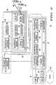
- FIG. 2shows certain components of the system 10 in more detail.
- the ground converter equipment 32includes a C-band antenna 42 for receiving/transmitting signals from/to the payload 22 (a second antenna is also provided for redundancy and plane handoff purposes), and a C-band converter 44 for appropriately converting the signals received from or to be transmitted to the payload 22.
- the C-band antenna 42 and the converter 44enable 800 MHz airborne cellular antennas 56 to communicate with the BTSs 30a, 30b via an established downlink, or feeder link, 33, and the converter 44 upconverts nominal signals from the BTSs 30a, 30b to C-band signals before the signals are transmitted to the airplane 35.
- each sector of each BTS 30a, 30bis assigned a different band in the C-band spectrum so that signals from the different BTSs 30a, 30b can be separated and routed to the correct antenna, such as the antenna 56, at the payload 22.
- the ground control equipment 32includes telemetry components such as a telemetry antenna 46, a telemetry modem 48 and a telemetry processor 50 to receive and process airplane and payload data transmitted from an airplane telemetry antenna 52, while a control terminal 54 controls transmission of the processed telemetry data to the OMC 26 and the airplane operations center 37.
- the airplane telemetry antenna 52 mentioned abovetransmits airplane avionics data generated by airplane avionics equipment, represented generally at 58, including airplane location, direction and flight pattern data as well as other data such as airplane pitch, roll and yaw data.
- the data from the airplane avionics equipment 58is input into and processed by a payload processor 60 before being output to the telemetry antenna 52 through a telemetry modem 62.
- the payload processor 60is also responsible for processing signals transmitted to and received from the ground converter equipment 32 through the feeder link 33 established between the C-band antennas 42, 56 and for processing signals transmitted to and received from the system users 18 through a downlink, or user link, 69 established between the users 18 and a payload downlink antenna such as an 800 MHz antenna 70, with the signals received by and transmitted from the payload being appropriately upconverted or downconverted by an 800 MHz converter 72.
- the components shown in the airplane and in the payloadtogether form the airplane repeater that enables cellular coverage to be provided to a ubiquitous large geographic area that may otherwise not support terrestrial cellular coverage because of an insufficient number of cell stations or the like (often driven by economics or topography).
- both the airborne cellular system 10 and conventional terrestrial cellular systemsappear identical to the PSTN 20 and the system users 18.
- the cellular infrastructure segment 12includes a standard telephony switch in the MSO 24 and BTSs 30a, 30b that are identical or nearly identical to those included in a conventional terrestrial system infrastructure.
- the system 10is designed to meet the performance requirements of standard handsets such as those shown at 18.
- the airplane 35when on-station preferably flies in a circular or near circular flight pattern (although the flight pattern may vary according to specific weather and coverage conditions) to provide coverage to a predetermined geographic area during a mission. While it is on-station, the airplane maintains contact with the ground converter equipment 32 to provide both the feeder link 33 and the user link 36 for the cellular infrastructure segment 12 through the radio infrastructure equipment segment 14.
- the airplane 35also transmits a predetermined number of communications beams, such as, for example, 13 beams, over the coverage area, with each beam being assigned to a sector of one of the BTSs 30a, 30b and having its own set of control and traffic channels to carry signaling and voice data between the system users 18 and the cellular infrastructure segment 12.
- a predetermined number of communications beamssuch as, for example, 13 beams
- each beambeing assigned to a sector of one of the BTSs 30a, 30b and having its own set of control and traffic channels to carry signaling and voice data between the system users 18 and the cellular infrastructure segment 12.
- the beams radiated from the airplanerotate. Therefore, as the system users 18 will "see" a different beam every 45 seconds or so, the cellular infrastructure segment 12 performs a sector to sector handoff of the call to keep the call from being dropped.
- a system userWhen initiating a call, a system user, such as one of the users 18, utilizes the control channels in the beam to signal the MSO 24 to request a call setup.
- the requestis sent from a handset of the user 18 to the airplane payload 22, and then is relayed to the ground converter equipment 32.
- the ground converter equipment 32relays the request to the corresponding BTS, such as the BTS 30a.
- the BTS 30athen transmits the request to the MSO 24, which sets up the call with the PSTN 20.
- the payload 22therefore simply extends the physical layer of the BTS 30 to the users 18 to allow a much wider area of coverage than would typically be provided by a conventional terrestrial system, and with less associated infrastructure buildout cost.
- the airborne system 10is also preferable for providing temporary cellular coverage for special events areas, where coverage is only needed for several days, thereby eliminating the need and cost associated with erecting cell stations and then tearing the cell stations down after the special events end.
- voice communication with the PSTN 20 through the traffic channels in the beamis initiated, and voice information is then relayed in the same manner as the signaling information.
- voice informationis then relayed in the same manner as the signaling information.
- a signalis sent to the MSO 24 to tear down the call, the handset of the user 18 releases the traffic channel used for voice communications, and the channel is returned to an idle state.
- FIG. 3shows certain of the components of a system 10, including an additional BTS 30c not previously shown in FIGs. 1 and 2 (any number of BTSs necessary for implementing the airborne cellular system may be included).
- the components of the system 10are necessary to implement system user location techniques of first and second embodiments in accordance with the present invention that enable an airborne cellular communications service provider to accurately bill system users and roamers based on their location within the system.
- each of the sectors of the respective BTSs 30a-30cis dedicated to a unique one of the exemplary beams having associated beam numbers f 1 , f 2 , f 3 in a beam pattern 80 that is transmitted from the antenna 70 shown in FIG. 2 to the location of active users and that forms the user link 69.
- Beam number information for each beamis transmitted from the airplane 35 to the ground converter equipment 32 through the feeder link 33.
- the ground converter equipment 32upon receiving the beam number information, then creates a pseudo-BTS reference number for each of the beams, and transmits the pseudo-BTS reference numbers to the switch located in the MSO 24.
- a home location register (HLR) and a visited location register (VLR) in the switchthen compare the reference numbers to a list of locations used in a system billing program, and will interpret the reference numbers as though the numbers were BTSs in a conventional terrestrial cellular communications system.
- HLRhome location register
- VLRvisited location register
- a callis initiated in one of the BTSs, such as the BTS 30a.
- airplane location and heading datais transmitted from the airplane avionics equipment 58 shown in FIG. 2 via the telemetry link 34 to the MSO 24, where it is used at 94 to calculate a current beam center location.
- the HLR and VLR in the switchthen compare the calculated beam center location against a list of billing program reference locations to map the calculated beam center location to a closest one of the billing program reference locations.
- the closest one of the billing program reference locationsis then utilized by the MSC 24 as the system user's current location for the purpose of billing the user at a rate that is commensurate with the user's location.
- a system user location methodologythat is more refined than that shown in FIG. 4 and as summarized by the flow diagram in FIG. 5 may be utilized.
- a callis initiated in one of the BTSs, such as the BTS 30a.
- the switchdetermines the current handset location by calculating the user's radial distance in the beam using a time delay algorithm programmed into the MSC 24.
- the time delayis measured by the BTS either via a measurement of the code offset (CDMA) or frame delay (TDMA) and then converted to a radial distance based on the airplane geometry with respect to the ground converter equipment 32.
- CDMAcode offset
- TDMAframe delay
- the HLR and VLRcompare the handset location against a list of billing program reference locations to map the handset location to one of the billing program reference locations.
- the billing program reference locationis then utilized by the MSC 24 to bill the user at a rate that is commensurate with the user's location within the particular beam.
- the system user location techniquesgive a service provider the ability to perform location billing for a cellular communications network including both airborne and terrestrial components.
- the techniquesenable the service provider to generate additional revenue, as system user locations can be more accurately determined and more appropriate billing rates applied, particularly to subscribers of adjacent systems that roam into the coverage area of the system 10.
- the beam pattern 80 transmitted from the antenna 70results in numerous beams, such as the 18 beams shown generally at 108 that together define a beam pattern footprint that covers a predetermined geographic area that may be, for example, 110 km in diameter when the airplane transmits the beam pattern from an elevation of 30,000 feet.
- the beamsrotate as the airplane executes its circular flight pattern.
- the link 36remains stationary relative to the system users due to a series of handoffs that occur between, for example, a beam rotating out of a coverage area and a beam rotating into the same coverage area.
- the radial location of a system user 18 located within a footprint 112 of a beamcan be determined using the above-discussed time delay algorithm as the airplane 35 executes its flight pattern in the direction indicated by the direction arrow A and as represented by the azimuthal angle ⁇ .
- the uncertainty associated with the system user's azimuthal location within the beam f 2can be reduced by a factor of 100 compared to the system user location technique described above in connection with the second embodiment by utilizing beam hand-off information to determine the exact azimuthal location of the system user within a particular beam.
- the system user 18is shown between projections 116, 118 of two beams, such as beams f 1 , f 2 as the beam f 1 forming the footprint 116 rotates out of a coverage area of the user 18 and as the beam f 2 forming the footprint 118 rotates into the coverage area.
- the switchcan determine the system user's azimuthal position within the beam f 1 at the time of handoff, as hand-off information indicating the exact point in time at which the hand-off occurs can be transmitted to the switch in the MSC 24 from the BTS and compared to a database of stored system user azimuthal billing locations, represented by the generally vertical lines within the beam footprint 116, to determine the nearest azimuthal billing location to the calculated location.
- the handoff timeis then converted to an azimuthal location by utilizing the current location and heading of the airplane.
- a service providermay initially assign a less expensive rate to a system user's call until the exact location of the system user can be determined after the subsequent beam hand-off occurs 45 seconds later.
- the system user location technique of the third embodimentis not applicable to a system center beam that potentially does not hand off calls.
- location within the center beamcan be refined using standard triangulation techniques utilizing movement of the airplane to provide spatial diversity.
- Three different measurements separated in timewill each have different ground station, airplane and handset geometry, thereby allowing for triangulation measurement of user location.
- three time-separated measurementswill appear as three location-separated measurements as the airplane continues to execute its flight pattern.
- Two of the measurementswill isolate the user location to two points within the beam.
- the third measurementbreaks the left/right ambiguity created by the first two measurements (unless the third measurement lies on a line connecting the first two measurement points). Therefore, geolocation of a user within a center beam may also be realized.
- the system user location techniques of the embodiments in accordance with the present inventionenable a system user's location within a particular communications beam to be determined with an accuracy that can be refined to a point determined by specific system billing requirements.
- the third embodimentenables a system user's location to be accurately determined based on both its radial and azimuthal location within a specific beam. Such accuracy enables an airborne cellular communications system such as the system 10 to comply with a recent FCC E911 mandate requiring cellular systems to provide a user's location within a 125-meter radius 67% of the time.
Landscapes
- Engineering & Computer Science (AREA)
- Physics & Mathematics (AREA)
- Astronomy & Astrophysics (AREA)
- Aviation & Aerospace Engineering (AREA)
- General Physics & Mathematics (AREA)
- Computer Networks & Wireless Communication (AREA)
- Signal Processing (AREA)
- Mobile Radio Communication Systems (AREA)
- Silicates, Zeolites, And Molecular Sieves (AREA)
- Meter Arrangements (AREA)
- Input Circuits Of Receivers And Coupling Of Receivers And Audio Equipment (AREA)
- Processing Or Creating Images (AREA)
Abstract
Description
Claims (7)
- A method of locating a billing area for a call initiated by a system user (18) inan airborne cellular communications system (10) having an airplane (35) carrying a repeater ofthe airborne cellular communications system (10), comprising:receiving airplane information from the airplane (35);determining a repeater beam location in which coverage was initiated by the systemuser (18) based at least in part on the airplane information from the airplane (35);mapping the repeater beam location to a corresponding geographic billing location; andassociating the call with the corresponding geographic billing location.
- The method of claim 1, wherein the airplane information is a location andheading of the airplane (35) carrying the repeater and the repeater beam location is the centerlocation of the repeater beam.
- The method of claim 1, wherein said airplane information is propagation delayand geometry of the airplane (35) and said repeater beam location is a current handset radialbeam location.
- The method of claim 2, wherein the mapping of the center location comprisescomparing the center location against a list of stored reference locations used by a billingprogram.
- The method of claim 2, wherein the determining of the center location of saidrepeater beam comprises determining a number associated with the beam that is unique to aspecific terrestrial base transceiving station sector; and
using the beam number to create a pseudo-base transceiving station for a terrestrialinfrastructure (12) to enable infrastructure components to interpret beam information asoriginating from a terrestrial base transceiving station. - The method of claim 3, further comprising using a triangulation techniqueutilizing system ground station (12), airplane (35) and handset (18) geometries determined atthree different measurement times if a billing area is located in a central system location.
- The method of claim 3, further comprising determining azimuthal positionwithin a beam footprint by determining a handoff location of a signal from a first beam to asecond beam; and
mapping the handoff location to a closest corresponding azimuthal geographic billinglocation; and
using both the closest corresponding radial and azimuthal geographic billing locationsto identify a current handset location.
Priority Applications (1)
| Application Number | Priority Date | Filing Date | Title |
|---|---|---|---|
| EP04102041AEP1465357B1 (en) | 2000-06-27 | 2001-06-27 | Geolocation techniques for an airborne cellular system |
Applications Claiming Priority (3)
| Application Number | Priority Date | Filing Date | Title |
|---|---|---|---|
| US604634 | 2000-06-27 | ||
| US09/604,634US6795699B1 (en) | 2000-06-27 | 2000-06-27 | Geolocation techniques for an airborne cellular system |
| PCT/US2001/020691WO2002001757A1 (en) | 2000-06-27 | 2001-06-27 | Geolocation techniques for an airborne cellular system |
Related Child Applications (1)
| Application Number | Title | Priority Date | Filing Date |
|---|---|---|---|
| EP04102041ADivisionEP1465357B1 (en) | 2000-06-27 | 2001-06-27 | Geolocation techniques for an airborne cellular system |
Publications (2)
| Publication Number | Publication Date |
|---|---|
| EP1297643A1 EP1297643A1 (en) | 2003-04-02 |
| EP1297643B1true EP1297643B1 (en) | 2004-09-15 |
Family
ID=24420390
Family Applications (2)
| Application Number | Title | Priority Date | Filing Date |
|---|---|---|---|
| EP01950636AExpired - LifetimeEP1297643B1 (en) | 2000-06-27 | 2001-06-27 | Geolocation techniques for an airborne cellular system |
| EP04102041AExpired - LifetimeEP1465357B1 (en) | 2000-06-27 | 2001-06-27 | Geolocation techniques for an airborne cellular system |
Family Applications After (1)
| Application Number | Title | Priority Date | Filing Date |
|---|---|---|---|
| EP04102041AExpired - LifetimeEP1465357B1 (en) | 2000-06-27 | 2001-06-27 | Geolocation techniques for an airborne cellular system |
Country Status (9)
| Country | Link |
|---|---|
| US (1) | US6795699B1 (en) |
| EP (2) | EP1297643B1 (en) |
| AT (2) | ATE336833T1 (en) |
| AU (1) | AU2001271606A1 (en) |
| BR (1) | BR0112183A (en) |
| CA (1) | CA2413430A1 (en) |
| DE (2) | DE60122394T2 (en) |
| MX (1) | MXPA02012797A (en) |
| WO (1) | WO2002001757A1 (en) |
Families Citing this family (86)
| Publication number | Priority date | Publication date | Assignee | Title |
|---|---|---|---|---|
| US8352400B2 (en) | 1991-12-23 | 2013-01-08 | Hoffberg Steven M | Adaptive pattern recognition based controller apparatus and method and human-factored interface therefore |
| US10361802B1 (en) | 1999-02-01 | 2019-07-23 | Blanding Hovenweep, Llc | Adaptive pattern recognition based control system and method |
| US7904187B2 (en)* | 1999-02-01 | 2011-03-08 | Hoffberg Steven M | Internet appliance system and method |
| US6947980B1 (en)* | 2000-08-28 | 2005-09-20 | Qwest Communications International, Inc. | Method and system for verifying modem status |
| US6985942B2 (en)* | 2001-08-23 | 2006-01-10 | The Boeing Company | Airborne IP address structure |
| US8290505B2 (en) | 2006-08-29 | 2012-10-16 | Telecommunications Systems, Inc. | Consequential location derived information |
| US8126889B2 (en) | 2002-03-28 | 2012-02-28 | Telecommunication Systems, Inc. | Location fidelity adjustment based on mobile subscriber privacy profile |
| US9154906B2 (en) | 2002-03-28 | 2015-10-06 | Telecommunication Systems, Inc. | Area watcher for wireless network |
| US8918073B2 (en) | 2002-03-28 | 2014-12-23 | Telecommunication Systems, Inc. | Wireless telecommunications location based services scheme selection |
| US7426380B2 (en) | 2002-03-28 | 2008-09-16 | Telecommunication Systems, Inc. | Location derived presence information |
| US8027697B2 (en) | 2007-09-28 | 2011-09-27 | Telecommunication Systems, Inc. | Public safety access point (PSAP) selection for E911 wireless callers in a GSM type system |
| US6785559B1 (en)* | 2002-06-28 | 2004-08-31 | Interdigital Technology Corporation | System for efficiently covering a sectorized cell utilizing beam forming and sweeping |
| US7043274B2 (en)* | 2002-06-28 | 2006-05-09 | Interdigital Technology Corporation | System for efficiently providing coverage of a sectorized cell for common and dedicated channels utilizing beam forming and sweeping |
| US7546084B2 (en)* | 2002-10-16 | 2009-06-09 | Andrew Llc | System and method of operation for network overlay geolocation system with repeaters |
| US7359700B2 (en)* | 2003-04-02 | 2008-04-15 | The Boeing Coompany | Platform-associated visitor location registers (VLR) for cellular communications |
| US7558569B2 (en)* | 2003-04-02 | 2009-07-07 | The Boeing Company | Induced cellular communications handover |
| US7715838B2 (en)* | 2003-04-02 | 2010-05-11 | The Boeing Company | Aircraft based cellular system |
| US7424293B2 (en) | 2003-12-02 | 2008-09-09 | Telecommunication Systems, Inc. | User plane location based service using message tunneling to support roaming |
| US7260186B2 (en) | 2004-03-23 | 2007-08-21 | Telecommunication Systems, Inc. | Solutions for voice over internet protocol (VoIP) 911 location services |
| US20080090546A1 (en) | 2006-10-17 | 2008-04-17 | Richard Dickinson | Enhanced E911 network access for a call center using session initiation protocol (SIP) messaging |
| US20080126535A1 (en) | 2006-11-28 | 2008-05-29 | Yinjun Zhu | User plane location services over session initiation protocol (SIP) |
| US7629926B2 (en) | 2004-10-15 | 2009-12-08 | Telecommunication Systems, Inc. | Culled satellite ephemeris information for quick, accurate assisted locating satellite location determination for cell site antennas |
| US7411546B2 (en) | 2004-10-15 | 2008-08-12 | Telecommunication Systems, Inc. | Other cell sites used as reference point to cull satellite ephemeris information for quick, accurate assisted locating satellite location determination |
| US6985105B1 (en) | 2004-10-15 | 2006-01-10 | Telecommunication Systems, Inc. | Culled satellite ephemeris information based on limiting a span of an inverted cone for locating satellite in-range determinations |
| US7113128B1 (en) | 2004-10-15 | 2006-09-26 | Telecommunication Systems, Inc. | Culled satellite ephemeris information for quick, accurate assisted locating satellite location determination for cell site antennas |
| US20060166656A1 (en)* | 2005-01-24 | 2006-07-27 | Michael Klicpera | Cell or mobile phone, and wireless PDA traffic advisory method |
| US7353034B2 (en) | 2005-04-04 | 2008-04-01 | X One, Inc. | Location sharing and tracking using mobile phones or other wireless devices |
| US7711372B2 (en)* | 2005-05-13 | 2010-05-04 | Cisco Technology, Inc. | Method and system for radio-independent predictive handoffs in a wireless network |
| US8660573B2 (en) | 2005-07-19 | 2014-02-25 | Telecommunications Systems, Inc. | Location service requests throttling |
| US8254913B2 (en) | 2005-08-18 | 2012-08-28 | Smartsky Networks LLC | Terrestrial based high speed data communications mesh network |
| US9282451B2 (en) | 2005-09-26 | 2016-03-08 | Telecommunication Systems, Inc. | Automatic location identification (ALI) service requests steering, connection sharing and protocol translation |
| US7825780B2 (en) | 2005-10-05 | 2010-11-02 | Telecommunication Systems, Inc. | Cellular augmented vehicle alarm notification together with location services for position of an alarming vehicle |
| US8467320B2 (en) | 2005-10-06 | 2013-06-18 | Telecommunication Systems, Inc. | Voice over internet protocol (VoIP) multi-user conferencing |
| US7907551B2 (en) | 2005-10-06 | 2011-03-15 | Telecommunication Systems, Inc. | Voice over internet protocol (VoIP) location based 911 conferencing |
| US7626951B2 (en) | 2005-10-06 | 2009-12-01 | Telecommunication Systems, Inc. | Voice Over Internet Protocol (VoIP) location based conferencing |
| US20070129113A1 (en)* | 2005-12-01 | 2007-06-07 | Klicpera Michael E | Cell phone alerting system |
| US8150363B2 (en) | 2006-02-16 | 2012-04-03 | Telecommunication Systems, Inc. | Enhanced E911 network access for call centers |
| US8059789B2 (en) | 2006-02-24 | 2011-11-15 | Telecommunication Systems, Inc. | Automatic location identification (ALI) emergency services pseudo key (ESPK) |
| US9167553B2 (en) | 2006-03-01 | 2015-10-20 | Telecommunication Systems, Inc. | GeoNexus proximity detector network |
| US7471236B1 (en) | 2006-03-01 | 2008-12-30 | Telecommunication Systems, Inc. | Cellular augmented radar/laser detector |
| US7899450B2 (en) | 2006-03-01 | 2011-03-01 | Telecommunication Systems, Inc. | Cellular augmented radar/laser detection using local mobile network within cellular network |
| US8208605B2 (en) | 2006-05-04 | 2012-06-26 | Telecommunication Systems, Inc. | Extended efficient usage of emergency services keys |
| US7966013B2 (en) | 2006-11-03 | 2011-06-21 | Telecommunication Systems, Inc. | Roaming gateway enabling location based services (LBS) roaming for user plane in CDMA networks without requiring use of a mobile positioning center (MPC) |
| US8050386B2 (en) | 2007-02-12 | 2011-11-01 | Telecommunication Systems, Inc. | Mobile automatic location identification (ALI) for first responders |
| EP2196014A4 (en) | 2007-09-17 | 2014-12-24 | Telecomm Systems Inc | Emergency 911 data messaging |
| US8078162B2 (en)* | 2007-10-10 | 2011-12-13 | Battelle Energy Alliance, Llc | Airborne wireless communication systems, airborne communication methods, and communication methods |
| US9130963B2 (en) | 2011-04-06 | 2015-09-08 | Telecommunication Systems, Inc. | Ancillary data support in session initiation protocol (SIP) messaging |
| US7929530B2 (en) | 2007-11-30 | 2011-04-19 | Telecommunication Systems, Inc. | Ancillary data support in session initiation protocol (SIP) messaging |
| US8258942B1 (en) | 2008-01-24 | 2012-09-04 | Cellular Tracking Technologies, LLC | Lightweight portable tracking device |
| US8068587B2 (en) | 2008-08-22 | 2011-11-29 | Telecommunication Systems, Inc. | Nationwide table routing of voice over internet protocol (VOIP) emergency calls |
| US8892128B2 (en) | 2008-10-14 | 2014-11-18 | Telecommunication Systems, Inc. | Location based geo-reminders |
| EP2347395A4 (en) | 2008-10-14 | 2016-11-02 | Telecomm Systems Inc | Location based proximity alert |
| US9793982B2 (en) | 2009-04-21 | 2017-10-17 | Commscope Technologies Llc | System for automatic configuration of a mobile communication system |
| US8849190B2 (en) | 2009-04-21 | 2014-09-30 | Andrew Llc | Radio communication systems with integrated location-based measurements for diagnostics and performance optimization |
| US9301191B2 (en) | 2013-09-20 | 2016-03-29 | Telecommunication Systems, Inc. | Quality of service to over the top applications used with VPN |
| US8867485B2 (en) | 2009-05-05 | 2014-10-21 | Telecommunication Systems, Inc. | Multiple location retrieval function (LRF) network having location continuity |
| WO2012005769A1 (en) | 2010-07-09 | 2012-01-12 | Telecommunication Systems, Inc. | Location privacy selector |
| US8336664B2 (en) | 2010-07-09 | 2012-12-25 | Telecommunication Systems, Inc. | Telematics basic mobile device safety interlock |
| US8942743B2 (en) | 2010-12-17 | 2015-01-27 | Telecommunication Systems, Inc. | iALERT enhanced alert manager |
| US8688087B2 (en) | 2010-12-17 | 2014-04-01 | Telecommunication Systems, Inc. | N-dimensional affinity confluencer |
| WO2012087353A1 (en) | 2010-12-22 | 2012-06-28 | Telecommunication Systems, Inc. | Area event handling when current network does not cover target area |
| US8682321B2 (en) | 2011-02-25 | 2014-03-25 | Telecommunication Systems, Inc. | Mobile internet protocol (IP) location |
| US8699943B2 (en) | 2011-06-03 | 2014-04-15 | Andrew Llc | Mobile repeater system and method having geophysical location awareness without use of GPS |
| US8649806B2 (en) | 2011-09-02 | 2014-02-11 | Telecommunication Systems, Inc. | Aggregate location dynometer (ALD) |
| US9479344B2 (en) | 2011-09-16 | 2016-10-25 | Telecommunication Systems, Inc. | Anonymous voice conversation |
| WO2013048551A1 (en) | 2011-09-30 | 2013-04-04 | Telecommunication Systems, Inc. | Unique global identifier for minimizing prank 911 calls |
| US9313637B2 (en) | 2011-12-05 | 2016-04-12 | Telecommunication Systems, Inc. | Wireless emergency caller profile data delivery over a legacy interface |
| US9264537B2 (en) | 2011-12-05 | 2016-02-16 | Telecommunication Systems, Inc. | Special emergency call treatment based on the caller |
| US8984591B2 (en) | 2011-12-16 | 2015-03-17 | Telecommunications Systems, Inc. | Authentication via motion of wireless device movement |
| US9384339B2 (en) | 2012-01-13 | 2016-07-05 | Telecommunication Systems, Inc. | Authenticating cloud computing enabling secure services |
| US8688174B2 (en) | 2012-03-13 | 2014-04-01 | Telecommunication Systems, Inc. | Integrated, detachable ear bud device for a wireless phone |
| US9307372B2 (en) | 2012-03-26 | 2016-04-05 | Telecommunication Systems, Inc. | No responders online |
| US9544260B2 (en) | 2012-03-26 | 2017-01-10 | Telecommunication Systems, Inc. | Rapid assignment dynamic ownership queue |
| US9338153B2 (en) | 2012-04-11 | 2016-05-10 | Telecommunication Systems, Inc. | Secure distribution of non-privileged authentication credentials |
| WO2014028712A1 (en) | 2012-08-15 | 2014-02-20 | Telecommunication Systems, Inc. | Device independent caller data access for emergency calls |
| US9208346B2 (en) | 2012-09-05 | 2015-12-08 | Telecommunication Systems, Inc. | Persona-notitia intellection codifier |
| US9456301B2 (en) | 2012-12-11 | 2016-09-27 | Telecommunication Systems, Inc. | Efficient prisoner tracking |
| US8983047B2 (en) | 2013-03-20 | 2015-03-17 | Telecommunication Systems, Inc. | Index of suspicion determination for communications request |
| US9408034B2 (en) | 2013-09-09 | 2016-08-02 | Telecommunication Systems, Inc. | Extended area event for network based proximity discovery |
| US9516104B2 (en) | 2013-09-11 | 2016-12-06 | Telecommunication Systems, Inc. | Intelligent load balancer enhanced routing |
| US9479897B2 (en) | 2013-10-03 | 2016-10-25 | Telecommunication Systems, Inc. | SUPL-WiFi access point controller location based services for WiFi enabled mobile devices |
| US9888347B1 (en) | 2014-04-17 | 2018-02-06 | Google Inc. | Resolving location criteria using user location data |
| CN105682097B (en)* | 2014-11-21 | 2019-06-18 | 中国移动通信集团河南有限公司 | A kind of pseudo base station identification and positioning method and device |
| EP3182686B1 (en)* | 2015-12-18 | 2019-11-06 | Airbus Operations GmbH | Camera capture posting |
| US20170302368A1 (en)* | 2016-04-13 | 2017-10-19 | Google Inc. | Predicting Signal Quality in a Rotating Beam Platform |
| JP7445011B2 (en)* | 2020-03-26 | 2024-03-06 | オッポ広東移動通信有限公司 | Information setting method, device, apparatus, and storage medium |
Family Cites Families (14)
| Publication number | Priority date | Publication date | Assignee | Title |
|---|---|---|---|---|
| US5123112A (en)* | 1990-08-02 | 1992-06-16 | Gte Airfone Incorporated | Air-to-ground communication system |
| US5519761A (en)* | 1994-07-08 | 1996-05-21 | Qualcomm Incorporated | Airborne radiotelephone communications system |
| US5559865A (en) | 1994-07-08 | 1996-09-24 | Qualcomm Incorporated | Airborne radiotelephone communications system |
| US5619211A (en)* | 1994-11-17 | 1997-04-08 | Motorola, Inc. | Position locating and communication system using multiple satellite constellations |
| AU6709396A (en)* | 1995-08-11 | 1997-03-12 | Ramot University Authority For Applied Research And Industrial Development Ltd. | High altitude cellular communication system platform |
| US6020847A (en)* | 1996-04-25 | 2000-02-01 | Twr Inc. | Geolocation method and apparatus for satellite based telecommunications system |
| US6018659A (en)* | 1996-10-17 | 2000-01-25 | The Boeing Company | Airborne broadband communication network |
| US6006084A (en)* | 1997-05-27 | 1999-12-21 | Motorola, Inc. | Method and apparatus for providing billing services for a mobile group of communication system users |
| US5974315A (en)* | 1997-09-03 | 1999-10-26 | Lockheed Martin Corporation | Spacecraft cellular communication system |
| US6073012A (en)* | 1997-10-04 | 2000-06-06 | Motorola, Inc. | System for defining an individual subscriber unit location within a wireless communication system and method therefor |
| US6061562A (en)* | 1997-10-30 | 2000-05-09 | Raytheon Company | Wireless communication using an airborne switching node |
| US6052561A (en)* | 1998-02-23 | 2000-04-18 | Rudowicz; Michael James | Location method for a elective call receiver operating in a satellite communication system |
| WO2000014902A2 (en)* | 1998-09-08 | 2000-03-16 | Angel Technologies Corporation | Network for providing wireless communications using an atmospheric platform |
| US6377565B1 (en)* | 1998-09-29 | 2002-04-23 | General Electric Company | Adaptive propagation delay compensation for TDMA communications systems |
- 2000
- 2000-06-27USUS09/604,634patent/US6795699B1/ennot_activeExpired - Fee Related
- 2001
- 2001-06-27ATAT04102041Tpatent/ATE336833T1/ennot_activeIP Right Cessation
- 2001-06-27MXMXPA02012797Apatent/MXPA02012797A/enactiveIP Right Grant
- 2001-06-27AUAU2001271606Apatent/AU2001271606A1/ennot_activeAbandoned
- 2001-06-27EPEP01950636Apatent/EP1297643B1/ennot_activeExpired - Lifetime
- 2001-06-27EPEP04102041Apatent/EP1465357B1/ennot_activeExpired - Lifetime
- 2001-06-27WOPCT/US2001/020691patent/WO2002001757A1/enactiveIP Right Grant
- 2001-06-27DEDE60122394Tpatent/DE60122394T2/ennot_activeExpired - Lifetime
- 2001-06-27CACA002413430Apatent/CA2413430A1/ennot_activeAbandoned
- 2001-06-27DEDE60105612Tpatent/DE60105612T2/ennot_activeExpired - Lifetime
- 2001-06-27BRBR0112183-9Apatent/BR0112183A/ennot_activeApplication Discontinuation
- 2001-06-27ATAT01950636Tpatent/ATE276609T1/ennot_activeIP Right Cessation
Also Published As
| Publication number | Publication date |
|---|---|
| ATE276609T1 (en) | 2004-10-15 |
| US6795699B1 (en) | 2004-09-21 |
| DE60122394T2 (en) | 2006-12-07 |
| DE60122394D1 (en) | 2006-09-28 |
| DE60105612D1 (en) | 2004-10-21 |
| WO2002001757A1 (en) | 2002-01-03 |
| BR0112183A (en) | 2003-05-20 |
| EP1465357A3 (en) | 2005-05-18 |
| ATE336833T1 (en) | 2006-09-15 |
| EP1297643A1 (en) | 2003-04-02 |
| DE60105612T2 (en) | 2005-02-10 |
| EP1465357B1 (en) | 2006-08-16 |
| EP1465357A2 (en) | 2004-10-06 |
| AU2001271606A1 (en) | 2002-01-08 |
| CA2413430A1 (en) | 2002-01-03 |
| MXPA02012797A (en) | 2004-07-30 |
Similar Documents
| Publication | Publication Date | Title |
|---|---|---|
| EP1297643B1 (en) | Geolocation techniques for an airborne cellular system | |
| US6856803B1 (en) | Method for maintaining candidate handoff list for airborne cellular system | |
| US6675013B1 (en) | Doppler correction and path loss compensation for airborne cellular system | |
| US6768906B2 (en) | System and technique for plane switchover in an aircraft based wireless communication system | |
| AU738951B2 (en) | Method and apparatus for performing position- and preference-based service selection in a mobile telephone system | |
| AU705828B2 (en) | Non-geostationary satellite mobile communication system integration with network principles for terrestrial cellular | |
| US6804515B1 (en) | Transportable infrastructure for airborne cellular system | |
| US6459695B1 (en) | System and method for determining radio frequency coverage trouble spots in a wireless communication system | |
| CA2297049A1 (en) | System and method using elliptical search area coverage in determining the location of a mobile terminal | |
| WO1995034181A1 (en) | Communications system | |
| WO2001020719A1 (en) | Smart antenna for airborne cellular system | |
| WO2003003614A1 (en) | Candidate handoff list for airborne cellular system | |
| Lopes et al. | GSM standards activity on location | |
| US7317895B2 (en) | Method of controlling a satellite communication system, a timing unit, and a control unit of a timing unit | |
| US6829479B1 (en) | Fixed wireless back haul for mobile communications using stratospheric platforms | |
| CN120075945B (en) | A method and device for intelligently constructing dynamic topology of 5G NTN satellite-to-ground network | |
| Martin | Geodetic Real-time Differential Correction Network–Data Communication, Service Installation and Results | |
| HK1068744A (en) | Candidate handoff list for airborne cellular system | |
| JP2000069534A (en) | Subscriber unit hand-off method for satellite communication system | |
| WO2000018036A1 (en) | Call re-routing in a mobile telecommunication system |
Legal Events
| Date | Code | Title | Description |
|---|---|---|---|
| PUAI | Public reference made under article 153(3) epc to a published international application that has entered the european phase | Free format text:ORIGINAL CODE: 0009012 | |
| 17P | Request for examination filed | Effective date:20030127 | |
| AK | Designated contracting states | Designated state(s):AT BE CH CY DE DK ES FI FR GB GR IE IT LI LU MC NL PT SE TR Kind code of ref document:A1 Designated state(s):AT BE CH CY DE DK ES FI FR GB GR IE IT LI LU MC NL PT SE TR | |
| AX | Request for extension of the european patent | Extension state:AL LT LV MK RO SI | |
| 17Q | First examination report despatched | Effective date:20030709 | |
| GRAP | Despatch of communication of intention to grant a patent | Free format text:ORIGINAL CODE: EPIDOSNIGR1 | |
| GRAS | Grant fee paid | Free format text:ORIGINAL CODE: EPIDOSNIGR3 | |
| GRAA | (expected) grant | Free format text:ORIGINAL CODE: 0009210 | |
| AK | Designated contracting states | Kind code of ref document:B1 Designated state(s):AT BE CH CY DE DK ES FI FR GB GR IE IT LI LU MC NL PT SE TR | |
| PG25 | Lapsed in a contracting state [announced via postgrant information from national office to epo] | Ref country code:IT Free format text:LAPSE BECAUSE OF FAILURE TO SUBMIT A TRANSLATION OF THE DESCRIPTION OR TO PAY THE FEE WITHIN THE PRESCRIBED TIME-LIMIT;WARNING: LAPSES OF ITALIAN PATENTS WITH EFFECTIVE DATE BEFORE 2007 MAY HAVE OCCURRED AT ANY TIME BEFORE 2007. THE CORRECT EFFECTIVE DATE MAY BE DIFFERENT FROM THE ONE RECORDED. Effective date:20040915 Ref country code:FI Free format text:LAPSE BECAUSE OF FAILURE TO SUBMIT A TRANSLATION OF THE DESCRIPTION OR TO PAY THE FEE WITHIN THE PRESCRIBED TIME-LIMIT Effective date:20040915 Ref country code:LI Free format text:LAPSE BECAUSE OF FAILURE TO SUBMIT A TRANSLATION OF THE DESCRIPTION OR TO PAY THE FEE WITHIN THE PRESCRIBED TIME-LIMIT Effective date:20040915 Ref country code:CH Free format text:LAPSE BECAUSE OF FAILURE TO SUBMIT A TRANSLATION OF THE DESCRIPTION OR TO PAY THE FEE WITHIN THE PRESCRIBED TIME-LIMIT Effective date:20040915 Ref country code:AT Free format text:LAPSE BECAUSE OF FAILURE TO SUBMIT A TRANSLATION OF THE DESCRIPTION OR TO PAY THE FEE WITHIN THE PRESCRIBED TIME-LIMIT Effective date:20040915 Ref country code:TR Free format text:LAPSE BECAUSE OF FAILURE TO SUBMIT A TRANSLATION OF THE DESCRIPTION OR TO PAY THE FEE WITHIN THE PRESCRIBED TIME-LIMIT Effective date:20040915 | |
| REG | Reference to a national code | Ref country code:CH Ref legal event code:EP Ref country code:GB Ref legal event code:FG4D | |
| REG | Reference to a national code | Ref country code:SE Ref legal event code:TRGR | |
| REG | Reference to a national code | Ref country code:IE Ref legal event code:FG4D | |
| REF | Corresponds to: | Ref document number:60105612 Country of ref document:DE Date of ref document:20041021 Kind code of ref document:P | |
| PG25 | Lapsed in a contracting state [announced via postgrant information from national office to epo] | Ref country code:DK Free format text:LAPSE BECAUSE OF FAILURE TO SUBMIT A TRANSLATION OF THE DESCRIPTION OR TO PAY THE FEE WITHIN THE PRESCRIBED TIME-LIMIT Effective date:20041215 Ref country code:GR Free format text:LAPSE BECAUSE OF FAILURE TO SUBMIT A TRANSLATION OF THE DESCRIPTION OR TO PAY THE FEE WITHIN THE PRESCRIBED TIME-LIMIT Effective date:20041215 | |
| PG25 | Lapsed in a contracting state [announced via postgrant information from national office to epo] | Ref country code:ES Free format text:LAPSE BECAUSE OF FAILURE TO SUBMIT A TRANSLATION OF THE DESCRIPTION OR TO PAY THE FEE WITHIN THE PRESCRIBED TIME-LIMIT Effective date:20041226 | |
| LTIE | Lt: invalidation of european patent or patent extension | Effective date:20040915 | |
| REG | Reference to a national code | Ref country code:CH Ref legal event code:PL | |
| PG25 | Lapsed in a contracting state [announced via postgrant information from national office to epo] | Ref country code:IE Free format text:LAPSE BECAUSE OF NON-PAYMENT OF DUE FEES Effective date:20050627 Ref country code:CY Free format text:LAPSE BECAUSE OF FAILURE TO SUBMIT A TRANSLATION OF THE DESCRIPTION OR TO PAY THE FEE WITHIN THE PRESCRIBED TIME-LIMIT Effective date:20050627 | |
| PG25 | Lapsed in a contracting state [announced via postgrant information from national office to epo] | Ref country code:MC Free format text:LAPSE BECAUSE OF NON-PAYMENT OF DUE FEES Effective date:20050630 | |
| PLBE | No opposition filed within time limit | Free format text:ORIGINAL CODE: 0009261 | |
| STAA | Information on the status of an ep patent application or granted ep patent | Free format text:STATUS: NO OPPOSITION FILED WITHIN TIME LIMIT | |
| ET | Fr: translation filed | ||
| 26N | No opposition filed | Effective date:20050616 | |
| REG | Reference to a national code | Ref country code:IE Ref legal event code:MM4A | |
| PG25 | Lapsed in a contracting state [announced via postgrant information from national office to epo] | Ref country code:PT Free format text:LAPSE BECAUSE OF NON-PAYMENT OF DUE FEES Effective date:20050215 | |
| REG | Reference to a national code | Ref country code:GB Ref legal event code:732E Free format text:REGISTERED BETWEEN 20090212 AND 20090218 | |
| REG | Reference to a national code | Ref country code:HK Ref legal event code:WD Ref document number:1056048 Country of ref document:HK | |
| REG | Reference to a national code | Ref country code:NL Ref legal event code:SD Effective date:20100729 | |
| REG | Reference to a national code | Ref country code:FR Ref legal event code:TP | |
| REG | Reference to a national code | Ref country code:NL Ref legal event code:SD Effective date:20101227 | |
| REG | Reference to a national code | Ref country code:FR Ref legal event code:TP | |
| REG | Reference to a national code | Ref country code:GB Ref legal event code:732E Free format text:REGISTERED BETWEEN 20110217 AND 20110223 | |
| REG | Reference to a national code | Ref country code:DE Ref legal event code:R081 Ref document number:60105612 Country of ref document:DE Owner name:CDC PROPRIETE INTELLECTUELLE SA, FR Free format text:FORMER OWNER: TORSAL TECHNOLOGY GROUP LTD. LLC, WILMINGTON, DEL., US Effective date:20110321 | |
| REG | Reference to a national code | Ref country code:DE Ref legal event code:R082 Ref document number:60105612 Country of ref document:DE | |
| PGFP | Annual fee paid to national office [announced via postgrant information from national office to epo] | Ref country code:GB Payment date:20140625 Year of fee payment:14 | |
| PGFP | Annual fee paid to national office [announced via postgrant information from national office to epo] | Ref country code:LU Payment date:20140630 Year of fee payment:14 Ref country code:SE Payment date:20140611 Year of fee payment:14 Ref country code:DE Payment date:20140625 Year of fee payment:14 | |
| PGFP | Annual fee paid to national office [announced via postgrant information from national office to epo] | Ref country code:BE Payment date:20140611 Year of fee payment:14 Ref country code:NL Payment date:20140610 Year of fee payment:14 | |
| PGFP | Annual fee paid to national office [announced via postgrant information from national office to epo] | Ref country code:FR Payment date:20140609 Year of fee payment:14 | |
| REG | Reference to a national code | Ref country code:DE Ref legal event code:R119 Ref document number:60105612 Country of ref document:DE | |
| REG | Reference to a national code | Ref country code:SE Ref legal event code:EUG | |
| GBPC | Gb: european patent ceased through non-payment of renewal fee | Effective date:20150627 | |
| PG25 | Lapsed in a contracting state [announced via postgrant information from national office to epo] | Ref country code:SE Free format text:LAPSE BECAUSE OF NON-PAYMENT OF DUE FEES Effective date:20150628 Ref country code:LU Free format text:LAPSE BECAUSE OF NON-PAYMENT OF DUE FEES Effective date:20150627 | |
| REG | Reference to a national code | Ref country code:NL Ref legal event code:MM Effective date:20150701 | |
| REG | Reference to a national code | Ref country code:FR Ref legal event code:ST Effective date:20160229 | |
| PG25 | Lapsed in a contracting state [announced via postgrant information from national office to epo] | Ref country code:NL Free format text:LAPSE BECAUSE OF NON-PAYMENT OF DUE FEES Effective date:20150701 Ref country code:GB Free format text:LAPSE BECAUSE OF NON-PAYMENT OF DUE FEES Effective date:20150627 Ref country code:DE Free format text:LAPSE BECAUSE OF NON-PAYMENT OF DUE FEES Effective date:20160101 | |
| PG25 | Lapsed in a contracting state [announced via postgrant information from national office to epo] | Ref country code:FR Free format text:LAPSE BECAUSE OF NON-PAYMENT OF DUE FEES Effective date:20150630 | |
| PG25 | Lapsed in a contracting state [announced via postgrant information from national office to epo] | Ref country code:BE Free format text:LAPSE BECAUSE OF NON-PAYMENT OF DUE FEES Effective date:20150630 |