EP1297600B1 - Portable battery pack system - Google Patents
Portable battery pack systemDownload PDFInfo
- Publication number
- EP1297600B1 EP1297600B1EP01952359AEP01952359AEP1297600B1EP 1297600 B1EP1297600 B1EP 1297600B1EP 01952359 AEP01952359 AEP 01952359AEP 01952359 AEP01952359 AEP 01952359AEP 1297600 B1EP1297600 B1EP 1297600B1
- Authority
- EP
- European Patent Office
- Prior art keywords
- battery
- housing
- battery pack
- keeper
- pack system
- Prior art date
- Legal status (The legal status is an assumption and is not a legal conclusion. Google has not performed a legal analysis and makes no representation as to the accuracy of the status listed.)
- Expired - Lifetime
Links
- 210000004027cellAnatomy0.000claimsdescription18
- 210000003771C cellAnatomy0.000claimsdescription2
- 239000004020conductorSubstances0.000claimsdescription2
- 210000004128D cellAnatomy0.000claims1
- 239000002253acidSubstances0.000abstractdescription8
- 238000010276constructionMethods0.000description3
- 238000012423maintenanceMethods0.000description2
- 239000002184metalSubstances0.000description2
- 235000019504cigarettesNutrition0.000description1
- 230000001419dependent effectEffects0.000description1
- 238000011161developmentMethods0.000description1
- 230000018109developmental processEffects0.000description1
- 238000010586diagramMethods0.000description1
- 238000007689inspectionMethods0.000description1
- 238000012986modificationMethods0.000description1
- 230000004048modificationEffects0.000description1
- 230000001681protective effectEffects0.000description1
- 210000002325somatostatin-secreting cellAnatomy0.000description1
Images
Classifications
- H—ELECTRICITY
- H02—GENERATION; CONVERSION OR DISTRIBUTION OF ELECTRIC POWER
- H02J—CIRCUIT ARRANGEMENTS OR SYSTEMS FOR SUPPLYING OR DISTRIBUTING ELECTRIC POWER; SYSTEMS FOR STORING ELECTRIC ENERGY
- H02J7/00—Circuit arrangements for charging or depolarising batteries or for supplying loads from batteries
- H02J7/0013—Circuit arrangements for charging or depolarising batteries or for supplying loads from batteries acting upon several batteries simultaneously or sequentially
- H—ELECTRICITY
- H02—GENERATION; CONVERSION OR DISTRIBUTION OF ELECTRIC POWER
- H02J—CIRCUIT ARRANGEMENTS OR SYSTEMS FOR SUPPLYING OR DISTRIBUTING ELECTRIC POWER; SYSTEMS FOR STORING ELECTRIC ENERGY
- H02J7/00—Circuit arrangements for charging or depolarising batteries or for supplying loads from batteries
- H02J7/0042—Circuit arrangements for charging or depolarising batteries or for supplying loads from batteries characterised by the mechanical construction
- H—ELECTRICITY
- H02—GENERATION; CONVERSION OR DISTRIBUTION OF ELECTRIC POWER
- H02J—CIRCUIT ARRANGEMENTS OR SYSTEMS FOR SUPPLYING OR DISTRIBUTING ELECTRIC POWER; SYSTEMS FOR STORING ELECTRIC ENERGY
- H02J7/00—Circuit arrangements for charging or depolarising batteries or for supplying loads from batteries
- H02J7/34—Parallel operation in networks using both storage and other DC sources, e.g. providing buffering
- H02J7/342—The other DC source being a battery actively interacting with the first one, i.e. battery to battery charging
- Y—GENERAL TAGGING OF NEW TECHNOLOGICAL DEVELOPMENTS; GENERAL TAGGING OF CROSS-SECTIONAL TECHNOLOGIES SPANNING OVER SEVERAL SECTIONS OF THE IPC; TECHNICAL SUBJECTS COVERED BY FORMER USPC CROSS-REFERENCE ART COLLECTIONS [XRACs] AND DIGESTS
- Y02—TECHNOLOGIES OR APPLICATIONS FOR MITIGATION OR ADAPTATION AGAINST CLIMATE CHANGE
- Y02E—REDUCTION OF GREENHOUSE GAS [GHG] EMISSIONS, RELATED TO ENERGY GENERATION, TRANSMISSION OR DISTRIBUTION
- Y02E60/00—Enabling technologies; Technologies with a potential or indirect contribution to GHG emissions mitigation
- Y02E60/10—Energy storage using batteries
Definitions
- This applicationrelates to battery power packs of the type used for jump-starting automotive vehicles and, in particular, to lead-acid battery packs of the thin metal film type.
- the applicationrelates in particular to charge maintenance in such battery power packs.
- Such battery power packstypically include lead-acid batteries of a capacity to provide DC voltage and current sufficient for starting an automotive vehicle engine.
- Battery power packsare typically rechargeable and, since lead-acid batteries can become irreparably damaged if their voltage drops below a predetermined value, it is desirable that they be recharged after each use.
- a simple way of recharging such a battery power packis to leave it connected to the battery of the vehicle being jump-started so that, after the vehicle engine starts, the battery power pack can be recharged by the vehicle charging system (alternator or generator).
- Prior battery packshave also been provided with auxiliary charger ports so that they can be connected to free-standing chargers when not connected to the vehicle.
- lead-acid battery packscan also undergo a significant amount of self-discharge during extended periods of non-use, such as during storage, transportation or the like. Accordingly, it is also known to provide a lead-acid battery power pack with a built-in set of alkaline batteries to provide a "keeper" charge current through a diode and a resistance to make up for self discharge while "on the shelf”
- built-in keeper charge systemsadd to the size, weight, complexity and overall cost of the battery power pack.
- the designer of the battery power packis faced with a decision to reduce the size of the keeper batteries to minimize size, weight, cost and the like, while also minimizing, the length of time that the charge of the battery power pack can be maintained, or increasing the size of the keeper batteries to lengthened the time that the charge can be maintained on the battery power pack, at the expense of added size, cost, weight and the like.
- U.S. 4,692,680discloses a portable battery power pack including a group of series-connected alkaline batteries for use in recharging an automotive battery by means of a cable which has at one end a plug which plugs into a socket on the battery pack and at the other end a plug which plugs into the cigarette lighter of the automotive vehicle.
- the packdelivers a high charging current to the automotive battery in the range of from one-half ampere to four amperes.
- An important aspect of the present inventionis the possibility of maintaining the charge in the battery power pack during extended periods of non-use, without adding to the size or weight of the battery power pack. Furthermore, the portable keeper battery pack according to the present invention can be easily quick-coupled to and decoupled from the power battery pack, and is of simple and economical construction.
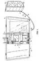
- a battery pack systemgenerally designated by the numeral 10, including a battery power pack 11 and a keeper battery pack 30.
- the battery power pack 11may be of known construction and includes a housing 12 connected by cables 13 to a pair of connector clamps 14, which can be respectively clamped onto the terminals of an automotive battery for purposes of jump-starting an associated vehicle engine, in a known manner.
- the battery power pack 11is illustrated as disposed in an associated carrying pouch 15, both of which may be of the type disclosed in the copending U.S. application serial no.
- the housing 12has a charger port 16 at one end thereof in the nature of a socket into which an associated charging device may be plugged.
- the housing 12may be provided with a display window 17 for an associated LCD display or the like coupled to suitable electronics in the housing 12.
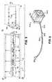
- a battery 18(FIG. 2) which may include one or more lead-acid cells, preferably of the thin metal film type.
- the battery power pack 11also includes a microcontroller 20 connected across the terminals of the battery 18, and a suitable power supply 21 also connected across the battery terminals 18 and also connected to the microcontroller 20 for providing a suitable operating voltage thereto.
- the microcontroller 20is also connected to a suitable display 22, which may be an LCD display and may be disposed in use beneath the display window 17 so as to be viewable therethrough.
- the terminals of the battery 18are connected to output terminals 25 and 26, respectively connected to the cables 13, and also connected to terminals of the charger port 16, which may be coaxial.
- the keeper battery pack 30has a housing 31 enclosing a plurality of series-connected alkaline cells 33, sufficient in number to generate an output voltage approximating a nominal normal operating voltage of the battery 18, in this case between 12 and 13 volts.
- the cells 33are C-cells or D-cells, each capable of generating 1.5 volts. Accordingly, nine such cells are connected in series in the housing 31 to produce an output voltage of 13.5 volts.
- the cells 33form a series array with end terminals respectively connected to conductors 36 and 37, which form a cable 3 5 extending outside the housing 31 and connected at its distal end to a plug connector 38, which may be of the coaxial type, and is adapted to be plugged into the charger port 16 of the battery power pack 11.
- a current limiting resistor 39is connected in series with the cells 33.
- the keeper pack 30may be connected thereto by plugging the plug connector 38 into the chargerport 16, whereupon the keeper battery pack 30 will provide a continuous trickle or keeper charge to the battery 18 to counteract the self discharge thereof, maintaining the nominal output voltage of the battery 18 and preventing its charge level from dropping to a dangerous level.
- the akaline cellsare easily replaceable when they become exhausted and the keeper battery pack 30 may be kept at the place of storage or transportation of the battery power pack 11 and connected thereto only when needed.
- keeper battery pack 30Awhich is similar to the keeper battery pack 30, wherefore like parts bear the same reference numerals with the suffix "A."
- the keeper battery pack 30Ahas a size and shape which are different from those of the pack 30, being in this case substantially rectangular and of a suitable size for housing nine 1.5-volt cells of the "AA" size. While the keeper battery pack 30A does not have the current capacity of the keeper battery pack 30, it has the advantage of small size, weight and expense. Otherwise, it works in the same manner described above for the keeper battery pack 30.
Landscapes
- Engineering & Computer Science (AREA)
- Power Engineering (AREA)
- Battery Mounting, Suspending (AREA)
- Charge And Discharge Circuits For Batteries Or The Like (AREA)
- Secondary Cells (AREA)
- Sealing Battery Cases Or Jackets (AREA)
Abstract
Description
Claims (9)
- A battery pack system comprising:an automotive battery of an associated vehicle;a battery power pack (11) which comprises:a first housing (12) including a battery (18), a charger port (16) and means (13, 14) forconnecting the battery power pack to the automotive battery for jump-starting theassociated vehicle; anda portable keeper battery pack (30) for providing a low-current keeper chargeto said battery power pack (11), which keeper battery pack (30) comprises:a second housing (31) separate from the first housing (12),an array of interconnected alkaline battery cells (33) disposed in the secondhousing (31),a current-limiting circuit (39) carried by the second housing (31) for limitingcurrent deliverable from the alkaline cells to a trickle level, anda cable (35) having an inner end connected to the array within the secondhousing (31) and an outer end disposed outside the second housing (31) and providedwith a quick-connect connector (38) removably electrically connectable to thecharger port (16) of the first housing (12).
- The battery pack system of claim 1, wherein each of the battery cells (33) is a 1.5-volt cell.
- The battery pack system of claim 2, wherein the array includes nine alkaline battery cells (33).
- The battery pack system of claim 1, wherein each of the battery cells (33) is a C-cell.
- The battery pack system of claim 1, wherein each of the battery cells (33) is a AA-cell.
- The battery pack system of claim 1, wherein each of the battery cells (33) is a D-cell.
- The battery pack system of claim 1, wherein the battery cells (33) are connected in series.
- The battery pack system of claim 7, and wherein the current-limiting circuit includes aresistor (39) in series with the battery cells (33).
- The battery pack system of claim 1, wherein the cable includes a pair of conductors (36,37) respectively connected to positive and negative terminals of the array.
Applications Claiming Priority (3)
| Application Number | Priority Date | Filing Date | Title |
|---|---|---|---|
| US09/611,045US6262559B1 (en) | 2000-07-06 | 2000-07-06 | Portable auxiliary charging battery pack for thin metal film battery power pack |
| US611045 | 2000-07-06 | ||
| PCT/US2001/020956WO2002005404A1 (en) | 2000-07-06 | 2001-06-29 | Portable charging battery pack for thin metal film battery |
Publications (3)
| Publication Number | Publication Date |
|---|---|
| EP1297600A1 EP1297600A1 (en) | 2003-04-02 |
| EP1297600A4 EP1297600A4 (en) | 2003-08-13 |
| EP1297600B1true EP1297600B1 (en) | 2005-01-26 |
Family
ID=24447396
Family Applications (1)
| Application Number | Title | Priority Date | Filing Date |
|---|---|---|---|
| EP01952359AExpired - LifetimeEP1297600B1 (en) | 2000-07-06 | 2001-06-29 | Portable battery pack system |
Country Status (7)
| Country | Link |
|---|---|
| US (1) | US6262559B1 (en) |
| EP (1) | EP1297600B1 (en) |
| AT (1) | ATE288145T1 (en) |
| AU (1) | AU2001273119A1 (en) |
| CA (1) | CA2382526A1 (en) |
| DE (1) | DE60108634D1 (en) |
| WO (1) | WO2002005404A1 (en) |
Cited By (1)
| Publication number | Priority date | Publication date | Assignee | Title |
|---|---|---|---|---|
| CN108884801A (en)* | 2016-02-11 | 2018-11-23 | 尼科公司 | The battery connector device of electric starter is taken for battery |
Families Citing this family (24)
| Publication number | Priority date | Publication date | Assignee | Title |
|---|---|---|---|---|
| US7038333B2 (en) | 2002-02-15 | 2006-05-02 | The Gillette Company | Hybrid power supply |
| US7471062B2 (en)* | 2002-06-12 | 2008-12-30 | Koninklijke Philips Electronics N.V. | Wireless battery charging |
| JP4267674B2 (en)* | 2004-03-08 | 2009-05-27 | ベゲリー ソシエタ ペル アチオニ | Battery recharging device |
| US8456130B2 (en) | 2005-11-18 | 2013-06-04 | Moto Boost International, Llc | Method and apparatus for utilizing recycled batteries to surface charge an automobile battery |
| US7915856B2 (en)* | 2006-03-10 | 2011-03-29 | Spx Corporation | Battery testing and/or charging system with integrated receptacle and pass-through power for booster pack and method of using same |
| US7825615B2 (en) | 2007-10-16 | 2010-11-02 | Glj, Llc | Intelligent motorized appliances with multiple power sources |
| US20120191517A1 (en) | 2010-12-15 | 2012-07-26 | Daffin Jr Mack Paul | Prepaid virtual card |
| CN103066662B (en) | 2013-01-07 | 2015-08-05 | 雷星亮 | emergency power supply |
| US11565598B2 (en) | 2013-03-15 | 2023-01-31 | Symbotic Llc | Rover charging system with one or more charging stations configured to control an output of the charging station independent of a charging station status |
| US11458851B2 (en) | 2014-07-03 | 2022-10-04 | The Noco Company | Jump starting apparatus |
| US9007015B1 (en)* | 2014-07-03 | 2015-04-14 | The Noco Company | Portable vehicle battery jump start apparatus with safety protection |
| EP3264515B1 (en) | 2016-06-30 | 2019-04-03 | Shenzhen Carku Technology Co., Ltd. | Smart battery jumper cable |
| US12074434B2 (en) | 2017-09-22 | 2024-08-27 | The Noco Company | Portable vehicle battery jump starter with air pump |
| AU2018403192B2 (en) | 2017-12-14 | 2022-02-10 | The Noco Company | Portable vehicle battery jump starter with air pump |
| USD867985S1 (en) | 2017-12-21 | 2019-11-26 | The Noco Company | Combination jump starter and display |
| USD913934S1 (en) | 2018-10-01 | 2021-03-23 | The Noco Company | Battery clamp |
| USD913935S1 (en) | 2018-10-01 | 2021-03-23 | The Noco Company | Battery clamp |
| USD997102S1 (en) | 2018-10-03 | 2023-08-29 | The Noco Company | Battery clamp |
| USD913937S1 (en) | 2018-10-03 | 2021-03-23 | The Noco Company | Battery clamp |
| USD913938S1 (en) | 2018-10-03 | 2021-03-23 | The Noco Company | Battery clamp |
| USD967025S1 (en) | 2018-10-05 | 2022-10-18 | The Noco Company | Battery clamp |
| USD984381S1 (en) | 2020-11-25 | 2023-04-25 | The Noco Company | Battery cable assembly for jump starting device |
| USD991185S1 (en) | 2020-12-11 | 2023-07-04 | The Noco Company | Battery cable assembly |
| USD991186S1 (en) | 2020-12-11 | 2023-07-04 | The Noco Company | Battery cable assembly |
Family Cites Families (15)
| Publication number | Priority date | Publication date | Assignee | Title |
|---|---|---|---|---|
| US979154A (en)* | 1909-11-06 | 1910-12-20 | Julius H Gugler | Combined primary and secondary battery system. |
| JPS5323489B1 (en)* | 1965-11-17 | 1978-07-14 | ||
| FR2335987A1 (en) | 1975-12-18 | 1977-07-15 | Bicosa Recherches | IMPROVEMENTS TO DIRECT CURRENT POWER SUPPLIES, ESPECIALLY OF THE DISPOSABLE TYPE, SUITABLE TO PROVIDE A NOMINAL VOLTAGE OF DETERMINED VALUE |
| US4692680A (en)* | 1985-08-12 | 1987-09-08 | Seacliff International, Inc. | Portable battery charging apparatus and methods therefor |
| US4857820A (en) | 1987-09-08 | 1989-08-15 | Tompkins John C | Cordless battery charger |
| US5107197A (en) | 1989-01-04 | 1992-04-21 | Arlinghaus Albert J | Jump start system |
| US5250891A (en) | 1991-05-13 | 1993-10-05 | Milwaukee Electric Tool Corporation | Battery charging method and apparatus |
| US5281904A (en) | 1992-09-29 | 1994-01-25 | Innova Electronics | Multi mode cordless battery charger |
| JPH07154924A (en)* | 1993-11-26 | 1995-06-16 | Nec Corp | Battery usage system for portable electronic device |
| US5686809A (en)* | 1995-05-12 | 1997-11-11 | Fuji Photo Film Co., Ltd. | Combination solar and external battery powered camera battery charger |
| JPH0937478A (en) | 1995-07-21 | 1997-02-07 | Hitachi Koki Co Ltd | Charger |
| US5883491A (en)* | 1997-03-06 | 1999-03-16 | Silverman; Martin S. | Method and apparatus for depositing an electrical charge to an electrical storage cell used in an automobile |
| US5993983C1 (en)* | 1997-03-14 | 2001-09-18 | Century Mfg Co | Portable power supply using hybrid battery technology |
| US6002235A (en)* | 1999-02-17 | 1999-12-14 | Bonnet Enterprises Llc | Battery jump starter with jaw securing means |
| WO2000054359A1 (en)* | 1999-03-11 | 2000-09-14 | Bolder Technologies Corporation | Dual battery systems and methods for maintaining the charge state of high power batteries |
- 2000
- 2000-07-06USUS09/611,045patent/US6262559B1/ennot_activeExpired - Fee Related
- 2001
- 2001-06-29DEDE60108634Tpatent/DE60108634D1/ennot_activeExpired - Lifetime
- 2001-06-29EPEP01952359Apatent/EP1297600B1/ennot_activeExpired - Lifetime
- 2001-06-29AUAU2001273119Apatent/AU2001273119A1/ennot_activeAbandoned
- 2001-06-29ATAT01952359Tpatent/ATE288145T1/ennot_activeIP Right Cessation
- 2001-06-29WOPCT/US2001/020956patent/WO2002005404A1/enactiveIP Right Grant
- 2001-06-29CACA 2382526patent/CA2382526A1/ennot_activeAbandoned
Cited By (1)
| Publication number | Priority date | Publication date | Assignee | Title |
|---|---|---|---|---|
| CN108884801A (en)* | 2016-02-11 | 2018-11-23 | 尼科公司 | The battery connector device of electric starter is taken for battery |
Also Published As
| Publication number | Publication date |
|---|---|
| US6262559B1 (en) | 2001-07-17 |
| EP1297600A4 (en) | 2003-08-13 |
| CA2382526A1 (en) | 2002-01-17 |
| EP1297600A1 (en) | 2003-04-02 |
| ATE288145T1 (en) | 2005-02-15 |
| AU2001273119A1 (en) | 2002-01-21 |
| WO2002005404A1 (en) | 2002-01-17 |
| DE60108634D1 (en) | 2005-03-03 |
Similar Documents
| Publication | Publication Date | Title |
|---|---|---|
| EP1297600B1 (en) | Portable battery pack system | |
| US6140797A (en) | Compact improved autonomous auxiliary engine starting apparatus | |
| EP1201006B1 (en) | Rechargeable battery packs | |
| CA1226618A (en) | Battery recharger | |
| US6154007A (en) | Battery charging system and method | |
| CN101675555B (en) | Battery pack and battery system | |
| US5993983A (en) | Portable power supply using hybrid battery technology | |
| US20070247105A1 (en) | Portable battery charger | |
| US10862176B2 (en) | Portable rechargeable battery pack with a selectable battery switch and state of charge display for cordless power tools | |
| US5352966A (en) | Battery charging device | |
| US20030090162A1 (en) | Power tool and convertible remote battery pack therefor | |
| US20220149641A1 (en) | Modular portable power station with battery expansion | |
| CN101796704A (en) | Assembled battery and battery system | |
| US12003125B2 (en) | Tool circuitry for series-type connected battery packs | |
| US20060082345A1 (en) | Rechargeable alkaline battery with overcharging protection | |
| CN2442397Y (en) | Accumulator management device | |
| Documentation | User guide | |
| JPH06502288A (en) | Carrying case assemblies for portable electrical devices | |
| JP2006141187A (en) | Power tank | |
| JPH1146453A (en) | Simple charging device for portable telephone | |
| CN218005925U (en) | High-efficient charging device of series battery | |
| US7056619B2 (en) | Chargeable battery for medical diagnostic instruments | |
| WO2009094487A1 (en) | Backup power source and charger for mobile devices | |
| JP3044876U (en) | Charging device | |
| JPH09180764A (en) | Rechargeable battery pack |
Legal Events
| Date | Code | Title | Description |
|---|---|---|---|
| PUAI | Public reference made under article 153(3) epc to a published international application that has entered the european phase | Free format text:ORIGINAL CODE: 0009012 | |
| 17P | Request for examination filed | Effective date:20020104 | |
| AK | Designated contracting states | Kind code of ref document:A1 Designated state(s):AT BE CH CY DE DK ES FI FR GB GR IE IT LI LU MC NL PT SE TR Designated state(s):AT BE CH CY DE DK ES FI FR GB GR IE IT LI LU MC NL PT SE TR | |
| AX | Request for extension of the european patent | Extension state:AL LT LV MK RO SI | |
| A4 | Supplementary search report drawn up and despatched | Effective date:20030626 | |
| RIC1 | Information provided on ipc code assigned before grant | Ipc:7H 01M 10/44 B Ipc:7H 02J 7/34 B Ipc:7H 02J 7/00 A | |
| 17Q | First examination report despatched | Effective date:20030902 | |
| GRAP | Despatch of communication of intention to grant a patent | Free format text:ORIGINAL CODE: EPIDOSNIGR1 | |
| RAP1 | Party data changed (applicant data changed or rights of an application transferred) | Owner name:SNAP-ON INCORPORATED | |
| RAP1 | Party data changed (applicant data changed or rights of an application transferred) | Owner name:SNAP-ON INCORPORATED | |
| RTI1 | Title (correction) | Free format text:PORTABLE BATTERY PACK SYSTEM | |
| RAP1 | Party data changed (applicant data changed or rights of an application transferred) | Owner name:SNAP-ON INCORPORATED | |
| GRAS | Grant fee paid | Free format text:ORIGINAL CODE: EPIDOSNIGR3 | |
| GRAA | (expected) grant | Free format text:ORIGINAL CODE: 0009210 | |
| AK | Designated contracting states | Kind code of ref document:B1 Designated state(s):AT BE CH CY DE DK ES FI FR GB GR IE IT LI LU MC NL PT SE TR | |
| AX | Request for extension of the european patent | Extension state:AL LT LV MK RO SI | |
| PG25 | Lapsed in a contracting state [announced via postgrant information from national office to epo] | Ref country code:TR Free format text:LAPSE BECAUSE OF FAILURE TO SUBMIT A TRANSLATION OF THE DESCRIPTION OR TO PAY THE FEE WITHIN THE PRESCRIBED TIME-LIMIT Effective date:20050126 Ref country code:NL Free format text:LAPSE BECAUSE OF FAILURE TO SUBMIT A TRANSLATION OF THE DESCRIPTION OR TO PAY THE FEE WITHIN THE PRESCRIBED TIME-LIMIT Effective date:20050126 Ref country code:LI Free format text:LAPSE BECAUSE OF FAILURE TO SUBMIT A TRANSLATION OF THE DESCRIPTION OR TO PAY THE FEE WITHIN THE PRESCRIBED TIME-LIMIT Effective date:20050126 Ref country code:IT Free format text:LAPSE BECAUSE OF FAILURE TO SUBMIT A TRANSLATION OF THE DESCRIPTION OR TO PAY THE FEE WITHIN THE PRESCRIBED TIME-LIMIT;WARNING: LAPSES OF ITALIAN PATENTS WITH EFFECTIVE DATE BEFORE 2007 MAY HAVE OCCURRED AT ANY TIME BEFORE 2007. THE CORRECT EFFECTIVE DATE MAY BE DIFFERENT FROM THE ONE RECORDED. Effective date:20050126 Ref country code:FR Free format text:LAPSE BECAUSE OF NON-PAYMENT OF DUE FEES Effective date:20050126 Ref country code:FI Free format text:LAPSE BECAUSE OF FAILURE TO SUBMIT A TRANSLATION OF THE DESCRIPTION OR TO PAY THE FEE WITHIN THE PRESCRIBED TIME-LIMIT Effective date:20050126 Ref country code:CH Free format text:LAPSE BECAUSE OF FAILURE TO SUBMIT A TRANSLATION OF THE DESCRIPTION OR TO PAY THE FEE WITHIN THE PRESCRIBED TIME-LIMIT Effective date:20050126 Ref country code:BE Free format text:LAPSE BECAUSE OF FAILURE TO SUBMIT A TRANSLATION OF THE DESCRIPTION OR TO PAY THE FEE WITHIN THE PRESCRIBED TIME-LIMIT Effective date:20050126 Ref country code:AT Free format text:LAPSE BECAUSE OF FAILURE TO SUBMIT A TRANSLATION OF THE DESCRIPTION OR TO PAY THE FEE WITHIN THE PRESCRIBED TIME-LIMIT Effective date:20050126 | |
| REG | Reference to a national code | Ref country code:GB Ref legal event code:FG4D | |
| REG | Reference to a national code | Ref country code:CH Ref legal event code:EP | |
| REG | Reference to a national code | Ref country code:IE Ref legal event code:FG4D | |
| REF | Corresponds to: | Ref document number:60108634 Country of ref document:DE Date of ref document:20050303 Kind code of ref document:P | |
| PG25 | Lapsed in a contracting state [announced via postgrant information from national office to epo] | Ref country code:SE Free format text:LAPSE BECAUSE OF FAILURE TO SUBMIT A TRANSLATION OF THE DESCRIPTION OR TO PAY THE FEE WITHIN THE PRESCRIBED TIME-LIMIT Effective date:20050426 Ref country code:GR Free format text:LAPSE BECAUSE OF FAILURE TO SUBMIT A TRANSLATION OF THE DESCRIPTION OR TO PAY THE FEE WITHIN THE PRESCRIBED TIME-LIMIT Effective date:20050426 Ref country code:DK Free format text:LAPSE BECAUSE OF FAILURE TO SUBMIT A TRANSLATION OF THE DESCRIPTION OR TO PAY THE FEE WITHIN THE PRESCRIBED TIME-LIMIT Effective date:20050426 | |
| PG25 | Lapsed in a contracting state [announced via postgrant information from national office to epo] | Ref country code:DE Free format text:LAPSE BECAUSE OF FAILURE TO SUBMIT A TRANSLATION OF THE DESCRIPTION OR TO PAY THE FEE WITHIN THE PRESCRIBED TIME-LIMIT Effective date:20050427 | |
| PG25 | Lapsed in a contracting state [announced via postgrant information from national office to epo] | Ref country code:ES Free format text:LAPSE BECAUSE OF FAILURE TO SUBMIT A TRANSLATION OF THE DESCRIPTION OR TO PAY THE FEE WITHIN THE PRESCRIBED TIME-LIMIT Effective date:20050507 | |
| LTIE | Lt: invalidation of european patent or patent extension | Effective date:20050126 | |
| PG25 | Lapsed in a contracting state [announced via postgrant information from national office to epo] | Ref country code:LU Free format text:LAPSE BECAUSE OF NON-PAYMENT OF DUE FEES Effective date:20050629 Ref country code:IE Free format text:LAPSE BECAUSE OF NON-PAYMENT OF DUE FEES Effective date:20050629 Ref country code:GB Free format text:LAPSE BECAUSE OF NON-PAYMENT OF DUE FEES Effective date:20050629 Ref country code:CY Free format text:LAPSE BECAUSE OF FAILURE TO SUBMIT A TRANSLATION OF THE DESCRIPTION OR TO PAY THE FEE WITHIN THE PRESCRIBED TIME-LIMIT Effective date:20050629 | |
| PG25 | Lapsed in a contracting state [announced via postgrant information from national office to epo] | Ref country code:MC Free format text:LAPSE BECAUSE OF NON-PAYMENT OF DUE FEES Effective date:20050630 | |
| NLV1 | Nl: lapsed or annulled due to failure to fulfill the requirements of art. 29p and 29m of the patents act | ||
| REG | Reference to a national code | Ref country code:CH Ref legal event code:PL | |
| PLBE | No opposition filed within time limit | Free format text:ORIGINAL CODE: 0009261 | |
| STAA | Information on the status of an ep patent application or granted ep patent | Free format text:STATUS: NO OPPOSITION FILED WITHIN TIME LIMIT | |
| 26N | No opposition filed | Effective date:20051027 | |
| GBPC | Gb: european patent ceased through non-payment of renewal fee | Effective date:20050629 | |
| REG | Reference to a national code | Ref country code:IE Ref legal event code:MM4A | |
| EN | Fr: translation not filed | ||
| PG25 | Lapsed in a contracting state [announced via postgrant information from national office to epo] | Ref country code:PT Free format text:LAPSE BECAUSE OF NON-PAYMENT OF DUE FEES Effective date:20050626 |