EP1297230B1 - Flashing assembly with flexible flange members - Google Patents
Flashing assembly with flexible flange membersDownload PDFInfo
- Publication number
- EP1297230B1 EP1297230B1EP01938018AEP01938018AEP1297230B1EP 1297230 B1EP1297230 B1EP 1297230B1EP 01938018 AEP01938018 AEP 01938018AEP 01938018 AEP01938018 AEP 01938018AEP 1297230 B1EP1297230 B1EP 1297230B1
- Authority
- EP
- European Patent Office
- Prior art keywords
- flashing
- sheet portion
- flexible
- flange member
- sheet
- Prior art date
- Legal status (The legal status is an assumption and is not a legal conclusion. Google has not performed a legal analysis and makes no representation as to the accuracy of the status listed.)
- Expired - Lifetime
Links
- 230000006835compressionEffects0.000claimsabstractdescription7
- 238000007906compressionMethods0.000claimsabstractdescription7
- 238000005452bendingMethods0.000claimsdescription13
- 239000000463materialSubstances0.000description22
- 230000006978adaptationEffects0.000description9
- 239000011295pitchSubstances0.000description8
- 230000000149penetrating effectEffects0.000description7
- 229910052751metalInorganic materials0.000description6
- 239000002184metalSubstances0.000description6
- 238000004519manufacturing processMethods0.000description5
- XLYOFNOQVPJJNP-UHFFFAOYSA-NwaterSubstancesOXLYOFNOQVPJJNP-UHFFFAOYSA-N0.000description3
- 239000004411aluminiumSubstances0.000description2
- 229910052782aluminiumInorganic materials0.000description2
- XAGFODPZIPBFFR-UHFFFAOYSA-NaluminiumChemical compound[Al]XAGFODPZIPBFFR-UHFFFAOYSA-N0.000description2
- 230000000712assemblyEffects0.000description2
- 238000000429assemblyMethods0.000description2
- 238000007789sealingMethods0.000description2
- 238000004078waterproofingMethods0.000description2
- 241000743339AgrostisSpecies0.000description1
- RYGMFSIKBFXOCR-UHFFFAOYSA-NCopperChemical compound[Cu]RYGMFSIKBFXOCR-UHFFFAOYSA-N0.000description1
- 229910000831SteelInorganic materials0.000description1
- ATJFFYVFTNAWJD-UHFFFAOYSA-NTinChemical compound[Sn]ATJFFYVFTNAWJD-UHFFFAOYSA-N0.000description1
- HCHKCACWOHOZIP-UHFFFAOYSA-NZincChemical compound[Zn]HCHKCACWOHOZIP-UHFFFAOYSA-N0.000description1
- 238000009825accumulationMethods0.000description1
- 239000005030aluminium foilSubstances0.000description1
- 239000010426asphaltSubstances0.000description1
- 239000002131composite materialSubstances0.000description1
- 238000010276constructionMethods0.000description1
- 229910052802copperInorganic materials0.000description1
- 239000010949copperSubstances0.000description1
- 239000011162core materialSubstances0.000description1
- 230000003628erosive effectEffects0.000description1
- 238000011065in-situ storageMethods0.000description1
- 230000010354integrationEffects0.000description1
- 230000008018meltingEffects0.000description1
- 238000002844meltingMethods0.000description1
- 239000003973paintSubstances0.000description1
- 230000000704physical effectEffects0.000description1
- 239000002861polymer materialSubstances0.000description1
- 230000003014reinforcing effectEffects0.000description1
- 238000007493shaping processMethods0.000description1
- 239000010959steelSubstances0.000description1
- 230000003313weakening effectEffects0.000description1
- 239000011701zincSubstances0.000description1
- 229910052725zincInorganic materials0.000description1
Images


Classifications
- E—FIXED CONSTRUCTIONS
- E04—BUILDING
- E04D—ROOF COVERINGS; SKY-LIGHTS; GUTTERS; ROOF-WORKING TOOLS
- E04D13/00—Special arrangements or devices in connection with roof coverings; Protection against birds; Roof drainage ; Sky-lights
- E04D13/14—Junctions of roof sheathings to chimneys or other parts extending above the roof
- E04D13/147—Junctions of roof sheathings to chimneys or other parts extending above the roof specially adapted for inclined roofs
- E04D13/1473—Junctions of roof sheathings to chimneys or other parts extending above the roof specially adapted for inclined roofs specially adapted to the cross-section of the parts extending above the roof
- E04D13/1475—Junctions of roof sheathings to chimneys or other parts extending above the roof specially adapted for inclined roofs specially adapted to the cross-section of the parts extending above the roof wherein the parts extending above the roof have a generally rectangular cross-section
- E—FIXED CONSTRUCTIONS
- E04—BUILDING
- E04D—ROOF COVERINGS; SKY-LIGHTS; GUTTERS; ROOF-WORKING TOOLS
- E04D13/00—Special arrangements or devices in connection with roof coverings; Protection against birds; Roof drainage ; Sky-lights
- E04D13/02—Roof-covering aspects of dormer windows
Definitions
- the present inventionrelates to a flashing assembly
- a flashing assemblycomprising first and second workable sheet flashings each having at least one sheet portion and at least one flange member, an edge of the flange member being connected to the sheet portion, the flange member being arranged at an angle relative to the plane of the sheet portion and being flexible so that it is capable of stretching and/or compression preferably along the edge opposite to the edge connected to the sheet portion when working the sheet portion.
- flashing roof penetrating building structuresfor example chimneys or frame structures for roof windows
- flashing coversof sheet metal, for instance aluminium, copper, steel or zinc.
- flashingshave been manufactures by ordinary tin man work from a plane sheet material, which is profiled and formed to make a fit at the desired location.
- one of the flashing membersare normally provided with a flange along an edge thereof, which is arranged in an overlapping fashion with the neighbouring flashing member.
- EP-A-0 792 977describes a flashing for a chimney made entirely from corrugated material, being adaptable to virtually any size and shape of the chimney, to any pitch of the roof, and to any shaping of the roof covering.
- corrugated materialhas a number of disadvantages; it is much more expensive than plane sheet flashings per unit area, the folds may cause capillary ascension thereby fixing water in the flashing, and the uneven surface may hinder the draining of the flashing and further tends to trap dirt and to be difficult to clean leading to accelerated erosion and an undesirable appearance.
- the former two publicationsdescribe flashing members designed for proofing the corners of a single roof penetrating element, e.g. a chimney.
- the latterdescribes a flashing member with a bendable sheet portion for use with curved structures, such as a façade window with a semicircular top section.
- DE-A-36 03 303discloses a planar flashing manufactured in either plastic or sheet metal and comprising a corrugated or pleated intermediate portion, this portion allowing the flashing to be stretched or bend, however only in the plane of the sheet metal.
- two separate flashing membersare arranged relative to each other in a sealing manner.
- a flashing assemblywhere said first and said second workable sheet flashings are adapted to be mounted in an overriding fashion with a downward oriented flexible flange member of one flashing overlapping an upward oriented flexible flange member of another flashing.
- the overlapping manner in which the flange are arrangedis the same as for a conventional type flashing and provides a natural path of drainage for rain, melting snow or the like, that needs to be lead away from the roof and in particular from junctions where a leakage would cause the most damage.
- Combining this well known way of proofing with the use of flexible flange membersprovides an unprecedented opportunity for adaptation to the specific pitch, ridge angle and other characteristics of the roof and the roof-penetrating element, which allows for a very good and tight waterproofing.
- the flashings used in the present inventioncan be manufactured from any suitable material, for example a metal or a polymeric material, this with respect to both the sheet portions and the stretchable and/or compressible flange portions. Different materials could also be chosen for the different parts of the flashings. For some applications also laminates could be used, for example for the corrugated or pleated portions. However, the material should normally be so sufficiently soft that bending or adaptation of angles of the flashings can be done manually, preferably by use of hand pressure only.
- flangedoes not indicate or imply any relative dimensions; in fact, the flange may be wider or broader than the sheet portion of the flashing.
- membermeans that the flexible flange member may be part of a composite flange, which also comprises non-flexible members.
- the flexible flange members of the flashingsare arranged substantially perpendicular to the plane of the sheet portions. This way of arranging the flanges ensures the tight connection between the flashing members, whereas the use of more oblique angles makes it harder to spot irregularities originating in for example production errors or damaged caused during transportation.
- the oblique anglesmay be preferable, i.e. if the sheet portion of the lower flashing cannot be located sufficiently close to the upper flashing for perpendicular flanges to overlap properly.
- the flexible flange membersare pleated or corrugated structures.
- the pleating or corrugationallows the flange members to take up the surplus of material that arises from compression thereof, thereby preventing buckling, and allows a stretching of the flange normally without stretching of the material itself, thereby avoiding a potential weakening of the material.
- a first flashingcomprises two sheet portions interconnected by a hinge member.
- Flashing members with build-in hingesare particularly useful for flashing of groups of roof penetrating elements arranged on both sides of a ridge, as the hinge allows for an adaptation to the angle of the ridge.
- the sheet material of the flashingis workable, for instance bendable, in itself, the only purpose of adding the hinge is to improve the ability to bend.
- the hingeshould be considered to be part of the sheet portion of the flashing.
- the hinge memberis a pleated or corrugated structure.
- a flexible flange memberis formed integrally with the hinge member. This not only ensures an improved tightness of the flashing, it also makes the manufacture thereof easier, as fewer parts have to be joined. In spite of the one-piece build, the hinge should still, as mentioned above, be considered part of the sheet portion, while the flexible flange is of cause not part thereof.
- a first flashingcomprises two flange portions arranged along an edge of the sheet portion at an angle thereto and on each side of the flexible flange member, the flexible flange member being attached to the flange portions at respective ends thereof facing the flexible member.
- a first flashingcomprises a plurality of flexible flange members attached to various edges of the sheet portion.
- a flexible flangewherever there is a possibility that an edge might be bent, as the bending might cause a slight lift of the edge, which might otherwise leave an opening in the flashing.
- the sheet portionis open-ended trough-shaped.
- the flashingwill then have a pronounced capability of leading the water in the right direction and at the same time it will serve as a buffer hindering the accumulation of water in other places, where it may be less desirable.
- the troughhas one or more ramifications. This may for instance be the case, if three roof-penetrating parts meet where the hip of a hipped roof meets the ridge.
- trough-shaped flashingshave flexible flange members attached to bent end edges, as these edges are the ones over which rainwater and the like will flow.
- all flexible flange membersare capable of expansion corresponding to a bending angle of the sheet portion of at least 5 degrees, more preferably more than 15 degrees, and most preferably more than 30 degrees
- the inventionfurther relates to flashing assemblies comprising bendable sheet flashings as described in claims 14 and 15
- flashingsmay be formed so that the flexible flange member covers only part of the edge of the sheet portion to which it is attached. This limits the amount
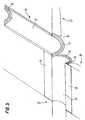
- the flashing assembly of Fig. 1is designed for proofing of a pair of windows 1,2 mounted end-to-end or top-at-top at the ridge 3 of a roof providing a seal between the roof surface 4 and the windows as well as between the ends or tops 5 of the windows.
- both windowsare mounted as roof penetrating building structures with outer frame surfaces 5,6,7 protruding through the roof surface, the outer side surfaces 6,7 being arranged substantially perpendicular to the roof surface 4.
- the flashing assembly for proofing this structureconsist of a plurality of parts, but for the sake of simplicity only four are shown, namely a ridge flashing 8 for the junction between the roof and the windows, a trough flashing 9 for the junction between the two windows, and top flashings 10,11 for the junction between each window and the other flashings. It is to be understood, that an identical counterpart (not shown) to the ridge flashing 8 is employed on the other side of the windows 1,2.
- the mounting of the flashing assemblybegins with the mounting of the ridge flashings 8, which are arranged riding over the ridge 3, flanges 12,13 of the ridge flashings 8 abutting the protruding frame surfaces 6,7 of the windows 1,2.
- the ridge flashings 8comprise first and second members each having a roof portion 14,15 and a flange portion 12,13 arranged substantially perpendicular relative to the corresponding roof portion.
- the roof portions 14,15are connected by a flexible hinge member 16 and the flange portions are connected by a flexible flange member 17, the hinged construction allowing an easy adaptation of the ridge flashing to the specific angle of the roof ridge 3.
- the flexible flange member 17 and the flexible hinge 16are made from pleated or corrugated material.
- the flexible flange member 17may have the same extent as the non-flexible flanges 12,13 or, as shown, it may be shorter seen in the direction of the folds of the corrugation. As can be seen at the flange portions 12,13 the flexible members 16, 17 are connected to the respective edges of the roof and flange portions 12,13,14,15 by bending over the edges thereof. The attachment of the flexible flange member 17 to the non-flexible flange members 12,13 assures a continuous flange even when the ridge flashing is bent, this allowing an adaptation to any given ridge angle without loss of tightness.
- the flexible flange member 17is formed integrally with the hinge member 16, allowing the ridge flashing to be manufactured as a flat intermediate member which is subsequently bent along a line perpendicular to the length axis of the hinge member 16 to thereby produce the flange portions 12,13,17. Also the integration of the flexible hinge 16 and flange 17 improves the tightness of the proofing.
- This flashingcomprises a longitudinal main member 18 having an overall trough-like configuration, and at each end thereof having a flange member 19 arranged substantially perpendicular to the main member 18.
- the flange membersare preferably made from corrugated or pleated material and they may extent partly or fully, as shown, along the opposing ends of the flashing.
- the flexible flange membersare connected to the respective ends of the trough flashing by bending over the edges thereof (not shown).
- the trough flashingfurther comprises flanges 20,21 which serves both as sealing and reinforcing elements.
- the through flashing 9is preferably pre-bent to the specific angle between the two window frames but may also be bent manually. However, if the flashing is made from a painted sheet material or a laminate, excessive manual bending could cause ruptures in the paint or the connection between the layers of the laminate. Thus, extensive manual bending of these types of flashings should preferably be carried out with caution.
- the downwards projecting flange members of the through flashing 9are overlapping the upwards projecting flange members 12,13,17 of the ridge flashing 3.
- the flange members of both the ridge and the trough flashingare substantially perpendicular to the sheet portions thereof, however, the flange members may be attached in any angle, as long as they are adapted to each other so that a tight proofing can be obtained.
- top flashings 10,11are mounted. These flashings are substantially C-shaped and adapted to seal between the ends or tops 5 of the windows and the other flashing members. Naturally further flashing elements than the ones shown will have to be mounted in order to provide a full flashing around the two windows, these element, however, will not be described as they are well known to those skilled in the art.
- the flashing assembly in Fig. 1 and 2 or at least the ridge flashing 8 thereofare normally arranged onto a lower roof surface before the completion of the roof covering.
- the flashing assemblyhas a pronounced ability for adaptation to the specific pitch of the roof and thus the ridge angle, making the flashing applicable for virtually any type of roof.
- the assemblyhas only limited possibilities, as the flange width of the ridge flashing 8 must correspond with the height of the protruding part 6,7 of the window frames and as the trough flashing 9 has to have the same length as the tops or ends 5 of the window frames.
- the trough flashing 9may instead be manufactured as two individual halves and mounted in an overlapping manner, the size of the overlap deciding the length of the trough flashing.
- the ridge flashing adaptationwould mean cutting it to size in-situ.
- FIG. 2the flashing assembly of Fig. 1 is shown in its assembled state, where like element are numbered with the same reference numerals as in Fig. 1 .
- the elements 22, 23, 24 and 25are further flashing elements in addition to those described with reference to Fig. 1 .
- Fig. 3shows a flashing assembly for two neighbouring groups 26,27 of windows each consisting of at least two windows arranged in a clinker fashion.
- the distances between the windowsare necessary, as windows overlapping the load-bearing framework of the roof are seldom architecturally appropriate.
- the flashingcomprises two types of trough flashings 28,29, both having a substantially U-shaped cross section, though the shape of the cross section of the trough is of no significance.
- the first type 28, which is used for proofing the downward space 30 between the two groupsis very similar to the trough flashing in Fig. 1 and 2 , only the flexible flanges 31,32 are arranged on opposite sides of the sheet portion 33, one being upward 31, the other being downward 32 as in Fig. 1 .
- the flexible flanges 31,32may cover the entire edge to which it is attached or only the bottom part of the U-shape.
- this first type of flashingis mounted, the end with the downward flange 32 is turned downward on the roof and overlapping the upward flange 31 of the next flashing further down the roof. It may take one, as shown, or more flashings to cover the length of a window and the flashings may be formed from overlapping parts to enable an adaptation to a specific size of the window.
- the second type of flashing 29is used for proofing the substantially horizontal space 34 between the windows of each group.
- This type of flashinghas flanges 35,36 arranged along the edges of the trough 37 in its length direction to seal the junction between the windows and the space 34 there between.
- the flashinghas a downward flexible flange 38, which in the assembled state overlaps the edge of the first type of flashing 28.
- the first type flashing 28may also be provided with an upward flange (not shown) at the part of the edge abutting the flexible flange 38 of the second type flashing 29.
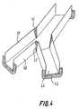
- Fig. 4shows a flashing that is designed for use where roof-penetrating elements on three roof surfaces meet, e.g. where the hip of a hipped roof meets the ridge.
- the flashinghas the configuration of a substantially Y-shaped trough, which is bent at the ramifications to fit the shaped of the roof.
- the upright parts 39,40are provided with hinge-like structures 41,42 to enable the upper edges to be stretched or compressed when the flashing is adapted to the roof.
- the flashinghas downward flexible flange members 43 that are meant to interact with upward flange members of other flashings, i.e. trough flashings like the ones in Fig. 3 .
- the flangesare flexible to allow a slight inward or outward bending of the uprights parts 39,40. As the trough of this embodiment has sharp corners, the bending will primarily work there, but some bending of the upright parts 39,40 and of the bottom part 44 cannot be excluded. Therefore the entire flange has to be flexible.
- the flashingscan be manufactured from any suitable material, however, the sheet portion are preferably made from painted or plated sheet aluminium with a thickness from 0,5 to 3 mm and the flexible flange member from a corrugated or pleated laminate, for example a core material of a pliable bitumen or polymer material covered on both sides with an aluminium foil.
Landscapes
- Engineering & Computer Science (AREA)
- Architecture (AREA)
- Civil Engineering (AREA)
- Structural Engineering (AREA)
- Tents Or Canopies (AREA)
- Roof Covering Using Slabs Or Stiff Sheets (AREA)
Abstract
Description
- The present invention relates to a flashing assembly comprising first and second workable sheet flashings each having at least one sheet portion and at least one flange member, an edge of the flange member being connected to the sheet portion, the flange member being arranged at an angle relative to the plane of the sheet portion and being flexible so that it is capable of stretching and/or compression preferably along the edge opposite to the edge connected to the sheet portion when working the sheet portion.
- When flashing roof penetrating building structures, for example chimneys or frame structures for roof windows, in order to protect them from the weather and to provide a seal between the structure itself and the roof, it is common to use flashing covers of sheet metal, for instance aluminium, copper, steel or zinc. Conventionally, such flashings have been manufactures by ordinary tin man work from a plane sheet material, which is profiled and formed to make a fit at the desired location. In order to provide a seal between, for example, two flashing members arranged perpendicular to each other, one of the flashing members are normally provided with a flange along an edge thereof, which is arranged in an overlapping fashion with the neighbouring flashing member.
- The comparatively costly adjustment and assembly work on location, which is required when using this conventional craftsmanship, may be avoided by use of pre-manufactured flashing members. When these flashing members are used with, for example, a standard window type mounted in a given roof surface, it is possible to use the same "standard" flashing member regardless of the slope of the roof surface.
- However, some types of roof penetrating building structures cannot be proofed with "standard" type flashing members as they are, for example, riding over the roof ridge and therefore depending upon the ridge angle. For these types of flashings, a whole "family" of pre-manufactured members would be needed, one variant for each possible pitch of the roof, something that would add greatly to the costs, both for manufacturing and stock keeping.
- Although a given number of such variants may cover the roof pitches most commonly used, there would still be a need to either re-work the pre-manufactured flashing members to make them fit the "non-standard" roof pitches.
- In the past there have been several attempts to provide flashing members as well as entire flashings, which are flexible so as to be adaptable under different circumstances.
EP-A-0 792 977 describes a flashing for a chimney made entirely from corrugated material, being adaptable to virtually any size and shape of the chimney, to any pitch of the roof, and to any shaping of the roof covering. However, the extensive use of corrugated material has a number of disadvantages; it is much more expensive than plane sheet flashings per unit area, the folds may cause capillary ascension thereby fixing water in the flashing, and the uneven surface may hinder the draining of the flashing and further tends to trap dirt and to be difficult to clean leading to accelerated erosion and an undesirable appearance.- The above drawbacks to the use of pleated or corrugated material may be solved by using it only where its special qualities are needed, i.e. where the flashing has to be adapted corresponding to the pitch of the roof e.g. at the corners of the protruding element. Such flashing members comprising pleated or corrugated material, that are meant to be used in combination with flashing members made from plane sheet metal are described in
DE-U-297 22 757 , inUS-A-5,072,552 and inUS-A-5,581,959 . The flashing members in these publications all comprise one or more portions of plane sheet metal as well as portions of corrugated or pleated material. The former two publications describe flashing members designed for proofing the corners of a single roof penetrating element, e.g. a chimney. The latter describes a flashing member with a bendable sheet portion for use with curved structures, such as a façade window with a semicircular top section. DE-A-36 03 303 discloses a planar flashing manufactured in either plastic or sheet metal and comprising a corrugated or pleated intermediate portion, this portion allowing the flashing to be stretched or bend, however only in the plane of the sheet metal. In order to cover both the vertical surfaces of a chimney and the surrounding roof surface two separate flashing members are arranged relative to each other in a sealing manner.- None of the above-mentioned publications are, however, concerned with the flashing of two or more roof-penetrating element being arranged close to or abutting each other. Thus, no means for flashing the space between such neighbouring elements and for connecting such a flashing to the flashing that seals the junctions between the elements and the roof has been disclosed.
- Accordingly, it is an object of the invention to provide an easy to mount flashing assembly that gives a secure waterproofing of a group of roof penetrating element, e.g. windows, independently of the pitch of the roof.
- This object is achieved by a flashing assembly, where said first and said second workable sheet flashings are adapted to be mounted in an overriding fashion with a downward oriented flexible flange member of one flashing overlapping an upward oriented flexible flange member of another flashing.
- The overlapping manner in which the flange are arranged is the same as for a conventional type flashing and provides a natural path of drainage for rain, melting snow or the like, that needs to be lead away from the roof and in particular from junctions where a leakage would cause the most damage. Combining this well known way of proofing with the use of flexible flange members provides an unprecedented opportunity for adaptation to the specific pitch, ridge angle and other characteristics of the roof and the roof-penetrating element, which allows for a very good and tight waterproofing.
- The flashings used in the present invention can be manufactured from any suitable material, for example a metal or a polymeric material, this with respect to both the sheet portions and the stretchable and/or compressible flange portions. Different materials could also be chosen for the different parts of the flashings. For some applications also laminates could be used, for example for the corrugated or pleated portions. However, the material should normally be so sufficiently soft that bending or adaptation of angles of the flashings can be done manually, preferably by use of hand pressure only.
- In the context of the present invention the term "flange" does not indicate or imply any relative dimensions; in fact, the flange may be wider or broader than the sheet portion of the flashing.
- In the above as well as in the following the use of the term "member" means that the flexible flange member may be part of a composite flange, which also comprises non-flexible members.
- When the terms upward and downward are used reference is made to orientations of the flashings as when used according to their intention, i.e. on upwards oriented roof surfaces and building structures.
- In a preferred embodiment the flexible flange members of the flashings are arranged substantially perpendicular to the plane of the sheet portions. This way of arranging the flanges ensures the tight connection between the flashing members, whereas the use of more oblique angles makes it harder to spot irregularities originating in for example production errors or damaged caused during transportation. However, for special purposes the oblique angles may be preferable, i.e. if the sheet portion of the lower flashing cannot be located sufficiently close to the upper flashing for perpendicular flanges to overlap properly.
- In another preferred embodiment the flexible flange members are pleated or corrugated structures. The pleating or corrugation allows the flange members to take up the surplus of material that arises from compression thereof, thereby preventing buckling, and allows a stretching of the flange normally without stretching of the material itself, thereby avoiding a potential weakening of the material.
- In a preferred embodiment a first flashing comprises two sheet portions interconnected by a hinge member. Flashing members with build-in hinges are particularly useful for flashing of groups of roof penetrating elements arranged on both sides of a ridge, as the hinge allows for an adaptation to the angle of the ridge. As the sheet material of the flashing is workable, for instance bendable, in itself, the only purpose of adding the hinge is to improve the ability to bend. Hence, the hinge should be considered to be part of the sheet portion of the flashing.
- In another preferred embodiment the hinge member is a pleated or corrugated structure. The advantages mentioned for the use of this type for the flexible flange members also applies here, although in this case compression or extension are of equal magnitude over the total extent of the folds. Further it is an advantage to limit the number of different materials used, both to limit the cost of the manufacture, and to avoid wear caused by differences in the physical properties, e.g. coefficients of thermal expansion, of the different materials.
- In another preferred embodiment a flexible flange member is formed integrally with the hinge member. This not only ensures an improved tightness of the flashing, it also makes the manufacture thereof easier, as fewer parts have to be joined. In spite of the one-piece build, the hinge should still, as mentioned above, be considered part of the sheet portion, while the flexible flange is of cause not part thereof.
- In another preferred embodiment a first flashing comprises two flange portions arranged along an edge of the sheet portion at an angle thereto and on each side of the flexible flange member, the flexible flange member being attached to the flange portions at respective ends thereof facing the flexible member. Thereby several advantages of the above embodiment are combined in one flashing; it is as tight as possible as it has no discontinuities, it has an all across increased ability to bend, and the use of flexible material is kept at a minimum. This type of flashing is particularly well suited for use in flashing assemblies for roof-penetrating elements riding over or meeting along a ridge.
- To secure the best possible proofing a first flashing comprises a plurality of flexible flange members attached to various edges of the sheet portion. In fact there should be a flexible flange wherever there is a possibility that an edge might be bent, as the bending might cause a slight lift of the edge, which might otherwise leave an opening in the flashing.
- Where large quantities of rainwater or the like are expected to be present, it may be an advantage if the sheet portion is open-ended trough-shaped. The flashing will then have a pronounced capability of leading the water in the right direction and at the same time it will serve as a buffer hindering the accumulation of water in other places, where it may be less desirable.
- For special purposes the trough has one or more ramifications. This may for instance be the case, if three roof-penetrating parts meet where the hip of a hipped roof meets the ridge.
- In most cases it is preferable if the above-mentioned trough-shaped flashings have flexible flange members attached to bent end edges, as these edges are the ones over which rainwater and the like will flow.
- To make sure, that the flexible flange members are not torn in the attempt to adapt the flashings to the actual angles occurring in group of roof penetrating element to be proofed, all flexible flange members are capable of expansion corresponding to a bending angle of the sheet portion of at least 5 degrees, more preferably more than 15 degrees, and most preferably more than 30 degrees
- The invention further relates to flashing assemblies comprising bendable sheet flashings as described in
claims - In all of the above-mentioned embodiments flashings may be formed so that the flexible flange member covers only part of the edge of the sheet portion to which it is attached. This limits the amount
- of material used to a minimum, thus minimising manufacturing costs, transportation cost and so forth.
- In the following the invention will be described in detail by way of example with reference to the schematic drawings in which:
Fig. 1 shows a flashing assembly according to the present invention for flashing two roof windows meeting along a roof ridge, the flashing not yet being assembled,Fig. 2 shows the flashing assembly ofFig. 1 in the assembled state,Fig. 3 shows another type of assembly for proofing a two groups of windows mounted on a pitched roof in a clinker fashion, andFig. 4 shows a flashing for use when three roof-penetrating elements meet where the hip of a hipped roof meets the ridge.- The flashing assembly of
Fig. 1 is designed for proofing of a pair of windows 1,2 mounted end-to-end or top-at-top at the ridge 3 of a roof providing a seal between theroof surface 4 and the windows as well as between the ends or tops 5 of the windows. As can be seen in the figure both windows are mounted as roof penetrating building structures with outer frame surfaces 5,6,7 protruding through the roof surface, theouter side surfaces 6,7 being arranged substantially perpendicular to theroof surface 4. The flashing assembly for proofing this structure consist of a plurality of parts, but for the sake of simplicity only four are shown, namely a ridge flashing 8 for the junction between the roof and the windows, a trough flashing 9 for the junction between the two windows, andtop flashings 10,11 for the junction between each window and the other flashings. It is to be understood, that an identical counterpart (not shown) to the ridge flashing 8 is employed on the other side of the windows 1,2. - The mounting of the flashing assembly begins with the mounting of the
ridge flashings 8, which are arranged riding over the ridge 3,flanges ridge flashings 8 abutting the protrudingframe surfaces 6,7 of the windows 1,2. Theridge flashings 8 comprise first and second members each having aroof portion flange portion roof portions flexible hinge member 16 and the flange portions are connected by a flexible flange member 17, the hinged construction allowing an easy adaptation of the ridge flashing to the specific angle of the roof ridge 3. In this embodiment the flexible flange member 17 and theflexible hinge 16 are made from pleated or corrugated material. The flexible flange member 17 may have the same extent as thenon-flexible flanges flange portions flexible members 16, 17 are connected to the respective edges of the roof andflange portions non-flexible flange members - In the embodiment of
Fig. 1 and2 the flexible flange member 17 is formed integrally with thehinge member 16, allowing the ridge flashing to be manufactured as a flat intermediate member which is subsequently bent along a line perpendicular to the length axis of thehinge member 16 to thereby produce theflange portions flexible hinge 16 and flange 17 improves the tightness of the proofing. - Next step in the mounting of the flashing assembly in
Fig. 1 and2 is the mounting of thetrough flashing 9. This flashing comprises a longitudinalmain member 18 having an overall trough-like configuration, and at each end thereof having aflange member 19 arranged substantially perpendicular to themain member 18. The flange members are preferably made from corrugated or pleated material and they may extent partly or fully, as shown, along the opposing ends of the flashing. As at the ridge flashing, the flexible flange members are connected to the respective ends of the trough flashing by bending over the edges thereof (not shown). The trough flashing further comprisesflanges - The through flashing 9 is preferably pre-bent to the specific angle between the two window frames but may also be bent manually. However, if the flashing is made from a painted sheet material or a laminate, excessive manual bending could cause ruptures in the paint or the connection between the layers of the laminate. Thus, extensive manual bending of these types of flashings should preferably be carried out with caution.
- When mounted, as shown in
Fig. 2 , the downwards projecting flange members of the through flashing 9 are overlapping the upwards projectingflange members - Finally, the
top flashings 10,11 are mounted. These flashings are substantially C-shaped and adapted to seal between the ends or tops 5 of the windows and the other flashing members. Naturally further flashing elements than the ones shown will have to be mounted in order to provide a full flashing around the two windows, these element, however, will not be described as they are well known to those skilled in the art. - The flashing assembly in
Fig. 1 and2 or at least the ridge flashing 8 thereof are normally arranged onto a lower roof surface before the completion of the roof covering. - As has been explained the flashing assembly has a pronounced ability for adaptation to the specific pitch of the roof and thus the ridge angle, making the flashing applicable for virtually any type of roof. When it comes to adaptation to the size of the window, however, the assembly has only limited possibilities, as the flange width of the ridge flashing 8 must correspond with the height of the
protruding part 6,7 of the window frames and as the trough flashing 9 has to have the same length as the tops or ends 5 of the window frames. To increase the adaptability the trough flashing 9 may instead be manufactured as two individual halves and mounted in an overlapping manner, the size of the overlap deciding the length of the trough flashing. As for the ridge flashing adaptation would mean cutting it to size in-situ. The variations in the height of the protrudingparts 6,7 of the window frames occurring in praxis are, however, limited. Therefore, if the overlappingflanges 19 of the trough flashing 9 are sufficiently large, only two or three different configuration of the ridge flashing 8 should be enough for all embodiments that occur in practice. - In
Fig. 2 the flashing assembly ofFig. 1 is shown in its assembled state, where like element are numbered with the same reference numerals as inFig. 1 . Theelements Fig. 1 . Fig. 3 shows a flashing assembly for two neighbouringgroups trough flashings first type 28, which is used for proofing thedownward space 30 between the two groups, is very similar to the trough flashing inFig. 1 and2 , only theflexible flanges sheet portion 33, one being upward 31, the other being downward 32 as inFig. 1 . Theflexible flanges downward flange 32 is turned downward on the roof and overlapping theupward flange 31 of the next flashing further down the roof. It may take one, as shown, or more flashings to cover the length of a window and the flashings may be formed from overlapping parts to enable an adaptation to a specific size of the window.- The second type of flashing 29 is used for proofing the substantially
horizontal space 34 between the windows of each group. This type of flashing hasflanges trough 37 in its length direction to seal the junction between the windows and thespace 34 there between. At one or both ends the flashing has a downwardflexible flange 38, which in the assembled state overlaps the edge of the first type of flashing 28. To make the assembly even tighter, the first type flashing 28 may also be provided with an upward flange (not shown) at the part of the edge abutting theflexible flange 38 of the second type flashing 29. Fig. 4 shows a flashing that is designed for use where roof-penetrating elements on three roof surfaces meet, e.g. where the hip of a hipped roof meets the ridge. The flashing has the configuration of a substantially Y-shaped trough, which is bent at the ramifications to fit the shaped of the roof. At these bents theupright parts like structures 41,42 to enable the upper edges to be stretched or compressed when the flashing is adapted to the roof. At the ends the flashing has downwardflexible flange members 43 that are meant to interact with upward flange members of other flashings, i.e. trough flashings like the ones inFig. 3 . The flanges are flexible to allow a slight inward or outward bending of theuprights parts upright parts bottom part 44 cannot be excluded. Therefore the entire flange has to be flexible.- The flashings can be manufactured from any suitable material, however, the sheet portion are preferably made from painted or plated sheet aluminium with a thickness from 0,5 to 3 mm and the flexible flange member from a corrugated or pleated laminate, for example a core material of a pliable bitumen or polymer material covered on both sides with an aluminium foil.
- In the above the sheet portions as well as the flange portions, flexible and non-flexible, has been described as being rectangular, but the use of flashings with one or more parts having one or more curved edges do also fall within the scope of the invention. So do flashings where the flange members are not attached to the edge of the sheet portion, but on the face thereof.
Claims (15)
- A flashing assembly comprising first and second workable sheet flashings each having at least one sheet portion and at least one flange member, an edge of the flange member (17,19,31,32,38,43) being connected to the sheet portion (14,15,18,33,37,39,40, 44), the flange member being arranged at an angle relative to the plane of the sheet portion and being flexible so that it is capable of stretching and/or compression preferably along the edge opposite to the edge connected to the sheet portion when working the sheet portioncharacterized in that said first and said second workable sheet flashings are adapted to be mounted in an overriding fashion with a downward oriented flexible flange member (19,32,38, 43) of one flashing (9,28,29) overlapping an upward oriented flexible flange member (17,31) of another flashing (8,28).
- A flashing assembly according to claim 1,characterized in that the flexible flange members (17,19,31,32,38,43) of the flashings are arranged substantially perpendicular to the plane of the sheet portions (14,15,18,33,37,39,40,44).
- A flashing assembly according to one of the preceding claims,characterized in that the flexible flange members (17,19,31,32,38,43) are pleated or corrugated structures.
- A flashing assembly according to one of the preceding claims, characterized in that a first flashing comprises two sheet portions (14,15) interconnected by a hinge member (16).
- A flashing assembly according to claim 4,characterized in that the hinge member (16) is a pleated or corrugated structure.
- A flashing assembly according to claim 4 or 5,characterized in that a flexible flange member (17) is formed integrally with the hinge member (16).
- A flashing assembly according to one of the claims 4-6,characterized in that a first flashing comprises two flange portions (12,13) arranged along an edge of the sheet portion (14,15) at an angle thereto and on each side of the flexible flange member (17), the flexible flange member (17) being attached to the flange portions (12,13) at respective ends thereof facing the flexible member (17).
- A flashing assembly according to one of the preceding claims,characterized in that a first flashing comprises a plurality of flexible flange members (17,19,31,32,38,43) attached to various edges of the sheet portion (14,15,18,33,37,39, 40, 44).
- A flashing assembly according to claim 8,characterized in that the sheet portion (18,33,37,39,40,44) is open-ended trough-shaped.
- A flashing assembly according to claim 9,characterized in that the trough has one or more ramifications.
- A flashing assembly according to claim 9 or 10,characterized in that flexible flange members (19,31,32,38,43) are attached bent end edges.
- A flashing assembly according to claim 9 or 10,characterized in that the flexible flange member (17,43) covers only part of the edge of the sheet portion to which it is attached.
- A flashing assembly according to one of the preceding claims,characterized in that all flexible flange members (17,19,31,32,38,43) are capable of expansion corresponding to a bending angle of the sheet portion (14,15,18,33,37,39,40,44) of at least 5 degrees, more preferably more than 15 degrees, and most preferably more than 30 degrees.
- A flashing assembly according to any of claims 1-13, where one of the sheet flashings is a bendable sheet flashing comprising at least one sheet portion (14,15), at least one flexible flange member (17) an edge thereof being connected to the sheet portion (14,15) at an angle thereto, and at least two flange portions (12,13) arranged along an edge of the sheet portion (14,15) at an angle thereto, the flexible flange member (17) being capable of stretching and/or compression along an edge opposite to the edge connected to the sheet portion (14,15) when bending the sheet portion, the flange portions (12,13) being arranged on respective sides of the flexible flange member (17), and the flexible flange member (17) being attached to the flange portions (12,13) at respective ends thereof facing the flexible flange member (17), wherein the flexible flange member (17) extents a smaller distance from the sheet portion (14, 15) than the flange portions (12,13).
- A flashing assembly according to any of claims 1-13, where one of the sheet flashings is a bendable sheet flashing comprising at least one sheet portion (18,33,37,39,40,44) and at least one flange member (19,31,32,38,43), an edge of the flange member being connected to the sheet portion, the flange member (19,31,32,38,43) being arranged at an angle relative to the plane of the sheet portion (18,33,37,39,40,44) and being flexible so that it is capable of stretching and/or compression along an edge opposite to the edge connected to the sheet portion when bending the sheet portion, wherein the sheet portion (18,33,37,39,40,44) is open-ended trough-shaped, the flexible flange member (19,31,32,38,43) being attached to a bent end edge thereof at an angle thereto.
Applications Claiming Priority (3)
| Application Number | Priority Date | Filing Date | Title |
|---|---|---|---|
| DKPA200000910 | 2000-06-13 | ||
| DK200000910 | 2000-06-13 | ||
| PCT/DK2001/000405WO2001096687A1 (en) | 2000-06-13 | 2001-06-13 | Flashing assembly with flexible flange members and the bendable sheet flashings therefore |
Publications (2)
| Publication Number | Publication Date |
|---|---|
| EP1297230A1 EP1297230A1 (en) | 2003-04-02 |
| EP1297230B1true EP1297230B1 (en) | 2012-08-01 |
Family
ID=8159555
Family Applications (1)
| Application Number | Title | Priority Date | Filing Date |
|---|---|---|---|
| EP01938018AExpired - LifetimeEP1297230B1 (en) | 2000-06-13 | 2001-06-13 | Flashing assembly with flexible flange members |
Country Status (4)
| Country | Link |
|---|---|
| EP (1) | EP1297230B1 (en) |
| AU (1) | AU2001263788A1 (en) |
| DK (1) | DK1297230T3 (en) |
| WO (1) | WO2001096687A1 (en) |
Families Citing this family (4)
| Publication number | Priority date | Publication date | Assignee | Title |
|---|---|---|---|---|
| FR2961834B1 (en)* | 2010-06-25 | 2013-04-19 | Achard & Cie | SEALING BURST BETWEEN TWO WALLS OF A CONSTRUCTION AND SEAL LINING COMPRISING SUCH A BIBETTE |
| GB2483252B (en)* | 2010-09-01 | 2012-12-19 | Solar Century Holdings Ltd | A roof |
| AU2018302522A1 (en)* | 2017-07-20 | 2020-02-13 | Zinniatek Limited | A roof, siding, or cladding, or ridge or hip member for a roof |
| USD957003S1 (en) | 2019-09-25 | 2022-07-05 | Vkr Holding A/S | Window accessory |
Family Cites Families (9)
| Publication number | Priority date | Publication date | Assignee | Title |
|---|---|---|---|---|
| DE2039262A1 (en)* | 1970-08-07 | 1972-02-10 | Siegfried Marzari | Edging for chimneys or the like. |
| AT354691B (en)* | 1975-12-03 | 1979-01-25 | Braas & Co Gmbh | CONNECTOR FOR SEALING AN EDGE OF A ROOF COVERING FORMED BY ROOF COVERING PANELS FROM ADJUSTING COMPONENTS |
| DE3603303A1 (en) | 1986-02-04 | 1987-08-06 | Manfred Wiesner | Process for producing a watertight, in particular raintight, transition from the surface of a roof to a structural body which penetrates the roofing skin vertically, e.g. a chimney, and chimney surround |
| US5072552A (en) | 1990-02-12 | 1991-12-17 | Sauder Mark L | Universal corner flashing shingle and flashing method |
| US5581959A (en) | 1995-04-18 | 1996-12-10 | Occhipinti; Vincenzo J. | Bendable drip cap |
| EP0792977B1 (en) | 1996-03-01 | 2003-05-07 | Umicore France | Joint covering for roofs |
| DE29722757U1 (en) | 1997-12-23 | 1999-05-12 | Verwaltungsgesellschaft Bleiindustrie GmbH & Co KG vormals Jung & Lindig, 22525 Hamburg | Molded body for roof waterproofing |
| DE29804503U1 (en)* | 1998-03-13 | 1998-06-18 | MAGE GmbH Werke für Kunststoff- und Metallverarbeitung, 72250 Freudenstadt | Sealing strips for connections to components in the roof area |
| DE19914071A1 (en)* | 1999-03-27 | 2000-10-19 | Oskar Fleck | Cover strip for exterior building work comprises corrugated metal cover layer filled on underside with butyl rubber adhesive sealant |
- 2001
- 2001-06-13AUAU2001263788Apatent/AU2001263788A1/ennot_activeAbandoned
- 2001-06-13EPEP01938018Apatent/EP1297230B1/ennot_activeExpired - Lifetime
- 2001-06-13WOPCT/DK2001/000405patent/WO2001096687A1/enactiveApplication Filing
- 2001-06-13DKDK01938018.7Tpatent/DK1297230T3/enactive
Also Published As
| Publication number | Publication date |
|---|---|
| EP1297230A1 (en) | 2003-04-02 |
| DK1297230T3 (en) | 2012-10-29 |
| AU2001263788A1 (en) | 2001-12-24 |
| WO2001096687A1 (en) | 2001-12-20 |
Similar Documents
| Publication | Publication Date | Title |
|---|---|---|
| US10577803B2 (en) | Supporting a load on a roof | |
| CA2136314C (en) | A sealing arrangement for windows, in particular roof windows | |
| US20130283725A1 (en) | Curbless multiple skylight and smoke vent system | |
| JP7254189B2 (en) | FLASHING ASSEMBLY FOR ROOF PENETRATION STRUCTURE AND METHOD OF MANUFACTURING FLASHING ASSEMBLY | |
| US9316000B2 (en) | Method of replacing a previously-installed daylighting panel | |
| EP3404162B1 (en) | A roof window installed in an inclined roof structure with a flashing assembly and a method for weather proofing a roof window | |
| EP3231956A1 (en) | Telescopic gutter, especially for roof windows | |
| SK42000A3 (en) | An attachment collar between a roof-penetrating building structure and an underroof | |
| EP1297230B1 (en) | Flashing assembly with flexible flange members | |
| PL308295A1 (en) | Mounting flange for sealingly mounting skylights or other roof installations in a roof | |
| EP3922781B1 (en) | A panel system with an installation profile having one or more border sections, and a method of adapting such a panel system | |
| EP3404161B1 (en) | A flashing assembly and a method for weather proofing a roof window mounted in an inclined roof surface | |
| EP4026960B1 (en) | A bottom flashing element for a roof penetrating structure, a flashing assembly, and a roof window mounted in an inclined roof | |
| JP3602622B2 (en) | Folded roof structure | |
| JP3026976U (en) | Stairs landing roof | |
| AU2011201688A1 (en) | Support structures on roofs | |
| AU2013203839A1 (en) | Support structures on roofs | |
| JPH03156063A (en) | Eaves gap cover for roof and sealing plate mounting material |
Legal Events
| Date | Code | Title | Description |
|---|---|---|---|
| PUAI | Public reference made under article 153(3) epc to a published international application that has entered the european phase | Free format text:ORIGINAL CODE: 0009012 | |
| 17P | Request for examination filed | Effective date:20021217 | |
| AK | Designated contracting states | Kind code of ref document:A1 Designated state(s):AT BE CH CY DE DK ES FI FR GB GR IE IT LI LU MC NL PT SE TR | |
| AX | Request for extension of the european patent | Extension state:AL LT LV MK RO SI | |
| RAP1 | Party data changed (applicant data changed or rights of an application transferred) | Owner name:VKR HOLDING A/S | |
| 17Q | First examination report despatched | Effective date:20080911 | |
| GRAJ | Information related to disapproval of communication of intention to grant by the applicant or resumption of examination proceedings by the epo deleted | Free format text:ORIGINAL CODE: EPIDOSDIGR1 | |
| GRAP | Despatch of communication of intention to grant a patent | Free format text:ORIGINAL CODE: EPIDOSNIGR1 | |
| RTI1 | Title (correction) | Free format text:FLASHING ASSEMBLY WITH FLEXIBLE FLANGE MEMBERS | |
| GRAJ | Information related to disapproval of communication of intention to grant by the applicant or resumption of examination proceedings by the epo deleted | Free format text:ORIGINAL CODE: EPIDOSDIGR1 | |
| GRAP | Despatch of communication of intention to grant a patent | Free format text:ORIGINAL CODE: EPIDOSNIGR1 | |
| RIN1 | Information on inventor provided before grant (corrected) | Inventor name:HENRIKSEN, JENS-ULRIK, HOLST | |
| GRAS | Grant fee paid | Free format text:ORIGINAL CODE: EPIDOSNIGR3 | |
| GRAA | (expected) grant | Free format text:ORIGINAL CODE: 0009210 | |
| AK | Designated contracting states | Kind code of ref document:B1 Designated state(s):AT BE CH CY DE DK ES FI FR GB GR IE IT LI LU MC NL PT SE TR | |
| REG | Reference to a national code | Ref country code:GB Ref legal event code:FG4D | |
| REG | Reference to a national code | Ref country code:CH Ref legal event code:EP Ref country code:AT Ref legal event code:REF Ref document number:568804 Country of ref document:AT Kind code of ref document:T Effective date:20120815 | |
| REG | Reference to a national code | Ref country code:IE Ref legal event code:FG4D | |
| REG | Reference to a national code | Ref country code:DE Ref legal event code:R096 Ref document number:60146904 Country of ref document:DE Effective date:20120927 | |
| REG | Reference to a national code | Ref country code:DK Ref legal event code:T3 | |
| REG | Reference to a national code | Ref country code:NL Ref legal event code:T3 | |
| PG25 | Lapsed in a contracting state [announced via postgrant information from national office to epo] | Ref country code:CY Free format text:LAPSE BECAUSE OF FAILURE TO SUBMIT A TRANSLATION OF THE DESCRIPTION OR TO PAY THE FEE WITHIN THE PRESCRIBED TIME-LIMIT Effective date:20120801 Ref country code:FI Free format text:LAPSE BECAUSE OF FAILURE TO SUBMIT A TRANSLATION OF THE DESCRIPTION OR TO PAY THE FEE WITHIN THE PRESCRIBED TIME-LIMIT Effective date:20120801 | |
| PG25 | Lapsed in a contracting state [announced via postgrant information from national office to epo] | Ref country code:PT Free format text:LAPSE BECAUSE OF FAILURE TO SUBMIT A TRANSLATION OF THE DESCRIPTION OR TO PAY THE FEE WITHIN THE PRESCRIBED TIME-LIMIT Effective date:20121203 Ref country code:SE Free format text:LAPSE BECAUSE OF FAILURE TO SUBMIT A TRANSLATION OF THE DESCRIPTION OR TO PAY THE FEE WITHIN THE PRESCRIBED TIME-LIMIT Effective date:20120801 Ref country code:GR Free format text:LAPSE BECAUSE OF FAILURE TO SUBMIT A TRANSLATION OF THE DESCRIPTION OR TO PAY THE FEE WITHIN THE PRESCRIBED TIME-LIMIT Effective date:20121102 | |
| PG25 | Lapsed in a contracting state [announced via postgrant information from national office to epo] | Ref country code:ES Free format text:LAPSE BECAUSE OF FAILURE TO SUBMIT A TRANSLATION OF THE DESCRIPTION OR TO PAY THE FEE WITHIN THE PRESCRIBED TIME-LIMIT Effective date:20121112 | |
| PLBE | No opposition filed within time limit | Free format text:ORIGINAL CODE: 0009261 | |
| STAA | Information on the status of an ep patent application or granted ep patent | Free format text:STATUS: NO OPPOSITION FILED WITHIN TIME LIMIT | |
| 26N | No opposition filed | Effective date:20130503 | |
| REG | Reference to a national code | Ref country code:DE Ref legal event code:R097 Ref document number:60146904 Country of ref document:DE Effective date:20130503 | |
| PGFP | Annual fee paid to national office [announced via postgrant information from national office to epo] | Ref country code:NL Payment date:20130608 Year of fee payment:13 | |
| PG25 | Lapsed in a contracting state [announced via postgrant information from national office to epo] | Ref country code:MC Free format text:LAPSE BECAUSE OF FAILURE TO SUBMIT A TRANSLATION OF THE DESCRIPTION OR TO PAY THE FEE WITHIN THE PRESCRIBED TIME-LIMIT Effective date:20120801 | |
| REG | Reference to a national code | Ref country code:IE Ref legal event code:MM4A | |
| PG25 | Lapsed in a contracting state [announced via postgrant information from national office to epo] | Ref country code:IE Free format text:LAPSE BECAUSE OF NON-PAYMENT OF DUE FEES Effective date:20130613 | |
| PGFP | Annual fee paid to national office [announced via postgrant information from national office to epo] | Ref country code:IT Payment date:20140620 Year of fee payment:14 Ref country code:CH Payment date:20140612 Year of fee payment:14 | |
| PGFP | Annual fee paid to national office [announced via postgrant information from national office to epo] | Ref country code:DK Payment date:20140610 Year of fee payment:14 | |
| PGFP | Annual fee paid to national office [announced via postgrant information from national office to epo] | Ref country code:BE Payment date:20140611 Year of fee payment:14 | |
| REG | Reference to a national code | Ref country code:NL Ref legal event code:V1 Effective date:20150101 | |
| REG | Reference to a national code | Ref country code:AT Ref legal event code:MM01 Ref document number:568804 Country of ref document:AT Kind code of ref document:T Effective date:20140613 | |
| PG25 | Lapsed in a contracting state [announced via postgrant information from national office to epo] | Ref country code:NL Free format text:LAPSE BECAUSE OF NON-PAYMENT OF DUE FEES Effective date:20150101 | |
| PG25 | Lapsed in a contracting state [announced via postgrant information from national office to epo] | Ref country code:AT Free format text:LAPSE BECAUSE OF NON-PAYMENT OF DUE FEES Effective date:20140613 | |
| PG25 | Lapsed in a contracting state [announced via postgrant information from national office to epo] | Ref country code:TR Free format text:LAPSE BECAUSE OF FAILURE TO SUBMIT A TRANSLATION OF THE DESCRIPTION OR TO PAY THE FEE WITHIN THE PRESCRIBED TIME-LIMIT Effective date:20120801 | |
| PG25 | Lapsed in a contracting state [announced via postgrant information from national office to epo] | Ref country code:LU Free format text:LAPSE BECAUSE OF NON-PAYMENT OF DUE FEES Effective date:20130613 | |
| REG | Reference to a national code | Ref country code:DK Ref legal event code:EBP Effective date:20150630 | |
| PG25 | Lapsed in a contracting state [announced via postgrant information from national office to epo] | Ref country code:IT Free format text:LAPSE BECAUSE OF NON-PAYMENT OF DUE FEES Effective date:20150613 | |
| REG | Reference to a national code | Ref country code:CH Ref legal event code:PL | |
| PG25 | Lapsed in a contracting state [announced via postgrant information from national office to epo] | Ref country code:CH Free format text:LAPSE BECAUSE OF NON-PAYMENT OF DUE FEES Effective date:20150630 Ref country code:LI Free format text:LAPSE BECAUSE OF NON-PAYMENT OF DUE FEES Effective date:20150630 | |
| REG | Reference to a national code | Ref country code:FR Ref legal event code:PLFP Year of fee payment:16 | |
| PGFP | Annual fee paid to national office [announced via postgrant information from national office to epo] | Ref country code:GB Payment date:20160608 Year of fee payment:16 | |
| PG25 | Lapsed in a contracting state [announced via postgrant information from national office to epo] | Ref country code:DK Free format text:LAPSE BECAUSE OF NON-PAYMENT OF DUE FEES Effective date:20150630 | |
| PGFP | Annual fee paid to national office [announced via postgrant information from national office to epo] | Ref country code:FR Payment date:20160516 Year of fee payment:16 | |
| PG25 | Lapsed in a contracting state [announced via postgrant information from national office to epo] | Ref country code:BE Free format text:LAPSE BECAUSE OF NON-PAYMENT OF DUE FEES Effective date:20150630 | |
| GBPC | Gb: european patent ceased through non-payment of renewal fee | Effective date:20170613 | |
| REG | Reference to a national code | Ref country code:FR Ref legal event code:ST Effective date:20180228 | |
| PG25 | Lapsed in a contracting state [announced via postgrant information from national office to epo] | Ref country code:GB Free format text:LAPSE BECAUSE OF NON-PAYMENT OF DUE FEES Effective date:20170613 | |
| PG25 | Lapsed in a contracting state [announced via postgrant information from national office to epo] | Ref country code:FR Free format text:LAPSE BECAUSE OF NON-PAYMENT OF DUE FEES Effective date:20170630 | |
| PGFP | Annual fee paid to national office [announced via postgrant information from national office to epo] | Ref country code:DE Payment date:20180530 Year of fee payment:18 | |
| REG | Reference to a national code | Ref country code:DE Ref legal event code:R119 Ref document number:60146904 Country of ref document:DE | |
| PG25 | Lapsed in a contracting state [announced via postgrant information from national office to epo] | Ref country code:DE Free format text:LAPSE BECAUSE OF NON-PAYMENT OF DUE FEES Effective date:20200101 |