EP1296118B1 - Device to measure gas consumption - Google Patents
Device to measure gas consumptionDownload PDFInfo
- Publication number
- EP1296118B1 EP1296118B1EP01810906AEP01810906AEP1296118B1EP 1296118 B1EP1296118 B1EP 1296118B1EP 01810906 AEP01810906 AEP 01810906AEP 01810906 AEP01810906 AEP 01810906AEP 1296118 B1EP1296118 B1EP 1296118B1
- Authority
- EP
- European Patent Office
- Prior art keywords
- gas
- profile
- differential
- gas pipe
- pressure means
- Prior art date
- Legal status (The legal status is an assumption and is not a legal conclusion. Google has not performed a legal analysis and makes no representation as to the accuracy of the status listed.)
- Expired - Lifetime
Links
Images


Classifications
- G—PHYSICS
- G01—MEASURING; TESTING
- G01F—MEASURING VOLUME, VOLUME FLOW, MASS FLOW OR LIQUID LEVEL; METERING BY VOLUME
- G01F5/00—Measuring a proportion of the volume flow
- G—PHYSICS
- G01—MEASURING; TESTING
- G01F—MEASURING VOLUME, VOLUME FLOW, MASS FLOW OR LIQUID LEVEL; METERING BY VOLUME
- G01F1/00—Measuring the volume flow or mass flow of fluid or fluent solid material wherein the fluid passes through a meter in a continuous flow
- G01F1/05—Measuring the volume flow or mass flow of fluid or fluent solid material wherein the fluid passes through a meter in a continuous flow by using mechanical effects
- G01F1/34—Measuring the volume flow or mass flow of fluid or fluent solid material wherein the fluid passes through a meter in a continuous flow by using mechanical effects by measuring pressure or differential pressure
- G01F1/36—Measuring the volume flow or mass flow of fluid or fluent solid material wherein the fluid passes through a meter in a continuous flow by using mechanical effects by measuring pressure or differential pressure the pressure or differential pressure being created by the use of flow constriction
- G01F1/40—Details of construction of the flow constriction devices
- G01F1/42—Orifices or nozzles
- G—PHYSICS
- G01—MEASURING; TESTING
- G01F—MEASURING VOLUME, VOLUME FLOW, MASS FLOW OR LIQUID LEVEL; METERING BY VOLUME
- G01F1/00—Measuring the volume flow or mass flow of fluid or fluent solid material wherein the fluid passes through a meter in a continuous flow
- G01F1/05—Measuring the volume flow or mass flow of fluid or fluent solid material wherein the fluid passes through a meter in a continuous flow by using mechanical effects
- G01F1/34—Measuring the volume flow or mass flow of fluid or fluent solid material wherein the fluid passes through a meter in a continuous flow by using mechanical effects by measuring pressure or differential pressure
- G01F1/36—Measuring the volume flow or mass flow of fluid or fluent solid material wherein the fluid passes through a meter in a continuous flow by using mechanical effects by measuring pressure or differential pressure the pressure or differential pressure being created by the use of flow constriction
- G01F1/40—Details of construction of the flow constriction devices
- G01F1/44—Venturi tubes
- G—PHYSICS
- G01—MEASURING; TESTING
- G01F—MEASURING VOLUME, VOLUME FLOW, MASS FLOW OR LIQUID LEVEL; METERING BY VOLUME
- G01F1/00—Measuring the volume flow or mass flow of fluid or fluent solid material wherein the fluid passes through a meter in a continuous flow
- G01F1/05—Measuring the volume flow or mass flow of fluid or fluent solid material wherein the fluid passes through a meter in a continuous flow by using mechanical effects
- G01F1/34—Measuring the volume flow or mass flow of fluid or fluent solid material wherein the fluid passes through a meter in a continuous flow by using mechanical effects by measuring pressure or differential pressure
- G01F1/36—Measuring the volume flow or mass flow of fluid or fluent solid material wherein the fluid passes through a meter in a continuous flow by using mechanical effects by measuring pressure or differential pressure the pressure or differential pressure being created by the use of flow constriction
- G01F1/40—Details of construction of the flow constriction devices
- G01F1/46—Pitot tubes
- G—PHYSICS
- G01—MEASURING; TESTING
- G01F—MEASURING VOLUME, VOLUME FLOW, MASS FLOW OR LIQUID LEVEL; METERING BY VOLUME
- G01F1/00—Measuring the volume flow or mass flow of fluid or fluent solid material wherein the fluid passes through a meter in a continuous flow
- G01F1/68—Measuring the volume flow or mass flow of fluid or fluent solid material wherein the fluid passes through a meter in a continuous flow by using thermal effects
- G01F1/684—Structural arrangements; Mounting of elements, e.g. in relation to fluid flow
- G01F1/6842—Structural arrangements; Mounting of elements, e.g. in relation to fluid flow with means for influencing the fluid flow
- G—PHYSICS
- G01—MEASURING; TESTING
- G01F—MEASURING VOLUME, VOLUME FLOW, MASS FLOW OR LIQUID LEVEL; METERING BY VOLUME
- G01F1/00—Measuring the volume flow or mass flow of fluid or fluent solid material wherein the fluid passes through a meter in a continuous flow
- G01F1/68—Measuring the volume flow or mass flow of fluid or fluent solid material wherein the fluid passes through a meter in a continuous flow by using thermal effects
- G01F1/684—Structural arrangements; Mounting of elements, e.g. in relation to fluid flow
- G01F1/688—Structural arrangements; Mounting of elements, e.g. in relation to fluid flow using a particular type of heating, cooling or sensing element
- G01F1/69—Structural arrangements; Mounting of elements, e.g. in relation to fluid flow using a particular type of heating, cooling or sensing element of resistive type
- G01F1/692—Thin-film arrangements
Definitions
- the inventionrelates to the field of gas meters, in particular industrial gas meters. It relates to a device for measuring a gas consumption according to the preamble of claim 1.
- the deviceis particularly suitable for measuring a gas flow in a pipe with a large diameter.
- Turbine, Coriolis, differential pressure and ultrasonic gas metersare generally used for industrial gas flow measurement. These gas meters must meet high demands on mechanical precision and sometimes require a complex electronic evaluation. In household and small businesses, the diaphragm gas meters have prevailed. These are inaccurate and also quite large.
- microchip-based gas meterswhich measure a mass or energy flow.
- This gas meterare arranged in a bypass to a gas pipe, wherein the gas pipe in this area has a taper in order to generate the necessary for the measurement of pressure difference or flow in the bypass.
- the gasis essentially passed through a heating element of the gas meter, wherein the temperature difference of the gas is determined before and after overflow of the heating element.
- a plurality of differential pressure meansare arranged in the gas pipe, distributed over the cross section, which are associated with bypasses connected to the gas pipe gas meter.
- the flow profilecan be averaged or integrated. This allows the flow to be determined even with asymmetrical flow profiles with a relatively high measuring accuracy.
- the differential pressure meansare profile elements, which have a plurality of inlet and outlet openings, which are each connected to a single bypass and a gas meter. As a result, an averaging of the airfoil is achieved.
- the differential pressure meansare tube bundles or venturi tubes which allow integration of the airfoil.
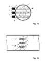
- FIGS. 1a and 1ba first embodiment of the inventive device is shown.
- An arrowindicates the flow direction of the gas.
- a plurality of position-fixed differential pressure meansare arranged in a gas pipe 1 .
- these profile elements 3have a constant cross-section in a plane perpendicular to the flow direction. In the example shown here they have the shape of a dynamic pressure profile and are therefore symmetrical.
- Each profile element 3has two opposite side surfaces 30, which abut against an inner circumferential surface 10 of the gas pipe 1.
- the profile elements 3are arranged one above the other, wherein a central profile element extends along the diameter of the gas pipe 1 and the other two extend gleichabstieri above and below parallel to this.
- Each profile element 3is connected via a bypass 4, each with a gas meter 2.
- the gas meter 2are arranged outside the gas pipe 1.
- a gas meter 2are static gas meter, preferably the aforementioned, used on a microchip gas meter for measuring the mass or energy flow. For example, they have a CMOS chip. These gas meters measure the gas flow by means of thermal measuring methods. Preferably, all gas meters are constructed identically and have the same measuring range and measuring sensitivity. In high-pressure applications with pressures of up to 50 bar, the gas sensors of the gas meters are arranged in a housing.
- bypass linesare provided on both sides of the gas sensor with shut-off valves to allow replacement of the sensor without the main gas supply must be interrupted.
- Each profile element 3has an end face 31, which is arranged at the front in the flow direction. This end face 31 is penetrated by inlet openings 32.
- the inlet openings 32are distributed equidistantly over the entire width of the end face 32 and thus over the entire width of the respective pipe segment. In another variant, they are distributed so that they allow for optimal averaging.
- the inlet openings 32open into a common feed channel 33, which is connected to a first arm of the bypass 4.
- the gas meterfurther comprises evaluation electronics with means for the weighted averaging of the measured values of the individual gas meters.
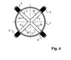
- each profile element 3has a feed and a removal channel 33, 35, which extend at least approximately from a central axis 11 of the tube 1 outwards to the tube jacket and in turn are connected to a common bypass 4 and an associated gas meter 2.
- This arrangementhas the advantage that it is rotationally symmetrical and thus provides an optimum average or integration value of the airfoil.
- FIGS. 3a and 3bhave the profile elements 3 in the form of buoyancy profiles. They are thus asymmetrically shaped and essentially correspond to an aircraft wing profile.
- the inlet openings 32are now arranged on the underside 37 of the profile element 3 and the outlet openings 34 on the top 36.
- the inlet openings 32have first connection channels 38 to the inlet channel 33, which are directed obliquely backwards in the flow direction.
- the outlet openings 34are connected via second connecting channels 39 with the Weglimkanal 35, wherein the second connecting channels 39 are directed obliquely forward.
- three profile elements 3are present, which are arranged one above the other and abut with their lateral surfaces 30 on the inner circumferential surface 10 of the gas pipe 1.
- Buoyancy profile elements 3present, which are arranged to a cross. Each outer end of the profile elements 3 is connected to a bypass 4 and a gas meter 2.
- buoyancy profile elements 3Even when buoyancy profile elements 3 are used, the pressure difference necessary for the measurement is generated by the different flow velocities on the profile top side 36 and profile bottom side 37.
- the advantage of this profile elements 3is that dirt particles that are carried in the gas stream, do not get into the feed channels 33 and the gas meter 2 are thus better protected against any contamination.
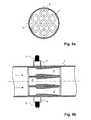
- a fifth embodimentaccording to the FIGS. 5a and 5b are the differential pressure Venturi tubes 3 ', which are arranged in the gas pipe 1.
- the Venturi tubes 3 'have inlet and outlet openings, which form the inputs and outputs of bypasses 4.
- Each bypass 4is assigned a gas meter 2 arranged outside the gas pipe 1 and a Venturi pipe 3 '.
- the gas pipe 1is thus divided into several smaller measuring units with smaller diameters.
- the measured values determined by the individual gas meter 2can be integrated into a flow profile of the entire cross section of the gas pipe 1 or to a total flow rate.
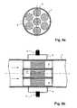
- the differential pressure means in the embodiment according to the Figures 6a and 6bare tube bundles 3 '', which are arranged in the gas pipe 1. Each connected to a gas meter 2 bypass 4 is in turn associated with a tube bundle 3 ''.
- the tube bundles 3 ''can, as shown here, be formed by tubular sections with a round cross-section. But they can also consist of pipe sections with a honeycomb or a different shaped cross-section. Again, the cross section of the gas pipe 1 divided into subregions, so that the flow profile or the entire flow rate from the individual partial measurements can be integrated.
- the device according to the inventionenables the use of low-cost, low-wear, static gas meters based on microchip for industrial installations and for large pipe diameters, without the measurement accuracy being reduced.
Landscapes
- Physics & Mathematics (AREA)
- Fluid Mechanics (AREA)
- General Physics & Mathematics (AREA)
- Measuring Volume Flow (AREA)
- Sampling And Sample Adjustment (AREA)
Abstract
Description
Translated fromGermanDie Erfindung bezieht sich auf das Gebiet der Gasmeter, insbesondere der industriellen Gasmeter. Sie bezieht sich auf eine Vorrichtung zur Messung eines Gasverbrauchs gemäss Oberbegriff des Patentanspruches 1. Die Vorrichtung eignet sich insbesondere zur Messung eines Gasflusses in einem Rohr mit einem grossen Durchmesser.The invention relates to the field of gas meters, in particular industrial gas meters. It relates to a device for measuring a gas consumption according to the preamble of
Zur industriellen Gasdurchflussmessung werden im allgemeinen Turbinen-, Coriolis-, Differenzdruck und Ultraschall-Gasmeter eingesetzt. Diese Gasmeter müssen hohen Anforderungen an mechanische Präzision genügen und benötigen zum Teil eine aufwendige elektronische Auswertung. Im Haushalt- und Kleingewerbereich haben sich die Balgengaszähler durchgesetzt. Diese sind jedoch ungenau und zudem ziemlich gross.Turbine, Coriolis, differential pressure and ultrasonic gas meters are generally used for industrial gas flow measurement. These gas meters must meet high demands on mechanical precision and sometimes require a complex electronic evaluation. In household and small businesses, the diaphragm gas meters have prevailed. These are inaccurate and also quite large.
Des weiteren wurde für den Haushalt- und Kleingewerbebereich vorgeschlagen, auf Mikrochips basierende Gasmeter einzusetzen, welche einen Massen- oder einen Energiefluss messen. Diese Gasmeter sind in einem Bypass zu einem Gasrohr angeordnet, wobei das Gasrohr in diesem Bereich eine Verjüngung aufweist, um die für die Messung notwendige Druckdifferenz respektive Strömung im Bypass zu erzeugen. Zur Messung des Massen- bzw. Energieflusses wird im wesentlichen das Gas über ein Heizelement des Gasmeters geleitet, wobei die Temperaturdifferenz des Gases vor und nach Überströmen des Heizelementes bestimmt wird. Diese Gasmeter weisen mehrere Vorteile auf: sie sind relativ klein, kostengünstig herstellbar und weisen trotzdem eine relativ hohe Messgenauigkeit mit einem maximalen Fehler von 1% und einen grossen Messbereich mit einem Verhältnis von bis zu 1000:1 auf. Da sie keine beweglichen Teile besitzen, also statische Gasmeter sind, arbeiten sie zudem praktisch verschleissfrei.Furthermore, it has been proposed for the household and small commercial sector to use microchip-based gas meters which measure a mass or energy flow. This gas meter are arranged in a bypass to a gas pipe, wherein the gas pipe in this area has a taper in order to generate the necessary for the measurement of pressure difference or flow in the bypass. To measure the mass or energy flow, the gas is essentially passed through a heating element of the gas meter, wherein the temperature difference of the gas is determined before and after overflow of the heating element. These gas meters have several advantages: they are relatively small, inexpensive to produce and yet have a relatively high accuracy with a maximum error of 1% and a large measuring range with a ratio of up to 1000: 1 on. Since they have no moving parts, so they are static gas meters, they also work virtually wear-free.
Diese Mikrochip-Gasmeter haben sich für kleine Rohrdurchmesser bewährt. Bei industrielle Gasleitungen tritt jedoch das Problem auf, dass die Rohrdurchmesser bis zu 200 mm betragen können. Dies hat zur Folge, dass ein das Rohr durchströmendes Gas ein stark asymmetrisches, undefiniertes Strömungsprofil aufweist. Dadurch lässt sich mittels des Gasmeters nicht das gesamte Strömungsprofil erfassen, die Messung des Durchflusses wird verfälscht und die Messgenauigkeit massiv beeinträchtigt. Gerade bei derartig grossen Gasleitungen ist jedoch eine Messgenauigkeit von 0.1 - 0.2 % notwendig, um den Gasbezug verbrauchergerecht zu ermitteln und abzurechnen.These microchip gas meters have proven themselves for small pipe diameters. In industrial gas lines, however, the problem arises that the pipe diameter can be up to 200 mm. This has the consequence that a gas flowing through the pipe has a strongly asymmetrical, undefined flow profile. As a result, the entire flow profile can not be detected by means of the gas meter, the measurement of the flow is falsified and the measuring accuracy is massively impaired. Especially with such large gas lines, however, a measurement accuracy of 0.1 - 0.2% is necessary in order to determine the consumption of gas in a way that suits the consumer's needs.
Es ist aus US-A-5'596'152 bekannt, in ein Gasrohr einen Strömungs-Gleichrichter einzubauen, um das Strömungsprofil vor einem Turbinen-Gasmeter zu glätten. Dieser Strömungs-Gleichrichter besteht aus einer Platte mit mehreren kleinen Öffnungen, welche so bemessen und angeordnet sind, dass das Strömungsprofil nach Durchfluss der Platte annähernd gleichmässig ist.It is known from US-A-5'596'152 to incorporate into a gas tube a flow rectifier to smooth the airfoil in front of a turbine gas meter. This flow rectifier consists of a plate with several small openings, which are sized and arranged so that the flow profile is approximately uniform after flow of the plate.
Es ist Aufgabe der Erfindung, eine Vorrichtung zur Messung eines Gasverbrauchs zu schaffen, welche auch bei Gasrohren mit grossen Durchmessern einsetzbar ist.It is an object of the invention to provide a device for measuring a gas consumption, which can also be used in gas pipes with large diameters.
Diese Aufgabe löst eine Vorrichtung mit den Merkmalen des Patentanspruches 1.This object is achieved by a device having the features of
Erfindungsgemäss sind im Gasrohr, verteilt über dessen Querschnitt, mehrere Differenzdruckmittel angeordnet, welchen über Bypässe mit dem Gasrohr verbundene Gasmeter zugeordnet sind.According to the invention, a plurality of differential pressure means are arranged in the gas pipe, distributed over the cross section, which are associated with bypasses connected to the gas pipe gas meter.
Durch die mehrfache Messung des Durchflusses mittels der Gasmeter lässt sich das Strömungsprofil mitteln beziehungsweise aufintegrieren. Dadurch lässt sich der Durchfluss auch bei asymmetrischen Strömungsprofilen mit einer relativ hohen Messgenauigkeit bestimmen.By repeatedly measuring the flow using the gas meter, the flow profile can be averaged or integrated. This allows the flow to be determined even with asymmetrical flow profiles with a relatively high measuring accuracy.
In einer bevorzugten Ausführungsform sind die Differenzdruckmittel Profilelemente, welche mehrere Ein- und Auslassöffnungen aufweisen, die jeweils mit einem einzigen Bypass und einem Gasmeter verbunden sind. Dadurch wird eine Mittelung des Strömungsprofils erzielt.In a preferred embodiment, the differential pressure means are profile elements, which have a plurality of inlet and outlet openings, which are each connected to a single bypass and a gas meter. As a result, an averaging of the airfoil is achieved.
In einer anderen bevorzugten Ausführungsform sind die Differenzdruckmittel Rohrbündel oder Venturirohre, welche eine Integration des Strömungsprofils ermöglichen.In another preferred embodiment, the differential pressure means are tube bundles or venturi tubes which allow integration of the airfoil.
Weitere vorteilhafte Ausführungsformen gehen aus den abhängigen Patentansprüchen hervor.Further advantageous embodiments will become apparent from the dependent claims.
Im folgenden wird der Erfindungsgegenstand anhand von bevorzugten Ausführungsbeispielen, welche in der beiliegenden Zeichnung dargestellt sind, erläutert. Es zeigen:
- Figur 1a
- einen Querschnitt durch ein Gasrohr mit einer erfindungsgemässen Vorrichtung gemäss einer ersten Ausführungsform;
- Figur 1b
- einen Längsschnitt durch die Ausführungsform gemäss
Figur 1a ;
- Figur 2a
- einen Querschnitt durch eine zweite Ausführungsform;
- Figur 2b
- einen Längsschnitt durch die Ausführungsform gemäss
Figur 2a ;
- Figur 3a
- einen Querschnitt durch eine dritte Ausführungsform;
- Figur 3b
- einen Längsschnitt durch die Ausführungsform gemäss
Figur 3a ;
Figur 4- einen Querschnitt durch eine vierte Ausführungsform;
- Figur 5a
- einen Querschnitt durch eine fünfte Ausführungsform;
- Figur 5b
- einen Längsschnitt durch die Ausführungsform gemäss
Figur 5a ;
- Figur 6a
- einen Querschnitt durch eine sechste Ausführungsform und
- Figur 6b
- einen Längsschnitt durch die Ausführungsform gemäss
Figur 6a .
- FIG. 1a
- a cross section through a gas pipe with an inventive device according to a first embodiment;
- FIG. 1b
- a longitudinal section through the embodiment according to
FIG. 1a ;
- FIG. 2a
- a cross section through a second embodiment;
- FIG. 2b
- a longitudinal section through the embodiment according to
FIG. 2a ;
- FIG. 3a
- a cross section through a third embodiment;
- FIG. 3b
- a longitudinal section through the embodiment according to
FIG. 3a ;
- FIG. 4
- a cross section through a fourth embodiment;
- FIG. 5a
- a cross section through a fifth embodiment;
- FIG. 5b
- a longitudinal section through the embodiment according to
FIG. 5a ;
- FIG. 6a
- a cross-section through a sixth embodiment and
- FIG. 6b
- a longitudinal section through the embodiment according to
FIG. 6a ,
In den
Vorzugsweise sind die Bypassleitungen beidseitig des Gassensors mit Absperrhahnen versehen, um ein Auswechseln des Sensors zu ermöglichen, ohne dass die Hauptgaszufuhr unterbrochen werden muss.Preferably, the bypass lines are provided on both sides of the gas sensor with shut-off valves to allow replacement of the sensor without the main gas supply must be interrupted.
Jedes Profilelement 3 weist eine Stirnfläche 31 auf, welche in Strömungsrichtung vorne angeordnet ist. Diese Stirnfläche 31 ist von Einlassöffnungen 32 durchsetzt. In einer Variante sind die Einlassöffnungen 32 gleichabständig über die gesamte Breite der Stirnfläche 32 und somit über die gesamte Breite des jeweiligen Rohrsegmentes verteilt. In einer andere Variante sind sie so verteilt, dass sie eine optimale Mittelung ermöglichen. Die Einlassöffnungen 32 münden in einen gemeinsamen Zuführkanal 33, welcher mit einem ersten Arm des Bypasses 4 verbunden ist.Each
An der Ober- und Unterseite 36,37 des Profilelementes 3 sind Auslassöffnungen 34 angeordnet, welche ebenfalls in einen gemeinsamen Kanal, den Wegführkanal 35, münden. Dieser Wegführkanal 35 ist mit einem zweiten Arm des Bypasses 4 verbunden.At the top and bottom 36,37 of the
Ist das Rohr 1 gasdurchströmt, so staut sich das Gas an den Stirnflächen 31 der Profilelemente 3. Derjenige Anteil des Gases, welcher die Profilelemente an deren Oberseite 36 überströmt, weist eine erhöhte Strömungsgeschwindigkeit auf. Diese Beschleunigung bewirkt eine zur Messung notwendige Druckdifferenz zwischen den Einlassöffnungen 32 und den Auslassöffnungen 34. Ein Teil des Gases wird durch die Einlassöffnungen 32 über den Zuführkanal 33 und dem Bypass 4 zum Gasmeter 2 geleitet und strömt durch den Bypass 4 über den Wegführkanal 35 und die Austrittsöffnungen 34 zurück in das Rohr 1. Anhand dieses Teilstroms wird der Durchfluss bestimmt. Da die Einlassöffnungen 32 über den Rohrquerschnitt verteilt angeordnet sind, stellt dieser Teilstrom eine repräsentative Mittelung des Strömungsprofils entlang des Profilelementes 3 dar. Durch die Verwendung von mehreren Profilelementen 3 lässt sich zudem das Strömungsprofil über den gesamten Querschnitt integrieren. Das Gasmeter umfasst ferner eine Auswerteelektronik mit Mitteln zur gewichteten Mittelung der Messwerte der einzelnen Gasmeter.If the
Wie in den
In einer dritten Ausführungsform gemäss den
Im hier dargestellten Beispiel sind wiederum drei Profilelemente 3 vorhanden, welche übereinander angeordnet sind und mit ihren seitlichen Flächen 30 an der inneren Mantelfläche 10 des Gasrohres 1 anliegen.In the example shown here again three
In der in der
Auch bei der Verwendung von Auftriebs-Profilelementen 3 wird der zur Messung notwendige Druckunterschied durch die unterschiedlichen Strömungsgeschwindigkeiten an der Profiloberseite 36 und Profilunterseite 37 erzeugt. Der Vorteil dieser Profilelemente 3 liegt darin, dass Schmutzpartikel, welche im Gasstrom mitgetragen werden, nicht in die Zuführkanäle 33 gelangen und die Gasmeter 2 somit besser gegen allfällige Verschmutzung geschützt sind.Even when
In einer fünften Ausführungsform gemäss den
Die Differenzdruckmittel in der Ausführungsform gemäss den
Die erfindungsgemässe Vorrichtung ermöglicht die Verwendung von kostengünstigen, verschleissarmen, statischen Gasmetern auf Mikrochip-Basis für industrielle Anlagen und für grosse Rohrdurchmesser, ohne dass die Messgenauigkeit vermindert wird.The device according to the invention enables the use of low-cost, low-wear, static gas meters based on microchip for industrial installations and for large pipe diameters, without the measurement accuracy being reduced.
- 11
- Gasrohrgas pipe
- 1010
- innere Mantelflächeinner jacket surface
- 1111
- Mittelachsecentral axis
- 22
- Gasmetergas meters
- 33
- Profilelementeprofile elements
- 3'3 '
- Venturirohreventuri tubes
- 3''3 ''
- Rohrbündeltube bundle
- 3030
- Seitenflächeside surface
- 3131
- Stirnflächeface
- 3232
- Einlassöffnungeninlets
- 3333
- Zuführkanalfeed
- 3434
- Auslassöffnungenoutlet
- 3535
- WegführkanalWegführkanal
- 3636
- Oberseitetop
- 3737
- Unterseitebottom
- 3838
- Erster VerbindungskanalFirst connection channel
- 3939
- Zweiter VerbindungskanalSecond connection channel
- 44
- Bypassbypass
Claims (10)
- An apparatus for measuring gas consumption with at least one gas meter (2), wherein the at least one gas meter (2) is arranged in a by-pass (4) to a gas pipe (1) and wherein a differential-pressure means (3, 3', 3"), which is fixed in position and which is associated with the at least one gas meter, is arranged in the gas pipe (1),characterized in that a plurality of differential-pressure means (3, 3', 3") are present which are arranged distributed over a cross-sectional face of the gas pipe (1), wherein each differential-pressure means (3, 3', 3") has an inlet opening and an outlet opening and each differential-pressure means is connected to a gas meter (2) arranged in a by-pass (4), and means for the weighted averaging of measurement values of the individual gas meters are present.
- An apparatus according to Claim 1,characterized in that the differential-pressure means are profile elements (3), and a supply duct (33) and a removal duct (35) are present next to the inlet openings (32) and the outlet openings (34) inside each profile element (3), wherein the supply duct (33) connects the inlet openings (32) to the by-pass (4) and the removal duct (35) connects the by-pass (4) to the outlet openings (34).
- An apparatus according to Claim 2,characterized in that the profile elements (3) have two opposite lateral faces (30) which rest against an internal surface area (10) of the gas pipe (1).
- An apparatus according to Claim 2,characterized in that the profile elements (3) have a longitudinal section in the form of a back-pressure profile, wherein the inlet openings (32) are arranged at the front in the flow direction of the gas and the outlet openings (34) are arranged on a surface (36) and an underside (37) of the profile element (3) at least approximately in a plane at a right angle to the flow direction.
- An apparatus according to Claim 2,characterized in that the profile elements (3) have a longitudinal section in the form of an up-lift profile, wherein the inlet openings (32) are arranged on an underside (37) of the profile element (3) and the outlet openings (34) are arranged on a top side (36) of the profile element (3).
- An apparatus according to one of Claims 4 or 5,characterized in that a plurality of profile elements (3) are arranged vertically one above the other in the gas pipe (1) in the flow direction.
- An apparatus according to one of Claims 4 or 5,characterized in that four profile elements (3) form a common cross which has four arms which rest [with] their free ends [against] an internal surface area (10) of the gas pipe (1).
- An apparatus according to Claim 1,characterized in that the differential-pressure means are Venturi tubes (3') arranged in the gas pipe (1).
- An apparatus according to Claim 1,characterized in that the differential-pressure means are bundles of tubes (3") comprising tube portions.
- An apparatus according to Claim 9,characterized in that the tube portions have a round or a honeycomb-shaped cross-section.
Priority Applications (4)
| Application Number | Priority Date | Filing Date | Title |
|---|---|---|---|
| EP01810906AEP1296118B1 (en) | 2001-09-19 | 2001-09-19 | Device to measure gas consumption |
| DE50115059TDE50115059D1 (en) | 2001-09-19 | 2001-09-19 | Device for measuring gas consumption |
| AT01810906TATE440267T1 (en) | 2001-09-19 | 2001-09-19 | DEVICE FOR MEASURING GAS CONSUMPTION |
| PCT/CH2002/000495WO2003025517A1 (en) | 2001-09-19 | 2002-09-10 | Device for measuring gas consumption |
Applications Claiming Priority (1)
| Application Number | Priority Date | Filing Date | Title |
|---|---|---|---|
| EP01810906AEP1296118B1 (en) | 2001-09-19 | 2001-09-19 | Device to measure gas consumption |
Publications (2)
| Publication Number | Publication Date |
|---|---|
| EP1296118A1 EP1296118A1 (en) | 2003-03-26 |
| EP1296118B1true EP1296118B1 (en) | 2009-08-19 |
Family
ID=8184144
Family Applications (1)
| Application Number | Title | Priority Date | Filing Date |
|---|---|---|---|
| EP01810906AExpired - LifetimeEP1296118B1 (en) | 2001-09-19 | 2001-09-19 | Device to measure gas consumption |
Country Status (4)
| Country | Link |
|---|---|
| EP (1) | EP1296118B1 (en) |
| AT (1) | ATE440267T1 (en) |
| DE (1) | DE50115059D1 (en) |
| WO (1) | WO2003025517A1 (en) |
Families Citing this family (12)
| Publication number | Priority date | Publication date | Assignee | Title |
|---|---|---|---|---|
| DE10317166A1 (en)* | 2003-04-15 | 2004-11-04 | Abb Research Ltd. | Gas meter arrangement with improved flow geometry |
| DE102004020284B4 (en)* | 2004-04-26 | 2006-12-28 | Pötter, Friedrich | Pitot tube |
| DE102004026766B4 (en)* | 2004-06-02 | 2009-01-02 | Bayerische Motoren Werke Aktiengesellschaft | Device for volume flow measurement |
| DE102005026709A1 (en)* | 2005-06-09 | 2006-12-21 | Siemens Ag | flow sensor |
| DE102007044079B4 (en)* | 2007-09-14 | 2012-02-09 | Continental Automotive Gmbh | Flow Sensor |
| DE202010007801U1 (en)* | 2010-06-10 | 2010-09-02 | Woelke Industrieelektronik Gmbh | Device for measuring the velocity of a fluid |
| JP5755185B2 (en)* | 2012-06-15 | 2015-07-29 | 日立オートモティブシステムズ株式会社 | Thermal flow meter |
| JP2014077679A (en) | 2012-10-10 | 2014-05-01 | Panasonic Corp | Flow meter |
| KR101847744B1 (en)* | 2016-12-06 | 2018-05-28 | 두산중공업 주식회사 | Aero foil flow meter |
| KR101902680B1 (en)* | 2017-01-13 | 2018-09-28 | 두산중공업 주식회사 | Aerofoil flow meter |
| KR101902679B1 (en)* | 2017-01-13 | 2018-09-28 | 두산중공업 주식회사 | Aerofoil flow meter |
| KR101902683B1 (en)* | 2017-01-18 | 2018-11-07 | 두산중공업 주식회사 | Aerofoil flow meter |
Citations (4)
| Publication number | Priority date | Publication date | Assignee | Title |
|---|---|---|---|---|
| US3803921A (en)* | 1968-07-15 | 1974-04-16 | P Dieterich | Sampling and flow measuring device |
| US4825704A (en)* | 1986-07-28 | 1989-05-02 | Yamatake-Honeywell Co., Ltd. | Fluid flow speed measuring apparatus |
| US4959990A (en)* | 1989-04-10 | 1990-10-02 | Morris Robert H | Combined mass flow/pitot tube meter |
| WO2001061282A2 (en)* | 2000-02-16 | 2001-08-23 | Honeywell International Inc. | Flow rate module and integrated flow restrictor |
Family Cites Families (4)
| Publication number | Priority date | Publication date | Assignee | Title |
|---|---|---|---|---|
| US1702274A (en)* | 1926-03-30 | 1929-02-19 | Schmidt Ernst | Determining the quantity of flowing liquids or gases |
| US5753825A (en)* | 1996-07-19 | 1998-05-19 | Brandt, Jr.; Robert O. | Velocity averaging pitot |
| FI102453B (en)* | 1997-03-17 | 1998-12-15 | Instrumentarium Oy | Improved measuring sensor and gas flow measurement system |
| US6189390B1 (en)* | 1998-04-02 | 2001-02-20 | Compliance Instrument, Inc. | Method and apparatus for measuring gas velocity or other flow characteristic |
- 2001
- 2001-09-19DEDE50115059Tpatent/DE50115059D1/ennot_activeExpired - Lifetime
- 2001-09-19ATAT01810906Tpatent/ATE440267T1/enactive
- 2001-09-19EPEP01810906Apatent/EP1296118B1/ennot_activeExpired - Lifetime
- 2002
- 2002-09-10WOPCT/CH2002/000495patent/WO2003025517A1/ennot_activeApplication Discontinuation
Patent Citations (4)
| Publication number | Priority date | Publication date | Assignee | Title |
|---|---|---|---|---|
| US3803921A (en)* | 1968-07-15 | 1974-04-16 | P Dieterich | Sampling and flow measuring device |
| US4825704A (en)* | 1986-07-28 | 1989-05-02 | Yamatake-Honeywell Co., Ltd. | Fluid flow speed measuring apparatus |
| US4959990A (en)* | 1989-04-10 | 1990-10-02 | Morris Robert H | Combined mass flow/pitot tube meter |
| WO2001061282A2 (en)* | 2000-02-16 | 2001-08-23 | Honeywell International Inc. | Flow rate module and integrated flow restrictor |
Also Published As
| Publication number | Publication date |
|---|---|
| EP1296118A1 (en) | 2003-03-26 |
| ATE440267T1 (en) | 2009-09-15 |
| WO2003025517A1 (en) | 2003-03-27 |
| DE50115059D1 (en) | 2009-10-01 |
Similar Documents
| Publication | Publication Date | Title |
|---|---|---|
| DE69331030T2 (en) | Mass Flow Meters | |
| DE3887796T2 (en) | Arrangement for flow rate measurement. | |
| EP1296118B1 (en) | Device to measure gas consumption | |
| DE3239126C2 (en) | Flowmeters for fluids | |
| DE2512644A1 (en) | DEVICE FOR MEASURING THE FLOW AND / OR VISCOSITY OF FLUIDS | |
| DE2938801A1 (en) | DEVICE FOR MEASURING THE SPEED OF A FLOW | |
| DE102019103674B4 (en) | flow measurement arrangement and fluidic arrangement | |
| EP2072972B1 (en) | Device for measuring the movement of a fluid in a pipe | |
| EP3762686A1 (en) | Fluid flow meter | |
| DE112018000081B4 (en) | FLOW METER | |
| DE10393177T5 (en) | Flow straightener | |
| DE2821711A1 (en) | METHOD AND DEVICE FOR CHECKING A FLOW METER | |
| EP3379209A1 (en) | Flow measuring device | |
| DE2405786C3 (en) | Measuring devices for gas flow measurement in gas suction lines | |
| DE102014110556B3 (en) | Device for flow measurement | |
| DE3922488C2 (en) | Air measuring device | |
| EP0431345B1 (en) | Probe for measuring pressure of a fluid flowing in a pipe | |
| DE102007023163B4 (en) | Flow meter | |
| DE3636930A1 (en) | Method and device for sensing the through-flows of fluids | |
| EP2581714A1 (en) | Method for determining an absolute flow velocity of a volume or mass flow | |
| WO2002084225A1 (en) | Vortex-frequency flowmeter | |
| DE4207043A1 (en) | Gas flow transducer for measuring pressure, flow speed or volume - has rod perpendicular to flow with inlet and outlet apertures one after other in flow direction | |
| EP0243294B1 (en) | Flow measurement arrangement | |
| DE2040593C (en) | Fluid sampling device | |
| EP4130687B1 (en) | Flow measuring system |
Legal Events
| Date | Code | Title | Description |
|---|---|---|---|
| PUAI | Public reference made under article 153(3) epc to a published international application that has entered the european phase | Free format text:ORIGINAL CODE: 0009012 | |
| AK | Designated contracting states | Kind code of ref document:A1 Designated state(s):AT BE CH CY DE DK ES FI FR GB GR IE IT LI LU MC NL PT SE TR | |
| AX | Request for extension of the european patent | Extension state:AL LT LV MK RO SI | |
| 17P | Request for examination filed | Effective date:20030912 | |
| AKX | Designation fees paid | Designated state(s):AT BE CH CY DE DK ES FI FR GB GR IE IT LI LU MC NL PT SE TR | |
| 17Q | First examination report despatched | Effective date:20050607 | |
| RAP1 | Party data changed (applicant data changed or rights of an application transferred) | Owner name:EMS-PATENT AG | |
| RIC1 | Information provided on ipc code assigned before grant | Ipc:G01F 1/684 20060101ALN20090126BHEP Ipc:G01F 1/42 20060101ALI20090126BHEP Ipc:G01F 1/46 20060101AFI20090126BHEP Ipc:G01F 1/69 20060101ALN20090126BHEP Ipc:G01F 1/44 20060101ALI20090126BHEP Ipc:G01F 5/00 20060101ALN20090126BHEP | |
| GRAP | Despatch of communication of intention to grant a patent | Free format text:ORIGINAL CODE: EPIDOSNIGR1 | |
| GRAS | Grant fee paid | Free format text:ORIGINAL CODE: EPIDOSNIGR3 | |
| GRAA | (expected) grant | Free format text:ORIGINAL CODE: 0009210 | |
| AK | Designated contracting states | Kind code of ref document:B1 Designated state(s):AT BE CH CY DE DK ES FI FR GB GR IE IT LI LU MC NL PT SE TR | |
| REG | Reference to a national code | Ref country code:GB Ref legal event code:FG4D Free format text:NOT ENGLISH | |
| REG | Reference to a national code | Ref country code:CH Ref legal event code:NV Representative=s name:TROESCH SCHEIDEGGER WERNER AG Ref country code:CH Ref legal event code:EP | |
| REG | Reference to a national code | Ref country code:IE Ref legal event code:FG4D | |
| REF | Corresponds to: | Ref document number:50115059 Country of ref document:DE Date of ref document:20091001 Kind code of ref document:P | |
| PGFP | Annual fee paid to national office [announced via postgrant information from national office to epo] | Ref country code:IE Payment date:20090921 Year of fee payment:9 | |
| PG25 | Lapsed in a contracting state [announced via postgrant information from national office to epo] | Ref country code:FI Free format text:LAPSE BECAUSE OF FAILURE TO SUBMIT A TRANSLATION OF THE DESCRIPTION OR TO PAY THE FEE WITHIN THE PRESCRIBED TIME-LIMIT Effective date:20090819 Ref country code:ES Free format text:LAPSE BECAUSE OF FAILURE TO SUBMIT A TRANSLATION OF THE DESCRIPTION OR TO PAY THE FEE WITHIN THE PRESCRIBED TIME-LIMIT Effective date:20091130 Ref country code:SE Free format text:LAPSE BECAUSE OF FAILURE TO SUBMIT A TRANSLATION OF THE DESCRIPTION OR TO PAY THE FEE WITHIN THE PRESCRIBED TIME-LIMIT Effective date:20090819 | |
| RAP2 | Party data changed (patent owner data changed or rights of a patent transferred) | Owner name:HYDROMETER GMBH | |
| REG | Reference to a national code | Ref country code:CH Ref legal event code:PUE Owner name:YDROMETER GMBH Free format text:EMS-PATENT AG#REICHENAUERSTRASSE#7013 DOMAT/EMS (CH) -TRANSFER TO- HYDROMETER GMBH#INDUSTRIESTRASSE 13#91522 ANSBACH (DE) | |
| REG | Reference to a national code | Ref country code:IE Ref legal event code:FD4D | |
| BERE | Be: lapsed | Owner name:EMS-PATENT A.G. Effective date:20090930 | |
| PG25 | Lapsed in a contracting state [announced via postgrant information from national office to epo] | Ref country code:PT Free format text:LAPSE BECAUSE OF FAILURE TO SUBMIT A TRANSLATION OF THE DESCRIPTION OR TO PAY THE FEE WITHIN THE PRESCRIBED TIME-LIMIT Effective date:20091221 Ref country code:CY Free format text:LAPSE BECAUSE OF FAILURE TO SUBMIT A TRANSLATION OF THE DESCRIPTION OR TO PAY THE FEE WITHIN THE PRESCRIBED TIME-LIMIT Effective date:20090819 | |
| NLS | Nl: assignments of ep-patents | Owner name:HYDROMETER GMBH Effective date:20100121 | |
| PG25 | Lapsed in a contracting state [announced via postgrant information from national office to epo] | Ref country code:MC Free format text:LAPSE BECAUSE OF NON-PAYMENT OF DUE FEES Effective date:20090930 Ref country code:IE Free format text:LAPSE BECAUSE OF FAILURE TO SUBMIT A TRANSLATION OF THE DESCRIPTION OR TO PAY THE FEE WITHIN THE PRESCRIBED TIME-LIMIT Effective date:20090819 Ref country code:DK Free format text:LAPSE BECAUSE OF FAILURE TO SUBMIT A TRANSLATION OF THE DESCRIPTION OR TO PAY THE FEE WITHIN THE PRESCRIBED TIME-LIMIT Effective date:20090819 | |
| REG | Reference to a national code | Ref country code:FR Ref legal event code:TP | |
| PLBE | No opposition filed within time limit | Free format text:ORIGINAL CODE: 0009261 | |
| STAA | Information on the status of an ep patent application or granted ep patent | Free format text:STATUS: NO OPPOSITION FILED WITHIN TIME LIMIT | |
| 26N | No opposition filed | Effective date:20100520 | |
| PG25 | Lapsed in a contracting state [announced via postgrant information from national office to epo] | Ref country code:BE Free format text:LAPSE BECAUSE OF NON-PAYMENT OF DUE FEES Effective date:20090930 | |
| REG | Reference to a national code | Ref country code:GB Ref legal event code:732E Free format text:REGISTERED BETWEEN 20100819 AND 20100825 | |
| PG25 | Lapsed in a contracting state [announced via postgrant information from national office to epo] | Ref country code:GR Free format text:LAPSE BECAUSE OF FAILURE TO SUBMIT A TRANSLATION OF THE DESCRIPTION OR TO PAY THE FEE WITHIN THE PRESCRIBED TIME-LIMIT Effective date:20091120 | |
| PG25 | Lapsed in a contracting state [announced via postgrant information from national office to epo] | Ref country code:LU Free format text:LAPSE BECAUSE OF NON-PAYMENT OF DUE FEES Effective date:20090919 | |
| PGFP | Annual fee paid to national office [announced via postgrant information from national office to epo] | Ref country code:CH Payment date:20110923 Year of fee payment:11 | |
| PGFP | Annual fee paid to national office [announced via postgrant information from national office to epo] | Ref country code:GB Payment date:20120920 Year of fee payment:12 | |
| PGFP | Annual fee paid to national office [announced via postgrant information from national office to epo] | Ref country code:TR Payment date:20120828 Year of fee payment:12 | |
| PGFP | Annual fee paid to national office [announced via postgrant information from national office to epo] | Ref country code:FR Payment date:20121010 Year of fee payment:12 Ref country code:NL Payment date:20120920 Year of fee payment:12 | |
| PGFP | Annual fee paid to national office [announced via postgrant information from national office to epo] | Ref country code:AT Payment date:20120912 Year of fee payment:12 | |
| REG | Reference to a national code | Ref country code:NL Ref legal event code:V1 Effective date:20140401 | |
| REG | Reference to a national code | Ref country code:CH Ref legal event code:PL | |
| REG | Reference to a national code | Ref country code:AT Ref legal event code:MM01 Ref document number:440267 Country of ref document:AT Kind code of ref document:T Effective date:20130919 | |
| GBPC | Gb: european patent ceased through non-payment of renewal fee | Effective date:20130919 | |
| REG | Reference to a national code | Ref country code:FR Ref legal event code:ST Effective date:20140530 | |
| PG25 | Lapsed in a contracting state [announced via postgrant information from national office to epo] | Ref country code:GB Free format text:LAPSE BECAUSE OF NON-PAYMENT OF DUE FEES Effective date:20130919 Ref country code:CH Free format text:LAPSE BECAUSE OF NON-PAYMENT OF DUE FEES Effective date:20130930 Ref country code:LI Free format text:LAPSE BECAUSE OF NON-PAYMENT OF DUE FEES Effective date:20130930 | |
| PG25 | Lapsed in a contracting state [announced via postgrant information from national office to epo] | Ref country code:FR Free format text:LAPSE BECAUSE OF NON-PAYMENT OF DUE FEES Effective date:20130930 Ref country code:AT Free format text:LAPSE BECAUSE OF NON-PAYMENT OF DUE FEES Effective date:20130919 Ref country code:NL Free format text:LAPSE BECAUSE OF NON-PAYMENT OF DUE FEES Effective date:20140401 | |
| REG | Reference to a national code | Ref country code:DE Ref legal event code:R082 Ref document number:50115059 Country of ref document:DE Representative=s name:PFENNING MEINIG & PARTNER GBR, DE | |
| REG | Reference to a national code | Ref country code:DE Ref legal event code:R082 Ref document number:50115059 Country of ref document:DE Representative=s name:PFENNING MEINIG & PARTNER GBR, DE Effective date:20150506 Ref country code:DE Ref legal event code:R081 Ref document number:50115059 Country of ref document:DE Owner name:DIEHL METERING GMBH, DE Free format text:FORMER OWNER: HYDROMETER GMBH, 91522 ANSBACH, DE Effective date:20150506 Ref country code:DE Ref legal event code:R082 Ref document number:50115059 Country of ref document:DE Representative=s name:PFENNING, MEINIG & PARTNER MBB PATENTANWAELTE, DE Effective date:20150506 | |
| PG25 | Lapsed in a contracting state [announced via postgrant information from national office to epo] | Ref country code:TR Free format text:LAPSE BECAUSE OF NON-PAYMENT OF DUE FEES Effective date:20130919 | |
| PGFP | Annual fee paid to national office [announced via postgrant information from national office to epo] | Ref country code:DE Payment date:20161123 Year of fee payment:16 | |
| PGFP | Annual fee paid to national office [announced via postgrant information from national office to epo] | Ref country code:IT Payment date:20170926 Year of fee payment:17 | |
| REG | Reference to a national code | Ref country code:DE Ref legal event code:R119 Ref document number:50115059 Country of ref document:DE | |
| PG25 | Lapsed in a contracting state [announced via postgrant information from national office to epo] | Ref country code:DE Free format text:LAPSE BECAUSE OF NON-PAYMENT OF DUE FEES Effective date:20180404 | |
| PG25 | Lapsed in a contracting state [announced via postgrant information from national office to epo] | Ref country code:IT Free format text:LAPSE BECAUSE OF NON-PAYMENT OF DUE FEES Effective date:20180919 |