EP1295578A2 - Medical insertion tool with slaphammer - Google Patents
Medical insertion tool with slaphammerDownload PDFInfo
- Publication number
- EP1295578A2 EP1295578A2EP02256516AEP02256516AEP1295578A2EP 1295578 A2EP1295578 A2EP 1295578A2EP 02256516 AEP02256516 AEP 02256516AEP 02256516 AEP02256516 AEP 02256516AEP 1295578 A2EP1295578 A2EP 1295578A2
- Authority
- EP
- European Patent Office
- Prior art keywords
- mass
- levers
- implant
- installation tool
- effective
- Prior art date
- Legal status (The legal status is an assumption and is not a legal conclusion. Google has not performed a legal analysis and makes no representation as to the accuracy of the status listed.)
- Withdrawn
Links
Images


Classifications
- A—HUMAN NECESSITIES
- A61—MEDICAL OR VETERINARY SCIENCE; HYGIENE
- A61F—FILTERS IMPLANTABLE INTO BLOOD VESSELS; PROSTHESES; DEVICES PROVIDING PATENCY TO, OR PREVENTING COLLAPSING OF, TUBULAR STRUCTURES OF THE BODY, e.g. STENTS; ORTHOPAEDIC, NURSING OR CONTRACEPTIVE DEVICES; FOMENTATION; TREATMENT OR PROTECTION OF EYES OR EARS; BANDAGES, DRESSINGS OR ABSORBENT PADS; FIRST-AID KITS
- A61F2/00—Filters implantable into blood vessels; Prostheses, i.e. artificial substitutes or replacements for parts of the body; Appliances for connecting them with the body; Devices providing patency to, or preventing collapsing of, tubular structures of the body, e.g. stents
- A61F2/02—Prostheses implantable into the body
- A61F2/30—Joints
- A61F2/46—Special tools for implanting artificial joints
- A61F2/4603—Special tools for implanting artificial joints for insertion or extraction of endoprosthetic joints or of accessories thereof
- A61F2/4611—Special tools for implanting artificial joints for insertion or extraction of endoprosthetic joints or of accessories thereof of spinal prostheses
- A—HUMAN NECESSITIES
- A61—MEDICAL OR VETERINARY SCIENCE; HYGIENE
- A61B—DIAGNOSIS; SURGERY; IDENTIFICATION
- A61B17/00—Surgical instruments, devices or methods
- A61B17/02—Surgical instruments, devices or methods for holding wounds open, e.g. retractors; Tractors
- A61B17/025—Joint distractors
- A61B2017/0256—Joint distractors for the spine
- A—HUMAN NECESSITIES
- A61—MEDICAL OR VETERINARY SCIENCE; HYGIENE
- A61F—FILTERS IMPLANTABLE INTO BLOOD VESSELS; PROSTHESES; DEVICES PROVIDING PATENCY TO, OR PREVENTING COLLAPSING OF, TUBULAR STRUCTURES OF THE BODY, e.g. STENTS; ORTHOPAEDIC, NURSING OR CONTRACEPTIVE DEVICES; FOMENTATION; TREATMENT OR PROTECTION OF EYES OR EARS; BANDAGES, DRESSINGS OR ABSORBENT PADS; FIRST-AID KITS
- A61F2/00—Filters implantable into blood vessels; Prostheses, i.e. artificial substitutes or replacements for parts of the body; Appliances for connecting them with the body; Devices providing patency to, or preventing collapsing of, tubular structures of the body, e.g. stents
- A61F2/02—Prostheses implantable into the body
- A61F2/30—Joints
- A61F2/44—Joints for the spine, e.g. vertebrae, spinal discs
- A61F2/442—Intervertebral or spinal discs, e.g. resilient
- A—HUMAN NECESSITIES
- A61—MEDICAL OR VETERINARY SCIENCE; HYGIENE
- A61F—FILTERS IMPLANTABLE INTO BLOOD VESSELS; PROSTHESES; DEVICES PROVIDING PATENCY TO, OR PREVENTING COLLAPSING OF, TUBULAR STRUCTURES OF THE BODY, e.g. STENTS; ORTHOPAEDIC, NURSING OR CONTRACEPTIVE DEVICES; FOMENTATION; TREATMENT OR PROTECTION OF EYES OR EARS; BANDAGES, DRESSINGS OR ABSORBENT PADS; FIRST-AID KITS
- A61F2/00—Filters implantable into blood vessels; Prostheses, i.e. artificial substitutes or replacements for parts of the body; Appliances for connecting them with the body; Devices providing patency to, or preventing collapsing of, tubular structures of the body, e.g. stents
- A61F2/02—Prostheses implantable into the body
- A61F2/30—Joints
- A61F2/46—Special tools for implanting artificial joints
- A61F2/4603—Special tools for implanting artificial joints for insertion or extraction of endoprosthetic joints or of accessories thereof
- A61F2002/4622—Special tools for implanting artificial joints for insertion or extraction of endoprosthetic joints or of accessories thereof having the shape of a forceps or a clamp
- A—HUMAN NECESSITIES
- A61—MEDICAL OR VETERINARY SCIENCE; HYGIENE
- A61F—FILTERS IMPLANTABLE INTO BLOOD VESSELS; PROSTHESES; DEVICES PROVIDING PATENCY TO, OR PREVENTING COLLAPSING OF, TUBULAR STRUCTURES OF THE BODY, e.g. STENTS; ORTHOPAEDIC, NURSING OR CONTRACEPTIVE DEVICES; FOMENTATION; TREATMENT OR PROTECTION OF EYES OR EARS; BANDAGES, DRESSINGS OR ABSORBENT PADS; FIRST-AID KITS
- A61F2/00—Filters implantable into blood vessels; Prostheses, i.e. artificial substitutes or replacements for parts of the body; Appliances for connecting them with the body; Devices providing patency to, or preventing collapsing of, tubular structures of the body, e.g. stents
- A61F2/02—Prostheses implantable into the body
- A61F2/30—Joints
- A61F2/46—Special tools for implanting artificial joints
- A61F2/4603—Special tools for implanting artificial joints for insertion or extraction of endoprosthetic joints or of accessories thereof
- A61F2002/4625—Special tools for implanting artificial joints for insertion or extraction of endoprosthetic joints or of accessories thereof with relative movement between parts of the instrument during use
- A61F2002/4627—Special tools for implanting artificial joints for insertion or extraction of endoprosthetic joints or of accessories thereof with relative movement between parts of the instrument during use with linear motion along or rotating motion about the instrument axis or the implantation direction, e.g. telescopic, along a guiding rod, screwing inside the instrument
- A—HUMAN NECESSITIES
- A61—MEDICAL OR VETERINARY SCIENCE; HYGIENE
- A61F—FILTERS IMPLANTABLE INTO BLOOD VESSELS; PROSTHESES; DEVICES PROVIDING PATENCY TO, OR PREVENTING COLLAPSING OF, TUBULAR STRUCTURES OF THE BODY, e.g. STENTS; ORTHOPAEDIC, NURSING OR CONTRACEPTIVE DEVICES; FOMENTATION; TREATMENT OR PROTECTION OF EYES OR EARS; BANDAGES, DRESSINGS OR ABSORBENT PADS; FIRST-AID KITS
- A61F2/00—Filters implantable into blood vessels; Prostheses, i.e. artificial substitutes or replacements for parts of the body; Appliances for connecting them with the body; Devices providing patency to, or preventing collapsing of, tubular structures of the body, e.g. stents
- A61F2/02—Prostheses implantable into the body
- A61F2/30—Joints
- A61F2/46—Special tools for implanting artificial joints
- A61F2/4603—Special tools for implanting artificial joints for insertion or extraction of endoprosthetic joints or of accessories thereof
- A61F2002/4625—Special tools for implanting artificial joints for insertion or extraction of endoprosthetic joints or of accessories thereof with relative movement between parts of the instrument during use
- A61F2002/4628—Special tools for implanting artificial joints for insertion or extraction of endoprosthetic joints or of accessories thereof with relative movement between parts of the instrument during use with linear motion along or rotating motion about an axis transverse to the instrument axis or to the implantation direction, e.g. clamping
- A—HUMAN NECESSITIES
- A61—MEDICAL OR VETERINARY SCIENCE; HYGIENE
- A61F—FILTERS IMPLANTABLE INTO BLOOD VESSELS; PROSTHESES; DEVICES PROVIDING PATENCY TO, OR PREVENTING COLLAPSING OF, TUBULAR STRUCTURES OF THE BODY, e.g. STENTS; ORTHOPAEDIC, NURSING OR CONTRACEPTIVE DEVICES; FOMENTATION; TREATMENT OR PROTECTION OF EYES OR EARS; BANDAGES, DRESSINGS OR ABSORBENT PADS; FIRST-AID KITS
- A61F2/00—Filters implantable into blood vessels; Prostheses, i.e. artificial substitutes or replacements for parts of the body; Appliances for connecting them with the body; Devices providing patency to, or preventing collapsing of, tubular structures of the body, e.g. stents
- A61F2/02—Prostheses implantable into the body
- A61F2/30—Joints
- A61F2/46—Special tools for implanting artificial joints
- A61F2002/4681—Special tools for implanting artificial joints by applying mechanical shocks, e.g. by hammering
- A—HUMAN NECESSITIES
- A61—MEDICAL OR VETERINARY SCIENCE; HYGIENE
- A61F—FILTERS IMPLANTABLE INTO BLOOD VESSELS; PROSTHESES; DEVICES PROVIDING PATENCY TO, OR PREVENTING COLLAPSING OF, TUBULAR STRUCTURES OF THE BODY, e.g. STENTS; ORTHOPAEDIC, NURSING OR CONTRACEPTIVE DEVICES; FOMENTATION; TREATMENT OR PROTECTION OF EYES OR EARS; BANDAGES, DRESSINGS OR ABSORBENT PADS; FIRST-AID KITS
- A61F2/00—Filters implantable into blood vessels; Prostheses, i.e. artificial substitutes or replacements for parts of the body; Appliances for connecting them with the body; Devices providing patency to, or preventing collapsing of, tubular structures of the body, e.g. stents
- A61F2/02—Prostheses implantable into the body
- A61F2/30—Joints
- A61F2/46—Special tools for implanting artificial joints
- A61F2002/4687—Mechanical guides for implantation instruments
Definitions
- the present inventionrelates to tools for inserting prostheses within the body, and more particularly to an instrument for inserting an implant between adjacent bone structures, and for subsequently removing the instrument.
- the intervertebral discis one structure prone to the degenerative changes associated with wear and tear, aging, and even misuse. Over time the collagen (protein) structure of the intervertebral disc weakens and may become structurally unsound. Additionally, the water and proteoglycan (the molecules that attract water) content decreases, thereby narrowing the space between the adjacent vertebrae, which can result in nerve root compression and pain. These changes can lead to the disc's inability to handle mechanical stress.
- spinal fusion surgeryinvolves the surgical removal of a portion or all of an intervertebral disc followed by fusion of the adjacent vertebrae.
- a prosthetic devicee.g. a fusion cage, is usually placed between the two adjacent vertebrae to fill the space left by the removed disc and to allow bone to grow between the adjacent vertebrae.
- spinal distracterse.g. spreaders
- insertion devicese.g. a spinal distracter, e.g. spreaders, and insertion devices.
- the spreaderis placed between adjacent vertebrae, and then used to pry the vertebrae apart.
- the prosthetic devicecan then be inserted, either manually or with an insertion tool, into the space to hold the adjacent vertebrae apart.
- cancellous boneis packed in and/or around the implant to promote fusion of the adjacent vertebrae.
- an installation toolfor inserting an implant, such as an artificial disc, between adjacent bone structures, and for the subsequent removal of the tool without displacement of the implant.
- an installation toolhaving a pair of opposed levers, each lever having a proximal portion and a distal portion.
- a placement elementsuch as a pusher assembly, is disposed between the levers and slidably movable between a first, proximal position and a second, distal position.
- the placement elementis effective to insert an implant between adjacent bone structures.
- the installation toolfurther includes a mass slidably disposed with respect to at least a portion of the placement element.
- the massis effective to be selectively reciprocated to apply a proximally directed force to the opposed levers, thereby removing the installation tool from the space between the adjacent bone structures.
- the position of the placement elementis maintained during reciprocation of the slidable mass, thereby preventing movement of the implant during removal of the installation tool.
- the installation toolcan include a connecting element, such as a fulcrum, disposed between the opposed levers for allowing movement of the levers with respect to each other.
- the connecting elementcan optionally include a force receiving element, such as a cylindrical body, for receiving a force applied by the mass.
- a groove and engagement elementcan be provided on the mass and force receiving element for effecting selective movement of the mass with respect to the force receiving element.
- movement of the mass between the first and second positionsis controlled and limited by a longitudinally extending groove formed in and extending over a portion of the cylindrical body, and an engagement element protruding from a portion of the slidable mass and adapted to mate with the groove.
- the force receiving elementand can optionally include a locking element for locking the mass in a stationary position, preferably the first, distal position.
- the placement elementis a pusher assembly having a pusher rod having a proximal end and a distal end.
- the proximal endcan include a handle for facilitating grasping of the pusher rod.
- the distal endcan include an engagement element for mating with a prosthesis.
- the fulcrum and the cylindrical bodyeach include a bore extending therethrough that is adapted to slidably receive the pusher rod.
- the pusher assemblycan include a pusher block mated to the distal end of the pusher rod. The pusher block is adapted to be positioned between the two levers and is selectively moveable between an initial location distal of the fulcrum and a final location adjacent the distal end of the levers.
- the present inventionprovides an installation tool that is useful for the efficient and effective placement of a prosthesis between adjacent bone structures, preferably adjacent vertebral bodies, and for the subsequent removal of the device without displacement of the prosthesis.
- the installation tool of the inventioncan be used to place other elements between vertebral bodies, or in other locations within a patient's body.
- Exemplary elements that can be placed between vertebral bodiesinclude, but are not limited to, interbody cages, fusion devices, spacers, grafts, and the like.
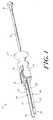
- the tool 10includes a first portion that is effective to insert a prosthesis between adjacent bone structures and a second portion, integrated with the first portion, that is effective to remove the installation portion from between the bone structures after insertion of the prosthesis.
- the second portionis commonly referred to as a slaphammer.
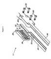
- the installation portion of tool 10generally includes a pair of opposed levers 12A, 12B, and a placement element 44 disposed between the levers 12A, 12B.
- the placement element 44is a pusher assembly.
- the levers 12A, 12Bcan be movably or pivotally mated to each other, and are effective to separate adjacent bone structures, such as adjacent vertebrae.
- a connecting element 28can be disposed between the proximal portion of the levers 12A, 12B for allowing movement of the levers 12A, 12B with respect to each other.
- the pusher assembly 44which is effective to insert a prosthesis between the adjacent bone structures, includes a pusher rod 50 slidably movable with respect to the levers.
- the pusher assembly 44can optionally include a pusher block 60 mated to the distal end of the pusher rod 50.
- the slaphammer portion of tool 10generally includes a slidable mass 82 that is effective to apply a proximally directed force to the opposed levers, thereby facilitating removal of the instrument 10 from the space between the adjacent bone structures.
- the slaphammer portioncan be adapted to apply the force directly to the levers 12A, 12B and/or the connecting element 28 or, alternatively, the tool 10 can include a force receiving element 74 (FIG. 2) adapted to receive the force applied by the slidable mass 82.
- the opposed levers 12A, 12B of the installation portion of the tool 10can have a variety of shapes and sizes, but are preferably elongate members that are mirror images of each other.
- Each lever 12A, 12Bincludes a proximal portion 14A, 14B, a distal portion 16A, 16B, an outwardly facing surface 18A, 18B, and an inwardly facing surface 20A, 20B.
- the outwardly and inwardly facing surfaces 18A, 18B, 20A, 20B of each lever 12A, 12Bare formed from two separate components, a stop member component 307A, 307B and a blade member component 308A, 308B, which are longitudinally separable from one another.
- each lever 12A, 12Bcan be formed from a single elongate member having some or all of the features disclosed herein.
- a stop member componenta person having ordinary skill in the art will appreciate that the stop member component does not need to function as a stop member.
- the blade member component 308A, 308Bforms the inwardly facing portion 20A, 20B of each lever 12A, 12B and includes a blade tip 24A, 24B to facilitate the placement of the levers 12A, 12B between adjacent bone structures.
- the outwardly facing surface 18A, 18B of each blade tip 24A, 24Bcan include a beveled or radiused surface 46 to further facilitate insertion of the levers 12A, 12B between the vertebral bodies.
- the inwardly facing surface of each blade member component 308A, 308Bcan be adapted to slidably receive a prosthesis during an installation procedure. As shown in FIG. 2, the inwardly facing surfaces 20A, 20B are substantially flattened to enable a prostheses to slide along these surfaces during installation.
- the inwardly facing surfaces 20A, 20B of the levers 12A, 12Bcan adapted to receive prosthesis having various shapes and sizes, and they can be modified to have surface features that are complementary to surface features that may be present on a prosthesis to be implanted.
- each lever 12A, 12Bcan include a rail 22A, 22B formed on one or more edges of the inwardly facing surface 20A, 20B.
- the rail 22A, 22Bis preferably formed by a portion which extends beyond the width of each lever 12A, 12B.
- the blade member component 308A, 308Bhas a width W b greater than the width W s of the stop member component 307A, 307B, thereby forming the rail 22A, 22B.
- the pusher block 60 of the pusher assembly 44can include a corresponding recess for receiving the rail 22A, 22B.
- a person having ordinary skill in the artwill appreciate that a variety of different mating elements can be provided for slidably mating the pusher block 60 and the levers 12A, 12B.
- the stop member component 307which forms the outwardly facing portion 18A, 18B of each lever 12A, 12B, can include a distal end having a stop surface 26A, 26B.
- Each stop surface 26A, 26Bwhich is substantially vertically oriented and distally facing, is adapted to abut a bone structure, such as a vertebral body, during a surgical procedure for installing of a prosthesis between adjacent bone structures.
- the length l b of the blade member component 308should be greater than the length l s of the stop member component 307 to allow the blade tips 24A, 24B to be inserted between adjacent bone structures, and the stop surface 26A, 26B to abut the exterior sides of the adjacent bone structures.
- each levercan include a protruding member extending outwardly in a direction perpendicular to the longitudinal axis L of the instrument 10.
- the tool 10can include a feature for permitting selective adjustment of the blade tip length (i.e., the distance between the distal end of blade tips 24A, 24B and stop surface 26A, 26B).
- the tool 10can include a junction box 309 which houses and secures components 307 and 308.
- a proximal portion of the stop member component 307which mates with the inner surface of the cover 320 of the junction box 309, includes a series of grooves 310 separated by raised ridges 311.
- the abutting, inner surface of the cover 320 of the junction box 309includes grooves and ridges 310, 311 as well.
- the cover 320is secured to levers 12A, 12B by suitable fasteners, such as screws 322.
- Biasing elementssuch as compression springs (not shown) are preferably used to bias the junction box to a position such that the grooves and ridges 310, 311 of the cover 320 and the stop member component 307 mate with and remain firmly secured to one another.
- Suitable indicia 325may be present on the stop member component 307 to indicated the position of the stop member component 307 with respect to the blade member component 308.
- FIG. 3only illustrates the configuration of one of the levers, it is understood that the same construction can be used for both levers.
- the result of the selective adjustability of the levers 12A, 12Bis shown in FIGS. 4A and 4B, in which the length of the blade tip 24A is greater in FIG. 4A than in FIG. 4B.
- the length of the levers 12A, 12Bcan vary, the length l b of each blade member component 308A, 308B is preferably between about 200 and 400 mm, and the length l s of each stop member component 307A, 307B is preferably about 20 mm less than the length of each blade member component 308A, 308B.
- the width of the levers 12A, 12Bcan also vary depending on the intended use, but preferably the width W b of each blade member component 308A, 308B is between about 5 and 10 mm, and the width W s of each stop member component 307A, 307B is about 4 mm less than the width W b of each blade member component 308A, 308B.
- the proximal portion 14A, 14B of each lever 12A, 12Bcan be mated by a connecting element, such as a fulcrum 28, which allows relative movement of the levers 12A, 12B in a pivoting manner.
- the levers 12A, 12Bare movable between an open position, as shown in FIG. 1, and a closed position (not shown) wherein the distal portions 16A, 16B of each lever 12A, 12B are in physical contact with each other.
- the fulcrum 28is disposed between the proximal portion 14A, 14B of each lever 12A, 12B, and is substantially a block-like object having a central bore 30 extending longitudinally therethrough. While there is no absolute top or bottom of the tool 10, for ease of reference the fulcrum 28 and other components of the tool 10 will be described herein with reference to the illustrated orientation.
- the fulcrum 28includes a top surface 34, a bottom surface 36, a core section 38 having a distal end surface 40 and a proximal end surface 42, and opposed recesses 48 (not shown) defined by the top and bottom surfaces 34, 36.
- the core section 38 of the fulcrum 28preferably includes a central bore 30 extending between the distal end surface 40 and the proximal end surface 42.
- the bore 30is adapted to slidably receive a portion of the pusher assembly 44.
- the opposed recesses 48are adapted to seat the proximal ends 14A, 14B of the opposed levers 12A, 12B.
- the fulcrum 28includes a biasing element (not shown), such as a coil or spring, disposed within each recess 48 and adapted to provide movement of the proximal end 14A, 14B of the levers 12A, 12B with respect to each other and with respect to the fulcrum 28.
- a biasing elementsuch as a coil or spring
- the fulcrum 28may assume virtually any size and shape that is able to render it effective to separate the proximal portion 14A, 14B of the levers 12A, 12B, while allowing the distal portion 16A, 16B of the levers 12A, 12B to be moved between the open and closed positions.
- the tool 10further includes a placement element slidably disposed with respect to the fulcrum 28 and the levers 12A, 12B, and adapted to insert a prosthesis between adjacent bone structures.
- the placement elementcan have a variety of different structures and can employ a variety of different mechanisms for inserting or otherwise placing an implant between adjacent bone structures.
- the placement element 44can be include a trigger actuated plunger that pushes against a piston to insert the implant between adjacent bone structures.
- Other types of placement elements 44can include, for example, those which employ a threaded advancement mechanism, a pulley assembly, or a spring mechanism for inserting an implant between adjacent bone structures.
- the placement elementis a pusher assembly 44 including a pusher rod 50 having a proximal end 52 and a distal end 54, and, optionally, a pusher block 60 mated to the distal end 54 of the pusher rod 50.
- the pusher assembly 18is slidably movable between a first, proximal position shown in FIG. 1, and a second, distal position shown in FIG. 2.
- the pusher rod 50is utilized to actuate the pusher block 60, and is preferably an elongate, cylindrical member.
- the proximal end 52can include a gripping element, such as a handle 56 to facilitate grasping of the pusher assembly 44.
- the distal end 54 of the pusher rod 50preferably includes a threaded region 58 for connecting the pusher rod 50 to the pusher block 60.
- the rod 50is adapted to be positioned between the levers 12A, 12B such that it extends through the central bore 30 in the fulcrum 28, as shown in FIG. 2.
- the threaded region 58 of the rod 50mates with a threaded blind bore 70 formed in the pusher block 60.
- the rod 50positively engages the pusher block 60 so that forward and rearward movement of the pusher rod 50 will directly move the pusher block 60.
- the distal end 54 of the pusher rod 50can be adapted to engage or abut the proximal surface of a prosthesis to be implanted.
- the threaded region 58 of the rod 50can mate with a threaded blind bore formed in the prosthesis (not shown).
- Pusher block 60may be in the form of a substantially block-like object having side walls 62A, 62B that define opposed recesses 64A, 64B.
- the inwardly facing portion of each side wall 62A, 62Bcan include a guide post 49A, 49B, 49C, 49D that extends into the recess 64A, 64B for mating the pusher block 60 with the levers 12A, 12B.
- the rails 22A, 22B of each lever 12A, 12Bextend between the guide posts 49 and the inner-most wall of each recess 64A, 64B, thereby preventing the levers 12A, 12B from separating.
- the proximally facing wall (not shown) of the pusher block 60may include a blind bore 70 having internal threads 71 adapted to mate with complimentary threads 58 formed on a distal end 54 of the pusher rod 50.
- the distally facing wall 66 of the pusher block 60can include a recessed region 104 that is adapted to nest a prosthesis (not shown). As illustrated in FIG. 8B, the recessed region 104 has dimensions that enable a prosthesis, e.g. an artificial disc 204, to fit loosely therein.
- a prosthesise.g. an artificial disc 204
- the recessed area 104should have dimensions slightly greater than the dimensions of the prosthesis 204 so as to avoid a frictional fit that may inhibit free release of the prosthesis from the tool.
- the pusher blockmay assume a variety of sizes and geometries that facilitate engagement with a variety of different prostheses.
- the tool 10further includes an integrated slaphammer portion 72 for removing the tool 10 after a prosthesis is positioned between adjacent bone structures.
- the slaphammer portion of tool 10can be used with virtually any type of installation tool, and is not limited to the installation portion of tool 10 described herein.
- the slaphammer 72includes a slidable mass 82 and, optionally, a force receiving element 74.
- the force receiving element 74can have any shape or size, and can be formed integrally with or mated to the fulcrum 28 and/or the levers 12A, 12B.
- the force receiving element 74is in the shape of a cylindrical body having a proximal end 76, a distal end 78, and a central bore 80 extending therethrough.
- the distal end 78is adhesively or mechanically mated to the proximal end surface 42 of the fulcrum 28 (FIG. 2).
- the force receiving element 74can have any length l f , but should have a length l f sufficient to allow slidable movement of the mass 82 with respect to the force receiving element 74. Moreover, the length l f should be sufficient to allow a force to be applied by the mass 82 to the force receiving element 74 to move the force receiving element 74 in a proximal direction. Preferably, the length l f is between about 50 and 100 mm.
- the diameter d f of the central bore 80 in the cylindrical body 74should be sufficient to allow slidable movement of the pusher rod 50 therethrough, and is preferably between about 5 and 10 mm.
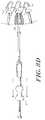
- the mass 82shown in FIG. 7B, includes a proximal end 84, a distal end 86, and a central bore or lumen 88 extending therebetween and adapted to receive the force receiving element 74.
- the mass 82is slidably disposed around the force receiving element 74 and movable between a first, proximal position (shown in FIGS. 2 and 7A), and a second, distal position (shown in FIG. 1).
- the mass 82can have any shape and size, but is preferably generally cylindrical and has a shape adapted to facilitate grasping of the mass 82 to effect movement between the first and second positions.
- the mass 82should have a length l m substantially the same as the length l f of the force receiving element 74, and preferably has a length l m between about 50 and 100 mm.
- the central bore or lumen 88 of the mass 82should have a diameter d m greater than the diameter d f of the central bore 80.
- the diameter d mis adapted to allow slidable movement of the mass 82 with respect to the force receiving element 74, and is preferably between about 6 and 11 mm.
- the mass 82can have any weight, but preferably has a weight between about 2 and 10 kg.
- FIGS. 1, 2, 7A, and 7Billustrate the mass 82 slidably mated to the force receiving element 74
- a person having ordinary skill in the artwill appreciate that a variety of different embodiments can be used to form the slaphammer 72.
- the fulcrum 28 and/or the levers 12A, 12Bcan form the force receiving element 74, and a mass can be slidably mated directly to the fulcrum 28 and/or levers 12A, 12B.
- the slaphammer 72can include an engagement member disposed between the force receiving element 74 and the slidable mass 82 for limiting movement of the mass 82 with respect to the force receiving element 74.
- the engagement memberis preferably an elongate track or groove formed in or on one of the mass 82 and the force receiving element 74, and a corresponding protruding member formed in or on the other one of the mass 82 and the force receiving element 74.
- the protruding memberis adapted to mate with the groove to effect selective movement of the mass 82 with respect to the force receiving element 74.
- the groove 90is formed in the force receiving element 74 and extends parallel to the longitudinal axis L of the instrument 10.
- the groove 90preferably extends along a substantial portion of the force receiving element 74 and includes a proximal end 94 and a distal end 92.
- a corresponding protruding membershown in FIG. 7B, is disposed within the central lumen 88 of the slidable mass 82 and is adapted to be slidably disposed within the groove 90.
- the protruding member 100e.g.
- a pin membershould be positioned to radially extend within the lumen 88 of the slidable mass 82 such that the protruding member 100 extends into the groove 90 when the mass 82 is slidably disposed around the force receiving element 74.
- the groove 90is effective to limit movement of the mass 82 between the proximal position (FIG. 1) and the distal position (FIG. 2).
- the proximal end 94 of the groove 90is adapted to receive a force applied by the mass 82. The force is the result of the protruding member 100 impacting the proximal end surface 94 of the groove 90 each time the mass 82 is moved proximally.
- the slaphammer 72can optionally include a locking feature for preventing movement of the mass 82 with respect to the force receiving element 74.
- a locking feature 96shown in FIG. 7A is a substantially L-shaped groove 96 extending radially around a portion of the force receiving element 74 and in communication with the distal end 92 of the groove 90.
- the slidable mass 82is rotated in the first distal position (FIG. 1), and then moved proximally to position the pin member 100 within the locking feature 96, thereby preventing movement of the mass 82 to the second distal position (FIG. 2).
- the proximally-directed portion 96A of the L-shaped groove 96can include a positive engagement feature adapted to bias or engage the pin member 100.
- the mass 82is moved distally and rotated in the opposite direction to remove the mass 82 from the locked position.
- a person having ordinary skill in the artwill readily appreciate that a variety of different locking elements can be provided for preventing movement of the mass 82 with respect to the force receiving element 74.
- FIGS. 1 and 8A-8Dsequentially illustrate the use of tool 10 for the installation of a prosthesis 204.
- the toolis first assembled, as shown in FIG. 1, with the pusher assembly 44 positioned in the proximal position and the slidable mass 82 positioned in the distal, locked position.
- the prosthesis 204is placed against the distal end surface 66 of the pusher block 60 between the levers 12A, 12B.
- the blade tips 24A, 24BWith the blade tips 24A, 24B in the closed position, as shown in FIG. 8A, the blade tips 24A, 24B are wedged between adjacent vertebral bodies 200A, 200B to effect slight separation between the vertebrae.
- the blade tips 24A, 24Bshould be fully inserted between the vertebral bodies 200A, 200B, as shown in FIG. 8A, so as to enable the stop surface 26A, 26B of each lever 12A, 12B to abut the posterior side 208A, 208B of the vertebral bodies 200A, 200B.
- the pusher rod 50is then advanced forward, causing distal movement of the pusher block 60 and artificial prosthesis 204.
- the forward or distal movement of pusher block 60 and the artificial prosthesis 204also causes further separation of the blade tips 24A, 24B and thus further separation of the vertebral bodies 200A, 200B.
- Advancement of the pusher block 60 and the artificial prosthesis 204continues until, as shown in FIG. 8C, the prosthesis 204 is properly installed between the adjacent vertebral bodies 200A, 200B.
- FIGS. 8B and 8Cillustrate that at all times separation of the vertebral bodies is only effected to the extent necessary to insert the prosthesis 204. Excessive distraction or separation of the vertebral bodies does not occur because the separation of vertical bodies is caused by the prosthesis and is controlled by the prosthesis thickness dimensions.
- the slidable mass 82is rotated to remove the mass 82 from the locked position. While the pusher assembly 44 is held against the prosthesis 204 and the adjacent vertebrae 200A, 200B (FIGS. 8B and 8C), the mass 82 is selectively reciprocated to apply a proximally directed force to the force receiving element 74, thereby applying a proximally directed force to the fulcrum 28 and the opposed levers 12A, 12B. The force is a result of the protruding member 100 impacting the proximal end surface 94 of the groove 90 each time the mass 82 is moved proximally. Movement of the mass 82 is effected until the levers 12A, 12B are removed from the vertebral space.
Landscapes
- Health & Medical Sciences (AREA)
- Transplantation (AREA)
- Engineering & Computer Science (AREA)
- Biomedical Technology (AREA)
- Orthopedic Medicine & Surgery (AREA)
- Oral & Maxillofacial Surgery (AREA)
- Physical Education & Sports Medicine (AREA)
- Cardiology (AREA)
- Neurology (AREA)
- Heart & Thoracic Surgery (AREA)
- Vascular Medicine (AREA)
- Life Sciences & Earth Sciences (AREA)
- Animal Behavior & Ethology (AREA)
- General Health & Medical Sciences (AREA)
- Public Health (AREA)
- Veterinary Medicine (AREA)
- Prostheses (AREA)
- Surgical Instruments (AREA)
Abstract
Description
The present invention relates to tools for inserting prostheses within the body, andmore particularly to an instrument for inserting an implant between adjacent bone structures,and for subsequently removing the instrument.
Degenerative changes in the spine can cause the loss of normal structure and/orfunction. The intervertebral disc is one structure prone to the degenerative changesassociated with wear and tear, aging, and even misuse. Over time the collagen (protein)structure of the intervertebral disc weakens and may become structurally unsound.Additionally, the water and proteoglycan (the molecules that attract water) content decreases,thereby narrowing the space between the adjacent vertebrae, which can result in nerve rootcompression and pain. These changes can lead to the disc's inability to handle mechanicalstress.
One form of treatment available for degenerative disc disease is spinal fusionsurgery, which involves the surgical removal of a portion or all of an intervertebral discfollowed by fusion of the adjacent vertebrae. A prosthetic device, e.g. a fusion cage, isusually placed between the two adjacent vertebrae to fill the space left by the removed discand to allow bone to grow between the adjacent vertebrae.
Spinal fusion procedures can present the surgeon with several challenges, especiallywhere the disc is severely degenerative. When the natural disc is removed, the adjacentvertebral bodies collapse upon each other thereby requiring the bodies to be separated toenable placement of the prosthesis. However, separation or distraction of the vertebralbodies beyond a certain degree can result in further injury or damage to the vertebrae.Conversely, where the disc is severely degenerative, the narrow disc space and lack ofelasticity between the vertebrae can hinder the surgeon's ability to separate the vertebrae to aheight sufficient to enable placement of the prosthesis.
To overcome some of these problems, specialized tools have been developed tofacilitate the placement of disc prostheses between adjacent vertebral bodies of a patient'sspine. Among the known tools for performing such procedures are spinal distracters, e.g.spreaders, and insertion devices. In general, the spreader is placed between adjacentvertebrae, and then used to pry the vertebrae apart. Once the space between the vertebralbodies is sufficient to enable placement of a prosthesis, the prosthetic device can then beinserted, either manually or with an insertion tool, into the space to hold the adjacentvertebrae apart. Typically, cancellous bone is packed in and/or around the implant topromote fusion of the adjacent vertebrae.
While most spreader devices are effective to assist surgeons with the placement ofdisc prosthesis, the use of such tools can prove cumbersome. For example, insertion of aspreader device into the limited disc space can cause fracture of a vertebra. Moreover, onceinserted, the spreaders can cause over-distraction of the vertebral bodies, or can hinderplacement of the prosthesis. In the presence of degenerative disease or chronic changeswhere the disc space has become narrow, it can be difficult to maintain an adequateinterbody height and, at the same time, insert and position the implant. Over-insertion, orunder-insertion of the prosthesis can lead to pain, postural problems and/or limited mobilityor freedom of movement.
Once the disc is properly positioned between the vertebral bodies, further difficultycan arise in attempting to remove the insertion tool without displacing the disc. Improperplacement of the disc can hinder fusion, and/or can result in misalignment of the adjacentvertebrae.
Despite existing tools and technologies, there remains a need for a device to facilitatethe safe and accurate insertion of a disc prosthesis between adjacent vertebral bodies, and tosubsequently remove the device without displacing the implanted disc.
The present invention provides an installation tool for inserting an implant, such as anartificial disc, between adjacent bone structures, and for the subsequent removal of the toolwithout displacement of the implant. In one embodiment, an installation tool is provided having a pair of opposed levers, each lever having a proximal portion and a distal portion. Aplacement element, such as a pusher assembly, is disposed between the levers and slidablymovable between a first, proximal position and a second, distal position. The placementelement is effective to insert an implant between adjacent bone structures. The installationtool further includes a mass slidably disposed with respect to at least a portion of theplacement element. The mass is effective to be selectively reciprocated to apply aproximally directed force to the opposed levers, thereby removing the installation tool fromthe space between the adjacent bone structures. The position of the placement element ismaintained during reciprocation of the slidable mass, thereby preventing movement of theimplant during removal of the installation tool.
The installation tool can include a connecting element, such as a fulcrum, disposedbetween the opposed levers for allowing movement of the levers with respect to each other.The connecting element can optionally include a force receiving element, such as acylindrical body, for receiving a force applied by the mass. A groove and engagementelement can be provided on the mass and force receiving element for effecting selectivemovement of the mass with respect to the force receiving element. In one embodiment,movement of the mass between the first and second positions is controlled and limited by alongitudinally extending groove formed in and extending over a portion of the cylindricalbody, and an engagement element protruding from a portion of the slidable mass and adaptedto mate with the groove. The force receiving element and can optionally include a lockingelement for locking the mass in a stationary position, preferably the first, distal position.
In one embodiment, the placement element is a pusher assembly having a pusher rodhaving a proximal end and a distal end. The proximal end can include a handle forfacilitating grasping of the pusher rod. The distal end can include an engagement elementfor mating with a prosthesis. The fulcrum and the cylindrical body each include a boreextending therethrough that is adapted to slidably receive the pusher rod. In a furtherembodiment, the pusher assembly can include a pusher block mated to the distal end of thepusher rod. The pusher block is adapted to be positioned between the two levers and isselectively moveable between an initial location distal of the fulcrum and a final locationadjacent the distal end of the levers.
The invention will be more fully understood from the following detailed descriptiontaken in conjunction with the accompanying drawings, in which:
The present invention provides an installation tool that is useful for the efficient andeffective placement of a prosthesis between adjacent bone structures, preferably adjacentvertebral bodies, and for the subsequent removal of the device without displacement of theprosthesis. Although the invention is described primarily with reference to use for theinstallation of a prosthesis or fusion device between adjacent vertebral bodies, it isunderstood that the installation tool of the invention can be used to place other elementsbetween vertebral bodies, or in other locations within a patient's body. Exemplary elementsthat can be placed between vertebral bodies include, but are not limited to, interbody cages,fusion devices, spacers, grafts, and the like.
Thetool 10 according to the present invention includes a first portion that is effectiveto insert a prosthesis between adjacent bone structures and a second portion, integrated withthe first portion, that is effective to remove the installation portion from between the bonestructures after insertion of the prosthesis. The second portion is commonly referred to as aslaphammer.
The installation portion oftool 10 is described with reference to an exemplaryembodiment. A person having ordinary skill in the art will appreciate that the slaphammerportion can be used with virtually any installation tool having any configuration.
As shown in FIGS. 1, 2, and 5, the installation portion oftool 10 generally includes apair ofopposed levers placement element 44 disposed between thelevers placement element 44 is a pusher assembly.Thelevers element 28 canbe disposed between the proximal portion of thelevers levers pusher assembly 44, which is effectiveto insert a prosthesis between the adjacent bone structures, includes apusher rod 50 slidablymovable with respect to the levers. Thepusher assembly 44 can optionally include apusher block 60 mated to the distal end of thepusher rod 50. The slaphammer portion oftool 10generally includes aslidable mass 82 that is effective to apply a proximally directed force tothe opposed levers, thereby facilitating removal of theinstrument 10 from the space betweenthe adjacent bone structures. The slaphammer portion can be adapted to apply the forcedirectly to thelevers element 28 or, alternatively, thetool 10can include a force receiving element 74 (FIG. 2) adapted to receive the force applied by theslidable mass 82.
The opposed levers 12A, 12B of the installation portion of thetool 10 can have avariety of shapes and sizes, but are preferably elongate members that are mirror images ofeach other. Eachlever distal portion 16A, 16B, an outwardly facingsurface 18A, 18B, and an inwardly facingsurface 20A, 20B.In an exemplary embodiment, shown in FIGS. 1, 2, and 3, the outwardly and inwardly facingsurfaces lever stop member component 307A, 307B and ablade member component 308A,308B, which are longitudinally separable from one another.
While two components are shown to form thelevers lever
Theblade member component 308A, 308B forms the inwardly facingportion 20A,20B of eachlever blade tip 24A, 24B to facilitate the placement ofthelevers surface 18A,18B of eachblade tip 24A, 24B can include a beveled or radiusedsurface 46 to furtherfacilitate insertion of thelevers blade member component 308A, 308B can be adapted to slidably receive aprosthesis during an installation procedure. As shown in FIG. 2, the inwardly facingsurfaces 20A, 20B are substantially flattened to enable a prostheses to slide along thesesurfaces during installation. Alternatively, the inwardly facingsurfaces 20A, 20B of thelevers
Theblade member component 308A, 308B of eachlever pusher assembly 44. By way of non-limitingexample, eachlever rail 22A, 22B formed on one or more edges ofthe inwardly facingsurface 20A, 20B. Therail 22A, 22B is preferably formed by a portionwhich extends beyond the width of eachlever blade member component 308A, 308B has a widthWb greater than the widthWs of thestopmember component 307A, 307B, thereby forming therail 22A, 22B. Thepusher block 60 ofthepusher assembly 44, which will be described in more detail with reference to FIG. 5, caninclude a corresponding recess for receiving therail 22A, 22B. A person having ordinaryskill in the art will appreciate that a variety of different mating elements can be provided forslidably mating thepusher block 60 and thelevers
Thestop member component 307, which forms the outwardly facingportion 18A,18B of eachlever stop surface stop surface blademember component 308 should be greater than the lengthls of thestop member component 307 to allow theblade tips 24A, 24B to be inserted between adjacent bone structures, and thestop surface stop surface distal end instrument 10.
Thetool 10 can include a feature for permitting selective adjustment of the blade tiplength (i.e., the distance between the distal end ofblade tips 24A, 24B and stopsurface tool 10 can include ajunction box 309 which houses andsecurescomponents stop member component 307, which mates with the inner surface of thecover 320 of thejunction box 309, includes a seriesofgrooves 310 separated by raisedridges 311. Similarly, the abutting, inner surface of thecover 320 of thejunction box 309 includes grooves andridges cover 320 is secured tolevers ridges cover 320 andthestop member component 307 mate with and remain firmly secured to one another.Suitable indicia 325 may be present on thestop member component 307 to indicated theposition of thestop member component 307 with respect to theblade member component 308. Although FIG. 3 only illustrates the configuration of one of the levers, it is understoodthat the same construction can be used for both levers. The result of the selectiveadjustability of thelevers blade tip 24A is greater in FIG. 4A than in FIG. 4B.
While the length of thelevers blade membercomponent 308A, 308B is preferably between about 200 and 400 mm, and the lengthls ofeachstop member component 307A, 307B is preferably about 20 mm less than the length ofeachblade member component 308A, 308B. The width of thelevers blade membercomponent 308A, 308B is between about 5 and 10 mm, and the widthWs of eachstopmember component 307A, 307B is about 4 mm less than the widthWb of eachblade membercomponent 308A, 308B.
The proximal portion 14A, 14B of eachlever fulcrum 28, which allows relative movement of thelevers levers distal portions 16A, 16B of eachlever fulcrum 28is disposed between the proximal portion 14A, 14B of eachlever central bore 30 extending longitudinallytherethrough. While there is no absolute top or bottom of thetool 10, for ease of reference thefulcrum 28 and other components of thetool 10 will be described herein with referenceto the illustrated orientation.
As shown, thefulcrum 28 includes atop surface 34, a bottom surface 36, acoresection 38 having adistal end surface 40 and aproximal end surface 42, and opposedrecesses 48 (not shown) defined by the top andbottom surfaces 34, 36. Thecore section 38of the fulcrum 28 preferably includes acentral bore 30 extending between thedistal endsurface 40 and theproximal end surface 42. Thebore 30 is adapted to slidably receive aportion of thepusher assembly 44. The opposed recesses 48 are adapted to seat the proximalends 14A, 14B of theopposed levers fulcrum 28 includes a biasing element (not shown), such as a coil or spring, disposed within eachrecess 48 and adapted to provide movement of the proximal end 14A, 14B of thelevers fulcrum 28.
A person having ordinary skill in the art will appreciate that the fulcrum 28 mayassume virtually any size and shape that is able to render it effective to separate the proximalportion 14A, 14B of thelevers distal portion 16A, 16B of thelevers
Referring to FIG. 5, thetool 10 further includes a placement element slidablydisposed with respect to thefulcrum 28 and thelevers placement element 44 can be include a trigger actuated plunger that pushes against a piston to insert the implantbetween adjacent bone structures. Other types ofplacement elements 44 can include, forexample, those which employ a threaded advancement mechanism, a pulley assembly, or aspring mechanism for inserting an implant between adjacent bone structures.
In an exemplary embodiment, the placement element is apusher assembly 44including apusher rod 50 having aproximal end 52 and adistal end 54, and, optionally, apusher block 60 mated to thedistal end 54 of thepusher rod 50. The pusher assembly 18 is slidably movable between a first, proximal position shown in FIG. 1, and a second, distalposition shown in FIG. 2.
Thepusher rod 50 is utilized to actuate thepusher block 60, and is preferably anelongate, cylindrical member. Theproximal end 52 can include a gripping element, such asahandle 56 to facilitate grasping of thepusher assembly 44. Thedistal end 54 of thepusherrod 50 preferably includes a threadedregion 58 for connecting thepusher rod 50 to thepusher block 60. Therod 50 is adapted to be positioned between thelevers central bore 30 in thefulcrum 28, as shown in FIG. 2. Thethreadedregion 58 of therod 50 mates with a threaded blind bore 70 formed in thepusherblock 60. In this way, therod 50 positively engages thepusher block 60 so that forward andrearward movement of thepusher rod 50 will directly move thepusher block 60. In analternative embodiment, thedistal end 54 of thepusher rod 50 can be adapted to engage orabut the proximal surface of a prosthesis to be implanted. For example, the threadedregion 58 of therod 50 can mate with a threaded blind bore formed in the prosthesis (not shown).
Thedistally facing wall 66 of thepusher block 60 can include a recessedregion 104that is adapted to nest a prosthesis (not shown). As illustrated in FIG. 8B, the recessedregion 104 has dimensions that enable a prosthesis, e.g. anartificial disc 204, to fit looselytherein. One of ordinary skill in the art will appreciate that the recessedarea 104 shouldhave dimensions slightly greater than the dimensions of theprosthesis 204 so as to avoid africtional fit that may inhibit free release of the prosthesis from the tool.
One of ordinary skill in the art will appreciate that the pusher block may assume avariety of sizes and geometries that facilitate engagement with a variety of differentprostheses.
Referring back to FIGS. 1 and 2, thetool 10 further includes anintegratedslaphammer portion 72 for removing thetool 10 after a prosthesis is positioned betweenadjacent bone structures. As previously stated, the slaphammer portion oftool 10 can beused with virtually any type of installation tool, and is not limited to the installation portionoftool 10 described herein.
As shown in more detail in FIG. 7A, theslaphammer 72 includes aslidable mass 82and, optionally, aforce receiving element 74. Theforce receiving element 74 can have anyshape or size, and can be formed integrally with or mated to thefulcrum 28 and/or thelevers force receiving element 74 is in the shape of acylindrical body having aproximal end 76, adistal end 78, and acentral bore 80 extendingtherethrough. Thedistal end 78 is adhesively or mechanically mated to theproximal endsurface 42 of the fulcrum 28 (FIG. 2).
Theforce receiving element 74 can have any lengthlf, but should have a lengthlfsufficient to allow slidable movement of the mass 82 with respect to theforce receivingelement 74. Moreover, the lengthlf should be sufficient to allow a force to be applied by themass 82 to theforce receiving element 74 to move theforce receiving element 74 in aproximal direction. Preferably, the lengthlf is between about 50 and 100 mm. The diameterdf of thecentral bore 80 in thecylindrical body 74 should be sufficient to allow slidablemovement of thepusher rod 50 therethrough, and is preferably between about 5 and 10 mm.
Themass 82, shown in FIG. 7B, includes aproximal end 84, adistal end 86, and acentral bore orlumen 88 extending therebetween and adapted to receive theforce receivingelement 74. Themass 82 is slidably disposed around theforce receiving element 74 andmovable between a first, proximal position (shown in FIGS. 2 and 7A), and a second, distalposition (shown in FIG. 1). Themass 82 can have any shape and size, but is preferablygenerally cylindrical and has a shape adapted to facilitate grasping of the mass 82 to effectmovement between the first and second positions.
Themass 82 should have a lengthlm substantially the same as the lengthlf of theforce receiving element 74, and preferably has a lengthlm between about 50 and 100 mm.The central bore orlumen 88 of the mass 82 should have a diameterdm greater than thediameterdf of thecentral bore 80. Preferably, the diameterdm is adapted to allow slidablemovement of the mass 82 with respect to theforce receiving element 74, and is preferablybetween about 6 and 11 mm. Themass 82 can have any weight, but preferably has a weightbetween about 2 and 10 kg.
While FIGS. 1, 2, 7A, and 7B illustrate themass 82 slidably mated to theforcereceiving element 74, a person having ordinary skill in the art will appreciate that a variety ofdifferent embodiments can be used to form theslaphammer 72. For example, thefulcrum 28and/or thelevers force receiving element 74, and a mass can beslidably mated directly to thefulcrum 28 and/orlevers
As illustrated in FIG. 7A, theslaphammer 72 can include an engagement memberdisposed between theforce receiving element 74 and theslidable mass 82 for limitingmovement of the mass 82 with respect to theforce receiving element 74. While a variety ofdifferent engagement members can be used, the engagement member is preferably anelongate track or groove formed in or on one of themass 82 and theforce receiving element 74, and a corresponding protruding member formed in or on the other one of themass 82 andtheforce receiving element 74. The protruding member is adapted to mate with the grooveto effect selective movement of the mass 82 with respect to theforce receiving element 74.
In an exemplary embodiment, thegroove 90 is formed in theforce receiving element 74 and extends parallel to the longitudinal axisL of theinstrument 10. Thegroove 90preferably extends along a substantial portion of theforce receiving element 74 and includesaproximal end 94 and adistal end 92. A corresponding protruding member, shown in FIG.7B, is disposed within thecentral lumen 88 of theslidable mass 82 and is adapted to beslidably disposed within thegroove 90. The protrudingmember 100, e.g. a pin member,should be positioned to radially extend within thelumen 88 of theslidable mass 82 such thatthe protrudingmember 100 extends into thegroove 90 when themass 82 is slidably disposedaround theforce receiving element 74. Thus, in use thegroove 90 is effective to limitmovement of the mass 82 between the proximal position (FIG. 1) and the distal position (FIG. 2). Moreover, theproximal end 94 of thegroove 90 is adapted to receive a forceapplied by themass 82. The force is the result of the protrudingmember 100 impacting theproximal end surface 94 of thegroove 90 each time themass 82 is moved proximally.
Theslaphammer 72 can optionally include a locking feature for preventingmovement of the mass 82 with respect to theforce receiving element 74. While a variety ofdifferent locking features can be provided, an exemplary locking feature 96 (shown in FIG.7A) is a substantially L-shapedgroove 96 extending radially around a portion of theforcereceiving element 74 and in communication with thedistal end 92 of thegroove 90. In use,theslidable mass 82 is rotated in the first distal position (FIG. 1), and then moved proximallyto position thepin member 100 within the lockingfeature 96, thereby preventing movementof the mass 82 to the second distal position (FIG. 2). The proximally-directedportion 96Aof the L-shapedgroove 96 can include a positive engagement feature adapted to bias orengage thepin member 100. Themass 82 is moved distally and rotated in the oppositedirection to remove the mass 82 from the locked position. A person having ordinary skill inthe art will readily appreciate that a variety of different locking elements can be provided forpreventing movement of the mass 82 with respect to theforce receiving element 74.
FIGS. 1 and 8A-8D sequentially illustrate the use oftool 10 for the installation of aprosthesis 204. The tool is first assembled, as shown in FIG. 1, with thepusher assembly 44positioned in the proximal position and theslidable mass 82 positioned in the distal, lockedposition. Theprosthesis 204 is placed against thedistal end surface 66 of thepusher block 60 between thelevers blade tips 24A, 24B in the closed position, asshown in FIG. 8A, theblade tips 24A, 24B are wedged between adjacentvertebral bodies blade tips 24A, 24Bshould be fully inserted between thevertebral bodies stop surface lever posterior side vertebral bodies
As shown in FIG. 8B, thepusher rod 50 is then advanced forward, causing distalmovement of thepusher block 60 andartificial prosthesis 204. The forward or distalmovement ofpusher block 60 and theartificial prosthesis 204 also causes further separationof theblade tips 24A, 24B and thus further separation of thevertebral bodies pusher block 60 and theartificial prosthesis 204 continues until, asshown in FIG. 8C, theprosthesis 204 is properly installed between the adjacentvertebralbodies prosthesis 204. Excessivedistraction or separation of the vertebral bodies does not occur because the separation ofvertical bodies is caused by the prosthesis and is controlled by the prosthesis thicknessdimensions.
Once theprosthesis 204 is implanted between theadjacent vertebrae slidable mass 82 is rotated to remove the mass 82 from the locked position. While thepusher assembly 44 is held against theprosthesis 204 and theadjacent vertebrae mass 82 is selectively reciprocated to apply a proximally directedforce to theforce receiving element 74, thereby applying a proximally directed force to thefulcrum 28 and theopposed levers member 100 impacting theproximal end surface 94 of thegroove 90 each time themass 82 is movedproximally. Movement of themass 82 is effected until thelevers
One of ordinary skill in the art will appreciate further features and advantages of theinvention based on the above-described embodiments. Accordingly, the invention is not tobe limited by what has been particularly shown and described, except as indicated by theappended claims. All publications and references cited herein are expressly incorporatedherein by reference in their entirety.
Claims (42)
- An implant installation tool, comprising:a pair of opposed levers, each having a proximal portion and a distal portion;a placement element disposed between the levers and effective to insert an implantbetween adjacent bone structures;a mass slidably disposed with respect to at least a portion of the placement elementand effective to be selectively reciprocated to apply a proximally directed force to theopposed levers.
- The implant installation tool of claim 1, wherein the placement element comprises apusher assembly disposed between the levers and slidably movable between a first, proximalposition and a second, distal position.
- The implant installation tool of claim 2, further comprising a connecting elementdisposed between the opposed levers for allowing pivotal movement of the levers withrespect to each other.
- The implant installation tool of claim 3, further comprising a force receiving elementmated to the connecting element for receiving the force applied by the mass.
- The implant installation tool of claim 4, wherein the mass is slidably mated to theforce receiving element.
- The implant installation tool of claim 5, wherein the force receiving elementcomprises a cylindrical body, and the mass includes an inner lumen adapted to receive thecylindrical body.
- The implant installation tool of claim 6, wherein the connecting element includes adistal end and a proximal end, the opposed levers extending distally from the distal end ofthe connecting element and the cylindrical body extending proximally from the proximal endof the connecting element.
- The implant installation tool of claim 6, wherein a distal end of the cylindrical bodyis mated to the connecting element and wherein the cylindrical body further includes anelongate track that extends parallel to a longitudinal axis of the cylindrical body, the elongatetrack including a locking groove formed at the distal end thereof.
- The implant installation tool of claim 8, further comprising an engagement elementprotruding from an inner surface of the mass, the engagement element being effective tomate within the elongate track to effect selective movement of the mass with respect to thecylindrical body.
- The implant installation tool of claim 6, wherein a distal end of the cylindrical bodyis mated to the connecting element and wherein the mass further includes an elongate trackthat extends parallel to a longitudinal axis of the mass, the elongate track including a lockinggroove formed at the distal end thereof.
- The implant installation tool of claim 10, further comprising an engagement elementprotruding from an outer surface of the cylindrical member, the engagement element beingeffective to mate within the elongate track to effect selective movement of the mass withrespect to the cylindrical body.
- The implant installation tool of claim 6, wherein the mass can be locked into astationary position.
- The implant installation tool of claim 8, wherein the pusher assembly comprises anelongate rod having a proximal end and a distal end.
- The implant installation tool of claim 13, further comprising a pusher block mated tothe distal end of the rod such that the pusher block is disposed between the opposed levers.
- The implant installation tool of claim 13, wherein the connecting element and thecylindrical body include a bore extending therethrough, the pusher rod being slidablydisposed within the bore.
- A medical installation tool, comprising:an elongate body having a proximal portion and a distal portion, the distal portionhaving a member movable with respect to the elongate body and effective to selectivelyretain a prosthesis and selectively deploy the prosthesis between adjacent bone structures;anda mass slidably mated to the elongate body, the mass being selectively moveable withrespect to the elongate body such that it is effective to apply a proximally directed force tothe elongate body.
- The installation tool of claim 16, wherein the elongate body comprises a pair ofopposed levers and a pusher rod slidably disposed between the opposed levers and having adistal end and a proximal end, the pusher rod and opposed levers being effective toselectively retain a prosthesis, and the pusher rod being effective to selectively deploy theprosthesis between adjacent bone structures.
- The installation tool of claim 17, further comprising a fulcrum disposed between theopposed levers for allowing pivotal movement of the levers with respect to each other.
- The installation tool of claim 18, wherein the mass is disposed around a portion of theproximal end of the pusher rod.
- The installation tool of claim 19, further comprising:a substantially cylindrical body mated to and extending proximally from the fulcrum,the slidable mass being slidably mated to the substantially cylindrical body.
- The installation tool of claim 20, wherein the mass is movable between a first distalposition and a second proximal position, and wherein movement of the mass from the firstdistal position to the second proximal position is effective to apply the force to the tool, theforce being sufficient to move the opposed levers and fulcrum proximally with respect to thepusher block and pusher rod.
- The installation tool of claim 21, wherein the mass can be locked in the first distalposition.
- The installation tool of claim 21, wherein the fulcrum and the cylindrical body eachinclude a bore extending therethrough and adapted to slidably receive the pusher rod.
- The installation tool of claim 23, further comprising a longitudinally extendinggroove formed in and extending over a portion of the cylindrical body, and an engagingelement protruding from a portion of the slidable mass and adapted to mate within thegroove, the mating of the groove and the engaging element being effect to limit movement ofthe slidable mass between the first and second positions.
- The installation tool of claim 24, further comprising a locking element for locking theslidable mass in the first distal position.
- The installation tool of claim 23, further comprising a pusher block mated to thedistal end of the rod and positioned between the two levers, the pusher block beingselectively moveable between an initial location distal of the fulcrum and a final locationadjacent the distal end of the levers.
- The installation tool of claim 26, wherein the pusher block includes upper and lowerrecesses, each recess being adapted to seat one of the levers.
- The installation tool of claim 27, wherein the pusher block includes an implantseating region adapted to receive an implant.
- The installation tool of claim 28, wherein the pusher block is movable between aninitial position and a final position, and wherein the pusher block is effective to separate thelevers when advanced from the initial position to the final position.
- An implant insertion tool, comprising:a body having a central bore extending therethrough and a pair of opposed elongatelevers extending distally therefrom;a pusher rod positioned between the levers; anda slidable weight having an inner lumen formed therein and being slidably mated to aportion of the body, the slidable weight being adapted to impact a proximal portion of thetool when moved proximally, thus creating a proximally directed force that acts on the tool.
- The implant insertion tool of claim 30, wherein the pusher rod is positioned betweenthe levers and slidably extending through the bore of the body, the pusher rod have aproximal end and a distal end.
- The implant insertion tool of claim 31, further comprising a pusher block mated tothe distal end of the pusher rod and disposed between the levers.
- The implant insertion tool of claim 32, further comprising a substantially cylindricalmember extending proximally from the body and having a proximal end and a distal end, theslidable weight being disposed around the cylindrical member.
- The implant insertion tool of claim 33, wherein the slidable weight is movablebetween a first position, in which the slidable weight is fully disposed over the cylindricalmember, and a second position, in which the slidable weight extends proximally from theproximal end of the cylindrical member.
- The implant insertion tool of claim 33, wherein the cylindrical member includes agroove formed therein and extending from the proximal end to the distal end, and theslidable weight includes a protruding element extending into the groove.
- The implant insertion tool of claim 34, wherein the distal end of the cylindricalmember includes a locking element for locking the slidable weight in the first distal position.
- The implant insertion tool of claim 36, wherein the locking element is an L-shapedgroove extending radially around a portion of the cylindrical member, such that rotation ofthe slidable weight in the first distal position is effective to prevent movement of the slidableweight to the second proximal position.
- The implant insertion tool of claim 35, wherein the groove includes a proximal endsurface, and wherein movement of the slidable weight in a proximal direction is effective tocause the protruding element to abut the proximal end surface of the groove thereby creatinga proximally directed force.
- A medical device for inserting an implant between adjacent bone structures,comprising:a body defining a central axis and having a bore extending through the central axis;a pair of opposed levers pivotably mated to the body and extending distally from thebody, the opposed levers being effective to separate adjacent bone structures;an elongate rod positioned between the opposed levers and being slidably disposedthrough the bore of the body, the elongate rod being adapted to insert an implant betweenadjacent bone structures; anda mass having an inner lumen formed therein and being slidably disposed around aportion of the body, the mass being movable between a distal position and a proximalposition, wherein movement of the mass in a proximal direction is effective to generate aproximally directed force that is effective to move the body and the opposed leversproximally with respect to the elongate rod.
- The device of claim 39, further comprising an engagement member disposed betweenthe mass and the body, the engagement member being effective to limit movement of themass with respect to the body.
- The device of claim 40, wherein the engagement member comprises a groove formedon one of the body and the inner lumen of the mass, and a protruding member formed on theother one of the body and the inner lumen of the mass, the protruding member being slidablydisposed within the groove.
- The device of claim 41, further comprising a locking element disposed between themass and the body, the locking element being effective to prevent movement of the masswith respect to the body.
Applications Claiming Priority (2)
| Application Number | Priority Date | Filing Date | Title |
|---|---|---|---|
| US09/957,331US6652533B2 (en) | 2001-09-20 | 2001-09-20 | Medical inserter tool with slaphammer |
| US957331 | 2001-09-20 |
Publications (2)
| Publication Number | Publication Date |
|---|---|
| EP1295578A2true EP1295578A2 (en) | 2003-03-26 |
| EP1295578A3 EP1295578A3 (en) | 2003-06-04 |
Family
ID=25499428
Family Applications (1)
| Application Number | Title | Priority Date | Filing Date |
|---|---|---|---|
| EP02256516AWithdrawnEP1295578A3 (en) | 2001-09-20 | 2002-09-19 | Medical insertion tool with slaphammer |
Country Status (4)
| Country | Link |
|---|---|
| US (1) | US6652533B2 (en) |
| EP (1) | EP1295578A3 (en) |
| JP (1) | JP2003135475A (en) |
| CA (1) | CA2400288A1 (en) |
Cited By (11)
| Publication number | Priority date | Publication date | Assignee | Title |
|---|---|---|---|---|
| WO2005072662A1 (en)* | 2004-01-26 | 2005-08-11 | Sdgi Holdings, Inc. | Methods and instrumentation for inserting intervertebral grafts and devices |
| FR2878150A1 (en)* | 2004-11-24 | 2006-05-26 | Sbm Sa | Implant e.g. vertebral fusion implant, insertion device for correction of bone of vertebral column, has plates with movable ends spaced from axis during movement of piston, where spacing corresponds to total thickness of implant and plates |
| WO2006033067A3 (en)* | 2004-09-23 | 2007-05-18 | Spine Solutions Inc | System and method for an intervertebral implant |
| US7771432B2 (en) | 2002-10-08 | 2010-08-10 | Warsaw Orthopedic, Inc. | Insertion device and techniques for orthopaedic implants |
| US8062303B2 (en) | 2006-08-16 | 2011-11-22 | K2M, Inc. | Apparatus and methods for inserting an implant |
| US8066714B2 (en) | 2006-03-17 | 2011-11-29 | Warsaw Orthopedic Inc. | Instrumentation for distraction and insertion of implants in a spinal disc space |
| EP2173285A4 (en)* | 2007-07-23 | 2012-05-02 | Depuy Spine Inc | DEVICE AND METHOD FOR INTRODUCING IMPLANT |
| US8382767B2 (en) | 2008-10-31 | 2013-02-26 | K2M, Inc. | Implant insertion tool |
| US8540721B2 (en) | 2011-04-04 | 2013-09-24 | Amicus Design Group, Llc | Adjustable apparatus and methods for inserting an implant |
| KR20140018175A (en) | 2010-08-16 | 2014-02-12 | 스미스 앤드 네퓨, 인크. | Patient-matched acetabular alignment tool |
| EP2519179B1 (en) | 2009-12-28 | 2018-02-07 | Safe Orthopeadics | Device for positioning an implant |
Families Citing this family (257)
| Publication number | Priority date | Publication date | Assignee | Title |
|---|---|---|---|---|
| US20080039859A1 (en) | 1997-01-02 | 2008-02-14 | Zucherman James F | Spine distraction implant and method |
| US6936071B1 (en) | 1999-07-02 | 2005-08-30 | Spine Solutions, Inc. | Intervertebral implant |
| EP1792586B1 (en) | 1999-09-14 | 2012-12-26 | Spine Solutions Inc. | Insert instrument for an implant between vertebrae |
| US7056321B2 (en)* | 2000-08-01 | 2006-06-06 | Endius, Incorporated | Method of securing vertebrae |
| US7204851B2 (en)* | 2000-08-30 | 2007-04-17 | Sdgi Holdings, Inc. | Method and apparatus for delivering an intervertebral disc implant |
| US6673113B2 (en) | 2001-10-18 | 2004-01-06 | Spinecore, Inc. | Intervertebral spacer device having arch shaped spring elements |
| US8940047B2 (en)* | 2001-02-15 | 2015-01-27 | Spinecore, Inc. | Intervertebral spacer device having recessed notch pairs for manipulation using a surgical tool |
| US7223291B2 (en)* | 2001-07-16 | 2007-05-29 | Spinecore, Inc. | Intervertebral spacer device having engagement hole pairs for manipulation using a surgical tool |
| US6989032B2 (en) | 2001-07-16 | 2006-01-24 | Spinecore, Inc. | Artificial intervertebral disc |
| US7169182B2 (en) | 2001-07-16 | 2007-01-30 | Spinecore, Inc. | Implanting an artificial intervertebral disc |
| US7235081B2 (en) | 2001-07-16 | 2007-06-26 | Spinecore, Inc. | Wedge plate inserter/impactor and related methods for use in implanting an artificial intervertebral disc |
| US7575576B2 (en)* | 2001-07-16 | 2009-08-18 | Spinecore, Inc. | Wedge ramp distractor and related methods for use in implanting artificial intervertebral discs |
| US20020120340A1 (en) | 2001-02-23 | 2002-08-29 | Metzger Robert G. | Knee joint prosthesis |
| US7497874B1 (en) | 2001-02-23 | 2009-03-03 | Biomet Manufacturing Corp. | Knee joint prosthesis |
| US6440142B1 (en)* | 2001-04-27 | 2002-08-27 | Third Millennium Engineering, Llc | Femoral ring loader |
| FR2824261B1 (en) | 2001-05-04 | 2004-05-28 | Ldr Medical | INTERVERTEBRAL DISC PROSTHESIS AND IMPLEMENTATION METHOD AND TOOLS |
| US7713302B2 (en) | 2001-10-01 | 2010-05-11 | Spinecore, Inc. | Intervertebral spacer device utilizing a spirally slotted belleville washer having radially spaced concentric grooves |
| US7771477B2 (en) | 2001-10-01 | 2010-08-10 | Spinecore, Inc. | Intervertebral spacer device utilizing a belleville washer having radially spaced concentric grooves |
| EP1482877B1 (en)* | 2002-03-11 | 2007-05-30 | Spinal Concepts Inc. | Instrumentation for implanting spinal implant devices |
| US20080027548A9 (en) | 2002-04-12 | 2008-01-31 | Ferree Bret A | Spacerless artificial disc replacements |
| US8038713B2 (en) | 2002-04-23 | 2011-10-18 | Spinecore, Inc. | Two-component artificial disc replacements |
| GB0208667D0 (en) | 2002-04-16 | 2002-05-29 | Atlantech Medical Devices Ltd | A transverse suspension device |
| US6706068B2 (en) | 2002-04-23 | 2004-03-16 | Bret A. Ferree | Artificial disc replacements with natural kinematics |
| AU2003234508A1 (en)* | 2002-05-06 | 2003-11-17 | Warsaw Orthopedic, Inc. | Instrumentation and methods for preparation of an intervertebral space |
| ATE381295T1 (en)* | 2002-05-21 | 2008-01-15 | Warsaw Orthopedic Inc | DEVICE FOR DISTRACTING BONE SEGMENTS |
| US8388684B2 (en) | 2002-05-23 | 2013-03-05 | Pioneer Signal Technology, Inc. | Artificial disc device |
| AU2003226586A1 (en) | 2002-09-19 | 2004-04-08 | Malan De Villiers | Intervertebral prosthesis |
| FR2846550B1 (en) | 2002-11-05 | 2006-01-13 | Ldr Medical | INTERVERTEBRAL DISC PROSTHESIS |
| US7204852B2 (en) | 2002-12-13 | 2007-04-17 | Spine Solutions, Inc. | Intervertebral implant, insertion tool and method of inserting same |
| WO2004066884A1 (en) | 2003-01-31 | 2004-08-12 | Spinalmotion, Inc. | Intervertebral prosthesis placement instrument |
| ZA200506029B (en)* | 2003-01-31 | 2006-10-25 | Spinalmotion Inc | Spinal Midline Indicator |
| US6908484B2 (en) | 2003-03-06 | 2005-06-21 | Spinecore, Inc. | Cervical disc replacement |
| AU2004220634B2 (en)* | 2003-03-06 | 2009-09-17 | Spinecore, Inc. | Instrumentation and methods for use in implanting a cervical disc replacement device |
| WO2004084742A1 (en) | 2003-03-24 | 2004-10-07 | Theken Surgical Llc | Spinal implant adjustment device |
| US7491204B2 (en)* | 2003-04-28 | 2009-02-17 | Spine Solutions, Inc. | Instruments and method for preparing an intervertebral space for receiving an artificial disc implant |
| US7575599B2 (en) | 2004-07-30 | 2009-08-18 | Spinalmotion, Inc. | Intervertebral prosthetic disc with metallic core |
| US10052211B2 (en) | 2003-05-27 | 2018-08-21 | Simplify Medical Pty Ltd. | Prosthetic disc for intervertebral insertion |
| US7442211B2 (en) | 2003-05-27 | 2008-10-28 | Spinalmotion, Inc. | Intervertebral prosthetic disc |
| US7803162B2 (en) | 2003-07-21 | 2010-09-28 | Spine Solutions, Inc. | Instruments and method for inserting an intervertebral implant |
| KR20060117986A (en)* | 2003-12-08 | 2006-11-17 | 신세스 게엠바하 | Surgical Mallet |
| US8123757B2 (en) | 2003-12-31 | 2012-02-28 | Depuy Spine, Inc. | Inserter instrument and implant clip |
| EP1778107A4 (en)* | 2003-12-31 | 2010-01-13 | Charles D Ray | Tapered bone fusion cages or blocks, implantation means and method |
| EP1701657A4 (en)* | 2004-01-09 | 2011-08-24 | Kent D Yundt | Method, system and apparatus for interbody fusion |
| US7901404B2 (en) | 2004-01-16 | 2011-03-08 | Arthrocare Corporation | Bone harvesting device and method |
| EP2113227B1 (en) | 2004-02-04 | 2015-07-29 | LDR Medical | Intervertebral disc prosthesis |
| FR2865629B1 (en) | 2004-02-04 | 2007-01-26 | Ldr Medical | INTERVERTEBRAL DISC PROSTHESIS |
| US20050203533A1 (en)* | 2004-03-12 | 2005-09-15 | Sdgi Holdings, Inc. | Technique and instrumentation for intervertebral prosthesis implantation |
| FR2869528B1 (en) | 2004-04-28 | 2007-02-02 | Ldr Medical | INTERVERTEBRAL DISC PROSTHESIS |
| US7544208B1 (en) | 2004-05-03 | 2009-06-09 | Theken Spine, Llc | Adjustable corpectomy apparatus |
| MXPA06014714A (en) | 2004-06-30 | 2007-06-22 | Synergy Disc Replacement Inc | Artificial spinal disc. |
| US8172904B2 (en) | 2004-06-30 | 2012-05-08 | Synergy Disc Replacement, Inc. | Artificial spinal disc |
| US8454699B2 (en) | 2004-06-30 | 2013-06-04 | Synergy Disc Replacement, Inc | Systems and methods for vertebral disc replacement |
| US9237958B2 (en) | 2004-06-30 | 2016-01-19 | Synergy Disc Replacement Inc. | Joint prostheses |
| US7608080B2 (en)* | 2004-07-02 | 2009-10-27 | Warsaw Orthopedic, Inc. | Device for inserting implants |
| US7625380B2 (en)* | 2004-07-21 | 2009-12-01 | Warsaw Orthopedic, Inc. | Dual distractor inserter |
| JP4429106B2 (en)* | 2004-07-28 | 2010-03-10 | 大日本スクリーン製造株式会社 | Substrate etching equipment |
| US7585326B2 (en) | 2004-08-06 | 2009-09-08 | Spinalmotion, Inc. | Methods and apparatus for intervertebral disc prosthesis insertion |
| US20060036261A1 (en)* | 2004-08-13 | 2006-02-16 | Stryker Spine | Insertion guide for a spinal implant |
| US7776045B2 (en)* | 2004-08-20 | 2010-08-17 | Warsaw Orthopedic, Inc. | Instrumentation and methods for vertebral distraction |
| DE102004043995A1 (en)* | 2004-09-08 | 2006-03-30 | Aesculap Ag & Co. Kg | Surgical instrument |
| DE102004043996B4 (en)* | 2004-09-08 | 2008-04-17 | Aesculap Ag & Co. Kg | Surgical instrument and implant system |
| US7547309B2 (en)* | 2004-09-23 | 2009-06-16 | Spine Solutions, Inc. | Distractor for lumbar insertion instrument |
| US7763024B2 (en)* | 2004-09-23 | 2010-07-27 | Spine Solutions, Inc. | Adjustable cutting of cutout in vertebral bone |
| US8979857B2 (en)* | 2004-10-06 | 2015-03-17 | DePuy Synthes Products, LLC | Modular medical tool and connector |
| US7794452B2 (en)* | 2004-10-18 | 2010-09-14 | Warsaw Orthopedic, Inc. | Device and method for positioning and attaching a member such as an implant or jig |
| US8088130B2 (en) | 2006-02-03 | 2012-01-03 | Biomet Sports Medicine, Llc | Method and apparatus for coupling soft tissue to a bone |
| US7905904B2 (en) | 2006-02-03 | 2011-03-15 | Biomet Sports Medicine, Llc | Soft tissue repair device and associated methods |
| US8128658B2 (en) | 2004-11-05 | 2012-03-06 | Biomet Sports Medicine, Llc | Method and apparatus for coupling soft tissue to bone |
| US8137382B2 (en) | 2004-11-05 | 2012-03-20 | Biomet Sports Medicine, Llc | Method and apparatus for coupling anatomical features |
| US9017381B2 (en) | 2007-04-10 | 2015-04-28 | Biomet Sports Medicine, Llc | Adjustable knotless loops |
| US9801708B2 (en) | 2004-11-05 | 2017-10-31 | Biomet Sports Medicine, Llc | Method and apparatus for coupling soft tissue to a bone |
| US8118836B2 (en) | 2004-11-05 | 2012-02-21 | Biomet Sports Medicine, Llc | Method and apparatus for coupling soft tissue to a bone |
| US8303604B2 (en) | 2004-11-05 | 2012-11-06 | Biomet Sports Medicine, Llc | Soft tissue repair device and method |
| US8361113B2 (en) | 2006-02-03 | 2013-01-29 | Biomet Sports Medicine, Llc | Method and apparatus for coupling soft tissue to a bone |
| US7909851B2 (en) | 2006-02-03 | 2011-03-22 | Biomet Sports Medicine, Llc | Soft tissue repair device and associated methods |
| US7658751B2 (en) | 2006-09-29 | 2010-02-09 | Biomet Sports Medicine, Llc | Method for implanting soft tissue |
| US7749250B2 (en) | 2006-02-03 | 2010-07-06 | Biomet Sports Medicine, Llc | Soft tissue repair assembly and associated method |
| US8298262B2 (en) | 2006-02-03 | 2012-10-30 | Biomet Sports Medicine, Llc | Method for tissue fixation |
| US20060100634A1 (en)* | 2004-11-09 | 2006-05-11 | Sdgi Holdings, Inc. | Technique and instrumentation for measuring and preparing a vertebral body for device implantation using datum block |
| WO2006058079A2 (en)* | 2004-11-22 | 2006-06-01 | Endius, Inc. | Expandable device for providing access to the spine |
| WO2006058221A2 (en) | 2004-11-24 | 2006-06-01 | Abdou Samy M | Devices and methods for inter-vertebral orthopedic device placement |
| US20060149284A1 (en)* | 2004-12-15 | 2006-07-06 | Sdgi Holdings, Inc. | Insertion device and method for inserting a member within the body |
| FR2879436B1 (en) | 2004-12-22 | 2007-03-09 | Ldr Medical | INTERVERTEBRAL DISC PROSTHESIS |
| US8083797B2 (en) | 2005-02-04 | 2011-12-27 | Spinalmotion, Inc. | Intervertebral prosthetic disc with shock absorption |
| US20060178673A1 (en)* | 2005-02-09 | 2006-08-10 | Arthrocare Corporation | Lockable slide hammer and gripping apparatus |
| US8029567B2 (en) | 2005-02-17 | 2011-10-04 | Kyphon Sarl | Percutaneous spinal implants and methods |
| US8096995B2 (en) | 2005-02-17 | 2012-01-17 | Kyphon Sarl | Percutaneous spinal implants and methods |
| US7998208B2 (en) | 2005-02-17 | 2011-08-16 | Kyphon Sarl | Percutaneous spinal implants and methods |
| US7927354B2 (en) | 2005-02-17 | 2011-04-19 | Kyphon Sarl | Percutaneous spinal implants and methods |
| US8096994B2 (en) | 2005-02-17 | 2012-01-17 | Kyphon Sarl | Percutaneous spinal implants and methods |
| US7993342B2 (en) | 2005-02-17 | 2011-08-09 | Kyphon Sarl | Percutaneous spinal implants and methods |
| US8034080B2 (en) | 2005-02-17 | 2011-10-11 | Kyphon Sarl | Percutaneous spinal implants and methods |
| US8092459B2 (en) | 2005-02-17 | 2012-01-10 | Kyphon Sarl | Percutaneous spinal implants and methods |
| RU2400186C2 (en)* | 2005-04-11 | 2010-09-27 | Имплиант Лтд. | Introduction of anterior and posterior spinal prostheses |
| US11903849B2 (en) | 2005-04-12 | 2024-02-20 | Moskowitz Family Llc | Intervertebral implant and tool assembly |
| US7942903B2 (en) | 2005-04-12 | 2011-05-17 | Moskowitz Ahmnon D | Bi-directional fixating transvertebral body screws and posterior cervical and lumbar interarticulating joint calibrated stapling devices for spinal fusion |
| US20060241641A1 (en)* | 2005-04-22 | 2006-10-26 | Sdgi Holdings, Inc. | Methods and instrumentation for distraction and insertion of implants in a spinal disc space |
| US7842042B2 (en) | 2005-05-16 | 2010-11-30 | Arthrocare Corporation | Convergent tunnel guide apparatus and method |
| FR2887762B1 (en) | 2005-06-29 | 2007-10-12 | Ldr Medical Soc Par Actions Si | INTERVERTEBRAL DISC PROSTHESIS INSERTION INSTRUMENTATION BETWEEN VERTEBRATES |
| US8273088B2 (en)* | 2005-07-08 | 2012-09-25 | Depuy Spine, Inc. | Bone removal tool |
| FR2891135B1 (en) | 2005-09-23 | 2008-09-12 | Ldr Medical Sarl | INTERVERTEBRAL DISC PROSTHESIS |
| FR2893838B1 (en) | 2005-11-30 | 2008-08-08 | Ldr Medical Soc Par Actions Si | PROSTHESIS OF INTERVERTEBRAL DISC AND INSTRUMENTATION OF INSERTION OF THE PROSTHESIS BETWEEN VERTEBRATES |
| US7988695B2 (en) | 2005-12-21 | 2011-08-02 | Theken Spine, Llc | Articulated delivery instrument |
| US7766918B2 (en)* | 2006-01-31 | 2010-08-03 | Warsaw Orthopedic, Inc. | Spinal disc replacement surgical instrument and methods for use in spinal disc replacement |
| US11311287B2 (en) | 2006-02-03 | 2022-04-26 | Biomet Sports Medicine, Llc | Method for tissue fixation |
| US10517587B2 (en) | 2006-02-03 | 2019-12-31 | Biomet Sports Medicine, Llc | Method and apparatus for forming a self-locking adjustable loop |
| US8562645B2 (en) | 2006-09-29 | 2013-10-22 | Biomet Sports Medicine, Llc | Method and apparatus for forming a self-locking adjustable loop |
| US9538998B2 (en) | 2006-02-03 | 2017-01-10 | Biomet Sports Medicine, Llc | Method and apparatus for fracture fixation |
| US9149267B2 (en) | 2006-02-03 | 2015-10-06 | Biomet Sports Medicine, Llc | Method and apparatus for coupling soft tissue to a bone |
| US8597327B2 (en) | 2006-02-03 | 2013-12-03 | Biomet Manufacturing, Llc | Method and apparatus for sternal closure |
| US8652171B2 (en) | 2006-02-03 | 2014-02-18 | Biomet Sports Medicine, Llc | Method and apparatus for soft tissue fixation |
| US8801783B2 (en) | 2006-09-29 | 2014-08-12 | Biomet Sports Medicine, Llc | Prosthetic ligament system for knee joint |
| US8562647B2 (en) | 2006-09-29 | 2013-10-22 | Biomet Sports Medicine, Llc | Method and apparatus for securing soft tissue to bone |
| US8968364B2 (en) | 2006-02-03 | 2015-03-03 | Biomet Sports Medicine, Llc | Method and apparatus for fixation of an ACL graft |
| US9078644B2 (en) | 2006-09-29 | 2015-07-14 | Biomet Sports Medicine, Llc | Fracture fixation device |
| US9468433B2 (en) | 2006-02-03 | 2016-10-18 | Biomet Sports Medicine, Llc | Method and apparatus for forming a self-locking adjustable loop |
| US11259792B2 (en) | 2006-02-03 | 2022-03-01 | Biomet Sports Medicine, Llc | Method and apparatus for coupling anatomical features |
| US8377072B2 (en)* | 2006-02-06 | 2013-02-19 | Depuy Spine, Inc. | Medical device installation tool |
| US7976549B2 (en) | 2006-03-23 | 2011-07-12 | Theken Spine, Llc | Instruments for delivering spinal implants |
| US7985246B2 (en) | 2006-03-31 | 2011-07-26 | Warsaw Orthopedic, Inc. | Methods and instruments for delivering interspinous process spacers |
| WO2007121320A2 (en) | 2006-04-12 | 2007-10-25 | Spinalmotion, Inc. | Posterior spinal device and method |
| US8303601B2 (en)* | 2006-06-07 | 2012-11-06 | Stryker Spine | Collet-activated distraction wedge inserter |
| EP3628244A1 (en) | 2006-07-24 | 2020-04-01 | Centinel Spine Schweiz GmbH | Intervertebral implant with keel |
| BRPI0714955A2 (en) | 2006-07-31 | 2013-07-23 | Systhes Gmbh | instrument system and method for preparing an intervertebral space to receive an implant, and milling guide for use with an instrument system |
| NZ548878A (en)* | 2006-08-01 | 2008-11-28 | Enztec Ltd | Improved impactor |
| US7976550B2 (en)* | 2006-08-10 | 2011-07-12 | Pioneer Surgical Technology | Insertion instrument for artificial discs |
| US8118872B2 (en) | 2006-08-10 | 2012-02-21 | Pioneer Surgical Technology, Inc. | System and methods for inserting a spinal disc device into an intervertebral space |
| US8409213B2 (en)* | 2006-08-10 | 2013-04-02 | Pioneer Surgical Technology, Inc. | Insertion instrument for artificial discs |
| US8506636B2 (en) | 2006-09-08 | 2013-08-13 | Theken Spine, Llc | Offset radius lordosis |
| US8372084B2 (en)* | 2006-09-22 | 2013-02-12 | Pioneer Surgical Technology, Inc. | System and methods for inserting a spinal disc device into an intervertebral space |
| US11259794B2 (en) | 2006-09-29 | 2022-03-01 | Biomet Sports Medicine, Llc | Method for implanting soft tissue |
| US8672969B2 (en) | 2006-09-29 | 2014-03-18 | Biomet Sports Medicine, Llc | Fracture fixation device |
| US7955392B2 (en) | 2006-12-14 | 2011-06-07 | Warsaw Orthopedic, Inc. | Interspinous process devices and methods |
| US8163028B2 (en) | 2007-01-10 | 2012-04-24 | Biomet Manufacturing Corp. | Knee joint prosthesis system and method for implantation |
| US8187280B2 (en) | 2007-10-10 | 2012-05-29 | Biomet Manufacturing Corp. | Knee joint prosthesis system and method for implantation |
| US8328873B2 (en) | 2007-01-10 | 2012-12-11 | Biomet Manufacturing Corp. | Knee joint prosthesis system and method for implantation |
| JP5448842B2 (en) | 2007-01-10 | 2014-03-19 | バイオメト マニファクチャリング コーポレイション | Knee joint prosthesis system and implantation method |
| US8562616B2 (en) | 2007-10-10 | 2013-10-22 | Biomet Manufacturing, Llc | Knee joint prosthesis system and method for implantation |
| US20080208202A1 (en)* | 2007-01-25 | 2008-08-28 | Jeffrey Williams | Adaptable tool removal device and method |
| US8465546B2 (en) | 2007-02-16 | 2013-06-18 | Ldr Medical | Intervertebral disc prosthesis insertion assemblies |
| US8556976B2 (en) | 2007-03-01 | 2013-10-15 | The Center For Orthopedic Research And Education, Inc. | Spinal interbody spacer device |
| US20080243252A1 (en)* | 2007-04-02 | 2008-10-02 | Centra-Fuse, Inc. | Spinal implant system |
| US20080306598A1 (en)* | 2007-04-02 | 2008-12-11 | Eric Hansen | Spinal implant with biologic sponge |
| US8062304B2 (en)* | 2007-04-25 | 2011-11-22 | Spinal Elements, Inc. | Spinal implant distractor/inserter |
| US8454622B2 (en)* | 2007-04-25 | 2013-06-04 | Spinal Elements, Inc. | Spinal implant distractor/inserter |
| US8579910B2 (en) | 2007-05-18 | 2013-11-12 | DePuy Synthes Products, LLC | Insertion blade assembly and method of use |
| US8480715B2 (en) | 2007-05-22 | 2013-07-09 | Zimmer Spine, Inc. | Spinal implant system and method |
| US8070754B2 (en) | 2007-05-31 | 2011-12-06 | Fabian Henry F | Spine surgery method and instrumentation |
| FR2916956B1 (en) | 2007-06-08 | 2012-12-14 | Ldr Medical | INTERSOMATIC CAGE, INTERVERTEBRAL PROSTHESIS, ANCHORING DEVICE AND IMPLANTATION INSTRUMENTATION |
| US10342674B2 (en) | 2007-07-02 | 2019-07-09 | Theken Spine, Llc | Spinal cage having deployable member |
| US8545562B1 (en) | 2007-07-02 | 2013-10-01 | Theken Spine, Llc | Deployable member for use with an intervertebral cage |
| US8864829B1 (en) | 2007-07-02 | 2014-10-21 | Theken Spine, Llc | Spinal cage having deployable member |
| US8292958B1 (en) | 2007-07-02 | 2012-10-23 | Theken Spine, Llc | Spinal cage having deployable member |
| US12186201B2 (en) | 2007-07-02 | 2025-01-07 | Theken Spine, Llc | Spinal cage having deployable member |
| US8142508B1 (en) | 2007-07-02 | 2012-03-27 | Theken Spine, Llc | Spinal cage having deployable member which is removable |
| US8968325B2 (en) | 2007-07-06 | 2015-03-03 | Luis Antonio Mignucci | Anterior spinal interbody fusion delivery system |
| US8562621B2 (en)* | 2007-07-06 | 2013-10-22 | Luis A. Mignucci | Anterior spinal interbody fusion delivery system |
| US20090043391A1 (en) | 2007-08-09 | 2009-02-12 | Spinalmotion, Inc. | Customized Intervertebral Prosthetic Disc with Shock Absorption |
| US8801758B2 (en)* | 2007-08-13 | 2014-08-12 | Stryker Spine | Insertion instrument for intervertebral implants |
| US20090105834A1 (en) | 2007-10-22 | 2009-04-23 | Spinalmotion, Inc. | Dynamic Spacer Device and Method for Spanning a Space Formed upon Removal of an Intervertebral Disc |
| US8591587B2 (en) | 2007-10-30 | 2013-11-26 | Aesculap Implant Systems, Llc | Vertebral body replacement device and method for use to maintain a space between two vertebral bodies within a spine |
| US8142441B2 (en)* | 2008-10-16 | 2012-03-27 | Aesculap Implant Systems, Llc | Surgical instrument and method of use for inserting an implant between two bones |
| US8267997B2 (en) | 2007-11-12 | 2012-09-18 | Theken Spine, Llc | Vertebral interbody compression implant |
| US7985231B2 (en) | 2007-12-31 | 2011-07-26 | Kyphon Sarl | Bone fusion device and methods |
| US7799056B2 (en) | 2007-12-31 | 2010-09-21 | Warsaw Orthopedic, Inc. | Bone fusion device and methods |
| US8088163B1 (en) | 2008-02-06 | 2012-01-03 | Kleiner Jeffrey B | Tools and methods for spinal fusion |
| US8343163B1 (en) | 2008-02-14 | 2013-01-01 | Nuvasive, Inc. | Spinal implant installation device |
| US8840622B1 (en) | 2008-02-14 | 2014-09-23 | Nuvasive, Inc. | Implant installation assembly and related methods |
| US8246538B2 (en)* | 2008-02-28 | 2012-08-21 | K2M, Inc. | Minimally invasive retractor with separable blades and methods of use |
| US8747407B2 (en)* | 2008-02-28 | 2014-06-10 | K2M, Inc. | Minimally invasive retractor and methods of use |
| US20090222044A1 (en)* | 2008-02-28 | 2009-09-03 | K2M, Inc. | Minimally Invasive Retractor Screw and Methods of Use |
| US8932210B2 (en)* | 2008-02-28 | 2015-01-13 | K2M, Inc. | Minimally invasive retraction device having detachable blades |
| US20090221879A1 (en)* | 2008-02-28 | 2009-09-03 | K2M, Inc. | Minimally Invasive Retractor Having Separable Blades |
| US8097026B2 (en)* | 2008-02-28 | 2012-01-17 | K2M, Inc. | Minimally invasive retraction device having removable blades |
| US8764833B2 (en) | 2008-03-11 | 2014-07-01 | Spinalmotion, Inc. | Artificial intervertebral disc with lower height |
| US8864770B2 (en)* | 2008-03-12 | 2014-10-21 | Spinal Elements, Inc. | Offset opposing arm spinal implant distractor/inserter |
| US8795365B2 (en)* | 2008-03-24 | 2014-08-05 | Warsaw Orthopedic, Inc | Expandable devices for emplacement in body parts and methods associated therewith |
| US9034038B2 (en) | 2008-04-11 | 2015-05-19 | Spinalmotion, Inc. | Motion limiting insert for an artificial intervertebral disc |
| US20090270873A1 (en) | 2008-04-24 | 2009-10-29 | Fabian Henry F | Spine surgery method and inserter |
| EP2278941A1 (en) | 2008-05-05 | 2011-02-02 | Spinalmotion Inc. | Polyaryletherketone artificial intervertebral disc |
| US20210378834A1 (en) | 2008-05-22 | 2021-12-09 | Spinal Surgical Strategies, Inc., A Nevada Corporation D/B/A Kleiner Device Labs | Spinal fusion cage system with inserter |
| US9220603B2 (en) | 2008-07-02 | 2015-12-29 | Simplify Medical, Inc. | Limited motion prosthetic intervertebral disc |
| EP2299944A4 (en) | 2008-07-17 | 2013-07-31 | Spinalmotion Inc | SYSTEM FOR INSTALLING ARTIFICIAL INTERVERTEBRAL DISCS |
| EP2299941A1 (en) | 2008-07-18 | 2011-03-30 | Spinalmotion Inc. | Posterior prosthetic intervertebral disc |
| US12245759B2 (en) | 2008-08-22 | 2025-03-11 | Biomet Sports Medicine, Llc | Method and apparatus for coupling soft tissue to bone |
| US12419632B2 (en) | 2008-08-22 | 2025-09-23 | Biomet Sports Medicine, Llc | Method and apparatus for coupling anatomical features |
| US8114088B2 (en) | 2008-09-19 | 2012-02-14 | Zimmer Spine, Inc. | Geared spinal implant inserter-distractor |
| USD853560S1 (en) | 2008-10-09 | 2019-07-09 | Nuvasive, Inc. | Spinal implant insertion device |
| US8114131B2 (en) | 2008-11-05 | 2012-02-14 | Kyphon Sarl | Extension limiting devices and methods of use for the spine |
| US8123815B2 (en) | 2008-11-24 | 2012-02-28 | Biomet Manufacturing Corp. | Multiple bearing acetabular prosthesis |
| US9717403B2 (en) | 2008-12-05 | 2017-08-01 | Jeffrey B. Kleiner | Method and apparatus for performing retro peritoneal dissection |
| US8864654B2 (en) | 2010-04-20 | 2014-10-21 | Jeffrey B. Kleiner | Method and apparatus for performing retro peritoneal dissection |
| US8366748B2 (en) | 2008-12-05 | 2013-02-05 | Kleiner Jeffrey | Apparatus and method of spinal implant and fusion |
| WO2010075195A1 (en) | 2008-12-22 | 2010-07-01 | Synthes Usa, Llc | Orthopedic implant with flexible keel |
| USD656610S1 (en) | 2009-02-06 | 2012-03-27 | Kleiner Jeffrey B | Spinal distraction instrument |
| US9247943B1 (en) | 2009-02-06 | 2016-02-02 | Kleiner Intellectual Property, Llc | Devices and methods for preparing an intervertebral workspace |
| US8906033B2 (en) | 2009-03-30 | 2014-12-09 | DePuy Synthes Products, LLC | Cervical motion disc inserter |
| US12096928B2 (en) | 2009-05-29 | 2024-09-24 | Biomet Sports Medicine, Llc | Method and apparatus for coupling soft tissue to a bone |
| US8308810B2 (en) | 2009-07-14 | 2012-11-13 | Biomet Manufacturing Corp. | Multiple bearing acetabular prosthesis |
| US9474629B2 (en)* | 2009-08-19 | 2016-10-25 | The Governors Of The University Of Alberta | End plate slider/distractor for posterior intervertebral device and method |
| USD750249S1 (en) | 2014-10-20 | 2016-02-23 | Spinal Surgical Strategies, Llc | Expandable fusion cage |
| US9173694B2 (en) | 2009-09-18 | 2015-11-03 | Spinal Surgical Strategies, Llc | Fusion cage with combined biological delivery system |
| US10245159B1 (en) | 2009-09-18 | 2019-04-02 | Spinal Surgical Strategies, Llc | Bone graft delivery system and method for using same |
| US20170238984A1 (en) | 2009-09-18 | 2017-08-24 | Spinal Surgical Strategies, Llc | Bone graft delivery device with positioning handle |
| US9186193B2 (en) | 2009-09-18 | 2015-11-17 | Spinal Surgical Strategies, Llc | Fusion cage with combined biological delivery system |
| USD723682S1 (en) | 2013-05-03 | 2015-03-03 | Spinal Surgical Strategies, Llc | Bone graft delivery tool |
| US8906028B2 (en) | 2009-09-18 | 2014-12-09 | Spinal Surgical Strategies, Llc | Bone graft delivery device and method of using the same |
| US9629729B2 (en) | 2009-09-18 | 2017-04-25 | Spinal Surgical Strategies, Llc | Biological delivery system with adaptable fusion cage interface |
| US10973656B2 (en) | 2009-09-18 | 2021-04-13 | Spinal Surgical Strategies, Inc. | Bone graft delivery system and method for using same |
| US9060877B2 (en) | 2009-09-18 | 2015-06-23 | Spinal Surgical Strategies, Llc | Fusion cage with combined biological delivery system |
| US8685031B2 (en) | 2009-09-18 | 2014-04-01 | Spinal Surgical Strategies, Llc | Bone graft delivery system |
| EP2496187B1 (en) | 2009-11-03 | 2016-12-21 | Howmedica Osteonics Corp. | Intervertebral implant with integrated fixation |
| US8764806B2 (en) | 2009-12-07 | 2014-07-01 | Samy Abdou | Devices and methods for minimally invasive spinal stabilization and instrumentation |
| US9480511B2 (en) | 2009-12-17 | 2016-11-01 | Engage Medical Holdings, Llc | Blade fixation for ankle fusion and arthroplasty |
| US8945227B2 (en)* | 2010-02-01 | 2015-02-03 | X-Spine Systems, Inc. | Spinal implant co-insertion system and method |
| US8147526B2 (en) | 2010-02-26 | 2012-04-03 | Kyphon Sarl | Interspinous process spacer diagnostic parallel balloon catheter and methods of use |
| EP2651341B1 (en) | 2010-12-16 | 2017-01-04 | Engage Medical Holdings, LLC | Arthroplasty systems and methods |
| US8500749B2 (en)* | 2011-04-19 | 2013-08-06 | Prescient Surgical Designs, Llc | Apparatus and method for inserting intervertebral implants |
| US12329373B2 (en) | 2011-05-02 | 2025-06-17 | Biomet Sports Medicine, Llc | Method and apparatus for soft tissue fixation |
| US8845728B1 (en) | 2011-09-23 | 2014-09-30 | Samy Abdou | Spinal fixation devices and methods of use |
| US9615856B2 (en) | 2011-11-01 | 2017-04-11 | Imds Llc | Sacroiliac fusion cage |
| US9254130B2 (en) | 2011-11-01 | 2016-02-09 | Hyun Bae | Blade anchor systems for bone fusion |
| US9033994B2 (en)* | 2011-11-02 | 2015-05-19 | Spinesmith Partners, L.P. | Bone graft delivery device |
| US9357991B2 (en) | 2011-11-03 | 2016-06-07 | Biomet Sports Medicine, Llc | Method and apparatus for stitching tendons |
| US9381013B2 (en) | 2011-11-10 | 2016-07-05 | Biomet Sports Medicine, Llc | Method for coupling soft tissue to a bone |
| US9314241B2 (en) | 2011-11-10 | 2016-04-19 | Biomet Sports Medicine, Llc | Apparatus for coupling soft tissue to a bone |
| US20130226240A1 (en) | 2012-02-22 | 2013-08-29 | Samy Abdou | Spinous process fixation devices and methods of use |
| US10238382B2 (en) | 2012-03-26 | 2019-03-26 | Engage Medical Holdings, Llc | Blade anchor for foot and ankle |
| CN104582639A (en) | 2012-05-29 | 2015-04-29 | Nlt-脊椎有限公司 | Laterally deflectable implant |
| US9278011B2 (en)* | 2012-08-08 | 2016-03-08 | Spectrum Spine Ip Holdings, Llc | Percutaneous cage delivery systems devices and methods |
| US9198767B2 (en) | 2012-08-28 | 2015-12-01 | Samy Abdou | Devices and methods for spinal stabilization and instrumentation |
| US9320617B2 (en) | 2012-10-22 | 2016-04-26 | Cogent Spine, LLC | Devices and methods for spinal stabilization and instrumentation |
| ES2544274T3 (en)* | 2012-10-24 | 2015-08-28 | Waldemar Link Gmbh & Co. Kg | Support for a medical implant |
| US9918827B2 (en) | 2013-03-14 | 2018-03-20 | Biomet Sports Medicine, Llc | Scaffold for spring ligament repair |
| US10327910B2 (en) | 2013-03-14 | 2019-06-25 | X-Spine Systems, Inc. | Spinal implant and assembly |
| US9119732B2 (en) | 2013-03-15 | 2015-09-01 | Orthocision, Inc. | Method and implant system for sacroiliac joint fixation and fusion |
| US9408721B2 (en) | 2013-07-03 | 2016-08-09 | Spine Innovation, Llc | Methods and apparatus for an insertion guide device |
| US10485558B1 (en)* | 2015-07-31 | 2019-11-26 | Joshua Cook | Apparatus and method for harvesting bone |
| US10857003B1 (en) | 2015-10-14 | 2020-12-08 | Samy Abdou | Devices and methods for vertebral stabilization |
| USD797290S1 (en) | 2015-10-19 | 2017-09-12 | Spinal Surgical Strategies, Llc | Bone graft delivery tool |
| US10390955B2 (en) | 2016-09-22 | 2019-08-27 | Engage Medical Holdings, Llc | Bone implants |
| US10973648B1 (en) | 2016-10-25 | 2021-04-13 | Samy Abdou | Devices and methods for vertebral bone realignment |
| US10744000B1 (en) | 2016-10-25 | 2020-08-18 | Samy Abdou | Devices and methods for vertebral bone realignment |
| US10456272B2 (en) | 2017-03-03 | 2019-10-29 | Engage Uni Llc | Unicompartmental knee arthroplasty |
| US11540928B2 (en) | 2017-03-03 | 2023-01-03 | Engage Uni Llc | Unicompartmental knee arthroplasty |
| WO2019051260A1 (en) | 2017-09-08 | 2019-03-14 | Pioneer Surgical Technology, Inc. | Intervertebral implants, instruments, and methods |
| USD907771S1 (en) | 2017-10-09 | 2021-01-12 | Pioneer Surgical Technology, Inc. | Intervertebral implant |
| US10905566B2 (en)* | 2018-02-05 | 2021-02-02 | Spineology Inc. | Percutaneous posterior implant slide |
| CN108814706A (en)* | 2018-05-18 | 2018-11-16 | 奚修全 | Multifunctional screwdriver for orthopedics department |
| US11179248B2 (en) | 2018-10-02 | 2021-11-23 | Samy Abdou | Devices and methods for spinal implantation |
| CN113194886B (en)* | 2018-11-08 | 2024-11-22 | 尼奥医疗公司 | Spinal fusion hammer |
| JP2022531020A (en) | 2019-05-07 | 2022-07-05 | スパイナル・エレメンツ・インコーポレーテッド | Neck plate and inserter |
| NL2023241B1 (en) | 2019-05-31 | 2020-12-07 | Petrus Stegmann Johann | Intervertebral fusion cage |
| EP4037618A4 (en) | 2019-10-04 | 2023-12-13 | PTL Opco LLC | Allograft implant for fusing a sacroiliac joint |
| US11154402B1 (en) | 2019-10-04 | 2021-10-26 | Pain TEQ, LLC | Instrumentation for fusing a sacroiliac joint |
| US11883303B2 (en) | 2019-12-30 | 2024-01-30 | Vertebration, Inc. | Spine surgery method and instrumentation |
| US11931053B2 (en) | 2022-08-04 | 2024-03-19 | PTL Opco, LLC | Single-use joint decorticator apparatus |
Family Cites Families (23)
| Publication number | Priority date | Publication date | Assignee | Title |
|---|---|---|---|---|
| US3486505A (en)* | 1967-05-22 | 1969-12-30 | Gordon M Morrison | Orthopedic surgical instrument |
| US4034746A (en) | 1975-08-01 | 1977-07-12 | Williams Robert W | Retractor |
| US4877020A (en) | 1984-11-30 | 1989-10-31 | Vich Jose M O | Apparatus for bone graft |
| US4697586A (en) | 1986-06-24 | 1987-10-06 | Gazale William J | Combined chisel-guide surgical instrument |
| US5019081A (en) | 1986-12-10 | 1991-05-28 | Watanabe Robert S | Laminectomy surgical process |
| US5484437A (en) | 1988-06-13 | 1996-01-16 | Michelson; Gary K. | Apparatus and method of inserting spinal implants |
| EP0703757B1 (en) | 1988-06-13 | 2003-08-27 | Karlin Technology, Inc. | Apparatus for inserting spinal implants |
| US5052373A (en) | 1988-07-29 | 1991-10-01 | Michelson Gary K | Spinal retractor |
| FR2659226B1 (en) | 1990-03-07 | 1992-05-29 | Jbs Sa | PROSTHESIS FOR INTERVERTEBRAL DISCS AND ITS IMPLEMENTATION INSTRUMENTS. |
| US5431658A (en)* | 1994-02-14 | 1995-07-11 | Moskovich; Ronald | Facilitator for vertebrae grafts and prostheses |
| US5476467A (en)* | 1994-06-14 | 1995-12-19 | Benoist; Louis A. | Surgical hammer for driving K-wires |
| US5683391A (en) | 1995-06-07 | 1997-11-04 | Danek Medical, Inc. | Anterior spinal instrumentation and method for implantation and revision |
| US6063088A (en) | 1997-03-24 | 2000-05-16 | United States Surgical Corporation | Method and instrumentation for implant insertion |
| US6086595A (en) | 1997-08-29 | 2000-07-11 | Sulzer Spine-Tech Inc. | Apparatus and method for spinal stabilization |
| US5944658A (en) | 1997-09-23 | 1999-08-31 | Koros; Tibor B. | Lumbar spinal fusion retractor and distractor system |
| US5957927A (en) | 1998-02-24 | 1999-09-28 | Synthes (Usa) | Bone fixation device introducer |
| US5913860A (en)* | 1998-02-27 | 1999-06-22 | Synthes (Usa) | Surgical nail inserter |
| US6197033B1 (en) | 1998-04-09 | 2001-03-06 | Sdgi Holdings, Inc. | Guide sleeve for offset vertebrae |
| US6174311B1 (en) | 1998-10-28 | 2001-01-16 | Sdgi Holdings, Inc. | Interbody fusion grafts and instrumentation |
| US6159244A (en) | 1999-07-30 | 2000-12-12 | Suddaby; Loubert | Expandable variable angle intervertebral fusion implant |
| US6159212A (en) | 1999-08-02 | 2000-12-12 | Schoedinger, Iii; George R. | Surgical tool and method to reduce vertebral displacement |
| EP1792586B1 (en) | 1999-09-14 | 2012-12-26 | Spine Solutions Inc. | Insert instrument for an implant between vertebrae |
| US6478800B1 (en)* | 2000-05-08 | 2002-11-12 | Depuy Acromed, Inc. | Medical installation tool |
- 2001
- 2001-09-20USUS09/957,331patent/US6652533B2/ennot_activeExpired - Fee Related
- 2002
- 2002-09-19JPJP2002273697Apatent/JP2003135475A/enactivePending
- 2002-09-19CACA002400288Apatent/CA2400288A1/ennot_activeAbandoned
- 2002-09-19EPEP02256516Apatent/EP1295578A3/ennot_activeWithdrawn
Cited By (22)
| Publication number | Priority date | Publication date | Assignee | Title |
|---|---|---|---|---|
| US7771432B2 (en) | 2002-10-08 | 2010-08-10 | Warsaw Orthopedic, Inc. | Insertion device and techniques for orthopaedic implants |
| US7951154B2 (en) | 2002-10-08 | 2011-05-31 | Warsaw Orthopedic, Inc. | Insertion device and techniques for orthopaedic implants |
| JP2007519477A (en)* | 2004-01-26 | 2007-07-19 | ウォーソー・オーソペディック・インコーポレーテッド | Method and instrument for inserting an intervertebral graft and device |
| US8486083B2 (en) | 2004-01-26 | 2013-07-16 | Warsaw Orthopedic, Inc. | Methods and instrumentation for inserting intervertebral grafts and devices |
| US7625379B2 (en) | 2004-01-26 | 2009-12-01 | Warsaw Orthopedic, Inc. | Methods and instrumentation for inserting intervertebral grafts and devices |
| JP4758912B2 (en)* | 2004-01-26 | 2011-08-31 | ウォーソー・オーソペディック・インコーポレーテッド | Method and instrument for inserting an intervertebral graft and device |
| WO2005072662A1 (en)* | 2004-01-26 | 2005-08-11 | Sdgi Holdings, Inc. | Methods and instrumentation for inserting intervertebral grafts and devices |
| WO2006033067A3 (en)* | 2004-09-23 | 2007-05-18 | Spine Solutions Inc | System and method for an intervertebral implant |
| FR2878150A1 (en)* | 2004-11-24 | 2006-05-26 | Sbm Sa | Implant e.g. vertebral fusion implant, insertion device for correction of bone of vertebral column, has plates with movable ends spaced from axis during movement of piston, where spacing corresponds to total thickness of implant and plates |
| US8066714B2 (en) | 2006-03-17 | 2011-11-29 | Warsaw Orthopedic Inc. | Instrumentation for distraction and insertion of implants in a spinal disc space |
| US8062303B2 (en) | 2006-08-16 | 2011-11-22 | K2M, Inc. | Apparatus and methods for inserting an implant |
| US8801721B2 (en) | 2006-08-16 | 2014-08-12 | K2M, Inc. | Apparatus and methods for inserting an implant |
| US8382768B2 (en) | 2006-08-16 | 2013-02-26 | K2M, Inc. | Apparatus and methods for inserting an implant |
| EP2173285A4 (en)* | 2007-07-23 | 2012-05-02 | Depuy Spine Inc | DEVICE AND METHOD FOR INTRODUCING IMPLANT |
| US8486081B2 (en) | 2007-07-23 | 2013-07-16 | DePuy Synthes Products, LLC | Implant insertion device and method |
| US8382767B2 (en) | 2008-10-31 | 2013-02-26 | K2M, Inc. | Implant insertion tool |
| EP2519179B1 (en) | 2009-12-28 | 2018-02-07 | Safe Orthopeadics | Device for positioning an implant |
| EP2519179B2 (en)† | 2009-12-28 | 2020-12-02 | Safe Orthopeadics | Device for positioning an implant |
| KR20140018175A (en) | 2010-08-16 | 2014-02-12 | 스미스 앤드 네퓨, 인크. | Patient-matched acetabular alignment tool |
| EP2605727A4 (en)* | 2010-08-16 | 2014-08-13 | Smith & Nephew Inc | ACETABULAR ALIGNMENT TOOL SUITABLE FOR A PATIENT |
| US8540721B2 (en) | 2011-04-04 | 2013-09-24 | Amicus Design Group, Llc | Adjustable apparatus and methods for inserting an implant |
| US8876829B2 (en) | 2011-04-04 | 2014-11-04 | Amicus Design Group, Llc | Adjustable apparatus and methods for inserting an implant |
Also Published As
| Publication number | Publication date |
|---|---|
| US20030055434A1 (en) | 2003-03-20 |
| JP2003135475A (en) | 2003-05-13 |
| US6652533B2 (en) | 2003-11-25 |
| EP1295578A3 (en) | 2003-06-04 |
| CA2400288A1 (en) | 2003-03-20 |
Similar Documents
| Publication | Publication Date | Title |
|---|---|---|
| US6652533B2 (en) | Medical inserter tool with slaphammer | |
| US6478800B1 (en) | Medical installation tool | |
| JP6243937B2 (en) | Surgical graft with guide rail | |
| US8226691B2 (en) | Insertion guide for a spinal implant | |
| EP3192464B1 (en) | A kit of surgical instruments for removing a spinal implant | |
| US20100160985A1 (en) | Spinal implant apparatus, method and system | |
| EP2508150A1 (en) | Adjustable apparatus for inserting an implant | |
| US20030004576A1 (en) | Modular anatomic fusion device | |
| JP2006501947A (en) | Orthopedic graft insertion devices and techniques | |
| CA2553534A1 (en) | Methods and instrumentation for inserting intervertebral grafts and devices | |
| EP2051660A2 (en) | Apparatus and methods for inserting an implant | |
| AU2005314224A1 (en) | Method for replacing a spinal disc | |
| JP2009509662A (en) | Modular intervertebral implants and instruments | |
| US11779470B2 (en) | Devices for inserting and expanding spinal implants | |
| US20090088847A1 (en) | Surgical instrument system | |
| AU2008203347B2 (en) | Medical installation tool | |
| KR20010103651A (en) | Medical installation tool |
Legal Events
| Date | Code | Title | Description |
|---|---|---|---|
| PUAI | Public reference made under article 153(3) epc to a published international application that has entered the european phase | Free format text:ORIGINAL CODE: 0009012 | |
| AK | Designated contracting states | Kind code of ref document:A2 Designated state(s):AT BE BG CH CY CZ DE DK EE ES FI FR GB GR IE IT LI LU MC NL PT SE SK TR Designated state(s):AT BE BG CH CY CZ DE DK EE ES FI FR GB GR IE IT LI LU MC NL PT SE SK TR | |
| AX | Request for extension of the european patent | Extension state:AL LT LV MK RO SI | |
| PUAL | Search report despatched | Free format text:ORIGINAL CODE: 0009013 | |
| AK | Designated contracting states | Designated state(s):AT BE BG CH CY CZ DE DK EE ES FI FR GB GR IE IT LI LU MC NL PT SE SK TR | |
| AX | Request for extension of the european patent | Extension state:AL LT LV MK RO SI | |
| 17P | Request for examination filed | Effective date:20031202 | |
| AKX | Designation fees paid | Designated state(s):CH DE FR GB IT LI NL | |
| 17Q | First examination report despatched | Effective date:20040115 | |
| RAP1 | Party data changed (applicant data changed or rights of an application transferred) | Owner name:DEPUY SPINE, INC. | |
| STAA | Information on the status of an ep patent application or granted ep patent | Free format text:STATUS: THE APPLICATION IS DEEMED TO BE WITHDRAWN | |
| 18D | Application deemed to be withdrawn | Effective date:20040526 |