EP1294297B1 - Intervertebral linking device - Google Patents
Intervertebral linking deviceDownload PDFInfo
- Publication number
- EP1294297B1 EP1294297B1EP01949595AEP01949595AEP1294297B1EP 1294297 B1EP1294297 B1EP 1294297B1EP 01949595 AEP01949595 AEP 01949595AEP 01949595 AEP01949595 AEP 01949595AEP 1294297 B1EP1294297 B1EP 1294297B1
- Authority
- EP
- European Patent Office
- Prior art keywords
- fixed
- intermediate member
- internal space
- relation
- moving
- Prior art date
- Legal status (The legal status is an assumption and is not a legal conclusion. Google has not performed a legal analysis and makes no representation as to the accuracy of the status listed.)
- Expired - Lifetime
Links
- 238000003780insertionMethods0.000claimsdescription3
- 230000037431insertionEffects0.000claimsdescription3
- 239000000463materialSubstances0.000description2
- 238000010079rubber tappingMethods0.000description2
- 235000001674Agaricus brunnescensNutrition0.000description1
- 241000168263PalpatoresSpecies0.000description1
- 239000004698PolyethyleneSubstances0.000description1
- 230000005540biological transmissionEffects0.000description1
- 238000006073displacement reactionMethods0.000description1
- 230000000694effectsEffects0.000description1
- 230000007257malfunctionEffects0.000description1
- 239000002184metalSubstances0.000description1
- 238000000034methodMethods0.000description1
- -1polyethylenePolymers0.000description1
- 229920000573polyethylenePolymers0.000description1
- 238000000926separation methodMethods0.000description1
Images


Classifications
- A—HUMAN NECESSITIES
- A61—MEDICAL OR VETERINARY SCIENCE; HYGIENE
- A61B—DIAGNOSIS; SURGERY; IDENTIFICATION
- A61B17/00—Surgical instruments, devices or methods
- A61B17/56—Surgical instruments or methods for treatment of bones or joints; Devices specially adapted therefor
- A61B17/58—Surgical instruments or methods for treatment of bones or joints; Devices specially adapted therefor for osteosynthesis, e.g. bone plates, screws or setting implements
- A61B17/68—Internal fixation devices, including fasteners and spinal fixators, even if a part thereof projects from the skin
- A61B17/70—Spinal positioners or stabilisers, e.g. stabilisers comprising fluid filler in an implant
- A61B17/7001—Screws or hooks combined with longitudinal elements which do not contact vertebrae
- A61B17/7041—Screws or hooks combined with longitudinal elements which do not contact vertebrae with single longitudinal rod offset laterally from single row of screws or hooks
- A—HUMAN NECESSITIES
- A61—MEDICAL OR VETERINARY SCIENCE; HYGIENE
- A61B—DIAGNOSIS; SURGERY; IDENTIFICATION
- A61B17/00—Surgical instruments, devices or methods
- A61B17/56—Surgical instruments or methods for treatment of bones or joints; Devices specially adapted therefor
- A61B17/58—Surgical instruments or methods for treatment of bones or joints; Devices specially adapted therefor for osteosynthesis, e.g. bone plates, screws or setting implements
- A61B17/68—Internal fixation devices, including fasteners and spinal fixators, even if a part thereof projects from the skin
- A61B17/70—Spinal positioners or stabilisers, e.g. stabilisers comprising fluid filler in an implant
- A61B17/7001—Screws or hooks combined with longitudinal elements which do not contact vertebrae
- A61B17/7002—Longitudinal elements, e.g. rods
- A61B17/7004—Longitudinal elements, e.g. rods with a cross-section which varies along its length
- A61B17/7007—Parts of the longitudinal elements, e.g. their ends, being specially adapted to fit around the screw or hook heads
- A—HUMAN NECESSITIES
- A61—MEDICAL OR VETERINARY SCIENCE; HYGIENE
- A61B—DIAGNOSIS; SURGERY; IDENTIFICATION
- A61B17/00—Surgical instruments, devices or methods
- A61B17/56—Surgical instruments or methods for treatment of bones or joints; Devices specially adapted therefor
- A61B17/58—Surgical instruments or methods for treatment of bones or joints; Devices specially adapted therefor for osteosynthesis, e.g. bone plates, screws or setting implements
- A61B17/68—Internal fixation devices, including fasteners and spinal fixators, even if a part thereof projects from the skin
- A61B17/70—Spinal positioners or stabilisers, e.g. stabilisers comprising fluid filler in an implant
- A61B17/7001—Screws or hooks combined with longitudinal elements which do not contact vertebrae
- A61B17/7002—Longitudinal elements, e.g. rods
- A61B17/701—Longitudinal elements with a non-circular, e.g. rectangular, cross-section
- A—HUMAN NECESSITIES
- A61—MEDICAL OR VETERINARY SCIENCE; HYGIENE
- A61B—DIAGNOSIS; SURGERY; IDENTIFICATION
- A61B17/00—Surgical instruments, devices or methods
- A61B17/56—Surgical instruments or methods for treatment of bones or joints; Devices specially adapted therefor
- A61B17/58—Surgical instruments or methods for treatment of bones or joints; Devices specially adapted therefor for osteosynthesis, e.g. bone plates, screws or setting implements
- A61B17/68—Internal fixation devices, including fasteners and spinal fixators, even if a part thereof projects from the skin
- A61B17/70—Spinal positioners or stabilisers, e.g. stabilisers comprising fluid filler in an implant
- A61B17/7058—Plates mounted on top of bone anchor heads or shoulders
- A—HUMAN NECESSITIES
- A61—MEDICAL OR VETERINARY SCIENCE; HYGIENE
- A61B—DIAGNOSIS; SURGERY; IDENTIFICATION
- A61B17/00—Surgical instruments, devices or methods
- A61B17/56—Surgical instruments or methods for treatment of bones or joints; Devices specially adapted therefor
- A61B17/58—Surgical instruments or methods for treatment of bones or joints; Devices specially adapted therefor for osteosynthesis, e.g. bone plates, screws or setting implements
- A61B17/68—Internal fixation devices, including fasteners and spinal fixators, even if a part thereof projects from the skin
- A61B17/70—Spinal positioners or stabilisers, e.g. stabilisers comprising fluid filler in an implant
- A61B17/7001—Screws or hooks combined with longitudinal elements which do not contact vertebrae
- A61B17/7002—Longitudinal elements, e.g. rods
- A61B17/7011—Longitudinal element being non-straight, e.g. curved, angled or branched
- A—HUMAN NECESSITIES
- A61—MEDICAL OR VETERINARY SCIENCE; HYGIENE
- A61B—DIAGNOSIS; SURGERY; IDENTIFICATION
- A61B17/00—Surgical instruments, devices or methods
- A61B17/56—Surgical instruments or methods for treatment of bones or joints; Devices specially adapted therefor
- A61B17/58—Surgical instruments or methods for treatment of bones or joints; Devices specially adapted therefor for osteosynthesis, e.g. bone plates, screws or setting implements
- A61B17/68—Internal fixation devices, including fasteners and spinal fixators, even if a part thereof projects from the skin
- A61B17/70—Spinal positioners or stabilisers, e.g. stabilisers comprising fluid filler in an implant
- A61B17/7001—Screws or hooks combined with longitudinal elements which do not contact vertebrae
- A61B17/7035—Screws or hooks, wherein a rod-clamping part and a bone-anchoring part can pivot relative to each other
- A—HUMAN NECESSITIES
- A61—MEDICAL OR VETERINARY SCIENCE; HYGIENE
- A61B—DIAGNOSIS; SURGERY; IDENTIFICATION
- A61B17/00—Surgical instruments, devices or methods
- A61B17/56—Surgical instruments or methods for treatment of bones or joints; Devices specially adapted therefor
- A61B17/58—Surgical instruments or methods for treatment of bones or joints; Devices specially adapted therefor for osteosynthesis, e.g. bone plates, screws or setting implements
- A61B17/68—Internal fixation devices, including fasteners and spinal fixators, even if a part thereof projects from the skin
- A61B17/80—Cortical plates, i.e. bone plates; Instruments for holding or positioning cortical plates, or for compressing bones attached to cortical plates
- A61B17/8033—Cortical plates, i.e. bone plates; Instruments for holding or positioning cortical plates, or for compressing bones attached to cortical plates having indirect contact with screw heads, or having contact with screw heads maintained with the aid of additional components, e.g. nuts, wedges or head covers
- A61B17/8047—Cortical plates, i.e. bone plates; Instruments for holding or positioning cortical plates, or for compressing bones attached to cortical plates having indirect contact with screw heads, or having contact with screw heads maintained with the aid of additional components, e.g. nuts, wedges or head covers wherein the additional element surrounds the screw head in the plate hole
- A—HUMAN NECESSITIES
- A61—MEDICAL OR VETERINARY SCIENCE; HYGIENE
- A61B—DIAGNOSIS; SURGERY; IDENTIFICATION
- A61B17/00—Surgical instruments, devices or methods
- A61B17/56—Surgical instruments or methods for treatment of bones or joints; Devices specially adapted therefor
- A61B17/58—Surgical instruments or methods for treatment of bones or joints; Devices specially adapted therefor for osteosynthesis, e.g. bone plates, screws or setting implements
- A61B17/68—Internal fixation devices, including fasteners and spinal fixators, even if a part thereof projects from the skin
- A61B17/84—Fasteners therefor or fasteners being internal fixation devices
- A61B17/86—Pins or screws or threaded wires; nuts therefor
- A61B17/8605—Heads, i.e. proximal ends projecting from bone
Definitions
- the present inventionrelates to an intervertebral connection device.
- Such a devicewhich comprises at least two pedicle screws, each of which has a first end secured to a corresponding vertebral body, an enlarged intermediate portion, and a second threaded end.
- Auxiliary membersprovided with an arch for fixing a rod extending between the vertebrae, are arranged on each of the aforementioned bulged portions.
- a boltcooperating with the threaded end of each screw, allows the immobilization of each auxiliary member, once the latter set up appropriately.
- the present inventionproposes to provide a device whose structure is simple, whose assembly is easy and which is reliably implanted in the vertebrae that it connects.
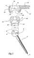
- the figure 1illustrates a first embodiment of the connecting device according to the invention, which comprises a pedicle screw 2, intended to be secured in a not shown vertebral body.
- This pedicle screwwhich thus constitutes a fixed element, is provided with a spherical head 4 having an equatorial flattening surface 6 extending in an inclined manner, in that it is not perpendicular to the main axis A of the 2.
- the head 4is further hollowed with a blind hole 8 for receiving an operating member, in particular the end of a screwdriver, not shown.
- the device represented in figure 1also comprises a movable element, partially illustrated, which is designated as a whole by the reference 10.
- This movable elementhas a body 12, which extends between the two vertebrae that connects the device of the invention and which is completed by two hollow ends, of which only one 14 is shown.
- Each enddefines a housing 16, forming an interior volume of the element 10, which is bordered by walls 18 forming a sphere section. These walls have a notch 20, to expand locally the passage section of the housing 16, so as to allow the introduction of an intermediate element, as will be described in what follows. Moreover, the transverse dimension 1 of the outlet 16 'of the housing 16 is smaller than the diameter L of this housing.
- the device of the figure 1finally comprises an intermediate element 22, whose outer surface 24 forms a sphere portion, whose diameter is identical to that L of the housing 16.
- the intermediate element 22is hollowed with a through opening, which defines a housing 26, forming an interior volume bordered by truncated spherical walls, whose diameter D is identical to that of the head 4.
- the housing 26communicates with a chamber 30 allowing the passage of the aforementioned maneuvering member, towards the blind hole 8.
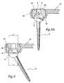
- this intermediate element 22is arranged, so that its spherical outer surface 24 located near the outlet 16 '. Then, the intermediate element 22 and the movable element 10 are moved axially towards each other. The intermediate element and the mobile element are not connected in rotation or in translation, in this insertion position.
- the intermediate element 22is then rotated about its axis, so that its outer surface 24 extends in the vicinity of the inner walls 18, as shown in FIG. 2C. Once these operations are performed, the intermediate element 22 has no degree of freedom in translation relative to the movable element, in this position of use. Indeed, the transverse dimension 1 of the outlet 16 'is smaller than the outside diameter of the intermediate element 22. On the other hand, the latter has three degrees of freedom in rotation with respect to the movable element 10.
- This intermediate element 22is then brought closer to the screw 2, according to a translation parallel to the main axis of this intermediate element 22. Since the transverse dimension d of the flat is equal to, or slightly less than, the transverse dimension of the outlet 27 of the housing 26, this allows a free introduction of the head 4 into the housing 26, illustrated in FIG. figure 3 .
- the periphery of the outlet 27is substantially rigid, that is to say non-deformable.
- the intermediate element 22may be made entirely of a rigid material, especially metal.
- this intermediate elementmay be made of a deformable material, such as polyethylene, a rigid ring then being attached to the vicinity of this outlet.
- the head 4is rotated inside the housing, so that the flat 6 is again inclined, that is to say, it is no longer facing the aforementioned outlet 27.
- the head 4is then free to pivot relative to this housing 26, but has no degree of freedom in translation relative to the intermediate element 22, since the diameter D of the head 4 is greater than the transverse dimension of outlet 27 of housing 26.
- each pedicle screwin a corresponding vertebral body. Then, each intermediate element 22 is introduced into the internal volume 16 of the mobile element 10, as explained with reference to FIG. figure 2 .
- the fixed element and the movable elementare then brought together mutually, and the intermediate element 22 is tilted within its housing 6.
- the intermediate element 22 thus tilted, relative to the pedicle screw 2is then brought closer to way that the flat 6 cooperates with the periphery of the outlet 27, as illustrated in FIG. figure 3 .
- an abutment meansadvantageously removable, such as a screw 32.
- the latterby limiting the pivoting of the head 4 relative to the intermediate element 22, prevents this head from recovering its position to the figure 3 , which avoids any separation between the intermediate element 22 and the pedicle screw 2.
- FIG 4illustrates an alternative embodiment of the invention, wherein the pedicle screw 2 'is provided with a spherical head 4' itself provided with an inclined equatorial flat 6 '.
- This head 4 'is introduced, in a manner analogous to that described above, into an intermediate element 22' provided with an internal volume 26 '.
- the spherical head 4 'and the interior volume 26'are concentric. Furthermore, the intermediate element 22 'is received in an interior volume 16' of a movable element 10 ', in a manner analogous to what has been described above.
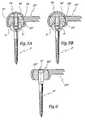
- FIGS. 5 and 5Aillustrate alternative embodiments in which there is provided removable fastening means for securing the pedicle screw 2 ", either with the movable element 10" or with the intermediate element 22 ".
- the head 4 of the pedicle screwis provided with a tapping 5 ", cooperating with a threaded rod 32 of a fixing element 34.
- the latteralso comprises a dome 36 in the form of a mushroom, bearing the walls of the end 14" of the movable element 10 ".
- the dome 36 'of the fixing element 34'is also supported on the end of the intermediate element 22 ", while the threaded rod 32 'is secured to the spherical head 4" of the pedicle screw.
- the figure 6illustrates a variant not covered by the invention, wherein the intermediate element 22 "'is dug a tapping 23"'.
- the lattercooperates with a threaded end 3 "'of the pedicle screw 2"', which is devoid of spherical head.
- the intermediate element 22 "'is also received, with a ball joint, in the movable element 10"', as in the previous examples.
- the pedicle screw described abovecan be replaced by a stem extending from a sacred plate, namely intended to be screwed on the sacrum.
- FIGS. Figures 1 to 3illustrate another embodiment of the invention, in which at least two pedicle screws 2 are used, as well as at least two intermediate elements 22, identical to those described with reference to FIGS. Figures 1 to 3 .
- the movable element 110comprises a tubular body 112, which is terminated by two closed ends 114 and is hollowed out with a first longitudinal notch 120, the periphery of which is substantially rigid, making it possible to introduce each intermediate element 22 into the interior volume. 116 of the movable member 110.
- This embodimentgives three degrees of freedom in rotation to the intermediate element 22 with respect to the movable element 110, and also allows axial sliding of this intermediate element along the cylindrical body 112.
- the head 4 of each screwmay be concentric with respect to the intermediate element, as in the embodiment described with reference to the figure 4 .
- the figure 9illustrates a device for connecting three neighboring vertebrae.
- This devicecomprises two end screws 2 ', similar to those of the figure 4 .
- Each screwcomprises a head 4 'provided with a flat part 6', cooperating with an intermediate element 22 '.
- the latteris received in the inner volume 16 'of a movable member 10', which is terminated, opposite its end receiving the intermediate member 22 ', by a spherical head 15'.
- an additional screw 3 'placed in the middle position. It comprises an elongate head 5 ', in which are formed two housings 7', whose truncated spherical walls extend in an angular sector greater than 180 °.
- each housing 7is open to the opposite of each other, substantially perpendicular to the main axis of this screw 3 '.
- the transverse dimension of the outlet of each housing 7 'is smaller than the diameter of its spherical walls.
- the spherical head 15 'of each movable element 10'which is provided with an inclined equatorial flat 17 ', cooperates with one of the housings 7' of the central screw 3 '.
- each spherical head 15 'into the interior volume of a corresponding housing 7'as has been described above for the introduction of the head 4 of the screw 2, in the interior volume of the intermediate element 22 '.
- each intermediate element 22 'is introduced into the interior volume of a mobile element 10'.
- the head 4 'of each end screw 2'is introduced into the internal volume of a corresponding intermediate element 22 '.
- the figure 10illustrates a device for connecting two neighboring vertebrae, as well as the sacrum.
- Two similar movable members 60are provided, each of which comprises a rod 61.
- the latteris terminated at both ends by a spherical head 65 provided with inclined inclined flats 67.
- each movable member 60is received in an intermediate member 72, similar to those 22, 22', 22 "and 22" 'described above.
- this intermediate element 72is received in the interior volume of a head 54, 55, respectively belonging to the pedicle screw 52 or to the sacred plate 53.
- the mutual connection between the head 65, the intermediate element 72, and the screw 52 or the plate 53is similar to that existing between, for example, the head 4 of the screw 2, the intermediate element 22 and the element mobile 10.
- the head 65is substituted for the head 4, the internal volume of the screw 52 or the plate 53 replaces the internal volume of the movable element 10, while the intermediate element 72 ensures the articulation of the element mobile 60 and the screw 52, just as the intermediate element 22 ensures the articulation of the screw 2 and the movable element 10.
- the figures 11 and 12illustrate a device for mutually connecting two lumbar vertebrae, as well as the sacrum.
- This devicecomprises an upper pedicle screw 152, terminated by a spherical head 154 provided with an inclined flat portion 156. Furthermore, there is provided a sacred plate 153, terminated by a spherical head 155 provided with an inclined flat portion 157. This device also comprises a median screw 159 terminated by a spherical head 161 provided with an inclined equatorial flat 163.
- an elongate plate 165each end of which is hollowed out of a corresponding cell 167 Each cell is similar to the housing 16 shown figure 1 .
- This elongate plate 165is also hollowed out with an oblong slot 169.
- the head 154, 155 of the end screw 152 or the plate 153is received in a corresponding cell 167, with the interposition of an intermediate element 172, similar in particular to that 22.
- the head 161 of the middle screw 159is received in the inner volume of an intermediate element 172 ', which differs from that 172, in that it is provided, opposite its outlet, a threaded rod 173', capable of cooperating with a nut 174 .
- each intermediate element 172The heads 154, 155 are then introduced into the interior volume of each intermediate element 172. To do this, it may be wise to rotate these intermediate elements, without for this to move in translation the elongated plate 165, with respect to the screw 152. and to the plate 153. This can be achieved by means of a palpator 175, the end of which passes through the opening of the cell 167 opposite the vertebrae.
- the intermediate element 172Before bringing the elongated plate 165 closer to the vertebrae, the intermediate element 172 'has been placed on the spherical head 161 of the central screw 159. The stem 173' of this intermediate element then passes through the light 169 of the plaque. It is thus possible, by screwing the nut 174 'on the threaded rod 173', to move, relative to the elongated plate 165, the middle screw 159 according to the arrow F. This is particularly advantageous, insofar as this allows to induce a displacement of the last lumbar vertebra according to this arrow F, that is to say to "pull" this vertebra.
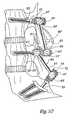
- FIG 13illustrates a further variant embodiment of the invention, wherein the all 165 plate is replaced by a connecting member 215, which comprises a rod 219, terminated by two disks 221, each of which is provided with a cell 217, similar to those 167.
- Each end disk 221is capable of cooperating, with the interposition of an intermediate element 172, with the screw 152 or the sacred plate 153. Moreover, the threaded rod 173 'of the intermediate element 172' is capable of traversing the orifice 227 of the intermediate disk 223, similarly to the oblong slot 169.
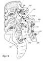
- the figure 14illustrates a further variant of the invention.
- the spherical head of each screw 152 or plate 153is received in the interior volume of a corresponding intermediate member 172 '.
- each threaded rod 173 'of a corresponding intermediate element 172'is able to penetrate the slot 269 of the plate 265, so as to cooperate with a corresponding nut 174 '.
- the figure 15illustrates a last embodiment of the invention.
- connecting member 315comprising a rod 319 on which discs 323 are arranged, which can be fixed by means of collars 325.
- each disk 323is able to receive the threaded rod 173 'of an intermediate element 172', which cooperates with the spherical head of a screw 152, or of a sacred plate 153.
- Each rod 173 'is also able to receive a nut 174 '.
- the inventionmakes it possible to achieve the objectives mentioned above.
- the various components of the intervertebral connection device of the inventionhave a relatively simple structure.
- the assembly of these elementsis particularly and can be performed by a surgeon, without the latter having to implement a significant physical force.
- the mounting of the various elements of the connecting device of the inventionalso induces no deformation thereof, which is advantageous in terms of mechanical reliability.
- the intervertebral connection device of the inventionhas a high resistance to with respect to mechanical stresses, in particular in tension. Indeed, the presence of the intermediate element makes it possible to transmit only to a very small extent the possible forces to which the connection device according to the invention is subjected.
Landscapes
- Health & Medical Sciences (AREA)
- Orthopedic Medicine & Surgery (AREA)
- Life Sciences & Earth Sciences (AREA)
- Neurology (AREA)
- Surgery (AREA)
- Heart & Thoracic Surgery (AREA)
- General Health & Medical Sciences (AREA)
- Biomedical Technology (AREA)
- Nuclear Medicine, Radiotherapy & Molecular Imaging (AREA)
- Medical Informatics (AREA)
- Molecular Biology (AREA)
- Animal Behavior & Ethology (AREA)
- Engineering & Computer Science (AREA)
- Public Health (AREA)
- Veterinary Medicine (AREA)
- Prostheses (AREA)
- Surgical Instruments (AREA)
- Massaging Devices (AREA)
- Orthopedics, Nursing, And Contraception (AREA)
Abstract
Description
Translated fromFrenchLa présente invention concerne un dispositif de liaison intervertébral.The present invention relates to an intervertebral connection device.
On connaît un tel dispositif qui comprend au moins deux vis pédiculaires, dont chacune possède une première extrémité solidarisée à un corps vertébral correspondant, une portion intermédiaire renflée, ainsi qu'une seconde extrémité filetée. Des organes auxiliaires, pourvus d'une arche de fixation d'une tige s'étendant entre les vertèbres, sont disposés sur chacune des portions renflées précitées. Un boulon, coopérant avec l'extrémité filetée de chaque vis, permet l'immobilisation de chaque organe auxiliaire, une fois ce dernier mis en place de façon appropriée.Such a device is known which comprises at least two pedicle screws, each of which has a first end secured to a corresponding vertebral body, an enlarged intermediate portion, and a second threaded end. Auxiliary members, provided with an arch for fixing a rod extending between the vertebrae, are arranged on each of the aforementioned bulged portions. A bolt, cooperating with the threaded end of each screw, allows the immobilization of each auxiliary member, once the latter set up appropriately.
Ce dispositif connu présente cependant certains inconvénients, en ce sens qu'il implique un procédé de montage relativement délicat. Par ailleurs, une fois implanté, il n'offre aucun degré de liberté entre les différents éléments qui le constituent. Ainsi, lorsque des efforts s'exercent au niveau des corps vertébraux, cette absence de degré de liberté induit une transmission de ces efforts sur l'ensemble du dispositif, de sorte que ce dernier a tendance à se désolidariser des vertèbres qu'il relie et induit par ailleurs des dysfonctionnements au niveau de l'ensemble de la chaîne vertébrale.
Afin de pallier ces différents inconvénients, la présente invention se propose de réaliser un dispositif dont la structure est simple, dont le montage est aisé et qui est implanté de façon fiable dans les vertèbres qu'il relie.In order to overcome these various drawbacks, the present invention proposes to provide a device whose structure is simple, whose assembly is easy and which is reliably implanted in the vertebrae that it connects.
A cet effet, elle a pour objet un dispositif de liaison intervertébral tel que défini dans la revendication 1.For this purpose, it relates to an intervertebral connection device as defined in claim 1.
L'invention va être décrite ci-dessous, en référence aux dessins annexés, donnés uniquement à titre d'exemples non limitatifs et dans lesquels :
- la
figure 1 est une vue en coupe longitudinale, illustrant les différents éléments constitutifs d'un dispositif de liaison intervertébral conforme à un premier mode de réalisation de l'invention; - les
figures 2, 2A et 2B sont des vues analogues à lafigure 1 , illustrant trois étapes du montage d'un élément intermédiaire du dispositif de lafigure 1 , dans le volume intérieur d'un élément mobile de ce dispositif ; - les
figures 3 et 3A sont des vues analoguesfigure 1 , illustrant l'introduction d'un élément fixe du dispositif de lafigure 1 , dans le volume intérieur de son élément intermédiaire ; - les
figures 4 à 5 sont des vues analogues à lafigure 3A , illustrant des variantes de réalisation du dispositif conforme à l'invention ; - la
figure 6 montre une variante non couverte par l'invention - les
figures 7 et 8 sont des vues en coupe respectivement longitudinale et transversale, d'un dispositif conforme à un mode supplémentaire de réalisation de l'invention, - les
figures 9 et10 sont des vues en coupe longitudinale, illustrant deux variantes supplémentaires de réalisation de l'invention ; - la
figure 11 est une vue en perspective, illustrant les différents éléments d'un dispositif conforme à une variante supplémentaire de l'invention ; - la
figure 12 est une vue en coupe longitudinale du dispositif de lafigure 11 , une fois monté ; et - les
figures 13 à 15 sont des vues en perspective, analogues à lafigure 11 , illustrant trois variantes supplémentaires de réalisation de l'invention.
- the
figure 1 is a longitudinal sectional view, illustrating the various components of an intervertebral connection device according to a first embodiment of the invention; - the
Figures 2, 2A and 2B are similar views to thefigure 1 , illustrating three stages of mounting an intermediate element of the device of thefigure 1 in the interior volume of a movable member of this device; - the
Figures 3 and 3A are similar viewsfigure 1 , illustrating the introduction of a fixed element of the device of thefigure 1 in the interior volume of its intermediate element; - the
Figures 4 to 5 are similar views to thefigure 3A , illustrating alternative embodiments of the device according to the invention; - the
figure 6 shows a variant not covered by the invention - the
Figures 7 and 8 are respectively longitudinal and transverse sectional views of a device according to an additional embodiment of the invention, - the
figures 9 and10 are longitudinal sectional views illustrating two additional variants of embodiment of the invention; - the
figure 11 is a perspective view, illustrating the various elements of a device according to a further variant of the invention; - the
figure 12 is a longitudinal sectional view of the device of thefigure 11 once mounted; and - the
Figures 13 to 15 are perspective views, similar to thefigure 11 illustrating three further embodiments of the invention.
La
Le dispositif représenté à la
Chaque extrémité définit un logement 16, formant un volume intérieur de l'élément 10, qui est bordé par des parois 18 formant un tronçon de sphère. Ces parois possèdent une échancrure 20, permettant d'élargir localement la section de passage du logement 16, de manière à permettre l'introduction d'un élément intermédiaire, comme cela sera décrit dans ce qui suit. Par ailleurs, la dimension transversale1 du débouché 16' du logement 16 est inférieure au diamètre L de ce logement.Each end defines a
Le dispositif de la
Le montage du dispositif illustré à la
Il s'agit, dans un premier temps, d'introduire l'élément intermédiaire 22 dans le volume intérieur 16 de l'élément mobile 10. A cet effet, on dispose cet élément intermédiaire 22, de sorte que sa surface extérieure sphérique 24 se trouve au voisinage du débouché 16'. Puis, on rapproche axialement l'un de l'autre l'élément intermédiaire 22 et l'élément mobile 10. L'élément intermédiaire et l'élément mobile ne sont pas liés en rotation ni en translation, dans cette position d'introduction.It is a question of introducing the
On fait ensuite pivoter l'élément intermédiaire 22 autour de son axe, de manière que sa surface extérieure 24 s'étende au voisinage des parois intérieures 18, comme le montre la figure 2C. Une fois ces opérations réalisées, l'élément intermédiaire 22 ne possède aucun degré de liberté en translation par rapport à l'élément mobile, dans cette position d'utilisation. En effet, la dimension transversale1 du débouché 16' est inférieure au diamètre extérieur de l'élément intermédiaire 22. En revanche, ce dernier possèd trois degrés de liberté en rotation par rapport à l'élémen mobile 10.The
Puis, comme le montre la
On rapproche alors cet élément intermédiaire 22 de la vis 2, selon une translation parallèle à l'axe principal de cet élément intermédiaire 22. Etant donné que la dimension transversaled du méplat est égale, ou légèrement inférieure, à la dimension transversaled' du débouché 27 du logement 26, ceci permet une libre introduction de la tête 4 dans ce logement 26, illustrée à la
Le pourtour du débouché 27 est sensiblement rigide, c'est-à-dire non déformable. A cet effet, l'élément intermédiaire 22 peut être réalisé entièrement en un matériau rigide, notamment métallique. En variante, cet élément intermédiaire peut être réalisé en un matériau déformable, tel que du polyéthylène, une bague rigide étant alors rapportée au voisinage de ce débouché.The periphery of the
Ensuite, on fait pivoter la tête 4 à l'intérieur du logement, de manière que le méplat 6 soit à nouveau incliné, c'est-à-dire qu'il ne se trouve plus en regard du débouché 27 précité. La tête 4 est alors libre de pivoter par rapport à ce logement 26, mais ne possède aucun degré de liberté en translation par rapport à l'élément intermédiaire 22, étant donné que le diamètre D de la tête 4 est supérieur à la dimension transversale du débouché 27 du logement 26.Then, the
Une fois le dispositif mis dans la configuration illustrée à la
A titre de variante de montage, il est possible de tout d'abord chaque vis pédiculaire dans un corps vertébral correspondant. Puis, on introduit chaque élément intermédiaire 22 dans le volume intérieur 16 de l'élément mobile 10, comme cela est expliqué en référence à la
On rapproche alors mutuellement l'élément fixe et l'élément mobile, et on fait basculer l'élément intermédiaire 22 au sein de son logement 6. On rapproche ensuite l'élément intermédiaire 22 ainsi basculé, par rapport à la vis pédiculaire 2, de manière que le méplat 6 coopère avec le pourtour du débouché 27, comme cela est illustré à la
Une fois le dispositif de l'invention placé dans la configuration de cette
La
Il est à noter que, contrairement à l'exemple décrit en référence aux
Les
Dans le mode de réalisation de la
La
A titre de variante on peut remplacer la vis pédiculaire décrite ci-dessus par une tige s'étendant depuis une plaque sacrée, à savoir destinée à être vissée sur le sacrum.Alternatively the pedicle screw described above can be replaced by a stem extending from a sacred plate, namely intended to be screwed on the sacrum.
Les
L'élément mobile 110 comprend un corps tubulaire 112, qui est terminé par deux extrémités fermées 114 et se trouve creusé d'une première échancrure longitudinale 120, dont le pourtour est sensiblement rigide, permettant d'introduire chaque élément intermédiaire 22 dans le volume intérieur 116 de l'élément mobile 110.The
Cette introduction est réalisée de façon analogue à celle décrite en référence aux
Ce mode de réalisation confère trois degrés de liberté en rotation à l'élément intermédiaire 22 par rapport à l'élément mobile 110, et permet également un coulissement axial de cet élément intermédiaire, le long du corps cylindri-que 112. En variante, la tête 4 de chaque vis peut être concentrique par rapport à l'élément intermédiaire, comme dans l'exemple de réalisation décrit à la référence à la
La
Ce dispositif comprend deux vis d'extrémité 2', analogues à celles de la
Par ailleurs, il est prévu une vis supplémentaire 3', placée en position médiane. Elle comprend une tête 5' allongée, dans laquelle sont ménagés deux logements 7', dont les parois sphériques tronquées s'étendent selon un secteur angulaire supérieur à 180°.Furthermore, there is provided an additional screw 3 ', placed in the middle position. It comprises an elongate head 5 ', in which are formed two housings 7', whose truncated spherical walls extend in an angular sector greater than 180 °.
Ces deux logements sont ouverts à l'opposé l'un de l'autre, de façon sensiblement perpendiculaire à l'axe principal de cette vis 3'. La dimension transversale du débouché de chaque logement 7' est inférieure au diamètre de ses parois sphériques. La tête sphérique 15' de chaque élément mobile 10', qui est pourvue d'un méplat équatorial incliné 17', coopère avec l'un des logements 7' de la vis médiane 3'.These two housings are open to the opposite of each other, substantially perpendicular to the main axis of this screw 3 '. The transverse dimension of the outlet of each housing 7 'is smaller than the diameter of its spherical walls. The spherical head 15 'of each movable element 10', which is provided with an inclined equatorial flat 17 ', cooperates with one of the housings 7' of the central screw 3 '.
En vue du montage de la prothèse, il s'agit tout d'abord d'introduire chaque tête sphérique 15' dans le volume intérieur d'un logement 7' correspondant, comme cela a été décrit précédemment pour l'introduction de la tête 4 de la vis 2, dans le volume intérieur de l'élément intermédiaire 22'.With a view to mounting the prosthesis, it is first necessary to introduce each spherical head 15 'into the interior volume of a corresponding housing 7', as has been described above for the introduction of the
Puis, on introduit chaque élément intermédiaire 22' dans le volume intérieur d'un élément mobile 10'. Enfin, on introduit la tête 4' de chaque vis d'extrémité 2', dans le volume intérieur d'un élément intermédiaire 22' correspondant.Then, each intermediate element 22 'is introduced into the interior volume of a mobile element 10'. Finally, the head 4 'of each end screw 2' is introduced into the internal volume of a corresponding intermediate element 22 '.
La
Il est prévu deux éléments mobiles 60 analogues, dont chacun comprend une tige 61. Cette dernière est terminée, à ses deux extrémités, par une tête sphérique 65 munie de méplats inclinés inclinés 67.Two similar
Il est par ailleurs prévu une vis médiane 53' analogue à celle 3' de la
Par ailleurs, il est prévu deux éléments fixes d'extrémité, à savoir une vis pédiculaire 52, ainsi qu'une plaque 53, fixée sur le sacrum. A son extrémité opposée à la vis médiane 53', chaque élément mobile 60 est reçu dans un élément intermédiaire 72, analogue à ceux 22, 22', 22" et 22"' décrit ci-dessus.Furthermore, there are two fixed end elements, namely a
Par ailleurs, cet élément intermédiaire 72 est reçu dans le volume intérieur d'une tête 54, 55, appartenant respectivement à la vis pédiculaire 52 ou à la plaque sacrée 53.Moreover, this
La liaison mutuelle entre la tête 65, l'élément intermédiaire 72, et la vis 52 ou la plaque 53, est analogue à celle existant entre, par exemple, la tête 4 de la vis 2, l'élément intermédiaire 22 et l'élément mobile 10.The mutual connection between the
En d'autres termes, dans cette
Les
Ce dispositif comporte une vis pédiculaire supérieure 152, terminée par une tête sphérique 154 pourvue d'un méplat incliné 156. Par ailleurs, il est prévu une plaque sacrée 153, terminée par une tête sphérique 155 pourvue d'un méplat incliné 157. Ce dispositif comporte également une vis médiane 159 terminée par une tête sphérique 161 pourvue d'un méplat équatorial incliné 163.This device comprises an
Il est en outre prévu une plaque allongée 165, dont chaque extrémité est creusée d'une alvéole correspondante 167 Chaque alvéole est analogue au logement 16 représenté
La tête 154, 155 de la vis d'extrémité 152 ou de la plaque 153 est reçue dans une alvéole 167 correspondante, avec interposition d'un élément intermédiaire 172, analogue notamment à celui 22. La tête 161 de la vis médiane 159 est reçue dans le volume intérieur d'un élément intermédiaire 172', qui diffère de celui 172, en ce sens qu'il est pourvu, à l'opposé de son débouché, d'une tige filetée 173', susceptible de coopérer avec un écrou 174'.The
Le montage du dispositif des
Il s'agit tout d'abord d'introduire chaque élément intermédiaire 172 dans une alvéole 167 correspondante, comme cela a été décrit en référence aux
On introduit alors les têtes 154, 155 dans le volume intérieur de chaque élément intermédiaire 172. Pour ce faire, il peut être judicieux de faire pivoter ces éléments intermédiaires, sans pour cela déplacer en translation la plaque allongée 165, par rapport à la vis 152 et à la plaque 153. Ceci peut être réalisé par l'intermédiaire d'un palpateur 175, dont l'extrémité traverse l'ouverture de l'alvéole 167 opposée aux vertèbres.The
Il est à noter que, avant de rapprocher la plaque allongée 165 des vertèbres, l'élément intermédiaire 172' a été placé sur la tête sphérique 161 de la vis médiane 159. La tige 173' de cet élément intermédiaire traverse alors la lumière 169 de la plaque. Il est ainsi possible, par vissage de l'écrou 174' sur la tige filetée 173', de déplacer, par rapport à la plaque allongée 165, la vis médiane 159 selon la flèche F. Ceci est particulièrement avantageux, dans la mesure où cela permet d'induire un déplacement de la dernière vertèbre lombaire selon cette flèche F, c'est-à-dire de "tirer" cette vertèbre.It should be noted that, before bringing the
La
Il est par ailleurs prévu un disque intermédiaire 223, susceptible d'être fixé sur la tige 219 par un collier 225. Ce disque 223 est creusé d'un orifice médian 227.There is also provided an
Chaque disque d'extrémité 221 est susceptible de coopérer, avec interposition d'un élément intermédiaire 172, avec la vis 152 ou la plaque sacrée 153. Par ailleurs, la tige filetée 173' de l'élément intermédiaire 172' est susceptible de traverser l'orifice 227 du disque intermédiaire 223, de façon analogue à la lumière oblongue 169.Each
La
En outre, chaque tige filetée 173' d'un élément intermédiaire correspondant 172' est apte à pénétrer dans la lumière 269 de la plaque 265, de façon à coopérer avec un écrou correspondant 174'.In addition, each threaded rod 173 'of a corresponding intermediate element 172' is able to penetrate the
La
Il est prévu un organe de liaison 315, comprenant une tige 319 sur laquelle sont disposés des disques 323, susceptibles d'être fixés au moyen de colliers 325.There is provided a connecting
L'orifice 327 de chaque disque 323 est apte à recevoir la tige filetée 173' d'un élément intermédiaire 172', qui coopérère avec la tête sphérique d'une vis 152, ou bien d'une plaque sacrée 153. Chaque tige 173' est par ailleurs apte à recevoir un écrou 174'.The
L'invention permet de réaliser les objectifs précédemment mentionnés.The invention makes it possible to achieve the objectives mentioned above.
En effet, les différents éléments constitutifs du dispositif de liaison intervertébral de l'invention possèdent une structure relativement simple.Indeed, the various components of the intervertebral connection device of the invention have a relatively simple structure.
L'assemblage de ces éléments est particulièrement et peut être réalisé par un chirurgien, sans que ce dernier n'ait à mettre en oeuvre une force physique importante.The assembly of these elements is particularly and can be performed by a surgeon, without the latter having to implement a significant physical force.
Le montage des différents éléments du dispositif de liaison de l'invention n'induit par ailleurs aucune déformation de ceux-ci, ce qui est avantageux en termes de fiabilité mécanique.The mounting of the various elements of the connecting device of the invention also induces no deformation thereof, which is advantageous in terms of mechanical reliability.
Il est à noter que la présence de l'élément intermédiaire autorise le montage mutuel de l'élément fixe et de l'élément mobile, quand bien même il n'existe pratiquement aucun débattement en rotation entre ces deux éléments.It should be noted that the presence of the intermediate element allows mutual mounting of the fixed element and the movable element, even though there is virtually no rotational movement between these two elements.
Enfin, une fois le dispositif de liaison intervertébral de l'invention assemblé, il possède une résistance élevée à l'égard des contraintes mécaniques, s'exerçant notamment en traction. En effet, la présence de l'élément intermédiaire permet de ne transmettre que dans une très faible mesure les éventuels efforts auxquels est soumis le dispositif de liaison conforme à l'invention.Finally, once the intervertebral connection device of the invention is assembled, it has a high resistance to with respect to mechanical stresses, in particular in tension. Indeed, the presence of the intermediate element makes it possible to transmit only to a very small extent the possible forces to which the connection device according to the invention is subjected.
Claims (14)
- An intervertebral linking device designed to connect at least two vertebrae together, the device beingcharacterised in that it comprises:- at least one fixed member (2; 2'; 2"; 52, 53; 152, 153) fixedly attached to a vertebra or the sacrum,- at least one movable linking member (10; 10'; 10"; 60; 110; 165; 215; 265; 315) which can move in relation to the one or more fixed members,- together with at least one intermediate member (22; 22'; 22"; 72; 172, 172') which provides an articulation between the or all the movable members in relation to the or all fixed members,-in that the or all intermediate members are received within an internal space (16; 16'; 116; 167, 169; 217, 227; 327) in the said moving member (10; 10'; 10"; 110; 165; 215; 265; 315) or the said fixed member (52, 53),-in that the fixed member (2' 2'; 2"; 152, 153) or the moving member (60) are at least partly received within an internal space (26; 26') in the intermediate member,- andin that means are provided to enable the said fixed member (2; 2'; 2"; 152, 153) or the said moving member (60) to be fixedly attached in relation to the said intermediate member, these means preventing lateral movement comprising the perimeter of the non-deformable opening (27) of the interior space (26) in the intermediate member (22),-in that the or all the intermediate members (2; 22'; 172, 172') are received within an internal space in the moving member (10; 10'; 10"; 110; 165; 215; 265; 315),in that the fixed member (2; 2'; 2"; 152, 153) is at least partly received within an internal space of the intermediate member, andin that means are provided to prevent at least lateral movement of the fixed member in relation to the intermediate member,
in that the said fixed member (2; 2'; 2") has at least one degree of freedom in rotation in relation to the intermediate member (22; 22'; 22"),
in that the said fixed member (2; 2'; 2") has a spherical external surface capable of acting in concert with a corresponding spherical internal surface (28) of the intermediate member (22; 22'; 22"), and
in that the spherical external surface of the said fixed member is provided with an equatorial flat (6; 6') for insertion of the said fixed member (2; 2'; 2") within the internal space in the intermediate member (22; 22'; 22"). - A device according to Claim 1,characterised in that the said intermediate member (22; 22'; 22"; 172) is fixedly attached with regard to lateral movement in relation to the said moving member (10; 10'; 10"; 110; 165; 215).
- A device according to Claim 2,characterised in that the opening (16') of the internal space (16) of the moving member (10) has a non-deformable perimeter which will prevent lateral movement of the intermediate member in relation to the moving member.
- A device according to Claim 2 or Claim 3,characterised in that the said intermediate member (22; 22'; 22") has a truncated spherical external surface (24) and acts in concert with a corresponding spherical internal surface (18) with which the said moving member (10; 10'; 10") is provided.
- A device according to Claim 4,characterised in that the fixed member (2') has a head (4') which is received within the internal space in the intermediate member (22') andin that the said head, the intermediate member and the internal space in the moving member (10') are concentric.
- A device according to Claim 2,characterised in that the said intermediate member (172') is also fixedly attached with regard to rotation in relation to the moving member (165; 215; 265; 315).
- A device according to Claim 1,characterised in that the intermediate member (22) has at least one degree of freedom, at least laterally, in relation to the said first moving member (110).
- A device according to Claim 7,characterised in that the said moving member (110) has a tubular portion (112) along which the said intermediate member (22) can slide.
- A device according to any one of Claims 2 to 8,characterised in that the said moving member (10; 10'; 10"; 110) has an embayment (20; 120) for insertion of the intermediate member (22; 22'; 22") within the internal space (16; 116) in this moving member.
- A device according to Claim 9,characterised in that the said fixed member (2) is provided with a stop member (32), in particular a movable one, which can limit pivoting of the intermediate member (22) in relation to the fixed member (2).
- A device according to any one of Claims 1 to 9,characterised in that when in use the fixed member (2"') is fixedly attached to the intermediate member (22"') with regard to both lateral movement and rotation.
- A device according to Claim 1,characterised in that each intermediate member (72) is received within an internal space in the fixed member (52, 53),in that the moving member (60) is at least partly received into an internal space in the intermediate member, andin that means are provided to enable the moving member to be fixedly attached to the intermediate member at least with regard to lateral movement.
- A device according to any one of the preceding claims,characterised in that the fixed member is a pedicle screw (2; 2'; 2"; 52, 152).
- A device according to any one of the preceding claims,characterised in that the fixed member is a plate (53, 153) which is designed to be attached to the sacrum.
Applications Claiming Priority (5)
| Application Number | Priority Date | Filing Date | Title |
|---|---|---|---|
| FR0008522 | 2000-06-30 | ||
| FR0008522AFR2810873B1 (en) | 2000-06-30 | 2000-06-30 | INTERVERTEBRAL LINK DEVICE |
| FR0010155AFR2812535B3 (en) | 2000-08-01 | 2000-08-01 | DEVICE INTENDED TO BE IMPLANTED IN AT LEAST ONE VERTEBRUS, AND USE OF THIS DEVICE |
| FR0010155 | 2000-08-01 | ||
| PCT/FR2001/002098WO2002000124A1 (en) | 2000-06-30 | 2001-06-29 | Intervertebral linking device |
Publications (2)
| Publication Number | Publication Date |
|---|---|
| EP1294297A1 EP1294297A1 (en) | 2003-03-26 |
| EP1294297B1true EP1294297B1 (en) | 2010-08-11 |
Family
ID=26212506
Family Applications (1)
| Application Number | Title | Priority Date | Filing Date |
|---|---|---|---|
| EP01949595AExpired - LifetimeEP1294297B1 (en) | 2000-06-30 | 2001-06-29 | Intervertebral linking device |
Country Status (8)
| Country | Link |
|---|---|
| US (2) | US7691131B2 (en) |
| EP (1) | EP1294297B1 (en) |
| JP (1) | JP2004500953A (en) |
| AT (1) | ATE476929T1 (en) |
| AU (2) | AU2001270720B2 (en) |
| CA (1) | CA2413474A1 (en) |
| DE (1) | DE60142780D1 (en) |
| WO (1) | WO2002000124A1 (en) |
Cited By (7)
| Publication number | Priority date | Publication date | Assignee | Title |
|---|---|---|---|---|
| US9510862B2 (en) | 2009-06-17 | 2016-12-06 | DePuy Synthes Products, Inc. | Revision connector for spinal constructs |
| US9848918B2 (en) | 2005-11-21 | 2017-12-26 | DePuy Synthes Products, Inc. | Polyaxial bone anchors with increased angulation |
| US10105163B2 (en) | 2009-04-15 | 2018-10-23 | DePuy Synthes Products, Inc. | Revision connector for spinal constructs |
| US10136923B2 (en) | 2007-07-20 | 2018-11-27 | DePuy Synthes Products, Inc. | Polyaxial bone fixation element |
| US10154859B2 (en) | 2008-09-29 | 2018-12-18 | DePuy Synthes Products, Inc. | Polyaxial bottom-loading screw and rod assembly |
| US10405892B2 (en) | 2008-11-03 | 2019-09-10 | DePuy Synthes Products, Inc. | Uni-planer bone fixation assembly |
| US11129648B2 (en) | 2008-09-12 | 2021-09-28 | DePuy Synthes Products, Inc. | Spinal stabilizing and guiding fixation system |
Families Citing this family (162)
| Publication number | Priority date | Publication date | Assignee | Title |
|---|---|---|---|---|
| US8187303B2 (en) | 2004-04-22 | 2012-05-29 | Gmedelaware 2 Llc | Anti-rotation fixation element for spinal prostheses |
| ES2270888T3 (en) | 1999-12-01 | 2007-04-16 | Henry Graf | INTERVERTEBRAL STABILIZATION DEVICE. |
| US7833250B2 (en) | 2004-11-10 | 2010-11-16 | Jackson Roger P | Polyaxial bone screw with helically wound capture connection |
| US6579319B2 (en) | 2000-11-29 | 2003-06-17 | Medicinelodge, Inc. | Facet joint replacement |
| US20050080486A1 (en) | 2000-11-29 | 2005-04-14 | Fallin T. Wade | Facet joint replacement |
| FR2817461B1 (en)* | 2000-12-01 | 2003-08-15 | Henry Graf | INTERVERTEBRAL STABILIZATION DEVICE |
| US6419703B1 (en) | 2001-03-01 | 2002-07-16 | T. Wade Fallin | Prosthesis for the replacement of a posterior element of a vertebra |
| US6565605B2 (en) | 2000-12-13 | 2003-05-20 | Medicinelodge, Inc. | Multiple facet joint replacement |
| US6969610B2 (en)* | 2001-01-12 | 2005-11-29 | University Of Rochester | Methods of modifying cell structure and remodeling tissue |
| US7090698B2 (en) | 2001-03-02 | 2006-08-15 | Facet Solutions | Method and apparatus for spine joint replacement |
| US6802844B2 (en)* | 2001-03-26 | 2004-10-12 | Nuvasive, Inc | Spinal alignment apparatus and methods |
| US7862587B2 (en) | 2004-02-27 | 2011-01-04 | Jackson Roger P | Dynamic stabilization assemblies, tool set and method |
| FR2827499B1 (en) | 2001-07-20 | 2004-05-07 | Henry Graf | INTERVERTEBRAL LINK DEVICE |
| CA2471843C (en)* | 2001-12-24 | 2011-04-12 | Synthes (U.S.A.) | Device for osteosynthesis |
| US20050288668A1 (en)* | 2002-06-24 | 2005-12-29 | Bernhard Brinkhaus | Spinal column support system |
| US8876868B2 (en) | 2002-09-06 | 2014-11-04 | Roger P. Jackson | Helical guide and advancement flange with radially loaded lip |
| US20060217815A1 (en)* | 2002-09-24 | 2006-09-28 | Biomet Manufacturing Corp | Modular prosthetic head having a flat portion to be implanted into a constrained liner |
| US7588589B2 (en)* | 2003-03-20 | 2009-09-15 | Medical Designs Llc | Posterior spinal reconstruction system |
| US7621918B2 (en) | 2004-11-23 | 2009-11-24 | Jackson Roger P | Spinal fixation tool set and method |
| CA2524145A1 (en) | 2003-05-02 | 2004-11-18 | Yale University | Dynamic spine stabilizer |
| US8652175B2 (en)* | 2003-05-02 | 2014-02-18 | Rachiotek, Llc | Surgical implant devices and systems including a sheath member |
| US7635379B2 (en) | 2003-05-02 | 2009-12-22 | Applied Spine Technologies, Inc. | Pedicle screw assembly with bearing surfaces |
| US20050171543A1 (en)* | 2003-05-02 | 2005-08-04 | Timm Jens P. | Spine stabilization systems and associated devices, assemblies and methods |
| US7377923B2 (en) | 2003-05-22 | 2008-05-27 | Alphatec Spine, Inc. | Variable angle spinal screw assembly |
| DE10326643A1 (en)* | 2003-06-11 | 2004-12-30 | Mückter, Helmut, Dr. med. Dipl.-Ing. | Osteosynthesis plate or comparable implant with ball sleeve |
| US7776067B2 (en) | 2005-05-27 | 2010-08-17 | Jackson Roger P | Polyaxial bone screw with shank articulation pressure insert and method |
| US7766915B2 (en) | 2004-02-27 | 2010-08-03 | Jackson Roger P | Dynamic fixation assemblies with inner core and outer coil-like member |
| US8926670B2 (en) | 2003-06-18 | 2015-01-06 | Roger P. Jackson | Polyaxial bone screw assembly |
| US7967850B2 (en) | 2003-06-18 | 2011-06-28 | Jackson Roger P | Polyaxial bone anchor with helical capture connection, insert and dual locking assembly |
| US8366753B2 (en) | 2003-06-18 | 2013-02-05 | Jackson Roger P | Polyaxial bone screw assembly with fixed retaining structure |
| ATE407634T1 (en)* | 2003-09-08 | 2008-09-15 | Synthes Gmbh | LONGITUDINAL BEAM |
| US7588590B2 (en) | 2003-12-10 | 2009-09-15 | Facet Solutions, Inc | Spinal facet implant with spherical implant apposition surface and bone bed and methods of use |
| US20050131406A1 (en)* | 2003-12-15 | 2005-06-16 | Archus Orthopedics, Inc. | Polyaxial adjustment of facet joint prostheses |
| US7179261B2 (en) | 2003-12-16 | 2007-02-20 | Depuy Spine, Inc. | Percutaneous access devices and bone anchor assemblies |
| US11419642B2 (en) | 2003-12-16 | 2022-08-23 | Medos International Sarl | Percutaneous access devices and bone anchor assemblies |
| US7527638B2 (en) | 2003-12-16 | 2009-05-05 | Depuy Spine, Inc. | Methods and devices for minimally invasive spinal fixation element placement |
| US8333789B2 (en) | 2007-01-10 | 2012-12-18 | Gmedelaware 2 Llc | Facet joint replacement |
| US7993373B2 (en) | 2005-02-22 | 2011-08-09 | Hoy Robert W | Polyaxial orthopedic fastening apparatus |
| US8562649B2 (en) | 2004-02-17 | 2013-10-22 | Gmedelaware 2 Llc | System and method for multiple level facet joint arthroplasty and fusion |
| US11241261B2 (en) | 2005-09-30 | 2022-02-08 | Roger P Jackson | Apparatus and method for soft spinal stabilization using a tensionable cord and releasable end structure |
| JP2007525274A (en) | 2004-02-27 | 2007-09-06 | ロジャー・ピー・ジャクソン | Orthopedic implant rod reduction instrument set and method |
| US8152810B2 (en) | 2004-11-23 | 2012-04-10 | Jackson Roger P | Spinal fixation tool set and method |
| US7160300B2 (en) | 2004-02-27 | 2007-01-09 | Jackson Roger P | Orthopedic implant rod reduction tool set and method |
| US7645294B2 (en) | 2004-03-31 | 2010-01-12 | Depuy Spine, Inc. | Head-to-head connector spinal fixation system |
| US7717939B2 (en) | 2004-03-31 | 2010-05-18 | Depuy Spine, Inc. | Rod attachment for head to head cross connector |
| US7914556B2 (en) | 2005-03-02 | 2011-03-29 | Gmedelaware 2 Llc | Arthroplasty revision system and method |
| WO2005117725A2 (en)* | 2004-05-27 | 2005-12-15 | Depuy Spine, Inc. | Tri-joint implant |
| US7507242B2 (en) | 2004-06-02 | 2009-03-24 | Facet Solutions | Surgical measurement and resection framework |
| US8764801B2 (en) | 2005-03-28 | 2014-07-01 | Gmedelaware 2 Llc | Facet joint implant crosslinking apparatus and method |
| US7931675B2 (en) | 2004-06-23 | 2011-04-26 | Yale University | Dynamic stabilization device including overhanging stabilizing member |
| US7351261B2 (en)* | 2004-06-30 | 2008-04-01 | Depuy Spine, Inc. | Multi-joint implant |
| US8021428B2 (en)* | 2004-06-30 | 2011-09-20 | Depuy Spine, Inc. | Ceramic disc prosthesis |
| US7261738B2 (en) | 2004-06-30 | 2007-08-28 | Depuy Spine, Inc. | C-shaped disc prosthesis |
| US7854752B2 (en) | 2004-08-09 | 2010-12-21 | Theken Spine, Llc | System and method for dynamic skeletal stabilization |
| AU2005277363A1 (en) | 2004-08-18 | 2006-03-02 | Fsi Acquisition Sub, Llc | Adjacent level facet arthroplasty devices, spine stabilization systems, and methods |
| US7717938B2 (en) | 2004-08-27 | 2010-05-18 | Depuy Spine, Inc. | Dual rod cross connectors and inserter tools |
| US7651502B2 (en)* | 2004-09-24 | 2010-01-26 | Jackson Roger P | Spinal fixation tool set and method for rod reduction and fastener insertion |
| US20060084976A1 (en)* | 2004-09-30 | 2006-04-20 | Depuy Spine, Inc. | Posterior stabilization systems and methods |
| US7896906B2 (en)* | 2004-12-30 | 2011-03-01 | Depuy Spine, Inc. | Artificial facet joint |
| US8092496B2 (en)* | 2004-09-30 | 2012-01-10 | Depuy Spine, Inc. | Methods and devices for posterior stabilization |
| US7766940B2 (en)* | 2004-12-30 | 2010-08-03 | Depuy Spine, Inc. | Posterior stabilization system |
| US7794477B2 (en)* | 2004-10-05 | 2010-09-14 | Warsaw Orthopedic, Inc. | Spinal implants and methods with extended multi-axial anchor assemblies |
| US7722654B2 (en)* | 2004-10-05 | 2010-05-25 | Warsaw Orthopedic, Inc. | Spinal implants with multi-axial anchor assembly and methods |
| US8267969B2 (en) | 2004-10-20 | 2012-09-18 | Exactech, Inc. | Screw systems and methods for use in stabilization of bone structures |
| US8025680B2 (en) | 2004-10-20 | 2011-09-27 | Exactech, Inc. | Systems and methods for posterior dynamic stabilization of the spine |
| US7935134B2 (en) | 2004-10-20 | 2011-05-03 | Exactech, Inc. | Systems and methods for stabilization of bone structures |
| US8226690B2 (en) | 2005-07-22 | 2012-07-24 | The Board Of Trustees Of The Leland Stanford Junior University | Systems and methods for stabilization of bone structures |
| US8162985B2 (en) | 2004-10-20 | 2012-04-24 | The Board Of Trustees Of The Leland Stanford Junior University | Systems and methods for posterior dynamic stabilization of the spine |
| US8241330B2 (en) | 2007-01-11 | 2012-08-14 | Lanx, Inc. | Spinous process implants and associated methods |
| US9055981B2 (en) | 2004-10-25 | 2015-06-16 | Lanx, Inc. | Spinal implants and methods |
| US8926672B2 (en) | 2004-11-10 | 2015-01-06 | Roger P. Jackson | Splay control closure for open bone anchor |
| WO2006057837A1 (en) | 2004-11-23 | 2006-06-01 | Jackson Roger P | Spinal fixation tool attachment structure |
| US8444681B2 (en) | 2009-06-15 | 2013-05-21 | Roger P. Jackson | Polyaxial bone anchor with pop-on shank, friction fit retainer and winged insert |
| US9168069B2 (en) | 2009-06-15 | 2015-10-27 | Roger P. Jackson | Polyaxial bone anchor with pop-on shank and winged insert with lower skirt for engaging a friction fit retainer |
| US8308782B2 (en) | 2004-11-23 | 2012-11-13 | Jackson Roger P | Bone anchors with longitudinal connecting member engaging inserts and closures for fixation and optional angulation |
| US9980753B2 (en) | 2009-06-15 | 2018-05-29 | Roger P Jackson | pivotal anchor with snap-in-place insert having rotation blocking extensions |
| US7901437B2 (en) | 2007-01-26 | 2011-03-08 | Jackson Roger P | Dynamic stabilization member with molded connection |
| US7722647B1 (en) | 2005-03-14 | 2010-05-25 | Facet Solutions, Inc. | Apparatus and method for posterior vertebral stabilization |
| US7931681B2 (en)* | 2005-04-14 | 2011-04-26 | Warsaw Orthopedic, Inc. | Anti-backout mechanism for an implant fastener |
| US7951169B2 (en)* | 2005-06-10 | 2011-05-31 | Depuy Spine, Inc. | Posterior dynamic stabilization cross connectors |
| US8523865B2 (en) | 2005-07-22 | 2013-09-03 | Exactech, Inc. | Tissue splitter |
| US7699875B2 (en) | 2006-04-17 | 2010-04-20 | Applied Spine Technologies, Inc. | Spinal stabilization device with weld cap |
| US7713288B2 (en) | 2005-08-03 | 2010-05-11 | Applied Spine Technologies, Inc. | Spring junction and assembly methods for spinal device |
| US7628799B2 (en) | 2005-08-23 | 2009-12-08 | Aesculap Ag & Co. Kg | Rod to rod connector |
| US7955358B2 (en) | 2005-09-19 | 2011-06-07 | Albert Todd J | Bone screw apparatus, system and method |
| US7879074B2 (en) | 2005-09-27 | 2011-02-01 | Depuy Spine, Inc. | Posterior dynamic stabilization systems and methods |
| US7993376B2 (en)* | 2005-09-29 | 2011-08-09 | Depuy Spine, Inc. | Methods of implanting a motion segment repair system |
| US8029545B2 (en)* | 2006-02-07 | 2011-10-04 | Warsaw Orthopedic Inc. | Articulating connecting member and anchor systems for spinal stabilization |
| US8025681B2 (en) | 2006-03-29 | 2011-09-27 | Theken Spine, Llc | Dynamic motion spinal stabilization system |
| GB0610630D0 (en)* | 2006-05-26 | 2006-07-05 | Ness Malcolm G | A bone fixation device |
| US10085780B2 (en) | 2006-05-26 | 2018-10-02 | Mark Richard Cunliffe | Bone fixation device |
| EP2078506A4 (en)* | 2006-06-05 | 2011-11-09 | Traiber S L | Device for vertebral attachment and tool for fitting of the said device |
| US8172842B2 (en)* | 2006-07-31 | 2012-05-08 | Orthopaedic International, Inc. | Cervical plate system having an insertable rotating element |
| US8096996B2 (en) | 2007-03-20 | 2012-01-17 | Exactech, Inc. | Rod reducer |
| US8361117B2 (en) | 2006-11-08 | 2013-01-29 | Depuy Spine, Inc. | Spinal cross connectors |
| CA2670988C (en) | 2006-12-08 | 2014-03-25 | Roger P. Jackson | Tool system for dynamic spinal implants |
| CA2675037A1 (en) | 2007-01-10 | 2008-07-17 | Facet Solutions, Inc. | Taper-locking fixation system |
| US9247968B2 (en) | 2007-01-11 | 2016-02-02 | Lanx, Inc. | Spinous process implants and associated methods |
| US9265532B2 (en)* | 2007-01-11 | 2016-02-23 | Lanx, Inc. | Interspinous implants and methods |
| US10792074B2 (en) | 2007-01-22 | 2020-10-06 | Roger P. Jackson | Pivotal bone anchor assemly with twist-in-place friction fit insert |
| US8034081B2 (en) | 2007-02-06 | 2011-10-11 | CollabComl, LLC | Interspinous dynamic stabilization implant and method of implanting |
| US8979904B2 (en) | 2007-05-01 | 2015-03-17 | Roger P Jackson | Connecting member with tensioned cord, low profile rigid sleeve and spacer with torsion control |
| US8114134B2 (en)* | 2007-06-05 | 2012-02-14 | Spartek Medical, Inc. | Spinal prosthesis having a three bar linkage for motion preservation and dynamic stabilization of the spine |
| FR2916955B1 (en)* | 2007-06-05 | 2009-08-21 | Hassan Razian | JOINT ROTULAR SYSTEM MAY BE IMPLANTED BETWEEN TWO BONE PORTIONS |
| US8313515B2 (en) | 2007-06-15 | 2012-11-20 | Rachiotek, Llc | Multi-level spinal stabilization system |
| FR2918261B1 (en)* | 2007-07-02 | 2009-09-11 | Henry Graf | DEVICE FOR CONNECTING AT LEAST THREE VERTEBRATES BETWEEN THEM |
| US20090088782A1 (en)* | 2007-09-28 | 2009-04-02 | Missoum Moumene | Flexible Spinal Rod With Elastomeric Jacket |
| US20090131984A1 (en)* | 2007-11-19 | 2009-05-21 | Linares Miguel A | Spine support implant including inter vertebral insertable fluid ballastable insert and inter-vertebral web retaining harnesses |
| US9232968B2 (en) | 2007-12-19 | 2016-01-12 | DePuy Synthes Products, Inc. | Polymeric pedicle rods and methods of manufacturing |
| US7909857B2 (en)* | 2008-03-26 | 2011-03-22 | Warsaw Orthopedic, Inc. | Devices and methods for correcting spinal deformities |
| US20090254187A1 (en)* | 2008-04-07 | 2009-10-08 | Minnesota Scientific, Inc. | Tightenable Surgical Retractor Joint |
| US8425514B2 (en)* | 2008-06-25 | 2013-04-23 | Westmark Medical, Llc. | Spinal fixation device |
| AU2010260521C1 (en) | 2008-08-01 | 2013-08-01 | Roger P. Jackson | Longitudinal connecting member with sleeved tensioned cords |
| US20100087873A1 (en)* | 2008-10-06 | 2010-04-08 | Warsaw Orthopedics, Inc. | Surgical Connectors for Attaching an Elongated Member to a Bone |
| EP2370011B1 (en)* | 2008-10-15 | 2013-04-10 | Zimmer Spine | A spinal construction assembly comprising an interconnecting device |
| IT1392298B1 (en)* | 2008-12-17 | 2012-02-24 | N B R New Biotechnology Res | MODULAR VERTEBRAL STABILIZER. |
| US8641734B2 (en) | 2009-02-13 | 2014-02-04 | DePuy Synthes Products, LLC | Dual spring posterior dynamic stabilization device with elongation limiting elastomers |
| WO2010096829A2 (en)* | 2009-02-23 | 2010-08-26 | Crocker Spinal, L.L.C. | Press-on link for surgical screws |
| US8882803B2 (en)* | 2009-04-01 | 2014-11-11 | Globus Medical, Inc. | Orthopedic clamp and extension rod |
| US11229457B2 (en) | 2009-06-15 | 2022-01-25 | Roger P. Jackson | Pivotal bone anchor assembly with insert tool deployment |
| US8998959B2 (en) | 2009-06-15 | 2015-04-07 | Roger P Jackson | Polyaxial bone anchors with pop-on shank, fully constrained friction fit retainer and lock and release insert |
| CN103826560A (en) | 2009-06-15 | 2014-05-28 | 罗杰.P.杰克逊 | Polyaxial Bone Anchor with Socket Stem and Winged Inserts with Friction Fit Compression Collars |
| US9668771B2 (en) | 2009-06-15 | 2017-06-06 | Roger P Jackson | Soft stabilization assemblies with off-set connector |
| US8636772B2 (en)* | 2009-06-23 | 2014-01-28 | Osteomed Llc | Bone plates, screws, and instruments |
| US9320543B2 (en) | 2009-06-25 | 2016-04-26 | DePuy Synthes Products, Inc. | Posterior dynamic stabilization device having a mobile anchor |
| US8986353B2 (en) | 2009-07-09 | 2015-03-24 | Orthohelix Surgical Designs, Inc. | Osteotomy plate, plate driver and method for their use |
| EP2485654B1 (en) | 2009-10-05 | 2021-05-05 | Jackson P. Roger | Polyaxial bone anchor with non-pivotable retainer and pop-on shank, some with friction fit |
| US9044272B2 (en) | 2009-11-09 | 2015-06-02 | Ebi, Llc | Multiplanar bone anchor system |
| US8449578B2 (en)* | 2009-11-09 | 2013-05-28 | Ebi, Llc | Multiplanar bone anchor system |
| US9445844B2 (en) | 2010-03-24 | 2016-09-20 | DePuy Synthes Products, Inc. | Composite material posterior dynamic stabilization spring rod |
| US12383311B2 (en) | 2010-05-14 | 2025-08-12 | Roger P. Jackson | Pivotal bone anchor assembly and method for use thereof |
| FR2959927B1 (en)* | 2010-05-17 | 2013-07-12 | Medicrea International | RETENTION SYSTEM OF AN ANCHORING DEVICE ON AN IMPLANTABLE PIECE |
| DE102010038067B4 (en)* | 2010-10-08 | 2014-07-17 | Wolfgang Weiss | Positive connection with compensation of position errors |
| US8834540B2 (en)* | 2010-10-20 | 2014-09-16 | Alphatec Spine, Inc. | Polyaxial bone screw with lateral connector |
| AU2011324058A1 (en) | 2010-11-02 | 2013-06-20 | Roger P. Jackson | Polyaxial bone anchor with pop-on shank and pivotable retainer |
| FR2971139B1 (en)* | 2011-02-03 | 2013-02-15 | Medicrea Int | PLATE FOR THE OSTEOSYNTHESIS OF THE LOMBO-SACRED JOINT |
| DE102011001251A1 (en)* | 2011-03-14 | 2012-09-20 | Ulrich Gmbh & Co. Kg | implant |
| JP5865479B2 (en) | 2011-03-24 | 2016-02-17 | ロジャー・ピー・ジャクソン | Multiaxial bone anchor with compound joint and pop-mounted shank |
| US20130085534A1 (en)* | 2011-09-30 | 2013-04-04 | Nicolas Hainard | Connectors for a secondary bone anchor |
| US11812923B2 (en) | 2011-10-07 | 2023-11-14 | Alan Villavicencio | Spinal fixation device |
| US8758411B1 (en) | 2011-10-25 | 2014-06-24 | Nuvasive, Inc. | Implants and methods for treating spinal disorders |
| US20140018866A1 (en)* | 2012-01-01 | 2014-01-16 | Vaskrsije Jankovic | Surgical screw assembly with increased articulation |
| US8911479B2 (en) | 2012-01-10 | 2014-12-16 | Roger P. Jackson | Multi-start closures for open implants |
| TWI468144B (en)* | 2012-05-11 | 2015-01-11 | Univ Nat Central | A measuring and guiding device for reconstruction surgery |
| US8911478B2 (en) | 2012-11-21 | 2014-12-16 | Roger P. Jackson | Splay control closure for open bone anchor |
| ITVR20130006A1 (en)* | 2013-01-11 | 2014-07-12 | Tecres Spa | ADJUSTABLE SPHERICAL JOINT |
| US10058354B2 (en) | 2013-01-28 | 2018-08-28 | Roger P. Jackson | Pivotal bone anchor assembly with frictional shank head seating surfaces |
| US8852239B2 (en) | 2013-02-15 | 2014-10-07 | Roger P Jackson | Sagittal angle screw with integral shank and receiver |
| US9566092B2 (en) | 2013-10-29 | 2017-02-14 | Roger P. Jackson | Cervical bone anchor with collet retainer and outer locking sleeve |
| US9717533B2 (en) | 2013-12-12 | 2017-08-01 | Roger P. Jackson | Bone anchor closure pivot-splay control flange form guide and advancement structure |
| US9451993B2 (en) | 2014-01-09 | 2016-09-27 | Roger P. Jackson | Bi-radial pop-on cervical bone anchor |
| GB201403756D0 (en)* | 2014-02-28 | 2014-04-16 | Fitzbionics Ltd | Connector for spinal implant system |
| US9597119B2 (en) | 2014-06-04 | 2017-03-21 | Roger P. Jackson | Polyaxial bone anchor with polymer sleeve |
| US10064658B2 (en) | 2014-06-04 | 2018-09-04 | Roger P. Jackson | Polyaxial bone anchor with insert guides |
| CN107635493A (en)* | 2015-04-17 | 2018-01-26 | 阿比菲克斯有限公司 | Expandable Multi-Axis Spinal Fixation System |
| US11648000B2 (en) | 2018-07-30 | 2023-05-16 | Braunvest Llc | Vertebral probes and related surgical methods |
| US12232781B2 (en) | 2018-07-30 | 2025-02-25 | BraunVest, LLC | Cortical/cancellous bone probes and related surgical methods |
| US11246636B2 (en) | 2019-04-26 | 2022-02-15 | Braunvest Llc | Systems, methods, and apparatus for spinal deformity correction |
| US12329429B2 (en) | 2019-04-26 | 2025-06-17 | Braunvest Llc | Systems, methods, and apparatus for spinal deformity correction |
| US12419670B2 (en) | 2019-04-26 | 2025-09-23 | BraunVest, LLC | Methods for bone compression and/or fixation |
| US11571244B2 (en) | 2019-05-22 | 2023-02-07 | Nuvasive, Inc. | Posterior spinal fixation screws |
| JP7282206B2 (en) | 2019-11-29 | 2023-05-26 | 京セラ株式会社 | Internal fixed member set and internal fixed member |
Family Cites Families (35)
| Publication number | Priority date | Publication date | Assignee | Title |
|---|---|---|---|---|
| US2531892A (en)* | 1947-01-27 | 1950-11-28 | Richard T Reese | Bolt and nut fixture |
| US3013244A (en)* | 1957-05-01 | 1961-12-12 | Verdugo Products Company | Clamp connection and spacer for electrical transmission lines |
| US3003399A (en)* | 1959-03-27 | 1961-10-10 | Hans O Donner | Lockage of breech of mortar barrel to counterplate |
| BE793409A (en)* | 1972-01-14 | 1973-04-16 | Herbert Jules J M E | NEW TOTAL KNEE PROSTHESIS |
| JPS5662422U (en)* | 1979-10-19 | 1981-05-26 | ||
| DE3614101C1 (en)* | 1986-04-25 | 1987-10-22 | Juergen Prof Dr Med Harms | Pedicle screw |
| US5057111A (en)* | 1987-11-04 | 1991-10-15 | Park Joon B | Non-stress-shielding bone fracture healing device |
| JP3308271B2 (en)* | 1992-06-25 | 2002-07-29 | ジンテーズ アクチエンゲゼルシャフト,クール | Osteosynthesis fixation device |
| DE4243951C2 (en)* | 1992-12-23 | 1997-07-03 | Plus Endoprothetik Ag | Device for stiffening a spinal column section consisting of at least two vertebrae |
| US5423826A (en)* | 1993-02-05 | 1995-06-13 | Danek Medical, Inc. | Anterior cervical plate holder/drill guide and method of use |
| JPH07317682A (en)* | 1994-03-28 | 1995-12-05 | Hitachi Ltd | Horizontal compressor |
| DE4414426C1 (en)* | 1994-04-26 | 1995-09-21 | Zsuzsa Cserhati | Joint prosthesis e.g. for finger joint |
| SE9402130D0 (en)* | 1994-06-17 | 1994-06-17 | Sven Olerud | Device and method for plate fixation of legs |
| DE19509332C1 (en)* | 1995-03-15 | 1996-08-14 | Harms Juergen | Anchoring element |
| US5591166A (en)* | 1995-03-27 | 1997-01-07 | Smith & Nephew Richards, Inc. | Multi angle bone bolt |
| US5569247A (en)* | 1995-03-27 | 1996-10-29 | Smith & Nephew Richards, Inc. | Enhanced variable angle bone bolt |
| US5669911A (en)* | 1995-04-13 | 1997-09-23 | Fastenetix, L.L.C. | Polyaxial pedicle screw |
| US5733285A (en)* | 1995-07-13 | 1998-03-31 | Fastenetix, Llc | Polyaxial locking mechanism |
| ES2211964T3 (en)* | 1995-07-13 | 2004-07-16 | Fastenetix, L.L.C. | MECHANISMS OF POLIAXIAL LOCK. |
| CA2158890C (en)* | 1995-09-22 | 2002-01-22 | John Runciman | Spherical washer for use with a bone screw |
| US6273914B1 (en)* | 1995-09-28 | 2001-08-14 | Sparta, Inc. | Spinal implant |
| US5683392A (en)* | 1995-10-17 | 1997-11-04 | Wright Medical Technology, Inc. | Multi-planar locking mechanism for bone fixation |
| FR2748387B1 (en)* | 1996-05-13 | 1998-10-30 | Stryker France Sa | BONE FIXATION DEVICE, IN PARTICULAR TO THE SACRUM, IN OSTEOSYNTHESIS OF THE SPINE |
| US5797911A (en)* | 1996-09-24 | 1998-08-25 | Sdgi Holdings, Inc. | Multi-axial bone screw assembly |
| US5725528A (en)* | 1997-02-12 | 1998-03-10 | Third Millennium Engineering, Llc | Modular polyaxial locking pedicle screw |
| US6113601A (en)* | 1998-06-12 | 2000-09-05 | Bones Consulting, Llc | Polyaxial pedicle screw having a loosely coupled locking cap |
| DE19832513A1 (en)* | 1998-07-20 | 2000-02-17 | Impag Gmbh Medizintechnik | Fastening arrangement |
| WO2000015125A1 (en)* | 1998-09-11 | 2000-03-23 | Synthes Ag Chur | Variable angle spinal fixation system |
| US6050997A (en)* | 1999-01-25 | 2000-04-18 | Mullane; Thomas S. | Spinal fixation system |
| US6315779B1 (en)* | 1999-04-16 | 2001-11-13 | Sdgi Holdings, Inc. | Multi-axial bone anchor system |
| US6610062B2 (en)* | 2000-02-16 | 2003-08-26 | Ebi, L.P. | Method and system for spinal fixation |
| US6884241B2 (en)* | 2001-09-04 | 2005-04-26 | Orthotec, Llc | Spinal assembly plate |
| US6623485B2 (en)* | 2001-10-17 | 2003-09-23 | Hammill Manufacturing Company | Split ring bone screw for a spinal fixation system |
| US6887242B2 (en)* | 2001-10-17 | 2005-05-03 | Ortho Innovations, Llc | Split ring bone screw for a spinal fixation system |
| US6921226B2 (en)* | 2002-03-27 | 2005-07-26 | Biomec, Inc. | Adjustable support apparatus |
- 2001
- 2001-06-29AUAU2001270720Apatent/AU2001270720B2/ennot_activeCeased
- 2001-06-29CACA002413474Apatent/CA2413474A1/ennot_activeAbandoned
- 2001-06-29ATAT01949595Tpatent/ATE476929T1/ennot_activeIP Right Cessation
- 2001-06-29JPJP2002504910Apatent/JP2004500953A/enactivePending
- 2001-06-29WOPCT/FR2001/002098patent/WO2002000124A1/enactiveApplication Filing
- 2001-06-29EPEP01949595Apatent/EP1294297B1/ennot_activeExpired - Lifetime
- 2001-06-29DEDE60142780Tpatent/DE60142780D1/ennot_activeExpired - Lifetime
- 2001-06-29AUAU7072001Apatent/AU7072001A/enactivePending
- 2002
- 2002-12-27USUS10/330,722patent/US7691131B2/enactiveActive
- 2010
- 2010-02-16USUS12/706,405patent/US20100168797A1/ennot_activeAbandoned
Cited By (20)
| Publication number | Priority date | Publication date | Assignee | Title |
|---|---|---|---|---|
| US9848918B2 (en) | 2005-11-21 | 2017-12-26 | DePuy Synthes Products, Inc. | Polyaxial bone anchors with increased angulation |
| US10595908B2 (en) | 2005-11-21 | 2020-03-24 | DePuy Sythes Products, Inc. | Polaxial bone anchors with increased angulation |
| US11432850B2 (en) | 2005-11-21 | 2022-09-06 | DePuy Synthes Products, Inc. | Polyaxial bone anchors with increased angulation |
| US11357550B2 (en) | 2007-07-20 | 2022-06-14 | DePuy Synthes Products, Inc. | Polyaxial bone fixation element |
| US11998246B2 (en) | 2007-07-20 | 2024-06-04 | DePuy Synthes Products, Inc. | Polyaxial bone fixation element |
| US10136923B2 (en) | 2007-07-20 | 2018-11-27 | DePuy Synthes Products, Inc. | Polyaxial bone fixation element |
| US10898234B2 (en) | 2007-07-20 | 2021-01-26 | DePuy Synthes Products, Inc. | Polyaxial bone fixation element |
| US11819247B2 (en) | 2007-07-20 | 2023-11-21 | DePuy Synthes Products, Inc. | Polyaxial bone fixation element |
| US11890037B2 (en) | 2008-09-12 | 2024-02-06 | DePuy Synthes Products, Inc. | Spinal stabilizing and guiding fixation system |
| US11129648B2 (en) | 2008-09-12 | 2021-09-28 | DePuy Synthes Products, Inc. | Spinal stabilizing and guiding fixation system |
| US10154859B2 (en) | 2008-09-29 | 2018-12-18 | DePuy Synthes Products, Inc. | Polyaxial bottom-loading screw and rod assembly |
| US10709479B2 (en) | 2008-09-29 | 2020-07-14 | DePuy Synthes Products, Inc. | Polyaxial bottom-loading screw and rod assembly |
| US10405892B2 (en) | 2008-11-03 | 2019-09-10 | DePuy Synthes Products, Inc. | Uni-planer bone fixation assembly |
| US11484348B2 (en) | 2008-11-03 | 2022-11-01 | DePuy Synthes Products, Inc. | Uni-planer bone fixation assembly |
| US11020152B2 (en) | 2009-04-15 | 2021-06-01 | DePuy Synthes Products, Inc. | Revision connector for spinal constructs |
| US10105163B2 (en) | 2009-04-15 | 2018-10-23 | DePuy Synthes Products, Inc. | Revision connector for spinal constructs |
| US12064145B2 (en) | 2009-04-15 | 2024-08-20 | DePuy Synthes Products, Inc. | Revision connector for spinal constructs |
| US11006978B2 (en) | 2009-06-17 | 2021-05-18 | DePuy Synthes Products, Inc. | Revision connector for spinal constructs |
| US9510862B2 (en) | 2009-06-17 | 2016-12-06 | DePuy Synthes Products, Inc. | Revision connector for spinal constructs |
| US12089877B2 (en) | 2009-06-17 | 2024-09-17 | DePuy Synthes Products, Inc. | Revision connector for spinal constructs |
Also Published As
| Publication number | Publication date |
|---|---|
| ATE476929T1 (en) | 2010-08-15 |
| DE60142780D1 (en) | 2010-09-23 |
| JP2004500953A (en) | 2004-01-15 |
| US7691131B2 (en) | 2010-04-06 |
| US20100168797A1 (en) | 2010-07-01 |
| WO2002000124A1 (en) | 2002-01-03 |
| CA2413474A1 (en) | 2002-01-03 |
| AU7072001A (en) | 2002-01-08 |
| AU2001270720B2 (en) | 2007-02-08 |
| EP1294297A1 (en) | 2003-03-26 |
| US20030153912A1 (en) | 2003-08-14 |
Similar Documents
| Publication | Publication Date | Title |
|---|---|---|
| EP1294297B1 (en) | Intervertebral linking device | |
| CA2454402C (en) | Intervertebral linking device | |
| EP1575433B1 (en) | Plate fixing system | |
| EP1152704B1 (en) | Distraction/contraction device for backbone osteosynthesis | |
| EP1536735B1 (en) | Linking element for dynamically stabilizing a spinal fixing system and spinal fixing system comprising same | |
| EP1478292A1 (en) | Device for the connection between a shaft and a screw head with spherical symmetry | |
| FR2857850A1 (en) | Vertebral osteosynthesis material for immobilizing vertebras, has flange located such that coupling unit coupling connection rod and pedicle screw, allows articulated movement of proximal slug with respect to base part | |
| FR2775891A1 (en) | Partial posterior intervertebral disc prosthesis | |
| WO1998049960A1 (en) | Osteosynthesis system for vertebra arthrodesis | |
| WO1997035085A1 (en) | Device for protecting and guiding an elongate part connected via a hinge to two mutually hinged rigid elements, and industrial applications thereof | |
| EP0810944A1 (en) | Rapid locking pin for use on a cycle | |
| WO2004047657A2 (en) | Vertebral anchoring device and device for locking same onto a polyaxial screw | |
| FR2712482A1 (en) | Extradiscal intervertebral prosthesis. | |
| EP0521762A1 (en) | Column destined for a support which is equipped with a gas spring | |
| FR2810873A1 (en) | Intervertebral coupling for two or more vertebrae has intermediate element between fixed and mobile components to allow movement | |
| WO2002000141A1 (en) | Articulated prosthesis | |
| FR2800818A1 (en) | PROTECTIVE DEVICE FOR A DRIVE TRAIN COMPRISING A DOUBLE CROSS-JOINT | |
| FR2812535A1 (en) | Intervertebral coupling for two or more vertebrae has intermediate element between fixed and mobile components to allow movement | |
| WO1999044526A1 (en) | Backbone osteosynthesis member for fixing a ligament | |
| WO2014006334A1 (en) | Polyaxial screw having a mechanical thread, and friction device thereof | |
| FR3099089A1 (en) | Bearing and adjustment piece for multi-arm gear | |
| FR2958531A1 (en) | Device for angular indexing of fixation connector of spinal osteosynthesis equipment with respect to spherical head of pedicular screw in bone body of vertebra, has blind housing to completely limit angular displacements of connector | |
| FR2918261A1 (en) | DEVICE FOR CONNECTING AT LEAST THREE VERTEBRATES BETWEEN THEM | |
| EP0307327A1 (en) | Screwed connecting device between two elements affording adjustment of the distance between them | |
| FR2811040A1 (en) | Articulated joint for scaffolding has plate and shaft with ball and socket joint having defined degrees of freedom |
Legal Events
| Date | Code | Title | Description |
|---|---|---|---|
| PUAI | Public reference made under article 153(3) epc to a published international application that has entered the european phase | Free format text:ORIGINAL CODE: 0009012 | |
| 17P | Request for examination filed | Effective date:20030107 | |
| AK | Designated contracting states | Kind code of ref document:A1 Designated state(s):AT BE CH CY DE DK ES FI FR GB GR IE IT LI LU MC NL PT SE TR | |
| AX | Request for extension of the european patent | Extension state:AL LT LV MK RO SI | |
| RAP1 | Party data changed (applicant data changed or rights of an application transferred) | Owner name:SDGI HOLDINGS, INC. | |
| RIN1 | Information on inventor provided before grant (corrected) | Inventor name:GRAF, HENRY | |
| RAP1 | Party data changed (applicant data changed or rights of an application transferred) | Owner name:WARSAW ORTHOPEDIC, INC. | |
| GRAP | Despatch of communication of intention to grant a patent | Free format text:ORIGINAL CODE: EPIDOSNIGR1 | |
| GRAS | Grant fee paid | Free format text:ORIGINAL CODE: EPIDOSNIGR3 | |
| GRAA | (expected) grant | Free format text:ORIGINAL CODE: 0009210 | |
| AK | Designated contracting states | Kind code of ref document:B1 Designated state(s):AT BE CH CY DE DK ES FI FR GB GR IE IT LI LU MC NL PT SE TR | |
| REG | Reference to a national code | Ref country code:GB Ref legal event code:FG4D Free format text:NOT ENGLISH | |
| REG | Reference to a national code | Ref country code:CH Ref legal event code:EP | |
| REG | Reference to a national code | Ref country code:IE Ref legal event code:FG4D Free format text:LANGUAGE OF EP DOCUMENT: FRENCH | |
| REF | Corresponds to: | Ref document number:60142780 Country of ref document:DE Date of ref document:20100923 Kind code of ref document:P | |
| REG | Reference to a national code | Ref country code:NL Ref legal event code:VDEP Effective date:20100811 | |
| PG25 | Lapsed in a contracting state [announced via postgrant information from national office to epo] | Ref country code:NL Free format text:LAPSE BECAUSE OF FAILURE TO SUBMIT A TRANSLATION OF THE DESCRIPTION OR TO PAY THE FEE WITHIN THE PRESCRIBED TIME-LIMIT Effective date:20100811 Ref country code:FI Free format text:LAPSE BECAUSE OF FAILURE TO SUBMIT A TRANSLATION OF THE DESCRIPTION OR TO PAY THE FEE WITHIN THE PRESCRIBED TIME-LIMIT Effective date:20100811 Ref country code:AT Free format text:LAPSE BECAUSE OF FAILURE TO SUBMIT A TRANSLATION OF THE DESCRIPTION OR TO PAY THE FEE WITHIN THE PRESCRIBED TIME-LIMIT Effective date:20100811 | |
| PG25 | Lapsed in a contracting state [announced via postgrant information from national office to epo] | Ref country code:PT Free format text:LAPSE BECAUSE OF FAILURE TO SUBMIT A TRANSLATION OF THE DESCRIPTION OR TO PAY THE FEE WITHIN THE PRESCRIBED TIME-LIMIT Effective date:20101213 Ref country code:CY Free format text:LAPSE BECAUSE OF FAILURE TO SUBMIT A TRANSLATION OF THE DESCRIPTION OR TO PAY THE FEE WITHIN THE PRESCRIBED TIME-LIMIT Effective date:20100811 | |
| REG | Reference to a national code | Ref country code:IE Ref legal event code:FD4D | |
| PG25 | Lapsed in a contracting state [announced via postgrant information from national office to epo] | Ref country code:GR Free format text:LAPSE BECAUSE OF FAILURE TO SUBMIT A TRANSLATION OF THE DESCRIPTION OR TO PAY THE FEE WITHIN THE PRESCRIBED TIME-LIMIT Effective date:20101112 Ref country code:SE Free format text:LAPSE BECAUSE OF FAILURE TO SUBMIT A TRANSLATION OF THE DESCRIPTION OR TO PAY THE FEE WITHIN THE PRESCRIBED TIME-LIMIT Effective date:20100811 | |
| PG25 | Lapsed in a contracting state [announced via postgrant information from national office to epo] | Ref country code:DK Free format text:LAPSE BECAUSE OF FAILURE TO SUBMIT A TRANSLATION OF THE DESCRIPTION OR TO PAY THE FEE WITHIN THE PRESCRIBED TIME-LIMIT Effective date:20100811 Ref country code:IE Free format text:LAPSE BECAUSE OF FAILURE TO SUBMIT A TRANSLATION OF THE DESCRIPTION OR TO PAY THE FEE WITHIN THE PRESCRIBED TIME-LIMIT Effective date:20100811 | |
| PG25 | Lapsed in a contracting state [announced via postgrant information from national office to epo] | Ref country code:IT Free format text:LAPSE BECAUSE OF FAILURE TO SUBMIT A TRANSLATION OF THE DESCRIPTION OR TO PAY THE FEE WITHIN THE PRESCRIBED TIME-LIMIT Effective date:20100811 | |
| PLBE | No opposition filed within time limit | Free format text:ORIGINAL CODE: 0009261 | |
| STAA | Information on the status of an ep patent application or granted ep patent | Free format text:STATUS: NO OPPOSITION FILED WITHIN TIME LIMIT | |
| PG25 | Lapsed in a contracting state [announced via postgrant information from national office to epo] | Ref country code:ES Free format text:LAPSE BECAUSE OF FAILURE TO SUBMIT A TRANSLATION OF THE DESCRIPTION OR TO PAY THE FEE WITHIN THE PRESCRIBED TIME-LIMIT Effective date:20101122 | |
| 26N | No opposition filed | Effective date:20110512 | |
| PGFP | Annual fee paid to national office [announced via postgrant information from national office to epo] | Ref country code:FR Payment date:20110603 Year of fee payment:11 | |
| REG | Reference to a national code | Ref country code:DE Ref legal event code:R097 Ref document number:60142780 Country of ref document:DE Effective date:20110512 | |
| BERE | Be: lapsed | Owner name:WARSAW ORTHOPEDIC, INC. Effective date:20110630 | |
| REG | Reference to a national code | Ref country code:CH Ref legal event code:PL | |
| GBPC | Gb: european patent ceased through non-payment of renewal fee | Effective date:20110629 | |
| PG25 | Lapsed in a contracting state [announced via postgrant information from national office to epo] | Ref country code:BE Free format text:LAPSE BECAUSE OF NON-PAYMENT OF DUE FEES Effective date:20110630 | |
| PG25 | Lapsed in a contracting state [announced via postgrant information from national office to epo] | Ref country code:CH Free format text:LAPSE BECAUSE OF NON-PAYMENT OF DUE FEES Effective date:20110630 Ref country code:LI Free format text:LAPSE BECAUSE OF NON-PAYMENT OF DUE FEES Effective date:20110630 Ref country code:DE Free format text:LAPSE BECAUSE OF NON-PAYMENT OF DUE FEES Effective date:20120103 | |
| REG | Reference to a national code | Ref country code:DE Ref legal event code:R119 Ref document number:60142780 Country of ref document:DE Effective date:20120103 | |
| PG25 | Lapsed in a contracting state [announced via postgrant information from national office to epo] | Ref country code:GB Free format text:LAPSE BECAUSE OF NON-PAYMENT OF DUE FEES Effective date:20110629 | |
| REG | Reference to a national code | Ref country code:FR Ref legal event code:ST Effective date:20130228 | |
| PG25 | Lapsed in a contracting state [announced via postgrant information from national office to epo] | Ref country code:FR Free format text:LAPSE BECAUSE OF NON-PAYMENT OF DUE FEES Effective date:20120702 Ref country code:MC Free format text:LAPSE BECAUSE OF NON-PAYMENT OF DUE FEES Effective date:20110630 | |
| PG25 | Lapsed in a contracting state [announced via postgrant information from national office to epo] | Ref country code:LU Free format text:LAPSE BECAUSE OF NON-PAYMENT OF DUE FEES Effective date:20110629 | |
| PG25 | Lapsed in a contracting state [announced via postgrant information from national office to epo] | Ref country code:TR Free format text:LAPSE BECAUSE OF FAILURE TO SUBMIT A TRANSLATION OF THE DESCRIPTION OR TO PAY THE FEE WITHIN THE PRESCRIBED TIME-LIMIT Effective date:20100811 |