EP1293789A1 - Method of testing and using an electric circuit and corresponding circuit units - Google Patents
Method of testing and using an electric circuit and corresponding circuit unitsDownload PDFInfo
- Publication number
- EP1293789A1 EP1293789A1EP01440297AEP01440297AEP1293789A1EP 1293789 A1EP1293789 A1EP 1293789A1EP 01440297 AEP01440297 AEP 01440297AEP 01440297 AEP01440297 AEP 01440297AEP 1293789 A1EP1293789 A1EP 1293789A1
- Authority
- EP
- European Patent Office
- Prior art keywords
- circuit unit
- test
- circuit
- designed
- unit
- Prior art date
- Legal status (The legal status is an assumption and is not a legal conclusion. Google has not performed a legal analysis and makes no representation as to the accuracy of the status listed.)
- Withdrawn
Links
- 238000010998test methodMethods0.000title1
- 238000012360testing methodMethods0.000claimsabstractdescription102
- 238000000034methodMethods0.000claimsabstractdescription9
- 102100024462Cyclin-dependent kinase 4 inhibitor BHuman genes0.000description2
- 101000980919Homo sapiens Cyclin-dependent kinase 4 inhibitor BProteins0.000description2
- 230000006870functionEffects0.000description1
- 238000013101initial testMethods0.000description1
- 238000004519manufacturing processMethods0.000description1
- 239000000523sampleSubstances0.000description1
Images
Classifications
- G—PHYSICS
- G01—MEASURING; TESTING
- G01R—MEASURING ELECTRIC VARIABLES; MEASURING MAGNETIC VARIABLES
- G01R31/00—Arrangements for testing electric properties; Arrangements for locating electric faults; Arrangements for electrical testing characterised by what is being tested not provided for elsewhere
- G01R31/28—Testing of electronic circuits, e.g. by signal tracer
- G01R31/317—Testing of digital circuits
- G01R31/31701—Arrangements for setting the Unit Under Test [UUT] in a test mode
Definitions
- the inventionrelates to a method for testing and commissioning an electrical circuit unit according to the preamble of claim 1, an electrical circuit unit (integrated circuit, module, device), with one in the circuit unit contained test circuit unit and an electrical Test interface according to the preamble of claim 2 and an electrical circuit unit (integrated circuit, Module, device), at least partially as electrically reconfigurable Circuit is executed according to the preamble of Claim 3.
- test circuitis now an integrated circuit in today's narrower sense or a module with possibly several integrated circuits or even a larger device, which in turn may be consists of several modules. All of this is supposed to be under this used artificial generic term “electrical circuit unit” be understood.
- the test circuitis also like that Circuit unit itself, possibly hierarchical and can be a complete test module for the larger device, in each individual module an integrated circuit as Test circuit and one in each individual integrated circuit Include "test corner". Inevitable are then also suitable Signal paths on the one hand between these test circuits and on the other hand starting from the test circuits through the ones to be tested Circuit parts through and back to the test circuits available.
- Test circuitsoccasionally carry out tests later in operation perform. As a rule, however, this is not intended. Then these test circuits form an unnecessary ballast that only takes up space and possibly because not completely can be switched off, even unnecessarily consumes energy and corresponding Generates heat.
- the inventionhas for its object a possibility create, on the one hand, the necessary tests at the beginning to be able to perform and yet on the other hand the ballast one No need to carry the test circuit with you.
- this objectis achieved by a method according to the teaching of claim 1, an electrical circuit unit according to the teaching of claim 2 and an electrical circuit unit according to the teaching of claim 3.
- the basic idea of the inventionis at least one Part of a circuit unit can be configured and reconfigured this part first as a test circuit and later, after reconfiguration, along with the rest of the circuit unit for to use their normal operation.
- circuit unitWith reference to FIG. 1, an exemplary structure is first described described a circuit unit according to the invention.
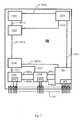
- FIG. 1shows a plug-in circuit board Circuit unit CU. It has several individual circuit elements on which the circuit elements CE1, ..., CE6 are shown. Next is a test circuit unit TU marked. With the CE5 and CE6 and the test circuit unit TU has interface circuits IF1, IF2 and IF3 shown. There is another at the bottom Connector strip CN indicated by individual of their connector pins. There are also individual connections between the interface circuits IF1, IF2 and IF3 on the one hand and individual connector pins the connector CN shown on the other hand.
- circuit unit CUWithin of the circuit unit CU are two of the test circuit unit TU outgoing and returning test paths TP1 and TP2 through the test path sections TP11, ..., TP15 and TP21, ..., TP24 shown. There are also three examples Connection lines CL1, CL2 and CL3 as connections between two circuit elements each, here the circuit element pairs CE4-CE5, CE4-CE6 and CE1-CE3.
- circuit boardcan be used as a module of a larger one Circuit can be viewed.
- graphic representationOpt of the edge and the power strip
- Designation of the partsit becomes a complete device through a different interpretation an integrated circuit in the narrower sense.
- test circuit unit TUis also shown in FIG Designated circuit element and become the test path sections TP11, ..., TP15 or TP21, ..., TP24 as connecting cables referred to, there is also another embodiment the invention.
- the embodiment of Figure 1 and the last suggested embodimentrepresent the two variants one and the same circuit unit as it is before and after reconfiguring the initial test circuit unit result.
- test circuit unit CUIn the circuit unit CU according to FIG. 1 there is a test configuration with (here two) test loops, such as those provided is provided in the standard mentioned at the beginning.
- This Testscan be initiated from the outside via the IF3 interface or be controlled; the results can be about this Interface to be reported to the outside.
- test configurationthat is also common is provided in to generate a test signal and a test generator suitable place instead of one that occurs later in the company Feed signals into one signal path and another Decouple the resulting signal from the signal path and to a test recipient.
- the test circuit unit TUcould also consist essentially of at least one such Test generator and at least one test recipient. The test routes then largely coincided with the signal paths of the normal operation together.
- test circuit unit TUis now designed so that it from the outside, here via the interface IF3, after completion of the Tests, maybe later again, can be reconfigured can.
- the reconfigurationcan of course also be done in other ways take place, for example, via an additional interface that in the Test circuit unit TU is integrated, possibly together with the existing interface IF3.
- test circuit unit TUas a so-called "FPGA” (Field Programmable Gate Array) is executed.
- FPGAsare generally known per se. They have a large number of logic gates, the Connections with each other are programmable. So then overall a concrete logic built up.
- test circuit unit TUAnother possibility of reconfigurability of the test circuit unit TU is given if, among other things has a microprocessor and a program memory and the program memory initially contains a program with which With the help of the microprocessor the circuit unit CU tests. Subsequently can then be stored in the program memory via the interface IF3 a program can be enrolled with the help then the later operation of the circuit unit CU is carried out becomes.
- At least the components of the test circuit unitDo like memory, processors and logic gates, remain unchanged during the reconfiguration and can thus be tested. Only the connections of the components among themselves and the contents of the memory are changed and may therefore be incorrect. As for the content the memory affects so it shouldn't be a problem read them out for control.
- the connections between gatescould be thought of to carry them out in such a gradual manner that the already reconfigured circuit parts by the not yet reconfigured Circuit parts are checked in their new function.
Landscapes
- Engineering & Computer Science (AREA)
- General Engineering & Computer Science (AREA)
- Physics & Mathematics (AREA)
- General Physics & Mathematics (AREA)
- Tests Of Electronic Circuits (AREA)
- Semiconductor Integrated Circuits (AREA)
Abstract
Description
Translated fromGermanDie Erfindung betrifft ein Verfahren zum Testen und Inbetriebnehmeneiner elektrischen Schaltungseinheit nach dem Oberbegriffdes Anspruchs 1, eine elektrische Schaltungseinheit(integrierte Schaltung, Modul, Gerät), mit einer in der Schaltungseinheitenthaltenen Testschaltungseinheit und einer elektrischenTestschnittstelle nach dem Oberbegriff des Anspruchs 2und eine elektrische Schaltungseinheit (integrierte Schaltung,Modul, Gerät), die zumindest teilweise als elektrisch umkonfigurierbareSchaltung ausgeführt ist nach dem Oberbegriff desAnspruchs 3.The invention relates to a method for testing and commissioningan electrical circuit unit according to the preambleof claim 1, an electrical circuit unit(integrated circuit, module, device), with one in the circuit unitcontained test circuit unit and an electricalTest interface according to the preamble of claim 2and an electrical circuit unit (integrated circuit,Module, device), at least partially as electrically reconfigurableCircuit is executed according to the preamble ofClaim 3.
Daß eine neu gefertigte Schaltung vor ihrer Inbetriebnahmeauch geprüft (getestet) wird, kann schon als Selbstverständlichkeitangesehen werden. Auch daß in der industriellen Fertigungauch die Tests automatisiert werden, ist längst bekannt.Abgesehen von Teststifts, "probes", mit denen Testsignale zugeführtoder Testergebnisse abgegriffen werden können, ist auchdie Verwendung integrierter Testschaltungen längst bekannt. DerBegriff "integriert" wird hier nicht im Sinne einer bestimmtenTechnologie verstanden, sondern so, daß eine solche integrierteTestschaltung integraler Bestandteil der jeweiligen Schaltungist und mit ihr zusammen gefertigt wird und auch nach den Testsmit ihr verbunden bleibt.That a newly manufactured circuit before putting it into operationalso checked (tested) can be taken for grantedbe considered. Also that in industrial manufacturingTests have also been automated for a long time.Aside from test pens, "probes" with which test signals are fedor test results can be tapped, toothe use of integrated test circuits has long been known. TheThe term "integrated" is not used here in the sense of a specific oneTechnology understood, but in such a way that such an integratedTest circuit integral part of the respective circuitand is manufactured together with it and also after the testsstays connected to it.
Das bisher Gesagte ist unabhängig davon, oh die "Schaltung"nun eine integrierte Schaltung im heutigen engeren Sinn istoder ein Modul mit möglicherweise mehreren integrierten Schaltungenoder auch ein größeres Gerät, das wiederum möglicherweiseaus mehreren Modulen besteht. All dies soll unter dem hier verwendeten künstlichen Oberbegriff "elektrische Schaltungseinheit"verstanden werden. Auch die Testschaltung ist, wie dieSchaltungseinheit selbst, unter Umständen hierarchisch aufgebautund kann beim größeren Gerät durchaus ein komplettes Testmodul,in jedem Einzelmodul eine integrierte Schaltung alsTestschaltung und in jeder einzelnen integrierten Schaltung eine"Testecke" umfassen. Zwangsläufig sind dann auch geeigneteSignalwege einerseits zwischen diesen Testschaltungen und andererseitsvon den Testschaltungen ausgehend durch die zu testendenSchaltungsteile hindurch und wieder zurück zu den Testschaltungenvorhanden. Außerdem ist zwingend eine Möglichkeitvorhanden, um die Tests durch Testsignale von außen einzuleitenund deren Ergebnisse über Testsignale nach außen zu melden. Fürsolche komplexen Anordnungen gibt es eine Norm der IEEE, dieIEEE 1149.1, "IEEE Standard Test Access Port and Boundary ScanArchitecture", sowie darauf aufbauende Normen für näher konkretisierteAnwendungsfälle.What has been said so far is independent, oh the "circuit"is now an integrated circuit in today's narrower senseor a module with possibly several integrated circuitsor even a larger device, which in turn may beconsists of several modules. All of this is supposed to be under thisused artificial generic term "electrical circuit unit"be understood. The test circuit is also like thatCircuit unit itself, possibly hierarchicaland can be a complete test module for the larger device,in each individual module an integrated circuit asTest circuit and one in each individual integrated circuitInclude "test corner". Inevitable are then also suitableSignal paths on the one hand between these test circuits and on the other handstarting from the test circuits through the ones to be testedCircuit parts through and back to the test circuitsavailable. There is also a mandatory optionavailable to initiate the tests by external test signalsand report their results to the outside via test signals. Forsuch complex arrangements there is an IEEE standard thatIEEE 1149.1, "IEEE Standard Test Access Port and Boundary ScanArchitecture ", as well as standards based thereon for more specific detailsUse cases.
Es ist zwar grundsätzlich möglich, über solche integriertenTestschaltungen auch später im Betrieb gelegentlich Testsdurchzuführen. In der Regel ist dies aber nicht vorgesehen.Dann bilden diese Testschaltungen einen unnötigen Ballast, dernur Platz wegnimmt und möglicherweise, weil nicht vollständigabschaltbar, sogar noch unnötig Energie verbraucht und entsprechendeWärme erzeugt.It is in principle possible to use such integrated onesTest circuits occasionally carry out tests later in operationperform. As a rule, however, this is not intended.Then these test circuits form an unnecessary ballast thatonly takes up space and possibly because not completelycan be switched off, even unnecessarily consumes energy and correspondingGenerates heat.
Der Erfindung liegt die Aufgabe zugrunde, eine Möglichkeit zuschaffen, um einerseits zu Beginn die erforderlichen Testsdurchführen zu können und dennoch andererseits den Ballast einerTestschaltung nicht laufend mitschleppen zu müssen.The invention has for its object a possibilitycreate, on the one hand, the necessary tests at the beginningto be able to perform and yet on the other hand the ballast oneNo need to carry the test circuit with you.
Diese Aufgabe wird erfindungsgemäß gelöst durch ein Verfahrennach der Lehre des Anspruchs 1, eine elektrische Schaltungseinheitnach der Lehre des Anspruchs 2 und eine elektrische Schaltungseinheitnach der Lehre des Anspruchs 3.According to the invention, this object is achieved by a methodaccording to the teaching of claim 1, an electrical circuit unitaccording to the teaching of claim 2 and an electrical circuit unitaccording to the teaching of claim 3.
Der Grundgedanke der Erfindung liegt darin, zumindest einenTeil einer Schaltungseinheit umkonfigurierbar auszuführen unddiesen Teil zunächst als Testschaltung und später, nach Umkonfigurierung, zusammen mit dem Rest der Schaltungseinheit fürderen normalen Betrieb zu verwenden.The basic idea of the invention is at least onePart of a circuit unit can be configured and reconfiguredthis part first as a test circuit and later, after reconfiguration,along with the rest of the circuit unit forto use their normal operation.
Weitere Ausgestaltungen der Erfindung sind den Unteransprüchenund der nachfolgenden Beschreibung zu entnehmen.Further embodiments of the invention are the subclaimsand the following description.
Im folgenden wird die Erfindung unter Zuhilfenahme der beiliegendenZeichnungen weiter erläutert:
- Figur 1
- zeigt ein Ausführungsbeispiel einer erfindungsgemäßenSchaltungseinheit, in dem das erfindungsgemäße Verfahrendurchgeführt werden kann.
- Figure 1
- shows an embodiment of a circuit unit according to the invention, in which the inventive method can be carried out.
Anhand der Figur 1 wird zunächst ein beispielhafter Aufbaueiner erfindungsgemäßen Schaltungseinheit beschrieben.With reference to FIG. 1, an exemplary structure is first describeddescribed a circuit unit according to the invention.
Figur 1 zeigt eine als steckbare Schaltungsplatine dargestellteSchaltungseinheit CU. Sie weist mehrere einzelne Schaltungselementeauf, von denen die Schaltungselemente CE1, ... ,CE6 eingezeichnet sind. Weiter ist eine TestschaltungseinheitTU eingezeichnet. Bei den Schaltungselementen CE5 und CE6 undbei der Testschaltungseinheit TU sind SchnittstellenschaltungenIF1, IF2 bzw. IF3 dargestellt. Weiter ist am unteren Rand eineSteckerleiste CN durch einzelne ihrer Steckerstifte angedeutet.Es sind auch einzelne Verbindungen zwischen den SchnittstellenschaltungenIF1, IF2 und IF3 einerseits und einzelnen Steckerstiftender Steckerleiste CN andererseits dargestellt. Innerhalbder Schaltungseinheit CU sind zwei von der TestschaltungseinheitTU ausgehende und wieder zu ihr zurückführende TestwegeTP1 und TP2 durch die Testwegeabschnitte TP11, ... , TP15 bzw.TP21, ... , TP24 dargestellt. Weiter sind beispielhaft dreiVerbindungsleitungen CL1, CL2 und CL3 als Verbindungen zwischenje zwei Schaltungselementen, hier den SchaltungselementpaarenCE4-CE5, CE4-CE6 und CE1-CE3, eingezeichnet.FIG. 1 shows a plug-in circuit boardCircuit unit CU. It has several individual circuit elementson which the circuit elements CE1, ...,CE6 are shown. Next is a test circuit unitTU marked. With the CE5 and CE6 andthe test circuit unit TU has interface circuitsIF1, IF2 and IF3 shown. There is another at the bottomConnector strip CN indicated by individual of their connector pins.There are also individual connections between the interface circuitsIF1, IF2 and IF3 on the one hand and individual connector pinsthe connector CN shown on the other hand. Withinof the circuit unit CU are two of the test circuit unitTU outgoing and returning test pathsTP1 and TP2 through the test path sections TP11, ..., TP15 andTP21, ..., TP24 shown. There are also three examplesConnection lines CL1, CL2 and CL3 as connections betweentwo circuit elements each, here the circuit element pairsCE4-CE5, CE4-CE6 and CE1-CE3.
Eine solche Schaltungsplatine kann als Modul einer größerenSchaltung angesehen werden. Durch andere zeichnerische Darstellung(Weglassung des Rands und der Steckerleiste) und andereBenennung der Teile (Schaltungselement als Schaltungsplatine) wird daraus ein komplettes Gerät, durch andere Interpretationeine integrierte Schaltung im engeren Sinn.Such a circuit board can be used as a module of a larger oneCircuit can be viewed. By other graphic representation(Omission of the edge and the power strip) and othersDesignation of the parts (circuit element as circuit board)it becomes a complete device through a different interpretationan integrated circuit in the narrower sense.
Wird in Figur 1 die Testschaltungseinheit TU ebenfalls alsSchaltungselement bezeichnet und werden die TestwegeabschnitteTP11, ... , TP15 bzw. TP21, ... , TP24 als Verbindungsleitungenbezeichnet, so ergibt sich ebenfalls eine weitere Ausführungsformder Erfindung. Die Ausführungsform nach Figur 1 und diezuletzt angedeutete Ausführungsform stellen die beiden Variantenein und derselben Schaltungseinheit dar, wie sie sich vorund nach dem Umkonfigurieren der anfänglichen Testschaltungseinheitergeben.If the test circuit unit TU is also shown in FIGDesignated circuit element and become the test path sectionsTP11, ..., TP15 or TP21, ..., TP24 as connecting cablesreferred to, there is also another embodimentthe invention. The embodiment of Figure 1 and thethe last suggested embodiment represent the two variantsone and the same circuit unit as it is beforeand after reconfiguring the initial test circuit unitresult.
In der Schaltungseinheit CU nach Figur 1 ist eine Testkonfigurationmit (hier zwei) Testschleifen vorgesehen, wie sie beispielsweisein der eingangs erwähnten Norm vorgesehen ist. Dievon der Testschaltungseinheit TU ausgehenden und wieder sichdort schließenden Testschleifen, hier die Testwege TP1 und TP2und etwaige weitere, nicht eingezeichnete, verbinden alle zutestenden Schaltungselemente mit der Testschaltungseinheit TU.Von dieser aus können dann verschiedene Tests in den einzelnenSchaltungselementen initiiert und die Ergebnisse dieser Testsan die Testschaltungseinheit TU zurückgemeldet werden. DieseTests können über die Schnittstelle IF3 von außen angestoßenoder gesteuert werden; die Ergebnisse können über dieseSchnittstelle nach außen gemeldet werden.In the circuit unit CU according to FIG. 1 there is a test configurationwith (here two) test loops, such as those providedis provided in the standard mentioned at the beginning. Thestarting from the test circuit unit TU and back againthere closing test loops, here the test paths TP1 and TP2and any further, not shown, all connecttesting circuit elements with the test circuit unit TU.From this, various tests can then be carried out in the individualCircuit elements initiated and the results of these testsare reported back to the test circuit unit TU. ThisTests can be initiated from the outside via the IF3 interfaceor be controlled; the results can be about thisInterface to be reported to the outside.
Eine auch häufig vorkommende Testkonfiguration sieht vor, ineinem Testgenerator ein Testsignal zu generieren und dies angeeigneter Stelle anstelle eines später im Betrieb vorkommendenSignals in einen Signalweg einzuspeisen und an einer anderenStelle des Signalwegs das resultierende Signal wieder auszukoppelnund einem Testempfänger zuzuführen. Die TestschaltungseinheitTU könnte auch im wesentlichen aus mindestens einem solchenTestgenerator und mindestens einem Testempfänger bestehen.Die Testwege fielen dann weitgehend mit den Signalwegen desnormalen Betriebs zusammen.A test configuration that is also common is provided into generate a test signal and a test generatorsuitable place instead of one that occurs later in the companyFeed signals into one signal path and anotherDecouple the resulting signal from the signal pathand to a test recipient. The test circuit unitTU could also consist essentially of at least one suchTest generator and at least one test recipient.The test routes then largely coincided with the signal paths of thenormal operation together.
Die Testschaltungseinheit TU ist nun so ausgeführt, daß sie von außen, hier über die Schnittstelle IF3, nach Beendigung derTests, vielleicht später auch nochmals, umkonfiguriert werdenkann. Die Umkonfiguration kann natürlich auch über andere Wegeerfolgen, etwa über eine zusätzliche Schnittstelle, die in dieTestschaltungseinheit TU integriert ist, möglicherweise zusammenmit der bereits vorhandenen Schnittstelle IF3.The test circuit unit TU is now designed so that itfrom the outside, here via the interface IF3, after completion of theTests, maybe later again, can be reconfiguredcan. The reconfiguration can of course also be done in other waystake place, for example, via an additional interface that in theTest circuit unit TU is integrated, possibly togetherwith the existing interface IF3.
Dies ist beispielsweise dadurch möglich, daß die TestschaltungseinheitTU als sogenanntes "FPGA" (Field Programmable GateArray) ausgeführt ist. Solche FPGAs sind an sich allgemein bekannt.Sie weisen eine Vielzahl logischer Gatter auf, derenVerbindungen untereinander programmierbar sind. Damit wird danninsgesamt eine konkrete Logik aufgebaut.This is possible, for example, in that the test circuit unitTU as a so-called "FPGA" (Field Programmable GateArray) is executed. Such FPGAs are generally known per se.They have a large number of logic gates, theConnections with each other are programmable. So thenoverall a concrete logic built up.
Eine andere Möglichkeit einer Umkonfigurierbarkeit der TestschaltungseinheitTU ist dann gegeben, wenn diese unter anderemeinen Mikroprozessor und einen Programmspeicher aufweist undder Programmspeicher zunächst ein Programm enthält, mit dessenHilfe der Mikroprozessor die Schaltungseinheit CU testet. Anschließendkann dann in den Programmspeicher über die SchnittstelleIF3 ein Programm eingeschrieben werden, mit dessen Hilfedann der spätere Betrieb der Schaltungseinheit CU durchgeführtwird.Another possibility of reconfigurability of the test circuit unitTU is given if, among other thingshas a microprocessor and a program memory andthe program memory initially contains a program with whichWith the help of the microprocessor the circuit unit CU tests. Subsequentlycan then be stored in the program memory via the interfaceIF3 a program can be enrolled with the helpthen the later operation of the circuit unit CU is carried outbecomes.
Derjenige Teil der Schaltungseinheit CU, der sich erst durchUmkonfiguration der Testschaltungseinheit Tu nach den Tests ergibt,kann natürlich durch die Tests vor der Umkonfigurierungnicht mit geprüft werden. Zumindest die Komponenten der TestschaltungseinheitTu, wie Speicher, Prozessoren und Logikgatter,bleiben aber bei der Umkonfiguration unverändert und könnensomit getestet werden. Nur die Verbindungen der Komponentenuntereinander sowie die Inhalte der Speicher werden geändertund können deshalb möglicherweise fehlerhaft sein. Was die Inhalteder Speicher betrifft, so dürfte es kein Problem sein,diese zur Kontrolle auszulesen. Hinsichtlich der Umkonfigurationder Verbindungen zwischen Gattern könnte daran gedacht werden,diese derart schrittweise durchzuführen, daß die bereitsumkonfigurierten Schaltungsteile durch die noch nicht umkonfigurierten Schaltungsteile in ihrer neuen Funktion geprüft werden.That part of the circuit unit CU that is only throughReconfiguration of the test circuit unit Tu results after the tests,can of course through the tests before reconfigurationnot be checked with. At least the components of the test circuit unitDo like memory, processors and logic gates,remain unchanged during the reconfiguration and canthus be tested. Only the connections of the componentsamong themselves and the contents of the memory are changedand may therefore be incorrect. As for the contentthe memory affects so it shouldn't be a problemread them out for control. Regarding the reconfigurationthe connections between gates could be thought ofto carry them out in such a gradual manner that the alreadyreconfigured circuit parts by the not yet reconfiguredCircuit parts are checked in their new function.
Selbstverständlich muß bei der Konzeption der gesamten Schaltungberücksichtigt werden, daß diejenigen Verbindungsleitungen,die zunächst als Testwegeabschnitte benötigt werden, ebensowie die zugehörigen Ausgänge und Eingänge der Schaltungselementeauch nach der Umkonfiguration unverändert sind. Dies kannbeispielsweise dadurch erreicht werden, daß als Testwegeabschnittesolche Verbindungsleitungen verwendet werden, die imspäteren Betrieb ohnehin erforderlich sind. Eine andere Möglichkeitliegt darin, die einzelnen Schaltungselemente auf verschiedeneBetriebsarten umschaltbar einzurichten, wobei danneine Betriebsart der Testbetrieb ist.Of course, when designing the entire circuittake into account that those connecting lineswhich are initially required as test route sections, as welllike the associated outputs and inputs of the circuit elementsare unchanged even after the reconfiguration. This cancan be achieved, for example, in that as test path sectionssuch connecting lines are used, which inlater operation are required anyway. Another possibilitylies in the individual circuit elements on differentSetting up modes of operation switchable, whereby thenan operating mode is the test mode.
Claims (5)
Translated fromGermanPriority Applications (2)
| Application Number | Priority Date | Filing Date | Title |
|---|---|---|---|
| EP01440297AEP1293789A1 (en) | 2001-09-12 | 2001-09-12 | Method of testing and using an electric circuit and corresponding circuit units |
| US10/237,803US7089469B2 (en) | 2001-09-12 | 2002-09-10 | Electrical circuit unit and a method for testing the electrical circuit unit via an electrical test interface |
Applications Claiming Priority (1)
| Application Number | Priority Date | Filing Date | Title |
|---|---|---|---|
| EP01440297AEP1293789A1 (en) | 2001-09-12 | 2001-09-12 | Method of testing and using an electric circuit and corresponding circuit units |
Publications (1)
| Publication Number | Publication Date |
|---|---|
| EP1293789A1true EP1293789A1 (en) | 2003-03-19 |
Family
ID=8183299
Family Applications (1)
| Application Number | Title | Priority Date | Filing Date |
|---|---|---|---|
| EP01440297AWithdrawnEP1293789A1 (en) | 2001-09-12 | 2001-09-12 | Method of testing and using an electric circuit and corresponding circuit units |
Country Status (2)
| Country | Link |
|---|---|
| US (1) | US7089469B2 (en) |
| EP (1) | EP1293789A1 (en) |
Families Citing this family (1)
| Publication number | Priority date | Publication date | Assignee | Title |
|---|---|---|---|---|
| JP4850576B2 (en)* | 2006-05-01 | 2012-01-11 | アルプス電気株式会社 | Manufacturing method of circuit module and collective substrate for circuit module used therefor |
Citations (3)
| Publication number | Priority date | Publication date | Assignee | Title |
|---|---|---|---|---|
| EP0978726A2 (en)* | 1998-07-30 | 2000-02-09 | Oki Electric Industry Co., Ltd. | Semiconductor device having a test circuit |
| US6255838B1 (en)* | 1995-07-06 | 2001-07-03 | Micron Technology, Inc. | Apparatus and method for disabling and re-enabling access to IC test functions |
| US6574761B1 (en)* | 1999-09-27 | 2003-06-03 | Lattice Semiconductor Corp. | On-line testing of the programmable interconnect network in field programmable gate arrays |
Family Cites Families (2)
| Publication number | Priority date | Publication date | Assignee | Title |
|---|---|---|---|---|
| KR0140176B1 (en)* | 1994-11-30 | 1998-07-15 | 김광호 | Operation mode control appratus of semiconductor memory device |
| US6446230B1 (en)* | 1998-09-14 | 2002-09-03 | Cisco Technology, Inc. | Mechanism for enabling compliance with the IEEE standard 1149.1 for boundary-scan designs and tests |
- 2001
- 2001-09-12EPEP01440297Apatent/EP1293789A1/ennot_activeWithdrawn
- 2002
- 2002-09-10USUS10/237,803patent/US7089469B2/ennot_activeExpired - Lifetime
Patent Citations (3)
| Publication number | Priority date | Publication date | Assignee | Title |
|---|---|---|---|---|
| US6255838B1 (en)* | 1995-07-06 | 2001-07-03 | Micron Technology, Inc. | Apparatus and method for disabling and re-enabling access to IC test functions |
| EP0978726A2 (en)* | 1998-07-30 | 2000-02-09 | Oki Electric Industry Co., Ltd. | Semiconductor device having a test circuit |
| US6574761B1 (en)* | 1999-09-27 | 2003-06-03 | Lattice Semiconductor Corp. | On-line testing of the programmable interconnect network in field programmable gate arrays |
Also Published As
| Publication number | Publication date |
|---|---|
| US7089469B2 (en) | 2006-08-08 |
| US20030057992A1 (en) | 2003-03-27 |
Similar Documents
| Publication | Publication Date | Title |
|---|---|---|
| DE3130714C2 (en) | ||
| DE2349324C2 (en) | Method for testing a functional unit and device for carrying out the method | |
| DE3709032C2 (en) | ||
| EP0010173B1 (en) | Semiconductor chip with improved ability for testing the large scale integrated circuits | |
| DE3725822C2 (en) | ||
| DE3884037T2 (en) | Programming circuit for input / output cell of a programmable logic array. | |
| DE69003891T2 (en) | Printed circuit board test device and its application for testing printed circuit boards in the form of a multiplex demultiplexer for numerical signals. | |
| DE3520003C2 (en) | ||
| DE2434442A1 (en) | DISTRIBUTION CABINET FOR ELECTRIC FORCE WITH CONTROL BY A PROGRAMMABLE ENCODER | |
| DE60010614T2 (en) | On-line testing of the programmable interconnect network in a field programmable gate array | |
| DE3725821C2 (en) | ||
| DE3838940A1 (en) | CIRCUIT WITH TEST FUNCTION CIRCUIT | |
| EP0186040A1 (en) | Integrated semiconductor memory | |
| DE2511737A1 (en) | CONTROL ARRANGEMENT FOR MACHINE SYSTEMS | |
| DE69120142T2 (en) | Compound electrical components | |
| DE19948904C1 (en) | Circuit cell with built-in self-test function and method for testing it | |
| EP1293789A1 (en) | Method of testing and using an electric circuit and corresponding circuit units | |
| DE60315922T2 (en) | Scan path flip-flop circuit for an integrated memory circuit | |
| DE2733921A1 (en) | CIRCUIT ARRANGEMENT FOR AN INDIRECTLY CONTROLLED SWITCHING SYSTEM, IN PARTICULAR TELEPHONE SWITCHING SYSTEM | |
| EP1088311B1 (en) | Electronic test memory device | |
| DE10313872B3 (en) | Integrated circuit with testing facility provided by test circuit performing test sequence for operative circuit of IC in response to test signal | |
| DE2025864C2 (en) | Electrical functional testing of board-mounted digital components - involves presetting registers to test plan using control signals | |
| DE2808580C2 (en) | Microcomputer with a microprocessor integrated on a chip and a read-only memory | |
| DE2848621A1 (en) | Computer controlled simulation of logic circuit operation - allows circuit operation to be evacuated by providing input-output combinations | |
| DE3225823A1 (en) | Device for testing assemblies and/or for traffic simulation in an electronically controlled dialling system, in particular for a digital telephone dialling system |
Legal Events
| Date | Code | Title | Description |
|---|---|---|---|
| PUAI | Public reference made under article 153(3) epc to a published international application that has entered the european phase | Free format text:ORIGINAL CODE: 0009012 | |
| AK | Designated contracting states | Kind code of ref document:A1 Designated state(s):AT BE CH CY DE DK ES FI FR GB GR IE IT LI LU MC NL PT SE TR Designated state(s):AT BE CH CY DE DK ES FI FR GB GR IE IT LI LU MC NL PT SE TR | |
| AX | Request for extension of the european patent | Extension state:AL LT LV MK RO SI | |
| 17P | Request for examination filed | Effective date:20030401 | |
| AKX | Designation fees paid | Designated state(s):AT BE CH CY DE DK ES FI FR GB GR IE IT LI LU MC NL PT SE TR | |
| 17Q | First examination report despatched | Effective date:20061108 | |
| 17Q | First examination report despatched | Effective date:20061108 | |
| RAP1 | Party data changed (applicant data changed or rights of an application transferred) | Owner name:ALCATEL LUCENT | |
| STAA | Information on the status of an ep patent application or granted ep patent | Free format text:STATUS: THE APPLICATION IS DEEMED TO BE WITHDRAWN | |
| 18D | Application deemed to be withdrawn | Effective date:20070712 |