EP1293180A1 - Spinal implant with adjustable height - Google Patents
Spinal implant with adjustable heightDownload PDFInfo
- Publication number
- EP1293180A1 EP1293180A1EP01120459AEP01120459AEP1293180A1EP 1293180 A1EP1293180 A1EP 1293180A1EP 01120459 AEP01120459 AEP 01120459AEP 01120459 AEP01120459 AEP 01120459AEP 1293180 A1EP1293180 A1EP 1293180A1
- Authority
- EP
- European Patent Office
- Prior art keywords
- implant
- height
- partners
- adjustable height
- implants
- Prior art date
- Legal status (The legal status is an assumption and is not a legal conclusion. Google has not performed a legal analysis and makes no representation as to the accuracy of the status listed.)
- Granted
Links
- 239000007943implantSubstances0.000titleclaimsabstractdescription50
- 125000006850spacer groupChemical group0.000claimsabstractdescription6
- 238000010276constructionMethods0.000claimsdescription2
- 238000001356surgical procedureMethods0.000description4
- 238000004140cleaningMethods0.000description2
- 206010010356Congenital anomalyDiseases0.000description1
- 208000003618Intervertebral Disc DisplacementDiseases0.000description1
- 206010050296Intervertebral disc protrusionDiseases0.000description1
- 208000024777Prion diseaseDiseases0.000description1
- 208000020307Spinal diseaseDiseases0.000description1
- 230000005540biological transmissionEffects0.000description1
- 210000000988bone and boneAnatomy0.000description1
- 230000001419dependent effectEffects0.000description1
- 201000010099diseaseDiseases0.000description1
- 208000037265diseases, disorders, signs and symptomsDiseases0.000description1
- 238000006073displacement reactionMethods0.000description1
- 208000015181infectious diseaseDiseases0.000description1
- 238000009434installationMethods0.000description1
- 230000007246mechanismEffects0.000description1
- 230000005541medical transmissionEffects0.000description1
- 230000037361pathwayEffects0.000description1
- 230000036316preloadEffects0.000description1
- 102000004169proteins and genesHuman genes0.000description1
- 108090000623proteins and genesProteins0.000description1
- 230000003252repetitive effectEffects0.000description1
- 230000006641stabilisationEffects0.000description1
- 238000011105stabilizationMethods0.000description1
- 230000003068static effectEffects0.000description1
- 230000001954sterilising effectEffects0.000description1
- 238000004659sterilization and disinfectionMethods0.000description1
- 238000011477surgical interventionMethods0.000description1
Images

Classifications
- A—HUMAN NECESSITIES
- A61—MEDICAL OR VETERINARY SCIENCE; HYGIENE
- A61F—FILTERS IMPLANTABLE INTO BLOOD VESSELS; PROSTHESES; DEVICES PROVIDING PATENCY TO, OR PREVENTING COLLAPSING OF, TUBULAR STRUCTURES OF THE BODY, e.g. STENTS; ORTHOPAEDIC, NURSING OR CONTRACEPTIVE DEVICES; FOMENTATION; TREATMENT OR PROTECTION OF EYES OR EARS; BANDAGES, DRESSINGS OR ABSORBENT PADS; FIRST-AID KITS
- A61F2/00—Filters implantable into blood vessels; Prostheses, i.e. artificial substitutes or replacements for parts of the body; Appliances for connecting them with the body; Devices providing patency to, or preventing collapsing of, tubular structures of the body, e.g. stents
- A61F2/02—Prostheses implantable into the body
- A61F2/30—Joints
- A61F2/44—Joints for the spine, e.g. vertebrae, spinal discs
- A61F2/442—Intervertebral or spinal discs, e.g. resilient
- A—HUMAN NECESSITIES
- A61—MEDICAL OR VETERINARY SCIENCE; HYGIENE
- A61F—FILTERS IMPLANTABLE INTO BLOOD VESSELS; PROSTHESES; DEVICES PROVIDING PATENCY TO, OR PREVENTING COLLAPSING OF, TUBULAR STRUCTURES OF THE BODY, e.g. STENTS; ORTHOPAEDIC, NURSING OR CONTRACEPTIVE DEVICES; FOMENTATION; TREATMENT OR PROTECTION OF EYES OR EARS; BANDAGES, DRESSINGS OR ABSORBENT PADS; FIRST-AID KITS
- A61F2/00—Filters implantable into blood vessels; Prostheses, i.e. artificial substitutes or replacements for parts of the body; Appliances for connecting them with the body; Devices providing patency to, or preventing collapsing of, tubular structures of the body, e.g. stents
- A61F2/02—Prostheses implantable into the body
- A61F2/30—Joints
- A61F2/44—Joints for the spine, e.g. vertebrae, spinal discs
- A—HUMAN NECESSITIES
- A61—MEDICAL OR VETERINARY SCIENCE; HYGIENE
- A61F—FILTERS IMPLANTABLE INTO BLOOD VESSELS; PROSTHESES; DEVICES PROVIDING PATENCY TO, OR PREVENTING COLLAPSING OF, TUBULAR STRUCTURES OF THE BODY, e.g. STENTS; ORTHOPAEDIC, NURSING OR CONTRACEPTIVE DEVICES; FOMENTATION; TREATMENT OR PROTECTION OF EYES OR EARS; BANDAGES, DRESSINGS OR ABSORBENT PADS; FIRST-AID KITS
- A61F2/00—Filters implantable into blood vessels; Prostheses, i.e. artificial substitutes or replacements for parts of the body; Appliances for connecting them with the body; Devices providing patency to, or preventing collapsing of, tubular structures of the body, e.g. stents
- A61F2/02—Prostheses implantable into the body
- A61F2/30—Joints
- A61F2/30721—Accessories
- A61F2/30724—Spacers for centering an implant in a bone cavity, e.g. in a cement-receiving cavity
- A—HUMAN NECESSITIES
- A61—MEDICAL OR VETERINARY SCIENCE; HYGIENE
- A61F—FILTERS IMPLANTABLE INTO BLOOD VESSELS; PROSTHESES; DEVICES PROVIDING PATENCY TO, OR PREVENTING COLLAPSING OF, TUBULAR STRUCTURES OF THE BODY, e.g. STENTS; ORTHOPAEDIC, NURSING OR CONTRACEPTIVE DEVICES; FOMENTATION; TREATMENT OR PROTECTION OF EYES OR EARS; BANDAGES, DRESSINGS OR ABSORBENT PADS; FIRST-AID KITS
- A61F2/00—Filters implantable into blood vessels; Prostheses, i.e. artificial substitutes or replacements for parts of the body; Appliances for connecting them with the body; Devices providing patency to, or preventing collapsing of, tubular structures of the body, e.g. stents
- A61F2/02—Prostheses implantable into the body
- A61F2/30—Joints
- A61F2/46—Special tools for implanting artificial joints
- A61F2/4603—Special tools for implanting artificial joints for insertion or extraction of endoprosthetic joints or of accessories thereof
- A61F2/4611—Special tools for implanting artificial joints for insertion or extraction of endoprosthetic joints or of accessories thereof of spinal prostheses
- A—HUMAN NECESSITIES
- A61—MEDICAL OR VETERINARY SCIENCE; HYGIENE
- A61F—FILTERS IMPLANTABLE INTO BLOOD VESSELS; PROSTHESES; DEVICES PROVIDING PATENCY TO, OR PREVENTING COLLAPSING OF, TUBULAR STRUCTURES OF THE BODY, e.g. STENTS; ORTHOPAEDIC, NURSING OR CONTRACEPTIVE DEVICES; FOMENTATION; TREATMENT OR PROTECTION OF EYES OR EARS; BANDAGES, DRESSINGS OR ABSORBENT PADS; FIRST-AID KITS
- A61F2/00—Filters implantable into blood vessels; Prostheses, i.e. artificial substitutes or replacements for parts of the body; Appliances for connecting them with the body; Devices providing patency to, or preventing collapsing of, tubular structures of the body, e.g. stents
- A61F2/02—Prostheses implantable into the body
- A61F2/30—Joints
- A61F2002/30001—Additional features of subject-matter classified in A61F2/28, A61F2/30 and subgroups thereof
- A61F2002/30108—Shapes
- A61F2002/3011—Cross-sections or two-dimensional shapes
- A61F2002/30138—Convex polygonal shapes
- A61F2002/30143—Convex polygonal shapes hexagonal
- A—HUMAN NECESSITIES
- A61—MEDICAL OR VETERINARY SCIENCE; HYGIENE
- A61F—FILTERS IMPLANTABLE INTO BLOOD VESSELS; PROSTHESES; DEVICES PROVIDING PATENCY TO, OR PREVENTING COLLAPSING OF, TUBULAR STRUCTURES OF THE BODY, e.g. STENTS; ORTHOPAEDIC, NURSING OR CONTRACEPTIVE DEVICES; FOMENTATION; TREATMENT OR PROTECTION OF EYES OR EARS; BANDAGES, DRESSINGS OR ABSORBENT PADS; FIRST-AID KITS
- A61F2/00—Filters implantable into blood vessels; Prostheses, i.e. artificial substitutes or replacements for parts of the body; Appliances for connecting them with the body; Devices providing patency to, or preventing collapsing of, tubular structures of the body, e.g. stents
- A61F2/02—Prostheses implantable into the body
- A61F2/30—Joints
- A61F2002/30001—Additional features of subject-matter classified in A61F2/28, A61F2/30 and subgroups thereof
- A61F2002/30108—Shapes
- A61F2002/3011—Cross-sections or two-dimensional shapes
- A61F2002/30138—Convex polygonal shapes
- A61F2002/30146—Convex polygonal shapes octagonal
- A—HUMAN NECESSITIES
- A61—MEDICAL OR VETERINARY SCIENCE; HYGIENE
- A61F—FILTERS IMPLANTABLE INTO BLOOD VESSELS; PROSTHESES; DEVICES PROVIDING PATENCY TO, OR PREVENTING COLLAPSING OF, TUBULAR STRUCTURES OF THE BODY, e.g. STENTS; ORTHOPAEDIC, NURSING OR CONTRACEPTIVE DEVICES; FOMENTATION; TREATMENT OR PROTECTION OF EYES OR EARS; BANDAGES, DRESSINGS OR ABSORBENT PADS; FIRST-AID KITS
- A61F2/00—Filters implantable into blood vessels; Prostheses, i.e. artificial substitutes or replacements for parts of the body; Appliances for connecting them with the body; Devices providing patency to, or preventing collapsing of, tubular structures of the body, e.g. stents
- A61F2/02—Prostheses implantable into the body
- A61F2/30—Joints
- A61F2002/30001—Additional features of subject-matter classified in A61F2/28, A61F2/30 and subgroups thereof
- A61F2002/30316—The prosthesis having different structural features at different locations within the same prosthesis; Connections between prosthetic parts; Special structural features of bone or joint prostheses not otherwise provided for
- A61F2002/30329—Connections or couplings between prosthetic parts, e.g. between modular parts; Connecting elements
- A61F2002/30331—Connections or couplings between prosthetic parts, e.g. between modular parts; Connecting elements made by longitudinally pushing a protrusion into a complementarily-shaped recess, e.g. held by friction fit
- A61F2002/30362—Connections or couplings between prosthetic parts, e.g. between modular parts; Connecting elements made by longitudinally pushing a protrusion into a complementarily-shaped recess, e.g. held by friction fit with possibility of relative movement between the protrusion and the recess
- A61F2002/30364—Rotation about the common longitudinal axis
- A—HUMAN NECESSITIES
- A61—MEDICAL OR VETERINARY SCIENCE; HYGIENE
- A61F—FILTERS IMPLANTABLE INTO BLOOD VESSELS; PROSTHESES; DEVICES PROVIDING PATENCY TO, OR PREVENTING COLLAPSING OF, TUBULAR STRUCTURES OF THE BODY, e.g. STENTS; ORTHOPAEDIC, NURSING OR CONTRACEPTIVE DEVICES; FOMENTATION; TREATMENT OR PROTECTION OF EYES OR EARS; BANDAGES, DRESSINGS OR ABSORBENT PADS; FIRST-AID KITS
- A61F2/00—Filters implantable into blood vessels; Prostheses, i.e. artificial substitutes or replacements for parts of the body; Appliances for connecting them with the body; Devices providing patency to, or preventing collapsing of, tubular structures of the body, e.g. stents
- A61F2/02—Prostheses implantable into the body
- A61F2/30—Joints
- A61F2002/30001—Additional features of subject-matter classified in A61F2/28, A61F2/30 and subgroups thereof
- A61F2002/30316—The prosthesis having different structural features at different locations within the same prosthesis; Connections between prosthetic parts; Special structural features of bone or joint prostheses not otherwise provided for
- A61F2002/30329—Connections or couplings between prosthetic parts, e.g. between modular parts; Connecting elements
- A61F2002/30383—Connections or couplings between prosthetic parts, e.g. between modular parts; Connecting elements made by laterally inserting a protrusion, e.g. a rib into a complementarily-shaped groove
- A61F2002/3039—Connections or couplings between prosthetic parts, e.g. between modular parts; Connecting elements made by laterally inserting a protrusion, e.g. a rib into a complementarily-shaped groove with possibility of relative movement of the rib within the groove
- A61F2002/30392—Rotation
- A—HUMAN NECESSITIES
- A61—MEDICAL OR VETERINARY SCIENCE; HYGIENE
- A61F—FILTERS IMPLANTABLE INTO BLOOD VESSELS; PROSTHESES; DEVICES PROVIDING PATENCY TO, OR PREVENTING COLLAPSING OF, TUBULAR STRUCTURES OF THE BODY, e.g. STENTS; ORTHOPAEDIC, NURSING OR CONTRACEPTIVE DEVICES; FOMENTATION; TREATMENT OR PROTECTION OF EYES OR EARS; BANDAGES, DRESSINGS OR ABSORBENT PADS; FIRST-AID KITS
- A61F2/00—Filters implantable into blood vessels; Prostheses, i.e. artificial substitutes or replacements for parts of the body; Appliances for connecting them with the body; Devices providing patency to, or preventing collapsing of, tubular structures of the body, e.g. stents
- A61F2/02—Prostheses implantable into the body
- A61F2/30—Joints
- A61F2002/30001—Additional features of subject-matter classified in A61F2/28, A61F2/30 and subgroups thereof
- A61F2002/30316—The prosthesis having different structural features at different locations within the same prosthesis; Connections between prosthetic parts; Special structural features of bone or joint prostheses not otherwise provided for
- A61F2002/30535—Special structural features of bone or joint prostheses not otherwise provided for
- A61F2002/30537—Special structural features of bone or joint prostheses not otherwise provided for adjustable
- A61F2002/3055—Special structural features of bone or joint prostheses not otherwise provided for adjustable for adjusting length
- A—HUMAN NECESSITIES
- A61—MEDICAL OR VETERINARY SCIENCE; HYGIENE
- A61F—FILTERS IMPLANTABLE INTO BLOOD VESSELS; PROSTHESES; DEVICES PROVIDING PATENCY TO, OR PREVENTING COLLAPSING OF, TUBULAR STRUCTURES OF THE BODY, e.g. STENTS; ORTHOPAEDIC, NURSING OR CONTRACEPTIVE DEVICES; FOMENTATION; TREATMENT OR PROTECTION OF EYES OR EARS; BANDAGES, DRESSINGS OR ABSORBENT PADS; FIRST-AID KITS
- A61F2/00—Filters implantable into blood vessels; Prostheses, i.e. artificial substitutes or replacements for parts of the body; Appliances for connecting them with the body; Devices providing patency to, or preventing collapsing of, tubular structures of the body, e.g. stents
- A61F2/02—Prostheses implantable into the body
- A61F2/30—Joints
- A61F2002/30001—Additional features of subject-matter classified in A61F2/28, A61F2/30 and subgroups thereof
- A61F2002/30316—The prosthesis having different structural features at different locations within the same prosthesis; Connections between prosthetic parts; Special structural features of bone or joint prostheses not otherwise provided for
- A61F2002/30535—Special structural features of bone or joint prostheses not otherwise provided for
- A61F2002/30599—Special structural features of bone or joint prostheses not otherwise provided for stackable
- A—HUMAN NECESSITIES
- A61—MEDICAL OR VETERINARY SCIENCE; HYGIENE
- A61F—FILTERS IMPLANTABLE INTO BLOOD VESSELS; PROSTHESES; DEVICES PROVIDING PATENCY TO, OR PREVENTING COLLAPSING OF, TUBULAR STRUCTURES OF THE BODY, e.g. STENTS; ORTHOPAEDIC, NURSING OR CONTRACEPTIVE DEVICES; FOMENTATION; TREATMENT OR PROTECTION OF EYES OR EARS; BANDAGES, DRESSINGS OR ABSORBENT PADS; FIRST-AID KITS
- A61F2/00—Filters implantable into blood vessels; Prostheses, i.e. artificial substitutes or replacements for parts of the body; Appliances for connecting them with the body; Devices providing patency to, or preventing collapsing of, tubular structures of the body, e.g. stents
- A61F2/02—Prostheses implantable into the body
- A61F2/30—Joints
- A61F2/30767—Special external or bone-contacting surface, e.g. coating for improving bone ingrowth
- A61F2/30771—Special external or bone-contacting surface, e.g. coating for improving bone ingrowth applied in original prostheses, e.g. holes or grooves
- A61F2002/30795—Blind bores, e.g. of circular cross-section
- A—HUMAN NECESSITIES
- A61—MEDICAL OR VETERINARY SCIENCE; HYGIENE
- A61F—FILTERS IMPLANTABLE INTO BLOOD VESSELS; PROSTHESES; DEVICES PROVIDING PATENCY TO, OR PREVENTING COLLAPSING OF, TUBULAR STRUCTURES OF THE BODY, e.g. STENTS; ORTHOPAEDIC, NURSING OR CONTRACEPTIVE DEVICES; FOMENTATION; TREATMENT OR PROTECTION OF EYES OR EARS; BANDAGES, DRESSINGS OR ABSORBENT PADS; FIRST-AID KITS
- A61F2/00—Filters implantable into blood vessels; Prostheses, i.e. artificial substitutes or replacements for parts of the body; Appliances for connecting them with the body; Devices providing patency to, or preventing collapsing of, tubular structures of the body, e.g. stents
- A61F2/02—Prostheses implantable into the body
- A61F2/30—Joints
- A61F2/3094—Designing or manufacturing processes
- A61F2002/30975—Designing or manufacturing processes made of two halves
- A—HUMAN NECESSITIES
- A61—MEDICAL OR VETERINARY SCIENCE; HYGIENE
- A61F—FILTERS IMPLANTABLE INTO BLOOD VESSELS; PROSTHESES; DEVICES PROVIDING PATENCY TO, OR PREVENTING COLLAPSING OF, TUBULAR STRUCTURES OF THE BODY, e.g. STENTS; ORTHOPAEDIC, NURSING OR CONTRACEPTIVE DEVICES; FOMENTATION; TREATMENT OR PROTECTION OF EYES OR EARS; BANDAGES, DRESSINGS OR ABSORBENT PADS; FIRST-AID KITS
- A61F2220/00—Fixations or connections for prostheses classified in groups A61F2/00 - A61F2/26 or A61F2/82 or A61F9/00 or A61F11/00 or subgroups thereof
- A61F2220/0025—Connections or couplings between prosthetic parts, e.g. between modular parts; Connecting elements
- A61F2220/0033—Connections or couplings between prosthetic parts, e.g. between modular parts; Connecting elements made by longitudinally pushing a protrusion into a complementary-shaped recess, e.g. held by friction fit
- A—HUMAN NECESSITIES
- A61—MEDICAL OR VETERINARY SCIENCE; HYGIENE
- A61F—FILTERS IMPLANTABLE INTO BLOOD VESSELS; PROSTHESES; DEVICES PROVIDING PATENCY TO, OR PREVENTING COLLAPSING OF, TUBULAR STRUCTURES OF THE BODY, e.g. STENTS; ORTHOPAEDIC, NURSING OR CONTRACEPTIVE DEVICES; FOMENTATION; TREATMENT OR PROTECTION OF EYES OR EARS; BANDAGES, DRESSINGS OR ABSORBENT PADS; FIRST-AID KITS
- A61F2230/00—Geometry of prostheses classified in groups A61F2/00 - A61F2/26 or A61F2/82 or A61F9/00 or A61F11/00 or subgroups thereof
- A61F2230/0002—Two-dimensional shapes, e.g. cross-sections
- A61F2230/0017—Angular shapes
- A—HUMAN NECESSITIES
- A61—MEDICAL OR VETERINARY SCIENCE; HYGIENE
- A61F—FILTERS IMPLANTABLE INTO BLOOD VESSELS; PROSTHESES; DEVICES PROVIDING PATENCY TO, OR PREVENTING COLLAPSING OF, TUBULAR STRUCTURES OF THE BODY, e.g. STENTS; ORTHOPAEDIC, NURSING OR CONTRACEPTIVE DEVICES; FOMENTATION; TREATMENT OR PROTECTION OF EYES OR EARS; BANDAGES, DRESSINGS OR ABSORBENT PADS; FIRST-AID KITS
- A61F2250/00—Special features of prostheses classified in groups A61F2/00 - A61F2/26 or A61F2/82 or A61F9/00 or A61F11/00 or subgroups thereof
- A61F2250/0058—Additional features; Implant or prostheses properties not otherwise provided for
- A61F2250/006—Additional features; Implant or prostheses properties not otherwise provided for modular
- A61F2250/0063—Nested prosthetic parts
Definitions
- the inventionrelates to implants used in spinal surgery after the removal of intervertebral discs (intervertebral discs) or Vertebral bodies or parts of vertebral bodies to restore the Spine stability can be used.
- Implantsare used in a variety of ways in spinal surgery Commitment. Because the greater part of the axial load on the spine is caused by the front elements so the vertebral body is worn, implants come to replace this main function. In the surgical treatment of various spinal disorders come such implants for use: e.g. after removal of Collar discs due to a herniated disc after removal of vertebral bodies because of a congenital or acquired constriction of the vertebral canal behind it or because of a tumorous infection Vertebral body. The statics and function of the Spine to be restored. Because the exact size is not before but only during the actual surgical intervention by the treating surgeon can be estimated, a larger number is usually different to store large implants in sterile stores.
- the present inventionrelates to a variable in its installation height Implant.
- Implants with variable height or the height gain through the Stacking implantsare known. However, they require either complicated mechanisms for height adjustment or additional elements (Screws or plates) for mechanical stabilization of the Overall design.
- One of the main requirements in the development medical implantsis their robustness against confounding factors and the (Lifetime) long service life with repetitive that cannot be estimated beforehand Burden.
- the object of the inventionis variable in height, which works without additional elements. It consists of two identical parts and allows when assembling the components depending on the axial Angular position to each other a height gain of 50% of the implant height in several levels.
- the implant according to the inventionhas several advantages. There is a stable implant that can be used without previous fitting and trial implants. If the preload is too low, the same implant can be reinserted in a different position. Additional elements for fastening are not necessary. The risk of breakage, loosening or loss of these elements, with the consequence of a subsequent operation of the patient is avoided.
- the constructionis simple. In connection with new disease transmission pathways due to prion diseases (BSE, new variant of the Kreutzfeld-Jakob disease), higher requirements are placed on cleaning and sterilizability, so that it must be possible to remove them for cleaning as far as possible. Complicated implants with moving parts are still contaminated with protein after the current sterilization treatment and represent a potential risk of transmission.
- the implant according to the inventionis universal. The majority of the frontal collar disc surgery required implant heights can be covered with a single type of implant.
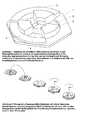
- Figure 1shows the oblique view of an implant according to the invention before assembly with its identical counterpart rotated by 180 °
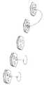
- Figure 2shows the assembly of the implant according to the invention with its identical implant partner to the overall implant in different implant height settings.
- Figure 1shows the spinal implant. It consists of the Implant body (1) which is in contact with the bone of the adjacent Vertebral body. Connected to this are guide elements (2), which in the corresponding guide grooves (3) of the identical Interact with the implant partner (1) and perform a telescopic movement enable. The guide grooves end in matching openings in the Implant body (3). When fully retracted, they close Guide elements with the base plate of the implant body. An inner (4) and an outer ring (5) with spacers arranged in a step-like manner defines the height of the total implant. The entire implant consists of two identical implants, another implant (1) is opposed placed. By gradually turning the two implant partners different heights can be achieved during assembly. Form elements on the top and bottom secure the implant against Displacement when implanted.
- An implant with threeis shown Heights.
- the number of adjustment optionsdefines the number of Guide elements and the number of spacers on the inner (4) and outer (5) height definition ring.
- the outer shape of the implantis also of this type dependent, in the present example there are three adjustment options with three guide elements (2) and three spacers each at 0 °, 120 ° and 240 ° on the height determination rings (4,5) a hexagonal outer shape.
- the double height adjustmentwould turn in 180 ° two guide elements, two guide grooves, two spacers and one square base, the 4-fold adjustment requires 4 elements each Type and an octahedron as the basic form.
- the theoretically possible simple one round basic shapeis avoided because it protrudes beyond the vertebral trailing edge.
- a hole (6) in the outer circumferenceis used to receive a Implant placement instrument when inserting the implant.
Landscapes
- Health & Medical Sciences (AREA)
- Engineering & Computer Science (AREA)
- Biomedical Technology (AREA)
- Orthopedic Medicine & Surgery (AREA)
- Neurology (AREA)
- Heart & Thoracic Surgery (AREA)
- Oral & Maxillofacial Surgery (AREA)
- Transplantation (AREA)
- Cardiology (AREA)
- Vascular Medicine (AREA)
- Life Sciences & Earth Sciences (AREA)
- Animal Behavior & Ethology (AREA)
- General Health & Medical Sciences (AREA)
- Public Health (AREA)
- Veterinary Medicine (AREA)
- Prostheses (AREA)
Abstract
Description
Translated fromGermanDie Erfindung bezieht sich auf Implantate, welche in der Wirbelsäulenchirurgienach der Entfernung von Zwischenwirbelscheiben (Bandscheiben) oderWirbelkörpern bzw. Teilen von Wirbelkörpern zur Wiederherstellung derStabilität der Wirbelsäule eingesetzt werden.The invention relates to implants used in spinal surgeryafter the removal of intervertebral discs (intervertebral discs) orVertebral bodies or parts of vertebral bodies to restore theSpine stability can be used.
Implantate kommen in der Wirbelsäulenchirurgie in vielfältiger Weise zumEinsatz. Da der größere Anteil der axialen Belastung der Wirbelsäule durch dievorderen Elemente also die Wirbelkörper getragen wird, kommen Implantatenzum Ersatz dieser tragenden Funktion eine besondere Bedeutung zu. Bei deroperativen Behandlung verschiedener Wirbelsäulenerkrankungen kommensolche Implantate zum Einsatz: so z.B. nach der Entfernung vonHalsbandscheiben wegen eines Bandscheibenvorfalles, nach der Entfernungvon Wirbelkörpern wegen einer angeborenen oder erworbenen Enge desdahinter liegenden Wirbelkanals oder wegen eines tumorösen Befalls einesWirbelkörpers. Mittels Implantat kann dann Statik und Funktion derWirbelsäule wiederhergestellt werden. Da genaue Größe nicht vor sondern erstbeim eigentlichen operativen Eingriff vom behandelnden Chirurgeneingeschätzt werden kann, ist im Normalfall eine größere Anzahl verschiedengroßer Implantate steril im Vorrat zu lagern.Implants are used in a variety of ways in spinal surgeryCommitment. Because the greater part of the axial load on the spine is caused by thefront elements so the vertebral body is worn, implants cometo replace this main function. In thesurgical treatment of various spinal disorders comesuch implants for use: e.g. after removal ofCollar discs due to a herniated disc after removalof vertebral bodies because of a congenital or acquired constriction of thevertebral canal behind it or because of a tumorous infectionVertebral body. The statics and function of theSpine to be restored. Because the exact size is not before but onlyduring the actual surgical intervention by the treating surgeoncan be estimated, a larger number is usually differentto store large implants in sterile stores.
Gegenstand der vorliegenden Erfindung ist ein in seiner Einbauhöhe variablesImplantat. Implantate mit variabler Höhe bzw. der Höhengewinn durch dasStapeln von Implantaten sind bekannt. Sie erfordern jedoch entwederkomplizierte Mechanismen zur Höheneinstellung oder zusätzliche Elemente(Schrauben oder Platten) zur mechanischen Stabilisierung derGesamtkonstruktion. Eine der wesentlichen Forderungen bei der Entwicklungmedizinischer Implantate ist ihre Robustheit gegenüber Störfaktoren und die(lebens-)langen Standzeiten bei vorher nicht abzuschätzender repetitiverBelastung.The present invention relates to a variable in its installation heightImplant. Implants with variable height or the height gain through theStacking implants are known. However, they require eithercomplicated mechanisms for height adjustment or additional elements(Screws or plates) for mechanical stabilization of theOverall design. One of the main requirements in the developmentmedical implants is their robustness against confounding factors and the(Lifetime) long service life with repetitive that cannot be estimated beforehandBurden.
Gegenstand der Erfindung ist in seiner Bauhöhe variables Implantat, welchesohne zusätzliche Elemente auskommt. Es besteht aus zwei identischen Teilen und erlaubt beim Zusammenbau der Komponenten abhängig von der axialenWinkelstellung zueinander einen Höhengewinn von 50% der Implantathöhe inmehreren Stufen.The object of the invention is variable in height, whichworks without additional elements. It consists of two identical partsand allows when assembling the components depending on the axialAngular position to each other a height gain of 50% of the implant height inseveral levels.
Das erfindungsgemäße Implantat weist mehrere Vorteile auf. Es liegt einstabiles Implantat vor, welches ohne vorherige Paß- und Probeimplatateeingesetzt werden kann. Bei zu geringer Vorspannung kann das gleicheImplantat in anderer Stellung montiert erneut eingesetzt werden. ZusätzlicheElemente zur Befestigung sind nicht notwendig. Das Risiko von Bruch,Lockerung oder Verlust dieser Elemente mit der Konsequenz einerNachoperation des Patienten werden vermieden.
Die Konstruktion ist einfach. Im Zusammenhang mit neuenKrankheitsübertragungswegen durch Prionenerkrankungen (BSE, neueVariante der Kreutzfeld-Jakob-Erkrankung) werden höhere Anforderungen anReinigung und Sterilisierbarkeit gestellt, so muß die weitestgehendeDemontierbarkeit zur Reinigung möglich sein. Komplizierte Implantate mitbeweglichen Teilen sind nach gegenwärtig üblicher Sterilisationsbehandlungnoch proteinkontaminiert und stellen ein potentielles Übertragungsrisiko dar.Nichtzuletzt ist das erfindungsgemäße Implantat universell. Der überwiegendeTeil der vorderen Halsbandscheibenchirurgie noterndigen Implantatbauhöhenwird sich mit einem einzelnen Typ Implantat abdecken lassen.The implant according to the invention has several advantages. There is a stable implant that can be used without previous fitting and trial implants. If the preload is too low, the same implant can be reinserted in a different position. Additional elements for fastening are not necessary. The risk of breakage, loosening or loss of these elements, with the consequence of a subsequent operation of the patient is avoided.
The construction is simple. In connection with new disease transmission pathways due to prion diseases (BSE, new variant of the Kreutzfeld-Jakob disease), higher requirements are placed on cleaning and sterilizability, so that it must be possible to remove them for cleaning as far as possible. Complicated implants with moving parts are still contaminated with protein after the current sterilization treatment and represent a potential risk of transmission. Not least, the implant according to the invention is universal. The majority of the frontal collar disc surgery required implant heights can be covered with a single type of implant.
Im folgenden wird die Erfindung anhand eines Beispiels und mit Bezug auf diebeiliegenden Zeichnungen näher erläutert, wobei
Abbildung 1 die Schrägansicht eines erfindungsgemäßen Implantates vor demZusammenbau mit seinem um 180° gedrehten identischen Gegenpart
und
Abbildung 2 die Montage des erfindunggemäßen Implantates mit seinemidentischen Implantatpartner zum Gesamtimplantat in verschiedenenImplantathöheneinstellungen zeigt.In the following the invention is explained in more detail using an example and with reference to the accompanying drawings, wherein
Figure 1 shows the oblique view of an implant according to the invention before assembly with its identical counterpart rotated by 180 °
and
Figure 2 shows the assembly of the implant according to the invention with its identical implant partner to the overall implant in different implant height settings.
In Abbildung 1 ist das Wirbelsäulen- Implantat dargestellt. Es besteht aus demImplantatkörper (1) welcher den Kontakt mit dem Knochen des angrenzendenWirbelkörpers aufnimmt. Verbunden damit sind Führungsselemente (2),welche in die entsprechenden Fuhrungsnuten (3) des identischenImplantatpartners (1) eingreifen und eine teleskopierende Bewegungermöglichen. Die Führungsnuten enden in passenden Öffnungen desImplantatkörpers (3). In voll eingefahreren Zustand schließen dieFührungselemente mit der Grundplatte des Implantatkörpers ab. Ein innerer(4)und ein äußerer Ring(5) mit treppenförmig angeordneten Abstandshalterndefiniert die Höhe des Gesamtimplantates. Das Gesamtimplantat besteht auszwei identischen Implantaten, ein weiteres Implantat (1) wird entgegengesetztaufgesetzt. Durch das graduelle Verdrehen der beiden Implantatpartner vordem Zusammenbau können verschiedene Bauhöhen erreicht werden.Formelemente auf Ober- bzw. Unterseite sichern das Implantat gegenVerschiebung im implantierten Zustand. Dargestellt ist ein Implantat mit dreiBauhöhen. Die Anzahl der Verstellmöglichkeiten definiert die Anzahl derFührungselemente und die Anzahl der Abstandshalter auf dem inneren (4) undäußeren (5) Höhendefinitionsring. Auch die äußere Implantatform ist davonabhängig, im vorliegenden Beispiel ergibt sich bei drei Verstellmöglichkeitenmit drei Führungselementen (2) und jeweils drei Abstandshaltern bei 0°, 120°und 240° auf den Höhendifinitionsringen (4,5) eine sechseckige Außenform.Analog dazu würde die 2-fache Höhenverstellung in jeweils 180° Drehungzwei Führungselemente, zwei Führungsnuten, zwei Abstandshalter und einequadratische Grundfläche bedingen, die 4-fache Verstellung 4 Elemente jedenTyps und einen Oktaeder als Grundform. Die theroretisch mögliche einfacherunde Grundform wird vermieden, da sie die Wirbelkörperhinterkante überragt.Eine Bohrung (6) in der äußeren Zirkumferenz dient zur Aufnahme einesImplantatsetzinstrumentes beim Einbringen des Implantates.Figure 1 shows the spinal implant. It consists of theImplant body (1) which is in contact with the bone of the adjacentVertebral body. Connected to this are guide elements (2),which in the corresponding guide grooves (3) of the identicalInteract with the implant partner (1) and perform a telescopic movementenable. The guide grooves end in matching openings in theImplant body (3). When fully retracted, they closeGuide elements with the base plate of the implant body. An inner (4)and an outer ring (5) with spacers arranged in a step-like mannerdefines the height of the total implant. The entire implant consists oftwo identical implants, another implant (1) is opposedplaced. By gradually turning the two implant partnersdifferent heights can be achieved during assembly.Form elements on the top and bottom secure the implant againstDisplacement when implanted. An implant with three is shownHeights. The number of adjustment options defines the number ofGuide elements and the number of spacers on the inner (4) andouter (5) height definition ring. The outer shape of the implant is also of this typedependent, in the present example there are three adjustment optionswith three guide elements (2) and three spacers each at 0 °, 120 °and 240 ° on the height determination rings (4,5) a hexagonal outer shape.Analogously, the double height adjustment would turn in 180 °two guide elements, two guide grooves, two spacers and onesquare base, the 4-fold adjustment requires 4 elements eachType and an octahedron as the basic form. The theoretically possible simple oneround basic shape is avoided because it protrudes beyond the vertebral trailing edge.A hole (6) in the outer circumference is used to receive aImplant placement instrument when inserting the implant.
Claims (2)
Translated fromGermanPriority Applications (3)
| Application Number | Priority Date | Filing Date | Title |
|---|---|---|---|
| AT01120459TATE318558T1 (en) | 2001-08-28 | 2001-08-28 | SPINE IMPLANT WITH ADJUSTABLE HEIGHT |
| EP01120459AEP1293180B1 (en) | 2001-08-28 | 2001-08-28 | Spinal implant with adjustable height |
| DE50109043TDE50109043D1 (en) | 2001-08-28 | 2001-08-28 | Spine implant with adjustable height |
Applications Claiming Priority (1)
| Application Number | Priority Date | Filing Date | Title |
|---|---|---|---|
| EP01120459AEP1293180B1 (en) | 2001-08-28 | 2001-08-28 | Spinal implant with adjustable height |
Publications (2)
| Publication Number | Publication Date |
|---|---|
| EP1293180A1true EP1293180A1 (en) | 2003-03-19 |
| EP1293180B1 EP1293180B1 (en) | 2006-03-01 |
Family
ID=8178427
Family Applications (1)
| Application Number | Title | Priority Date | Filing Date |
|---|---|---|---|
| EP01120459AExpired - LifetimeEP1293180B1 (en) | 2001-08-28 | 2001-08-28 | Spinal implant with adjustable height |
Country Status (3)
| Country | Link |
|---|---|
| EP (1) | EP1293180B1 (en) |
| AT (1) | ATE318558T1 (en) |
| DE (1) | DE50109043D1 (en) |
Cited By (8)
| Publication number | Priority date | Publication date | Assignee | Title |
|---|---|---|---|---|
| DE10357960A1 (en)* | 2003-12-09 | 2005-07-14 | Biedermann Motech Gmbh | Intervertebral implant for stabilizing two spaced vertebrae, comprises two parts, each having two ends, contact surface provided between two ends, and guide surface, where first guide surface extends out from first contact surface |
| US7618458B2 (en) | 2003-12-09 | 2009-11-17 | Biedermann Motech Gmbh | Height-adjustable intervertebrae implant |
| EP2299940A4 (en)* | 2008-07-02 | 2013-09-11 | Spinalmotion Inc | BELT PROPERTIES WITH RESTRICTED MOTION |
| EP2674133A1 (en)* | 2012-06-14 | 2013-12-18 | WALDEMAR LINK GmbH & Co. KG | Intervertebral fusion implant |
| US9320610B2 (en) | 2011-08-16 | 2016-04-26 | Stryker European Holdings I, Llc | Expandable implant |
| US9782271B2 (en) | 2008-02-28 | 2017-10-10 | Stryker European Holdings I, Llc | Expandable intervertebral implant |
| US10342675B2 (en) | 2013-03-11 | 2019-07-09 | Stryker European Holdings I, Llc | Expandable implant |
| CN114830939A (en)* | 2022-04-07 | 2022-08-02 | 安徽水利生态环境建设有限公司 | Emergent aquatic plant planting utensil made of degradable material |
Families Citing this family (1)
| Publication number | Priority date | Publication date | Assignee | Title |
|---|---|---|---|---|
| EP1610740A4 (en) | 2003-04-04 | 2009-04-08 | Theken Disc Llc | Artificial disc prosthesis |
Citations (3)
| Publication number | Priority date | Publication date | Assignee | Title |
|---|---|---|---|---|
| US5865848A (en)* | 1997-09-12 | 1999-02-02 | Artifex, Ltd. | Dynamic intervertebral spacer and method of use |
| US6159211A (en)* | 1998-10-22 | 2000-12-12 | Depuy Acromed, Inc. | Stackable cage system for corpectomy/vertebrectomy |
| WO2002009626A1 (en)* | 1999-07-26 | 2002-02-07 | Advanced Prosthetic Technologies, Inc. | Improved spinal surgical prosthesis |
- 2001
- 2001-08-28EPEP01120459Apatent/EP1293180B1/ennot_activeExpired - Lifetime
- 2001-08-28ATAT01120459Tpatent/ATE318558T1/ennot_activeIP Right Cessation
- 2001-08-28DEDE50109043Tpatent/DE50109043D1/ennot_activeExpired - Fee Related
Patent Citations (3)
| Publication number | Priority date | Publication date | Assignee | Title |
|---|---|---|---|---|
| US5865848A (en)* | 1997-09-12 | 1999-02-02 | Artifex, Ltd. | Dynamic intervertebral spacer and method of use |
| US6159211A (en)* | 1998-10-22 | 2000-12-12 | Depuy Acromed, Inc. | Stackable cage system for corpectomy/vertebrectomy |
| WO2002009626A1 (en)* | 1999-07-26 | 2002-02-07 | Advanced Prosthetic Technologies, Inc. | Improved spinal surgical prosthesis |
Cited By (16)
| Publication number | Priority date | Publication date | Assignee | Title |
|---|---|---|---|---|
| US7618458B2 (en) | 2003-12-09 | 2009-11-17 | Biedermann Motech Gmbh | Height-adjustable intervertebrae implant |
| DE10357960B4 (en)* | 2003-12-09 | 2015-09-03 | Biedermann Technologies Gmbh & Co. Kg | Height-adjustable intervertebral implant |
| DE10357960A1 (en)* | 2003-12-09 | 2005-07-14 | Biedermann Motech Gmbh | Intervertebral implant for stabilizing two spaced vertebrae, comprises two parts, each having two ends, contact surface provided between two ends, and guide surface, where first guide surface extends out from first contact surface |
| US9782271B2 (en) | 2008-02-28 | 2017-10-10 | Stryker European Holdings I, Llc | Expandable intervertebral implant |
| EP2299940A4 (en)* | 2008-07-02 | 2013-09-11 | Spinalmotion Inc | BELT PROPERTIES WITH RESTRICTED MOTION |
| US9220603B2 (en) | 2008-07-02 | 2015-12-29 | Simplify Medical, Inc. | Limited motion prosthetic intervertebral disc |
| US9962270B2 (en) | 2011-08-16 | 2018-05-08 | Stryker European Holdings I, Llc | Expandable implant |
| US11648131B2 (en) | 2011-08-16 | 2023-05-16 | Stryker European Operations Holdings Llc | Expandable implant |
| US10898344B2 (en) | 2011-08-16 | 2021-01-26 | Stryker European Operations Holdings Llc | Expandable implant |
| US9320610B2 (en) | 2011-08-16 | 2016-04-26 | Stryker European Holdings I, Llc | Expandable implant |
| US9333089B2 (en) | 2012-06-14 | 2016-05-10 | Waldemar Link Gmbh & Co., Kg | Intervertebral fusion implant |
| RU2633474C2 (en)* | 2012-06-14 | 2017-10-12 | ВАЛЬДЕМАР ЛИНК ГМБХ энд КО. КГ | Intervertebral connective implant |
| WO2013186112A1 (en)* | 2012-06-14 | 2013-12-19 | Waldemar Link Gmbh & Co. Kg | Intervertebral fusion implant |
| EP2674133A1 (en)* | 2012-06-14 | 2013-12-18 | WALDEMAR LINK GmbH & Co. KG | Intervertebral fusion implant |
| US10342675B2 (en) | 2013-03-11 | 2019-07-09 | Stryker European Holdings I, Llc | Expandable implant |
| CN114830939A (en)* | 2022-04-07 | 2022-08-02 | 安徽水利生态环境建设有限公司 | Emergent aquatic plant planting utensil made of degradable material |
Also Published As
| Publication number | Publication date |
|---|---|
| EP1293180B1 (en) | 2006-03-01 |
| ATE318558T1 (en) | 2006-03-15 |
| DE50109043D1 (en) | 2006-04-27 |
Similar Documents
| Publication | Publication Date | Title |
|---|---|---|
| DE69936263T2 (en) | SCREWED CYLINDRICAL, MULTIDISKOIDE EASY OR MULTIPLE NETWORK PLATE PROTESTS | |
| EP1729690B1 (en) | Modular intervertebral implant or intervertebral disc prosthesis | |
| EP2853242B1 (en) | Modular articulated spacer system | |
| EP2994074B1 (en) | Spinal implant | |
| DE69730509T2 (en) | DEVICE AND METHOD FOR INSERTING AN IMPLANT | |
| EP1959871B1 (en) | Facet joint prosthesis | |
| DE69837998T2 (en) | SWIVELING FUSION DEVICE WITH A PARTICULARLY CIRCULAR SECTION SHAPING CROSS SECTION SEGMENTS | |
| DE60019643T2 (en) | IMPLANT FROM BONE MATERIAL | |
| DE69534978T2 (en) | Adjustable vertebral body replacement | |
| EP1620023B1 (en) | Dynamic anchoring device and dynamic stabilizing device, which serves to stabilize bones, particularly vertebrae, and which has an anchoring device of this type | |
| EP0079441B1 (en) | Endoprosthesis for replacement of rod-shaped bones | |
| DE102004021861A1 (en) | Implant for temporary or permanent replacement of vertebra or intervertebral disk, comprising solid central element and outer elements with openings | |
| EP1572039A1 (en) | Intervertebral implant | |
| EP1534193A1 (en) | Intervertebral implant comprising a three-part articulation | |
| DE29913200U1 (en) | Bone material implant | |
| DE102009014184A1 (en) | Implant for fusion of spinal segments | |
| EP1121075A1 (en) | Telescopic vertebral prosthesis | |
| EP0857043A1 (en) | Inter-vertebral implant | |
| EP1293180A1 (en) | Spinal implant with adjustable height | |
| DE10061975C2 (en) | Intervertebral disc replacement implant part | |
| DE102009054633A1 (en) | Insertion tool for inserting socket inserts into the calipers of acetabular cups | |
| DE102012203256A1 (en) | Implant structure for supporting spine in inter vertebral space, has anterior support element and posterior support element that are connected with adjusting mechanism where support elements are spaced apart at a distance | |
| WO1996037169A1 (en) | Endoprosthesis for a metatarso-phalangeal joint | |
| DE102007042946A1 (en) | Implantable, prosthetic vertebral body replacement | |
| DE10158559C2 (en) | Femoral neck endoprosthesis for an artificial hip joint |
Legal Events
| Date | Code | Title | Description |
|---|---|---|---|
| PUAI | Public reference made under article 153(3) epc to a published international application that has entered the european phase | Free format text:ORIGINAL CODE: 0009012 | |
| AK | Designated contracting states | Kind code of ref document:A1 Designated state(s):AT BE CH CY DE DK ES FI FR GB GR IE IT LI LU MC NL PT SE TR | |
| AX | Request for extension of the european patent | Extension state:AL LT LV MK RO SI | |
| 17P | Request for examination filed | Effective date:20030820 | |
| AKX | Designation fees paid | Designated state(s):AT BE CH CY DE DK ES FI FR GB GR IE IT LI LU MC NL PT SE TR | |
| 17Q | First examination report despatched | Effective date:20050318 | |
| GRAP | Despatch of communication of intention to grant a patent | Free format text:ORIGINAL CODE: EPIDOSNIGR1 | |
| GRAC | Information related to communication of intention to grant a patent modified | Free format text:ORIGINAL CODE: EPIDOSCIGR1 | |
| GRAS | Grant fee paid | Free format text:ORIGINAL CODE: EPIDOSNIGR3 | |
| GRAA | (expected) grant | Free format text:ORIGINAL CODE: 0009210 | |
| AK | Designated contracting states | Kind code of ref document:B1 Designated state(s):AT BE CH CY DE DK ES FI FR GB GR IE IT LI LU MC NL PT SE TR | |
| PG25 | Lapsed in a contracting state [announced via postgrant information from national office to epo] | Ref country code:IT Free format text:LAPSE BECAUSE OF FAILURE TO SUBMIT A TRANSLATION OF THE DESCRIPTION OR TO PAY THE FEE WITHIN THE PRESCRIBED TIME-LIMIT;WARNING: LAPSES OF ITALIAN PATENTS WITH EFFECTIVE DATE BEFORE 2007 MAY HAVE OCCURRED AT ANY TIME BEFORE 2007. THE CORRECT EFFECTIVE DATE MAY BE DIFFERENT FROM THE ONE RECORDED. Effective date:20060301 Ref country code:FI Free format text:LAPSE BECAUSE OF FAILURE TO SUBMIT A TRANSLATION OF THE DESCRIPTION OR TO PAY THE FEE WITHIN THE PRESCRIBED TIME-LIMIT Effective date:20060301 Ref country code:NL Free format text:LAPSE BECAUSE OF FAILURE TO SUBMIT A TRANSLATION OF THE DESCRIPTION OR TO PAY THE FEE WITHIN THE PRESCRIBED TIME-LIMIT Effective date:20060301 Ref country code:IE Free format text:LAPSE BECAUSE OF FAILURE TO SUBMIT A TRANSLATION OF THE DESCRIPTION OR TO PAY THE FEE WITHIN THE PRESCRIBED TIME-LIMIT Effective date:20060301 | |
| REG | Reference to a national code | Ref country code:GB Ref legal event code:FG4D Free format text:NOT ENGLISH | |
| REG | Reference to a national code | Ref country code:CH Ref legal event code:EP | |
| REG | Reference to a national code | Ref country code:IE Ref legal event code:FG4D Free format text:LANGUAGE OF EP DOCUMENT: GERMAN | |
| REF | Corresponds to: | Ref document number:50109043 Country of ref document:DE Date of ref document:20060427 Kind code of ref document:P | |
| PGFP | Annual fee paid to national office [announced via postgrant information from national office to epo] | Ref country code:DE Payment date:20060503 Year of fee payment:6 | |
| PG25 | Lapsed in a contracting state [announced via postgrant information from national office to epo] | Ref country code:SE Free format text:LAPSE BECAUSE OF FAILURE TO SUBMIT A TRANSLATION OF THE DESCRIPTION OR TO PAY THE FEE WITHIN THE PRESCRIBED TIME-LIMIT Effective date:20060601 Ref country code:DK Free format text:LAPSE BECAUSE OF FAILURE TO SUBMIT A TRANSLATION OF THE DESCRIPTION OR TO PAY THE FEE WITHIN THE PRESCRIBED TIME-LIMIT Effective date:20060601 | |
| PG25 | Lapsed in a contracting state [announced via postgrant information from national office to epo] | Ref country code:ES Free format text:LAPSE BECAUSE OF FAILURE TO SUBMIT A TRANSLATION OF THE DESCRIPTION OR TO PAY THE FEE WITHIN THE PRESCRIBED TIME-LIMIT Effective date:20060612 | |
| GBT | Gb: translation of ep patent filed (gb section 77(6)(a)/1977) | Effective date:20060605 | |
| PG25 | Lapsed in a contracting state [announced via postgrant information from national office to epo] | Ref country code:PT Free format text:LAPSE BECAUSE OF FAILURE TO SUBMIT A TRANSLATION OF THE DESCRIPTION OR TO PAY THE FEE WITHIN THE PRESCRIBED TIME-LIMIT Effective date:20060801 | |
| PG25 | Lapsed in a contracting state [announced via postgrant information from national office to epo] | Ref country code:CH Free format text:LAPSE BECAUSE OF NON-PAYMENT OF DUE FEES Effective date:20060831 Ref country code:LI Free format text:LAPSE BECAUSE OF NON-PAYMENT OF DUE FEES Effective date:20060831 Ref country code:BE Free format text:LAPSE BECAUSE OF NON-PAYMENT OF DUE FEES Effective date:20060831 Ref country code:MC Free format text:LAPSE BECAUSE OF NON-PAYMENT OF DUE FEES Effective date:20060831 | |
| NLV1 | Nl: lapsed or annulled due to failure to fulfill the requirements of art. 29p and 29m of the patents act | ||
| ET | Fr: translation filed | ||
| REG | Reference to a national code | Ref country code:IE Ref legal event code:FD4D | |
| PLBE | No opposition filed within time limit | Free format text:ORIGINAL CODE: 0009261 | |
| STAA | Information on the status of an ep patent application or granted ep patent | Free format text:STATUS: NO OPPOSITION FILED WITHIN TIME LIMIT | |
| 26N | No opposition filed | Effective date:20061204 | |
| REG | Reference to a national code | Ref country code:CH Ref legal event code:PL | |
| PG25 | Lapsed in a contracting state [announced via postgrant information from national office to epo] | Ref country code:AT Free format text:LAPSE BECAUSE OF NON-PAYMENT OF DUE FEES Effective date:20060828 | |
| BERE | Be: lapsed | Owner name:SCHRODER, JOHANNES Effective date:20060831 | |
| PGFP | Annual fee paid to national office [announced via postgrant information from national office to epo] | Ref country code:GB Payment date:20070828 Year of fee payment:7 | |
| PG25 | Lapsed in a contracting state [announced via postgrant information from national office to epo] | Ref country code:GR Free format text:LAPSE BECAUSE OF FAILURE TO SUBMIT A TRANSLATION OF THE DESCRIPTION OR TO PAY THE FEE WITHIN THE PRESCRIBED TIME-LIMIT Effective date:20060602 | |
| PGFP | Annual fee paid to national office [announced via postgrant information from national office to epo] | Ref country code:FR Payment date:20070821 Year of fee payment:7 | |
| PG25 | Lapsed in a contracting state [announced via postgrant information from national office to epo] | Ref country code:TR Free format text:LAPSE BECAUSE OF FAILURE TO SUBMIT A TRANSLATION OF THE DESCRIPTION OR TO PAY THE FEE WITHIN THE PRESCRIBED TIME-LIMIT Effective date:20060301 Ref country code:LU Free format text:LAPSE BECAUSE OF NON-PAYMENT OF DUE FEES Effective date:20060828 Ref country code:DE Free format text:LAPSE BECAUSE OF NON-PAYMENT OF DUE FEES Effective date:20080301 | |
| PG25 | Lapsed in a contracting state [announced via postgrant information from national office to epo] | Ref country code:CY Free format text:LAPSE BECAUSE OF FAILURE TO SUBMIT A TRANSLATION OF THE DESCRIPTION OR TO PAY THE FEE WITHIN THE PRESCRIBED TIME-LIMIT Effective date:20060301 | |
| GBPC | Gb: european patent ceased through non-payment of renewal fee | Effective date:20080828 | |
| REG | Reference to a national code | Ref country code:FR Ref legal event code:ST Effective date:20090430 | |
| PG25 | Lapsed in a contracting state [announced via postgrant information from national office to epo] | Ref country code:FR Free format text:LAPSE BECAUSE OF NON-PAYMENT OF DUE FEES Effective date:20080901 | |
| PG25 | Lapsed in a contracting state [announced via postgrant information from national office to epo] | Ref country code:GB Free format text:LAPSE BECAUSE OF NON-PAYMENT OF DUE FEES Effective date:20080828 |