EP1290658B1 - Wireless system protocol for telemetry monitoring - Google Patents
Wireless system protocol for telemetry monitoringDownload PDFInfo
- Publication number
- EP1290658B1 EP1290658B1EP01930556AEP01930556AEP1290658B1EP 1290658 B1EP1290658 B1EP 1290658B1EP 01930556 AEP01930556 AEP 01930556AEP 01930556 AEP01930556 AEP 01930556AEP 1290658 B1EP1290658 B1EP 1290658B1
- Authority
- EP
- European Patent Office
- Prior art keywords
- base unit
- wireless
- transceiver
- commands
- command
- Prior art date
- Legal status (The legal status is an assumption and is not a legal conclusion. Google has not performed a legal analysis and makes no representation as to the accuracy of the status listed.)
- Expired - Lifetime
Links
Images


Classifications
- A—HUMAN NECESSITIES
- A61—MEDICAL OR VETERINARY SCIENCE; HYGIENE
- A61B—DIAGNOSIS; SURGERY; IDENTIFICATION
- A61B5/00—Measuring for diagnostic purposes; Identification of persons
- A61B5/0002—Remote monitoring of patients using telemetry, e.g. transmission of vital signals via a communication network
- A61B5/0004—Remote monitoring of patients using telemetry, e.g. transmission of vital signals via a communication network characterised by the type of physiological signal transmitted
- A61B5/0006—ECG or EEG signals
- A—HUMAN NECESSITIES
- A61—MEDICAL OR VETERINARY SCIENCE; HYGIENE
- A61B—DIAGNOSIS; SURGERY; IDENTIFICATION
- A61B5/00—Measuring for diagnostic purposes; Identification of persons
- A61B5/06—Devices, other than using radiation, for detecting or locating foreign bodies ; Determining position of diagnostic devices within or on the body of the patient
- A61B5/061—Determining position of a probe within the body employing means separate from the probe, e.g. sensing internal probe position employing impedance electrodes on the surface of the body
- A—HUMAN NECESSITIES
- A61—MEDICAL OR VETERINARY SCIENCE; HYGIENE
- A61B—DIAGNOSIS; SURGERY; IDENTIFICATION
- A61B2560/00—Constructional details of operational features of apparatus; Accessories for medical measuring apparatus
- A61B2560/02—Operational features
- A61B2560/0204—Operational features of power management
- A61B2560/0209—Operational features of power management adapted for power saving
- A—HUMAN NECESSITIES
- A61—MEDICAL OR VETERINARY SCIENCE; HYGIENE
- A61B—DIAGNOSIS; SURGERY; IDENTIFICATION
- A61B2560/00—Constructional details of operational features of apparatus; Accessories for medical measuring apparatus
- A61B2560/04—Constructional details of apparatus
- A61B2560/0406—Constructional details of apparatus specially shaped apparatus housings
- A61B2560/0412—Low-profile patch shaped housings
- A—HUMAN NECESSITIES
- A61—MEDICAL OR VETERINARY SCIENCE; HYGIENE
- A61B—DIAGNOSIS; SURGERY; IDENTIFICATION
- A61B5/00—Measuring for diagnostic purposes; Identification of persons
- A61B5/24—Detecting, measuring or recording bioelectric or biomagnetic signals of the body or parts thereof
- A61B5/316—Modalities, i.e. specific diagnostic methods
- A61B5/369—Electroencephalography [EEG]
- A—HUMAN NECESSITIES
- A61—MEDICAL OR VETERINARY SCIENCE; HYGIENE
- A61B—DIAGNOSIS; SURGERY; IDENTIFICATION
- A61B5/00—Measuring for diagnostic purposes; Identification of persons
- A61B5/24—Detecting, measuring or recording bioelectric or biomagnetic signals of the body or parts thereof
- A61B5/316—Modalities, i.e. specific diagnostic methods
- A61B5/389—Electromyography [EMG]
- Y—GENERAL TAGGING OF NEW TECHNOLOGICAL DEVELOPMENTS; GENERAL TAGGING OF CROSS-SECTIONAL TECHNOLOGIES SPANNING OVER SEVERAL SECTIONS OF THE IPC; TECHNICAL SUBJECTS COVERED BY FORMER USPC CROSS-REFERENCE ART COLLECTIONS [XRACs] AND DIGESTS
- Y10—TECHNICAL SUBJECTS COVERED BY FORMER USPC
- Y10S—TECHNICAL SUBJECTS COVERED BY FORMER USPC CROSS-REFERENCE ART COLLECTIONS [XRACs] AND DIGESTS
- Y10S128/00—Surgery
- Y10S128/903—Radio telemetry
Definitions
- This inventionrelates generally to the field of devices used to measure electrical bio-potential signals generated by a human body, such as electrocardiogram (ECG), electroencephalogram (EEG) and electromyography (EMG) signals. More particularly, the invention relates to a wireless signal acquisition system and over the air communications protocol that is used between a plurality of wireless, remotely programmable transceivers, each coupled to a conventional patch electrode, and an associated base unit.
- the base unitobtains a patient's ECG, EEG or EMG signal from the wireless transceivers and supplies the signal to monitor unit for display.
- the wireless communications protocolallows the base unit to remotely configure and manage the wireless transceivers, prior to and during data acquisition and transmission.
- ECG monitoringtypically requires direct wired electrical connections between electrodes that are attached to the body of the patient at one end and to an ECG monitor on the other end. Electric bio-potentials are measured at the electrodes and signals are transformed via bipolar and unipolar leads into an electrocardiogram.
- ECG apparatusfor hospital bedside monitoring typically requires up to ten wired electrodes. Each electrode is attached to the body of the patient, and has a wire, several feet or more in length, leading to an ECG monitor.
- the lengthy wired electrodes of conventional ECG apparatusobstruct the patient and limit the patient's freedom of movement. They are also cumbersome for the physician or assisting nurse.
- U.S. Patent 5,862,803 to Besson et al .describes a wireless electrode/sensor patch system with sensor, controller and transceiver electronics contained in an electrode patch assembly.
- U.S. Patents 5,307,818 , 5,168,814 and 4,981,141all issued to Segalowitz, describe a wireless electrode system for ECG monitoring.
- the Besson et al. and Segalowitz patentsare incorporated by reference herein.
- the Segalowitz patentsdescribe a single piece electrode patch with built-in microchips for wireless one way communication, and a snap on electronic-assembly that fastens to a disposable electrode patch.
- the electrode patchis a special two-conductor type that is not conventional.
- the electrode assembliesare either transmit only or receive only (not both).
- a reference signal(generated from a Wilson network) is transmitted from the base unit to only the Right Leg electrode patch, which is receive only.
- Electrodescan only be programmed via manual switches on the electrode casing, not over-the-air from the base unit.
- the base unitcontains multiple receivers and antennas which imply multiple transmit frequencies are required for the system and over-the-air signaling (thus making the base unit more costly to implement). There is no mention of error correction or detection capability in the electrodes or base unit.
- This monitoring systemis also more immune to noise artifacts since the digitization process of the data occurs right at the electrode measurement point and not through extended wires.
- the protocol defined hereindescribes initialization, configuration, and management of the wireless electrode network. It also describes data acquisition and transfer to the base unit that synchronizes and coordinates electrode functions.
- the wireless systemhas a base unit and a plurality of wireless sensors for attachment to a patient's body.
- the inventionis defined in claims 1, 12 and 23.
- each of the wireless sensorshas a transceiver assembly for transmitting and receiving two-way wireless communications with a base unit.
- the transceiver assemblyincludes a computing platform (such as a microcontroller) and a memory storing a set of instructions for execution by the computing platform in response to commands received from the base unit.
- the base unitis provided with a wireless transceiver for transmitting and receiving wireless communications with the sensors.
- the wireless communicationsinclude, among other things, commands for the transceiver assemblies.
- a set of instructionsis provided in the base unit, such as in a memory for a base unit microcontroller, wherein the base unit issues the commands to the transceiver assemblies in response to the execution of the instructions.
- the commands from the base unit and the responses to those commands from the transceiver assembliescomprise a procedure or protocol by which the base unit may remotely, and automatically, manage and configure the transceiver assemblies during real time as the transceiver assemblies acquire and transmit physiologic signal data to the base unit.
- the wireless communications procedures described hereinare particularly well suited for use in a system acquiring EEG, ECG or EMG signals from a human patient.
- the programmable wireless transceiversare associated with a sensor in the form of a conventional patch electrode, and acquire bio-potential signals between conductors in the electrode.
- the patch electrodesare of conventional design and adapted to be placed on the surface of the patient's body for measuring electrical bio-potentials.
- the present inventiondescribes wireless programming procedures that allow flexibility in configuration of telemetry based electrode system to adapt to changing requirements of different applications.
- This inventionprovides for procedures that are not only specific to ECG, but can equivalently be applied in other application areas such as EEG, EMG, EOG, Respiratory, Tonometric Blood Pressure, Temperature and other wireless medical monitoring systems.
- the programming proceduresare dynamic, responsive to real time conditions as data is being acquired and transmitted to the base unit.
- the protocolprovides for transmission of a variety of configuration commands.
- commandsinclude registration information, data acquisition control commands (such as start and stop messages), transmission frequency commands, time slot commands, amplifier gain commands, transmitter control commands, power saving mode commands, initialization commands, and so forth.
- the base unit and the wireless transceiversmay use time division multiplexing as a communications format for transfer of the acquired signals to the base unit.
- the base unittransmits a global time base signal to the plurality of individual wireless transceivers.
- the global time base signalis used for synchronizing the timing of transmission of signals acquired by the individual wireless transceivers to the base unit in discrete time slots in a single frequency channel.
- This time division multiplexingprovides that each wireless transceiver transmits its signals to the base unit in discrete time slots, with the wireless transceivers sharing a common frequency channel.
- wireless transceiverand “programmable wireless transceiver” are meant to refer to the wireless electrode transceiver assembly as a unit, as distinguished from the actual transceiver module within the assembly, unless the context clearly indicates otherwise.
- electrodeis meant to be interpreted broadly to cover bio-sensors generally.
- the present inventioncan be used in a system consisting of multiple smart wireless transceiver devices sized to snap onto conventional disposable patch wireless sensors or electrodes for wireless patient monitoring, and a base unit communicating with the wireless transceivers that is also capable of interfacing to existing conventional bedside monitoring equipment, such as a standard ECG or EEG monitor.
- the wireless transceiversreceive commands from the base unit such as registration information, transmission frequency commands, amplifier gain commands, transmitter control commands, power saving mode, etc. and include hardware and software or firmware for processing these commands and responsively configuring the wireless transceiver accordingly. These commands are the result of execution of program instructions in a computing platform, such as a microcontroller, in the base unit and a set of response instructions in a computing platform in the wireless transceivers.
- a global time base signalis transmitted from the base unit to the electrodes to serve in synchronizing the timing of acquisition of sample points for all electrodes used in measuring input body surface potentials (e.g., ECG signal).
- the base unitreceives the transmitted ECG signal from each electrode (at predetermined time intervals if time division multiplexing is the embodiment of the communication protocol), demodulates, decodes (with error correction), digitally processes the data, applies any needed signal conditioning (amplification, filtering), and converts back to analog form for outputting the ECG signals to the standard ECG equipment for display.
- the base unitalso has a universal interface to existing standard ECG equipment so that the wireless link between the electrodes and base unit appears transparent to the ECG equipment. The ECG equipment will accept the individual electrode signals for developing any required lead configuration.
- the wireless transceivers and base unituse a unique over-the-air communication protocol between the base unit and the electrodes which allows wireless programming (configuration), identification, auditing, data acquisition control, and transmitter control of each electrode used in the system during real time.
- the systemcould be designed such that transmission of multi-channel signals is on a single digitally encoded frequency channel between the base unit transceiver and multiple electrode devices by using time division multiplexing.
- each electrodewill receive synchronization data from the base unit on the same receive frequency, and instruction on which time slot to transmit it's digitally encoded data. This makes it possible for multiple patients each on a separate frequency channel to use the wireless system in the same hospital room if there is limited bandwidth.
- a system 10according to a presently preferred embodiment is shown schematically for use with a patient 12.
- the system 10acquires ECG, EMG, EEG or other types of signals from the patient 12 and supplies them to a monitor 14.
- ECGECG
- EMGEEG
- monitor 14The present example will be discussed in terms of an ECG system, but the invention is directly applicable to other types of medical monitoring.
- the system 10is a wireless system, in that a plurality of electrode assemblies 16 receive commands (e.g., synchronization and control commands) from a base unit 18 using wireless transmission methods, and supply the ECG signals to the base unit 18 using wireless transmission methods as well.
- commandse.g., synchronization and control commands
- the electrode assemblies 16 of FIG. 1consist of a plurality of individual, remotely programmable wireless transceiver assemblies 20, each transceiver assembly designed to snap onto a conventional patch electrode 22 (such as the 3M Red dot electrode) used in ECG monitoring.
- the wireless transceivers 20are described in further detail in conjunction with Figure 2 and 3.
- the base unit 18includes a wireless transceiver for sending and receiving messages to the plurality of individual wireless transceivers, and is described in further detail in conjunction with Figures 4, 6, 8 and 9.
- the base unitfurther has an interface for providing analog ECG signals received from the wireless transceivers 20 to a conventional ECG display monitor 14.
- a preferred communications format for wireless communication between the base unit 18 and the wireless transceivers 20is time division multiplexing in a common frequency channel in the uplink direction, that is between the transceivers and the base unit.
- Each wireless transceiver 20transmits ECG signals in a particular time slot in the channel, as indicated in FIG. 5.
- the base unittransmits control commands and other information in a common channel that all the wireless transceivers are tuned to.
- the time slot assignment, frequency assignment, and other transmission control informationis managed and controlled by the base unit 18, as described in further detail below.
- An alternative embodimentis to use code division multiple access (CDMA) communication format for wireless communication between the base unit 18 and the wireless transceivers 20.
- CDMAcode division multiple access
- the messages transmitted by the base unit 18also include configuration commands for the wireless transceivers 20. These configuration commands can be, for example, change or set the data acquisition sampling rate, amplifier gain setting, and channel carrier settings, and can also consist of a timing signal for synchronization of the transmission time slot.
- the base unit 18transmits a global time base signal to all of the wireless transceivers.
- the global time base signalsynchronizes the timing of transmission of the ECG signals acquired by all of the wireless transceivers 20, such that the transmissions are in discrete time slots in a single frequency channel, as shown in FIG. 5.
- packets of dataare transmitted between the base unit and the wireless transceivers. Particular fields in the packets (bytes of data) are reserved for control data, payload data, CRC or error correction data, etc. in accordance with known wireless transmission protocols, conventional data transmission techniques such as IP or Ethernet, or similar techniques.
- a presently preferred protocol and message structureis described later in this document in conjunction with FIGs. 11-30.
- FIG. 2is a detailed perspective view of one of the patch electrodes 22 or sensors and associated remotely programmable wireless transceiver 20 assembly 16 of FIG. 1, it being understood that all of such patch electrodes and wireless transceivers of FIG. 1 are of a construction similar to that shown in FIG. 2.
- the patch electrode 22is adhered to the surface of the patient's body 12 in conventional fashion.
- the patch electrode 22includes a conductor 24 supplying ECG or other signals to a pin 26.
- the pin 26is received in complementary pin receiving structure 28 in the wireless transceiver 20 so as engage (as in a snap fit) the two parts 20 and 22.
- the pin receiving structure 28conducts electrical impulses with respect to a local ground reference to electronic circuitry in the wireless transceiver 20.
- the local ground referenceconsists of a flexible strip 21 connected to the transceiver 20 having a tip or skin contact 21A, made from a conductive material, which is placed underneath the patch electrode 22 in contact with the skin. The purpose is to allow the transceiver to measure the bio-potential difference between the signal contact point 26 and the local ground reference 21/21A.
- the material used for the strip 21could be a thin flexible material such as plastic with an internal conductive trace or lead wire from the transceiver 20 to the skin contact point 21A.
- the skin contact point 21Ais preferably coated with conductive silver chloride (AgCl) material 21B on one side thereof.
- FIG. 3is a block diagram of the wireless transceiver of FIG.s 1 and 2.
- the transceiver assembly 20snaps onto the post pin 26 of a disposable conventional patch electrode. Electrical signals provided from the electrode 22 are supplied to a low noise, variable gain amplifier 30 in the wireless transceiver 20.
- the amplifier 30may include a pre-amp stage.
- the analog signalis filtered, sampled and converted to digital signals in the A/D converter 32.
- the digital signalsare supplied to a computing platform, illustrated as a microcontroller/Digital Signal Processor 34.
- the microcontrollerperforms signal processing of the digital signal supplied by the A/D converter 32.
- the signal processing functionsinclude noise filtering and gain control of the digital ECG signal.
- gain control in the transceiver assemblycould be performed by adjustment of the amplifier 30 gain in the analog signal path.
- the microcontrolleralso processes commands and messages received from the base unit, and executes firmware instructions stored in a memory 36.
- the memoryfurther stores a unique electrode identifier as described in further detail below.
- the memorymay also store a position location identifier or data associated with a position the electrode is attached to the patient. The position location identifier or data is dynamically programmable from the base unit.
- the processed digital ECG signalsare buffered in a buffer 38, supplied to an encoder/decoder 40 and fed to a RF transceiver module 42 for transmission to the base unit via a low power built-in RF antenna 44.
- the transceiver 42includes a modulator/demodulator, transmitter, power amp, receiver, filters and an antenna switch.
- a frequency generator 46generates a carrier frequency for the RF transmission. The frequency is adjustable by the microcontroller 34.
- a battery 45 with a negative terminal connected to a local ground referenceprovides DC power to the components.
- the microcontroller/DSP 34controls the frequency generator 46 so as to select a frequency for wireless transmission of data and control messages to the base unit.
- the microcontroller in the computing platform 34also executes an initialization routine wherein the receiver scans a default receive channel for commands from the base unit, and if the commands are received the transmitter transmits identification information in an assigned frequency and time slot to the base unit.
- All or some of the individual blocks shown in FIG. 3could be combined in a microchip or microchips to miniaturize the size of the snap-on wireless transceiver assembly 20.
- the base unit 18transmits commands to all of the wireless transceivers and instructs each transceiver to transmit its ECG data individually (such as in time division multiplexing).
- the base unitreceives the transmitted ECG signals from the electrodes (up to 10) in sequence and then demodulates, decodes, error corrects, de-multiplexes, buffers, signal conditions, and reconverts each electrode's data back to an analog signal for interfacing to the standard ECG monitor 14.
- the base unitalso transmits programming information to the electrodes for frequency selection, power control, etc.
- the base unit 18includes a low power RF antenna 50, a frequency generator 52 for generating a carrier frequency and an RF transceiver 54.
- the transceiver 54includes a modulator/demodulator, transmitter, power amp, receiver, filters and an antenna switch.
- the base unitfurther includes a encoder/decoder 56, a computing platform such as a microcontroller/Digital Signal Processor (DSP) 58, and a memory 60 storing code for execution by the microcontroller/DSP, and I/O interface 59 for connection to a personal computer which is used as a test port for running system diagnostics, base unit software upgrades, etc., and a user interface 61.
- DSPDigital Signal Processor
- the user interface 61may consist of the following: a display for indicating electrode programming information or error/alarm conditions, a keypad or buttons for user requested inputs, an alarm unit for audibly indicating error/alarm conditions (for example a detached, low battery or failed electrode), and LEDs for visually indicating error, alarm or programming status.
- the time slot ECG data received from the wireless transceiversis demultiplexed in demultiplexer 62 and supplied to a buffer 64.
- a digital to analog filter bank 66converts the multiple channels of digital data from the wireless transceivers to analog form.
- the analog signalsare amplified by amplifiers 68 and supplied to an OEM (original equipment manufacturer) standard ECG monitor interface 70.
- the interface 70could be either part of the base unit 18 assembly so that it can directly plug into the ECG display equipment 14 via a standard connector, or it could be part of a cable connection to the display equipment.
- the idea with the OEM interface 70is to supply multiple analog ECG signals to the conventional ECG display equipment already used in the hospital environment, in a compatible and transparent manner, such that the display equipment would treat the signals as if they were generated from conventional wired electrodes. Familiarity with the analog signal acquisition hardware or electronics for the ECG display equipment 14 will be required obviously, and the OEM interface circuitry may vary depending on the manufacturer of the display equipment.
- the OEM monitor interface detailed designis considered within the ability of a person skilled in the art.
- a possible transmission scheme between the wireless transceivers 20 and the base unit 18is time division multiplexing. This allows a single transmit frequency to be used by all the electrodes in the ECG system. All electrodes receive commands and synchronization data (time base signal, reference signal and control data 76) from the base unit 18 on an assigned receive frequency (downlink) channel. The electrode receive channel may or may not be slotted (time multiplexed). Electrode 1 20/22A transmits it's data on time slot 1 72 (Electrode 2 20/22B on time slot 2 74, etc.) at the assigned transmit frequency (uplink) channel. The base unit 18 receives the transmission from the electrodes 20/22 and demultiplexes, buffers, and reconstructs the individual electrode data.
- the system 10 of FIG. 1utilizes an over the air programming mechanism to exchange messaging and information between the base unit 18 and the wireless transceivers 20.
- Various types of informationcould be exchanged.
- the base unit 18transmits a data acquisition control message to the wireless transceivers, which tells the microcontroller in the wireless transceivers to start and stop data acquisition.
- Another commandwould be a frequency selection command message(s) sent to the wireless transceivers, in which the wireless transceivers responsively select a common frequency channel for transmission of acquired ECG signals to the base unit in discrete time slots.
- the system 10 of FIG. 1provides a registration mechanism for every wireless transceiver and electrode assembly whereby an electrode identifier is programmed into the base unit, as well as the electrode functional position on the patient (i.e., LA, RA, LL, V1, V2, V3, V4, V5, or V6 in an ECG embodiment).
- An Electrode Serial Identifier(ESI) will encode the wireless transceiver's unique serial number.
- Each wireless transceiveris assigned an Electrode Temporary Identifier (ETI) after each registration scenario (on power up or reconfiguration).
- ETIElectrode Temporary Identifier
- the temporary identifiercan be composed of electrode number and random number for example.
- the ESIwill be included in each message or data transaction from each electrode to the base unit.
- the electrode identifierwill serve to ensure that only registered electrodes input signaling will be accepted by the associated base unit, in the event that two monitoring systems are transmitting on the same frequency channel, or in the case of interference detection.
- the systemwill provide a registration mechanism whereby a base unit identifier is programmed into the wireless transceiver assemblies being used.
- the Base Unit Serial Identifier(BUSI) will encode the base unit serial number.
- BUSIBase Unit Serial Identifier
- BUTIBase Unit Temporary Identifier
- the base unit identifierwill be included in each message or data transaction from the base unit to each wireless transceiver assembly.
- the base unit identifierwill serve to ensure that only the registered base unit input signaling (commands) will be accepted by the assemblies, in the event that two monitoring systems are transmitting on the same frequency channel, or in the case of interference detection.
- Figure 6shows a flow diagram of a possible initialization procedure (for both the base unit 18 and electrodes 20/22) for use where the transmission scheme between the base unit and the wireless transceivers 20 is time division multiplexing.
- This procedureassumes that each electrode in the ECG system contains a unique identifier and a unique functional position ID (i.e., LA, RA, LL, V1, V2, V3, V4, V5, or V6).
- the procedure of FIG. 6is reduced to a set of instructions stored in the base unit's memory 60 for execution by the microcontroller 58, as shown in FIG. 4, and in a set of response instructions stored in the wireless transceiver 22's memory and microcontroller of FIG. 3.
- the base unitis powered up.
- the base unitis configured for the number of leads used in the ECG system, such as 3, 5 or 12. The configuration could be facilitated by means of any suitable user interface on the base unit 18, such as a display and buttons as shown in FIG. 9 and described subsequently.
- the base unitscans its receive channels, a list of which is programmed into the base unit.
- the base unitdetermines whether any other ECG base unit transmissions are detected. If so, at step 86 the base unit selects the next unused frequency from the list of predetermined frequency channels as a transmit channel. If not, at step 88 the base unit selects the first frequency from the list of predetermined frequency channels as the transmission channel. The process then proceeds to step 90.
- the base unitstars transmitting electrode registration data and messages on the default programming channel determined in steps 86 or 88.
- the registration data and messagesinclude a base unit identification code or serial number. The registration data and messages were described earlier. This insures that the wireless transceivers to be associated with this particular base unit being initialized respond to commands from this base unit and no other base unit.
- the base unitinstructs all required electrodes to transmit on a predetermined frequency channel, and assigns time slots to each electrode. The base unit then communicates with electrodes to complete registration. If a particular electrode or electrodes did not complete registration, the base unit indicates via its user interface which electrode is not registered at step 96.
- the base unitsinstruct all electrodes to receive commands on a new predetermined frequency channel at step 98.
- the base unitinstructs all electrodes to begin ECG data acquisition and to transmit at the assigned frequency and in the assigned time slot.
- Step 100may be started in response to a user prompt via the base unit user interface.
- the base unitcontinuously monitors for interference on the receive data channel (uplink direction). If excessive interference occurs (such as from a high bit error rate detected in the base unit microcontroller), the base unit selects a new channel from the list of available frequencies for the electrodes to transmit on and commands a change in transmit frequency.
- FIG. 7is a flow diagram of an electrode initialization procedure that may be employed.
- the electrodesWhen the electrodes are initially powered up at step 110, the electrodes will be in a receive only mode.
- the electrodesautomatically scan the default receive channel to see if any commands and synchronization signals are being transmitted by the base unit. If no commands and synchronization commands are received at step 114, the electrode goes back to step 112 and selects another receive frequency from its list of default frequencies. If commands and synchronization data have been received, at step 116 the electrode sends is unique identification data (containing information on the position on the patient's body) on the assigned frequency and in the assigned time slot back to the base unit, indicating to the base unit that it is ready to acquire ECG signals and is in an operating condition.
- unique identification datacontaining information on the position on the patient's body
- the plurality of individual, remotely programmable wireless transceivers 20are initially generic with respect to particular placement locations on the surface of a patient's body.
- the electrodescould be manufactured without preprogrammed functional position identifiers. This is advantageous since it would not be necessary to have the hospital or user maintain an inventory of individual electrodes based on functional position (i.e., LA, RA, LL, V1, V2, etc.). All the electrode assemblies are considered generic and could be programmed with unique identifiers indicating the position on the body by the base unit when the user sets up the ECG system.
- the procedure of FIG. 8could be used for programming of each electrode when initializing the ECG system. After first time programming of the electrode assemblies, the system only needs to go through the initialization program of FIG. 6 when it is powered up again.
- FIG. 8shows the initialization procedure in the alternative embodiment.
- FIG. 9shows the base unit 18 having a user interface 61 comprising a display 132 and a plurality of buttons or keys 133 for assisting the user to interact with the base unit.
- a group of generic wireless transceivers 20are shown ready for initialization.
- the userhas a set of pre-printed labels 135, which are removed from a plastic backing and placed on the wireless transceivers as shown in FIG. 10.
- the usersets up the base unit into an electrode programming mode, such as by responding to prompts on the display 132 and selecting the mode with one of the buttons or keys 133.
- the base unit programming modecould be done at lower power transmissions, requiring the wireless transceiver 20 to be programmed to be adjacent to the base unit (thereby avoiding programming more than one transceiver at a time).
- the base unithas a programming initialization interface 136 which makes contact with a socket or other feature in the transceiver for purposes of programming the transceiver during initialization. When the transceiver is placed into contact with the programming initialization interface 136, the base unit could automatically go into programming mode, or it could simply go into programming mode upon power up.
- the first electrode assembly 20/22is powered up and placed near the base unit or positioned in contact with the programming initialization interface 136.
- the initialization of the electrodescould be done by mechanical means, such as plugging the electrode transceiver 20 into the base unit programming initialization interface 136.
- the electrodescans the default programming channel.
- the base unitsends a low power programming command on the default transmit channel or some other channel that has the least RF interference.
- the electrodedetermines whether it has received the programming command. If not, the electrode scans the list of default channels and selects a new channel to listen on. If so, the electrode transmits a response message on its assigned transmit channel at step 150.
- the base unitdetermines whether it has received the response from the electrode. If not, the base unit goes back to step 146 and transmits the low power programming command on a new transmit channel. If so, the base unit transmits programming data to the electrode at step 153.
- the programming dataincludes the electrode unique identifier, including the electrode position (LA, RL, or V3, etc.), the base unit unique identifier, and other registration commands as described above.
- the electrodedetermines whether a programming error was detected, and if so at step 156 sends a retransmit program message to base unit causing it to repeat the programming data at step 152. If no error occurred, the process proceeds to step 158, at which the electrode completes programming with the base unit.
- the base unitinstructs the electrode to wait for additional commands.
- the unique base unit IDsince the unique base unit ID has been programmed in the wireless transceiver, it can scan ECG system control channels and receive and operate on commands only from the base unit that programmed the transceiver.
- the base unitdisplays the electrode placement position on the user interface display and prompts the user to place the next electrode for programming into the initialization interface 136.
- the base unitwill automatically be configured for the proper number of electrodes used in the ECG system.
- the userremoves a label 135 from the stock of labels 137 indicating the position programmed on the electrode and applies the label to the electrode (e.g., to the top or upper surface of the wireless transceiver 20), as shown in FIG. 10.
- a dynamically programmable, wireless electrocardiograph (ECG) acquisition systemcomprising: a plurality of individual, remotely programmable wireless transceivers 20, each transceiver associated with a patch electrode 22 for use in ECG monitoring, and a base unit 18 comprising a wireless transceiver 54 (FIG. 4) for sending and receiving messages to the plurality of individual transceivers 20.
- the base unit and wireless transceivers 22implement a wireless programming protocol by which messages and information are exchanged between base unit 18 and wireless transceivers 20 (such as shown in FIG. 6 and 8) whereby registration, configuration, and data transmission control properties of the wireless transceivers may be managed by the base unit.
- the base unittransmits a global time base signal to the wireless transceivers, the global time base signal synchronizing the timing of transmission of ECG signals acquired by the wireless transceivers in discrete time slots in a single frequency channel.
- the base unitfurther comprises an interface 70 to a conventional ECG monitoring equipment such as a display, whereby acquired ECG signals may be transmitted to the ECG monitoring equipment for display.
- the system of base unit 18 and wireless remotely programmable transceivers 20is particularly well adapted for use with standard conventional patch electrodes and existing ECG monitoring equipment, and thus presents a flexible, low cost and convenient approach to acquiring ECG signals and presenting them to a display unit for display.
- the system 10 of FIG. 1utilizes over the air (OTA) programming procedures to exchange messaging and information between the base unit and electrodes (that is, the wireless transceivers 20).
- OTAover the air
- Various types of informationcould be transacted for the general purposes of registration, initialization, configuration, calibration, data acquisition control, transmission synchronization, error correction or recovery, power mode control, and auditing status.
- the programming procedures described hereinare based on a set of instructions that are stored in a memory in the base unit (such as memory 64 of FIG. 4), and executed by a computing platform such as the microcontroller 58 to generate commands that are transmitted via wireless communication to the plurality of wireless electrodes.
- the wireless transceivers in the electrodesreceive the commands from the base unit, and execute instructions stored in a memory in order to respond to the commands and transmit response messages (such as audit response messages etc.) back to the base unit.
- response messagessuch as audit response messages etc.
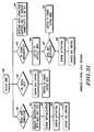
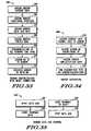
- Fig. 31is a logic diagram for a state machine running in the microcontroller/DSP computing platform in the wireless electrode transceiver assembly 20 of FIG. 2 and 3.
- the state machineWhen the device is powered up and running (and acquiring bio-potential signals), the state machine is in an active mode 400. The state machine reacts to conditions that may be present, and responds to those conditions as shown in the figure. If the user plugs the transceiver assembly into the programming pin or interface on the base unit, the state machine goes into a reset mode connection state 402. This event prompts initiation of a set of routines that request registration with the base unit, as shown in 404. After registration procedures are accomplished (described elsewhere in this document), a sensor initialization routine 406 is entered. The routine 406 is shown in FIG. 33 and described subsequently. Then, a sensor activation routine 408 is entered, shown in FIG. 34. Finally a sensor data acquisition subsystem (DAQ) control routine 410 is entered, shown in FIG. 35.
- DAQsensor data acquisition subsystem
- Another event that triggers exit of the active mode stateis when the base unit's "keep alive" or connection request signal is lost, as indicated at 412. This may occur for example when the patient moves out of range of the base unit temporarily or a problem occurs with the base unit.
- the microcontrollerenters the sensor DAQ control routine 410 and stops the acquisition of data. (This assumes that the memory size of the memory in the transceiver assembly 20 is too small to store significant amounts of data while contact with the base unit is interrupted; if sufficient memory capacity is present, the data could continued to be acquired and stored locally in the memory).
- the battery 45is then switched to a power saving mode as indicated by routine 416.
- the wireless transceiver assemblyenters a base unit registration procedure 422, wherein the transceiver assembly re-registers with the base unit. If the base unit it is attempting to register with is not its original base unit (for example where the base unit's ID is different from the original base unit ID), then a routine 424 is entered in which the battery is switched to power savings mode. If the base unit is the original base unit, the sensor activation and data acquisition subsystem routines 408 and 410 of FIG. 33 and FIG. 34 are entered.
- connection request response routine 426While the electrode is in the active mode 400 state, it will normally be receiving the periodic connection request "keep alive" messages from the base unit. It will issue responses to those connection request messages periodically, as indicated by a connection request response routine 426.
- FIG. 32is a logic diagram of a base unit state machine.
- the state machine for the base unitalso includes an active mode 450.
- the base machinewill respond to conditions including a sensor registration request condition 452. This condition may be entered during data acquisition or during initialization.
- the base unitresponds to this condition by entering the sensor initialization, activation and sensor DAQ control routines 406, 408 and 410.
- the base unitsends a connection request message to all registered wireless transceiver assemblies to insure that they are still operational and within RF range of the base unit, as indicated at 454.
- the sensoris deactivated from the system as indicated by 454. This step may be accompanied by an alarm or message on the user interface of the base unit.
- a sensor registered routine 458is entered to insure that the signal that is received originates from a registered transmitter assembly. Then, the sensor activation and DAQ control routines 408 and 410 are entered.
- a noisy uplink or downlink channelrepresented by 460.
- the base unitenters a routine 462 in which available uplink or downlink channels are scanned and a low-noise channel is selected. Then, a routine 464 is entered in which the new channel is assigned to all the registered and active wireless transceiver assemblies.
- a base unit configuration 466which can occur in response to a prompt from a user.
- the state machineenters a routine 4678 that prompts the user to enter the configuration information for the next wireless transceiver assembly.
- the sensor registration request routine 452is transmitted to the wireless transceiver assembly on the control channel or via the programming interface.
- Sensor initialization and activation routines 406 and 410are then entered. If more transceiver assemblies are to be programmed, the process returns to step 468. If all of the assemblies have been programmed and registered, as indicated by routine 470, then the system will enter a sensor DAQ control routine 410 to start data acquisition and transmission, either automatically or in response to input from the user at the base unit user interface.
- FIG. 33is a illustration of the sensor initialization routine 406 of FIG. 31.
- the routineconsists of a subroutine 500 that assigns a patient ID to the transceiver assembly.
- a subroutine 502is entered in which the functional position of the transceiver assembly is assigned by the base unit in response to user prompts.
- a sensor data acquisition rate assignment subroutine 504is then entered.
- the anti-aliasing filter bandis assigned by subroutine 506.
- the transceiver assembliesare synchronized by a global time base signal that is broadcast on the downlink channel in subroutine 508.
- the base unit IDis assigned to the transceiver assemblies by subroutine 510 and the electrode ID values are registered with the base unit in subroutine 512.
- the order of execution of modules 500, 502, 504, 506, 508, 510 and 512is not critical.
- FIG. 34illustrates the sensor activation routine 408 of FIG. 31 and 32.
- This routineincludes a subroutine 514 that assigns the current data channel to the wireless transceiver assemblies.
- a subroutine 516assigns a sensor-base unit group/transmission ID for each of the wireless transceivers.
- Transceiver amplification gainis assigned in subroutine 518.
- a subroutine 520is entered that runs diagnostic tests on the wireless transceiver assemblies and calibrates the units accordingly.
- the sensor data acquisition control routine 410is shown in FIG. 35. This routine consists of two parts, a start data acquisition subroutine and a stop data acquisition subroutine.
- the start data acquisition subroutineincludes a first module 522 that sends a command to the registered wireless transceiver assemblies to start data acquisition, and a second module 524 that commands the assemblies to start data transmission.
- the stop transmit of data subroutineincludes a first module 526 that commands the wireless transceiver to stop transmission of data, and a second module 528 that commands the data acquisition subsystem to stop acquiring data.
- Base Unitmay do any of the following during operation monitoring
- the system 10is readily adapted to acquiring other types of physiologic, chemical, physical or electrical processes, such as temperature, blood pressure, glucose, respiratory parameters, etc.
- the wireless sensorscould be either placed on the patient's body or implanted.
- the wireless transceivermay connect to a different type of physiologic sensor which converts a measured parameter to a voltage (or this functionality could be incorporated in the wireless transceiver assembly) and transmits the signal to a base unit.
Landscapes
- Health & Medical Sciences (AREA)
- Life Sciences & Earth Sciences (AREA)
- Engineering & Computer Science (AREA)
- Surgery (AREA)
- General Health & Medical Sciences (AREA)
- Veterinary Medicine (AREA)
- Biophysics (AREA)
- Pathology (AREA)
- Biomedical Technology (AREA)
- Heart & Thoracic Surgery (AREA)
- Medical Informatics (AREA)
- Molecular Biology (AREA)
- Public Health (AREA)
- Animal Behavior & Ethology (AREA)
- Physics & Mathematics (AREA)
- Physiology (AREA)
- Computer Networks & Wireless Communication (AREA)
- Human Computer Interaction (AREA)
- Measuring And Recording Apparatus For Diagnosis (AREA)
- Measurement And Recording Of Electrical Phenomena And Electrical Characteristics Of The Living Body (AREA)
- Selective Calling Equipment (AREA)
- Alarm Systems (AREA)
- Monitoring And Testing Of Transmission In General (AREA)
- Mobile Radio Communication Systems (AREA)
Abstract
Description
- This invention relates generally to the field of devices used to measure electrical bio-potential signals generated by a human body, such as electrocardiogram (ECG), electroencephalogram (EEG) and electromyography (EMG) signals. More particularly, the invention relates to a wireless signal acquisition system and over the air communications protocol that is used between a plurality of wireless, remotely programmable transceivers, each coupled to a conventional patch electrode, and an associated base unit. The base unit obtains a patient's ECG, EEG or EMG signal from the wireless transceivers and supplies the signal to monitor unit for display. The wireless communications protocol allows the base unit to remotely configure and manage the wireless transceivers, prior to and during data acquisition and transmission.
- Conventional ECG monitoring typically requires direct wired electrical connections between electrodes that are attached to the body of the patient at one end and to an ECG monitor on the other end. Electric bio-potentials are measured at the electrodes and signals are transformed via bipolar and unipolar leads into an electrocardiogram.
- Conventional ECG apparatus for hospital bedside monitoring typically requires up to ten wired electrodes. Each electrode is attached to the body of the patient, and has a wire, several feet or more in length, leading to an ECG monitor. The lengthy wired electrodes of conventional ECG apparatus obstruct the patient and limit the patient's freedom of movement. They are also cumbersome for the physician or assisting nurse.
- Telemetry systems for wireless ECG monitoring for patients in hospitals currently exist. These systems are more expensive, intended for greater range (higher power), and do not totally eliminate the physical electrode wires attached to the patient. Instead of being connected to the monitor, the electrodes are each wired to a single transmitter box that is worn by the patient. Some telemetry systems also may not handle a 12 lead ECG (10 wires) because of the wiring that is required between the electrodes and the transmitter box. For example, the Spacelabs Ultraview Modular Digital Telemetry system can only handle a maximum of four leads (5 wires).
- Wireless medical monitoring and diagnosis systems have been proposed in the prior art.
U.S. Patent 5,862,803 to Besson et al . describes a wireless electrode/sensor patch system with sensor, controller and transceiver electronics contained in an electrode patch assembly.U.S. Patents 5,307,818 ,5,168,814 and4,981,141 , all issued to Segalowitz, describe a wireless electrode system for ECG monitoring. The Besson et al. and Segalowitz patents are incorporated by reference herein. The Segalowitz patents describe a single piece electrode patch with built-in microchips for wireless one way communication, and a snap on electronic-assembly that fastens to a disposable electrode patch. However, the electrode patch is a special two-conductor type that is not conventional. The electrode assemblies are either transmit only or receive only (not both). A reference signal (generated from a Wilson network) is transmitted from the base unit to only the Right Leg electrode patch, which is receive only. Electrodes can only be programmed via manual switches on the electrode casing, not over-the-air from the base unit. For the multiple electrode embodiment, the base unit contains multiple receivers and antennas which imply multiple transmit frequencies are required for the system and over-the-air signaling (thus making the base unit more costly to implement). There is no mention of error correction or detection capability in the electrodes or base unit. - In another embodiment of the Segalowitz '818 patent, there is discussion of a single strip assembly which contains all of the electrodes required for 12-lead ECG monitoring with microchip circuitry contained in the strip assembly (not in the individual electrode patches). In this configuration, the ECG signals from each electrode are multiplexed and transmitted from a single transmitter (contained in the strip assembly) via time multiplexing on a single digitally encoded frequency channel. However, no time multiplexing on a single frequency channel is discussed for their multiple transmit electrode embodiment.
- The purpose of the invention is to define a communication protocol, i.e., set of command procedures, for a wireless (leadless) electrode system that replaces the physical wires between the electrodes attached to the patent and the monitoring system base unit. The definition of communication protocols or procedures for programming the electrodes over-the air is necessary to provide flexibility in configuring the wireless electrode system to the variable environmental conditions that exist across a wide scope of patent population, as well as different application area or needs. The wireless system allows the patient a greater degree of mobility within the neighboring area without worry about accidentally disconnecting the electrodes or being disconnected from the monitoring equipment. A wireless monitoring system also provides better patient safety since the patient is electrically isolated from the monitor. This monitoring system is also more immune to noise artifacts since the digitization process of the data occurs right at the electrode measurement point and not through extended wires. The protocol defined herein describes initialization, configuration, and management of the wireless electrode network. It also describes data acquisition and transfer to the base unit that synchronizes and coordinates electrode functions.
- An improvement to a wireless system for medical monitoring is provided. The wireless system has a base unit and a plurality of wireless sensors for attachment to a patient's body. The invention is defined in
claims - The base unit is provided with a wireless transceiver for transmitting and receiving wireless communications with the sensors. The wireless communications include, among other things, commands for the transceiver assemblies. Further, a set of instructions is provided in the base unit, such as in a memory for a base unit microcontroller, wherein the base unit issues the commands to the transceiver assemblies in response to the execution of the instructions. The commands from the base unit and the responses to those commands from the transceiver assemblies comprise a procedure or protocol by which the base unit may remotely, and automatically, manage and configure the transceiver assemblies during real time as the transceiver assemblies acquire and transmit physiologic signal data to the base unit.
- The wireless communications procedures described herein are particularly well suited for use in a system acquiring EEG, ECG or EMG signals from a human patient. The programmable wireless transceivers are associated with a sensor in the form of a conventional patch electrode, and acquire bio-potential signals between conductors in the electrode. The patch electrodes are of conventional design and adapted to be placed on the surface of the patient's body for measuring electrical bio-potentials.
- A robust wireless monitoring system needs to allow ease of configuration and calibration due to the variability of physiology across patient populations. The present invention describes wireless programming procedures that allow flexibility in configuration of telemetry based electrode system to adapt to changing requirements of different applications. This invention provides for procedures that are not only specific to ECG, but can equivalently be applied in other application areas such as EEG, EMG, EOG, Respiratory, Tonometric Blood Pressure, Temperature and other wireless medical monitoring systems. Furthermore, the programming procedures are dynamic, responsive to real time conditions as data is being acquired and transmitted to the base unit.
- The protocol provides for transmission of a variety of configuration commands. Examples of such commands include registration information, data acquisition control commands (such as start and stop messages), transmission frequency commands, time slot commands, amplifier gain commands, transmitter control commands, power saving mode commands, initialization commands, and so forth.
- The ability to remotely program the wireless transceivers gives considerable flexibility over how the electrodes are configured and positioned on the patient's body. The programmable wireless transceivers could be designed to be installed on particular locations of the patient's body, such as left arm, right arm, left leg, etc. In a more preferred embodiment, the remotely programmable electrode transceivers are generic with respect to particular placement locations on the surface of a patient's body. The base unit transmits programming data to the individual wireless transceivers. The programming data includes electrode position location data associated with a unique placement position to be assigned to the individual wireless transceivers, as well as electrode identification data. When the data is acquired from each of the wireless transceivers, the electrode identification data, electrode position location data and the acquired electrode signal are sent from the wireless transceivers to the base unit.
- The base unit and the wireless transceivers may use time division multiplexing as a communications format for transfer of the acquired signals to the base unit. In this case, the base unit transmits a global time base signal to the plurality of individual wireless transceivers. The global time base signal is used for synchronizing the timing of transmission of signals acquired by the individual wireless transceivers to the base unit in discrete time slots in a single frequency channel. This time division multiplexing provides that each wireless transceiver transmits its signals to the base unit in discrete time slots, with the wireless transceivers sharing a common frequency channel.
- These and still other aspects and features of the invention will be more apparent from the following detailed description of a presently preferred embodiment.
- In this specification, the terms "wireless transceiver" and "programmable wireless transceiver" are meant to refer to the wireless electrode transceiver assembly as a unit, as distinguished from the actual transceiver module within the assembly, unless the context clearly indicates otherwise. Further, the use of the term "electrode" is meant to be interpreted broadly to cover bio-sensors generally.
- A presently preferred embodiment of the invention is described below in conjunction with the appended drawing figures, wherein like reference numerals refer to like elements in the various views, and in which:
- FIG. 1 is a schematic representation of the system of the present invention in use with a patient to acquire ECG signals from the patient and supply them to a ECG monitor;
- FIG. 2 is a detailed perspective view of one of the patch electrodes and associated remotely programmable wireless transceiver of FIG. 1, it being understood that all of such patch electrodes and wireless transceivers of FIG. 1 are of a construction similar to that shown in FIG. 2;
- FIG. 3 is a block diagram of the wireless transceiver assembly of FIG. 2;
- FIG. 4 is a block diagram of the base unit of FIG. 1;
- FIG. 5 is a diagram illustrating the time division multiplexing of transmission format for the plurality of wireless transceivers of FIG. 1 in the uplink direction (the direction of wireless transmission from the wireless transceivers to the base unit), and the transmission of synchronization, reference and control data from the base unit to the wireless transceivers in a common channel in the downlink direction;
- FIG. 6 is a flow diagram illustrating a base unit initialization routine;
- FIG. 7 is a flow diagram illustrating a wireless transceiver initialization routine;
- FIG. 8 is a flow diagram of a programming procedure for programming the wireless transceivers of FIG. 1 when initializing the ECG system of FIG. 1;
- FIG. 9 is a perspective view of a base unit of FIG. 4 and a group of wireless transceivers being initialized according to the procedure of FIG. 8; and
- FIG. 10 is a perspective view of three wireless transmitters after the procedure of FIG. 8 has been completed;
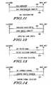
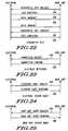
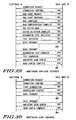
- FIGs. 11-26 are illustration of the message flow between the base unit and the electrode assemblies during various different programming procedures according to a preferred embodiment of the invention;
- FIG. 27 is an illustration of a registration procedure by which the base unit is registered with the electrode assemblies;
- FIG. 28 is an illustration of a signal loss and error recovery procedure implemented by the base unit in the event of a loss of signal from one of the electrode assemblies of FIG. 1;
- FIG. 29 is an illustration of a monitoring configuration procedure;
- FIG. 30 is an illustration of a monitoring start procedure;
- FIG. 31 is a logic diagram representing a state machine and software modules in the wireless electrode transceiver assemblies;
- FIG. 32 is a logic diagram representing a state machine and software modules in the base unit;
- FIG. 33 is a diagram of a electrode initialization with reset connection routine shown in FIG. 32;
- FIG. 34 is a diagram of an electrode activation routine shown in FIG. 32; and
- FIG. 35 is a diagram of electrode data acquisition and transmission control routines of Fig. 32.
- The present invention can be used in a system consisting of multiple smart wireless transceiver devices sized to snap onto conventional disposable patch wireless sensors or electrodes for wireless patient monitoring, and a base unit communicating with the wireless transceivers that is also capable of interfacing to existing conventional bedside monitoring equipment, such as a standard ECG or EEG monitor. The wireless transceivers receive commands from the base unit such as registration information, transmission frequency commands, amplifier gain commands, transmitter control commands, power saving mode, etc. and include hardware and software or firmware for processing these commands and responsively configuring the wireless transceiver accordingly. These commands are the result of execution of program instructions in a computing platform, such as a microcontroller, in the base unit and a set of response instructions in a computing platform in the wireless transceivers.
- A global time base signal is transmitted from the base unit to the electrodes to serve in synchronizing the timing of acquisition of sample points for all electrodes used in measuring input body surface potentials (e.g., ECG signal). In the ECG example, the base unit receives the transmitted ECG signal from each electrode (at predetermined time intervals if time division multiplexing is the embodiment of the communication protocol), demodulates, decodes (with error correction), digitally processes the data, applies any needed signal conditioning (amplification, filtering), and converts back to analog form for outputting the ECG signals to the standard ECG equipment for display. The base unit also has a universal interface to existing standard ECG equipment so that the wireless link between the electrodes and base unit appears transparent to the ECG equipment. The ECG equipment will accept the individual electrode signals for developing any required lead configuration.
- The wireless transceivers and base unit use a unique over-the-air communication protocol between the base unit and the electrodes which allows wireless programming (configuration), identification, auditing, data acquisition control, and transmitter control of each electrode used in the system during real time. For frequency bandwidth efficiency of the invention, the system could be designed such that transmission of multi-channel signals is on a single digitally encoded frequency channel between the base unit transceiver and multiple electrode devices by using time division multiplexing. For example, each electrode will receive synchronization data from the base unit on the same receive frequency, and instruction on which time slot to transmit it's digitally encoded data. This makes it possible for multiple patients each on a separate frequency channel to use the wireless system in the same hospital room if there is limited bandwidth.
- Referring now to FIG. 1, a
system 10 according to a presently preferred embodiment is shown schematically for use with apatient 12. Thesystem 10 acquires ECG, EMG, EEG or other types of signals from thepatient 12 and supplies them to amonitor 14. The present example will be discussed in terms of an ECG system, but the invention is directly applicable to other types of medical monitoring. - The
system 10 is a wireless system, in that a plurality ofelectrode assemblies 16 receive commands (e.g., synchronization and control commands) from abase unit 18 using wireless transmission methods, and supply the ECG signals to thebase unit 18 using wireless transmission methods as well. Thus, cumbersome wires for theelectrode assemblies 16 are eliminated in the illustrated embodiment. - The
electrode assemblies 16 of FIG. 1 consist of a plurality of individual, remotely programmablewireless transceiver assemblies 20, each transceiver assembly designed to snap onto a conventional patch electrode 22 (such as the 3M Red dot electrode) used in ECG monitoring. Thewireless transceivers 20 are described in further detail in conjunction with Figure 2 and 3. Thebase unit 18 includes a wireless transceiver for sending and receiving messages to the plurality of individual wireless transceivers, and is described in further detail in conjunction with Figures 4, 6, 8 and 9. The base unit further has an interface for providing analog ECG signals received from thewireless transceivers 20 to a conventional ECG display monitor 14. - A preferred communications format for wireless communication between the
base unit 18 and thewireless transceivers 20 is time division multiplexing in a common frequency channel in the uplink direction, that is between the transceivers and the base unit. Eachwireless transceiver 20 transmits ECG signals in a particular time slot in the channel, as indicated in FIG. 5. In the downlink direction, the base unit transmits control commands and other information in a common channel that all the wireless transceivers are tuned to. The time slot assignment, frequency assignment, and other transmission control information is managed and controlled by thebase unit 18, as described in further detail below. An alternative embodiment is to use code division multiple access (CDMA) communication format for wireless communication between thebase unit 18 and thewireless transceivers 20. - The messages transmitted by the
base unit 18 also include configuration commands for thewireless transceivers 20. These configuration commands can be, for example, change or set the data acquisition sampling rate, amplifier gain setting, and channel carrier settings, and can also consist of a timing signal for synchronization of the transmission time slot. Preferably, thebase unit 18 transmits a global time base signal to all of the wireless transceivers. The global time base signal synchronizes the timing of transmission of the ECG signals acquired by all of thewireless transceivers 20, such that the transmissions are in discrete time slots in a single frequency channel, as shown in FIG. 5. - The details of the over-the-air programming protocol to exchange messages and information between the base unit and the transceivers may be arrived at in many ways within the scope of the present invention, and is considered within the ability of a person skilled in the pertinent art from the present disclosure. In one possible embodiment, packets of data are transmitted between the base unit and the wireless transceivers. Particular fields in the packets (bytes of data) are reserved for control data, payload data, CRC or error correction data, etc. in accordance with known wireless transmission protocols, conventional data transmission techniques such as IP or Ethernet, or similar techniques. A presently preferred protocol and message structure is described later in this document in conjunction with FIGs. 11-30.
- FIG. 2 is a detailed perspective view of one of the
patch electrodes 22 or sensors and associated remotelyprogrammable wireless transceiver 20assembly 16 of FIG. 1, it being understood that all of such patch electrodes and wireless transceivers of FIG. 1 are of a construction similar to that shown in FIG. 2. Thepatch electrode 22 is adhered to the surface of the patient'sbody 12 in conventional fashion. Thepatch electrode 22 includes aconductor 24 supplying ECG or other signals to apin 26. Thepin 26 is received in complementarypin receiving structure 28 in thewireless transceiver 20 so as engage (as in a snap fit) the twoparts - The
pin receiving structure 28 conducts electrical impulses with respect to a local ground reference to electronic circuitry in thewireless transceiver 20. The local ground reference consists of aflexible strip 21 connected to thetransceiver 20 having a tip orskin contact 21A, made from a conductive material, which is placed underneath thepatch electrode 22 in contact with the skin. The purpose is to allow the transceiver to measure the bio-potential difference between thesignal contact point 26 and thelocal ground reference 21/21A. The material used for thestrip 21 could be a thin flexible material such as plastic with an internal conductive trace or lead wire from thetransceiver 20 to theskin contact point 21A. Theskin contact point 21A is preferably coated with conductive silver chloride (AgCl)material 21B on one side thereof. - FIG. 3 is a block diagram of the wireless transceiver of FIG.s 1 and 2. The
transceiver assembly 20 snaps onto thepost pin 26 of a disposable conventional patch electrode. Electrical signals provided from theelectrode 22 are supplied to a low noise,variable gain amplifier 30 in thewireless transceiver 20. Theamplifier 30 may include a pre-amp stage. The analog signal is filtered, sampled and converted to digital signals in the A/D converter 32. The digital signals are supplied to a computing platform, illustrated as a microcontroller/Digital Signal Processor 34. The microcontroller performs signal processing of the digital signal supplied by the A/D converter 32. The signal processing functions include noise filtering and gain control of the digital ECG signal. In an alternative but less-preferred embodiment, gain control in the transceiver assembly could be performed by adjustment of theamplifier 30 gain in the analog signal path. The microcontroller also processes commands and messages received from the base unit, and executes firmware instructions stored in amemory 36. The memory further stores a unique electrode identifier as described in further detail below. The memory may also store a position location identifier or data associated with a position the electrode is attached to the patient. The position location identifier or data is dynamically programmable from the base unit. - The processed digital ECG signals are buffered in a
buffer 38, supplied to an encoder/decoder 40 and fed to aRF transceiver module 42 for transmission to the base unit via a low power built-inRF antenna 44. Thetransceiver 42 includes a modulator/demodulator, transmitter, power amp, receiver, filters and an antenna switch. Afrequency generator 46 generates a carrier frequency for the RF transmission. The frequency is adjustable by themicrocontroller 34. Abattery 45 with a negative terminal connected to a local ground reference provides DC power to the components. The microcontroller/DSP 34 controls thefrequency generator 46 so as to select a frequency for wireless transmission of data and control messages to the base unit. The microcontroller in thecomputing platform 34 also executes an initialization routine wherein the receiver scans a default receive channel for commands from the base unit, and if the commands are received the transmitter transmits identification information in an assigned frequency and time slot to the base unit. - All or some of the individual blocks shown in FIG. 3 could be combined in a microchip or microchips to miniaturize the size of the snap-on
wireless transceiver assembly 20. - Referring now to FIG. 4, the
base unit 18 is shown also in block diagram form. Thebase unit 18 transmits commands to all of the wireless transceivers and instructs each transceiver to transmit its ECG data individually (such as in time division multiplexing). The base unit receives the transmitted ECG signals from the electrodes (up to 10) in sequence and then demodulates, decodes, error corrects, de-multiplexes, buffers, signal conditions, and reconverts each electrode's data back to an analog signal for interfacing to thestandard ECG monitor 14. The base unit also transmits programming information to the electrodes for frequency selection, power control, etc. - The
base unit 18 includes a lowpower RF antenna 50, afrequency generator 52 for generating a carrier frequency and anRF transceiver 54. Thetransceiver 54 includes a modulator/demodulator, transmitter, power amp, receiver, filters and an antenna switch. The base unit further includes a encoder/decoder 56, a computing platform such as a microcontroller/Digital Signal Processor (DSP) 58, and amemory 60 storing code for execution by the microcontroller/DSP, and I/O interface 59 for connection to a personal computer which is used as a test port for running system diagnostics, base unit software upgrades, etc., and auser interface 61. Theuser interface 61 may consist of the following: a display for indicating electrode programming information or error/alarm conditions, a keypad or buttons for user requested inputs, an alarm unit for audibly indicating error/alarm conditions (for example a detached, low battery or failed electrode), and LEDs for visually indicating error, alarm or programming status. - The time slot ECG data received from the wireless transceivers is demultiplexed in
demultiplexer 62 and supplied to abuffer 64. A digital toanalog filter bank 66 converts the multiple channels of digital data from the wireless transceivers to analog form. The analog signals are amplified byamplifiers 68 and supplied to an OEM (original equipment manufacturer) standardECG monitor interface 70. Theinterface 70 could be either part of thebase unit 18 assembly so that it can directly plug into theECG display equipment 14 via a standard connector, or it could be part of a cable connection to the display equipment. The idea with theOEM interface 70 is to supply multiple analog ECG signals to the conventional ECG display equipment already used in the hospital environment, in a compatible and transparent manner, such that the display equipment would treat the signals as if they were generated from conventional wired electrodes. Familiarity with the analog signal acquisition hardware or electronics for theECG display equipment 14 will be required obviously, and the OEM interface circuitry may vary depending on the manufacturer of the display equipment. The OEM monitor interface detailed design is considered within the ability of a person skilled in the art. - Referring to FIG. 5, a possible transmission scheme between the
wireless transceivers 20 and thebase unit 18 is time division multiplexing. This allows a single transmit frequency to be used by all the electrodes in the ECG system. All electrodes receive commands and synchronization data (time base signal, reference signal and control data 76) from thebase unit 18 on an assigned receive frequency (downlink) channel. The electrode receive channel may or may not be slotted (time multiplexed).Electrode 1 20/22A transmits it's data ontime slot 1 72 (Electrode 2 20/22B ontime slot 2 74, etc.) at the assigned transmit frequency (uplink) channel. Thebase unit 18 receives the transmission from theelectrodes 20/22 and demultiplexes, buffers, and reconstructs the individual electrode data. - The
system 10 of FIG. 1 utilizes an over the air programming mechanism to exchange messaging and information between thebase unit 18 and thewireless transceivers 20. Various types of information could be exchanged. For example, thebase unit 18 transmits a data acquisition control message to the wireless transceivers, which tells the microcontroller in the wireless transceivers to start and stop data acquisition. Another command would be a frequency selection command message(s) sent to the wireless transceivers, in which the wireless transceivers responsively select a common frequency channel for transmission of acquired ECG signals to the base unit in discrete time slots. - The following is a list of some of the possible programming commands and messages that could be sent between the base unit and the wireless transceivers:
- a. Registration of
electrodes 20/22 with thebase unit 18. This would include the detection of the electrode type and an associated unique electrode identifier by the base unit. This could also include transmission of a unique base unit identifier to the electrodes (for example where multiple base units are within RF range of the electrodes) and detection of the base unit identifier by the electrode. Also, a patient reference number could also be stored in each electrode so it only receives commands from a specific patient-assigned base unit. Each electrode reference number is also stored in the base unit, so that data coming only from these electrodes is accepted. An additional registration feature would be assignment of a specific electrode function (i.e., position on the patient's body). This is discussed in more detail below. With each of the above commands and messages, the receiving unit would typically transmit back a response message indicating the receipt of the command and sending back any required information to the transmitting unit. - b. Configuration of data acquisition sampling rate.
- c. Configuration of
amplifier 30 gain setting. - d. Configuration of preamplifier filter band settings.
- e. Configuration of carrier channel settings, namely the frequency of the carrier signal generated by the
frequency generator 46 in the transceivers. - f. Configuration of timing signal for transmission time slot. This needs to be synchronized with the data acquisition rate.
- g.
Battery 45 utilization sleep/activation mode. - h.
Battery 45 low voltage level detection. - i. Data acquisition start/stop scenario.
- j. Data transmit procedure.
- k. Error sample data recover/retransmit scenario.
- l. System test diagnostic procedure
- m. Scan of electrode current channel setting procedure
- n. Electrode detection procedure.
- o. Electrode status audit.
- p. Base unit status audit.
- q. Data acquisition subsystem audit.
- The
system 10 of FIG. 1 provides a registration mechanism for every wireless transceiver and electrode assembly whereby an electrode identifier is programmed into the base unit, as well as the electrode functional position on the patient (i.e., LA, RA, LL, V1, V2, V3, V4, V5, or V6 in an ECG embodiment). An Electrode Serial Identifier (ESI) will encode the wireless transceiver's unique serial number. Each wireless transceiver is assigned an Electrode Temporary Identifier (ETI) after each registration scenario (on power up or reconfiguration). The temporary identifier can be composed of electrode number and random number for example. The ESI will be included in each message or data transaction from each electrode to the base unit. The electrode identifier will serve to ensure that only registered electrodes input signaling will be accepted by the associated base unit, in the event that two monitoring systems are transmitting on the same frequency channel, or in the case of interference detection. - The system will provide a registration mechanism whereby a base unit identifier is programmed into the wireless transceiver assemblies being used. The Base Unit Serial Identifier (BUSI) will encode the base unit serial number. During power-up or reconfiguration, a Base Unit Temporary Identifier (BUTI) is assigned and registered with the wireless transceiver assemblies. The base unit identifier will be included in each message or data transaction from the base unit to each wireless transceiver assembly. The base unit identifier will serve to ensure that only the registered base unit input signaling (commands) will be accepted by the assemblies, in the event that two monitoring systems are transmitting on the same frequency channel, or in the case of interference detection.
- Figure 6 shows a flow diagram of a possible initialization procedure (for both the
base unit 18 andelectrodes 20/22) for use where the transmission scheme between the base unit and thewireless transceivers 20 is time division multiplexing. This procedure assumes that each electrode in the ECG system contains a unique identifier and a unique functional position ID (i.e., LA, RA, LL, V1, V2, V3, V4, V5, or V6). The procedure of FIG. 6 is reduced to a set of instructions stored in the base unit'smemory 60 for execution by themicrocontroller 58, as shown in FIG. 4, and in a set of response instructions stored in thewireless transceiver 22's memory and microcontroller of FIG. 3. - At
step 80, the base unit is powered up. The base unit is configured for the number of leads used in the ECG system, such as 3, 5 or 12. The configuration could be facilitated by means of any suitable user interface on thebase unit 18, such as a display and buttons as shown in FIG. 9 and described subsequently. Atstep 82, the base unit scans its receive channels, a list of which is programmed into the base unit. Atstep 84, the base unit determines whether any other ECG base unit transmissions are detected. If so, atstep 86 the base unit selects the next unused frequency from the list of predetermined frequency channels as a transmit channel. If not, atstep 88 the base unit selects the first frequency from the list of predetermined frequency channels as the transmission channel. The process then proceeds to step 90. - At
step 90, the base unit stars transmitting electrode registration data and messages on the default programming channel determined insteps step 92, the base unit instructs all required electrodes to transmit on a predetermined frequency channel, and assigns time slots to each electrode. The base unit then communicates with electrodes to complete registration. If a particular electrode or electrodes did not complete registration, the base unit indicates via its user interface which electrode is not registered atstep 96. If registration is completed for all the electrodes, the base units instruct all electrodes to receive commands on a new predetermined frequency channel atstep 98. Atstep 100, the base unit instructs all electrodes to begin ECG data acquisition and to transmit at the assigned frequency and in the assigned time slot. Step 100 may be started in response to a user prompt via the base unit user interface. During data acquisition, atstep 102 the base unit continuously monitors for interference on the receive data channel (uplink direction). If excessive interference occurs (such as from a high bit error rate detected in the base unit microcontroller), the base unit selects a new channel from the list of available frequencies for the electrodes to transmit on and commands a change in transmit frequency. - FIG. 7 is a flow diagram of an electrode initialization procedure that may be employed. When the electrodes are initially powered up at
step 110, the electrodes will be in a receive only mode. Atstep 112, the electrodes automatically scan the default receive channel to see if any commands and synchronization signals are being transmitted by the base unit. If no commands and synchronization commands are received atstep 114, the electrode goes back to step 112 and selects another receive frequency from its list of default frequencies. If commands and synchronization data have been received, atstep 116 the electrode sends is unique identification data (containing information on the position on the patient's body) on the assigned frequency and in the assigned time slot back to the base unit, indicating to the base unit that it is ready to acquire ECG signals and is in an operating condition. - In an alternative embodiment of the invention, the plurality of individual, remotely
programmable wireless transceivers 20 are initially generic with respect to particular placement locations on the surface of a patient's body. Furthermore, the electrodes could be manufactured without preprogrammed functional position identifiers. This is advantageous since it would not be necessary to have the hospital or user maintain an inventory of individual electrodes based on functional position (i.e., LA, RA, LL, V1, V2, etc.). All the electrode assemblies are considered generic and could be programmed with unique identifiers indicating the position on the body by the base unit when the user sets up the ECG system. The procedure of FIG. 8 could be used for programming of each electrode when initializing the ECG system. After first time programming of the electrode assemblies, the system only needs to go through the initialization program of FIG. 6 when it is powered up again. - FIG. 8 shows the initialization procedure in the alternative embodiment. FIG. 9 shows the
base unit 18 having auser interface 61 comprising adisplay 132 and a plurality of buttons orkeys 133 for assisting the user to interact with the base unit. A group ofgeneric wireless transceivers 20 are shown ready for initialization. The user has a set ofpre-printed labels 135, which are removed from a plastic backing and placed on the wireless transceivers as shown in FIG. 10. - Referring now to FIG. 8 and 9, at
step 140 the user sets up the base unit into an electrode programming mode, such as by responding to prompts on thedisplay 132 and selecting the mode with one of the buttons orkeys 133. The base unit programming mode could be done at lower power transmissions, requiring thewireless transceiver 20 to be programmed to be adjacent to the base unit (thereby avoiding programming more than one transceiver at a time). Alternatively, as shown in FIG. 9, the base unit has aprogramming initialization interface 136 which makes contact with a socket or other feature in the transceiver for purposes of programming the transceiver during initialization. When the transceiver is placed into contact with theprogramming initialization interface 136, the base unit could automatically go into programming mode, or it could simply go into programming mode upon power up. - In any event, at
step 142 thefirst electrode assembly 20/22 is powered up and placed near the base unit or positioned in contact with theprogramming initialization interface 136. The initialization of the electrodes could be done by mechanical means, such as plugging theelectrode transceiver 20 into the base unitprogramming initialization interface 136. - At
step 144, the electrode scans the default programming channel. Atstep 146, the base unit sends a low power programming command on the default transmit channel or some other channel that has the least RF interference. Atstep 148, the electrode determines whether it has received the programming command. If not, the electrode scans the list of default channels and selects a new channel to listen on. If so, the electrode transmits a response message on its assigned transmit channel atstep 150. Atstep 152, the base unit determines whether it has received the response from the electrode. If not, the base unit goes back to step 146 and transmits the low power programming command on a new transmit channel. If so, the base unit transmits programming data to the electrode atstep 153. Atstep 153, the programming data includes the electrode unique identifier, including the electrode position (LA, RL, or V3, etc.), the base unit unique identifier, and other registration commands as described above. Atstep 154, the electrode determines whether a programming error was detected, and if so atstep 156 sends a retransmit program message to base unit causing it to repeat the programming data atstep 152. If no error occurred, the process proceeds to step 158, at which the electrode completes programming with the base unit. Atstep 160, the base unit instructs the electrode to wait for additional commands. At this point, since the unique base unit ID has been programmed in the wireless transceiver, it can scan ECG system control channels and receive and operate on commands only from the base unit that programmed the transceiver. Atstep 162, the base unit displays the electrode placement position on the user interface display and prompts the user to place the next electrode for programming into theinitialization interface 136. - After all the electrodes have been programmed, the base unit will automatically be configured for the proper number of electrodes used in the ECG system. As each electrode is programmed the user removes a
label 135 from the stock oflabels 137 indicating the position programmed on the electrode and applies the label to the electrode (e.g., to the top or upper surface of the wireless transceiver 20), as shown in FIG. 10. - From the foregoing description, it will appreciated that we have described a dynamically programmable, wireless electrocardiograph (ECG) acquisition system, comprising: a plurality of individual, remotely
programmable wireless transceivers 20, each transceiver associated with apatch electrode 22 for use in ECG monitoring, and abase unit 18 comprising a wireless transceiver 54 (FIG. 4) for sending and receiving messages to the plurality ofindividual transceivers 20. The base unit andwireless transceivers 22 implement a wireless programming protocol by which messages and information are exchanged betweenbase unit 18 and wireless transceivers 20 (such as shown in FIG. 6 and 8) whereby registration, configuration, and data transmission control properties of the wireless transceivers may be managed by the base unit. - Preferably, the base unit transmits a global time base signal to the wireless transceivers, the global time base signal synchronizing the timing of transmission of ECG signals acquired by the wireless transceivers in discrete time slots in a single frequency channel. As shown in FIG. 1 and 4, the base unit further comprises an
interface 70 to a conventional ECG monitoring equipment such as a display, whereby acquired ECG signals may be transmitted to the ECG monitoring equipment for display. The system ofbase unit 18 and wireless remotelyprogrammable transceivers 20 is particularly well adapted for use with standard conventional patch electrodes and existing ECG monitoring equipment, and thus presents a flexible, low cost and convenient approach to acquiring ECG signals and presenting them to a display unit for display. - The
system 10 of FIG. 1 utilizes over the air (OTA) programming procedures to exchange messaging and information between the base unit and electrodes (that is, the wireless transceivers 20). Various types of information could be transacted for the general purposes of registration, initialization, configuration, calibration, data acquisition control, transmission synchronization, error correction or recovery, power mode control, and auditing status. - The programming procedures described herein are based on a set of instructions that are stored in a memory in the base unit (such as
memory 64 of FIG. 4), and executed by a computing platform such as themicrocontroller 58 to generate commands that are transmitted via wireless communication to the plurality of wireless electrodes. Similarly, the wireless transceivers in the electrodes receive the commands from the base unit, and execute instructions stored in a memory in order to respond to the commands and transmit response messages (such as audit response messages etc.) back to the base unit. The following is a description of these instructions. Preferred embodiments of such procedures (i.e., sets of instructions) are described below in conjunction with FIGs. 11-30: - a. Configuration of data acquisition sampling rate procedure. Variable sampling data rates could be set to accommodate varying physiologic signals (ECG, EMG, EEG, etc.). The sampling rates will differ according to the nature of frequencies evoked in such physiologic events. Also, certain application needs for specialized tests within a specific area may require faster sampling rates.
The programming procedure of FIG. 11 is employed to configure the data acquisition sampling rate. Thebase unit 18 sends a dataacquisition configuration message 200 to the electrode assembly 16 (i.e., wireless transceiver 20). The message contains data identifying a sampling rate for the wireless transceiver's A/D converter. When themessage 200 is received by the wireless transceiver and processed in the microcontroller, the sampling rate for the A/D converter is changed. The wireless transceiver sends back a data acquisition configurationcomplete message 202 indicating that the change is data sampling rate was accomplished. - b. Configuration of amplifier gain setting procedure. Variable signal preamplification gain (prior to digitization) could be set to accommodate and correct for weak bio-potential signal strength at the skin surface, or a bad surface connection, as well as changes in skin resistance due to dry or humid environmental conditions and temperature changes. The signal amplification gain factor could be adjusted dynamically until a reasonable signal strength is obtained. Typically, ECG signals re in the 1-5 mV range, while EEG signals are in the 1-100 µV range. Different gain selection is desirable to obtain the sensitivity that is needed for the specific application.
When the base unit determines that the amplifier gain needs to be adjusted, the procedure of FIG. 12 is used. The base unit sends an amplifiergain configuration message 204 to theelectrode 16's wireless transceiver 20 (FIG. 3). Themicrocontroller 32 processes the message and adjusts the gain setting to theamplifier 30 providing an analog signal to the A/D converter 32 of FIG. 3. When the gain has been adjusted, the transceiver sends a gain configurationcomplete message 206 back to the base unit. - c. Configuration of pre-amplifier (anti-aliasing) filter band settings procedure. Flexibility of adaptation of the
monitoring system 10 to variable application needs may require a dynamic re-selection of an anti-aliasing filter band in the preamplifier of the wireless transceiver. An optimal filter can be selected from a bank of filters pre-set at different frequency bands to filter out noise or unwanted artifacts. The programming procedure of FIG. 13 is employed. The base unit sends a setfilter band message 208 identifying the frequency band (or filter) for the anti-aliasing filter (not shown) in the analog signal path in the wireless transceiver. - d. Configuration of carrier channel setting procedure. In order to allow multiple users of monitoring systems to co-exist in same physical area, and at the same time reduce the possibility of interference, a multi-frequency channel system is implemented to eliminate the possibility of interference in communications between the
base unit 18 and the wireless transceivers of any givensystem 10. Thebase unit 18 dynamically detects interference by listening to a specific frequency channel during configuration, such as a default frequency channel, and determines the suitability of use for the monitoring system based on noise levels in that frequency channel. Thebase unit 18 can also apply this procedure if too many errors were encountered during the decoding of signaling received on a specific channel due to increasing noise, or during system reset and reconfiguration procedures.
The procedure of FIG. 14 is employed for carrier channel setting changes. The base unit sends a setcarrier channel message 212 to the electrode. Themessage 212 identifies the new carrier channel. The wireless transceiver's frequency generator is responsively adjusted to generate a carrier signal at the new frequency. When the configuration is complete, the electrode sends a carrier configurationcomplete message 214 back to the base unit. - e. Configuration of timing signal for transmission time slot procedure. The procedure of FIG. 15 sets the assignment of a specific time slot for each wireless transceiver (in a time division multiple access (TDMA)-based system) for transmitting and/or receiving data between the electrode's
wireless transceiver 20 and thebase unit 18. Such synchronization is necessary in a TDMA-based system to allow multiple electrodes transmitting on the same frequency channel to relay their information to the base unit without interfering with one another. The procedure consists of the base unit sending a settime slot message 216 to the electrode, identifying a particular time slot for each electrode. When the electrode has set the time slot, it sends back a time slot setcomplete message 218. - f. Battery utilization sleep/activation mode procedure. The battery utilization sleep mode procedure of FIG. 16 will be used during shut-down process for conservation of battery power. This can also be initiated if signal communication is lost between the electrodes and the base unit, or on command from the base unit. Battery utilization activation mode will be initiated as soon as communication with the electrodes is resumed or during initialization of registration of new electrodes. The procedure involves the base unit sending a battery
audit request message 220 to the electrode. Themessage 220 basically asks the electrode to provide battery life and current battery mode information. This information is provided back to the base unit in a batteryaudit response message 222. - g. Battery low voltage level detection procedure. A battery status audit procedure shown in FIG. 17 is for a condition of low battery voltage in the
wireless transceiver 20 to be detected by the base unit. The procedure allows the base unit to warn the user for replacing or recharging that electrode battery. When the voltage ofbattery 46 of FIG. 3 goes below a threshold level (as monitored by the microcontroller), the electrode sends a low battery detectedmessage 224 to the base unit. - h. Power Saving Mode Setting. The procedure shown in FIG. 18 allows the base unit to change the power saving mode of the wireless transceivers to conserve battery life and be more economical. Different levels of power saving modes can be selected based on the needs of the operation. A memory retention sleep mode can also be implemented in the wireless transceiver. The system can also have a wake up timer or change to active mode at the command of the base unit. The base unit sends a power saving mode set
command 226. The electrode responsively changes the state of thebattery 46 to a sleep or power saving mode, and when that is accomplished sends back a power saving modecomplete message 228 back to the base unit. - i. Acquisition start/stop procedure. The procedure of FIG. 19 allows the base unit to command the electrodes to start the data acquisition and transmit the data to the base unit, or stop the data acquisition process. Multiple start/stop messages of the type shown in FIG. 19 may be needed continuous data streaming of information to the base unit in the event of reconfiguration, a frequency channel re-selection is needed due to interference, or when power saving (sleep) mode is requested. Other situations are possible. The procedure begins by the base unit sending a start
data acquisition message 230 to the electrodes. The electrodes acknowledge the start of data acquisition with a acquisition startedmessage 232. The base unit then commands the electrode to start transmission of data bymessage 234. The data is sent from the electrodes as indicated bydata transfer messages 236. In this illustrated embodiment, this is by time division multiplexing on a single carrier frequency in time slots and by frequency as provided in FIGs. 14 and 15. - j. Data transmit procedure. Once data acquisition is started, data is transmitted from each of the electrodes to the base unit in either a synchronous or an asynchronous manner. This is shown in FIG. 19. At the base unit, data is decoded, collected, buffered, and checked for error occurrence during transmission.
Base unit 18 also controls the stoppage of data transmission, as shown in FIG. 20. This procedure involves the base unit sending astop acquisition message 238. The electrode ceases data acquisition and transmission and sends an acquisition stoppedmessage 240 back to the base unit. - k. Error sample data recover/retransmit procedure. In the event of an error occurring during transmission of the data from the electrodes to the base unit, the data can be requested for re-transmission. This procedure is shown in FIG. 21. The base units sends a
retransmit data message 242 to the electrode. In response, the electrode retransmits stored data stored in thememory 36, as indicated at 244. The electrode should have a minimal buffer storage of the previous data collected inbuffer 38 in the event error recovery is needed due to a noisy or bad signal transmission. - l. System test diagnostic procedure. The procedure of FIG. 22 instructs the electrodes to transmit a diagnostic test data pattern in order to analyze the system for optimal performance. Also, it may be used to resolve issues in local ground referencing across all electrodes for calibration purposes. A diagnostic test initiate
message 246 is sent from the base unit to the electrode. Receipt of themessage 246 causes the microcontroller to initiate certain tests or transmit a diagnostic test pattern according to a set of instructions or code stored in thememory 68 designed to respond to themessage 246. A test initiatedmessage 248 is sent back to the base unit, acknowledging themessage 246. After the test is performed, test data is transmitted to the base unit as indicated at 250. When all of the test data has been received, the base unit sends a testcomplete message 252 to the electrode, and the message is acknowledged by a test completedmessage 254. - m. Scan of electrode current channel setting procedure. A procedure may be implemented to allow the base unit to scan for an electrode that is transmitting on an unknown frequency channel. Using a signal strength indicator, the specific transmission channel can be determined. The electrode can be reconfigured to transmit on a new channel using the procedure of FIG. 14.
- n. Electrode detection procedure. The procedure of FIG. 23 is initiated periodically, as a means of providing a continuous search and "keep-alive" signal. The electrode detection procedure involves a
connection message 256 that is transmitted from the base unit to the electrodes. The electrodes respond with aconnection confirm message 258 which tells the base unit that the electrode is "alive". If thiselectrode detection message 256 is not received periodically by the electrodes, then they stop data acquisition and move into a power saving mode. The signaling can be done on an interval basis (e.g., every 30 seconds) and on the last previously selected traffic channel. - o. Electrode Status Audit: A procedure shown in FIG. 24 allow the electrode status to be audited by the base unit when needed to ensure proper operating conditions and configuration parameters. The procedure involves the base unit sending an electrode
audit request message 260. The electrode responds to the audit message with anaudit response message 262 indicating current operating conditions and configuration parameters, e.g., gain setting, preamplification filter band, reference signal, time slot, carrier frequency, data acquisition rate, serial number, etc. - p. Base Unit Audit. Referring to FIG. 25, a base unit's status can be audited by the electrodes when needed to ensure proper operating conditions and configuration parameters. The electrodes send a base unit
audit request message 264 to the base unit and it responds with anaudit message 266 indicating its current configuration parameters, such as channel frequency. - q. Data acquisition subsystem audit. Referring to FIG. 26, the data acquisition subsystem in the wireless transceivers, consisting of the preamplifier, amplifier and D/A converter, can be individually audited for proper operation status and configuration settings. The base unit sends a data acquisition (DAQ)
audit request message 268 to the electrode and the information is provided in a DAQaudit response message 250. - a. Registration of electrodes with the base unit. A preferred registration procedure includes (but is not limited to) detection of electrode type and identifier. The patient reference number and/or demographics can also be stored in each electrode so they are associated uniquely with a specific patient. Assignment of electrode function (anatomical or functional position) in this monitoring system is also performed. Assignment of any temporary identifiers to the electrodes can also be performed. The registration procedure can be initiated on a dedicated frequency control channel(s) for initialization. The registration procedures of FIG.s 6 and 8 are one possible embodiment of the registration procedure. Another possible embodiment in shown in FIG. 27. The base unit sends a
connection request message 272 to the electrodes. The electrodes reply with aconnection confirm message 274. This is the procedure of FIG. 23 described previously. Thenelectrode audit messages Function allocation message 280 that assigns the electrode with a temporary ID and body position or function. The electrode sends an allocationcomplete message 282 in response to theallocation message 280. A baseunit registration message 284 is sent to the electrode, registering the electrode with the base and conveying the base unit identification to the electrode. A base unit registrationcomplete message 286 is sent in response.Messages - b. Registration of the base unit with the electrodes. A registration procedure may be implemented by which the base unit registers with the electrodes is also performed. The procedure is shown in
messages messages - c. Total signal loss recovery scenario. A procedure shown in FIG. 28 is provided which recovers from a total loss of signal from one or more of the electrodes. The procedure is initiated in the event of weakening transmission signal strength due to fading channels, or low available transmission power, or large physical distance between the electrodes and the base unit. A continuous search and "keep-alive" signal is transmitted from the base unit to the electrodes. Once an electrode is detected, communication is re-established, and the base unit resumes collection of the data. The procedure begins with the connection request and confirm
messages 306 and 308 (the procedure of FIG. 23 described previously), theelectrode audit messages 310 and 312 (the procedure of FIG. 24), and the data acquisitionsubsystem audit messages 314 and 314 (the procedure of FIG. 26). Depending on the response to the audit messages, the base unit may initiate any number of configuration commands to restore the electrode to a proper operating condition, such as the DAQ configuremessage 316 which configures the data acquisition subsystem in the wireless transceiver. The electrode sends thecomplete message 318 when the subsystem has been reconfigured in accordance with the settings contained in themessage 316. As another alternative, the setcarrier channel messages messages messages 338 and 334 (the procedure of FIG. 12). Any or all of the messages shown in dashed lines could be implemented. After a successful reconfiguration of the electrode, data acquisition and transmission is reestablished bymessages - d. Monitoring system configuration scenario: A procedure shown in FIG. 29 is provided for the overall monitoring system configuration. The
system 10 will set up and configure multiple subsystems including: data acquisition, filtering and signal conditioning, amplifier gain setting, and run diagnostic tests to ensure quality of transmitted data. The configuration begins by a connection request message and response connection confirm message 350 (the procedure of FIG. 23), the data acquisitionsubsystem audit messages 352 and 354 (the procedure of FIG. 26), the data acquisitionsubsystem configuration messages messages 360 and 362 (the procedure of FIG. 13). Then a diagnostic test procedure consisting ofmessages message 376 depending on the results of the diagnostic test just performed. When the amplifier gain is successfully changed the gain configurationcomplete message 378 is sent back to the base unit. - e. Monitoring system data acquisition start scenario: The system will start the data acquisition and transmission through the traffic channel to the base unit once system configuration is complete. The procedure of FIG. 30 shows one possible embodiment. A
configuration request message 380 is sent, generating theconfiguration confirm message 382 from the electrode (procedure of FIG. 23). Data acquisition startmessages messages amplifier 30 in the wireless transceiver can be adjusted via amplifiergain configuration message 392 and when the change is made a gain configurationcomplete message 394 is sent back to the base unit. - Fig. 31 is a logic diagram for a state machine running in the microcontroller/DSP computing platform in the wireless
electrode transceiver assembly 20 of FIG. 2 and 3. When the device is powered up and running (and acquiring bio-potential signals), the state machine is in anactive mode 400. The state machine reacts to conditions that may be present, and responds to those conditions as shown in the figure. If the user plugs the transceiver assembly into the programming pin or interface on the base unit, the state machine goes into a resetmode connection state 402. This event prompts initiation of a set of routines that request registration with the base unit, as shown in 404. After registration procedures are accomplished (described elsewhere in this document), asensor initialization routine 406 is entered. The routine 406 is shown in FIG. 33 and described subsequently. Then, asensor activation routine 408 is entered, shown in FIG. 34. Finally a sensor data acquisition subsystem (DAQ)control routine 410 is entered, shown in FIG. 35. - Another event that triggers exit of the active mode state is when the base unit's "keep alive" or connection request signal is lost, as indicated at 412. This may occur for example when the patient moves out of range of the base unit temporarily or a problem occurs with the base unit. When this occurs, the microcontroller enters the sensor
DAQ control routine 410 and stops the acquisition of data. (This assumes that the memory size of the memory in thetransceiver assembly 20 is too small to store significant amounts of data while contact with the base unit is interrupted; if sufficient memory capacity is present, the data could continued to be acquired and stored locally in the memory). Thebattery 45 is then switched to a power saving mode as indicated byroutine 416. - Another event that can occur is the base unit's signal is regained as indicated by
condition 418. When this occurs, the state machine returns toactive mode 400, as indicated byroutine 420. The wireless transceiver assembly enters a baseunit registration procedure 422, wherein the transceiver assembly re-registers with the base unit. If the base unit it is attempting to register with is not its original base unit (for example where the base unit's ID is different from the original base unit ID), then a routine 424 is entered in which the battery is switched to power savings mode. If the base unit is the original base unit, the sensor activation and dataacquisition subsystem routines - While the electrode is in the
active mode 400 state, it will normally be receiving the periodic connection request "keep alive" messages from the base unit. It will issue responses to those connection request messages periodically, as indicated by a connectionrequest response routine 426. - FIG. 32 is a logic diagram of a base unit state machine. The state machine for the base unit also includes an
active mode 450. The base machine will respond to conditions including a sensorregistration request condition 452. This condition may be entered during data acquisition or during initialization. The base unit responds to this condition by entering the sensor initialization, activation and sensorDAQ control routines - If the signal from one of the wireless transceiver assemblies is lost, as indicated by
condition 453, then the sensor is deactivated from the system as indicated by 454. This step may be accompanied by an alarm or message on the user interface of the base unit. - If the signal is regained, as indicated by
condition 456, a sensor registeredroutine 458 is entered to insure that the signal that is received originates from a registered transmitter assembly. Then, the sensor activation andDAQ control routines - Another condition that can occur is a noisy uplink or downlink channel, represented by 460. When this occurs, the base unit enters a routine 462 in which available uplink or downlink channels are scanned and a low-noise channel is selected. Then, a routine 464 is entered in which the new channel is assigned to all the registered and active wireless transceiver assemblies.
- Another event that can occur is a
base unit configuration 466, which can occur in response to a prompt from a user. When this condition occurs, the state machine enters a routine 4678 that prompts the user to enter the configuration information for the next wireless transceiver assembly. The sensorregistration request routine 452 is transmitted to the wireless transceiver assembly on the control channel or via the programming interface. Sensor initialization andactivation routines DAQ control routine 410 to start data acquisition and transmission, either automatically or in response to input from the user at the base unit user interface. - FIG. 33 is a illustration of the
sensor initialization routine 406 of FIG. 31. The routine consists of asubroutine 500 that assigns a patient ID to the transceiver assembly. Next, asubroutine 502 is entered in which the functional position of the transceiver assembly is assigned by the base unit in response to user prompts. A sensor data acquisitionrate assignment subroutine 504 is then entered. The anti-aliasing filter band is assigned bysubroutine 506. Then the transceiver assemblies are synchronized by a global time base signal that is broadcast on the downlink channel insubroutine 508. Then, the base unit ID is assigned to the transceiver assemblies bysubroutine 510 and the electrode ID values are registered with the base unit insubroutine 512. The order of execution ofmodules - FIG. 34 illustrates the
sensor activation routine 408 of FIG. 31 and 32. This routine includes asubroutine 514 that assigns the current data channel to the wireless transceiver assemblies. Asubroutine 516 assigns a sensor-base unit group/transmission ID for each of the wireless transceivers. Transceiver amplification gain is assigned insubroutine 518. Then, asubroutine 520 is entered that runs diagnostic tests on the wireless transceiver assemblies and calibrates the units accordingly. - The sensor data
acquisition control routine 410 is shown in FIG. 35. This routine consists of two parts, a start data acquisition subroutine and a stop data acquisition subroutine. The start data acquisition subroutine includes afirst module 522 that sends a command to the registered wireless transceiver assemblies to start data acquisition, and asecond module 524 that commands the assemblies to start data transmission. The stop transmit of data subroutine includes afirst module 526 that commands the wireless transceiver to stop transmission of data, and asecond module 528 that commands the data acquisition subsystem to stop acquiring data. - The following is a pseudocode listing of system initialization and operations management routines for the base unit and the electrodes, as an alternative embodiment to the procedures of FIGs. 6 and 8.
If no pre-stored channels is selected (first-time power up) or connection is in reset mode Electrodes scan pre-set dedicated channel(s) for input signaling from base unit. Else Start using pre-stored temporary transmit and receive channels for messaging. End
If no pre-stored channels are selected, or reset mode connection is requested, or current traffic Channel interference is high Base Unit scans and selects a low-noise temporary transmit traffic channel for all electrodes to transmit signaling on. Base Unit scans and selects a low-noise temporary receive traffic channel for all electrodes to receive signaling on. Else Use previously stored transmit and receive channels End Base Unit periodically transmits signaling on pre-set dedicated channel(s) if electrode is not registered or disconnected, and listens (scans) for electrode response. All other transmission occurs on temporary traffic channels. Send "keep-alive" signaling and scan for response from an electrode, then For each electrode required for current configuration settings, once detected (connection established) Electrode is assigned a temporary identifier. Electrode is associated with patient demographics info. Electrode is assigned a functional or anatomic position in the monitoring system. Electrode is requested to move to a new temporary transmit traffic frequency channel and time slot. Electrode is requested to move to a new temporary receive traffic frequency channel (and time slot if any). End End If all required electrodes are registered and connected Electrodes are assigned a (default/selected) data acquisition rate. Electrodes are assigned a (default/selected) amplification gain setting. Electrodes are assigned a (default/selected) filter band setting. Run diagnostic system test to ensure quality of recordings Adjust amplification gain on electrodes until suitable signal strength is obtained. Adjust filter selection until good signal/noise ratio is obtained. Run synchronization tests to ensure system is properly synchronized for transfer of data test patterns. End Start data acquisition and monitoring. End
Monitors and tracks for interference and bit error rate on current channel setting, if too many errors request retransmission of data in error due to interference, or if too many errors then select and move to new temporary transmit and/or receive channels, Stops / restarts data acquisition for measured signals. Senses signal strength and re-adjust signal amplification gain dynamically toenable good resolution on the A/D channels. Interrupts data acquisition for reconfiguration or re-initialization procedures. Switches electrode(s) into power saving mode or reactivates electrode(s)operation.
Claims (28)
- A method for medical monitoring in a wireless system, the wireless system having a base unit (18) and at least one wireless sensor for connection to a patient's (12) body, the method comprising:providing said wireless sensor with a transceiver assembly (20) for transmitting and receiving wireless communications with said base unit (18);providing the base unit (18) with a wireless transceiver (54) for transmitting and receiving wireless communications with said sensors, said wireless communications including commands; andproviding a set of instructions executable in said base unit (18) wherein said base unit (18) may issue said commands to said transceiver assembly (20) in response to the execution of said instructions, said transceiver assembly (20) responding to said commands in accordance with instructions stored in said transceiver;wherein said commands from said base unit (18) and responses to said commands from said transceiver assembly allow said base unit (18) to remotely manage and configure said transceiver assembly (20) in real time either prior to or during a period of time in which said transceiver assembly (20) is acquiring physiologic signals from said patient (12) and transmitting data corresponding to said physiologic signals to said base unit (18);
wherein said commands include an assignment of an identification number of said wireless transceiver and an assignment of a functional position of said wireless sensors on said patient (12). - The method of claim 1, wherein said commands comprise a data acquisition sampling rate command, and
wherein said transceiver assembly (20) configures circuitry in said transceiver assembly sampling data acquired from said wireless sensor in response to said data acquisition sampling rate command. - The method of claim 1, wherein said command comprises a filter band selection command, and wherein said transceiver assembly (20) selects an anti-aliasing filter in said transceiver assembly (20) in response to said filter band selection command.
- The method of claim 1, wherein said transceiver assembly (20) further comprises a battery (45) and wherein said transceiver assembly (20) sends a low battery detection message to said base unit (18) when the level in said battery (45) falls below a predetermined threshold.
- The method of claim 1, wherein said command comprises a power saving mode command, and wherein said transceiver assembly (20) changes a state of battery (45) consumption in said transceiver assembly (20) to a power saving mode in response to said power saving mode command.
- The method of claim 1, wherein said command comprises a start data transmission command, and wherein said transceiver assembly (20) commences transmission of said data to said base unit (18) in response to said start data transmit command.
- The method of claim 6, wherein said data is transmitted to said base unit (18) in time slots and in a frequency channel assigned to said transceiver assembly (20) from said base unit (18).
- The method of claim 1, wherein said command comprises a diagnostic test initiation command, said transceiver assembly (20) commencing a predetermined diagnostic test routine and sending diagnostic test data to said base unit (18) in response to said diagnostic test initiation command.
- The method of claim 1, wherein said command comprises a data acquisition subsystem audit command, said transceiver assembly (20) transmitting an audit of current data acquisition subsystem configuration parameters in response to said data acquisition subsystem audit command.
- The method of claim 1, wherein said commands comprise a set of commands establishing a registration of said transceiver assembly (20) with said base unit (18), said set of commands including as assignment of an identification number of said wireless transceiver (54), an assignment of functional position of said wireless electrode on said patient (12) and an assignment of a base unit (18) identification to said transceiver assembly (20).
- The method of claim 1, wherein said wireless sensors comprise a plurality of individual wireless electrodes, each associated with one of said transceiver assemblies (20), and wherein said plurality of wireless electrodes, transceiver assemblies (20) and said base unit (18) comprise a wireless electrocardiogram data acquisition system.
- A wireless electrocardiogram data acquisition system, comprising:a set of wireless sensors for attachment to a patient's (12) body, each of said wireless sensors coupled to a transceiver assembly (20) for transmitting and receiving wireless communications;a base unit (18) comprising a wireless transceiver (54) for transmitting and receiving wireless communications with said transceiver assemblies (20), said wireless communications including a set of commands for said transceiver assemblies (20);said base unit (18) further comprising a memory (60) and computing platform executing a set of instructions wherein said base unit (18) may issue said commands to individual ones of said transceiver assemblies (20) in response to the execution of said instructions;each of said transceiver assemblies (20) further comprising a memory (36) and a computing platform for responding to said commands in accordance with instructions stored in said memory (36) in said transceiver assembly(20);wherein said commands from said base unit (18) and responses to said commands from said transceiver assemblies (20) allow said base unit (18) to remotely and individually manage and configure each of said transceiver assemblies (20) in real time either prior to or during a period of time in which said transceiver assemblies (20) are acquiring physiologic electrocardiogram signals from said patient (12) and transmitting data corresponding to said physiologic electrocardiogram signals to said base unit (18);
wherein said commands include an assignment of an identification number of said wireless transceiver and an assignment of a functional position of said wireless sensors on said patient (12). - The system of claim 12, wherein said commands comprise a data acquisition sampling rate command, and wherein said transceiver assemblies (20) configure circuitry in said transceiver assembly (20) sampling data acquired from said wireless electrode in response to said data acquisition sampling rate command.
- The system of claim 12, wherein said command comprises a filter band selection command, and wherein each of said transceiver assemblies (20) selects an anti-aliasing filter in said transceiver assembly (20) in response to said filter band selection command.
- The system of claim 12, wherein said transceiver assembly (20) further comprises a battery (35) and wherein each of said transceiver assemblies (20) sends a low battery detection message to said base unit (18) when the level in said battery falls to a predetermined threshold.
- The system of claim 12, wherein said command comprises a power saving mode command, and wherein said transceiver assemblies (20) change a state of battery consumption in said transceiver assembly (20) to a power saving mode in response to said power saving mode command.
- The system of claim 12, wherein said command comprises a start data transmission command, and wherein said transceiver assemblies (20) commences transmission of said data to said base unit (18) in response to said start data transmission command.
- The system of claim 12, wherein said data is transmitted to said base unit (18) in time slots and in a frequency channel assigned to said transceiver assembly (20) from said base unit (18).
- The system of claim 12, wherein said command comprises a diagnostic test initiation command, said transceiver assemblies commencing a predetermined diagnostic test routine and sending diagnostic test data to said base unit (18) in response to said diagnostic test initiation command.
- The system of claim 12, wherein said commands comprise a data acquisition subsystem audit command, said transceiver assemblies (20) transmitting an audit of current data acquisition subsystem configuration parameters in response to said data acquisition subsystem audit command.
- The system of claim 12, wherein said commands comprise a set of commands establishing a registration of said transceiver assemblies (20) with said base unit (18), said set of commands include an assignment of an identification number of said transceiver assemblies (20), an assignment of a functional position of said wireless electrode on said patient (12) and the assignment of a base unit (18) identification to said transceiver assembly (20).
- The system of claim 12, wherein said commands comprise a set of commands establishing a signal loss recovery procedure by which said base unit (18) may reestablish communication with one of said transceiver assemblies (20) in the event of a total signal loss from said transceiver assembly (20).
- A machine-readable storage medium containing a set of instructions executable in a base unit (18) for over-the air programming of a plurality of wireless transceivers (20), each of the said wireless transceivers (20) adapted to couple to a sensor for connection to a patient's (12) body;
said set of instructions generating commands for remotely configuring and managing the acquisition of physiologic signals from said patient's (12) body and transmission of said physiologic signals from said wireless transceivers (20) to said base unit (18) in real time either prior to or during a period in which said physiologic signals are being acquired;
wherein said commands include an assignment of an identification number of said wireless transceiver and an assignment of a functional position of said wireless sensors on said patient (12). - The machine-readable storage medium of claim 23, wherein said wireless transceivers (20) comprise a machine-readable storage medium containing a set of instructions for responding to the commands.
- The machine-readable storage medium of claim 23, wherein said set of instructions prompt said base unit (18) to generate a set of registration commands and wherein said wireless transceivers (20) comprise a machine-readable storage medium containing a set of instructions for responding to said set of registration instructions.
- The machine-readable storage medium of claim 23, wherein said set of instructions prompt said base unit (18) to generate a set of signal loss recovery commands and wherein said wireless transceivers (20) comprise a machine-readable storage medium containing a set of instructions for responding to said set of signal loss recovery commands.
- The machine-readable storage medium of claim 23, wherein said set of instructions prompt said base unit (18) to configure the data transmission properties of said wireless transceivers (20).
- The machine-readable storage medium of claim 23, wherein said set of instructions include a base unit (18) configuration routine wherein said base unit (18) programs patient (12) identification and position location information into said wireless transceiver assembly (20).
Applications Claiming Priority (3)
| Application Number | Priority Date | Filing Date | Title |
|---|---|---|---|
| US551719 | 2000-04-18 | ||
| US09/551,719US6441747B1 (en) | 2000-04-18 | 2000-04-18 | Wireless system protocol for telemetry monitoring |
| PCT/US2001/012562WO2001078831A2 (en) | 2000-04-18 | 2001-04-17 | Wireless system protocol for telemetry monitoring |
Publications (3)
| Publication Number | Publication Date |
|---|---|
| EP1290658A2 EP1290658A2 (en) | 2003-03-12 |
| EP1290658A4 EP1290658A4 (en) | 2004-12-22 |
| EP1290658B1true EP1290658B1 (en) | 2008-01-30 |
Family
ID=24202401
Family Applications (1)
| Application Number | Title | Priority Date | Filing Date |
|---|---|---|---|
| EP01930556AExpired - LifetimeEP1290658B1 (en) | 2000-04-18 | 2001-04-17 | Wireless system protocol for telemetry monitoring |
Country Status (10)
| Country | Link |
|---|---|
| US (2) | US6441747B1 (en) |
| EP (1) | EP1290658B1 (en) |
| JP (1) | JP4863422B2 (en) |
| AT (1) | ATE385184T1 (en) |
| AU (2) | AU5708301A (en) |
| CA (1) | CA2405861C (en) |
| DE (1) | DE60132665T2 (en) |
| ES (1) | ES2300328T3 (en) |
| MX (1) | MXPA02010273A (en) |
| WO (1) | WO2001078831A2 (en) |
Families Citing this family (785)
| Publication number | Priority date | Publication date | Assignee | Title |
|---|---|---|---|---|
| DE4329898A1 (en) | 1993-09-04 | 1995-04-06 | Marcus Dr Besson | Wireless medical diagnostic and monitoring device |
| US6266623B1 (en) | 1994-11-21 | 2001-07-24 | Phatrat Technology, Inc. | Sport monitoring apparatus for determining loft time, speed, power absorbed and other factors such as height |
| US7386401B2 (en) | 1994-11-21 | 2008-06-10 | Phatrat Technology, Llc | Helmet that reports impact information, and associated methods |
| US8280682B2 (en) | 2000-12-15 | 2012-10-02 | Tvipr, Llc | Device for monitoring movement of shipped goods |
| US7786562B2 (en)* | 1997-11-11 | 2010-08-31 | Volkan Ozguz | Stackable semiconductor chip layer comprising prefabricated trench interconnect vias |
| US20020180605A1 (en)* | 1997-11-11 | 2002-12-05 | Ozguz Volkan H. | Wearable biomonitor with flexible thinned integrated circuit |
| US20050096513A1 (en)* | 1997-11-11 | 2005-05-05 | Irvine Sensors Corporation | Wearable biomonitor with flexible thinned integrated circuit |
| EP1030590B1 (en)* | 1997-12-04 | 2002-10-23 | Roche Diagnostics Corporation | Method of configuring a hand-held instrument |
| US6036924A (en) | 1997-12-04 | 2000-03-14 | Hewlett-Packard Company | Cassette of lancet cartridges for sampling blood |
| US20030036746A1 (en) | 2001-08-16 | 2003-02-20 | Avi Penner | Devices for intrabody delivery of molecules and systems and methods utilizing same |
| US6391005B1 (en) | 1998-03-30 | 2002-05-21 | Agilent Technologies, Inc. | Apparatus and method for penetration with shaft having a sensor for sensing penetration depth |
| US6949816B2 (en) | 2003-04-21 | 2005-09-27 | Motorola, Inc. | Semiconductor component having first surface area for electrically coupling to a semiconductor chip and second surface area for electrically coupling to a substrate, and method of manufacturing same |
| US6175752B1 (en) | 1998-04-30 | 2001-01-16 | Therasense, Inc. | Analyte monitoring device and methods of use |
| US8465425B2 (en) | 1998-04-30 | 2013-06-18 | Abbott Diabetes Care Inc. | Analyte monitoring device and methods of use |
| US8974386B2 (en) | 1998-04-30 | 2015-03-10 | Abbott Diabetes Care Inc. | Analyte monitoring device and methods of use |
| US8688188B2 (en) | 1998-04-30 | 2014-04-01 | Abbott Diabetes Care Inc. | Analyte monitoring device and methods of use |
| US8346337B2 (en) | 1998-04-30 | 2013-01-01 | Abbott Diabetes Care Inc. | Analyte monitoring device and methods of use |
| US9066695B2 (en) | 1998-04-30 | 2015-06-30 | Abbott Diabetes Care Inc. | Analyte monitoring device and methods of use |
| US8480580B2 (en) | 1998-04-30 | 2013-07-09 | Abbott Diabetes Care Inc. | Analyte monitoring device and methods of use |
| US8882666B1 (en) | 1998-05-08 | 2014-11-11 | Ideal Life Inc. | Personal health monitoring and/or communication system |
| US9375573B2 (en)* | 1998-08-05 | 2016-06-28 | Cyberonics, Inc. | Systems and methods for monitoring a patient's neurological disease state |
| US9320900B2 (en) | 1998-08-05 | 2016-04-26 | Cyberonics, Inc. | Methods and systems for determining subject-specific parameters for a neuromodulation therapy |
| US7747325B2 (en) | 1998-08-05 | 2010-06-29 | Neurovista Corporation | Systems and methods for monitoring a patient's neurological disease state |
| US7209787B2 (en) | 1998-08-05 | 2007-04-24 | Bioneuronics Corporation | Apparatus and method for closed-loop intracranial stimulation for optimal control of neurological disease |
| CA2345043C (en)* | 1998-10-08 | 2009-08-11 | Minimed, Inc. | Telemetered characteristic monitor system |
| US20060202859A1 (en)* | 1998-10-08 | 2006-09-14 | Mastrototaro John J | Telemetered characteristic monitor system and method of using the same |
| US6441747B1 (en)* | 2000-04-18 | 2002-08-27 | Motorola, Inc. | Wireless system protocol for telemetry monitoring |
| US6496705B1 (en) | 2000-04-18 | 2002-12-17 | Motorola Inc. | Programmable wireless electrode system for medical monitoring |
| BR0110596A (en) | 2000-05-05 | 2005-08-02 | Hill Rom Services Inc | Patient monitoring system, computer system, patient information monitoring system, patient care device, walker device, patient care device, and computer display |
| EP1290652A2 (en) | 2000-05-05 | 2003-03-12 | Hill-Rom Services, Inc. | Hospital monitoring and control system and method |
| US6738670B1 (en) | 2000-06-19 | 2004-05-18 | Medtronic, Inc. | Implantable medical device telemetry processor |
| EP1303213A4 (en) | 2000-07-18 | 2008-04-02 | Motorola Inc | Wireless electrocardiograph system and method |
| US8797165B2 (en) | 2000-10-11 | 2014-08-05 | Riddell, Inc. | System for monitoring a physiological parameter of players engaged in a sporting activity |
| US10952671B2 (en) | 2000-10-11 | 2021-03-23 | Riddell, Inc. | System for monitoring a physiological parameter of players engaged in a sporting activity |
| US6826509B2 (en)* | 2000-10-11 | 2004-11-30 | Riddell, Inc. | System and method for measuring the linear and rotational acceleration of a body part |
| US7024248B2 (en) | 2000-10-16 | 2006-04-04 | Remon Medical Technologies Ltd | Systems and methods for communicating with implantable devices |
| US6628968B1 (en)* | 2000-11-02 | 2003-09-30 | Ericsson Inc. | Providing timing reference for radio heads |
| US6810270B1 (en)* | 2000-11-02 | 2004-10-26 | Ericsson Inc. | Providing reference signal to radio heads |
| US8641644B2 (en) | 2000-11-21 | 2014-02-04 | Sanofi-Aventis Deutschland Gmbh | Blood testing apparatus having a rotatable cartridge with multiple lancing elements and testing means |
| DE10057832C1 (en) | 2000-11-21 | 2002-02-21 | Hartmann Paul Ag | Blood analysis device has syringe mounted in casing, annular mounting carrying needles mounted behind test strip and being swiveled so that needle can be pushed through strip and aperture in casing to take blood sample |
| US6970917B1 (en)* | 2000-12-05 | 2005-11-29 | Mformation Technologies Inc. | System and method for remote control and management of wireless devices |
| US7343408B2 (en)* | 2000-12-05 | 2008-03-11 | Mformation Technologies, Inc. | System and method for wireless data terminal management using telecommunication signaling network |
| US20020112047A1 (en)* | 2000-12-05 | 2002-08-15 | Rakesh Kushwaha | System and method for wireless data terminal management using general packet radio service network |
| US20020112046A1 (en)* | 2000-12-05 | 2002-08-15 | Rakesh Kushwaha | System and method for wireless data terminal management using mobitex network |
| US7171331B2 (en) | 2001-12-17 | 2007-01-30 | Phatrat Technology, Llc | Shoes employing monitoring devices, and associated methods |
| US7181285B2 (en) | 2000-12-26 | 2007-02-20 | Cardiac Pacemakers, Inc. | Expert system and method |
| US6560471B1 (en) | 2001-01-02 | 2003-05-06 | Therasense, Inc. | Analyte monitoring device and methods of use |
| US20060064140A1 (en)* | 2001-01-30 | 2006-03-23 | Whitehurst Todd K | Methods and systems for stimulating a trigeminal nerve to treat a psychiatric disorder |
| EP1374194A2 (en) | 2001-03-30 | 2004-01-02 | Hill-Rom Services, Inc. | Hospital bed and network system |
| US6694158B2 (en)* | 2001-04-11 | 2004-02-17 | Motorola, Inc. | System using a portable detection device for detection of an analyte through body tissue |
| US8337419B2 (en) | 2002-04-19 | 2012-12-25 | Sanofi-Aventis Deutschland Gmbh | Tissue penetration device |
| US7981056B2 (en) | 2002-04-19 | 2011-07-19 | Pelikan Technologies, Inc. | Methods and apparatus for lancet actuation |
| US9226699B2 (en) | 2002-04-19 | 2016-01-05 | Sanofi-Aventis Deutschland Gmbh | Body fluid sampling module with a continuous compression tissue interface surface |
| JP4272051B2 (en) | 2001-06-12 | 2009-06-03 | ペリカン テクノロジーズ インコーポレイテッド | Blood sampling apparatus and method |
| US9795747B2 (en) | 2010-06-02 | 2017-10-24 | Sanofi-Aventis Deutschland Gmbh | Methods and apparatus for lancet actuation |
| US7749174B2 (en) | 2001-06-12 | 2010-07-06 | Pelikan Technologies, Inc. | Method and apparatus for lancet launching device intergrated onto a blood-sampling cartridge |
| US7041068B2 (en) | 2001-06-12 | 2006-05-09 | Pelikan Technologies, Inc. | Sampling module device and method |
| US7344507B2 (en) | 2002-04-19 | 2008-03-18 | Pelikan Technologies, Inc. | Method and apparatus for lancet actuation |
| JP4209767B2 (en) | 2001-06-12 | 2009-01-14 | ペリカン テクノロジーズ インコーポレイテッド | Self-optimized cutting instrument with adaptive means for temporary changes in skin properties |
| US9427532B2 (en) | 2001-06-12 | 2016-08-30 | Sanofi-Aventis Deutschland Gmbh | Tissue penetration device |
| WO2002101359A2 (en) | 2001-06-12 | 2002-12-19 | Pelikan Technologies, Inc. | Integrated blood sampling analysis system with multi-use sampling module |
| AU2002344825A1 (en) | 2001-06-12 | 2002-12-23 | Pelikan Technologies, Inc. | Method and apparatus for improving success rate of blood yield from a fingerstick |
| EP1395185B1 (en) | 2001-06-12 | 2010-10-27 | Pelikan Technologies Inc. | Electric lancet actuator |
| US7044911B2 (en)* | 2001-06-29 | 2006-05-16 | Philometron, Inc. | Gateway platform for biological monitoring and delivery of therapeutic compounds |
| US7197357B2 (en)* | 2001-07-17 | 2007-03-27 | Life Sync Corporation | Wireless ECG system |
| US7933642B2 (en)* | 2001-07-17 | 2011-04-26 | Rud Istvan | Wireless ECG system |
| JP2004538078A (en)* | 2001-08-20 | 2004-12-24 | インバネス・メディカル・リミテッド | Wireless diabetes management device and method of using wireless diabetes management device |
| US9326695B1 (en)* | 2004-11-12 | 2016-05-03 | Orbital Research Inc | Electrode harness and method of taking biopotential measurements |
| US7344894B2 (en) | 2001-10-16 | 2008-03-18 | Agilent Technologies, Inc. | Thermal regulation of fluidic samples within a diagnostic cartridge |
| US7383088B2 (en) | 2001-11-07 | 2008-06-03 | Cardiac Pacemakers, Inc. | Centralized management system for programmable medical devices |
| US6993393B2 (en) | 2001-12-19 | 2006-01-31 | Cardiac Pacemakers, Inc. | Telemetry duty cycle management system for an implantable medical device |
| US7729776B2 (en) | 2001-12-19 | 2010-06-01 | Cardiac Pacemakers, Inc. | Implantable medical device with two or more telemetry systems |
| US6985773B2 (en) | 2002-02-07 | 2006-01-10 | Cardiac Pacemakers, Inc. | Methods and apparatuses for implantable medical device telemetry power management |
| US8391989B2 (en) | 2002-12-18 | 2013-03-05 | Cardiac Pacemakers, Inc. | Advanced patient management for defining, identifying and using predetermined health-related events |
| US7043305B2 (en) | 2002-03-06 | 2006-05-09 | Cardiac Pacemakers, Inc. | Method and apparatus for establishing context among events and optimizing implanted medical device performance |
| US7468032B2 (en) | 2002-12-18 | 2008-12-23 | Cardiac Pacemakers, Inc. | Advanced patient management for identifying, displaying and assisting with correlating health-related data |
| US20040122294A1 (en) | 2002-12-18 | 2004-06-24 | John Hatlestad | Advanced patient management with environmental data |
| US8043213B2 (en) | 2002-12-18 | 2011-10-25 | Cardiac Pacemakers, Inc. | Advanced patient management for triaging health-related data using color codes |
| US20040122487A1 (en) | 2002-12-18 | 2004-06-24 | John Hatlestad | Advanced patient management with composite parameter indices |
| US7983759B2 (en) | 2002-12-18 | 2011-07-19 | Cardiac Pacemakers, Inc. | Advanced patient management for reporting multiple health-related parameters |
| JP2003275183A (en)* | 2002-03-25 | 2003-09-30 | Matsushita Electric Ind Co Ltd | Biological information detection sensor and sensor control device |
| US6850788B2 (en) | 2002-03-25 | 2005-02-01 | Masimo Corporation | Physiological measurement communications adapter |
| US7136703B1 (en) | 2002-04-16 | 2006-11-14 | Pacesetter, Inc. | Programmer and surface ECG system with wireless communication |
| US7331931B2 (en) | 2002-04-19 | 2008-02-19 | Pelikan Technologies, Inc. | Method and apparatus for penetrating tissue |
| US8579831B2 (en) | 2002-04-19 | 2013-11-12 | Sanofi-Aventis Deutschland Gmbh | Method and apparatus for penetrating tissue |
| US7909778B2 (en) | 2002-04-19 | 2011-03-22 | Pelikan Technologies, Inc. | Method and apparatus for penetrating tissue |
| US7708701B2 (en) | 2002-04-19 | 2010-05-04 | Pelikan Technologies, Inc. | Method and apparatus for a multi-use body fluid sampling device |
| US7232451B2 (en) | 2002-04-19 | 2007-06-19 | Pelikan Technologies, Inc. | Method and apparatus for penetrating tissue |
| US7582099B2 (en) | 2002-04-19 | 2009-09-01 | Pelikan Technologies, Inc | Method and apparatus for penetrating tissue |
| US8267870B2 (en) | 2002-04-19 | 2012-09-18 | Sanofi-Aventis Deutschland Gmbh | Method and apparatus for body fluid sampling with hybrid actuation |
| US7141058B2 (en) | 2002-04-19 | 2006-11-28 | Pelikan Technologies, Inc. | Method and apparatus for a body fluid sampling device using illumination |
| US9795334B2 (en) | 2002-04-19 | 2017-10-24 | Sanofi-Aventis Deutschland Gmbh | Method and apparatus for penetrating tissue |
| US7291117B2 (en) | 2002-04-19 | 2007-11-06 | Pelikan Technologies, Inc. | Method and apparatus for penetrating tissue |
| US7410468B2 (en) | 2002-04-19 | 2008-08-12 | Pelikan Technologies, Inc. | Method and apparatus for penetrating tissue |
| US7229458B2 (en) | 2002-04-19 | 2007-06-12 | Pelikan Technologies, Inc. | Method and apparatus for penetrating tissue |
| US7491178B2 (en) | 2002-04-19 | 2009-02-17 | Pelikan Technologies, Inc. | Method and apparatus for penetrating tissue |
| US7976476B2 (en) | 2002-04-19 | 2011-07-12 | Pelikan Technologies, Inc. | Device and method for variable speed lancet |
| US7481776B2 (en) | 2002-04-19 | 2009-01-27 | Pelikan Technologies, Inc. | Method and apparatus for penetrating tissue |
| US8221334B2 (en) | 2002-04-19 | 2012-07-17 | Sanofi-Aventis Deutschland Gmbh | Method and apparatus for penetrating tissue |
| US8784335B2 (en) | 2002-04-19 | 2014-07-22 | Sanofi-Aventis Deutschland Gmbh | Body fluid sampling device with a capacitive sensor |
| US7901362B2 (en) | 2002-04-19 | 2011-03-08 | Pelikan Technologies, Inc. | Method and apparatus for penetrating tissue |
| US7717863B2 (en) | 2002-04-19 | 2010-05-18 | Pelikan Technologies, Inc. | Method and apparatus for penetrating tissue |
| US7674232B2 (en) | 2002-04-19 | 2010-03-09 | Pelikan Technologies, Inc. | Method and apparatus for penetrating tissue |
| US9314194B2 (en) | 2002-04-19 | 2016-04-19 | Sanofi-Aventis Deutschland Gmbh | Tissue penetration device |
| US7648468B2 (en) | 2002-04-19 | 2010-01-19 | Pelikon Technologies, Inc. | Method and apparatus for penetrating tissue |
| US7892183B2 (en) | 2002-04-19 | 2011-02-22 | Pelikan Technologies, Inc. | Method and apparatus for body fluid sampling and analyte sensing |
| US7547287B2 (en) | 2002-04-19 | 2009-06-16 | Pelikan Technologies, Inc. | Method and apparatus for penetrating tissue |
| US7524293B2 (en) | 2002-04-19 | 2009-04-28 | Pelikan Technologies, Inc. | Method and apparatus for penetrating tissue |
| US9248267B2 (en) | 2002-04-19 | 2016-02-02 | Sanofi-Aventis Deustchland Gmbh | Tissue penetration device |
| US7297122B2 (en) | 2002-04-19 | 2007-11-20 | Pelikan Technologies, Inc. | Method and apparatus for penetrating tissue |
| US8702624B2 (en) | 2006-09-29 | 2014-04-22 | Sanofi-Aventis Deutschland Gmbh | Analyte measurement device with a single shot actuator |
| US7374544B2 (en) | 2002-04-19 | 2008-05-20 | Pelikan Technologies, Inc. | Method and apparatus for penetrating tissue |
| US7563232B2 (en) | 2002-04-19 | 2009-07-21 | Pelikan Technologies, Inc. | Method and apparatus for penetrating tissue |
| US7371247B2 (en) | 2002-04-19 | 2008-05-13 | Pelikan Technologies, Inc | Method and apparatus for penetrating tissue |
| US20030220673A1 (en)* | 2002-05-24 | 2003-11-27 | Snell Jeffrey D. | Multi-device telemetry architecture |
| AT411400B (en)* | 2002-05-31 | 2003-12-29 | Hoffmann La Roche | METHOD AND DEVICE FOR MEASURING BLOOD GAS PARAMETERS |
| US20030229274A1 (en)* | 2002-06-07 | 2003-12-11 | Barnes-Jewish Hospital | Electromyograph having telemetry |
| GB0214439D0 (en)* | 2002-06-21 | 2002-07-31 | Neurodan As | Transmitter or receiver mounting |
| JP2004024551A (en)* | 2002-06-26 | 2004-01-29 | Renesas Technology Corp | Semiconductor device for sensor system |
| US20040186357A1 (en)* | 2002-08-20 | 2004-09-23 | Welch Allyn, Inc. | Diagnostic instrument workstation |
| US20050288571A1 (en) | 2002-08-20 | 2005-12-29 | Welch Allyn, Inc. | Mobile medical workstation |
| US7294105B1 (en) | 2002-09-03 | 2007-11-13 | Cheetah Omni, Llc | System and method for a wireless medical communication system |
| US7259906B1 (en) | 2002-09-03 | 2007-08-21 | Cheetah Omni, Llc | System and method for voice control of medical devices |
| SE523545C2 (en)* | 2002-09-19 | 2004-04-27 | Foss Tecator Ab | Method, a portable device and a measuring instrument for standardizing a satellite measuring instrument to a corresponding main measuring instrument |
| KR20040032451A (en)* | 2002-10-09 | 2004-04-17 | 삼성전자주식회사 | Mobile device having health care function and method of health care using the same |
| AU2003263476A1 (en)* | 2002-10-11 | 2004-05-04 | Koninklijke Philips Electronics N.V. | Power saving uplink for biosensors |
| ES2328806T3 (en)* | 2002-10-11 | 2009-11-18 | Becton, Dickinson And Company | INSULIN RELEASE SYSTEM WITH SENSOR. |
| GB2394294A (en)* | 2002-10-18 | 2004-04-21 | Cambridge Neurotechnology Ltd | Cardiac sensor with accelerometer |
| US20040100376A1 (en)* | 2002-11-26 | 2004-05-27 | Kimberly-Clark Worldwide, Inc. | Healthcare monitoring system |
| US7395117B2 (en)* | 2002-12-23 | 2008-07-01 | Cardiac Pacemakers, Inc. | Implantable medical device having long-term wireless capabilities |
| US8574895B2 (en) | 2002-12-30 | 2013-11-05 | Sanofi-Aventis Deutschland Gmbh | Method and apparatus using optical techniques to measure analyte levels |
| US7811231B2 (en)* | 2002-12-31 | 2010-10-12 | Abbott Diabetes Care Inc. | Continuous glucose monitoring system and methods of use |
| US7378955B2 (en)* | 2003-01-03 | 2008-05-27 | Cardiac Pacemakers, Inc. | System and method for correlating biometric trends with a related temporal event |
| US7136707B2 (en) | 2003-01-21 | 2006-11-14 | Cardiac Pacemakers, Inc. | Recordable macros for pacemaker follow-up |
| EP2374406B1 (en)* | 2003-01-30 | 2013-06-05 | Accenture Global Services Limited | Event data acquisition and transmission system |
| CN100448393C (en)* | 2003-04-10 | 2009-01-07 | 皇家飞利浦电子股份有限公司 | Method and elements for reliably assigning network elements to wireless sensor networks |
| US20060142808A1 (en)* | 2003-04-22 | 2006-06-29 | Christopher Pearce | Defibrillator/monitor system having a pod with leads capable of wirelessly communicating |
| US8310201B1 (en)* | 2003-05-06 | 2012-11-13 | Cypress Semiconductor Corporation | Battery with electronic compartment |
| US20040224718A1 (en)* | 2003-05-09 | 2004-11-11 | Chen Yu Yu | Multifunctional body/motion signal receiving and display device |
| US7130583B2 (en)* | 2003-05-14 | 2006-10-31 | Battelle Memorial Institute | Wireless communication devices and movement monitoring methods |
| US7850621B2 (en) | 2003-06-06 | 2010-12-14 | Pelikan Technologies, Inc. | Method and apparatus for body fluid sampling and analyte sensing |
| JP3878152B2 (en)* | 2003-06-10 | 2007-02-07 | 日本電信電話株式会社 | Electric field utilization monitoring system |
| US8066639B2 (en) | 2003-06-10 | 2011-11-29 | Abbott Diabetes Care Inc. | Glucose measuring device for use in personal area network |
| WO2006001797A1 (en) | 2004-06-14 | 2006-01-05 | Pelikan Technologies, Inc. | Low pain penetrating |
| EP1635700B1 (en) | 2003-06-13 | 2016-03-09 | Sanofi-Aventis Deutschland GmbH | Apparatus for a point of care device |
| DE10329846B4 (en) | 2003-07-02 | 2009-01-15 | Disetronic Licensing Ag | System and method for communication monitoring |
| WO2005006956A2 (en)* | 2003-07-09 | 2005-01-27 | Medical Technologies Unlimited, Inc. | Comprehensive neuromuscular profiler |
| US8034294B1 (en) | 2003-07-15 | 2011-10-11 | Ideal Life, Inc. | Medical monitoring/consumables tracking device |
| US8795168B2 (en)* | 2003-07-17 | 2014-08-05 | Cadi Scientific Pte Ltd. | Method and system for capturing and monitoring a physiological parameter and movement within an area of at least one person |
| US20050020889A1 (en)* | 2003-07-24 | 2005-01-27 | Garboski Dennis P. | Medical monitoring system |
| US7238156B1 (en) | 2003-07-31 | 2007-07-03 | At&T Intellectual Property, Inc. | Systems, methods, and devices for health monitoring |
| US8571880B2 (en)* | 2003-08-07 | 2013-10-29 | Ideal Life, Inc. | Personal health management device, method and system |
| WO2005022692A2 (en) | 2003-08-21 | 2005-03-10 | Hill-Rom Services, Inc. | Plug and receptacle having wired and wireless coupling |
| US20050066335A1 (en)* | 2003-09-23 | 2005-03-24 | Robert Aarts | System and method for exposing local clipboard functionality towards external applications |
| US8282576B2 (en) | 2003-09-29 | 2012-10-09 | Sanofi-Aventis Deutschland Gmbh | Method and apparatus for an improved sample capture device |
| US9259584B2 (en)* | 2003-10-02 | 2016-02-16 | Medtronic, Inc. | External unit for implantable medical device coupled by cord |
| EP1680014A4 (en) | 2003-10-14 | 2009-01-21 | Pelikan Technologies Inc | METHOD AND DEVICE FOR A VARIABLE USER INTERFACE |
| US7101343B2 (en)* | 2003-11-05 | 2006-09-05 | Temple University Of The Commonwealth System Of Higher Education | Implantable telemetric monitoring system, apparatus, and method |
| CN1886091B (en)* | 2003-12-02 | 2011-07-13 | 皇家飞利浦电子股份有限公司 | Medical measuring device |
| US10413742B2 (en) | 2008-03-05 | 2019-09-17 | Physio-Control, Inc. | Defibrillator patient monitoring pod |
| US8600491B2 (en)* | 2003-12-17 | 2013-12-03 | Physio-Control, Inc. | Defibrillator patient monitoring pod |
| US8788038B2 (en)* | 2003-12-17 | 2014-07-22 | Physio-Control, Inc. | External defibrillator with power and battery sharing capabilities with a pod |
| US7957798B2 (en) | 2003-12-17 | 2011-06-07 | Physio-Control, Inc. | Defibrillator/monitor system having a pod with leads capable of wirelessly communicating |
| WO2005062232A2 (en)* | 2003-12-19 | 2005-07-07 | Philips Intellectual Property & Standards Gmbh | Patient network with wireless medical apparatuses and allocation thereof to a patient and his network |
| US7822454B1 (en) | 2005-01-03 | 2010-10-26 | Pelikan Technologies, Inc. | Fluid sampling device with improved analyte detecting member configuration |
| US8668656B2 (en) | 2003-12-31 | 2014-03-11 | Sanofi-Aventis Deutschland Gmbh | Method and apparatus for improving fluidic flow and sample capture |
| US20070149246A1 (en)* | 2004-01-09 | 2007-06-28 | Revolabs, Inc. | Wireless multi-user audio system |
| US8483757B2 (en)* | 2004-01-09 | 2013-07-09 | Revo Labs, Inc. | Wireless multi-user audio system |
| US20060217162A1 (en)* | 2004-01-09 | 2006-09-28 | Bodley Martin R | Wireless multi-user audio system |
| WO2005089103A2 (en) | 2004-02-17 | 2005-09-29 | Therasense, Inc. | Method and system for providing data communication in continuous glucose monitoring and management system |
| WO2005086331A2 (en) | 2004-03-02 | 2005-09-15 | Rosemount, Inc. | Process device with improved power generation |
| DE102004012042B4 (en)* | 2004-03-10 | 2008-04-10 | Smiths Medical Deutschland Gmbh | Patient monitoring device |
| WO2005094674A1 (en)* | 2004-03-29 | 2005-10-13 | Neuronetrix, Inc. | Active, multiplexed digital electrodes for eeg, ecg and emg applications |
| EP1735879A2 (en)* | 2004-03-30 | 2006-12-27 | Hi-G-Tek Ltd | Monitorable locking assemblies |
| EP1732643B1 (en)* | 2004-04-07 | 2013-02-27 | Cardiac Pacemakers, Inc. | System and method for rf transceiver duty cycling in an implantable medical device |
| WO2005099817A1 (en) | 2004-04-07 | 2005-10-27 | Cardiac Pacemakers, Inc. | Rf wake-up of implantable medical device |
| US20050237197A1 (en)* | 2004-04-23 | 2005-10-27 | Liebermann Howard H | Detection of articles having substantially rectangular cross-sections |
| JP2007534399A (en)* | 2004-04-28 | 2007-11-29 | ユニヴェルシテ・レンヌ・デスカルト−パリ・サンク | Apparatus and method for measuring skin potential |
| US8538560B2 (en) | 2004-04-29 | 2013-09-17 | Rosemount Inc. | Wireless power and communication unit for process field devices |
| US20050261559A1 (en)* | 2004-05-18 | 2005-11-24 | Mumford John R | Wireless physiological monitoring system |
| WO2006011062A2 (en) | 2004-05-20 | 2006-02-02 | Albatros Technologies Gmbh & Co. Kg | Printable hydrogel for biosensors |
| US8145180B2 (en) | 2004-05-21 | 2012-03-27 | Rosemount Inc. | Power generation for process devices |
| WO2005120365A1 (en) | 2004-06-03 | 2005-12-22 | Pelikan Technologies, Inc. | Method and apparatus for a fluid sampling device |
| US7794499B2 (en) | 2004-06-08 | 2010-09-14 | Theken Disc, L.L.C. | Prosthetic intervertebral spinal disc with integral microprocessor |
| US8195304B2 (en) | 2004-06-10 | 2012-06-05 | Medtronic Urinary Solutions, Inc. | Implantable systems and methods for acquisition and processing of electrical signals |
| US7239918B2 (en)* | 2004-06-10 | 2007-07-03 | Ndi Medical Inc. | Implantable pulse generator for providing functional and/or therapeutic stimulation of muscles and/or nerves and/or central nervous system tissue |
| US7173437B2 (en)* | 2004-06-10 | 2007-02-06 | Quantum Applied Science And Research, Inc. | Garment incorporating embedded physiological sensors |
| US9308382B2 (en)* | 2004-06-10 | 2016-04-12 | Medtronic Urinary Solutions, Inc. | Implantable pulse generator systems and methods for providing functional and/or therapeutic stimulation of muscles and/or nerves and/or central nervous system tissue |
| US8165692B2 (en) | 2004-06-10 | 2012-04-24 | Medtronic Urinary Solutions, Inc. | Implantable pulse generator power management |
| US9205255B2 (en) | 2004-06-10 | 2015-12-08 | Medtronic Urinary Solutions, Inc. | Implantable pulse generator systems and methods for providing functional and/or therapeutic stimulation of muscles and/or nerves and/or central nervous system tissue |
| EP1758499B1 (en)* | 2004-06-15 | 2013-12-25 | Philips Intellectual Property & Standards GmbH | Sensors for acquiring physiological signals of a patient |
| US8744564B2 (en)* | 2004-06-18 | 2014-06-03 | Impedimed Limited | Oedema detection |
| US7262693B2 (en) | 2004-06-28 | 2007-08-28 | Rosemount Inc. | Process field device with radio frequency communication |
| US8160535B2 (en) | 2004-06-28 | 2012-04-17 | Rosemount Inc. | RF adapter for field device |
| US7206630B1 (en)* | 2004-06-29 | 2007-04-17 | Cleveland Medical Devices, Inc | Electrode patch and wireless physiological measurement system and method |
| US20060001538A1 (en)* | 2004-06-30 | 2006-01-05 | Ulrich Kraft | Methods of monitoring the concentration of an analyte |
| US20060001551A1 (en)* | 2004-06-30 | 2006-01-05 | Ulrich Kraft | Analyte monitoring system with wireless alarm |
| CA2477615A1 (en)* | 2004-07-15 | 2006-01-15 | Quantum Applied Science And Research, Inc. | Unobtrusive measurement system for bioelectric signals |
| US7319386B2 (en) | 2004-08-02 | 2008-01-15 | Hill-Rom Services, Inc. | Configurable system for alerting caregivers |
| US7743151B2 (en)* | 2004-08-05 | 2010-06-22 | Cardiac Pacemakers, Inc. | System and method for providing digital data communications over a wireless intra-body network |
| US20060036137A1 (en)* | 2004-08-13 | 2006-02-16 | John Lewicke | Patient monitoring apparatus |
| US7438687B2 (en)* | 2004-08-14 | 2008-10-21 | Nova Technology Corporation | Patient monitoring system with blood pressure measurement capacity |
| US20060041196A1 (en)* | 2004-08-17 | 2006-02-23 | Quasar, Inc. | Unobtrusive measurement system for bioelectric signals |
| US20060066449A1 (en)* | 2004-09-08 | 2006-03-30 | Industrial Widget Works Company | RFMON: devices and methods for wireless monitoring of patient vital signs through medical sensor readings from passive RFID tags |
| US20060064133A1 (en) | 2004-09-17 | 2006-03-23 | Cardiac Pacemakers, Inc. | System and method for deriving relative physiologic measurements using an external computing device |
| US7532933B2 (en) | 2004-10-20 | 2009-05-12 | Boston Scientific Scimed, Inc. | Leadless cardiac stimulation systems |
| DE602005011847D1 (en)* | 2004-11-08 | 2009-01-29 | Philips Intellectual Property | SAFE IDENTIFICATION AND ASSIGNMENT OF WIRELESS SENSORS |
| CN101073083B (en)* | 2004-11-12 | 2012-04-25 | 皇家飞利浦电子股份有限公司 | Message Integrity for Reliable Communication of Wireless Medical Devices |
| US7813808B1 (en) | 2004-11-24 | 2010-10-12 | Remon Medical Technologies Ltd | Implanted sensor system with optimized operational and sensing parameters |
| US20100197233A1 (en)* | 2004-12-14 | 2010-08-05 | Andrew Joo Kim | Method and System for Automatic Control in an Interference Cancellation Device |
| US20070239230A1 (en)* | 2004-12-17 | 2007-10-11 | Medtronic, Inc. | System and method for regulating cardiac triggered therapy to the brain |
| US7656853B2 (en)* | 2004-12-27 | 2010-02-02 | Microsoft Corporation | Reducing power consumption of a wireless device |
| US8652831B2 (en) | 2004-12-30 | 2014-02-18 | Sanofi-Aventis Deutschland Gmbh | Method and apparatus for analyte measurement test time |
| ITBO20050002A1 (en)* | 2005-01-04 | 2006-07-05 | Giacomo Vespasiani | METHOD AND SYSTEM FOR INTERACTIVE MANAGEMENT OF DATA CONCERNING AN INSULIN THERAPY IN SELF-CONTROL FOR A DIABETIC PATIENT |
| MX2007008304A (en) | 2005-01-07 | 2008-01-18 | Riddell | System and method for evaluating and providing treatment to sports participants. |
| US20060161222A1 (en)* | 2005-01-15 | 2006-07-20 | Haubrich Gregory J | Multiple band communications for an implantable medical device |
| US7218969B2 (en)* | 2005-01-19 | 2007-05-15 | Cardiac Pacemakers, Inc. | Dynamic channel selection for RF telemetry with implantable device |
| FI20055027L (en)* | 2005-01-19 | 2006-07-20 | Polar Electro Oy | System, performance meter, server and computer program |
| US7545272B2 (en) | 2005-02-08 | 2009-06-09 | Therasense, Inc. | RF tag on test strips, test strip vials and boxes |
| EP1864473B1 (en)* | 2005-03-22 | 2008-09-03 | Koninklijke Philips Electronics N.V. | Addressing scheme for smart wireless medical sensor networks |
| JP2006268614A (en)* | 2005-03-25 | 2006-10-05 | Sony Corp | System, apparatus and method for processing information, program, and recording medium |
| JP4403512B2 (en)* | 2005-03-29 | 2010-01-27 | ソニー株式会社 | Information processing system, information processing apparatus and method, program, and recording medium |
| US8046072B2 (en) | 2005-03-31 | 2011-10-25 | Medtronic, Inc. | Prioritization of communications from medical devices |
| US7595697B2 (en)* | 2005-04-15 | 2009-09-29 | Ivy Biomedical Systems, Inc. | Wireless transmitter |
| US8480577B2 (en)* | 2005-04-15 | 2013-07-09 | Ivy Biomedical Systems, Inc. | Wireless patient monitoring system |
| WO2006113911A2 (en)* | 2005-04-19 | 2006-10-26 | Willis Richard A | Apparatus and method to monitor body temperature |
| GB2425601B (en) | 2005-04-26 | 2008-01-30 | Bio Nano Sensium Technologies | Sensor configuration |
| US7664553B2 (en) | 2005-04-27 | 2010-02-16 | Cardiac Pacemakers, Inc. | System and method for enabling communications with implantable medical devices |
| US8802183B2 (en) | 2005-04-28 | 2014-08-12 | Proteus Digital Health, Inc. | Communication system with enhanced partial power source and method of manufacturing same |
| US8836513B2 (en) | 2006-04-28 | 2014-09-16 | Proteus Digital Health, Inc. | Communication system incorporated in an ingestible product |
| US9198608B2 (en) | 2005-04-28 | 2015-12-01 | Proteus Digital Health, Inc. | Communication system incorporated in a container |
| EP3827747A1 (en) | 2005-04-28 | 2021-06-02 | Otsuka Pharmaceutical Co., Ltd. | Pharma-informatics system |
| US8730031B2 (en) | 2005-04-28 | 2014-05-20 | Proteus Digital Health, Inc. | Communication system using an implantable device |
| US8912908B2 (en) | 2005-04-28 | 2014-12-16 | Proteus Digital Health, Inc. | Communication system with remote activation |
| US20060247549A1 (en)* | 2005-04-29 | 2006-11-02 | Idt Technology Limited | Wireless heart rate monitoring system |
| US7398379B1 (en)* | 2005-05-02 | 2008-07-08 | Altera Corporation | Programmable logic device integrated circuits with wireless programming |
| DE102005021000B4 (en)* | 2005-05-03 | 2014-09-04 | Krohne Meßtechnik GmbH & Co KG | gauge |
| US7843830B1 (en)* | 2005-05-05 | 2010-11-30 | Force 10 Networks, Inc | Resilient retransmission of epoch data |
| WO2007032786A2 (en)* | 2005-05-11 | 2007-03-22 | Medical Technologies Unlimited, Inc. | Apparatus for converting electromyographic (emg) signals for transference to a personal computer |
| JP2006350993A (en)* | 2005-05-17 | 2006-12-28 | Sony Corp | Selling device, selling method, and program |
| JP2006323498A (en)* | 2005-05-17 | 2006-11-30 | Sony Corp | Management system, management method, information processor, and information processing method |
| GB2422197B (en) | 2005-05-17 | 2007-08-08 | Bio Nano Sensium Technologies | Sensor calibration |
| US8391990B2 (en) | 2005-05-18 | 2013-03-05 | Cardiac Pacemakers, Inc. | Modular antitachyarrhythmia therapy system |
| FI20055240L (en)* | 2005-05-20 | 2006-11-21 | Polar Electro Oy | Per-user performance meter peripheral device, per-user performance meter and method |
| US20060276702A1 (en)* | 2005-06-03 | 2006-12-07 | Mcginnis William | Neurophysiological wireless bio-sensor |
| JP4524647B2 (en)* | 2005-06-14 | 2010-08-18 | ソニー株式会社 | COMMUNICATION DEVICE, COMMUNICATION METHOD, AND PROGRAM |
| JP2006352700A (en)* | 2005-06-17 | 2006-12-28 | Sony Corp | System, apparatus, method, and program for communication |
| JP2006352699A (en)* | 2005-06-17 | 2006-12-28 | Sony Corp | Communication system, communication apparatus and method, and program |
| RU2389056C2 (en)* | 2005-06-27 | 2010-05-10 | Роузмаунт Инк. | Field device with radio-frequency connection, in which consumed power is controlled dynamically |
| US20110054343A1 (en) | 2005-07-01 | 2011-03-03 | Impedimed Limited | Monitoring system |
| EP2460468A1 (en) | 2005-07-01 | 2012-06-06 | Impedimed Limited | Monitoring system |
| EP1903938A4 (en) | 2005-07-01 | 2010-01-20 | Impedance Cardiology Systems I | Pulmonary monitoring system |
| US20070010748A1 (en)* | 2005-07-06 | 2007-01-11 | Rauch Steven D | Ambulatory monitors |
| KR100738074B1 (en)* | 2005-07-16 | 2007-07-10 | 삼성전자주식회사 | Health care device and method |
| US20070021945A1 (en)* | 2005-07-20 | 2007-01-25 | Frank Riskey | Systems and methods for use in remote data collection, such as for use with atmospheric data collection devices |
| US20070032989A1 (en)* | 2005-07-20 | 2007-02-08 | Hodges Mark E | Managing information collected in real-time or near real-time, such as sensor information used in the testing and measurement of environments and systems |
| US8461958B2 (en)* | 2005-08-17 | 2013-06-11 | Wireless Data Solutions, Llc | System for monitoring and control of transport containers |
| US7801620B2 (en)* | 2005-08-29 | 2010-09-21 | Cardiac Pacemakers, Inc. | RF telemetry link quality assessment system and method |
| US8027727B2 (en)* | 2005-08-29 | 2011-09-27 | Cardiac Pacemakers, Inc. | Pacemaker RF telemetry repeater and method |
| US8547248B2 (en) | 2005-09-01 | 2013-10-01 | Proteus Digital Health, Inc. | Implantable zero-wire communications system |
| US7742815B2 (en) | 2005-09-09 | 2010-06-22 | Cardiac Pacemakers, Inc. | Using implanted sensors for feedback control of implanted medical devices |
| US7890181B2 (en)* | 2005-09-12 | 2011-02-15 | Medtronic, Inc. | System and method for unscheduled wireless communication with a medical device |
| US8380320B2 (en)* | 2005-09-12 | 2013-02-19 | Medtronic, Inc. | Implantable medical device communication system with macro and micro sampling intervals |
| US8185210B2 (en)* | 2005-09-12 | 2012-05-22 | Medtronic, Inc. | Communication system and method with preamble encoding for an implantable medical device |
| US8065018B2 (en) | 2005-09-12 | 2011-11-22 | Medtronic, Inc. | System and method for unscheduled wireless communication with a medical device |
| CN100489716C (en)* | 2005-09-21 | 2009-05-20 | 国际商业机器公司 | Method and sampling device for processing measure flow data |
| US7760082B2 (en)* | 2005-09-21 | 2010-07-20 | Chon Meng Wong | System and method for active monitoring and diagnostics of life signs using heartbeat waveform and body temperature remotely giving the user freedom to move within its vicinity without wires attachment, gel, or adhesives |
| US20070073132A1 (en)* | 2005-09-27 | 2007-03-29 | Michael Vosch | Apparatus and method for monitoring patients |
| US20070080223A1 (en)* | 2005-10-07 | 2007-04-12 | Sherwood Services Ag | Remote monitoring of medical device |
| JP5208749B2 (en) | 2005-10-11 | 2013-06-12 | インペダイムド・リミテッド | Hydration status monitoring |
| US9168383B2 (en) | 2005-10-14 | 2015-10-27 | Pacesetter, Inc. | Leadless cardiac pacemaker with conducted communication |
| EP1948296B2 (en) | 2005-10-14 | 2017-10-11 | Pacesetter, Inc. | Leadless cardiac pacemaker and system |
| US7911339B2 (en) | 2005-10-18 | 2011-03-22 | Apple Inc. | Shoe wear-out sensor, body-bar sensing system, unitless activity assessment and associated methods |
| US20070091813A1 (en)* | 2005-10-19 | 2007-04-26 | Guy Richard | Automatic channel switching method for low-power communication devices |
| US10299668B2 (en) | 2005-10-21 | 2019-05-28 | Physio-Control, Inc. | Laryngoscope with handle-grip activated recording |
| US8160704B2 (en)* | 2005-11-02 | 2012-04-17 | Cardiac Pacemakers, Inc. | System and method for enabling relayed communications by implantable medical devices |
| US7766829B2 (en) | 2005-11-04 | 2010-08-03 | Abbott Diabetes Care Inc. | Method and system for providing basal profile modification in analyte monitoring and management systems |
| US7595723B2 (en)* | 2005-11-14 | 2009-09-29 | Edwards Lifesciences Corporation | Wireless communication protocol for a medical sensor system |
| US20070112274A1 (en)* | 2005-11-14 | 2007-05-17 | Edwards Lifesciences Corporation | Wireless communication system for pressure monitoring |
| US8972017B2 (en) | 2005-11-16 | 2015-03-03 | Bioness Neuromodulation Ltd. | Gait modulation system and method |
| US7632239B2 (en) | 2005-11-16 | 2009-12-15 | Bioness Neuromodulation Ltd. | Sensor device for gait enhancement |
| US7899556B2 (en) | 2005-11-16 | 2011-03-01 | Bioness Neuromodulation Ltd. | Orthosis for a gait modulation system |
| US20070129617A1 (en)* | 2005-12-02 | 2007-06-07 | Michel Noel | Light source drive algorithm |
| EP1957147B1 (en) | 2005-12-09 | 2010-12-29 | Boston Scientific Scimed, Inc. | Cardiac stimulation system |
| US20070142727A1 (en)* | 2005-12-15 | 2007-06-21 | Cardiac Pacemakers, Inc. | System and method for analyzing cardiovascular pressure measurements made within a human body |
| FR2894805A1 (en)* | 2005-12-19 | 2007-06-22 | Univ Poitiers | INTEGRATED SYSTEM FOR THE COLLECTION AND ELECTRIC STIMULATION OF CELLULAR ELECTROPHYSIOLOGICAL ACTIVITIES OF DEEP ORGANIC STRUCTURES |
| US8868172B2 (en) | 2005-12-28 | 2014-10-21 | Cyberonics, Inc. | Methods and systems for recommending an appropriate action to a patient for managing epilepsy and other neurological disorders |
| WO2007084552A2 (en)* | 2006-01-17 | 2007-07-26 | Lifesync Corporation | Multi-lead keyhold connector |
| US7720543B2 (en)* | 2006-01-19 | 2010-05-18 | Medtronic, Inc. | System and method for telemetry with an implantable medical device |
| EP1815784A1 (en)* | 2006-02-06 | 2007-08-08 | Mashhour Mustafa Moh'd Bani Amer | System with intelligent cable-less transducers for monitoring and analysing biosignals |
| US7553166B2 (en)* | 2006-02-09 | 2009-06-30 | Lifesync Corporation | Electrical connector for connecting a plurality of printed circuits |
| SE529087C8 (en) | 2006-02-15 | 2007-05-08 | Wireless generation of standard type ECG leads | |
| EP1993437A4 (en)* | 2006-02-24 | 2014-05-14 | Hmicro Inc | A medical signal processing system with distributed wireless sensors |
| US8920343B2 (en) | 2006-03-23 | 2014-12-30 | Michael Edward Sabatino | Apparatus for acquiring and processing of physiological auditory signals |
| US7742816B2 (en)* | 2006-03-31 | 2010-06-22 | Medtronic, Inc. | Multichannel communication for implantable medical device applications |
| US7801582B2 (en)* | 2006-03-31 | 2010-09-21 | Abbott Diabetes Care Inc. | Analyte monitoring and management system and methods therefor |
| GB2437250C (en)* | 2006-04-18 | 2012-08-15 | Iti Scotland Ltd | Method and system for monitoring the condition of livestock |
| ES2336360T3 (en)* | 2006-04-20 | 2010-04-12 | Lifescan Scotland Ltd | METHOD FOR TRANSMITTING DATA IN A GLUCOSE SYSTEM IN BLOOD AND GLUCOSE SYSTEM IN BLOOD CORRESPONDING. |
| EP2586489B1 (en) | 2006-05-01 | 2014-12-24 | Bioness Neuromodulation Ltd | Improved functional electrical stimulation systems |
| JP2009544338A (en) | 2006-05-02 | 2009-12-17 | プロテウス バイオメディカル インコーポレイテッド | Treatment regimen customized to the patient |
| US7522574B2 (en)* | 2006-05-15 | 2009-04-21 | Omni Medics Corporation | Power efficient communication system |
| US9480846B2 (en)* | 2006-05-17 | 2016-11-01 | Medtronic Urinary Solutions, Inc. | Systems and methods for patient control of stimulation systems |
| US7643895B2 (en) | 2006-05-22 | 2010-01-05 | Apple Inc. | Portable media device with workout support |
| US8073984B2 (en) | 2006-05-22 | 2011-12-06 | Apple Inc. | Communication protocol for use with portable electronic devices |
| US20070271116A1 (en) | 2006-05-22 | 2007-11-22 | Apple Computer, Inc. | Integrated media jukebox and physiologic data handling application |
| US9137309B2 (en) | 2006-05-22 | 2015-09-15 | Apple Inc. | Calibration techniques for activity sensing devices |
| US7913566B2 (en) | 2006-05-23 | 2011-03-29 | Rosemount Inc. | Industrial process device utilizing magnetic induction |
| AU2007266311B2 (en) | 2006-05-30 | 2014-01-30 | Impedimed Limited | Impedance measurements |
| FR2901708A1 (en)* | 2006-06-02 | 2007-12-07 | Ela Medical Soc Par Actions Si | ACTIVE MEDICAL DEVICE SUCH AS ACTIVE AMPLANT OR PROGRAMMER FOR SUCH AN IMPLANT, COMPRISING RF EMITTING MEANS |
| WO2007143225A2 (en) | 2006-06-07 | 2007-12-13 | Abbott Diabetes Care, Inc. | Analyte monitoring system and method |
| US9101264B2 (en) | 2006-06-15 | 2015-08-11 | Peerbridge Health, Inc. | Wireless electrode arrangement and method for patient monitoring via electrocardiography |
| US8437843B1 (en)* | 2006-06-16 | 2013-05-07 | Cleveland Medical Devices Inc. | EEG data acquisition system with novel features |
| JP2009541837A (en)* | 2006-06-22 | 2009-11-26 | コーニンクレッカ フィリップス エレクトロニクス エヌ ヴィ | How to collect data |
| US20080021341A1 (en) | 2006-06-23 | 2008-01-24 | Neurovista Corporation A Delware Corporation | Methods and Systems for Facilitating Clinical Trials |
| JP5368978B2 (en) | 2006-07-05 | 2013-12-18 | エルキャム メディカル アグリカルチュラル コーポレーティヴ アソシエーション リミティッド | Wireless medical monitoring system |
| US8185204B2 (en)* | 2006-07-12 | 2012-05-22 | Cardiac Pacemakers, Inc. | Implantable medical device telemetry with adaptive frequency hopping |
| US7623922B2 (en)* | 2006-07-12 | 2009-11-24 | Cardiac Pacemakers, Inc. | Implantable medical device telemetry with periodic frequency hopping |
| US7955268B2 (en) | 2006-07-21 | 2011-06-07 | Cardiac Pacemakers, Inc. | Multiple sensor deployment |
| US7840281B2 (en) | 2006-07-21 | 2010-11-23 | Boston Scientific Scimed, Inc. | Delivery of cardiac stimulation devices |
| US7913297B2 (en) | 2006-08-30 | 2011-03-22 | Apple Inc. | Pairing of wireless devices using a wired medium |
| US7813715B2 (en) | 2006-08-30 | 2010-10-12 | Apple Inc. | Automated pairing of wireless accessories with host devices |
| CN1968129B (en)* | 2006-08-31 | 2012-08-08 | 华为技术有限公司 | Equipment configuration method, its system and configuration device thereof |
| US8644934B2 (en) | 2006-09-13 | 2014-02-04 | Boston Scientific Scimed Inc. | Cardiac stimulation using leadless electrode assemblies |
| US8840549B2 (en) | 2006-09-22 | 2014-09-23 | Masimo Corporation | Modular patient monitor |
| US9161696B2 (en) | 2006-09-22 | 2015-10-20 | Masimo Corporation | Modular patient monitor |
| EP2087589B1 (en) | 2006-10-17 | 2011-11-23 | Proteus Biomedical, Inc. | Low voltage oscillator for medical devices |
| SG175681A1 (en) | 2006-10-25 | 2011-11-28 | Proteus Biomedical Inc | Controlled activation ingestible identifier |
| US8295934B2 (en) | 2006-11-14 | 2012-10-23 | Neurovista Corporation | Systems and methods of reducing artifact in neurological stimulation systems |
| US8718193B2 (en) | 2006-11-20 | 2014-05-06 | Proteus Digital Health, Inc. | Active signal processing personal health signal receivers |
| AU2007327573B2 (en) | 2006-11-30 | 2013-07-18 | Impedimed Limited | Measurement apparatus |
| US20080161651A1 (en)* | 2006-12-27 | 2008-07-03 | Cardiac Pacemakers, Inc. | Surrogate measure of patient compliance |
| US20080219319A1 (en)* | 2007-01-05 | 2008-09-11 | Jay Buckalew | Biological parameter monitoring system and method therefor |
| BRPI0720856A2 (en)* | 2007-01-10 | 2014-03-25 | Camillo Ricordi | MOBILE EMERGENCY ALERT SYSTEM |
| CA2675438A1 (en) | 2007-01-15 | 2008-07-24 | Impedimed Limited | Monitoring system |
| EP2126785A2 (en)* | 2007-01-25 | 2009-12-02 | NeuroVista Corporation | Systems and methods for identifying a contra-ictal condition in a subject |
| WO2008092133A2 (en)* | 2007-01-25 | 2008-07-31 | Neurovista Corporation | Methods and systems for measuring a subject's susceptibility to a seizure |
| CN101686800A (en) | 2007-02-01 | 2010-03-31 | 普罗秋斯生物医学公司 | Ingestible Event Marker System |
| ITLI20070002A1 (en)* | 2007-02-06 | 2008-08-07 | Gianampellio Storti | APPARATUS FOR MULTIFUNCTION, SINGLE AND NETWORK CLINICAL DIAGNOSTICS |
| US8956288B2 (en) | 2007-02-14 | 2015-02-17 | Proteus Digital Health, Inc. | In-body power source having high surface area electrode |
| US20080199894A1 (en) | 2007-02-15 | 2008-08-21 | Abbott Diabetes Care, Inc. | Device and method for automatic data acquisition and/or detection |
| US8026795B2 (en)* | 2007-02-22 | 2011-09-27 | Baohua Qi | RFID sensor array and sensor group based on pulse-processing |
| WO2008103915A1 (en)* | 2007-02-23 | 2008-08-28 | Tia Gao | Multiprotocol wireless medical monitors and systems |
| US8123686B2 (en) | 2007-03-01 | 2012-02-28 | Abbott Diabetes Care Inc. | Method and apparatus for providing rolling data in communication systems |
| US7698101B2 (en) | 2007-03-07 | 2010-04-13 | Apple Inc. | Smart garment |
| EP2063771A1 (en) | 2007-03-09 | 2009-06-03 | Proteus Biomedical, Inc. | In-body device having a deployable antenna |
| EP2124725A1 (en) | 2007-03-09 | 2009-12-02 | Proteus Biomedical, Inc. | In-body device having a multi-directional transmitter |
| US8046079B2 (en)* | 2007-03-13 | 2011-10-25 | Cardiac Pacemakers, Inc. | Implantable medical device telemetry with hop-on-error frequency hopping |
| US8036736B2 (en) | 2007-03-21 | 2011-10-11 | Neuro Vista Corporation | Implantable systems and methods for identifying a contra-ictal condition in a subject |
| CA2703361C (en) | 2007-03-30 | 2016-06-28 | Impedimed Limited | Active guarding for reduction of resistive and capacitive signal loading with adjustable control of compensation level |
| WO2008130895A2 (en) | 2007-04-14 | 2008-10-30 | Abbott Diabetes Care, Inc. | Method and apparatus for providing dynamic multi-stage signal amplification in a medical device |
| US8117047B1 (en) | 2007-04-16 | 2012-02-14 | Insight Diagnostics Inc. | Healthcare provider organization |
| WO2008128281A1 (en) | 2007-04-20 | 2008-10-30 | Impedimed Limited | Monitoring system and probe |
| US8456301B2 (en) | 2007-05-08 | 2013-06-04 | Abbott Diabetes Care Inc. | Analyte monitoring system and methods |
| US8665091B2 (en) | 2007-05-08 | 2014-03-04 | Abbott Diabetes Care Inc. | Method and device for determining elapsed sensor life |
| US8115618B2 (en) | 2007-05-24 | 2012-02-14 | Proteus Biomedical, Inc. | RFID antenna for in-body device |
| WO2008148067A2 (en)* | 2007-05-24 | 2008-12-04 | Hmicro, Inc. | An integrated wireless sensor for physiological monitoring |
| US20080300469A1 (en)* | 2007-05-31 | 2008-12-04 | National Yang-Ming University | Miniature, wireless apparatus for processing physiological signals and use thereof |
| US8160900B2 (en) | 2007-06-29 | 2012-04-17 | Abbott Diabetes Care Inc. | Analyte monitoring and management device and method to analyze the frequency of user interaction with the device |
| US9788744B2 (en)* | 2007-07-27 | 2017-10-17 | Cyberonics, Inc. | Systems for monitoring brain activity and patient advisory device |
| US20090143725A1 (en)* | 2007-08-31 | 2009-06-04 | Abbott Diabetes Care, Inc. | Method of Optimizing Efficacy of Therapeutic Agent |
| US8458778B2 (en)* | 2007-09-04 | 2013-06-04 | Honeywell International Inc. | System, method, and apparatus for on-demand limited security credentials in wireless and other communication networks |
| WO2009036150A2 (en)* | 2007-09-11 | 2009-03-19 | Aid Networks, Llc | Wearable wireless electronic patient data communications and physiological monitoring device |
| US20090076840A1 (en)* | 2007-09-18 | 2009-03-19 | Boyden Edward S | Wireless ICU |
| EP2203910B1 (en)* | 2007-09-19 | 2013-01-23 | Koninklijke Philips Electronics N.V. | Method and apparatus for detecting an abnormal situation |
| DK2192946T3 (en) | 2007-09-25 | 2022-11-21 | Otsuka Pharma Co Ltd | In-body device with virtual dipole signal amplification |
| US20110019824A1 (en)* | 2007-10-24 | 2011-01-27 | Hmicro, Inc. | Low power radiofrequency (rf) communication systems for secure wireless patch initialization and methods of use |
| WO2009055397A2 (en)* | 2007-10-24 | 2009-04-30 | Hmicro, Inc. | Multi-electrode sensing patch for long-term physiological monitoring with swappable electronics, radio, and battery, and methods of use |
| US8628020B2 (en) | 2007-10-24 | 2014-01-14 | Hmicro, Inc. | Flexible wireless patch for physiological monitoring and methods of manufacturing the same |
| US8082160B2 (en) | 2007-10-26 | 2011-12-20 | Hill-Rom Services, Inc. | System and method for collection and communication of data from multiple patient care devices |
| WO2009055203A1 (en)* | 2007-10-26 | 2009-04-30 | Medtronic, Inc. | Method and apparatus for dynamic adjustment of recharge parameters |
| AU2008324750B2 (en) | 2007-11-05 | 2014-01-16 | Impedimed Limited | Impedance determination |
| US8180421B2 (en) | 2007-12-12 | 2012-05-15 | Kimberly-Clark Worldwide, Inc. | Resonance energy transfer based detection of nosocomial infection |
| US20090155770A1 (en)* | 2007-12-12 | 2009-06-18 | Kimberly-Clark Worldwide, Inc. | Implantable devices for fiber optic based detection of nosocomial infection |
| US8280471B2 (en)* | 2007-12-12 | 2012-10-02 | Kimberly-Clark Worldwide, Inc. | Fiber optic based detection of autofluorescent bacterial pathogens |
| US8619257B2 (en) | 2007-12-13 | 2013-12-31 | Kimberley-Clark Worldwide, Inc. | Recombinant bacteriophage for detection of nosocomial infection |
| US9672471B2 (en) | 2007-12-18 | 2017-06-06 | Gearbox Llc | Systems, devices, and methods for detecting occlusions in a biological subject including spectral learning |
| US8636670B2 (en) | 2008-05-13 | 2014-01-28 | The Invention Science Fund I, Llc | Circulatory monitoring systems and methods |
| US20090287094A1 (en)* | 2008-05-15 | 2009-11-19 | Seacrete Llc, A Limited Liability Corporation Of The State Of Delaware | Circulatory monitoring systems and methods |
| US9717896B2 (en) | 2007-12-18 | 2017-08-01 | Gearbox, Llc | Treatment indications informed by a priori implant information |
| US20090287120A1 (en) | 2007-12-18 | 2009-11-19 | Searete Llc, A Limited Liability Corporation Of The State Of Delaware | Circulatory monitoring systems and methods |
| EP2230998B1 (en)* | 2007-12-21 | 2012-05-02 | Pirelli & C. S.p.A. | Method and medical device for reducing the effects of interference generated by a radio transmission from the medical device |
| US20090171168A1 (en) | 2007-12-28 | 2009-07-02 | Leyde Kent W | Systems and Method for Recording Clinical Manifestations of a Seizure |
| US9259591B2 (en) | 2007-12-28 | 2016-02-16 | Cyberonics, Inc. | Housing for an implantable medical device |
| US20090192364A1 (en)* | 2008-01-29 | 2009-07-30 | Voto Andrew M | Infant monitoring system |
| JP5153892B2 (en) | 2008-02-07 | 2013-02-27 | カーディアック ペースメイカーズ, インコーポレイテッド | Wireless tissue electrical stimulation |
| WO2009102613A2 (en) | 2008-02-11 | 2009-08-20 | Cardiac Pacemakers, Inc. | Methods of monitoring hemodynamic status for ryhthm discrimination within the heart |
| US8369960B2 (en) | 2008-02-12 | 2013-02-05 | Cardiac Pacemakers, Inc. | Systems and methods for controlling wireless signal transfers between ultrasound-enabled medical devices |
| AU2008207672B2 (en) | 2008-02-15 | 2013-10-31 | Impedimed Limited | Impedance Analysis |
| WO2009154748A2 (en) | 2008-06-17 | 2009-12-23 | Rosemount Inc. | Rf adapter for field device with low voltage intrinsic safety clamping |
| CN104376659B (en) | 2008-03-05 | 2019-10-25 | 普罗透斯数字保健公司 | The ingestible event flag of multi-modal communications and system, and the method using it |
| US8548558B2 (en)* | 2008-03-06 | 2013-10-01 | Covidien Lp | Electrode capable of attachment to a garment, system, and methods of manufacturing |
| GB2458139A (en) | 2008-03-06 | 2009-09-09 | Toumaz Technology Ltd | Monitoring and tracking of wireless sensor devices in a healthcare monitoring system |
| US20090240297A1 (en)* | 2008-03-17 | 2009-09-24 | Itai Shavit | Method and apparatus for remote-operated automated external defibrillator incorporated into a hand-held device |
| US20090243878A1 (en)* | 2008-03-31 | 2009-10-01 | Camillo Ricordi | Radio frequency transmitter and receiver system and apparatus |
| EP2265324B1 (en) | 2008-04-11 | 2015-01-28 | Sanofi-Aventis Deutschland GmbH | Integrated analyte measurement system |
| CA2758827A1 (en) | 2008-04-21 | 2009-10-29 | Philometron, Inc. | Metabolic energy monitoring system |
| US8250924B2 (en) | 2008-04-22 | 2012-08-28 | Rosemount Inc. | Industrial process device utilizing piezoelectric transducer |
| WO2009139111A1 (en)* | 2008-05-15 | 2009-11-19 | パナソニック株式会社 | Wireless relay apparatus and wireless relay method |
| CN102067048B (en) | 2008-06-17 | 2017-03-08 | 罗斯蒙特公司 | For having the RF adapter of the field apparatus of variable-pressure drop |
| CN102084626B (en) | 2008-06-17 | 2013-09-18 | 罗斯蒙德公司 | RF adapter for field device with loop current bypass |
| US8929948B2 (en) | 2008-06-17 | 2015-01-06 | Rosemount Inc. | Wireless communication adapter for field devices |
| US8694060B2 (en) | 2008-06-17 | 2014-04-08 | Rosemount Inc. | Form factor and electromagnetic interference protection for process device wireless adapters |
| US20100004518A1 (en) | 2008-07-03 | 2010-01-07 | Masimo Laboratories, Inc. | Heat sink for noninvasive medical sensor |
| US20100010320A1 (en)* | 2008-07-07 | 2010-01-14 | Perkins David G | Mobile medical workstation and a temporarily associating mobile computing device |
| AU2009268827B2 (en) | 2008-07-08 | 2013-10-24 | Proteus Digital Health, Inc. | Ingestible event marker data framework |
| US8515509B2 (en) | 2008-08-04 | 2013-08-20 | Cercacor Laboratories, Inc. | Multi-stream emitter for noninvasive measurement of blood constituents |
| MY154217A (en) | 2008-08-13 | 2015-05-15 | Proteus Digital Health Inc | Ingestible circuitry |
| WO2010025289A2 (en)* | 2008-08-28 | 2010-03-04 | Isense Corporation | Method and system for communication between wireless devices |
| US20110213227A1 (en)* | 2008-09-01 | 2011-09-01 | David Ziv | Wireless medical monitoring system |
| US8961437B2 (en) | 2009-09-09 | 2015-02-24 | Youhanna Al-Tawil | Mouth guard for detecting and monitoring bite pressures |
| US7942782B2 (en)* | 2008-09-12 | 2011-05-17 | Youhanna Al-Tawil | Methods and systems for lingual movement to manipulate an object |
| US8579766B2 (en) | 2008-09-12 | 2013-11-12 | Youhanna Al-Tawil | Head set for lingual manipulation of an object, and method for moving a cursor on a display |
| US8047964B2 (en) | 2009-09-09 | 2011-11-01 | Youhanna Al-Tawil | Methods and systems for lingual movement to manipulate an object |
| WO2010042291A1 (en) | 2008-10-10 | 2010-04-15 | Cardiac Pacemakers, Inc. | Systems and methods for determining cardiac output using pulmonary artery pressure measurements |
| US8036748B2 (en) | 2008-11-13 | 2011-10-11 | Proteus Biomedical, Inc. | Ingestible therapy activator system and method |
| US8632470B2 (en) | 2008-11-19 | 2014-01-21 | Cardiac Pacemakers, Inc. | Assessment of pulmonary vascular resistance via pulmonary artery pressure |
| US9615766B2 (en) | 2008-11-28 | 2017-04-11 | Impedimed Limited | Impedance measurement process |
| US8647287B2 (en)* | 2008-12-07 | 2014-02-11 | Andrew Greenberg | Wireless synchronized movement monitoring apparatus and system |
| EP2358270A4 (en) | 2008-12-11 | 2014-08-13 | Proteus Digital Health Inc | Evaluation of gastrointestinal function using portable electroviscerography systems and methods of using the same |
| TWI503101B (en) | 2008-12-15 | 2015-10-11 | Proteus Digital Health Inc | Body-associated receiver and method |
| US9659423B2 (en) | 2008-12-15 | 2017-05-23 | Proteus Digital Health, Inc. | Personal authentication apparatus system and method |
| US9439566B2 (en) | 2008-12-15 | 2016-09-13 | Proteus Digital Health, Inc. | Re-wearable wireless device |
| KR101203719B1 (en)* | 2008-12-16 | 2012-11-21 | 한국전자통신연구원 | Capsule endoscopy system, medical system and operation method of medical system |
| US8849390B2 (en) | 2008-12-29 | 2014-09-30 | Cyberonics, Inc. | Processing for multi-channel signals |
| US20100168527A1 (en)* | 2008-12-30 | 2010-07-01 | Zumo Lawrence A | Multiuse, multipurpose, detachable, wrap-around, velcro secured seat belt attachment (EZE-FLAP) |
| KR20110103446A (en) | 2009-01-06 | 2011-09-20 | 프로테우스 바이오메디컬, 인코포레이티드 | Intake-Related Biofeedback and Individualized Medical Treatment Methods and Systems |
| SG172847A1 (en) | 2009-01-06 | 2011-08-29 | Proteus Biomedical Inc | Pharmaceutical dosages delivery system |
| US8588933B2 (en) | 2009-01-09 | 2013-11-19 | Cyberonics, Inc. | Medical lead termination sleeve for implantable medical devices |
| WO2010085688A1 (en)* | 2009-01-22 | 2010-07-29 | Under Armour, Inc. | System and method for monitoring athletic performance |
| US9375169B2 (en) | 2009-01-30 | 2016-06-28 | Sanofi-Aventis Deutschland Gmbh | Cam drive for managing disposable penetrating member actions with a single motor and motor and control system |
| US8527068B2 (en) | 2009-02-02 | 2013-09-03 | Nanostim, Inc. | Leadless cardiac pacemaker with secondary fixation capability |
| US10032002B2 (en) | 2009-03-04 | 2018-07-24 | Masimo Corporation | Medical monitoring system |
| JP5749658B2 (en) | 2009-03-04 | 2015-07-15 | マシモ・コーポレイション | Medical monitoring system |
| US10007758B2 (en) | 2009-03-04 | 2018-06-26 | Masimo Corporation | Medical monitoring system |
| WO2010111403A2 (en) | 2009-03-25 | 2010-09-30 | Proteus Biomedical, Inc. | Probablistic pharmacokinetic and pharmacodynamic modeling |
| US9655518B2 (en) | 2009-03-27 | 2017-05-23 | Braemar Manufacturing, Llc | Ambulatory and centralized processing of a physiological signal |
| EP2419159A4 (en) | 2009-04-16 | 2017-07-19 | Bivacor Pty Ltd | Heart pump controller |
| WO2010118476A1 (en) | 2009-04-16 | 2010-10-21 | Bivacor Pty Ltd | Heart pump controller |
| EP3906845A1 (en) | 2009-04-28 | 2021-11-10 | Otsuka Pharmaceutical Co., Ltd. | Highly reliable ingestible event markers |
| DK2425639T3 (en) | 2009-04-30 | 2013-11-25 | Widex As | Input converter for an EEG monitoring system, signal conversion method and monitoring system |
| EP2432458A4 (en) | 2009-05-12 | 2014-02-12 | Proteus Digital Health Inc | Ingestible event markers comprising an ingestible component |
| US8786624B2 (en) | 2009-06-02 | 2014-07-22 | Cyberonics, Inc. | Processing for multi-channel signals |
| US9674976B2 (en) | 2009-06-16 | 2017-06-06 | Rosemount Inc. | Wireless process communication adapter with improved encapsulation |
| US8626087B2 (en) | 2009-06-16 | 2014-01-07 | Rosemount Inc. | Wire harness for field devices used in a hazardous locations |
| US8260432B2 (en)* | 2009-06-30 | 2012-09-04 | Boston Scientific Neuromodulation Corporation | Moldable charger with shape-sensing means for an implantable pulse generator |
| US20100331918A1 (en)* | 2009-06-30 | 2010-12-30 | Boston Scientific Neuromodulation Corporation | Moldable charger with curable material for charging an implantable pulse generator |
| US20100331919A1 (en)* | 2009-06-30 | 2010-12-30 | Boston Scientific Neuromodulation Corporation | Moldable charger having hinged sections for charging an implantable pulse generator |
| US9399131B2 (en)* | 2009-06-30 | 2016-07-26 | Boston Scientific Neuromodulation Corporation | Moldable charger with support members for charging an implantable pulse generator |
| KR20110004660A (en)* | 2009-07-08 | 2011-01-14 | 한국전자통신연구원 | Biological signal measuring device |
| US20110208015A1 (en) | 2009-07-20 | 2011-08-25 | Masimo Corporation | Wireless patient monitoring system |
| US8558563B2 (en) | 2009-08-21 | 2013-10-15 | Proteus Digital Health, Inc. | Apparatus and method for measuring biochemical parameters |
| US20110046698A1 (en)* | 2009-08-24 | 2011-02-24 | Medtronic, Inc. | Recovery of a wireless communication session with an implantable medical device |
| US9314195B2 (en) | 2009-08-31 | 2016-04-19 | Abbott Diabetes Care Inc. | Analyte signal processing device and methods |
| US8993331B2 (en) | 2009-08-31 | 2015-03-31 | Abbott Diabetes Care Inc. | Analyte monitoring system and methods for managing power and noise |
| US9615767B2 (en) | 2009-10-26 | 2017-04-11 | Impedimed Limited | Fluid level indicator determination |
| MY166001A (en)* | 2009-10-27 | 2018-05-21 | Neurovigil Inc | Head harness & wireless eeg monitoring system |
| TWI517050B (en) | 2009-11-04 | 2016-01-11 | 普羅托斯數位健康公司 | System for supply chain management |
| CA2778770A1 (en) | 2009-11-18 | 2011-05-26 | Chung Shing Fan | Signal distribution for patient-electrode measurements |
| UA109424C2 (en) | 2009-12-02 | 2015-08-25 | PHARMACEUTICAL PRODUCT, PHARMACEUTICAL TABLE WITH ELECTRONIC MARKER AND METHOD OF MANUFACTURING PHARMACEUTICAL TABLETS | |
| US9153112B1 (en) | 2009-12-21 | 2015-10-06 | Masimo Corporation | Modular patient monitor |
| CN102114303A (en)* | 2009-12-30 | 2011-07-06 | 深圳富泰宏精密工业有限公司 | Hypnotizing device and method |
| US9554607B2 (en)* | 2010-01-22 | 2017-01-31 | X2Impact, Inc. | Communication system for impact sensors |
| BR112012019212A2 (en) | 2010-02-01 | 2017-06-13 | Proteus Digital Health Inc | data collection system |
| US9643019B2 (en) | 2010-02-12 | 2017-05-09 | Cyberonics, Inc. | Neurological monitoring and alerts |
| US20110208074A1 (en)* | 2010-02-25 | 2011-08-25 | Pamela Ann Anderson | Digital EKG machine & portable wireless printer |
| WO2011109312A2 (en) | 2010-03-01 | 2011-09-09 | Masimo Corporation | Adaptive alarm system |
| WO2011112972A2 (en)* | 2010-03-11 | 2011-09-15 | Philometron, Inc. | Physiological monitor system for determining medication delivery and outcome |
| US9000914B2 (en)* | 2010-03-15 | 2015-04-07 | Welch Allyn, Inc. | Personal area network pairing |
| WO2011127252A2 (en) | 2010-04-07 | 2011-10-13 | Proteus Biomedical, Inc. | Miniature ingestible device |
| US8965476B2 (en) | 2010-04-16 | 2015-02-24 | Sanofi-Aventis Deutschland Gmbh | Tissue penetration device |
| DK2568878T3 (en) | 2010-05-12 | 2018-10-29 | Irhythm Tech Inc | Interior features and design elements for long-term adhesion |
| EP2388043B1 (en) | 2010-05-19 | 2016-03-23 | Sorin CRM SAS | Method for searching and selecting an RF telemetry channel to establish a link with an active medical device |
| TWI557672B (en) | 2010-05-19 | 2016-11-11 | 波提亞斯數位康健公司 | Computer system and computer-implemented method to track medication from manufacturer to a patient, apparatus and method for confirming delivery of medication to a patient, patient interface device |
| US9585584B2 (en) | 2010-05-21 | 2017-03-07 | Medicomp, Inc. | Physiological signal monitor with retractable wires |
| EP2571420A4 (en) | 2010-05-21 | 2018-04-18 | Medicomp, INC. | Retractable multi-use cardiac monitor |
| US9055925B2 (en) | 2010-07-27 | 2015-06-16 | Carefusion 303, Inc. | System and method for reducing false alarms associated with vital-signs monitoring |
| US20120029300A1 (en)* | 2010-07-27 | 2012-02-02 | Carefusion 303, Inc. | System and method for reducing false alarms and false negatives based on motion and position sensing |
| US20120029312A1 (en)* | 2010-07-27 | 2012-02-02 | Carefusion 303, Inc. | System and method for location tracking of patients in a vital-signs monitor system |
| US9615792B2 (en)* | 2010-07-27 | 2017-04-11 | Carefusion 303, Inc. | System and method for conserving battery power in a patient monitoring system |
| US8814792B2 (en) | 2010-07-27 | 2014-08-26 | Carefusion 303, Inc. | System and method for storing and forwarding data from a vital-signs monitor |
| US9357929B2 (en) | 2010-07-27 | 2016-06-07 | Carefusion 303, Inc. | System and method for monitoring body temperature of a person |
| US9017255B2 (en) | 2010-07-27 | 2015-04-28 | Carefusion 303, Inc. | System and method for saving battery power in a patient monitoring system |
| US9585620B2 (en) | 2010-07-27 | 2017-03-07 | Carefusion 303, Inc. | Vital-signs patch having a flexible attachment to electrodes |
| US9420952B2 (en) | 2010-07-27 | 2016-08-23 | Carefusion 303, Inc. | Temperature probe suitable for axillary reading |
| JP5704680B2 (en)* | 2010-08-06 | 2015-04-22 | 独立行政法人情報通信研究機構 | Wireless biological information sensing system |
| US10761524B2 (en) | 2010-08-12 | 2020-09-01 | Rosemount Inc. | Wireless adapter with process diagnostics |
| US9669226B2 (en) | 2010-09-07 | 2017-06-06 | Empi, Inc. | Methods and systems for reducing interference in stimulation treatment |
| KR101161311B1 (en)* | 2010-09-15 | 2012-07-02 | 전자부품연구원 | Patient monitoring system using medical wireless telemetry communication |
| US8543205B2 (en) | 2010-10-12 | 2013-09-24 | Nanostim, Inc. | Temperature sensor for a leadless cardiac pacemaker |
| US9060692B2 (en) | 2010-10-12 | 2015-06-23 | Pacesetter, Inc. | Temperature sensor for a leadless cardiac pacemaker |
| EP2627406A1 (en) | 2010-10-13 | 2013-08-21 | Nanostim, Inc. | Leadless cardiac pacemaker with anti-unscrewing feature |
| US20120143064A1 (en)* | 2010-11-05 | 2012-06-07 | Charles Dean Cyphery | Muscle function evaluating system |
| JP2014504902A (en) | 2010-11-22 | 2014-02-27 | プロテウス デジタル ヘルス, インコーポレイテッド | Ingestible device with medicinal product |
| US8615310B2 (en) | 2010-12-13 | 2013-12-24 | Pacesetter, Inc. | Delivery catheter systems and methods |
| EP2651502B1 (en) | 2010-12-13 | 2016-11-09 | Pacesetter, Inc. | Pacemaker retrieval systems |
| WO2012088118A1 (en) | 2010-12-20 | 2012-06-28 | Nanostim, Inc. | Leadless pacemaker with radial fixation mechanism |
| US20160022161A1 (en)* | 2010-12-28 | 2016-01-28 | Mohammad Khair | Leadless wireless ecg measurement system and method for measuring of bio-potential electrical activity of the heart |
| US9521966B2 (en) | 2012-05-17 | 2016-12-20 | Alan N. Schwartz | Localization of the parathyroid |
| WO2012125425A2 (en) | 2011-03-11 | 2012-09-20 | Proteus Biomedical, Inc. | Wearable personal body associated device with various physical configurations |
| US9113473B2 (en)* | 2011-04-06 | 2015-08-18 | Spinal Modulation, Inc. | Power efficient wireless RF communication between a base station and a medical device |
| US9901268B2 (en) | 2011-04-13 | 2018-02-27 | Branchpoint Technologies, Inc. | Sensor, circuitry, and method for wireless intracranial pressure monitoring |
| BR112013026603A8 (en) | 2011-04-15 | 2018-03-06 | Infobionic Inc | multi-layer analysis remote data collection and monitoring system |
| US8885464B2 (en)* | 2011-04-28 | 2014-11-11 | Bio-Signal Group Corp. | Wireless EEG data recovery |
| EP2537463B1 (en)* | 2011-06-24 | 2015-10-28 | BIOTRONIK SE & Co. KG | Medical Sensor System |
| WO2015112603A1 (en) | 2014-01-21 | 2015-07-30 | Proteus Digital Health, Inc. | Masticable ingestible product and communication system therefor |
| US9756874B2 (en) | 2011-07-11 | 2017-09-12 | Proteus Digital Health, Inc. | Masticable ingestible product and communication system therefor |
| US9241632B2 (en)* | 2011-07-20 | 2016-01-26 | Biosense Webster (Israel) Ltd. | Synchronization of wireless catheters |
| PH12014500174A1 (en) | 2011-07-21 | 2024-02-12 | Proteus Digital Health Inc | Mobile communication device, system, and method |
| CA2847345C (en) | 2011-09-01 | 2018-01-02 | Riddell, Inc. | Systems and methods for monitoring a physiological parameter of persons engaged in physical activity |
| WO2013056160A2 (en) | 2011-10-13 | 2013-04-18 | Masimo Corporation | Medical monitoring hub |
| US9943269B2 (en) | 2011-10-13 | 2018-04-17 | Masimo Corporation | System for displaying medical monitoring data |
| US9310794B2 (en) | 2011-10-27 | 2016-04-12 | Rosemount Inc. | Power supply for industrial process field device |
| JP5901231B2 (en)* | 2011-11-04 | 2016-04-06 | オリンパス株式会社 | Wireless communication terminal |
| US9511236B2 (en) | 2011-11-04 | 2016-12-06 | Pacesetter, Inc. | Leadless cardiac pacemaker with integral battery and redundant welds |
| US9235683B2 (en) | 2011-11-09 | 2016-01-12 | Proteus Digital Health, Inc. | Apparatus, system, and method for managing adherence to a regimen |
| US10123717B2 (en)* | 2011-11-10 | 2018-11-13 | Neuropace, Inc. | Multimodal brain sensing lead |
| US20130144536A1 (en)* | 2011-12-06 | 2013-06-06 | Welch Allyn, Inc. | Medical Device with Wireless Communication Bus |
| US8292786B1 (en) | 2011-12-09 | 2012-10-23 | Youhanna Al-Tawil | Wireless head set for lingual manipulation of an object, and method for moving a cursor on a display |
| US10182723B2 (en) | 2012-02-08 | 2019-01-22 | Easyg Llc | Electrode units for sensing physiological electrical activity |
| CA2864095C (en) | 2012-02-08 | 2021-05-25 | Easyg Llc | Ecg system with multi mode electrode units |
| US10307111B2 (en) | 2012-02-09 | 2019-06-04 | Masimo Corporation | Patient position detection system |
| US10149616B2 (en) | 2012-02-09 | 2018-12-11 | Masimo Corporation | Wireless patient monitoring device |
| BR102012005038A2 (en)* | 2012-03-06 | 2015-10-06 | Corcam Tecnologia S A | method, system and apparatus for continuous cardiac monitoring in an individual |
| US9289621B2 (en) | 2012-05-08 | 2016-03-22 | Physio-Control, Inc. | Defibrillator network system |
| US10303852B2 (en) | 2012-07-02 | 2019-05-28 | Physio-Control, Inc. | Decision support tool for use with a medical monitor-defibrillator |
| EP2874886B1 (en) | 2012-07-23 | 2023-12-20 | Otsuka Pharmaceutical Co., Ltd. | Techniques for manufacturing ingestible event markers comprising an ingestible component |
| WO2014022661A1 (en) | 2012-08-01 | 2014-02-06 | Nanostim, Inc. | Biostimulator circuit with flying cell |
| US9749232B2 (en) | 2012-09-20 | 2017-08-29 | Masimo Corporation | Intelligent medical network edge router |
| AU2013331417B2 (en) | 2012-10-18 | 2016-06-02 | Proteus Digital Health, Inc. | Apparatus, system, and method to adaptively optimize power dissipation and broadcast power in a power source for a communication device |
| KR101759806B1 (en) | 2012-11-01 | 2017-07-19 | 블루 스파크 테크놀러지스, 인크. | Body temperature logging patch |
| KR101998066B1 (en)* | 2012-11-23 | 2019-10-01 | 삼성전자주식회사 | Signal processing device without mechanical switch for on/off operation |
| KR101916418B1 (en) | 2012-11-29 | 2018-11-08 | 삼성전자주식회사 | Method and apparatus for reducing power consumption of receiver |
| CA2895982A1 (en) | 2012-12-31 | 2014-07-03 | Omni Medsci, Inc. | Short-wave infrared super-continuum lasers for early detection of dental caries |
| US12193790B2 (en) | 2012-12-31 | 2025-01-14 | Omni Medsci, Inc. | Wearable devices comprising semiconductor diode light sources with improved signal-to-noise ratio |
| US9500634B2 (en) | 2012-12-31 | 2016-11-22 | Omni Medsci, Inc. | Short-wave infrared super-continuum lasers for natural gas leak detection, exploration, and other active remote sensing applications |
| WO2014143276A2 (en) | 2012-12-31 | 2014-09-18 | Omni Medsci, Inc. | Short-wave infrared super-continuum lasers for natural gas leak detection, exploration, and other active remote sensing applications |
| US9993159B2 (en) | 2012-12-31 | 2018-06-12 | Omni Medsci, Inc. | Near-infrared super-continuum lasers for early detection of breast and other cancers |
| US10660526B2 (en) | 2012-12-31 | 2020-05-26 | Omni Medsci, Inc. | Near-infrared time-of-flight imaging using laser diodes with Bragg reflectors |
| EP2938259A4 (en) | 2012-12-31 | 2016-08-17 | Omni Medsci Inc | Near-infrared lasers for non-invasive monitoring of glucose, ketones, hba1c, and other blood constituents |
| US10244986B2 (en) | 2013-01-23 | 2019-04-02 | Avery Dennison Corporation | Wireless sensor patches and methods of manufacturing |
| KR102145450B1 (en) | 2013-01-24 | 2020-08-18 | 아이리듬 테크놀로지스, 아이엔씨 | Physiological monitoring device |
| US11149123B2 (en) | 2013-01-29 | 2021-10-19 | Otsuka Pharmaceutical Co., Ltd. | Highly-swellable polymeric films and compositions comprising the same |
| US9636029B1 (en)* | 2013-03-14 | 2017-05-02 | Vital Connect, Inc. | Adaptive selection of digital ECG filter |
| ES2969238T3 (en) | 2013-03-14 | 2024-05-17 | Dexcom Inc | Systems and methods for processing and transmitting sensor data |
| US9445445B2 (en) | 2013-03-14 | 2016-09-13 | Dexcom, Inc. | Systems and methods for processing and transmitting sensor data |
| JP6498177B2 (en) | 2013-03-15 | 2019-04-10 | プロテウス デジタル ヘルス, インコーポレイテッド | Identity authentication system and method |
| WO2014144738A1 (en) | 2013-03-15 | 2014-09-18 | Proteus Digital Health, Inc. | Metal detector apparatus, system, and method |
| US10098585B2 (en) | 2013-03-15 | 2018-10-16 | Cadwell Laboratories, Inc. | Neuromonitoring systems and methods |
| WO2014145695A1 (en) | 2013-03-15 | 2014-09-18 | Peerbridge Health, Inc. | System and method for monitoring and diagnosing patient condition based on wireless sensor monitoring data |
| GB2513312B (en)* | 2013-04-22 | 2020-01-29 | Sony Corp | Communications system for transmitting and receiving data |
| EP3005281A4 (en) | 2013-06-04 | 2017-06-28 | Proteus Digital Health, Inc. | System, apparatus and methods for data collection and assessing outcomes |
| US9861290B1 (en) | 2013-06-05 | 2018-01-09 | Rittenhouse Engineering, LLC | Wireless medical sensor system |
| AU2014301982A1 (en)* | 2013-06-24 | 2016-02-04 | Event Cardio Canada, Inc | Wireless cardiac event recorder |
| EP3021742A4 (en)* | 2013-07-18 | 2017-03-01 | Nuline Sensors, LLC | Medical data acquisition systems and methods for monitoring and diagnosis |
| JP2016531663A (en) | 2013-08-01 | 2016-10-13 | ゾール メディカル コーポレイションZOLL Medical Corporation | System and method for utilizing an identification device in a wearable medical treatment device |
| US9796576B2 (en) | 2013-08-30 | 2017-10-24 | Proteus Digital Health, Inc. | Container with electronically controlled interlock |
| FI125506B (en)* | 2013-09-10 | 2015-10-30 | Suunto Oy | Underwater Transmitter Receiver Device, Underwater Communication System and Related Communication Procedure |
| CA2965941C (en) | 2013-09-20 | 2020-01-28 | Proteus Digital Health, Inc. | Methods, devices and systems for receiving and decoding a signal in the presence of noise using slices and warping |
| WO2015044722A1 (en) | 2013-09-24 | 2015-04-02 | Proteus Digital Health, Inc. | Method and apparatus for use with received electromagnetic signal at a frequency not known exactly in advance |
| US9545204B2 (en) | 2013-09-25 | 2017-01-17 | Bardy Diagnostics, Inc. | Extended wear electrocardiography patch |
| US10736529B2 (en) | 2013-09-25 | 2020-08-11 | Bardy Diagnostics, Inc. | Subcutaneous insertable electrocardiography monitor |
| US10799137B2 (en) | 2013-09-25 | 2020-10-13 | Bardy Diagnostics, Inc. | System and method for facilitating a cardiac rhythm disorder diagnosis with the aid of a digital computer |
| US10736531B2 (en) | 2013-09-25 | 2020-08-11 | Bardy Diagnostics, Inc. | Subcutaneous insertable cardiac monitor optimized for long term, low amplitude electrocardiographic data collection |
| US9700227B2 (en) | 2013-09-25 | 2017-07-11 | Bardy Diagnostics, Inc. | Ambulatory electrocardiography monitoring patch optimized for capturing low amplitude cardiac action potential propagation |
| US10888239B2 (en) | 2013-09-25 | 2021-01-12 | Bardy Diagnostics, Inc. | Remote interfacing electrocardiography patch |
| US9717432B2 (en) | 2013-09-25 | 2017-08-01 | Bardy Diagnostics, Inc. | Extended wear electrocardiography patch using interlaced wire electrodes |
| US10165946B2 (en) | 2013-09-25 | 2019-01-01 | Bardy Diagnostics, Inc. | Computer-implemented system and method for providing a personal mobile device-triggered medical intervention |
| US9345414B1 (en) | 2013-09-25 | 2016-05-24 | Bardy Diagnostics, Inc. | Method for providing dynamic gain over electrocardiographic data with the aid of a digital computer |
| US9615763B2 (en) | 2013-09-25 | 2017-04-11 | Bardy Diagnostics, Inc. | Ambulatory electrocardiography monitor recorder optimized for capturing low amplitude cardiac action potential propagation |
| US10251576B2 (en) | 2013-09-25 | 2019-04-09 | Bardy Diagnostics, Inc. | System and method for ECG data classification for use in facilitating diagnosis of cardiac rhythm disorders with the aid of a digital computer |
| US10433748B2 (en) | 2013-09-25 | 2019-10-08 | Bardy Diagnostics, Inc. | Extended wear electrocardiography and physiological sensor monitor |
| US10820801B2 (en) | 2013-09-25 | 2020-11-03 | Bardy Diagnostics, Inc. | Electrocardiography monitor configured for self-optimizing ECG data compression |
| US9433380B1 (en) | 2013-09-25 | 2016-09-06 | Bardy Diagnostics, Inc. | Extended wear electrocardiography patch |
| US10806360B2 (en) | 2013-09-25 | 2020-10-20 | Bardy Diagnostics, Inc. | Extended wear ambulatory electrocardiography and physiological sensor monitor |
| US11213237B2 (en) | 2013-09-25 | 2022-01-04 | Bardy Diagnostics, Inc. | System and method for secure cloud-based physiological data processing and delivery |
| US10433751B2 (en) | 2013-09-25 | 2019-10-08 | Bardy Diagnostics, Inc. | System and method for facilitating a cardiac rhythm disorder diagnosis based on subcutaneous cardiac monitoring data |
| US11723575B2 (en) | 2013-09-25 | 2023-08-15 | Bardy Diagnostics, Inc. | Electrocardiography patch |
| US9619660B1 (en) | 2013-09-25 | 2017-04-11 | Bardy Diagnostics, Inc. | Computer-implemented system for secure physiological data collection and processing |
| US9655538B2 (en) | 2013-09-25 | 2017-05-23 | Bardy Diagnostics, Inc. | Self-authenticating electrocardiography monitoring circuit |
| US10463269B2 (en) | 2013-09-25 | 2019-11-05 | Bardy Diagnostics, Inc. | System and method for machine-learning-based atrial fibrillation detection |
| WO2015048194A1 (en) | 2013-09-25 | 2015-04-02 | Bardy Diagnostics, Inc. | Self-contained personal air flow sensing monitor |
| US20190167139A1 (en) | 2017-12-05 | 2019-06-06 | Gust H. Bardy | Subcutaneous P-Wave Centric Insertable Cardiac Monitor For Long Term Electrocardiographic Monitoring |
| US9364155B2 (en) | 2013-09-25 | 2016-06-14 | Bardy Diagnostics, Inc. | Self-contained personal air flow sensing monitor |
| US10667711B1 (en) | 2013-09-25 | 2020-06-02 | Bardy Diagnostics, Inc. | Contact-activated extended wear electrocardiography and physiological sensor monitor recorder |
| US9408551B2 (en) | 2013-11-14 | 2016-08-09 | Bardy Diagnostics, Inc. | System and method for facilitating diagnosis of cardiac rhythm disorders with the aid of a digital computer |
| US9775536B2 (en) | 2013-09-25 | 2017-10-03 | Bardy Diagnostics, Inc. | Method for constructing a stress-pliant physiological electrode assembly |
| US10624551B2 (en) | 2013-09-25 | 2020-04-21 | Bardy Diagnostics, Inc. | Insertable cardiac monitor for use in performing long term electrocardiographic monitoring |
| US9433367B2 (en) | 2013-09-25 | 2016-09-06 | Bardy Diagnostics, Inc. | Remote interfacing of extended wear electrocardiography and physiological sensor monitor |
| US9504423B1 (en) | 2015-10-05 | 2016-11-29 | Bardy Diagnostics, Inc. | Method for addressing medical conditions through a wearable health monitor with the aid of a digital computer |
| US9717433B2 (en) | 2013-09-25 | 2017-08-01 | Bardy Diagnostics, Inc. | Ambulatory electrocardiography monitoring patch optimized for capturing low amplitude cardiac action potential propagation |
| US9655537B2 (en) | 2013-09-25 | 2017-05-23 | Bardy Diagnostics, Inc. | Wearable electrocardiography and physiology monitoring ensemble |
| US10832818B2 (en) | 2013-10-11 | 2020-11-10 | Masimo Corporation | Alarm notification system |
| US10084880B2 (en) | 2013-11-04 | 2018-09-25 | Proteus Digital Health, Inc. | Social media networking based on physiologic information |
| FI126009B (en)* | 2013-12-31 | 2016-05-31 | Suunto Oy | Arrangement, communication module, sensor unit and procedure for monitoring physical performance |
| WO2015106015A1 (en) | 2014-01-10 | 2015-07-16 | Cardiac Pacemakers, Inc. | Systems and methods for detecting cardiac arrhythmias |
| AU2015204693B2 (en) | 2014-01-10 | 2017-03-23 | Cardiac Pacemakers, Inc. | Methods and systems for improved communication between medical devices |
| US9867985B2 (en) | 2014-03-24 | 2018-01-16 | Bioness Inc. | Systems and apparatus for gait modulation and methods of use |
| EP3838131B1 (en) | 2014-04-17 | 2024-08-28 | Branchpoint & Aura Development LLC | Wireless intracranial monitoring system |
| US9901269B2 (en) | 2014-04-17 | 2018-02-27 | Branchpoint Technologies, Inc. | Wireless intracranial monitoring system |
| US9656091B2 (en)* | 2014-07-11 | 2017-05-23 | Cardiac Pacemakers, Inc. | Power saving communication for medical devices |
| US11076792B2 (en) | 2014-07-30 | 2021-08-03 | Lifesignals, Inc. | ECG patch and methods of use |
| US9694189B2 (en) | 2014-08-06 | 2017-07-04 | Cardiac Pacemakers, Inc. | Method and apparatus for communicating between medical devices |
| US9808631B2 (en) | 2014-08-06 | 2017-11-07 | Cardiac Pacemakers, Inc. | Communication between a plurality of medical devices using time delays between communication pulses to distinguish between symbols |
| US9757570B2 (en) | 2014-08-06 | 2017-09-12 | Cardiac Pacemakers, Inc. | Communications in a medical device system |
| US10398369B2 (en) | 2014-08-08 | 2019-09-03 | Medtronic Xomed, Inc. | Wireless stimulation probe device for wireless nerve integrity monitoring systems |
| US12201436B2 (en) | 2014-08-08 | 2025-01-21 | Medtronic Xomed, Inc. | Wireless nerve integrity monitoring systems and devices |
| CN107073275B (en) | 2014-08-28 | 2020-09-01 | 心脏起搏器股份公司 | Medical device with triggered blanking period |
| US11076763B2 (en) | 2014-10-15 | 2021-08-03 | Atlasense Biomed Ltd. | Remote physiological monitor |
| WO2016070128A1 (en) | 2014-10-31 | 2016-05-06 | Irhythm Technologies, Inc. | Wireless physiological monitoring device and systems |
| JP2016093296A (en)* | 2014-11-13 | 2016-05-26 | 日本光電工業株式会社 | Biological signal recording system |
| US9693689B2 (en) | 2014-12-31 | 2017-07-04 | Blue Spark Technologies, Inc. | Body temperature logging patch |
| US20180014784A1 (en)* | 2015-01-30 | 2018-01-18 | New York University | System and method for electrophysiological monitoring |
| EP3253449B1 (en) | 2015-02-06 | 2018-12-12 | Cardiac Pacemakers, Inc. | Systems for safe delivery of electrical stimulation therapy |
| AU2016215606B2 (en) | 2015-02-06 | 2018-05-31 | Cardiac Pacemakers, Inc. | Systems and methods for treating cardiac arrhythmias |
| US10046167B2 (en) | 2015-02-09 | 2018-08-14 | Cardiac Pacemakers, Inc. | Implantable medical device with radiopaque ID tag |
| CN107530002B (en) | 2015-03-04 | 2021-04-30 | 心脏起搏器股份公司 | System and method for treating cardiac arrhythmias |
| EP3270768B1 (en) | 2015-03-18 | 2023-12-13 | Cardiac Pacemakers, Inc. | Communications in a medical device system with link quality assessment |
| US10050700B2 (en)* | 2015-03-18 | 2018-08-14 | Cardiac Pacemakers, Inc. | Communications in a medical device system with temporal optimization |
| US10039915B2 (en) | 2015-04-03 | 2018-08-07 | Medtronic Xomed, Inc. | System and method for omni-directional bipolar stimulation of nerve tissue of a patient via a surgical tool |
| US11980465B2 (en) | 2015-04-03 | 2024-05-14 | Medtronic Xomed, Inc. | System and method for omni-directional bipolar stimulation of nerve tissue of a patient via a bipolar stimulation probe |
| US9522598B2 (en)* | 2015-04-16 | 2016-12-20 | Verizon Patent And Licensing Inc. | Vehicle occupant emergency system |
| US11051543B2 (en) | 2015-07-21 | 2021-07-06 | Otsuka Pharmaceutical Co. Ltd. | Alginate on adhesive bilayer laminate film |
| US9579025B1 (en)* | 2015-08-14 | 2017-02-28 | The United States Of America, As Represented By The Secretary Of The Navy | Timestamp-free synchronization for wireless body area networks |
| CN108136187B (en) | 2015-08-20 | 2021-06-29 | 心脏起搏器股份公司 | System and method for communication between medical devices |
| CN108136186B (en) | 2015-08-20 | 2021-09-17 | 心脏起搏器股份公司 | System and method for communication between medical devices |
| US9956414B2 (en) | 2015-08-27 | 2018-05-01 | Cardiac Pacemakers, Inc. | Temporal configuration of a motion sensor in an implantable medical device |
| US9968787B2 (en) | 2015-08-27 | 2018-05-15 | Cardiac Pacemakers, Inc. | Spatial configuration of a motion sensor in an implantable medical device |
| US10137305B2 (en) | 2015-08-28 | 2018-11-27 | Cardiac Pacemakers, Inc. | Systems and methods for behaviorally responsive signal detection and therapy delivery |
| WO2017040115A1 (en) | 2015-08-28 | 2017-03-09 | Cardiac Pacemakers, Inc. | System for detecting tamponade |
| US10226631B2 (en) | 2015-08-28 | 2019-03-12 | Cardiac Pacemakers, Inc. | Systems and methods for infarct detection |
| KR102612874B1 (en) | 2015-08-31 | 2023-12-12 | 마시모 코오퍼레이션 | Wireless patient monitoring systems and methods |
| WO2017041014A1 (en)* | 2015-09-02 | 2017-03-09 | The General Hospital Corporation | Electroencephalogram monitoring system and method of use of the same |
| WO2017044389A1 (en) | 2015-09-11 | 2017-03-16 | Cardiac Pacemakers, Inc. | Arrhythmia detection and confirmation |
| WO2017062806A1 (en) | 2015-10-08 | 2017-04-13 | Cardiac Pacemakers, Inc. | Devices and methods for adjusting pacing rates in an implantable medical device |
| EP3389775B1 (en) | 2015-12-17 | 2019-09-25 | Cardiac Pacemakers, Inc. | Conducted communication in a medical device system |
| WO2017111965A1 (en)* | 2015-12-22 | 2017-06-29 | Intel Corporation | Biometric authentication with body communication network |
| US10905886B2 (en) | 2015-12-28 | 2021-02-02 | Cardiac Pacemakers, Inc. | Implantable medical device for deployment across the atrioventricular septum |
| WO2017120451A2 (en) | 2016-01-06 | 2017-07-13 | Bivacor Inc. | Heart pump with impeller rotational speed control |
| WO2017123608A1 (en) | 2016-01-11 | 2017-07-20 | Bioness Inc. | Systems and apparatus for gait modulation and methods of use |
| WO2017127548A1 (en) | 2016-01-19 | 2017-07-27 | Cardiac Pacemakers, Inc. | Devices for wirelessly recharging a rechargeable battery of an implantable medical device |
| US11020035B2 (en) | 2016-02-01 | 2021-06-01 | Epitel, Inc. | Self-contained EEG recording system |
| US11166628B2 (en) | 2016-02-02 | 2021-11-09 | Physio-Control, Inc. | Laryngoscope with handle-grip activated recording |
| CN109069840B (en) | 2016-02-04 | 2022-03-15 | 心脏起搏器股份公司 | Delivery system with force sensor for leadless cardiac devices |
| WO2017165526A1 (en) | 2016-03-22 | 2017-09-28 | Hmicro, Inc. | Systems and methods for physiological signal collection |
| EP3436142B1 (en) | 2016-03-31 | 2025-04-30 | Cardiac Pacemakers, Inc. | Implantable medical device with rechargeable battery |
| CA3007516C (en) | 2016-03-31 | 2021-11-23 | Dexcom, Inc. | Systems and methods for display device and sensor electronics unit communication |
| USD794805S1 (en) | 2016-04-29 | 2017-08-15 | Infobionic, Inc. | Health monitoring device with a button |
| USD794807S1 (en) | 2016-04-29 | 2017-08-15 | Infobionic, Inc. | Health monitoring device with a display |
| USD794806S1 (en) | 2016-04-29 | 2017-08-15 | Infobionic, Inc. | Health monitoring device |
| US9968274B2 (en) | 2016-04-29 | 2018-05-15 | Infobionic, Inc. | Systems and methods for processing ECG data |
| US10360787B2 (en) | 2016-05-05 | 2019-07-23 | Hill-Rom Services, Inc. | Discriminating patient care communications system |
| US10668294B2 (en) | 2016-05-10 | 2020-06-02 | Cardiac Pacemakers, Inc. | Leadless cardiac pacemaker configured for over the wire delivery |
| US10328272B2 (en) | 2016-05-10 | 2019-06-25 | Cardiac Pacemakers, Inc. | Retrievability for implantable medical devices |
| EP3474945B1 (en) | 2016-06-27 | 2022-12-28 | Cardiac Pacemakers, Inc. | Cardiac therapy system using subcutaneously sensed p-waves for resynchronization pacing management |
| US11207527B2 (en) | 2016-07-06 | 2021-12-28 | Cardiac Pacemakers, Inc. | Method and system for determining an atrial contraction timing fiducial in a leadless cardiac pacemaker system |
| US10617302B2 (en) | 2016-07-07 | 2020-04-14 | Masimo Corporation | Wearable pulse oximeter and respiration monitor |
| WO2018009392A1 (en) | 2016-07-07 | 2018-01-11 | Cardiac Pacemakers, Inc. | Leadless pacemaker using pressure measurements for pacing capture verification |
| EP3487579B1 (en) | 2016-07-20 | 2020-11-25 | Cardiac Pacemakers, Inc. | System for utilizing an atrial contraction timing fiducial in a leadless cardiac pacemaker system |
| KR20210018961A (en) | 2016-07-22 | 2021-02-18 | 프로테우스 디지털 헬스, 인코포레이티드 | Electromagnetic sensing and detection of ingestible event markers |
| JP6711720B2 (en)* | 2016-07-26 | 2020-06-17 | 株式会社日立製作所 | Wireless sensor terminal, wireless sensor system, and sensor data collection method |
| WO2018035343A1 (en) | 2016-08-19 | 2018-02-22 | Cardiac Pacemakers, Inc. | Trans septal implantable medical device |
| EP3503970B1 (en) | 2016-08-24 | 2023-01-04 | Cardiac Pacemakers, Inc. | Cardiac resynchronization using fusion promotion for timing management |
| EP3503799B1 (en) | 2016-08-24 | 2021-06-30 | Cardiac Pacemakers, Inc. | Integrated multi-device cardiac resynchronization therapy using p-wave to pace timing |
| US10705580B2 (en)* | 2016-08-25 | 2020-07-07 | Oracle International Corporation | Intelligent energy-optimization technique for computer datacenters |
| US10849517B2 (en) | 2016-09-19 | 2020-12-01 | Medtronic Xomed, Inc. | Remote control module for instruments |
| US10758737B2 (en) | 2016-09-21 | 2020-09-01 | Cardiac Pacemakers, Inc. | Using sensor data from an intracardially implanted medical device to influence operation of an extracardially implantable cardioverter |
| US10994145B2 (en) | 2016-09-21 | 2021-05-04 | Cardiac Pacemakers, Inc. | Implantable cardiac monitor |
| CN109803720B (en) | 2016-09-21 | 2023-08-15 | 心脏起搏器股份公司 | Leadless stimulation device having a housing containing its internal components and functioning as a terminal for a battery case and an internal battery |
| JP7197473B2 (en) | 2016-10-13 | 2022-12-27 | マシモ・コーポレイション | System and method for patient fall detection |
| EP3915475B1 (en) | 2016-10-18 | 2024-09-04 | Dexcom, Inc. | System and method for communication of analyte data |
| US11032855B2 (en) | 2016-10-18 | 2021-06-08 | Dexcom, Inc. | System and method for communication of analyte data |
| CN109963499B (en) | 2016-10-26 | 2022-02-25 | 大冢制药株式会社 | Method for manufacturing capsules with ingestible event markers |
| CN109922860B (en) | 2016-10-27 | 2023-07-04 | 心脏起搏器股份公司 | Implantable medical device delivery system with integrated sensor |
| WO2018081275A1 (en) | 2016-10-27 | 2018-05-03 | Cardiac Pacemakers, Inc. | Multi-device cardiac resynchronization therapy with timing enhancements |
| US10413733B2 (en) | 2016-10-27 | 2019-09-17 | Cardiac Pacemakers, Inc. | Implantable medical device with gyroscope |
| US10561330B2 (en) | 2016-10-27 | 2020-02-18 | Cardiac Pacemakers, Inc. | Implantable medical device having a sense channel with performance adjustment |
| US10434314B2 (en) | 2016-10-27 | 2019-10-08 | Cardiac Pacemakers, Inc. | Use of a separate device in managing the pace pulse energy of a cardiac pacemaker |
| EP3532161B1 (en) | 2016-10-27 | 2023-08-30 | Cardiac Pacemakers, Inc. | Implantable medical device with pressure sensor |
| US10434317B2 (en) | 2016-10-31 | 2019-10-08 | Cardiac Pacemakers, Inc. | Systems and methods for activity level pacing |
| EP3532157B1 (en) | 2016-10-31 | 2020-08-26 | Cardiac Pacemakers, Inc. | Systems for activity level pacing |
| WO2018089311A1 (en) | 2016-11-08 | 2018-05-17 | Cardiac Pacemakers, Inc | Implantable medical device for atrial deployment |
| WO2018089308A1 (en) | 2016-11-09 | 2018-05-17 | Cardiac Pacemakers, Inc. | Systems, devices, and methods for setting cardiac pacing pulse parameters for a cardiac pacing device |
| CN109963618B (en) | 2016-11-21 | 2023-07-04 | 心脏起搏器股份公司 | Leadless cardiac pacemaker with multi-mode communication |
| US10881869B2 (en) | 2016-11-21 | 2021-01-05 | Cardiac Pacemakers, Inc. | Wireless re-charge of an implantable medical device |
| US10639486B2 (en) | 2016-11-21 | 2020-05-05 | Cardiac Pacemakers, Inc. | Implantable medical device with recharge coil |
| WO2018093605A1 (en) | 2016-11-21 | 2018-05-24 | Cardiac Pacemakers, Inc. | Leadless cardiac pacemaker providing cardiac resynchronization therapy |
| US11147979B2 (en) | 2016-11-21 | 2021-10-19 | Cardiac Pacemakers, Inc. | Implantable medical device with a magnetically permeable housing and an inductive coil disposed about the housing |
| US11207532B2 (en) | 2017-01-04 | 2021-12-28 | Cardiac Pacemakers, Inc. | Dynamic sensing updates using postural input in a multiple device cardiac rhythm management system |
| US9935395B1 (en) | 2017-01-23 | 2018-04-03 | Cadwell Laboratories, Inc. | Mass connection plate for electrical connectors |
| USD821587S1 (en) | 2017-01-26 | 2018-06-26 | Michael J. Vosch | Electrode patch array |
| USD821588S1 (en) | 2017-01-26 | 2018-06-26 | Michael J. Vosch | Electrode patch array |
| CN110198759B (en) | 2017-01-26 | 2023-08-11 | 心脏起搏器股份公司 | Leadless implantable device with removable fasteners |
| JP7000438B2 (en) | 2017-01-26 | 2022-01-19 | カーディアック ペースメイカーズ, インコーポレイテッド | Human device communication with redundant message transmission |
| US10029107B1 (en) | 2017-01-26 | 2018-07-24 | Cardiac Pacemakers, Inc. | Leadless device with overmolded components |
| CN110740779B (en) | 2017-04-03 | 2024-03-08 | 心脏起搏器股份公司 | Cardiac pacemaker with pacing pulse energy modulation based on sensed heart rate |
| US10905872B2 (en) | 2017-04-03 | 2021-02-02 | Cardiac Pacemakers, Inc. | Implantable medical device with a movable electrode biased toward an extended position |
| EP3606577B1 (en) | 2017-04-05 | 2025-07-30 | Bivacor Inc. | Heart pump drive and bearing |
| JP6907729B2 (en) | 2017-06-07 | 2021-07-21 | オムロンヘルスケア株式会社 | Terminal devices, treatment systems and programs |
| FI128143B (en)* | 2017-06-15 | 2019-10-31 | Bittium Biosignals Oy | Procedure and portable monitoring unit for monitoring people's electronic biosignals |
| US10905376B2 (en)* | 2017-07-14 | 2021-02-02 | Welch Allyn, Inc. | Physical parameter measuring |
| US10849501B2 (en) | 2017-08-09 | 2020-12-01 | Blue Spark Technologies, Inc. | Body temperature logging patch |
| CN111032148B (en) | 2017-08-18 | 2024-04-02 | 心脏起搏器股份公司 | Implantable medical device with pressure sensor |
| US10918875B2 (en) | 2017-08-18 | 2021-02-16 | Cardiac Pacemakers, Inc. | Implantable medical device with a flux concentrator and a receiving coil disposed about the flux concentrator |
| USD907213S1 (en) | 2017-09-18 | 2021-01-05 | Dms-Service Llc | Patch with electrode array |
| US11235163B2 (en) | 2017-09-20 | 2022-02-01 | Cardiac Pacemakers, Inc. | Implantable medical device with multiple modes of operation |
| WO2019075332A1 (en)* | 2017-10-13 | 2019-04-18 | Senseonics, Incorporated | Dynamic amplifier change |
| US11185703B2 (en) | 2017-11-07 | 2021-11-30 | Cardiac Pacemakers, Inc. | Leadless cardiac pacemaker for bundle of his pacing |
| USD898202S1 (en) | 2017-11-12 | 2020-10-06 | Dms-Service Llc | Patch with electrode array |
| WO2019108482A1 (en) | 2017-12-01 | 2019-06-06 | Cardiac Pacemakers, Inc. | Methods and systems for detecting atrial contraction timing fiducials and determining a cardiac interval from a ventricularly implanted leadless cardiac pacemaker |
| EP3717059B1 (en) | 2017-12-01 | 2024-11-20 | Cardiac Pacemakers, Inc. | Systems for detecting atrial contraction timing fiducials within a search window from a ventricularly implanted leadless cardiac pacemaker |
| CN111417433B (en) | 2017-12-01 | 2024-04-30 | 心脏起搏器股份公司 | Method and system for detecting atrial contraction timing reference during ventricular filling from a ventricularly implanted leadless cardiac pacemaker |
| WO2019108830A1 (en) | 2017-12-01 | 2019-06-06 | Cardiac Pacemakers, Inc. | Leadless cardiac pacemaker with reversionary behavior |
| US11607334B2 (en) | 2017-12-22 | 2023-03-21 | Coloplast A/S | Base plate for a medical appliance, a monitor device and a system for a medical appliance |
| EP3727245B1 (en) | 2017-12-22 | 2025-04-30 | Coloplast A/S | Data transmission schemes for an ostomy system, monitoring device for an ostomy device, and associated methods |
| EP3727231B2 (en)* | 2017-12-22 | 2025-03-12 | Coloplast A/S | Processing schemes for an ostomy system, monitor device for an ostomy appliance and related methods |
| LT4032510T (en) | 2017-12-22 | 2025-08-25 | Coloplast A/S | BASE BOARD WITH SELECTIVE SENSOR POINTS AND METHOD FOR MANUFACTURING THEREOF |
| WO2019120441A1 (en) | 2017-12-22 | 2019-06-27 | Coloplast A/S | Sensor assembly part and a base plate for an ostomy appliance and a method for manufacturing a sensor assembly part and a base plate |
| EP4248920A3 (en) | 2017-12-22 | 2023-12-27 | Coloplast A/S | Ostomy appliance system, monitor device, and method of monitoring an ostomy appliance |
| US11707377B2 (en) | 2017-12-22 | 2023-07-25 | Coloplast A/S | Coupling part with a hinge for a medical base plate and sensor assembly part |
| EP4042987B1 (en) | 2017-12-22 | 2025-02-12 | Coloplast A/S | Monitor device of an ostomy system having a connector for coupling to both a base plate and an accessory device |
| EP4245273A3 (en) | 2017-12-22 | 2023-11-08 | Coloplast A/S | Base plate and sensor assembly of an ostomy system having a leakage sensor |
| WO2019136148A1 (en) | 2018-01-04 | 2019-07-11 | Cardiac Pacemakers, Inc. | Dual chamber pacing without beat-to-beat communication |
| US11529523B2 (en) | 2018-01-04 | 2022-12-20 | Cardiac Pacemakers, Inc. | Handheld bridge device for providing a communication bridge between an implanted medical device and a smartphone |
| JP6628164B1 (en)* | 2018-02-21 | 2020-01-08 | 株式会社心電技術研究所 | Electrocardiogram system, electrocardiogram measurement electrode, and electrocardiogram measurement method |
| KR102079439B1 (en)* | 2018-02-22 | 2020-02-19 | 주식회사 에이티센스 | Ecg measurement system having patch-type ecg measurement apparatus |
| US10495474B2 (en)* | 2018-03-12 | 2019-12-03 | Micron Technology, Inc. | Re-routing autonomous vehicles using dynamic routing and memory management |
| US11998474B2 (en) | 2018-03-15 | 2024-06-04 | Coloplast A/S | Apparatus and methods for navigating ostomy appliance user to changing room |
| US11903728B2 (en) | 2018-03-15 | 2024-02-20 | Coloplast A/S | Methods of configuring medical notifications and related accessory devices |
| JP2021518192A (en) | 2018-03-23 | 2021-08-02 | メドトロニック,インコーポレイテッド | VfA cardiac resynchronization therapy |
| CN111886046B (en) | 2018-03-23 | 2025-05-27 | 美敦力公司 | AV-synchronized VFA cardiac therapy |
| EP3768160B1 (en) | 2018-03-23 | 2023-06-07 | Medtronic, Inc. | Vfa cardiac therapy for tachycardia |
| WO2019204368A1 (en) | 2018-04-19 | 2019-10-24 | Masimo Corporation | Mobile patient alarm display |
| US11992339B2 (en) | 2018-05-04 | 2024-05-28 | Cadwell Laboratories, Inc. | Systems and methods for dynamic neurophysiological stimulation |
| US11253182B2 (en) | 2018-05-04 | 2022-02-22 | Cadwell Laboratories, Inc. | Apparatus and method for polyphasic multi-output constant-current and constant-voltage neurophysiological stimulation |
| US11443649B2 (en) | 2018-06-29 | 2022-09-13 | Cadwell Laboratories, Inc. | Neurophysiological monitoring training simulator |
| US11172819B2 (en) | 2018-07-31 | 2021-11-16 | Freedom Cardio LLC | Single point wireless biopotential monitoring systems and methods |
| WO2020037279A1 (en) | 2018-08-16 | 2020-02-20 | Riddell, Inc. | System and method for designing and manufacturing a protective helmet |
| US11235161B2 (en) | 2018-09-26 | 2022-02-01 | Medtronic, Inc. | Capture in ventricle-from-atrium cardiac therapy |
| US11272839B2 (en) | 2018-10-12 | 2022-03-15 | Ma Simo Corporation | System for transmission of sensor data using dual communication protocol |
| EP3644135B1 (en)* | 2018-10-26 | 2025-04-23 | Tissot S.A. | Method for broadcasting by a watch of an information message relating to an evaluation of the quality of life of a wearer of the watch |
| US11951313B2 (en) | 2018-11-17 | 2024-04-09 | Medtronic, Inc. | VFA delivery systems and methods |
| CA3169309A1 (en) | 2018-11-21 | 2020-05-28 | Riddell, Inc. | Protective recreational sports helmet with components additively manufactured to manage impact forces |
| EP3897481B1 (en) | 2018-12-20 | 2023-08-09 | Coloplast A/S | Ostomy condition classification with masking, devices and related methods |
| EP3897482B1 (en) | 2018-12-20 | 2025-07-16 | Coloplast A/S | Ostomy condition classification with image data transformation, devices and related methods |
| US12296177B2 (en) | 2018-12-21 | 2025-05-13 | Medtronic, Inc. | Delivery systems and methods for left ventricular pacing |
| KR102825171B1 (en) | 2019-01-31 | 2025-06-25 | 컬러플라스트 에이/에스 | Sensor patch for ostomy/urinary device |
| WO2020156624A1 (en) | 2019-01-31 | 2020-08-06 | Coloplast A/S | Application of a stomal sensor patch |
| CN113365582B (en) | 2019-01-31 | 2024-12-31 | 科洛普拉斯特公司 | Stoma Sensor Patch |
| US11679265B2 (en) | 2019-02-14 | 2023-06-20 | Medtronic, Inc. | Lead-in-lead systems and methods for cardiac therapy |
| US12257172B2 (en) | 2019-02-28 | 2025-03-25 | Coloplast A/S | Sensor patch for attachment to a base plate |
| US12090103B2 (en) | 2019-03-25 | 2024-09-17 | Stryker Corporation | Patient care system with power management |
| US11697025B2 (en) | 2019-03-29 | 2023-07-11 | Medtronic, Inc. | Cardiac conduction system capture |
| US11213676B2 (en) | 2019-04-01 | 2022-01-04 | Medtronic, Inc. | Delivery systems for VfA cardiac therapy |
| US11712188B2 (en) | 2019-05-07 | 2023-08-01 | Medtronic, Inc. | Posterior left bundle branch engagement |
| CN110327038B (en)* | 2019-05-08 | 2021-11-16 | 京东方科技集团股份有限公司 | Electrocardio acquisition circuit, equipment, method and system |
| US11696681B2 (en) | 2019-07-03 | 2023-07-11 | Bardy Diagnostics Inc. | Configurable hardware platform for physiological monitoring of a living body |
| US11096579B2 (en) | 2019-07-03 | 2021-08-24 | Bardy Diagnostics, Inc. | System and method for remote ECG data streaming in real-time |
| US11116451B2 (en) | 2019-07-03 | 2021-09-14 | Bardy Diagnostics, Inc. | Subcutaneous P-wave centric insertable cardiac monitor with energy harvesting capabilities |
| US11305127B2 (en) | 2019-08-26 | 2022-04-19 | Medtronic Inc. | VfA delivery and implant region detection |
| CN110620701B (en)* | 2019-09-12 | 2024-03-08 | 北京百度网讯科技有限公司 | Data flow monitoring and processing methods, devices, equipment and storage media |
| KR102089229B1 (en)* | 2019-12-18 | 2020-03-16 | 주식회사 에이티센스 | Ecg measurement system having patch-type ecg measurement apparatus |
| US11813466B2 (en) | 2020-01-27 | 2023-11-14 | Medtronic, Inc. | Atrioventricular nodal stimulation |
| EP4103051A1 (en) | 2020-02-12 | 2022-12-21 | Irhythm Technologies, Inc. | Non-invasive cardiac monitor and methods of using recorded cardiac data to infer a physiological characteristic of a patient |
| US12390114B2 (en) | 2020-03-20 | 2025-08-19 | Masimo Corporation | Wearable device for monitoring health status |
| WO2021196063A1 (en)* | 2020-04-01 | 2021-10-07 | 唐山哈船科技有限公司 | Polysomnography-based system and method for monitoring sleep of pneumonia patient |
| US11911168B2 (en) | 2020-04-03 | 2024-02-27 | Medtronic, Inc. | Cardiac conduction system therapy benefit determination |
| US20210307672A1 (en) | 2020-04-05 | 2021-10-07 | Epitel, Inc. | Eeg recording and analysis |
| JP7420229B2 (en)* | 2020-04-21 | 2024-01-23 | 株式会社村田製作所 | Conversion adapter |
| DK180663B1 (en)* | 2020-04-27 | 2021-11-11 | Paragit Solutions Aps | Apparatus and method for detection of biopotential signals |
| CN111768601A (en)* | 2020-07-07 | 2020-10-13 | 云南先控科技有限公司 | Industrial wireless remote transmission pre-alarming acousto-optic control device |
| US12335342B2 (en) | 2020-07-21 | 2025-06-17 | Abbott Diabetes Care Inc. | Transmitting analyte data using low-power instruction sets |
| USD980091S1 (en) | 2020-07-27 | 2023-03-07 | Masimo Corporation | Wearable temperature measurement device |
| USD974193S1 (en) | 2020-07-27 | 2023-01-03 | Masimo Corporation | Wearable temperature measurement device |
| US11813464B2 (en) | 2020-07-31 | 2023-11-14 | Medtronic, Inc. | Cardiac conduction system evaluation |
| WO2022032118A1 (en) | 2020-08-06 | 2022-02-10 | Irhythm Technologies, Inc. | Electrical components for physiological monitoring device |
| US11350865B2 (en) | 2020-08-06 | 2022-06-07 | Irhythm Technologies, Inc. | Wearable device with bridge portion |
| WO2022047411A1 (en) | 2020-08-31 | 2022-03-03 | Abbott Diabetes Care Inc. | Secured communications in medical monitoring systems |
| USD1072837S1 (en) | 2020-10-27 | 2025-04-29 | Masimo Corporation | Display screen or portion thereof with graphical user interface |
| US12186241B2 (en) | 2021-01-22 | 2025-01-07 | Hill-Rom Services, Inc. | Time-based wireless pairing between a medical device and a wall unit |
| US12279999B2 (en) | 2021-01-22 | 2025-04-22 | Hill-Rom Services, Inc. | Wireless configuration and authorization of a wall unit that pairs with a medical device |
| KR102581095B1 (en)* | 2021-06-17 | 2023-09-20 | 인제대학교 산학협력단 | Wireless ECG that does not cause errors as a result of abnormal electrode position |
| USD1063079S1 (en) | 2021-08-06 | 2025-02-18 | Irhythm Technologies, Inc. | Physiological monitoring device |
| USD1000975S1 (en) | 2021-09-22 | 2023-10-10 | Masimo Corporation | Wearable temperature measurement device |
| USD1048908S1 (en) | 2022-10-04 | 2024-10-29 | Masimo Corporation | Wearable sensor |
| US12070318B2 (en) | 2022-10-19 | 2024-08-27 | Epitel, Inc. | Systems and methods for electroencephalogram monitoring |
Family Cites Families (279)
| Publication number | Priority date | Publication date | Assignee | Title |
|---|---|---|---|---|
| US2864943A (en) | 1954-02-24 | 1958-12-16 | Motorola Inc | Central station interrogation via relays of unattended data satellites which answer back |
| US2958781A (en) | 1956-03-22 | 1960-11-01 | Marchal Maurice | Radio-physiological method and means |
| US3199508A (en) | 1962-04-25 | 1965-08-10 | W R Medical Electronies Co | Coding of physiological signals |
| US3495584A (en) | 1965-06-03 | 1970-02-17 | Gen Electric | Lead failure detection circuit for a cardiac monitor |
| US3603881A (en) | 1968-03-01 | 1971-09-07 | Del Mar Eng Lab | Frequency shift telemetry system with both radio and wire transmission paths |
| US3602215A (en) | 1968-09-16 | 1971-08-31 | Honeywell Inc | Electrode failure detection device |
| FR2078175A5 (en) | 1970-02-06 | 1971-11-05 | Siemens Ag | |
| US3727190A (en) | 1970-11-09 | 1973-04-10 | Chromalloy American Corp | Patient signal dispatcher |
| US3757778A (en) | 1971-01-13 | 1973-09-11 | Comprehensive Health Testing L | Electrocardiograph lead distribution and contact testing apparatus |
| US3729708A (en) | 1971-10-27 | 1973-04-24 | Eastman Kodak Co | Error detecting and correcting apparatus for use in a system wherein phase encoded binary information is recorded on a plural track |
| US3943918A (en) | 1971-12-02 | 1976-03-16 | Tel-Pac, Inc. | Disposable physiological telemetric device |
| US3774594A (en) | 1972-01-06 | 1973-11-27 | Pioneer Medical Systems Inc | Apparatus for telemetering of ekg signals from mobile stations |
| US3834373A (en) | 1972-02-24 | 1974-09-10 | T Sato | Silver, silver chloride electrodes |
| US3810102A (en) | 1972-03-31 | 1974-05-07 | Telserv Inc | System for transmission and analysis of biomedical data |
| US3830228A (en) | 1972-06-12 | 1974-08-20 | M Foner | Biophysiological information processing device |
| JPS5335422B2 (en) | 1973-02-28 | 1978-09-27 | ||
| US4121573A (en) | 1973-10-04 | 1978-10-24 | Goebel Fixture Co. | Wireless cardiac monitoring system and electrode-transmitter therefor |
| US3925762A (en) | 1973-10-25 | 1975-12-09 | Gen Electric | Patient monitoring and data processing system |
| US4042906A (en) | 1973-10-29 | 1977-08-16 | Texas Instruments Incorporated | Automatic data acquisition method and system |
| US4262632A (en) | 1974-01-03 | 1981-04-21 | Hanton John P | Electronic livestock identification system |
| LU69457A1 (en) | 1974-02-22 | 1975-12-09 | ||
| US3905364A (en) | 1974-04-17 | 1975-09-16 | Marquette Electronics Inc | Artifact detector |
| IL45786A (en) | 1974-10-04 | 1977-08-31 | Yeda Res & Dev | Heart beat detector |
| GB1528197A (en) | 1974-10-15 | 1978-10-11 | Hycel Inc | Cardiac monitor |
| US4051522A (en) | 1975-05-05 | 1977-09-27 | Jonathan Systems | Patient monitoring system |
| US3986498A (en) | 1975-09-08 | 1976-10-19 | Videodetics Corporation | Remote ECG monitoring system |
| GB1563801A (en) | 1975-11-03 | 1980-04-02 | Post Office | Error correction of digital signals |
| US4173221A (en) | 1977-04-15 | 1979-11-06 | Wallace Rogozinski | EKG cable monitoring system |
| US4150284A (en) | 1977-04-28 | 1979-04-17 | Texas Instruments Incorporated | Medical patient condition monitoring system |
| US4186749A (en) | 1977-05-12 | 1980-02-05 | The United States Of America As Represented By The Administrator Of The National Aeronautics And Space Administration | Induction powered biological radiosonde |
| US4173971A (en) | 1977-08-29 | 1979-11-13 | Karz Allen E | Continuous electrocardiogram monitoring method and system for cardiac patients |
| US4156867A (en) | 1977-09-06 | 1979-05-29 | Motorola, Inc. | Data communication system with random and burst error protection and correction |
| US4141351A (en) | 1977-09-12 | 1979-02-27 | Motorola, Inc. | ECG electrode impedance checking system as for emergency medical service |
| US4216462A (en) | 1978-03-06 | 1980-08-05 | General Electric Company | Patient monitoring and data processing system |
| US4260951A (en) | 1979-01-29 | 1981-04-07 | Hughes Aircraft Company | Measurement system having pole zero cancellation |
| US4237900A (en) | 1979-02-14 | 1980-12-09 | Pacesetter Systems, Inc. | Implantable calibration means and calibration method for an implantable body transducer |
| USRE32361E (en) | 1979-05-14 | 1987-02-24 | Medtronic, Inc. | Implantable telemetry transmission system for analog and digital data |
| US4281664A (en) | 1979-05-14 | 1981-08-04 | Medtronic, Inc. | Implantable telemetry transmission system for analog and digital data |
| US4321933A (en) | 1979-08-23 | 1982-03-30 | Baessler Medical Electronics, Inc. | Telemetry system for monitoring hospital patient temperature |
| US4353372A (en) | 1980-02-11 | 1982-10-12 | Bunker Ramo Corporation | Medical cable set and electrode therefor |
| US4556063A (en) | 1980-10-07 | 1985-12-03 | Medtronic, Inc. | Telemetry system for a medical device |
| US4449536A (en) | 1980-10-31 | 1984-05-22 | Sri International | Method and apparatus for digital data compression |
| US4754483A (en) | 1980-10-31 | 1988-06-28 | Sri International | Data compression system and method for audio signals |
| US4396906A (en) | 1980-10-31 | 1983-08-02 | Sri International | Method and apparatus for digital Huffman encoding |
| US4521918A (en) | 1980-11-10 | 1985-06-04 | General Electric Company | Battery saving frequency synthesizer arrangement |
| JPS57120009U (en) | 1981-01-19 | 1982-07-26 | ||
| JPS57177735A (en) | 1981-04-27 | 1982-11-01 | Toyoda Chuo Kenkyusho Kk | Telemeter type brain nanometer |
| US4531526A (en) | 1981-08-07 | 1985-07-30 | Genest Leonard Joseph | Remote sensor telemetering system |
| US4475208A (en) | 1982-01-18 | 1984-10-02 | Ricketts James A | Wired spread spectrum data communication system |
| US4441498A (en) | 1982-05-10 | 1984-04-10 | Cardio-Pace Medical, Inc. | Planar receiver antenna coil for programmable electromedical pulse generator |
| US4510495A (en) | 1982-08-09 | 1985-04-09 | Cornell Research Foundation, Inc. | Remote passive identification system |
| US4556061A (en) | 1982-08-18 | 1985-12-03 | Cordis Corporation | Cardiac pacer with battery consumption monitor circuit |
| DE3246473A1 (en) | 1982-12-15 | 1984-06-20 | Siemens AG, 1000 Berlin und 8000 München | CIRCUIT ARRANGEMENT FOR DETECTING AN ELECTRICAL LINE INTERRUPT |
| US4537200A (en) | 1983-07-07 | 1985-08-27 | The Board Of Trustees Of The Leland Stanford Junior University | ECG enhancement by adaptive cancellation of electrosurgical interference |
| FI68734C (en) | 1983-11-11 | 1985-10-10 | Seppo Saeynaejaekangas | FOER FARAND FOR ORORDING FOR TELEMETRIC MAINTENANCE AV HANDLING FOR ECG SIGNAL WITH ANALYTICAL AV ETT MAGNETISKT NAERFAELT |
| US4802222A (en) | 1983-12-12 | 1989-01-31 | Sri International | Data compression system and method for audio signals |
| US4599723A (en) | 1984-02-14 | 1986-07-08 | Pulse Electronics, Inc. | Method of encoding data for serial transmission |
| US4573026A (en) | 1984-02-29 | 1986-02-25 | Hewlett-Packard Company | FM Modulator phase-locked loop with FM calibration |
| US4709704A (en) | 1984-03-06 | 1987-12-01 | The Kendall Company | Monitoring device for bio-signals |
| US4562840A (en) | 1984-03-23 | 1986-01-07 | Cordis Corporation | Telemetry system |
| US4586508A (en) | 1984-03-23 | 1986-05-06 | Cordis Corporation | Implant communication system with patient coil |
| US4583548A (en) | 1984-03-28 | 1986-04-22 | C. R. Bard, Inc. | Bioelectric electrode-arrangement |
| US4601043A (en) | 1984-05-23 | 1986-07-15 | Rockwell International Corporation | Digital communications software control system |
| US4583549A (en) | 1984-05-30 | 1986-04-22 | Samir Manoli | ECG electrode pad |
| US4585004A (en) | 1984-06-01 | 1986-04-29 | Cardiac Control Systems, Inc. | Heart pacing and intracardiac electrogram monitoring system and associated method |
| JPS60261432A (en) | 1984-06-11 | 1985-12-24 | 浅井 利夫 | Wireless electrocardiogram recording method of a living body exercising in water |
| JPS60261431A (en) | 1984-06-11 | 1985-12-24 | 浅井 利夫 | Waterproof electrode with transmitter for electrocardiogram recording |
| US4606352A (en) | 1984-07-13 | 1986-08-19 | Purdue Research Foundation | Personal electrocardiogram monitor |
| US4653068A (en) | 1984-10-19 | 1987-03-24 | Itt Corporation | Frequency hopping data communication system |
| US4608994A (en) | 1984-12-20 | 1986-09-02 | Matsushita Electric Industrial Co., Ltd. | Physiological monitoring system |
| US4618861A (en) | 1985-03-20 | 1986-10-21 | Cornell Research Foundation, Inc. | Passive activity monitor for livestock |
| MA20406A1 (en) | 1985-04-09 | 1985-12-31 | Majeste Hassan Ii Roi Du Maroc | DEVICE FOR THE DETECTION, STUDY AND MONITORING OF DISEASES, ESPECIALLY CARDIAC, TRANSLATED BY ELECTRICALLY RECORDABLE MANIFESTATIONS |
| JPH0761029B2 (en) | 1985-06-20 | 1995-06-28 | ソニー株式会社 | Transceiver |
| US4835372A (en) | 1985-07-19 | 1989-05-30 | Clincom Incorporated | Patient care system |
| US5307372A (en) | 1985-07-19 | 1994-04-26 | Clinicom Incorporated | Radio transceiver for transmitting and receiving data packets |
| US5179569A (en) | 1985-07-19 | 1993-01-12 | Clinicom, Incorporated | Spread spectrum radio communication system |
| US5012411A (en) | 1985-07-23 | 1991-04-30 | Charles J. Policastro | Apparatus for monitoring, storing and transmitting detected physiological information |
| US4724435A (en) | 1985-11-06 | 1988-02-09 | Applied Spectrum Technologies, Inc. | Bi-directional data telemetry system |
| US4799059A (en) | 1986-03-14 | 1989-01-17 | Enscan, Inc. | Automatic/remote RF instrument monitoring system |
| US4850009A (en) | 1986-05-12 | 1989-07-18 | Clinicom Incorporated | Portable handheld terminal including optical bar code reader and electromagnetic transceiver means for interactive wireless communication with a base communications station |
| US4803625A (en) | 1986-06-30 | 1989-02-07 | Buddy Systems, Inc. | Personal health monitor |
| US4857893A (en)* | 1986-07-18 | 1989-08-15 | Bi Inc. | Single chip transponder device |
| US4784162A (en) | 1986-09-23 | 1988-11-15 | Advanced Medical Technologies | Portable, multi-channel, physiological data monitoring system |
| US4889132A (en) | 1986-09-26 | 1989-12-26 | The University Of North Carolina At Chapel Hill | Portable automated blood pressure monitoring apparatus and method |
| US4839806A (en) | 1986-09-30 | 1989-06-13 | Goldfischer Jerome D | Computerized dispensing of medication |
| US4747413A (en) | 1986-11-07 | 1988-05-31 | Bloch Harry S | Infant temperature measuring apparatus and methods |
| US4794532A (en) | 1986-11-10 | 1988-12-27 | Hewlett-Packard Company | Virtual arrhythmia system |
| US4928187A (en) | 1987-02-20 | 1990-05-22 | Laserdrive Limited | Method and apparatus for encoding and decoding binary data |
| US4865044A (en) | 1987-03-09 | 1989-09-12 | Wallace Thomas L | Temperature-sensing system for cattle |
| JPH0191834A (en) | 1987-08-20 | 1989-04-11 | Tsuruta Hiroko | Abnormal data detection and information method in individual medical data central control system |
| US4860759A (en) | 1987-09-08 | 1989-08-29 | Criticare Systems, Inc. | Vital signs monitor |
| US4907248A (en) | 1987-09-22 | 1990-03-06 | Zenith Electronics Corporation | Error correction for digital signal transmission |
| GB8726933D0 (en) | 1987-11-18 | 1987-12-23 | Cadell T E | Telemetry system |
| US4883064A (en) | 1987-11-19 | 1989-11-28 | Equimed Corporation | Method and system for gathering electrocardiographic data |
| US4909260A (en) | 1987-12-03 | 1990-03-20 | American Health Products, Inc. | Portable belt monitor of physiological functions and sensors therefor |
| US4889131A (en) | 1987-12-03 | 1989-12-26 | American Health Products, Inc. | Portable belt monitor of physiological functions and sensors therefor |
| US4966154A (en) | 1988-02-04 | 1990-10-30 | Jonni Cooper | Multiple parameter monitoring system for hospital patients |
| CA1325459C (en) | 1988-03-07 | 1993-12-21 | Ivor R. Axford | Multiple heart rate monitoring system |
| US5078134A (en) | 1988-04-25 | 1992-01-07 | Lifecor, Inc. | Portable device for sensing cardiac function and automatically delivering electrical therapy |
| US4957109A (en) | 1988-08-22 | 1990-09-18 | Cardiac Spectrum Technologies, Inc. | Electrocardiograph system |
| US4916441A (en) | 1988-09-19 | 1990-04-10 | Clinicom Incorporated | Portable handheld terminal |
| US4955075A (en) | 1988-10-17 | 1990-09-04 | Motorola, Inc. | Battery saver circuit for a frequency synthesizer |
| US5072383A (en) | 1988-11-19 | 1991-12-10 | Emtek Health Care Systems, Inc. | Medical information system with automatic updating of task list in response to entering orders and charting interventions on associated forms |
| EP0407534B1 (en) | 1989-01-27 | 1994-11-23 | Medese Ag | Biotelemetric method for transmitting bioelectric potential differences and device for transmitting ecg signals |
| US5307818A (en) | 1989-02-15 | 1994-05-03 | Jacob Segalowitz | Wireless electrocardiographic and monitoring system and wireless electrode assemblies for same |
| US5168874A (en) | 1989-02-15 | 1992-12-08 | Jacob Segalowitz | Wireless electrode structure for use in patient monitoring system |
| US5511553A (en) | 1989-02-15 | 1996-04-30 | Segalowitz; Jacob | Device-system and method for monitoring multiple physiological parameters (MMPP) continuously and simultaneously |
| ATE145120T1 (en)* | 1989-02-15 | 1996-11-15 | Jacob Segalowitz | WIRELESS ELECTROCARDIOGRAPHIC MONITORING SYSTEM |
| US4981141A (en) | 1989-02-15 | 1991-01-01 | Jacob Segalowitz | Wireless electrocardiographic monitoring system |
| US5051799A (en) | 1989-02-17 | 1991-09-24 | Paul Jon D | Digital output transducer |
| US5153584A (en) | 1989-03-17 | 1992-10-06 | Cardiac Evaluation Center, Inc. | Miniature multilead biotelemetry and patient location system |
| JPH0336328Y2 (en) | 1989-03-30 | 1991-08-01 | ||
| US5272477A (en) | 1989-06-20 | 1993-12-21 | Omron Corporation | Remote control card and remote control system |
| JP2870843B2 (en) | 1989-08-31 | 1999-03-17 | ソニー株式会社 | Information transmission equipment |
| US5036462A (en) | 1989-09-29 | 1991-07-30 | Healthtech Services Corp. | Interactive patient assistance and medication delivery systems responsive to the physical environment of the patient |
| JPH0659319B2 (en) | 1989-11-17 | 1994-08-10 | 三洋電機株式会社 | Wireless low frequency therapy device |
| US5127404A (en) | 1990-01-22 | 1992-07-07 | Medtronic, Inc. | Telemetry format for implanted medical device |
| US5354319A (en) | 1990-01-22 | 1994-10-11 | Medtronic, Inc. | Telemetry system for an implantable medical device |
| US5025808A (en) | 1990-01-31 | 1991-06-25 | Marquette Electronics, Inc. | Cardiac monitoring method and apparatus |
| US5929782A (en)* | 1990-02-21 | 1999-07-27 | Stark; John G. | Communication system for an instrumented orthopedic restraining device and method therefor |
| US5025452A (en) | 1990-03-20 | 1991-06-18 | Andrew Corporation | Full-duplex, sub-band spread spectrum communications system |
| US5042498A (en) | 1990-04-06 | 1991-08-27 | Hewlett-Packard Company | Intelligent electrocardiogram system |
| US5077753A (en) | 1990-04-09 | 1991-12-31 | Proxim, Inc. | Radio communication system using spread spectrum techniques |
| US5171977A (en) | 1990-05-14 | 1992-12-15 | Sunquest Information Systems, Inc. | Portable medical specimen data collection system |
| US5085224A (en) | 1990-05-25 | 1992-02-04 | Hewlett-Packard Company | Portable signalling unit for an ekg |
| JP2828324B2 (en) | 1990-06-21 | 1998-11-25 | 富士通株式会社 | Remote monitoring system |
| US5137022A (en) | 1990-07-13 | 1992-08-11 | Cook Pacemaker Corporation | Synchronous telemetry system and method for an implantable medical device |
| US5131399A (en) | 1990-08-06 | 1992-07-21 | Sciarra Michael J | Patient monitoring apparatus and method |
| US5627529A (en) | 1994-03-11 | 1997-05-06 | Prince Corporation | Vehicle control system with trainable transceiver |
| US5113869A (en) | 1990-08-21 | 1992-05-19 | Telectronics Pacing Systems, Inc. | Implantable ambulatory electrocardiogram monitor |
| US5212476A (en) | 1990-09-28 | 1993-05-18 | Maloney Sean R | Wireless intraoral controller disposed in oral cavity with electrodes to sense E.M.G. signals produced by contraction of the tongue |
| DE4033292A1 (en) | 1990-10-19 | 1992-04-23 | Uwatec Ag | Mobile respirator monitor with pressure gauge - has transmitter with control for spacing of transmission signals, and identification signal generator |
| US5212715A (en) | 1991-01-25 | 1993-05-18 | Motorola, Inc. | Digital communication signalling system |
| US5485848A (en) | 1991-01-31 | 1996-01-23 | Jackson; Sandra R. | Portable blood pressure measuring device and method of measuring blood pressure |
| US5205294A (en) | 1991-02-19 | 1993-04-27 | Pacific Communications, Inc. | Apparatus and methodology for digital telemetry of biomedical signals |
| JPH04106748U (en) | 1991-02-28 | 1992-09-14 | 株式会社島津製作所 | Optical biomeasuring device |
| WO1992017240A1 (en)* | 1991-04-05 | 1992-10-15 | Medtronic, Inc. | Subcutaneous multi-electrode sensing system |
| US5181519A (en) | 1991-05-17 | 1993-01-26 | Caliber Medical Corporation | Device for detecting abnormal heart muscle electrical activity |
| FI88223C (en) | 1991-05-22 | 1993-04-13 | Polar Electro Oy | Telemetric transmitter unit |
| US5224485A (en) | 1991-05-28 | 1993-07-06 | Hewlett-Packard Company | Portable data acquisition unit |
| US5177765A (en) | 1991-06-03 | 1993-01-05 | Spectralink Corporation | Direct-sequence spread-spectrum digital signal acquisition and tracking system and method therefor |
| US5177766A (en) | 1991-06-03 | 1993-01-05 | Spectralink Corporation | Digital clock timing generation in a spread-spectrum digital communication system |
| US5226431A (en) | 1991-06-20 | 1993-07-13 | Caliber Medical Corporation | Optical/electrical transceiver |
| US5179571A (en) | 1991-07-10 | 1993-01-12 | Scs Mobilecom, Inc. | Spread spectrum cellular handoff apparatus and method |
| US5335664A (en) | 1991-09-17 | 1994-08-09 | Casio Computer Co., Ltd. | Monitor system and biological signal transmitter therefor |
| US5305202A (en) | 1991-11-12 | 1994-04-19 | Quinton Instrument Company | Ambulatory ECG analysis system |
| US5238001A (en) | 1991-11-12 | 1993-08-24 | Stuart Medical Inc. | Ambulatory patient monitoring system having multiple monitoring units and optical communications therebetween |
| US5353793A (en) | 1991-11-25 | 1994-10-11 | Oishi-Kogyo Company | Sensor apparatus |
| EP0553372B1 (en) | 1992-01-29 | 1996-11-13 | Hewlett-Packard GmbH | Method and system for monitoring vital signs |
| US5441047A (en) | 1992-03-25 | 1995-08-15 | David; Daniel | Ambulatory patient health monitoring techniques utilizing interactive visual communication |
| US5544649A (en) | 1992-03-25 | 1996-08-13 | Cardiomedix, Inc. | Ambulatory patient health monitoring techniques utilizing interactive visual communication |
| JPH07508185A (en) | 1992-04-03 | 1995-09-14 | マイクロメディカル・インダストリーズ・リミテッド | Sensors and systems for physiological monitoring |
| AU4393693A (en) | 1992-05-08 | 1994-12-20 | Axonn Corporation | A frequency agile radio |
| US5365530A (en) | 1992-05-12 | 1994-11-15 | Mitsubishi Denki Kabushiki Kaisha | Error-correction encoding and decoding system |
| US5966692A (en) | 1992-05-12 | 1999-10-12 | Telemed Technologies International Corporation | Method and system for monitoring the heart of a patient |
| US5522396A (en) | 1992-05-12 | 1996-06-04 | Cardiac Telecom Corporation | Method and system for monitoring the heart of a patient |
| US5305353A (en) | 1992-05-29 | 1994-04-19 | At&T Bell Laboratories | Method and apparatus for providing time diversity |
| FR2695503B1 (en) | 1992-09-04 | 1994-10-21 | Thomson Csf | Wireless medical data transmission system. |
| GB2271691A (en) | 1992-09-21 | 1994-04-20 | Oconnor P J | Synchronisation of a radio telemetry system |
| US5339824A (en) | 1992-10-06 | 1994-08-23 | Cardiac Evaluation Center, Inc. | Memory loop ECG recorder with LIFO data transmission |
| CA2147478A1 (en) | 1992-11-09 | 1994-05-26 | Michael D. Halleck | Apparatus and method for remote monitoring of physiological parameters |
| US5438607A (en) | 1992-11-25 | 1995-08-01 | U.S. Monitors, Ltd. | Programmable monitoring system and method |
| US5375604A (en) | 1992-12-11 | 1994-12-27 | Siemens Medical Electronics, Inc. | Transportable modular patient monitor |
| ATE186187T1 (en) | 1992-12-16 | 1999-11-15 | Siemens Medical Systems Inc | PATIENT SITE AND PATIENT DATA MONITORING SYSTEM |
| US5359641A (en) | 1992-12-22 | 1994-10-25 | Bellsouth Corporation | Telemetry system with suppressed ringing connection |
| US5342408A (en) | 1993-01-07 | 1994-08-30 | Incontrol, Inc. | Telemetry system for an implantable cardiac device |
| US5444719A (en) | 1993-01-26 | 1995-08-22 | International Business Machines Corporation | Adjustable error-correction composite Reed-Solomon encoder/syndrome generator |
| US5370116A (en) | 1993-02-12 | 1994-12-06 | Bruce L. Rollman | Apparatus and method for measuring electrical activity of heart |
| US5576952A (en) | 1993-03-09 | 1996-11-19 | Metriplex, Inc. | Medical alert distribution system with selective filtering of medical information |
| US5416695A (en) | 1993-03-09 | 1995-05-16 | Metriplex, Inc. | Method and apparatus for alerting patients and medical personnel of emergency medical situations |
| US5400794A (en) | 1993-03-19 | 1995-03-28 | Gorman; Peter G. | Biomedical response monitor and technique using error correction |
| US5394879A (en) | 1993-03-19 | 1995-03-07 | Gorman; Peter G. | Biomedical response monitor-exercise equipment and technique using error correction |
| DE69413585T2 (en) | 1993-03-31 | 1999-04-29 | Siemens Medical Systems, Inc., Iselin, N.J. | Apparatus and method for providing dual output signals in a telemetry transmitter |
| US5507035A (en) | 1993-04-30 | 1996-04-09 | International Business Machines Corporation | Diversity transmission strategy in mobile/indoor cellula radio communications |
| US5438329A (en) | 1993-06-04 | 1995-08-01 | M & Fc Holding Company, Inc. | Duplex bi-directional multi-mode remote instrument reading and telemetry system |
| US5394882A (en) | 1993-07-21 | 1995-03-07 | Respironics, Inc. | Physiological monitoring system |
| US5579378A (en) | 1993-08-25 | 1996-11-26 | Arlinghaus, Jr.; Frank H. | Medical monitoring system |
| DE4329898A1 (en)* | 1993-09-04 | 1995-04-06 | Marcus Dr Besson | Wireless medical diagnostic and monitoring device |
| US5381798A (en) | 1993-11-02 | 1995-01-17 | Quinton Instrument Company | Spread spectrum telemetry of physiological signals |
| JP3241512B2 (en) | 1993-11-29 | 2001-12-25 | 日本コーリン株式会社 | Biological information measurement device |
| US5645059A (en) | 1993-12-17 | 1997-07-08 | Nellcor Incorporated | Medical sensor with modulated encoding scheme |
| US5544661A (en) | 1994-01-13 | 1996-08-13 | Charles L. Davis | Real time ambulatory patient monitor |
| US5417222A (en) | 1994-01-21 | 1995-05-23 | Hewlett-Packard Company | Patient monitoring system |
| US5511533A (en)* | 1994-02-03 | 1996-04-30 | Waller; Charles O. | Adjustable hydraulic stabilizer for a bow |
| US5458124A (en) | 1994-02-08 | 1995-10-17 | Stanko; Bruce E. | Electrocardiographic signal monitoring system |
| US5738102A (en) | 1994-03-31 | 1998-04-14 | Lemelson; Jerome H. | Patient monitoring system |
| US5524637A (en) | 1994-06-29 | 1996-06-11 | Erickson; Jon W. | Interactive system for measuring physiological exertion |
| US5546950A (en) | 1994-07-06 | 1996-08-20 | Mortara Instrument, Inc. | Electrocardiograpic patient lead cable apparatus |
| US5664270A (en) | 1994-07-19 | 1997-09-09 | Kinetic Concepts, Inc. | Patient interface system |
| US5579781A (en) | 1994-10-13 | 1996-12-03 | Cooke; Thomas H. | Wireless transmitter for needle electrodes as used in electromyography |
| US5464021A (en) | 1994-10-14 | 1995-11-07 | Polar Electro Oy | Telemetric transmitter unit |
| US5579775A (en) | 1994-10-20 | 1996-12-03 | Hewlett-Packard Company | Dynamic control of a patient monitoring system |
| US5579001A (en) | 1994-10-20 | 1996-11-26 | Hewlett-Packard Co. | Paging-based backchannel in a medical telemetry system |
| US5582180A (en) | 1994-11-04 | 1996-12-10 | Physio-Control Corporation | Combination three-twelve lead electrocardiogram cable |
| US5919141A (en) | 1994-11-15 | 1999-07-06 | Life Sensing Instrument Company, Inc. | Vital sign remote monitoring device |
| JP3640318B2 (en) | 1995-09-01 | 2005-04-20 | インターナショナル・ビジネス・マシーンズ・コーポレーション | Digital image encoding method and system |
| US5954539A (en) | 1995-01-17 | 1999-09-21 | The Whitaker Corporation | Method of handling parts and structure therefor |
| ES2112069T3 (en) | 1995-02-04 | 1998-03-16 | Baumann & Haldi Sa | INDIVIDUAL SYSTEM OF MEASUREMENT, TREATMENT AND TRANSMISSION OF ESSENTIALLY PHYSIOLOGICAL PARAMETERS. |
| US5704351A (en) | 1995-02-28 | 1998-01-06 | Mortara Instrument, Inc. | Multiple channel biomedical digital telemetry transmitter |
| US5640953A (en) | 1995-03-09 | 1997-06-24 | Siemens Medical Systems, Inc. | Portable patient monitor reconfiguration system |
| US5678545A (en) | 1995-05-04 | 1997-10-21 | Stratbucker; Robert A. | Anisotropic adhesive multiple electrode system, and method of use |
| IT1279590B1 (en) | 1995-05-11 | 1997-12-16 | Marposs Spa | SYSTEM AND METHOD OF TRANSMISSION OF SIGNALS VIA ETHER BETWEEN A CONTROL HEAD AND A REMOTE RECEIVER |
| US5623925A (en) | 1995-06-05 | 1997-04-29 | Cmed, Inc. | Virtual medical instrument for performing medical diagnostic testing on patients |
| US6238338B1 (en) | 1999-07-19 | 2001-05-29 | Altec, Inc. | Biosignal monitoring system and method |
| US6083248A (en) | 1995-06-23 | 2000-07-04 | Medtronic, Inc. | World wide patient location and data telemetry system for implantable medical devices |
| JP2773694B2 (en)* | 1995-07-17 | 1998-07-09 | 日本電気株式会社 | Medical telemeter system |
| EP0874583B1 (en) | 1995-07-28 | 2004-04-14 | Cardiotronics International, Inc. | Disposable electro-dermal device |
| US5724985A (en)* | 1995-08-02 | 1998-03-10 | Pacesetter, Inc. | User interface for an implantable medical device using an integrated digitizer display screen |
| US5759199A (en) | 1995-08-02 | 1998-06-02 | Pacesetter, Inc. | System and method for ambulatory monitoring and programming of an implantable medical device |
| US5720771A (en)* | 1995-08-02 | 1998-02-24 | Pacesetter, Inc. | Method and apparatus for monitoring physiological data from an implantable medical device |
| US6034622A (en) | 1995-08-18 | 2000-03-07 | Robert A. Levine | Location monitoring via implanted radio transmitter |
| US5755230A (en) | 1995-09-18 | 1998-05-26 | Cleveland Medical Devices Inc. | Wireless EEG system for effective auditory evoked response |
| US5813404A (en) | 1995-10-20 | 1998-09-29 | Aspect Medical Systems, Inc. | Electrode connector system |
| GB2306659B (en) | 1995-11-02 | 1999-12-15 | Healthcare Technology Ltd | Heart rate sensing apparatus |
| US5678562A (en) | 1995-11-09 | 1997-10-21 | Burdick, Inc. | Ambulatory physiological monitor with removable disk cartridge and wireless modem |
| JP2939867B2 (en) | 1995-11-09 | 1999-08-25 | モレックス インコーポレーテッド | Electrical connector with metal outer wall structure |
| US5748103A (en) | 1995-11-13 | 1998-05-05 | Vitalcom, Inc. | Two-way TDMA telemetry system with power conservation features |
| US5944659A (en) | 1995-11-13 | 1999-08-31 | Vitalcom Inc. | Architecture for TDMA medical telemetry system |
| AU693388B2 (en) | 1995-11-22 | 1998-06-25 | Medtronic, Inc. | System and method for compressing digitized signals in implantable and battery powered devices |
| US5935078A (en) | 1996-01-30 | 1999-08-10 | Telecom Medical, Inc. | Transdermal communication system and method |
| US5899928A (en) | 1996-05-14 | 1999-05-04 | Pacesetter, Inc. | Descriptive transtelephonic pacing intervals for use by an emplantable pacemaker |
| FR2749462B1 (en) | 1996-06-04 | 1998-07-24 | Ela Medical Sa | AUTONOMOUS DEVICE, IN PARTICULAR ACTIVE IMPLANTABLE MEDICAL DEVICE, AND ITS EXTERNAL PROGRAMMER WITH SYNCHRONOUS TRANSMISSION |
| FI2607U1 (en) | 1996-06-17 | 1996-09-27 | Nokia Mobile Phones Ltd | An additional unit designed to be connected to a digital cordless telephone |
| US5995861A (en) | 1996-08-16 | 1999-11-30 | Price; Michael A. | Precordial overlay for positioning electrocardiograph electrodes |
| US6141575A (en) | 1996-08-16 | 2000-10-31 | Price; Michael A. | Electrode assemblies |
| US5895371A (en) | 1996-08-27 | 1999-04-20 | Sabratek Corporation | Medical treatment apparatus and method |
| US6149602A (en) | 1996-09-10 | 2000-11-21 | Arcelus; Almudena | User-worn electrocardiogram viewer device |
| DE19637383A1 (en) | 1996-09-13 | 1998-04-02 | Siemens Ag | Data collection and evaluation apparatus for single elderly person |
| US5718234A (en) | 1996-09-30 | 1998-02-17 | Northrop Grumman Corporation | Physiological data communication system |
| WO1998017172A2 (en) | 1996-10-24 | 1998-04-30 | Massachusetts Institute Of Technology | Patient monitoring finger ring sensor |
| US5882300A (en) | 1996-11-07 | 1999-03-16 | Spacelabs Medical, Inc. | Wireless patient monitoring apparatus using inductive coupling |
| US5855550A (en) | 1996-11-13 | 1999-01-05 | Lai; Joseph | Method and system for remotely monitoring multiple medical parameters |
| US6364834B1 (en) | 1996-11-13 | 2002-04-02 | Criticare Systems, Inc. | Method and system for remotely monitoring multiple medical parameters in an integrated medical monitoring system |
| US6198394B1 (en) | 1996-12-05 | 2001-03-06 | Stephen C. Jacobsen | System for remote monitoring of personnel |
| US5954719A (en) | 1996-12-11 | 1999-09-21 | Irvine Biomedical, Inc. | System for operating a RF ablation generator |
| US5999857A (en) | 1996-12-18 | 1999-12-07 | Medtronic, Inc. | Implantable device telemetry system and method |
| US5788633A (en) | 1997-01-28 | 1998-08-04 | Hewlett-Packard Company | ECG electrode strip with elongated slots |
| US5868671A (en) | 1997-01-28 | 1999-02-09 | Hewlett-Packard Company | Multiple ECG electrode strip |
| US6102856A (en) | 1997-02-12 | 2000-08-15 | Groff; Clarence P | Wearable vital sign monitoring system |
| US6252883B1 (en)* | 1997-02-27 | 2001-06-26 | Aloha Networks, Inc. | Home and personal data services overlay communications system |
| US5865733A (en) | 1997-02-28 | 1999-02-02 | Spacelabs Medical, Inc. | Wireless optical patient monitoring apparatus |
| US5827179A (en) | 1997-02-28 | 1998-10-27 | Qrs Diagnostic, Llc | Personal computer card for collection for real-time biological data |
| US5959529A (en) | 1997-03-07 | 1999-09-28 | Kail, Iv; Karl A. | Reprogrammable remote sensor monitoring system |
| US5873369A (en) | 1997-03-31 | 1999-02-23 | Chronoslim P.C.E. Ltd. | System for monitoring health conditions of an individual and a method thereof |
| US5963650A (en) | 1997-05-01 | 1999-10-05 | Simionescu; Dan | Method and apparatus for a customizable low power RF telemetry system with high performance reduced data rate |
| IT1295815B1 (en) | 1997-05-27 | 1999-05-28 | Cosmed Srl | PORTABLE SYSTEM FOR "BREATH BY BREATH" MEASUREMENT OF THE METABOLIC PARAMETERS OF A SUBJECT, WITH TRANSMISSION OF DATA IN TELEMETRY AND |
| US5907291A (en) | 1997-06-05 | 1999-05-25 | Vsm Technology Inc. | Multi-patient monitoring apparatus and method |
| US6076003A (en) | 1998-05-01 | 2000-06-13 | R.Z. Comparative Diagnostics Ltd. | Electrocardiography electrodes holder and monitoring set |
| US6077124A (en) | 1997-10-10 | 2000-06-20 | Molex Incorporated | Electrical connectors for flat flexible circuitry with yieldable backing structure |
| US6039600A (en) | 1997-10-10 | 2000-03-21 | Molex Incorporated | Male connector for flat flexible circuit |
| US5931791A (en) | 1997-11-05 | 1999-08-03 | Instromedix, Inc. | Medical patient vital signs-monitoring apparatus |
| US5919214A (en) | 1997-11-12 | 1999-07-06 | Pacesetter, Inc. | Two-sided telemetry in implantable cardiac therapy devices |
| US6009350A (en) | 1998-02-06 | 1999-12-28 | Medtronic, Inc. | Implant device telemetry antenna |
| US6006125A (en) | 1998-02-12 | 1999-12-21 | Unilead International Inc. | Universal electrocardiogram sensor positioning device and method |
| US6267723B1 (en) | 1998-03-02 | 2001-07-31 | Nihon Kohden Corporation | Medical telemetery system, and a sensor device and a receiver for the same |
| US5954536A (en) | 1998-03-27 | 1999-09-21 | Molex Incorporated | Connector for flat flexible circuitry |
| US6244890B1 (en) | 1998-03-27 | 2001-06-12 | Molex Incorporated | Male electrical connector for flat flexible circuit |
| US6047201A (en) | 1998-04-02 | 2000-04-04 | Jackson, Iii; William H. | Infant blood oxygen monitor and SIDS warning device |
| US6027363A (en) | 1998-04-22 | 2000-02-22 | Molex Incorporated | Electrical connector for flat flexible circuitry |
| US6086412A (en) | 1998-04-22 | 2000-07-11 | Molex Incorporated | Electrical connector for flat flexible circuitry |
| US6073046A (en) | 1998-04-27 | 2000-06-06 | Patel; Bharat | Heart monitor system |
| US5970105A (en) | 1998-05-11 | 1999-10-19 | Cleveland Medical Devices Inc. | Apparatus and method for efficient wireless communications in the presence of frequency error |
| US6057758A (en) | 1998-05-20 | 2000-05-02 | Hewlett-Packard Company | Handheld clinical terminal |
| US6146190A (en) | 1998-06-01 | 2000-11-14 | Molex Incorporated | Electrical connector assembly for connecting flat flexible circuitry to discrete electrical terminals |
| US6093146A (en) | 1998-06-05 | 2000-07-25 | Matsushita Electric Works, Ltd. | Physiological monitoring |
| US6010359A (en) | 1998-07-08 | 2000-01-04 | Molex Incorporated | Electrical connector system for shielded flat flexible circuitry |
| US6117076A (en) | 1998-09-21 | 2000-09-12 | Belmont Instruments Corporation | Patient monitoring system and method |
| US6074345A (en) | 1998-10-27 | 2000-06-13 | University Of Florida | Patient data acquisition and control system |
| US6295466B1 (en) | 1999-01-06 | 2001-09-25 | Ball Semiconductor, Inc. | Wireless EKG |
| US6450953B1 (en) | 1999-04-15 | 2002-09-17 | Nexan Limited | Portable signal transfer unit |
| US6416471B1 (en) | 1999-04-15 | 2002-07-09 | Nexan Limited | Portable remote patient telemonitoring system |
| US6163276A (en) | 1999-05-17 | 2000-12-19 | Cellnet Data Systems, Inc. | System for remote data collection |
| US6287252B1 (en) | 1999-06-30 | 2001-09-11 | Monitrak | Patient monitor |
| US6147618A (en) | 1999-09-15 | 2000-11-14 | Ilife Systems, Inc. | Apparatus and method for reducing power consumption in physiological condition monitors |
| US6480733B1 (en) | 1999-11-10 | 2002-11-12 | Pacesetter, Inc. | Method for monitoring heart failure |
| US6440067B1 (en) | 2000-02-28 | 2002-08-27 | Altec, Inc. | System and method for remotely monitoring functional activities |
| US6441747B1 (en)* | 2000-04-18 | 2002-08-27 | Motorola, Inc. | Wireless system protocol for telemetry monitoring |
| US6496705B1 (en) | 2000-04-18 | 2002-12-17 | Motorola Inc. | Programmable wireless electrode system for medical monitoring |
| US6389308B1 (en) | 2000-05-30 | 2002-05-14 | Vladimir Shusterman | System and device for multi-scale analysis and representation of electrocardiographic data |
- 2000
- 2000-04-18USUS09/551,719patent/US6441747B1/ennot_activeExpired - Lifetime
- 2001
- 2001-04-17AUAU5708301Apatent/AU5708301A/enactivePending
- 2001-04-17MXMXPA02010273Apatent/MXPA02010273A/enactiveIP Right Grant
- 2001-04-17DEDE60132665Tpatent/DE60132665T2/ennot_activeExpired - Lifetime
- 2001-04-17WOPCT/US2001/012562patent/WO2001078831A2/enactiveIP Right Grant
- 2001-04-17AUAU2001257083Apatent/AU2001257083B2/ennot_activeCeased
- 2001-04-17ESES01930556Tpatent/ES2300328T3/ennot_activeExpired - Lifetime
- 2001-04-17JPJP2001576129Apatent/JP4863422B2/ennot_activeExpired - Fee Related
- 2001-04-17EPEP01930556Apatent/EP1290658B1/ennot_activeExpired - Lifetime
- 2001-04-17ATAT01930556Tpatent/ATE385184T1/ennot_activeIP Right Cessation
- 2001-04-17CACA002405861Apatent/CA2405861C/ennot_activeExpired - Fee Related
- 2002
- 2002-04-17USUS10/124,679patent/US6897788B2/ennot_activeExpired - Lifetime
Also Published As
| Publication number | Publication date |
|---|---|
| DE60132665T2 (en) | 2009-01-29 |
| CA2405861C (en) | 2008-12-02 |
| US6441747B1 (en) | 2002-08-27 |
| MXPA02010273A (en) | 2003-04-25 |
| CA2405861A1 (en) | 2001-10-25 |
| ES2300328T3 (en) | 2008-06-16 |
| US20020109621A1 (en) | 2002-08-15 |
| WO2001078831A2 (en) | 2001-10-25 |
| EP1290658A4 (en) | 2004-12-22 |
| AU2001257083B2 (en) | 2005-10-27 |
| JP4863422B2 (en) | 2012-01-25 |
| WO2001078831A3 (en) | 2002-05-23 |
| AU5708301A (en) | 2001-10-30 |
| ATE385184T1 (en) | 2008-02-15 |
| JP2004503266A (en) | 2004-02-05 |
| US6897788B2 (en) | 2005-05-24 |
| DE60132665D1 (en) | 2008-03-20 |
| EP1290658A2 (en) | 2003-03-12 |
Similar Documents
| Publication | Publication Date | Title |
|---|---|---|
| EP1290658B1 (en) | Wireless system protocol for telemetry monitoring | |
| AU2001257083A1 (en) | Wireless System Protocol for Telemetry Monitoring | |
| US7171166B2 (en) | Programmable wireless electrode system for medical monitoring | |
| US6643541B2 (en) | Wireless electromyography sensor and system | |
| CA2540756C (en) | Wireless system protocol for telemetry monitoring | |
| AU2001257080A1 (en) | Programmable wireless electrode system for medical monitoring | |
| US20020115914A1 (en) | Patient monitoring area network | |
| US20020067269A1 (en) | Spread spectrum telemetry of physiological signals | |
| JP2001070267A (en) | Biological signal detector and Holter monitor | |
| KR20040101210A (en) | Wireless ecg system | |
| EP1408823B1 (en) | Mobile patient monitor | |
| JPH0928683A (en) | Medical telemeter system | |
| EP2230998B1 (en) | Method and medical device for reducing the effects of interference generated by a radio transmission from the medical device |
Legal Events
| Date | Code | Title | Description |
|---|---|---|---|
| PUAI | Public reference made under article 153(3) epc to a published international application that has entered the european phase | Free format text:ORIGINAL CODE: 0009012 | |
| 17P | Request for examination filed | Effective date:20021111 | |
| AK | Designated contracting states | Kind code of ref document:A2 Designated state(s):AT BE CH CY DE DK ES FI FR GB GR IE IT LI LU MC NL PT SE TR Designated state(s):AT BE CH CY DE DK ES FI FR GB GR IE IT LI LU MC NL PT SE TR | |
| AX | Request for extension of the european patent | Extension state:AL LT LV MK RO SI | |
| RIN1 | Information on inventor provided before grant (corrected) | Inventor name:KHAIR, MOHAMMAD Inventor name:LOPEZ, SALVADOR Inventor name:GHAEM, SANJAR Inventor name:NG, RICHARD Inventor name:OLSON, WILLIAM, L. | |
| A4 | Supplementary search report drawn up and despatched | Effective date:20041105 | |
| RIC1 | Information provided on ipc code assigned before grant | Ipc:7A 61B 5/0408 B Ipc:7A 61B 5/00 A | |
| 17Q | First examination report despatched | Effective date:20060914 | |
| GRAP | Despatch of communication of intention to grant a patent | Free format text:ORIGINAL CODE: EPIDOSNIGR1 | |
| GRAS | Grant fee paid | Free format text:ORIGINAL CODE: EPIDOSNIGR3 | |
| GRAA | (expected) grant | Free format text:ORIGINAL CODE: 0009210 | |
| AK | Designated contracting states | Kind code of ref document:B1 Designated state(s):AT BE CH CY DE DK ES FI FR GB GR IE IT LI LU MC NL PT SE TR | |
| REG | Reference to a national code | Ref country code:GB Ref legal event code:FG4D | |
| REG | Reference to a national code | Ref country code:CH Ref legal event code:EP | |
| REG | Reference to a national code | Ref country code:IE Ref legal event code:FG4D | |
| REF | Corresponds to: | Ref document number:60132665 Country of ref document:DE Date of ref document:20080320 Kind code of ref document:P | |
| REG | Reference to a national code | Ref country code:ES Ref legal event code:FG2A Ref document number:2300328 Country of ref document:ES Kind code of ref document:T3 | |
| PG25 | Lapsed in a contracting state [announced via postgrant information from national office to epo] | Ref country code:FI Free format text:LAPSE BECAUSE OF FAILURE TO SUBMIT A TRANSLATION OF THE DESCRIPTION OR TO PAY THE FEE WITHIN THE PRESCRIBED TIME-LIMIT Effective date:20080130 Ref country code:LI Free format text:LAPSE BECAUSE OF FAILURE TO SUBMIT A TRANSLATION OF THE DESCRIPTION OR TO PAY THE FEE WITHIN THE PRESCRIBED TIME-LIMIT Effective date:20080130 Ref country code:CH Free format text:LAPSE BECAUSE OF FAILURE TO SUBMIT A TRANSLATION OF THE DESCRIPTION OR TO PAY THE FEE WITHIN THE PRESCRIBED TIME-LIMIT Effective date:20080130 | |
| NLV1 | Nl: lapsed or annulled due to failure to fulfill the requirements of art. 29p and 29m of the patents act | ||
| REG | Reference to a national code | Ref country code:CH Ref legal event code:PL | |
| ET | Fr: translation filed | ||
| PG25 | Lapsed in a contracting state [announced via postgrant information from national office to epo] | Ref country code:AT Free format text:LAPSE BECAUSE OF FAILURE TO SUBMIT A TRANSLATION OF THE DESCRIPTION OR TO PAY THE FEE WITHIN THE PRESCRIBED TIME-LIMIT Effective date:20080130 | |
| PG25 | Lapsed in a contracting state [announced via postgrant information from national office to epo] | Ref country code:BE Free format text:LAPSE BECAUSE OF FAILURE TO SUBMIT A TRANSLATION OF THE DESCRIPTION OR TO PAY THE FEE WITHIN THE PRESCRIBED TIME-LIMIT Effective date:20080130 Ref country code:PT Free format text:LAPSE BECAUSE OF FAILURE TO SUBMIT A TRANSLATION OF THE DESCRIPTION OR TO PAY THE FEE WITHIN THE PRESCRIBED TIME-LIMIT Effective date:20080630 | |
| PG25 | Lapsed in a contracting state [announced via postgrant information from national office to epo] | Ref country code:SE Free format text:LAPSE BECAUSE OF FAILURE TO SUBMIT A TRANSLATION OF THE DESCRIPTION OR TO PAY THE FEE WITHIN THE PRESCRIBED TIME-LIMIT Effective date:20080430 Ref country code:DK Free format text:LAPSE BECAUSE OF FAILURE TO SUBMIT A TRANSLATION OF THE DESCRIPTION OR TO PAY THE FEE WITHIN THE PRESCRIBED TIME-LIMIT Effective date:20080130 Ref country code:NL Free format text:LAPSE BECAUSE OF FAILURE TO SUBMIT A TRANSLATION OF THE DESCRIPTION OR TO PAY THE FEE WITHIN THE PRESCRIBED TIME-LIMIT Effective date:20080130 | |
| PG25 | Lapsed in a contracting state [announced via postgrant information from national office to epo] | Ref country code:MC Free format text:LAPSE BECAUSE OF NON-PAYMENT OF DUE FEES Effective date:20080430 | |
| PLBE | No opposition filed within time limit | Free format text:ORIGINAL CODE: 0009261 | |
| STAA | Information on the status of an ep patent application or granted ep patent | Free format text:STATUS: NO OPPOSITION FILED WITHIN TIME LIMIT | |
| 26N | No opposition filed | Effective date:20081031 | |
| PG25 | Lapsed in a contracting state [announced via postgrant information from national office to epo] | Ref country code:IE Free format text:LAPSE BECAUSE OF NON-PAYMENT OF DUE FEES Effective date:20080417 | |
| PG25 | Lapsed in a contracting state [announced via postgrant information from national office to epo] | Ref country code:CY Free format text:LAPSE BECAUSE OF FAILURE TO SUBMIT A TRANSLATION OF THE DESCRIPTION OR TO PAY THE FEE WITHIN THE PRESCRIBED TIME-LIMIT Effective date:20080130 | |
| PGFP | Annual fee paid to national office [announced via postgrant information from national office to epo] | Ref country code:IT Payment date:20090420 Year of fee payment:9 | |
| PG25 | Lapsed in a contracting state [announced via postgrant information from national office to epo] | Ref country code:LU Free format text:LAPSE BECAUSE OF NON-PAYMENT OF DUE FEES Effective date:20080417 | |
| PG25 | Lapsed in a contracting state [announced via postgrant information from national office to epo] | Ref country code:TR Free format text:LAPSE BECAUSE OF FAILURE TO SUBMIT A TRANSLATION OF THE DESCRIPTION OR TO PAY THE FEE WITHIN THE PRESCRIBED TIME-LIMIT Effective date:20080130 | |
| PG25 | Lapsed in a contracting state [announced via postgrant information from national office to epo] | Ref country code:GR Free format text:LAPSE BECAUSE OF FAILURE TO SUBMIT A TRANSLATION OF THE DESCRIPTION OR TO PAY THE FEE WITHIN THE PRESCRIBED TIME-LIMIT Effective date:20080501 | |
| PG25 | Lapsed in a contracting state [announced via postgrant information from national office to epo] | Ref country code:IT Free format text:LAPSE BECAUSE OF NON-PAYMENT OF DUE FEES Effective date:20100417 | |
| REG | Reference to a national code | Ref country code:GB Ref legal event code:732E Free format text:REGISTERED BETWEEN 20110505 AND 20110511 | |
| REG | Reference to a national code | Ref country code:FR Ref legal event code:TP | |
| REG | Reference to a national code | Ref country code:DE Ref legal event code:R082 Ref document number:60132665 Country of ref document:DE Representative=s name:SPLANEMANN BARONETZKY KNITTER PATENTANWAELTE R, DE Effective date:20110915 Ref country code:DE Ref legal event code:R081 Ref document number:60132665 Country of ref document:DE Owner name:LIFESYNC HOLDINGS, INC. (N. D.GES.D.STAATES DE, US Free format text:FORMER OWNER: MOTOROLA, INC., SCHAUMBURG, US Effective date:20110915 Ref country code:DE Ref legal event code:R081 Ref document number:60132665 Country of ref document:DE Owner name:LIFESYNC HOLDINGS, INC. (N. D.GES.D.STAATES DE, US Free format text:FORMER OWNER: MOTOROLA, INC., SCHAUMBURG, ILL., US Effective date:20110915 | |
| REG | Reference to a national code | Ref country code:FR Ref legal event code:PLFP Year of fee payment:16 | |
| REG | Reference to a national code | Ref country code:FR Ref legal event code:PLFP Year of fee payment:17 | |
| REG | Reference to a national code | Ref country code:FR Ref legal event code:PLFP Year of fee payment:18 | |
| PGFP | Annual fee paid to national office [announced via postgrant information from national office to epo] | Ref country code:GB Payment date:20190326 Year of fee payment:19 Ref country code:FR Payment date:20190320 Year of fee payment:19 | |
| PGFP | Annual fee paid to national office [announced via postgrant information from national office to epo] | Ref country code:ES Payment date:20190503 Year of fee payment:19 Ref country code:DE Payment date:20190318 Year of fee payment:19 | |
| REG | Reference to a national code | Ref country code:DE Ref legal event code:R119 Ref document number:60132665 Country of ref document:DE | |
| PG25 | Lapsed in a contracting state [announced via postgrant information from national office to epo] | Ref country code:DE Free format text:LAPSE BECAUSE OF NON-PAYMENT OF DUE FEES Effective date:20201103 Ref country code:FR Free format text:LAPSE BECAUSE OF NON-PAYMENT OF DUE FEES Effective date:20200430 | |
| GBPC | Gb: european patent ceased through non-payment of renewal fee | Effective date:20200417 | |
| PG25 | Lapsed in a contracting state [announced via postgrant information from national office to epo] | Ref country code:GB Free format text:LAPSE BECAUSE OF NON-PAYMENT OF DUE FEES Effective date:20200417 | |
| REG | Reference to a national code | Ref country code:ES Ref legal event code:FD2A Effective date:20210902 | |
| PG25 | Lapsed in a contracting state [announced via postgrant information from national office to epo] | Ref country code:ES Free format text:LAPSE BECAUSE OF NON-PAYMENT OF DUE FEES Effective date:20200418 |