EP1288758B1 - System and method for intelligent lens transfer - Google Patents
System and method for intelligent lens transferDownload PDFInfo
- Publication number
- EP1288758B1 EP1288758B1EP02255597AEP02255597AEP1288758B1EP 1288758 B1EP1288758 B1EP 1288758B1EP 02255597 AEP02255597 AEP 02255597AEP 02255597 AEP02255597 AEP 02255597AEP 1288758 B1EP1288758 B1EP 1288758B1
- Authority
- EP
- European Patent Office
- Prior art keywords
- transport
- individual
- products
- transport structure
- product
- Prior art date
- Legal status (The legal status is an assumption and is not a legal conclusion. Google has not performed a legal analysis and makes no representation as to the accuracy of the status listed.)
- Expired - Lifetime
Links
Images


Classifications
- G—PHYSICS
- G05—CONTROLLING; REGULATING
- G05B—CONTROL OR REGULATING SYSTEMS IN GENERAL; FUNCTIONAL ELEMENTS OF SUCH SYSTEMS; MONITORING OR TESTING ARRANGEMENTS FOR SUCH SYSTEMS OR ELEMENTS
- G05B19/00—Programme-control systems
- G05B19/02—Programme-control systems electric
- G05B19/418—Total factory control, i.e. centrally controlling a plurality of machines, e.g. direct or distributed numerical control [DNC], flexible manufacturing systems [FMS], integrated manufacturing systems [IMS] or computer integrated manufacturing [CIM]
- G05B19/41875—Total factory control, i.e. centrally controlling a plurality of machines, e.g. direct or distributed numerical control [DNC], flexible manufacturing systems [FMS], integrated manufacturing systems [IMS] or computer integrated manufacturing [CIM] characterised by quality surveillance of production
- G—PHYSICS
- G06—COMPUTING OR CALCULATING; COUNTING
- G06Q—INFORMATION AND COMMUNICATION TECHNOLOGY [ICT] SPECIALLY ADAPTED FOR ADMINISTRATIVE, COMMERCIAL, FINANCIAL, MANAGERIAL OR SUPERVISORY PURPOSES; SYSTEMS OR METHODS SPECIALLY ADAPTED FOR ADMINISTRATIVE, COMMERCIAL, FINANCIAL, MANAGERIAL OR SUPERVISORY PURPOSES, NOT OTHERWISE PROVIDED FOR
- G06Q50/00—Information and communication technology [ICT] specially adapted for implementation of business processes of specific business sectors, e.g. utilities or tourism
- G06Q50/04—Manufacturing
- B—PERFORMING OPERATIONS; TRANSPORTING
- B65—CONVEYING; PACKING; STORING; HANDLING THIN OR FILAMENTARY MATERIAL
- B65B—MACHINES, APPARATUS OR DEVICES FOR, OR METHODS OF, PACKAGING ARTICLES OR MATERIALS; UNPACKING
- B65B25/00—Packaging other articles presenting special problems
- B65B25/008—Packaging other articles presenting special problems packaging of contact lenses
- B—PERFORMING OPERATIONS; TRANSPORTING
- B65—CONVEYING; PACKING; STORING; HANDLING THIN OR FILAMENTARY MATERIAL
- B65B—MACHINES, APPARATUS OR DEVICES FOR, OR METHODS OF, PACKAGING ARTICLES OR MATERIALS; UNPACKING
- B65B5/00—Packaging individual articles in containers or receptacles, e.g. bags, sacks, boxes, cartons, cans, jars
- B65B5/04—Packaging single articles
- B—PERFORMING OPERATIONS; TRANSPORTING
- B65—CONVEYING; PACKING; STORING; HANDLING THIN OR FILAMENTARY MATERIAL
- B65B—MACHINES, APPARATUS OR DEVICES FOR, OR METHODS OF, PACKAGING ARTICLES OR MATERIALS; UNPACKING
- B65B57/00—Automatic control, checking, warning, or safety devices
- B65B57/10—Automatic control, checking, warning, or safety devices responsive to absence, presence, abnormal feed, or misplacement of articles or materials to be packaged
- B65B57/14—Automatic control, checking, warning, or safety devices responsive to absence, presence, abnormal feed, or misplacement of articles or materials to be packaged and operating to control, or stop, the feed of articles or material to be packaged
- G—PHYSICS
- G05—CONTROLLING; REGULATING
- G05B—CONTROL OR REGULATING SYSTEMS IN GENERAL; FUNCTIONAL ELEMENTS OF SUCH SYSTEMS; MONITORING OR TESTING ARRANGEMENTS FOR SUCH SYSTEMS OR ELEMENTS
- G05B19/00—Programme-control systems
- G05B19/02—Programme-control systems electric
- G05B19/418—Total factory control, i.e. centrally controlling a plurality of machines, e.g. direct or distributed numerical control [DNC], flexible manufacturing systems [FMS], integrated manufacturing systems [IMS] or computer integrated manufacturing [CIM]
- G05B19/4189—Total factory control, i.e. centrally controlling a plurality of machines, e.g. direct or distributed numerical control [DNC], flexible manufacturing systems [FMS], integrated manufacturing systems [IMS] or computer integrated manufacturing [CIM] characterised by the transport system
- G—PHYSICS
- G05—CONTROLLING; REGULATING
- G05B—CONTROL OR REGULATING SYSTEMS IN GENERAL; FUNCTIONAL ELEMENTS OF SUCH SYSTEMS; MONITORING OR TESTING ARRANGEMENTS FOR SUCH SYSTEMS OR ELEMENTS
- G05B2219/00—Program-control systems
- G05B2219/30—Nc systems
- G05B2219/31—From computer integrated manufacturing till monitoring
- G05B2219/31304—Identification of workpiece and data for control, inspection, safety, calibration
- G—PHYSICS
- G05—CONTROLLING; REGULATING
- G05B—CONTROL OR REGULATING SYSTEMS IN GENERAL; FUNCTIONAL ELEMENTS OF SUCH SYSTEMS; MONITORING OR TESTING ARRANGEMENTS FOR SUCH SYSTEMS OR ELEMENTS
- G05B2219/00—Program-control systems
- G05B2219/30—Nc systems
- G05B2219/31—From computer integrated manufacturing till monitoring
- G05B2219/31432—Keep track of conveyed workpiece, batch, tool, conditions of stations, cells
- G—PHYSICS
- G05—CONTROLLING; REGULATING
- G05B—CONTROL OR REGULATING SYSTEMS IN GENERAL; FUNCTIONAL ELEMENTS OF SUCH SYSTEMS; MONITORING OR TESTING ARRANGEMENTS FOR SUCH SYSTEMS OR ELEMENTS
- G05B2219/00—Program-control systems
- G05B2219/30—Nc systems
- G05B2219/32—Operator till task planning
- G05B2219/32212—If parameter out of tolerance reject product
- G—PHYSICS
- G05—CONTROLLING; REGULATING
- G05B—CONTROL OR REGULATING SYSTEMS IN GENERAL; FUNCTIONAL ELEMENTS OF SUCH SYSTEMS; MONITORING OR TESTING ARRANGEMENTS FOR SUCH SYSTEMS OR ELEMENTS
- G05B2219/00—Program-control systems
- G05B2219/30—Nc systems
- G05B2219/50—Machine tool, machine tool null till machine tool work handling
- G05B2219/50364—Buffer for workpieces, pallets, trays with articles
- Y—GENERAL TAGGING OF NEW TECHNOLOGICAL DEVELOPMENTS; GENERAL TAGGING OF CROSS-SECTIONAL TECHNOLOGIES SPANNING OVER SEVERAL SECTIONS OF THE IPC; TECHNICAL SUBJECTS COVERED BY FORMER USPC CROSS-REFERENCE ART COLLECTIONS [XRACs] AND DIGESTS
- Y02—TECHNOLOGIES OR APPLICATIONS FOR MITIGATION OR ADAPTATION AGAINST CLIMATE CHANGE
- Y02P—CLIMATE CHANGE MITIGATION TECHNOLOGIES IN THE PRODUCTION OR PROCESSING OF GOODS
- Y02P80/00—Climate change mitigation technologies for sector-wide applications
- Y02P80/40—Minimising material used in manufacturing processes
- Y—GENERAL TAGGING OF NEW TECHNOLOGICAL DEVELOPMENTS; GENERAL TAGGING OF CROSS-SECTIONAL TECHNOLOGIES SPANNING OVER SEVERAL SECTIONS OF THE IPC; TECHNICAL SUBJECTS COVERED BY FORMER USPC CROSS-REFERENCE ART COLLECTIONS [XRACs] AND DIGESTS
- Y02—TECHNOLOGIES OR APPLICATIONS FOR MITIGATION OR ADAPTATION AGAINST CLIMATE CHANGE
- Y02P—CLIMATE CHANGE MITIGATION TECHNOLOGIES IN THE PRODUCTION OR PROCESSING OF GOODS
- Y02P90/00—Enabling technologies with a potential contribution to greenhouse gas [GHG] emissions mitigation
- Y02P90/02—Total factory control, e.g. smart factories, flexible manufacturing systems [FMS] or integrated manufacturing systems [IMS]
Definitions
- the present inventionrelates generally to a contact lens manufacturing facility for producing ophthalmic contact lenses, and, in particular to a control system and method for transferring formed lenses among one or more processing stations and controlling the automated transfer of individual lenses to individual packages.
- each lensis formed by sandwiching a monomer between back curve (upper) and front curve (lower) mold structure transported in a mold cavity.
- the monomeris polymerized (cured) to form a lens blank, and is subject to further processing including, but not limited to: removing the lens blanks from their mold structures, i.e., de-molding; subjecting the lenses to a hydration process; transferring of the lenses to an individual blister package; automatic lens inspection of the lens while contained in their blister pack; lens sterilization; and final packaging for consumer use.
- the readermay refer to issued patents U.S. Patent No. 5,555,504 entitled PRODUCTION LINE TRACKING AND QUALITY CONTROL SYSTEM and U.S. Patent No. 5,607,642 entitled INERACTIVE CONTROL SYSTEM FOR PACKAGING CONTROL for a description of an exemplary prior art ophthalmic lens production and packaging control system.
- Another object of the present inventionis to provide a control system and method that tracks information relating to a first amount of products conveyed on a first transport structure and tracks the products when transferred to a subsequent transport structures capable of carrying a second amount of products for processing at downstream processing stations.
- a processing facilitycomprising a plurality processing stations each for automatically conveying products in various stages of production for controlled processing, an intelligent product transfer and conveyance system that enables uninterrupted processing of only products determined as having passed a first inspection process at an upstream processing station.
- the intelligent product transfer and conveyance system for a processing facilityensures a continuous flow of a plurality of good products at sufficiently high speeds from an inspection process to subsequent stations for subsequent individualized packaging.
- the processing facilitymay comprise a contact lens manufacturing line for manufacturing spherical or toric type ophthalmic contact lens products.
- intelligent lens transfer system and methodologydecreases expenditures in materials and reduces processing costs by eliminating the packaging of lenses that may eventually be rejected as having failed an acceptance criteria and, vice versa, enabling the transfer of only good products to a packaging location.
- concept of intelligent lens transfer according to the principles of the invention described hereinmay be used in a variety of applications and not necessarily for purposes of transferring ophthalmic lens products, but any type of product that are transferred in plural from carriers to individual unit packages.
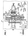
- FIG. 1there is shown a simplified diagrammatic view of a portion of a contact lens production system 10 including those material handling modules or processing stations designed to enable expedient and consolidated lens hydration and packaging processes.
- these stationsinclude: an automatic lens inspection station 15 for receiving a conveyance of transportable structures 12 comprising an array of lens mold cavities having a formed lens blank therein, inspecting the lenses for defects, and generating a pattern of those lenses determined as passing a level of inspection so that only "good" lenses, i.e., those lenses having passed a first level of lens inspection, are subsequently processed; a lens removal station 20 including mechanisms for removing those lenses determined to have failed the lens inspection process; a lens transfer mechanism 25 for transferring each of the lenses from the transportable structures into a lens hydration tray 27 structure in accordance with the pattern generated by lens inspection station for a subsequent hydration process; a hydration station 30 including a hydration tower 35 enabling the expedient hydration of cured lens blanks in their hydration
- the expedited and intelligent lens product handling and conveyanceis enabled under the programmed control and supervision of an enhanced programmable logic control system (PLC) or like equivalent control device 99 which includes a database comprising data records for tracking the locations of all possible lens fabrication transport structures and identifications.
- PLCprogrammable logic control system
- arrays of ophthalmic contact lenses formed in mold assembliesare first cured in a curing assembly and subject to a de-mold process whereby a back curve mold is removed from a front curve mold while leaving the lens situated in the front curve mold cavity (not shown).
- the lens front curve molds with formed lenses thereinare carried by lens fabrication structures such as trays or "pallets" 12 configured to transport an array of molds, e.g., a 2x4 array of lenses, for conveyance throughout the system.
- the transport structuremay itself comprise an integrated array of front curve mold structures.
- Figures 2(a)-2(b)comprise a flow diagram depicting the process 100 for enabling intelligent lens transfer and conveyance in the lens handling system of Figure 1.
- the processbegins by conveying the lens transport structure 12 which, for illustrative purposes, comprises a 2x4 pallet carrying an array lens mold structures and cured lens blanks therein, from a de-mold process (not shown) to the Automatic Lens Inspection station 15 where the lenses are coarsely analyzed in their front curve mold structure for defects such as rips or tears, darkspots, bubbles, impurities, and the like, according to conventional processes.
- inspection datacomprising the pass/fail status of individual cavities on the pallet is generated for inclusion in a data record associated with each pallet for tracking and control purposes.
- the pass/fail status of respective accepted/rejected lenses resulting from the lens inspectionis represented as a bit pattern, as will be explained in greater detail.
- each lens transport structure conveyed in the systemhas an associated electronic data record 13 that is communicated between the software control mechanisms of the PLC control system 99 at each successive material handling station as lens processing for that lens transport structure proceeds at the respective stations.
- the electronic data record 13 associated with the lens transport structure that is conveyed in the systemincludes information for identification and tracking including, but not limited to: a unique identifier for the lens transport structure (e.g., pallet) carrying the lens, a lot number, lot size, product code, lens parameter information including power, cylinder, axis and expiration date (as an example for toric lenses), process time, a pallet status code for identifying an empty pallet or one that has passed, and a station code including codes indicating: Passed FC/BC Transfer and Load, Passed Tween Stamp, Passed Filling, Passed Deposition, Passed Pre Cure, Passed Pre Heat and Cure, Passed Demold Pre Heat and Demold, Passed Inspection, Passed FC Transfer and Hydration, Hydration & Lens Transfer, and associated time stamp information at each station, etc.
- a unique identifier for the lens transport structuree.g., pallet
- lens parameter informationincluding power, cylinder, axis and expiration date (as
- the data recordfurther includes the inspection result data, particularly in the form of a binary word representing the pattern of accepted/rejected lenses resulting from the lens inspection.
- a respective byte 17including 8-bit positions corresponding to each of the lenses in the array, e.g., a 2x4 array for illustrative purposes.
- Each bit position of the byte 17will have a bit value generated at the time of lens inspection at the lens inspection station. These values include either of "1", for example, to indicate a good lens present at that lens position, or a bit value of "0", for example, to indicate a rejected lens at that bit position.
- the data conveyed for acceptable lenses at lens positions 1-4will be "00011110".
- the lenses indicated as being rejected for that palletare removed by the lens removal mechanism at the lens removal station 20.
- the transport structuresare then conveyed to the lens transfer assembly 25 at the hydration station where the remaining acceptable lenses are to be transferred to a hydration tray 27 registered to receive the transfer of acceptable lenses according to the bit pattern information.
- the lens position informationis logically communicated to hydration station via the PLC.
- the lens fabrication transport structures or pallets 12are conveyed serially in the direction indicated by an arrow "A".
- the hydration tray 27may accommodate an increased number of lenses, and for example, may comprise a 2x8 array of lens positions.
- These hydration trays 27are indexed along a direction B and registered at a location indicated by a hydration tray 26 in a manner so as to facilitate the transfer of lenses thereto from the transport pallets. That is, under PLC control at the lens transfer assembly 25, as depicted conceptually in Figure 3(b), lenses from lens positions 0-7 of transport structure 12b are simultaneously picked up and placed in corresponding positions 0-7 in hydration tray 27.
- a corresponding data record 23is logically formed as a result of lens transfer at the station 25 for subsequent conveyance in the system.
- This data record 23maintains the two bytes 17 indicating presence of "good" lenses at positions according to the respective bit values indicated from the data records 13 for the lenses conveyed by the corresponding two 2x4 transport structures e.g., 12a, 12b from Figure 3(a), with the first byte corresponding to positions 0-7 and the second byte corresponding to positions 8-15.
- the lensesare processed at the hydration station. Further details regarding the hydration process may be found in commonly-owned and issued U.S. Patent No. 6,207,086 and in commonly-owned, co-pending United States Patent Application No. 09/252,307, filed February 18, 1999, the contents and disclosure of each of which is incorporated by reference as if fully set forth herein.
- the lens transfer operation at lens transfer station 25includes a step of precisely operating a servo motor for aligning a mechanized lens transfer head 33 comprising a two lines of eight vacuum suction nozzles 34 each with the lens positions of the corresponding two 2x4 transport structures 12a, 12b, activating a negative pressure manifold for enabling lens pick up at the respective lens locations therefrom, and aligning and transferring the individual lenses to respective positions on the hydration tray 26.
- each tray 27 containing hydrated lensesis moved in the direction of arrow "C,” where they are lowered from the hydration tower by elevator mechanism 35 at a location 29 and conveyed in the direction of arrow "D" to a position 31 in registration with the lens unload station 55 where the hydrated lenses are to be intelligently transferred from the hydration tray to individual packages contained in the individually registered transport pucks.
- the lens transfer bit pattern included with the electronic data record for that tray hydration 27 at position 31is communicated to the intelligent puck transfer assembly 50 and lens load station 55 at step 118 so that the position of the good lenses remaining in the tray may be determined.
- the intelligent puck transfer assembly 50is actuated for staging zero or more pucks in the appropriate position for lens transfer from the hydration tray 27.
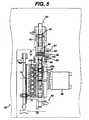
- Figure 5illustrates an example embodiment of the intelligent puck transfer and staging assembly 50 according to the principles of the invention.
- a conveyor belt or like transport mechanism 60conveys a series of pucks 52, each comprising a previously loaded lens package 53 for receiving a lens to be loaded from the hydration tray at the lens load station 55.
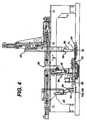
- the bit pattern information communicated from the hydration station associated with the hydration trayis utilized to register anywhere between 0 and 8 pucks at a lens load staging area 70 in the manner as follows: First, at the lens load station 55, as shown in Figure 4, a series of eight lens transfer nozzles 59 are utilized and individually activated to grab only the acceptable lenses from a respective row of the hydration tray 27. Referring back to Figure 3(b), at the hydration station, the tray 27 is organized as a first row 37a comprising zero or more good lenses at positions 4-7 and 12-15 and a second row 37b comprising lenses at positions 0-3 and 8-11.
- bit positions of the two bytes of information 17 maintained for that trayare communicated to the puck registration assembly 50 to enable the staging of individual pucks 52 for a subsequent lens transfer operation.
- transfer of good lenses from the hydration trayis successively performed on a row-by-row basis such that, as shown in Figure 3(b), good lenses at positions indicated in row 37a are first transferred and then good lenses at positions indicated in row 37b are transferred.
- the bit position values of the known good lensesare mapped into a new 8-bit byte 57 at the puck transfer assembly as shown in Figure 3(c).
- any of the 8-bit positions of puck staging byte 57 having a "1"are used by the puck transfer assembly 50 to enable registration of a puck 52 carrying an individual package into a corresponding position along the conveyor 90 of the lens load staging area 70. More specifically, as shown in the intelligent puck transfer assembly 50 of Figure 5, a servo-operated pin-wheel mechanism 80 comprising individual lugs 82 and a lug belt 90 comprising lugs 92 operating for indexed motion in a direction indicated by arrow "E " in conjunction with the pinwheel 80 cooperatively operate to stage zero or more pucks according to the pattern for the bit positions of each consecutive row 37a, 37b.
- the pinwheel and lug belt 90will index forward without a puck release.
- a lensis present at a position in the row 37a, i.e., the bit pattern indicates a "1" at a row position
- a puckis loaded to the pinwheel, engaged by the lug 82 of the pinwheel, and released by the pinwheel for registered movement along the lug belt 90.
- the lug belt 90may receive up to 8 pucks at a time for staging according to the row bit pattern from hydration. As shown in Figure 5, a puck 52a is shown released to the belt 90 in a position followed by two empty positions, indicating no lenses at the corresponding position in the hydration tray.
- a series of sensorsis utilized by the control system to ensure registered movement in accordance with the bit pattern associated with lenses to be loaded from the hydration tray.
- a first sensor 85is provided for ensuring that a puck is present at the pinwheel 80
- a second sensor 87is provided to ensure presence of a next puck so that the continuous indexing may be assured
- a third sensor 89is provided to ensure that the puck has actually been released and engaged by a lug 92 for movement along the belt 90.
- a rake mechanism 95under programmed control of an air cylinder 98 is activated to engage the lenses from the lug belt 90 and advance the lens pucks in their respective positions, in a direction indicated by an arrow "F" to the lens load position 71.
- step 125indicates the step of pushing the staged pucks to the load lens position 71 as described with respect to Figure 5.
- the puck staging sequence for the next row of lensese.g., row 37b in Figure 3(b) in the hydration tray is initiated.
- the lenses from the hydration tray corresponding to the row of pucks currently staged according to the transferred bit pattern for that roware picked and readied for transfer.
- a lens transfer assembly 63 including eight in-line suction nozzle assembly 59is extended, under servo-motor control, to the lens transfer position 31 at the hydration station 30 to pick up the lenses from the row of the hydration tray 37. Thereafter, the lens transfer assembly 63 is retracted back to the lens transfer station 55 to register each lens transfer nozzle carrying a lens with a corresponding puck staged at the load position 71 according to the bit pattern for that row. Extended and retracted movement of the lens transfer assembly 63 including nozzle assembly 59 is shown indicated by the direction of arrow "G".
- the lens transfer nozzles 59are actuated to physically transfer the lens to the corresponding staged puck in row 71.
- the lens transfer mechanismmay be found in EP-A-1029789 entitled CONTACT LENS TRANSFER AND MATERIAL REMOVAL SYSTEM (VTN-0418), the whole contents and disclosure of which is incorporated by reference as if fully set forth herein.
- the pucks having lens transferred theretoare pushed to an exit conveyor belt for subsequent processing at the next contact lens fabrication station, e.g., a lens detect station. That is, referring back to Figure 5, once the lenses have been loaded into a corresponding staged puck in lens transfer row 71, the puck including package and loaded lens is pushed by rake mechanism 95 in the direction indicated by an arrow "F' " to an exit conveyor mechanism 73 for carrying the pucks 52 including a lens package and a transferred hydrated lens.
- the rake mechanism 95is a dual-push assembly enabling simultaneous pushing of lenses staged by the lug belt 90 to the corresponding lens load position 71 while pushing pucks having packages loaded with lenses at the lens load station 71 to the exit conveyor 73.
- Figure 5shows a lens containing lens package carried by puck 52c having been pushed by rake 95 at a position for a previous hydration tray row. It is understood that the position of prior loaded package 52c corresponds to a first position indicating possibly that the bit pattern for the prior hydration tray row transferred was "00000001".
- the PLClogically tracks the pucks that have been transferred to the exit conveyor belt 73.
- the plurality of pucks that have been transferred for subsequent processing according to the lens bit positionsare tracked according to a 16 bit word 47 corresponding to the two rows of the hydration tray.
- the byte pattern corresponding to row 37a of the trayis mapped into bit positions 0-8 of the 16-bit word 47 while the byte pattern corresponding to row 37b of the tray is mapped into bit positions 8-15 of the 16-bit word 47.
- the16 bit wordis used to track the lens parameter, lot, status and other processing information for downstream lens fabrication processing/packaging.
- the intelligent lens transfer process as described with respect to Figures 2(a) - 2(b)is a repetitive process, with processing of successive lens fabrications pallets and rows of hydration trays in the manner described herein. It should be understood, that the intelligent lens transfer scheme as described herein is performed even when lot changes are seamlessly effected in the manner described in commonly-owned, co-pending U.S. Patent Application Serial No. 09/305,885 filed May 5, 1999.
- intelligent lens transfermay be at the back end after an inspection step, and not necessarily from a hydration tray to individual pallets for further processing, e.g., for operations such as applying a lens coating step or a step to add pigmentation to a lens, etc.
Landscapes
- Engineering & Computer Science (AREA)
- Mechanical Engineering (AREA)
- Physics & Mathematics (AREA)
- Manufacturing & Machinery (AREA)
- General Physics & Mathematics (AREA)
- Automation & Control Theory (AREA)
- Quality & Reliability (AREA)
- General Engineering & Computer Science (AREA)
- Business, Economics & Management (AREA)
- General Health & Medical Sciences (AREA)
- Tourism & Hospitality (AREA)
- Strategic Management (AREA)
- General Business, Economics & Management (AREA)
- Primary Health Care (AREA)
- Theoretical Computer Science (AREA)
- Marketing (AREA)
- Human Resources & Organizations (AREA)
- Economics (AREA)
- Health & Medical Sciences (AREA)
- Eyeglasses (AREA)
- General Factory Administration (AREA)
- Packaging Frangible Articles (AREA)
Description
Claims (22)
- A method for automatically transporting a plurality of products for sequentialprocessing at one or more processing stations, one processing station comprising amechanism for determining acceptability of individual products of said plurality ofproducts conveyed thereto on one or more first transport structures, wherein said one or more first transport structures do not carry individual packages said methodcomprising:a) generating an information record associated with each first transport structure carryinga plurality of products, said record including information for identifying products carriedby said first transport structure and including a data structure identifying locations of anyproduct on said transport structure determined to have met acceptability criteria asdetermined at said one processing station;b) conveying said first transport structure carrying zero or more acceptable products insequence to one or more downstream processing stations, and while at each processingstation accessing each information record and updating said associated information withstatus of products as a result of processing thereat;c) communicating an updated information record associated with a first transportstructure currently en route to a product unload area to a transport staging means forstaging a plurality of individual transport structures, wherein each of said individual transport structures carry a single lens package and is capable of receiving anindividual product to be transferred from said first transport structure, said staging meansresponsive to said data structure for aligning a plurality of individual transport structures in a staging area according to locations identified in said data structure as includingacceptable products; and,d) transferring zero or more acceptable products from identified locations in said firsttransport structure at said product unload area to said staging area and placing acorresponding individual product to an associated aligned individual transport structure,wherein said updated information record associated with a first transport structurecurrently en route to a product unload area is communicated prior to arrival of said firsttransport structure thereat.
- The method as claimed in Claim 1, wherein one of said processing stations is capableof processing acceptable products from one or more transport structures conveyedthereto, said method further comprising the steps of:whereby said step c) includes communicating an updated information record associatedwith a second transport structure currently en route to said transport staging area forstaging a plurality of individual transport structures wherein each of said individual transport structures carry a single lens package and is capable of receiving anindividual product to be transferred from said second transport structure and, step d) includes transferring zero or more acceptable products from identified locations insaid second transport structure and placing a corresponding individual product to anassociated aligned individual transport structure carrying a single lens package.transferring identified acceptable products from one or more first transport structures to asecond transport structure for simultaneously processing at said one of said processingstations, wherein said second transport structure does not carry individual lens packages; and,generating a further information record associated with said second transport structure atsaid processing station, including updating said data structure to identify known locationsof zero or more acceptable products on said second transport structure,
- The method as claimed in Claim 1, wherein said data structure comprises a bit patternincluding a pre-defined number of bits, each bit associated with a particular location onsaid transport structure and having a first value indicating location of acceptable productor, a second value indicating absence of an acceptable product.
- The method as claimed in Claim 1, wherein prior to transferring step b), the step ofremoving zero or more products from said first transport structure identified at saidinspection station as failing to meet said acceptable criteria in accordance with said datastructure.
- The method as claimed in Claim 2, wherein said product is an ophthalmic lens, saidfirst transport structures for transferring formed lens products comprising a fabricationtray.
- The method as claimed in Claim 2, wherein said step of transferring identifiedacceptable products from one or more first transport structures to a second transportstructure includes mapping the location of each zero or more acceptable product locationstransferred from each respective one or more transport structures providing product to thesecond transport structure into said data structure.
- The method as claimed in Claim 6, wherein said step b) of transferring one or morepluralities of products from said one or more transport structures to a second transportstructure includes buffering a plurality of first transport structures at a buffer locationprior to said transfer.
- The method as claimed in Claim 5, wherein said product is an ophthalmic lens, saidsecond transport structure comprising a hydration tray means for carrying acceptable lensproducts from one or more first transport structures to a hydration station forsimultaneously hydrating said formed lenses.
- The method as claimed in Claim 3, wherein said step of staging a plurality ofindividual transport structures each capable of receiving an individual product to betransferred from said first transport structure comprises the steps of:feeding a plurality of individual transport structures to a first location via a first conveyorin accordance with said received bit pattern;transporting zero or more individual transport structures to said staging area via a secondconveyor in accordance with a received bit pattern;one of engaging an individual transport structure in response to detection of a first bitvalue from said bit pattern, or preventing engagement of an individual transport structurein response to detection of a second bit value from said bit pattern; and respectively inresponse,handing-off an engaged individual transport structure to a second conveyor for indexedconveyance to said staging area in accordance with a first bit value of said bit pattern oris prevented from handing-off said individual transport structure to said second conveyorin accordance with a second bit value of said bit pattern; and,enabling indexed movement of said second conveyor in accordance with an amount ofsaid pre-defined number of bits in said bit pattern, whereby handed-off individual transport structures are conveyed to said staging area and registered at locationscorresponding to received first bit values of said pre-defined number of bits.
- The method as claimed in Claim 9, wherein said staging area includes a product loadposition where said acceptable products are simultaneously transferred thereto from aproduct unload location, said method further comprising the step of simultaneouslypushing said individual transport structures to said product load position after registeredin accordance with said bit pattern.
- A system for automatically transporting a plurality of ophthalmic lens for sequentialprocessing at one or more processing stations, one processing station comprising amechanism for determining acceptability of individual products of said plurality ofproducts conveyed thereto on one or more first transport structures, wherein said one or more first transport structures do not carry individual package and generating aninformation record associated with each first transport structure including information foridentifying products carried by said first transport structure and including a data structureidentifying locations of any product on said first transport structure determined to havemet acceptability criteria as determined at said one processing station, said systemcomprising:communications infrastructure for enabling access to said information records at eachdownstream processing station in coordination with processing of products carried by itsassociated first transport structure at a respective processing station;a transport staging means for staging a plurality of individual transport structures wherein each of said individual transport structures carry a single lens package and iscapable of receiving an individual product to be transferred from said first transportstructure in response to a received information record associated with a first transportstructure currently en route to a product unload area, said staging means including means for aligning zero or more individual transport structures in a staging area according tolocations identified in said data structure as including acceptable products; and,a first transfer mechanism including transfer elements for transferring zero or moreacceptable products from said first transport structure to respective individual alignedtransport structures in said staging area; and,control means responsive to receipt of said information records associated with one ormore first transport structures for coordinating activation of said transfer elements atlocations of acceptable products to be transferred by said first transfer mechanism asindicated by said data structure, and initiating simultaneous transfer and placement ofindividual products to a respective aligned transport structure, wherein said informationrecord associated with a first transport structure currently en route to a product unloadarea is communicated prior to arrival of said first transport structure thereat.
- The system for automatically transporting products as claimed in Claim 11, whereinone of said processing stations is capable of processing acceptable products from one ormore first transport structures conveyed thereto, said system further comprising:second transfer mechanism for transferring identified acceptable products from one ormore first transport structures to a second transport structure for simultaneouslyprocessing at said one of said processing stations, wherein said second transport structure does not carry individual lens packages and said control means responsive toreceipt of said information records associated with each respective one or more firsttransport structures for coordinating activation of said transfer elements at locations ofacceptable products to be transferred by said second transfer mechanism as indicated byrespective data structures for each first transport structure.
- The system for automatically transporting products as claimed in Claim 12, furthercomprising:whereby said communications infrastructure enables communication of an updatedinformation record associated with a second transport structure currently en route to saidtransport staging area for staging a plurality of individual transport structures, wherein each of said individual transport structures carry a single lens package and iscapable of receiving an individual product to be transferred from said second transportstructure.means for generating a further information record associated with said second transportstructure at said one of said processing stations, said record including an updated datastructure to identify known locations of zero or more acceptable lenses on said secondtransport structure,
- The system for automatically transporting products as claimed in Claim 11, whereinsaid data structure comprises a bit pattern including a pre-defined number of bits, each bitassociated with a particular location on said transport structure and having a first valueindicating location of acceptable product or, a second value indicating absence of anacceptable product.
- The system for automatically transporting products as claimed in Claim 11, furtherincluding a mechanism for removing zero or more products from said first transportstructure identified as failing to meet said acceptable criteria in accordance with said datastructure.
- The system for automatically transporting products as claimed in Claim 12, whereinsaid product is an ophthalmic lens, said first transport structures for transporting formedlens products comprising a fabrication tray.
- The system for automatically transporting products as claimed in Claim 16, whereinsaid product is an ophthalmic lens, said second transport structure comprising a hydrationtray means for carrying acceptable lens products from one or more first transportstructures to a hydration station for hydrating said formed lenses.
- The system for automatically transporting products as claimed in Claim 13, whereinsaid means for generating a further information record associated with said secondtransport structure at said one of said processing stations includes mechanism formapping the location of each zero or more acceptable product locations transferred fromeach respective one or more transport structures providing product to the second transportstructure into said data structure.
- The system for automatically transporting products as claimed in Claim 14, whereinsaid staging mechanism includes:said control means enabling indexed movement of said second conveyor in accordancewith an amount of said pre-defined number of bits in said bit pattern, whereby handed-offindividual transport structures are conveyed to said staging area at a locationcorresponding to received first bit values of said pre-defined number of bits.a first conveyor mechanism for feeding a plurality of individual transport structures to afirst location in accordance with said received bit pattern;a second conveyor mechanism for transporting zero or more individual transportstructures to said staging area in accordance with a received bit pattern;device located at said first location for engaging an individual transport structure inresponse to detection of a first bit value from said bit pattern, or preventing engagementof an individual transport structure in response to detection of a second bit value fromsaid bit pattern, said device either handing-off an engaged individual transport structureto said second conveyor for indexed conveyance to said staging area in accordance with afirst bit value of said bit pattern or is prevented from handing-off said individual transport structure to said second conveyor in accordance with a second bit value of said bitpattern;
- The system for automatically transporting products as claimed in Claim 19, whereinsaid staging area includes a product load position where said acceptable products aresimultaneously transferred thereto by said first transfer mechanism, said stagingmechanism further comprising pusher mechanism for pushing said individual transportstructures to said product load position according to said bit pattern.
- The system for automatically transporting products as claimed in Claim 20, furthercomprising an exit conveyor for transporting said individual transport structuresincluding a product transferred thereto, said pusher mechanism simultaneously pushingeach said individual transport structure including a product from said product loadposition to said exit conveyor.
- A program storage device readable by a machine, tangibly embodying a program ofinstructions executable by the machine to perform method steps for automaticallytransporting a plurality of products for sequential processing at one or more processingstations, one processing station comprising a mechanism for determining acceptability ofindividual products of said plurality of products conveyed thereto on one or more firsttransport structures, wherein said one or more first transport structures do not carry individual packages, said method steps comprising:a) generating an information record associated with each first transport structure carryinga plurality of products, said record including information for identifying products carriedby said first transport structure and including a data structure identifying locations of anyproduct on said transport structure determined to have met acceptability criteria asdetermined at said one processing station;b) conveying said first transport structure carrying zero or more acceptable products insequence to one or more downstream processing stations, and while at each processingstation accessing each information record and updating said associated information withstatus of products as a result of processing thereat;c) communicating an updated information record associated with a first transportstructure currently en route to a product unload area to a transport staging means forstaging a plurality of individual transport structures wherein each of said individual transport structures carry a single lens package and is capable of receiving anindividual product to be transferred from said first transport structure, said staging meansresponsive to said data structure for aligning a plurality of individual transport structuresin a staging area according to locations identified in said data structure as includingacceptable products; and,d) transferring zero or more acceptable products from identified locations in said firsttransport structure at said product unload area to said staging area and placing acorresponding individual product to an associated aligned individual transport structure,wherein said updated information record associated with a first transport structurecurrently en route to a product unload area is communicated prior to arrival of said firsttransport structure thereat.
Applications Claiming Priority (2)
| Application Number | Priority Date | Filing Date | Title |
|---|---|---|---|
| US925389 | 2001-08-09 | ||
| US09/925,389US6836692B2 (en) | 2001-08-09 | 2001-08-09 | System and method for intelligent lens transfer |
Publications (3)
| Publication Number | Publication Date |
|---|---|
| EP1288758A2 EP1288758A2 (en) | 2003-03-05 |
| EP1288758A3 EP1288758A3 (en) | 2003-07-23 |
| EP1288758B1true EP1288758B1 (en) | 2005-10-12 |
Family
ID=25451672
Family Applications (1)
| Application Number | Title | Priority Date | Filing Date |
|---|---|---|---|
| EP02255597AExpired - LifetimeEP1288758B1 (en) | 2001-08-09 | 2002-08-09 | System and method for intelligent lens transfer |
Country Status (12)
| Country | Link |
|---|---|
| US (1) | US6836692B2 (en) |
| EP (1) | EP1288758B1 (en) |
| JP (1) | JP2003202915A (en) |
| KR (1) | KR20030014650A (en) |
| CN (1) | CN1299176C (en) |
| AR (1) | AR035093A1 (en) |
| AU (1) | AU2002300417B2 (en) |
| BR (1) | BRPI0203165B1 (en) |
| CA (1) | CA2396999C (en) |
| DE (1) | DE60206576T2 (en) |
| SG (1) | SG95700A1 (en) |
| TW (1) | TW591355B (en) |
Cited By (10)
| Publication number | Priority date | Publication date | Assignee | Title |
|---|---|---|---|---|
| CN102530506A (en)* | 2010-12-08 | 2012-07-04 | 英业达股份有限公司 | Production line machine table of notebook computer |
| US8973736B2 (en) | 2011-11-07 | 2015-03-10 | Beckman Coulter, Inc. | Magnetic damping for specimen transport system |
| US9046506B2 (en) | 2011-11-07 | 2015-06-02 | Beckman Coulter, Inc. | Specimen container detection |
| US9248982B2 (en) | 2011-05-13 | 2016-02-02 | Beckman Coulter, Inc. | System and method including laboratory product transport element |
| US9446418B2 (en) | 2011-11-07 | 2016-09-20 | Beckman Coulter, Inc. | Robotic arm |
| US9459273B2 (en) | 2011-05-13 | 2016-10-04 | Beckman Coulter, Inc. | Laboratory product transport element and path arrangement |
| US9482684B2 (en) | 2011-11-07 | 2016-11-01 | Beckman Coulter, Inc. | Centrifuge system and workflow |
| US9506943B2 (en) | 2011-11-07 | 2016-11-29 | Beckman Coulter, Inc. | Aliquotter system and workflow |
| US9588038B2 (en) | 2012-09-14 | 2017-03-07 | Beckman Coulter, Inc. | Analytical system with capillary transport |
| US9910054B2 (en) | 2011-11-07 | 2018-03-06 | Beckman Coulter, Inc. | System and method for processing samples |
Families Citing this family (33)
| Publication number | Priority date | Publication date | Assignee | Title |
|---|---|---|---|---|
| AU2003221328A1 (en)* | 2002-03-07 | 2003-09-16 | Yamaha Motor Co., Ltd. | Electronic part inspection device |
| US20070005180A1 (en)* | 2002-03-13 | 2007-01-04 | Stingel Frederick J Iii | Automated container storage and delivery system |
| GB0329718D0 (en)* | 2003-12-22 | 2004-01-28 | Bausch & Lomb | Contact lens manufacture |
| US7735726B2 (en)* | 2005-11-17 | 2010-06-15 | Target Brands, Inc. | Voucher system and method of use |
| DE102006022192B4 (en)* | 2006-05-12 | 2009-08-27 | Rovema - Verpackungsmaschinen Gmbh | Device for welding a film web |
| US20090223592A1 (en) | 2008-03-04 | 2009-09-10 | Vanrx Pharmaceuticals, Inc. | Robotic filling systems and methods |
| US12164465B2 (en) | 2008-03-04 | 2024-12-10 | Vanrx Pharmasystems Inc. | Robotic filling systems and methods |
| US9789986B2 (en)* | 2009-02-26 | 2017-10-17 | Vanrx Pharmasystems Inc. | Robotic filling systems and methods |
| JP2010052938A (en)* | 2008-08-29 | 2010-03-11 | Ihi Corp | Conveyance control device and conveyance control method |
| DE102009012558A1 (en)* | 2009-03-10 | 2010-09-23 | Wipotec Wiege- Und Positioniersysteme Gmbh | Control device for a production machine |
| HUE033724T2 (en)* | 2010-12-16 | 2017-12-28 | Novartis Ag | Method and apparatus for transferring contact lenses between two consecutive processing stations being operated with different cycle speeds |
| DE202012011690U1 (en) | 2012-03-09 | 2013-03-13 | Schneider Gmbh & Co. Kg | Plant for processing optical lenses |
| CN103587759B (en)* | 2012-08-15 | 2015-08-12 | 常熟晶悦半导体设备有限公司 | Eyeglass transmission package is installed |
| CN103611688B (en)* | 2013-10-28 | 2016-05-11 | 临海市锦铮机械有限公司 | Eyeglass automatic sorting machines |
| CN103736672B (en)* | 2013-12-31 | 2019-01-08 | 江苏大学 | A kind of eyeglass is classified sorting equipment online |
| CN104923492B (en)* | 2015-06-11 | 2017-11-17 | 江苏大学 | Contactless lens defects sorting equipment |
| DE102015015040A1 (en)* | 2015-11-12 | 2017-05-18 | Schneider Gmbh & Co. Kg | Method, installation and system for processing optical lenses |
| CN105629517B (en)* | 2016-02-16 | 2018-09-18 | 来明工业(厦门)有限公司 | Intelligent plastic spectacles production line |
| DE102016007837A1 (en) | 2016-05-25 | 2017-11-30 | Schneider Gmbh & Co. Kg | Method and system for processing optical lenses |
| DE102017001680A1 (en)* | 2017-02-22 | 2018-08-23 | Schneider Gmbh & Co. Kg | Plant and method for processing optical lenses |
| CN107537790B (en)* | 2017-10-10 | 2019-11-26 | 中山市光维智能科技有限公司 | Full-automatic circle detecting and classifying storage device for optical lenses |
| CN108674751A (en)* | 2018-03-06 | 2018-10-19 | 温州职业技术学院 | A kind of method of button cell detection packaging |
| CN109600782B (en)* | 2019-01-04 | 2021-09-07 | 四川虹美智能科技有限公司 | WiFi product, method and system for detecting WiFi product in flow production line |
| CN109677897A (en)* | 2019-03-01 | 2019-04-26 | 江苏汇鼎光学眼镜有限公司 | A kind of double-station eyeglass stiffened, drying halfpace transfer device |
| DE102019127664A1 (en) | 2019-10-15 | 2021-04-15 | INTRAVIS Gesellschaft für Lieferungen und Leistungen von bildgebenden und bildverarbeitenden Anlagen und Verfahren mbH | Method and arrangement for filling plastic parts |
| CN111580487A (en)* | 2020-05-30 | 2020-08-25 | 宁波伟立机器人科技股份有限公司 | Intelligent monitoring control system for industrial production line |
| US12116155B2 (en)* | 2021-04-12 | 2024-10-15 | Sojo Industries, Inc. | Mobile automated modular variety and multi pack production line system and method |
| CN113120287B (en)* | 2021-05-12 | 2023-01-31 | 贵州省种畜禽种质测定中心 | Egg sorting and packaging device and packaging method thereof |
| CN113277180B (en)* | 2021-05-26 | 2023-03-21 | 上海东富龙科技股份有限公司 | Working method of device for controlling bottle inversion in snakelike mesh belt conveying process |
| CN113977337B (en)* | 2021-12-28 | 2022-03-22 | 广州市腾嘉自动化仪表有限公司 | Material control system based on automatic production line |
| CN114476600B (en)* | 2022-03-09 | 2023-08-11 | 青岛融合光电科技有限公司 | Carrier glass alignment device with breakage sensing function and alignment method |
| CN115092437B (en)* | 2022-07-25 | 2024-08-23 | 水羊化妆品制造有限公司 | Discharging and boxing device and boxing equipment |
| DE102023123455B3 (en) | 2023-08-31 | 2025-01-16 | Singulus Technologies Aktiengesellschaft | System module for collecting and removing rejects |
Family Cites Families (40)
| Publication number | Priority date | Publication date | Assignee | Title |
|---|---|---|---|---|
| US4495313A (en)* | 1981-04-30 | 1985-01-22 | Mia Lens Production A/S | Preparation of hydrogel for soft contact lens with water displaceable boric acid ester |
| US4640489A (en)* | 1981-04-30 | 1987-02-03 | Mia-Lens Production A/S | Mold for making contact lenses, either the male or female mold sections being relatively more flexible |
| US4680336A (en)* | 1984-11-21 | 1987-07-14 | Vistakon, Inc. | Method of forming shaped hydrogel articles |
| GB8508247D0 (en)* | 1985-03-29 | 1985-05-09 | Sola Int Holdings | Contact lenses |
| JPS6299065A (en)* | 1985-10-22 | 1987-05-08 | Matsushita Electric Ind Co Ltd | Spherical grinding device |
| JPS62208438A (en)* | 1986-03-07 | 1987-09-12 | Canon Inc | Optical system drive device |
| US4909776A (en)* | 1987-08-28 | 1990-03-20 | Aisin Aw Co., Ltd. | Continuously variable transmission |
| US4782946A (en)* | 1987-09-17 | 1988-11-08 | Allergan, Inc. | Soft contact lens hydration device and kit |
| US4961820A (en)* | 1988-06-09 | 1990-10-09 | Fujitsu Limited | Ashing method for removing an organic film on a substance of a semiconductor device under fabrication |
| JP2654816B2 (en)* | 1988-11-18 | 1997-09-17 | 株式会社エヌテック | Lens transport table of lens processing machine |
| US4889664A (en)* | 1988-11-25 | 1989-12-26 | Vistakon, Inc. | Method of forming shaped hydrogel articles including contact lenses |
| US5039459A (en)* | 1988-11-25 | 1991-08-13 | Johnson & Johnson Vision Products, Inc. | Method of forming shaped hydrogel articles including contact lenses |
| US5094609A (en)* | 1990-04-17 | 1992-03-10 | Vistakon, Inc. | Chamber for hydrating contact lenses |
| US5080839A (en) | 1990-04-17 | 1992-01-14 | Johnson & Johnson Vision Products, Inc. | Process for hydrating soft contact lenses |
| US5690868A (en)* | 1993-01-19 | 1997-11-25 | The United States Of America As Represented By The Secretary Of The Army | Multi-layer high energy propellants |
| IL108992A (en)* | 1993-03-29 | 1997-11-20 | Johnson & Johnson Vision Prod | Solution removal nozzle |
| DE4323106A1 (en)* | 1993-07-10 | 1995-01-12 | Baumgarten Heinrich Kg | Handle attachment to a dish, for example a cookware |
| US5457140A (en)* | 1993-07-22 | 1995-10-10 | Johnson & Johnson Vision Products, Inc. | Method of forming shaped hydrogel articles including contact lenses using inert, displaceable diluents |
| US5568715A (en)* | 1994-05-31 | 1996-10-29 | Johnson & Johnson Vision Products, Inc. | Automated inspection system with transport and ejector conveyor |
| US5578331A (en)* | 1994-06-10 | 1996-11-26 | Vision Products, Inc. | Automated apparatus for preparing contact lenses for inspection and packaging |
| US5626000A (en)* | 1994-06-10 | 1997-05-06 | Johnson & Johnson Vision Products, Inc. | Packaging arrangement |
| US5555504A (en) | 1994-06-10 | 1996-09-10 | Johnson & Johnson Vision Products, Inc. | Production line tracking and quality control system |
| US5696686A (en)* | 1994-06-10 | 1997-12-09 | Johnson & Johnson Vision Products, Inc. | Computer system for quality control correlations |
| US5649410A (en)* | 1994-06-10 | 1997-07-22 | Johnson & Johnson Vision Products, Inc. | Post-hydration method and apparatus for transporting, inspecting and packaging contact lenses |
| US5461570A (en)* | 1994-06-10 | 1995-10-24 | Johnson & Johnson Vision Products, Inc. | Computer system for quality control correlations |
| US5528878A (en)* | 1994-06-10 | 1996-06-25 | Johnson & Johnson Vision Products, Inc. | Automated apparatus and method for consolidating products for packaging |
| US5836323A (en)* | 1994-06-10 | 1998-11-17 | Johnson & Johnson Vision Products, Inc. | Automated method and apparatus for hydrating soft contact lenses |
| US5640980A (en)* | 1994-06-10 | 1997-06-24 | Johnson & Johnson Vision Products, Inc. | Automated apparatus for hydrating soft contact lenses |
| US5607642A (en) | 1994-06-10 | 1997-03-04 | Johnson & Johnson Vision Products, Inc. | Interactive control system for packaging control of contact lenses |
| US5476111A (en)* | 1994-06-10 | 1995-12-19 | Johnson & Johnson Vision Products, Inc. | Apparatus for hydrating soft contact lenses |
| US5706634A (en)* | 1994-06-10 | 1998-01-13 | Johnson & Johnson Vision Products, Inc. | Contact lens transfer device |
| US5850107A (en)* | 1994-06-10 | 1998-12-15 | Johnson & Johnson Vision Products, Inc. | Mold separation method and apparatus |
| US5561970A (en)* | 1995-06-21 | 1996-10-08 | Johnson & Johnson Vision Products, Inc. | Automated robotic lens load system |
| US5807642A (en)* | 1995-11-20 | 1998-09-15 | Xue; Liang An | Solid oxide fuel cell stacks with barium and strontium ceramic bodies |
| JPH1039906A (en)* | 1996-05-10 | 1998-02-13 | Canon Inc | Line control method and apparatus and line system |
| CN1075439C (en) | 1997-03-25 | 2001-11-28 | 诺瓦提斯公司 | Molding processes |
| US6446017B1 (en)* | 1997-08-21 | 2002-09-03 | Micron Technology, Inc. | Method and system for tracking manufacturing data for integrated circuit parts |
| US6207086B1 (en)* | 1999-02-18 | 2001-03-27 | Johnson & Johnson Vision Care, Inc. | Method and apparatus for washing or hydration of ophthalmic devices |
| US6609041B1 (en)* | 1999-05-05 | 2003-08-19 | Johnson & Johnson Vision Care, Inc. | Method and system for SKU tracking and changeover |
| US6341726B1 (en)* | 1999-06-23 | 2002-01-29 | International Business Machines Corporation | Apparatus for inspecting elements on transport device |
- 2001
- 2001-08-09USUS09/925,389patent/US6836692B2/ennot_activeExpired - Lifetime
- 2002
- 2002-08-05AUAU2002300417Apatent/AU2002300417B2/ennot_activeCeased
- 2002-08-07CACA2396999Apatent/CA2396999C/ennot_activeExpired - Fee Related
- 2002-08-08TWTW091117829Apatent/TW591355B/ennot_activeIP Right Cessation
- 2002-08-08SGSG200204835Apatent/SG95700A1/enunknown
- 2002-08-08JPJP2002231861Apatent/JP2003202915A/enactivePending
- 2002-08-08ARARP020103006Apatent/AR035093A1/enactiveIP Right Grant
- 2002-08-08KRKR1020020046791Apatent/KR20030014650A/ennot_activeCeased
- 2002-08-09CNCNB021437599Apatent/CN1299176C/ennot_activeExpired - Fee Related
- 2002-08-09EPEP02255597Apatent/EP1288758B1/ennot_activeExpired - Lifetime
- 2002-08-09DEDE60206576Tpatent/DE60206576T2/ennot_activeExpired - Lifetime
- 2002-08-09BRBRPI0203165-5Apatent/BRPI0203165B1/ennot_activeIP Right Cessation
Cited By (15)
| Publication number | Priority date | Publication date | Assignee | Title |
|---|---|---|---|---|
| CN102530506B (en)* | 2010-12-08 | 2014-04-23 | 英业达股份有限公司 | Laptop Production Line Machines |
| CN102530506A (en)* | 2010-12-08 | 2012-07-04 | 英业达股份有限公司 | Production line machine table of notebook computer |
| US9459273B2 (en) | 2011-05-13 | 2016-10-04 | Beckman Coulter, Inc. | Laboratory product transport element and path arrangement |
| US10473676B2 (en) | 2011-05-13 | 2019-11-12 | Beckman Coulter, Inc. | Laboratory product transport element and path arrangement |
| US9248982B2 (en) | 2011-05-13 | 2016-02-02 | Beckman Coulter, Inc. | System and method including laboratory product transport element |
| US9658239B2 (en) | 2011-05-13 | 2017-05-23 | Beckman Coulter, Inc. | Laboratory product transport element and path arrangement |
| US9046506B2 (en) | 2011-11-07 | 2015-06-02 | Beckman Coulter, Inc. | Specimen container detection |
| US9482684B2 (en) | 2011-11-07 | 2016-11-01 | Beckman Coulter, Inc. | Centrifuge system and workflow |
| US9506943B2 (en) | 2011-11-07 | 2016-11-29 | Beckman Coulter, Inc. | Aliquotter system and workflow |
| US9446418B2 (en) | 2011-11-07 | 2016-09-20 | Beckman Coulter, Inc. | Robotic arm |
| US9910054B2 (en) | 2011-11-07 | 2018-03-06 | Beckman Coulter, Inc. | System and method for processing samples |
| US10048284B2 (en) | 2011-11-07 | 2018-08-14 | Beckman Coulter, Inc. | Sample container cap with centrifugation status indicator device |
| US10274505B2 (en) | 2011-11-07 | 2019-04-30 | Beckman Coulter, Inc. | Robotic arm |
| US8973736B2 (en) | 2011-11-07 | 2015-03-10 | Beckman Coulter, Inc. | Magnetic damping for specimen transport system |
| US9588038B2 (en) | 2012-09-14 | 2017-03-07 | Beckman Coulter, Inc. | Analytical system with capillary transport |
Also Published As
| Publication number | Publication date |
|---|---|
| DE60206576T2 (en) | 2006-07-13 |
| JP2003202915A (en) | 2003-07-18 |
| BR0203165A (en) | 2003-05-27 |
| DE60206576D1 (en) | 2005-11-17 |
| SG95700A1 (en) | 2003-04-23 |
| AU2002300417B2 (en) | 2008-06-05 |
| CN1299176C (en) | 2007-02-07 |
| BRPI0203165B1 (en) | 2015-08-04 |
| CN1406844A (en) | 2003-04-02 |
| TW591355B (en) | 2004-06-11 |
| CA2396999C (en) | 2010-10-12 |
| EP1288758A3 (en) | 2003-07-23 |
| US6836692B2 (en) | 2004-12-28 |
| CA2396999A1 (en) | 2003-02-09 |
| EP1288758A2 (en) | 2003-03-05 |
| US20030031540A1 (en) | 2003-02-13 |
| KR20030014650A (en) | 2003-02-19 |
| AR035093A1 (en) | 2004-04-14 |
Similar Documents
| Publication | Publication Date | Title |
|---|---|---|
| EP1288758B1 (en) | System and method for intelligent lens transfer | |
| EP0686898B1 (en) | Interactive control system for packaging control | |
| CA2179480C (en) | Automated robotic lens load system | |
| US8406917B2 (en) | System and method for random mixed palletizing of products | |
| AU720090B2 (en) | Automated consolidation station | |
| US5555504A (en) | Production line tracking and quality control system | |
| US5528878A (en) | Automated apparatus and method for consolidating products for packaging | |
| US5829222A (en) | Automated apparatus and method for consolidating products for packaging | |
| US20150336339A1 (en) | Method and Apparatus For Transferring Objects Between Two Consecutive Processing Stations Being Operated With Different Cycle Speeds | |
| HK1051906A (en) | System and method for intelligent lens transfer | |
| CA2519244C (en) | Interactive control system for packaging control | |
| JP2780052B2 (en) | Automatic packaging method | |
| CN111284999B (en) | Conveying system for automatically sorting tires | |
| CN118928941A (en) | Quality monitoring system for intelligent toothpaste production | |
| JPH11292034A (en) | Method for inspecting plastic injection molded product | |
| HK1032556B (en) | Method and system for sku tracking, and a method of tracking a plurality of molding devices | |
| HK1032556A1 (en) | Method and system for sku tracking, and a method of tracking a plurality of molding devices | |
| CN1894639A (en) | Contact lens manufacture |
Legal Events
| Date | Code | Title | Description |
|---|---|---|---|
| PUAI | Public reference made under article 153(3) epc to a published international application that has entered the european phase | Free format text:ORIGINAL CODE: 0009012 | |
| AK | Designated contracting states | Kind code of ref document:A2 Designated state(s):AT BE BG CH CY CZ DE DK EE ES FI FR GB GR IE IT LI LU MC NL PT SE SK TR Designated state(s):AT BE BG CH CY CZ DE DK EE ES FI FR GB GR IE IT LI LU MC NL PT SE SK TR | |
| AX | Request for extension of the european patent | Extension state:AL LT LV MK RO SI | |
| PUAL | Search report despatched | Free format text:ORIGINAL CODE: 0009013 | |
| AK | Designated contracting states | Designated state(s):AT BE BG CH CY CZ DE DK EE ES FI FR GB GR IE IT LI LU MC NL PT SE SK TR | |
| AX | Request for extension of the european patent | Extension state:AL LT LV MK RO SI | |
| 17P | Request for examination filed | Effective date:20040120 | |
| AKX | Designation fees paid | Designated state(s):DE FR GB IE IT | |
| 17Q | First examination report despatched | Effective date:20040304 | |
| GRAP | Despatch of communication of intention to grant a patent | Free format text:ORIGINAL CODE: EPIDOSNIGR1 | |
| GRAS | Grant fee paid | Free format text:ORIGINAL CODE: EPIDOSNIGR3 | |
| GRAA | (expected) grant | Free format text:ORIGINAL CODE: 0009210 | |
| AK | Designated contracting states | Kind code of ref document:B1 Designated state(s):DE FR GB IE IT | |
| REG | Reference to a national code | Ref country code:GB Ref legal event code:FG4D | |
| REG | Reference to a national code | Ref country code:IE Ref legal event code:FG4D | |
| REF | Corresponds to: | Ref document number:60206576 Country of ref document:DE Date of ref document:20051117 Kind code of ref document:P | |
| ET | Fr: translation filed | ||
| PLBE | No opposition filed within time limit | Free format text:ORIGINAL CODE: 0009261 | |
| STAA | Information on the status of an ep patent application or granted ep patent | Free format text:STATUS: NO OPPOSITION FILED WITHIN TIME LIMIT | |
| 26N | No opposition filed | Effective date:20060713 | |
| REG | Reference to a national code | Ref country code:HK Ref legal event code:WD Ref document number:1051906 Country of ref document:HK | |
| REG | Reference to a national code | Ref country code:FR Ref legal event code:PLFP Year of fee payment:15 | |
| REG | Reference to a national code | Ref country code:FR Ref legal event code:PLFP Year of fee payment:16 | |
| REG | Reference to a national code | Ref country code:FR Ref legal event code:PLFP Year of fee payment:17 | |
| PGFP | Annual fee paid to national office [announced via postgrant information from national office to epo] | Ref country code:IT Payment date:20190821 Year of fee payment:18 | |
| PGFP | Annual fee paid to national office [announced via postgrant information from national office to epo] | Ref country code:FR Payment date:20210714 Year of fee payment:20 Ref country code:IE Payment date:20210810 Year of fee payment:20 | |
| PGFP | Annual fee paid to national office [announced via postgrant information from national office to epo] | Ref country code:DE Payment date:20210630 Year of fee payment:20 Ref country code:GB Payment date:20210701 Year of fee payment:20 | |
| PG25 | Lapsed in a contracting state [announced via postgrant information from national office to epo] | Ref country code:IT Free format text:LAPSE BECAUSE OF NON-PAYMENT OF DUE FEES Effective date:20200809 | |
| REG | Reference to a national code | Ref country code:DE Ref legal event code:R071 Ref document number:60206576 Country of ref document:DE | |
| REG | Reference to a national code | Ref country code:GB Ref legal event code:PE20 Expiry date:20220808 | |
| REG | Reference to a national code | Ref country code:IE Ref legal event code:MK9A | |
| PG25 | Lapsed in a contracting state [announced via postgrant information from national office to epo] | Ref country code:IE Free format text:LAPSE BECAUSE OF EXPIRATION OF PROTECTION Effective date:20220809 Ref country code:GB Free format text:LAPSE BECAUSE OF EXPIRATION OF PROTECTION Effective date:20220808 |