EP1288654B1 - Biosensor - Google Patents
BiosensorDownload PDFInfo
- Publication number
- EP1288654B1 EP1288654B1EP02774074AEP02774074AEP1288654B1EP 1288654 B1EP1288654 B1EP 1288654B1EP 02774074 AEP02774074 AEP 02774074AEP 02774074 AEP02774074 AEP 02774074AEP 1288654 B1EP1288654 B1EP 1288654B1
- Authority
- EP
- European Patent Office
- Prior art keywords
- electrode
- counter electrode
- working electrode
- branches
- sample
- Prior art date
- Legal status (The legal status is an assumption and is not a legal conclusion. Google has not performed a legal analysis and makes no representation as to the accuracy of the status listed.)
- Expired - Lifetime
Links
Images


Classifications
- C—CHEMISTRY; METALLURGY
- C12—BIOCHEMISTRY; BEER; SPIRITS; WINE; VINEGAR; MICROBIOLOGY; ENZYMOLOGY; MUTATION OR GENETIC ENGINEERING
- C12Q—MEASURING OR TESTING PROCESSES INVOLVING ENZYMES, NUCLEIC ACIDS OR MICROORGANISMS; COMPOSITIONS OR TEST PAPERS THEREFOR; PROCESSES OF PREPARING SUCH COMPOSITIONS; CONDITION-RESPONSIVE CONTROL IN MICROBIOLOGICAL OR ENZYMOLOGICAL PROCESSES
- C12Q1/00—Measuring or testing processes involving enzymes, nucleic acids or microorganisms; Compositions therefor; Processes of preparing such compositions
- C12Q1/001—Enzyme electrodes
- C12Q1/005—Enzyme electrodes involving specific analytes or enzymes
- C12Q1/006—Enzyme electrodes involving specific analytes or enzymes for glucose
- C—CHEMISTRY; METALLURGY
- C12—BIOCHEMISTRY; BEER; SPIRITS; WINE; VINEGAR; MICROBIOLOGY; ENZYMOLOGY; MUTATION OR GENETIC ENGINEERING
- C12Q—MEASURING OR TESTING PROCESSES INVOLVING ENZYMES, NUCLEIC ACIDS OR MICROORGANISMS; COMPOSITIONS OR TEST PAPERS THEREFOR; PROCESSES OF PREPARING SUCH COMPOSITIONS; CONDITION-RESPONSIVE CONTROL IN MICROBIOLOGICAL OR ENZYMOLOGICAL PROCESSES
- C12Q1/00—Measuring or testing processes involving enzymes, nucleic acids or microorganisms; Compositions therefor; Processes of preparing such compositions
- C12Q1/26—Measuring or testing processes involving enzymes, nucleic acids or microorganisms; Compositions therefor; Processes of preparing such compositions involving oxidoreductase
- G—PHYSICS
- G01—MEASURING; TESTING
- G01N—INVESTIGATING OR ANALYSING MATERIALS BY DETERMINING THEIR CHEMICAL OR PHYSICAL PROPERTIES
- G01N27/00—Investigating or analysing materials by the use of electric, electrochemical, or magnetic means
- G01N27/26—Investigating or analysing materials by the use of electric, electrochemical, or magnetic means by investigating electrochemical variables; by using electrolysis or electrophoresis
- G01N27/28—Electrolytic cell components
- G01N27/30—Electrodes, e.g. test electrodes; Half-cells
- G01N27/327—Biochemical electrodes, e.g. electrical or mechanical details for in vitro measurements
- G01N27/3271—Amperometric enzyme electrodes for analytes in body fluids, e.g. glucose in blood
- G01N27/3272—Test elements therefor, i.e. disposable laminated substrates with electrodes, reagent and channels
Definitions
- the present inventionrelates to a biosensor for rapid and highly accurate quantification of a substrate contained in a sample.
- a method of glucose quantificationas one example of the method of quantifying a substrate contained in a sample.
- GODglucose oxidase
- an oxygen electrode or a hydrogen peroxide electrodeis generally well-known (see " Biosensor” ed. by Shuichi Suzuki, Kodansha , for example).
- GODselectively oxidizes ⁇ -D-glucose as a substrate to D-glucono- ⁇ -lactone using oxygen as an electron mediator.
- oxygenis reduced to hydrogen peroxide.
- the decreased amount of oxygenis measured by the oxygen electrode, or the increased amount of hydrogen peroxide is measured by the hydrogen peroxide electrode. Since the decreased amount of oxygen and the increased amount of hydrogen peroxide are proportional to the content of glucose in the sample, glucose quantification is possible based on the decreased amount of oxygen or the increased amount of hydrogen peroxide.
- the above methodutilizes the specificity of enzyme reactions to enable accurate quantification of glucose in the sample.
- ithas a drawback in that the measurement is largely affected by the oxygen concentration of the sample, and if the oxygen is absent in the sample, the measurement is infeasible.
- glucose sensors of new typewhich use as the electron mediator potassium ferricyanide, an organic compound or a metal complex such as a ferrocene derivative and a quinone derivative without using oxygen as the electron mediator.
- the reduced form of the electron mediator which results from the enzyme reactionis oxidized on a working electrode, and based on the amount of this oxidation current, the concentration of glucose contained in the sample can be determined.
- a reaction in which the oxidized form of the electron mediator is reduced into the reduced form of the electron mediatorproceeds.
- the concentration of a substrate in the samplecan be determined readily.
- biosensorscapable of measuring a sample in an extremely small amount of not more than 1 ⁇ l.
- the amount of glucose in the sampleis also extremely small, and hence the sensitivity of the measurement may lower in some cases.
- FIG. 7is a sectional view of the biosensor in the vicinity of the electrode system.
- the oxidized form of an electron mediatorwhich results from the oxidation at a first electrode 1 disposed on a base plate 5
- the reduced formcan be oxidized again at a neighboring first electrode 1. Accordingly, the value of the current flowing through the first electrode 1 increases apparently, so that more sensitive glucose quantification is possible in comparison with conventional biosensors.
- This approachis applicable not only to glucose quantification but also to quantification of other substrates contained in a sample.
- an object of the present inventionis to provide a highly sensitive biosensor capable of giving a good response even when the amount of a sample is extremely small.
- EP-A-0,984,069discloses a biosensor having the features of the precharacterizing portion of claim 1.
- JP-A-9159644discloses a biosensor having a base plate with a comb-shaped working electrode and a comb-shaped counter electrode which are interdigitated.
- a biosensorcomprising:
- the second counter electrodebe disposed only at positions opposite to the working electrode in the sample supply pathway.
- a biosensorcomprising:
- the second counter electrodebe disposed at a position opposite to the first working electrode and that the second working electrode be disposed at a position opposite to the first counter electrode.
- a method for measuring a substrate in a sampleusing the biosensor in accordance with the first aspect of the present invention, the method comprising the steps of:
- the reagent systemfurther comprises an electron mediator, and the step of applying the voltage is such that the working electrode oxidizes a reduced form of the electron mediator.
- the first and second counter electrodesfunction to reduce an oxidized form of the electron mediator.
- the shape and structure of for example the first base plate and the second plate and the shape, material and branch number of the electrodesare not to be limited to the embodiments as described below.
- FIG. 1is a longitudinal cross-sectional view of a glucose sensor from which the reagent layer and surfactant layer are omitted in this embodiment.
- first base platecomprising an electrically insulating material.
- an electrode systemwhich is composed of a substantially comb-shaped working electrode 11 comprising a plurality of branches and its lead 12 and a substantially comb-shaped first counter electrode 13 comprising a plurality of branches and its lead 14.
- palladiumis sputtered over the base plate, and the palladium film is covered with a resist.
- the resultant palladium filmis provided with masking having the same shape as the electrode system, exposed to light, developed, and etched. Finally, the resist is removed to form an electrode system having a predetermined shape.
- each of the working electrode 11 and the first counter electrodeis illustrated as having six branches, but there is no limitation thereto. As described in the examples given below, it may be composed of dozens of branches.
- a second base plate 30comprising an electrically insulating material, palladium is sputtered, to form a second counter electrode 33 and its lead 34.
- the second base plate 30has an air vent 35.
- the first base plate 10is provided with an electrically connecting hole 17 for bringing a terminal of an apparatus in contact with the second counter electrode lead 34
- the second base plate 30is provided with electrically connecting holes 36 and 37 for bringing terminals of the apparatus in contact with the working electrode lead 12 and the lead 14 of the first counter electrode 13.
- a spacer member 20 comprising an insulating materialhas a slit 21 for forming a sample supply pathway that will be described below.
- a reagent layeris formed by dropping a solution for forming a reagent layer from the slit 21 on the electrode system and drying it.
- the reagent layercontains GOD, which is an oxidoreductase, and potassium ferricyanide, which is an electron mediator. It is preferable to form a surfactant layer comprising lecithin as a surfactant on the reagent layer.
- the second base plate 30is bonded to the first base plate 10 that is joined with the spacer 20 in a positional relation as indicated by the dash-dotted lines of FIG. 1 , to fabricate a glucose sensor. Then, between the first base plate and the second base plate in the slit 21 of the spacer 20 is formed a sample supply pathway. An open end 23 of the slit 21 serves as a sample supply inlet, and the air vent 35 of the second base plate 30 is the end of the sample supply pathway.
- the electrode system and the second counter electrodeare disposed so as to face each other. And, the spacer 20 defines the area of the working electrode 11, first counter electrode 13 and second counter electrode 33 facing the sample supply pathway
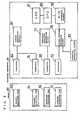
- a sensor 70which was described above, is shown on the left side of FIG. 8 .
- a measuring apparatus 71comprises connectors 72, 74 and 84 which are connected to the leads 12, 14 and 34, respectively.
- the connector 84is connected to the connector 74 via a switch 76, and they are connected to a reference potential generating circuit 77 via a switch 75.
- To the connector 72is connected a potential generating circuit 82 and a current/voltage conversion circuit 78.
- the current/voltage conversion circuit 78converts, into voltage, the current flowing between the working electrode and the counter electrode upon application of a positive potential to the working electrode with respect to the counter electrode connected to the reference potential generating circuit 77 for output.
- the output voltageis converted into pulses by an A/D conversion circuit 79.
- a CPU 80calculates the amount of a substrate contained in a sample based on the pulses output from the A/D conversion circuit 79. The calculated value is displayed on an LCD 81.
- the sensor 70is set to the above-described measuring apparatus 71, and the switch 76 of the measuring apparatus is closed to short-circuit the first counter electrode 13 and the second counter electrode 33 while the switch 75 is closed.
- the samplereadily reaches the reagent layer in the sample supply pathway by capillarity.
- the measuring apparatusstarts operating and a timer starts measuring time.
- glucoseis oxidized by GOD while the electron mediator potassium ferricyanide is reduced to potassium ferrocyanide.
- a voltage of 300 mVis applied to the working electrode 11 with respect to the counter electrode from the potential generating circuit 82, and a current oxidizing the potassium ferrocyanide flows between the working electrode 11 and the counter electrode.
- the glucose concentration based on this current valueis displayed on the LCD 81.
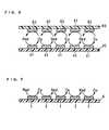
- FIG. 2illustrates the flow of the current oxidizing the electron mediator in the vicinity of the electrode system of the biosensor in this embodiment.
- the working electrode 11 and the first counter electrode 13have a plurality of branches, and these branches are alternately arranged to form the electrode system.
- the second counter electrode 33is disposed so as to oppose this electrode system.
- the concentration of the oxidation/reduction species on the second counter electrode 33is reflected in the sensor response.
- the sensor response of the biosensor of this embodimentincreases in comparison with conventional biosensors.
- the second counter electrodeis disposed only at a position opposite to the working electrode. That is, as illustrated in FIG. 3 , the second counter electrode 33 is trimmed into a comb shape having a plurality of branches 33a.
- the second counter electrodehas a structure in which their branches 33a are opposed to the branches of the working electrode in the sample supply pathway. With this structure, the concentration of the reduced form electron mediator in the vicinity of the second counter electrode is heightened, probably because the current density in the vicinity of the second counter electrode immediately above the working electrode is heightened, or for other reasons. Since the sensor response depends on the concentration of the reduced form electron mediator, highly sensitive quantification of the substrate consequently becomes possible.
- FIG. 4is a decomposed perspective view of a glucose sensor from which the reagent layer and surfactant layer are omitted in this embodiment.
- a first electrode systemwhich is composed of a substantially comb-shaped first working electrode 41 comprising a plurality of branches, a first working electrode lead 42, a substantially comb-shaped first counter electrode 43 comprising a plurality of branches and a first counter electrode lead 44, is formed on a first base plate 40.
- a second electrode systemwhich is composed of a substantially comb-shaped second working electrode 61 comprising a plurality of branches, a second working electrode lead 62, a substantially comb-shaped second counter electrode 63 comprising a plurality of branches and a second counter electrode lead 64.
- the number of the branches of the working electrode and the counter electrodeis not to be limited to the number as illustrated in this figure in the same manner as in Embodiment 1.
- the second base plate 60has an air vent 65.
- the first base plate 40is provided with electrically connecting holes 48 and 49 for bringing terminals of an apparatus in contact with the second counter electrode lead 62 and the second working electrode lead 64.
- the second base plate 60is provided with electrically connecting holes 68 and 69 for bringing terminals of the apparatus in contact with the first working electrode lead 42 and the first counter electrode lead 44.
- a spacer member 50is bonded to the first base plate 40, a reagent layer is formed thereon, and the second base plate 60 is bonded thereto in a positional relation as indicated by the dash-dotted lines of FIG. 4 , to fabricate a glucose sensor.
- the spacer 50has a slit 51 for forming a sample supply pathway. An open end 52 of the slit 51 serves as a sample supply inlet.
- the sample supply pathwayis formed in the slit 51 of the spacer 50 between the first base plate 40 and the second base plate 60.
- the second counter electrode 63is disposed at a position opposite to the first working electrode 41
- the second working electrode 61is disposed at a position opposite to the first counter electrode 43.
- the slit 51 of the spacer 50defines the area of the first working electrode 41, first counter electrode 43, second working electrode 61 and second counter electrode 63 facing the sample supply pathway (electrode area).
- the total electrode area of the first working electrode 41 and the second working electrode 61is made equal to the electrode area of the working electrode 11 of Embodiment 1.
- the electrode system formedis denser in comparison with the sensor of Embodiment 1. Therefore, in comparison with the sensor of Embodiment 1, the size of the slit 51 can be made smaller, resulting in a reduction in the amount of the sample.
- the second counter electrodebe disposed at a position opposite to the first working electrode and that the second working electrode be disposed at a position opposite to the first counter electrode.
- FIG. 5illustrates the arrangement of the electrodes in the sample supply pathway of the biosensor in this embodiment.
- the first working electrode 41 and the first counter electrode 43 disposed on the first base plate 40are alternately arranged, and the second working electrode 61 and the second counter electrode 63 disposed on the second base plate 60 are alternately arranged; the first working electrode 41 and the second counter electrode 63 are opposed to each other, and the first counter electrode 43 and the second working electrode 61 are opposed to each other.
- a denser electrode systemcan be disposed when the total area of the working electrode is the same. Therefore, the volume of the sample supply pathway can be reduced, and hence reduction of the amount of a sample becomes possible.
- FIG. 6is a decomposed perspective view of a glucose sensor from which the reagent layer and surfactant layer are omitted in this embodiment.
- the structureis the same as that of Embodiment 1 except for the formation of a reference electrode 15 and its lead 16 on a first base plate 10 and formation of an electrically connecting hole 38 for bringing a working electrode lead 12 and the lead 16 of the reference electrode 15 in contact with two corresponding terminals of an apparatus on a second base plate 30.
- a sensor 80which was described above, is shown on the left side of FIG. 9 .
- a measuring apparatus 81comprises connectors 72, 96, 74 and 84 which are connected to the leads 12, 16, 14 and 34, respectively.
- the connector 74 and the connector 84are connected to a current generating circuit 97.
- To the connector 72is connected a potential generating circuit 82 and a current/voltage conversion circuit 78.
- the current/voltage conversion circuit 78, an A/D conversion circuit 79 and a CPU 80perform the same functions as those of the measuring apparatus as described in Embodiment 1.
- the measuring apparatusWhen the sensor 80 is set to the above-described measuring apparatus 81 and a sample containing glucose is brought in contact with a sample supply inlet 23 at the end of the sensor, the sample readily reaches the reagent layer in the sample supply pathway by capillarity.
- the measuring apparatusUpon the detection of arrival of the sample at the electrode system, the measuring apparatus starts operating and a timer starts measuring time. After a lapse of an appropriate time from the start of operation of the apparatus, a voltage of 300 mV is applied to a working electrode 11 with respect to the reference electrode 15 from the potential generating circuit 82, and a current oxidizing potassium ferrocyanide flows between the working electrode 11 and the counter electrode. The value of this current is displayed on an LCD 81 as the glucose concentration of the sample by the functions of the current/voltage conversion circuit 78 and other components of the measuring apparatus in the same manner as in Embodiment 1.
- the sensor response value of the biosensor according to this embodimentincreases in comparison with conventional biosensors for the same reasons as those of Embodiment 1. Further, owing to the provision of the reference electrode 15, the potential of the working electrode 11 is stabilized in comparison with the case without the reference electrode. Therefore, measurements with higher accuracy become possible.
- first base plate and the second base plate of the present inventionit is possible to use any electrically insulating material having sufficient rigidity during storage and measurement.
- Such examplesinclude thermoplastic resins, such as polyethylene, polystyrene, poly vinyl chloride, polyamide and saturated polyester resin, or thermosetting resins, such as urea resin, melamine resin, phenol resin, epoxy resin and unsaturated polyester resin.
- thermoplastic resinssuch as polyethylene, polystyrene, poly vinyl chloride, polyamide and saturated polyester resin
- thermosetting resinssuch as urea resin, melamine resin, phenol resin, epoxy resin and unsaturated polyester resin.
- polyethylene terephthalateis preferable in terms of the adhesion to the electrode.
- the spacer membersimilar materials to those of the first and second base plates may be used. Also, the function of the spacer may be performed by the binder for bonding the first base plate and the second base plate together.
- the working electrodeit is possible to use any conductive material which is not subject to oxidation upon oxidation of the electron mediator.
- the counter electrodeit is possible to use any commonly used conductive material, for example, carbon and noble metal such as palladium, gold and platinum. It is preferable that the working electrode and the counter electrode be composed mainly of noble metal among them. This enables the electrodes to be worked more finely and therefore enables higher accuracy and reduction of sample amount.
- an electrodeis produced by sputtering noble metal over a base plate to form a noble metal film and trimming it by a laser.
- the oxidoreductaseone adequate for the substrate, which is a measuring target, contained in the sample may be used.
- Such examplesinclude fructose dehydrogenase, glucose oxidase, glucose dehydrogenase, alcohol oxidase, lactate oxidase, cholesterol oxidase, xanthine oxidase, amino acid oxidase, etc.
- the reagent layermay contain a hydrophilic polymer.
- Various hydrophilic polymersmay be used. Such examples include hydroxyethyl cellulose, hydroxypropyl cellulose, methyl cellulose, ethyl cellulose, ethylhydroxyethyl cellulose, carboxymethyl cellulose, polyvinyl pyrrolidone, polyvinyl alcohol, polyamino acid such as polylysine, polystyrene sulfonate, gelatin and its derivatives, polyacrylic acid and its salts, polymethacrylic acid and its salts, starch and its derivatives, and a polymer of maleic anhydride or its salt. Among them, carboxymethyl cellulose, hydroxyethyl cellulose and hydroxypropyl cellulose are preferred.
- each of the working electrode 11 and the first counter electrode 13was a comb-shaped electrode having 65 branches at intervals of 15 ⁇ m, each branch being 5 ⁇ m in width, and the working electrode branches and the counter electrode branches were arranged alternately at intervals of 5 ⁇ m.
- the reagent layerwas formed by dropping an aqueous solution containing GOD and potassium ferricyanide onto the electrode system of the first base plate 10 and drying it. Further, a surfactant layer containing lecithin as a surfactant was formed on the reagent layer.
- the first counter electrode 13 and the second counter electrode 33were short-circuited to make them function as a counter electrode.
- a samplewas supplied to the sample supply pathway from the sample supply inlet 23. 25 seconds after the supply of the sample, a voltage of 300 mV was applied to the working electrode 11 with respect to the counter electrode. 5 seconds after the voltage application, the value of the current flowing between the working electrode 11 and the counter electrode was measured, and the measured current value was converted into a voltage value by the current/voltage conversion circuit 78. This voltage value serves as an index of the magnitude of the current flowing between the electrodes. As a result, the current response observed was proportional to the glucose concentration of the sample.
- Example 1As a result, for both of the sensors of Example 1 and the comparative example, the current response observed was proportional to the glucose concentration of the sample. However, the biosensor of Example 1 yielded higher response values than the biosensor of the comparative example. This high sensitivity is probably because in Example 1, due to the presence of the second counter electrode, the reduced form electron mediator which has diffused in a direction perpendicular to the working electrode is also oxidized on the second counter electrode, and because due to the suppression of growth of the diffusion layer on the working electrode, the concentration of the oxidation/reduction species on the second counter electrode is reflected in the sensor response, or for other reasons.
- each of the first working electrode 41 and the second counter electrode 63was a comb-shaped electrode having 32 branches at intervals of 15 ⁇ m, each branch being 5 ⁇ m in width
- each of the second working electrode 61 and the first counter electrode 43was a comb-shaped electrode having 33 branches at intervals of 15 ⁇ m, each branch being 5 ⁇ m in width.
- the first working electrode branches and the first counter electrode brancheswere arranged alternately at intervals of 5 ⁇ m
- the second working electrode branches and the second counter electrode brancheswere arranged alternately at intervals of 5 ⁇ m.
- the sensorwas fabricated such that the first working electrode was opposed to the second counter electrode and the second working electrode was opposed to the first counter electrode.
- the reagent layer and the surfactant layerhave the same structure as in Example 1.
- Example 2In the same manner as in Example 1, using solutions containing certain amounts of glucose as samples, glucose concentrations were measured.
- the first counter electrode 43 and the second counter electrode 63were short-circuited to make them function as a counter electrode, and the first working electrode 41 and the second working electrode 61 were short-circuited to make them function as a working electrode.
- a samplewas supplied to the sample supply pathway from the sample supply inlet 52, and 25 seconds later, a voltage of 300 mV was applied to the working electrode with respect to the counter electrode. As a result, the response value obtained was higher in comparison with the sensor of the comparative example used in Example 1.
- a sensor which was the same as that of Example 1 except for the addition of the reference electrode 15 as illustrated in FIG. 6was produced.
- the sensorwas set to a measuring apparatus as illustrated in FIG. 9 , and a sample was supplied to the sample supply pathway from the sample supply inlet 23. 25 seconds after the supply of the sample, a voltage of 300 mV was applied to the working electrode 11 with respect to the reference electrode 15. 5 seconds after the voltage application, the value of the current flowing between the working electrode 11 and the counter electrode was measured, and the measured current value was converted into a voltage value by the current/voltage conversion circuit 78.
- the sensor of Example 3yielded highly sensitive response similarly to the sensor of Example 1. Further, since it had the reference electrode, the potential of the working electrode could be stabilized in comparison with the two-electrode system and the variation in response value was therefore reduced.
- the width of each branch of the working electrode and the counter electrodewas 10 ⁇ m and the distance between the working electrode and the counter electrode on the same base plate was 5 ⁇ m, but there is no limitation thereto.
- the time from the supply of the sample until the voltage applicationwas 25 seconds, but there is no limitation thereto.
- the timemay be any time during which enzyme reactions proceed to such an extent that it becomes possible to obtain current response correlated with the substrate concentration of the sample and may be preferably 180 seconds or less.
- the voltage applied to the electrode systemwas 300 mV, but there is no limitation thereto. It may be any voltage at which the electrode reaction of the electron mediator proceeds on the working electrode.
- the distance between the working electrode and the counter electrodeis preferably in a range of 1 to 50 ⁇ m.
- the distance between the electrode of the first base plate and the electrode of the second base plateis defined by the thickness of the spacer.
- the thickness of the spaceris preferably in a range of 1 to 50 ⁇ m.
- potassium ferricyanidewas used as the electron mediator in the examples, there is no limitation thereto, and p-benzoquinone, phenazine methosulfate, methylene blue, ferrocene derivatives and the like may also be used. Also, when oxygen is used as the electron mediator, current response is obtained. As the electron mediator, two or more of these may be used.
- first counter electrode and the second counter electrodewere short-circuited to serve as the counter electrode in the foregoing examples, there is no limitation thereto, and the first counter electrode and the second counter electrode may be caused to function independently.
- a constant potential capable of reducing the electron mediatormay be applied to the first counter electrode, and only the second counter electrode may be used as the counter electrode.
- aqueous solution of ⁇ -D-glucosewas used as a sample in the foregoing examples, there is no limitation thereto.
- biological samplessuch as whole blood, plasma, serum, interstitial fluid, saliva and urine may be used.
- whole blood sampleinclude capillary blood which is taken by puncturing the skin of a finger or an arm, venous blood and arterial blood.
Landscapes
- Chemical & Material Sciences (AREA)
- Life Sciences & Earth Sciences (AREA)
- Health & Medical Sciences (AREA)
- Organic Chemistry (AREA)
- Zoology (AREA)
- Engineering & Computer Science (AREA)
- Proteomics, Peptides & Aminoacids (AREA)
- Wood Science & Technology (AREA)
- Biochemistry (AREA)
- Biophysics (AREA)
- General Health & Medical Sciences (AREA)
- Immunology (AREA)
- Molecular Biology (AREA)
- Analytical Chemistry (AREA)
- Physics & Mathematics (AREA)
- Microbiology (AREA)
- Bioinformatics & Cheminformatics (AREA)
- General Engineering & Computer Science (AREA)
- Biotechnology (AREA)
- Genetics & Genomics (AREA)
- Emergency Medicine (AREA)
- Hematology (AREA)
- Chemical Kinetics & Catalysis (AREA)
- Electrochemistry (AREA)
- General Physics & Mathematics (AREA)
- Pathology (AREA)
- Apparatus Associated With Microorganisms And Enzymes (AREA)
- Investigating Or Analysing Biological Materials (AREA)
Description
- The present invention relates to a biosensor for rapid and highly accurate quantification of a substrate contained in a sample.
- Methods using polarimetry, colorimetry, reductimetry and a variety of chromatographies have been developed as methods for quantitative analysis of sugars such as sucrose and glucose. These methods, however, are all poorly specific to sugars and hence have poor accuracy. Among these methods, the polarimetry is simple in manipulation, but is largely affected by the temperature during the manipulation. Therefore, the polarimetry is not suitable as a method of simple quantification of sugars at home, etc. for ordinary people.
- Recently, various types of biosensors utilizing the specific catalytic action of enzymes have been under development.
- The following will describe a method of glucose quantification as one example of the method of quantifying a substrate contained in a sample. As an electrochemical method of glucose quantification, a method using glucose oxidase (EC 1.1.3.4: hereinafter abbreviated to GOD) as an enzyme and an oxygen electrode or a hydrogen peroxide electrode is generally well-known (see "Biosensor" ed. by Shuichi Suzuki, Kodansha, for example).
- GOD selectively oxidizes β-D-glucose as a substrate to D-glucono-δ-lactone using oxygen as an electron mediator. In the oxidation reaction process by GOD in the presence of oxygen, oxygen is reduced to hydrogen peroxide. The decreased amount of oxygen is measured by the oxygen electrode, or the increased amount of hydrogen peroxide is measured by the hydrogen peroxide electrode. Since the decreased amount of oxygen and the increased amount of hydrogen peroxide are proportional to the content of glucose in the sample, glucose quantification is possible based on the decreased amount of oxygen or the increased amount of hydrogen peroxide.
- The above method utilizes the specificity of enzyme reactions to enable accurate quantification of glucose in the sample. However, as speculated from the reaction process, it has a drawback in that the measurement is largely affected by the oxygen concentration of the sample, and if the oxygen is absent in the sample, the measurement is infeasible.
- Under such circumstances, glucose sensors of new type have been developed which use as the electron mediator potassium ferricyanide, an organic compound or a metal complex such as a ferrocene derivative and a quinone derivative without using oxygen as the electron mediator. In the sensors of this type, the reduced form of the electron mediator which results from the enzyme reaction is oxidized on a working electrode, and based on the amount of this oxidation current, the concentration of glucose contained in the sample can be determined. Simultaneously, on a counter electrode, a reaction in which the oxidized form of the electron mediator is reduced into the reduced form of the electron mediator proceeds. With the use of such an organic compound or metal complex as the electron mediator in place of oxygen, it is possible to form a reagent layer comprising a known amount of GOD and the electron mediator which are carried in a stable state and a precise manner on the electrodes, so that accurate quantification of glucose is possible without being affected by the oxygen concentration of the sample. In this case, it is also possible to integrate the reagent layer containing the enzyme and electron mediator, in an almost dry state, with an electrode system, and hence disposable glucose sensors based on this technique have recently been receiving a lot of attention. A typical example thereof is a biosensor disclosed in Japanese Patent Publication No.
2517153 - According to the measurement method using the above-described glucose sensor, with the use of a sample whose amount is in the order of several µl, the concentration of a substrate in the sample can be determined readily. However, in recent years, it is anxiously desired in various fields to develop biosensors capable of measuring a sample in an extremely small amount of not more than 1 µl. When a sample in an extremely small amount is measured by a conventional electrochemical glucose sensor, the amount of glucose in the sample is also extremely small, and hence the sensitivity of the measurement may lower in some cases.
- Thus, there has been developed a biosensor which utilizes two substantially comb-shaped electrodes comprising a plurality of branches that are arranged alternately on a base plate.
FIG. 7 is a sectional view of the biosensor in the vicinity of the electrode system. In this type of sensor, the oxidized form of an electron mediator, which results from the oxidation at a first electrode 1 disposed on a base plate 5, can be reduced back to the reduced form at a neighboringsecond electrode 3, and the reduced form can be oxidized again at a neighboring first electrode 1. Accordingly, the value of the current flowing through the first electrode 1 increases apparently, so that more sensitive glucose quantification is possible in comparison with conventional biosensors. - This approach is applicable not only to glucose quantification but also to quantification of other substrates contained in a sample.
- However, since there has been a demand in recent years for further reduction in the amount of a sample necessary for making a measurement, glucose sensors having higher sensitivity are anxiously desired in various fields.
- In view of the above, an object of the present invention is to provide a highly sensitive biosensor capable of giving a good response even when the amount of a sample is extremely small.
EP-A-0,984,069 discloses a biosensor having the features of the precharacterizing portion of claim 1.JP-A-9159644 - According to a first aspect of the present invention, there is provided a biosensor comprising:
- a first insulating base plate which has a working electrode and a first counter electrode;
- a second insulating base plate which has an electrode and which is disposed at a position opposite to the first insulating base plate;
- a reagent system comprising an oxidoreductase; and
- a sample supply pathway formed between the first and second insulating base plates, wherein the reagent system is exposed in said sample supply pathway;
- the working electrode comprises a plurality of branches;
- the first counter electrode comprises a plurality of branches, said branches of the working electrode and the first counter electrode being arranged alternately;
- the electrode of the second insulating base plate is a second counter electrode; and
- said branches of the working electrode and the first counter electrode that are arranged alternately, and the second counter electrode are exposed in said sample supply pathway.
- It is preferred that the second counter electrode be disposed only at positions opposite to the working electrode in the sample supply pathway.
- According to a second aspect of the present invention, there is provided a biosensor comprising:
- a first insulating base plate which has a first working electrode comprising a plurality of branches and a first counter electrode comprising a plurality of branches, the branches of the first working electrode and the first counter electrode being arranged alternately;
- a second insulating base plate which has a second working electrode comprising a plurality of branches and a second counter electrode comprising a plurality of branches, the branches of the second working electrode and the second counter electrode being arranged alternately;
- a reagent system comprising an oxidoreductase; and
- a sample supply pathway formed between the first and second insulating base plates, wherein the branches of the first working electrode and the first counter electrode that are arranged alternately, the branches of the second working electrode and the second counter electrode that are arranged alternately, and the reagent system are exposed in the sample supply pathway.
- It is preferred that the second counter electrode be disposed at a position opposite to the first working electrode and that the second working electrode be disposed at a position opposite to the first counter electrode.
- According to a third aspect of the present invention, there is provided a method for measuring a substrate in a sample, using the biosensor in accordance with the first aspect of the present invention, the method comprising the steps of:
- supplying a sample to said sample supply pathway;
- applying a voltage between the working electrode and the first and second counter electrodes; and
- measuring a current flowing between the working electrode and the first and second counter electrodes.
- Preferably, the reagent system further comprises an electron mediator, and the step of applying the voltage is such that the working electrode oxidizes a reduced form of the electron mediator.
- Preferably, the first and second counter electrodes function to reduce an oxidized form of the electron mediator.
FIG. 1 is an exploded perspective view of a glucose sensor from which the reagent layer is omitted in one embodiment of the present invention.FIG. 2 is a cross sectional view showing the arrangement of electrodes in a sample supply pathway of the same sensor.FIG. 3 is a cross sectional view showing another example of the arrangement of electrodes in a sample supply pathway of a sensor.FIG. 4 is an exploded perspective view of a biosensor from which the reagent layer is omitted in another embodiment of the present invention.FIG. 5 is a cross sectional view showing the arrangement of electrodes in a sample supply pathway of the same sensor.FIG. 6 is an exploded perspective view of a biosensor from which the reagent layer is omitted in still another embodiment of the present invention.FIG. 7 is a cross sectional view showing the arrangement of electrodes of a conventional biosensor.FIG. 8 is a block diagram showing the circuit structure of a measuring apparatus to which a sensor in one embodiment of the present invention is set.FIG. 9 is a block diagram showing the circuit structure of a measuring apparatus to which a sensor in another embodiment of the present invention is set.- In the following, embodiments of the biosensor of the present invention will be described with reference to drawings.
- The shape and structure of for example the first base plate and the second plate and the shape, material and branch number of the electrodes are not to be limited to the embodiments as described below.
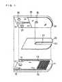
FIG. 1 is a longitudinal cross-sectional view of a glucose sensor from which the reagent layer and surfactant layer are omitted in this embodiment.- 10 represents a first base plate comprising an electrically insulating material. On the
base plate 10, there is formed, by photo lithography, an electrode system which is composed of a substantially comb-shaped workingelectrode 11 comprising a plurality of branches and itslead 12 and a substantially comb-shapedfirst counter electrode 13 comprising a plurality of branches and itslead 14. As a specific method, for example, palladium is sputtered over the base plate, and the palladium film is covered with a resist. Subsequently, the resultant palladium film is provided with masking having the same shape as the electrode system, exposed to light, developed, and etched. Finally, the resist is removed to form an electrode system having a predetermined shape. In this figure, each of the workingelectrode 11 and the first counter electrode is illustrated as having six branches, but there is no limitation thereto. As described in the examples given below, it may be composed of dozens of branches. Over asecond base plate 30 comprising an electrically insulating material, palladium is sputtered, to form asecond counter electrode 33 and itslead 34. Thesecond base plate 30 has anair vent 35. Thefirst base plate 10 is provided with an electrically connectinghole 17 for bringing a terminal of an apparatus in contact with the secondcounter electrode lead 34, and thesecond base plate 30 is provided with electrically connectingholes electrode lead 12 and thelead 14 of thefirst counter electrode 13. - A
spacer member 20 comprising an insulating material has aslit 21 for forming a sample supply pathway that will be described below. After thespacer member 20 is bonded to thefirst base plate 10, a reagent layer is formed by dropping a solution for forming a reagent layer from theslit 21 on the electrode system and drying it. The reagent layer contains GOD, which is an oxidoreductase, and potassium ferricyanide, which is an electron mediator. It is preferable to form a surfactant layer comprising lecithin as a surfactant on the reagent layer. - Next, the
second base plate 30 is bonded to thefirst base plate 10 that is joined with thespacer 20 in a positional relation as indicated by the dash-dotted lines ofFIG. 1 , to fabricate a glucose sensor. Then, between the first base plate and the second base plate in theslit 21 of thespacer 20 is formed a sample supply pathway. Anopen end 23 of theslit 21 serves as a sample supply inlet, and theair vent 35 of thesecond base plate 30 is the end of the sample supply pathway. - In the sample supply pathway, the electrode system and the second counter electrode are disposed so as to face each other. And, the
spacer 20 defines the area of the workingelectrode 11,first counter electrode 13 andsecond counter electrode 33 facing the sample supply pathway - In the following, a measuring apparatus for measuring glucose with the use of this sensor will be described with reference to
FIG. 8 . - A sensor 70, which was described above, is shown on the left side of
FIG. 8 . In this figure, only the workingelectrode lead 12, the firstcounter electrode lead 14 and the secondcounter electrode lead 34 are shown. Meanwhile, a measuring apparatus 71 comprisesconnectors leads connector 84 is connected to theconnector 74 via aswitch 76, and they are connected to a referencepotential generating circuit 77 via aswitch 75. To theconnector 72 is connected apotential generating circuit 82 and a current/voltage conversion circuit 78. The current/voltage conversion circuit 78 converts, into voltage, the current flowing between the working electrode and the counter electrode upon application of a positive potential to the working electrode with respect to the counter electrode connected to the referencepotential generating circuit 77 for output. The output voltage is converted into pulses by an A/D conversion circuit 79. ACPU 80 calculates the amount of a substrate contained in a sample based on the pulses output from the A/D conversion circuit 79. The calculated value is displayed on anLCD 81. - The sensor 70 is set to the above-described measuring apparatus 71, and the
switch 76 of the measuring apparatus is closed to short-circuit thefirst counter electrode 13 and thesecond counter electrode 33 while theswitch 75 is closed. When a sample containing glucose is brought in contact with thesample supply inlet 23 at the end of the sensor, the sample readily reaches the reagent layer in the sample supply pathway by capillarity. Upon the detection of arrival of the sample at the electrode system, the measuring apparatus starts operating and a timer starts measuring time. When the reagent layer is dissolved by the sample, glucose is oxidized by GOD while the electron mediator potassium ferricyanide is reduced to potassium ferrocyanide. After a lapse of an appropriate time from the start of operation of the apparatus, a voltage of 300 mV is applied to the workingelectrode 11 with respect to the counter electrode from thepotential generating circuit 82, and a current oxidizing the potassium ferrocyanide flows between the workingelectrode 11 and the counter electrode. By the functions of the current/voltage conversion circuit 78 and other components of the measuring apparatus, the glucose concentration based on this current value is displayed on theLCD 81. FIG. 2 illustrates the flow of the current oxidizing the electron mediator in the vicinity of the electrode system of the biosensor in this embodiment. In this embodiment, the workingelectrode 11 and thefirst counter electrode 13 have a plurality of branches, and these branches are alternately arranged to form the electrode system. Thesecond counter electrode 33 is disposed so as to oppose this electrode system. With this structure, the oxidized form electron mediator which results from the oxidation at the workingelectrode 11 disposed on thefirst base plate 10 is reduced at the adjoiningfirst counter electrode 13, while the reduced form electron mediator which has diffused in a direction perpendicular to the workingelectrode 11 is also reduced back to the reduced form on thesecond counter electrode 33 disposed on thesecond base plate 30. Further, due to the suppression of the growth of the diffusion layer on the workingelectrode 11, the concentration of the oxidation/reduction species on thesecond counter electrode 33 is reflected in the sensor response. For these reasons, the sensor response of the biosensor of this embodiment increases in comparison with conventional biosensors.- Therein, it is preferred that the second counter electrode is disposed only at a position opposite to the working electrode. That is, as illustrated in
FIG. 3 , thesecond counter electrode 33 is trimmed into a comb shape having a plurality ofbranches 33a. The second counter electrode has a structure in which theirbranches 33a are opposed to the branches of the working electrode in the sample supply pathway. With this structure, the concentration of the reduced form electron mediator in the vicinity of the second counter electrode is heightened, probably because the current density in the vicinity of the second counter electrode immediately above the working electrode is heightened, or for other reasons. Since the sensor response depends on the concentration of the reduced form electron mediator, highly sensitive quantification of the substrate consequently becomes possible. FIG. 4 is a decomposed perspective view of a glucose sensor from which the reagent layer and surfactant layer are omitted in this embodiment.- Following the same procedure as that of Embodiment 1, a first electrode system, which is composed of a substantially comb-shaped first working
electrode 41 comprising a plurality of branches, a first workingelectrode lead 42, a substantially comb-shapedfirst counter electrode 43 comprising a plurality of branches and a firstcounter electrode lead 44, is formed on afirst base plate 40. On asecond base plate 60 is formed a second electrode system, which is composed of a substantially comb-shaped second workingelectrode 61 comprising a plurality of branches, a secondworking electrode lead 62, a substantially comb-shapedsecond counter electrode 63 comprising a plurality of branches and a secondcounter electrode lead 64. The number of the branches of the working electrode and the counter electrode is not to be limited to the number as illustrated in this figure in the same manner as in Embodiment 1. Thesecond base plate 60 has anair vent 65. Thefirst base plate 40 is provided with electrically connectingholes counter electrode lead 62 and the second workingelectrode lead 64. Likewise, thesecond base plate 60 is provided with electrically connectingholes electrode lead 42 and the firstcounter electrode lead 44. - Thereafter, a
spacer member 50 is bonded to thefirst base plate 40, a reagent layer is formed thereon, and thesecond base plate 60 is bonded thereto in a positional relation as indicated by the dash-dotted lines ofFIG. 4 , to fabricate a glucose sensor. Thespacer 50 has a slit 51 for forming a sample supply pathway. Anopen end 52 of the slit 51 serves as a sample supply inlet. - In this way, the sample supply pathway is formed in the slit 51 of the
spacer 50 between thefirst base plate 40 and thesecond base plate 60. In the sample supply pathway, as illustrated inFIG. 4 , thesecond counter electrode 63 is disposed at a position opposite to the first workingelectrode 41, and the second workingelectrode 61 is disposed at a position opposite to thefirst counter electrode 43. The slit 51 of thespacer 50 defines the area of the first workingelectrode 41,first counter electrode 43, second workingelectrode 61 andsecond counter electrode 63 facing the sample supply pathway (electrode area). In the sensor of this embodiment, the total electrode area of the first workingelectrode 41 and the second workingelectrode 61 is made equal to the electrode area of the workingelectrode 11 of Embodiment 1. However, since the second workingelectrode 61 is disposed on thesecond base plate 60, the electrode system formed is denser in comparison with the sensor of Embodiment 1. Therefore, in comparison with the sensor of Embodiment 1, the size of the slit 51 can be made smaller, resulting in a reduction in the amount of the sample. - Therein, it is preferable that the second counter electrode be disposed at a position opposite to the first working electrode and that the second working electrode be disposed at a position opposite to the first counter electrode.
FIG. 5 illustrates the arrangement of the electrodes in the sample supply pathway of the biosensor in this embodiment. The first workingelectrode 41 and thefirst counter electrode 43 disposed on thefirst base plate 40 are alternately arranged, and the second workingelectrode 61 and thesecond counter electrode 63 disposed on thesecond base plate 60 are alternately arranged; the first workingelectrode 41 and thesecond counter electrode 63 are opposed to each other, and thefirst counter electrode 43 and the second workingelectrode 61 are opposed to each other. Accordingly, in comparison with the biosensor as illustrated inFIG. 2 , a denser electrode system can be disposed when the total area of the working electrode is the same. Therefore, the volume of the sample supply pathway can be reduced, and hence reduction of the amount of a sample becomes possible.FIG. 6 is a decomposed perspective view of a glucose sensor from which the reagent layer and surfactant layer are omitted in this embodiment.- The structure is the same as that of Embodiment 1 except for the formation of a
reference electrode 15 and itslead 16 on afirst base plate 10 and formation of an electrically connectinghole 38 for bringing a workingelectrode lead 12 and thelead 16 of thereference electrode 15 in contact with two corresponding terminals of an apparatus on asecond base plate 30. - In the following, a measuring apparatus for measuring glucose with the use of this sensor will be described with reference to
FIG. 9 . - A
sensor 80, which was described above, is shown on the left side ofFIG. 9 . In this figure, only the workingelectrode lead 12, thelead 16 of the first reference electrode, acounter electrode lead 14 and alead 34 of a second counter electrode are shown. Meanwhile, a measuringapparatus 81 comprisesconnectors leads connector 74 and theconnector 84 are connected to acurrent generating circuit 97. To theconnector 72 is connected apotential generating circuit 82 and a current/voltage conversion circuit 78. The current/voltage conversion circuit 78, an A/D conversion circuit 79 and aCPU 80 perform the same functions as those of the measuring apparatus as described in Embodiment 1. - When the
sensor 80 is set to the above-describedmeasuring apparatus 81 and a sample containing glucose is brought in contact with asample supply inlet 23 at the end of the sensor, the sample readily reaches the reagent layer in the sample supply pathway by capillarity. Upon the detection of arrival of the sample at the electrode system, the measuring apparatus starts operating and a timer starts measuring time. After a lapse of an appropriate time from the start of operation of the apparatus, a voltage of 300 mV is applied to a workingelectrode 11 with respect to thereference electrode 15 from thepotential generating circuit 82, and a current oxidizing potassium ferrocyanide flows between the workingelectrode 11 and the counter electrode. The value of this current is displayed on anLCD 81 as the glucose concentration of the sample by the functions of the current/voltage conversion circuit 78 and other components of the measuring apparatus in the same manner as in Embodiment 1. - The sensor response value of the biosensor according to this embodiment increases in comparison with conventional biosensors for the same reasons as those of Embodiment 1. Further, owing to the provision of the
reference electrode 15, the potential of the workingelectrode 11 is stabilized in comparison with the case without the reference electrode. Therefore, measurements with higher accuracy become possible. - As the first base plate and the second base plate of the present invention, it is possible to use any electrically insulating material having sufficient rigidity during storage and measurement. Such examples include thermoplastic resins, such as polyethylene, polystyrene, poly vinyl chloride, polyamide and saturated polyester resin, or thermosetting resins, such as urea resin, melamine resin, phenol resin, epoxy resin and unsaturated polyester resin. Among them, polyethylene terephthalate is preferable in terms of the adhesion to the electrode. As the spacer member, similar materials to those of the first and second base plates may be used. Also, the function of the spacer may be performed by the binder for bonding the first base plate and the second base plate together.
- As the working electrode, it is possible to use any conductive material which is not subject to oxidation upon oxidation of the electron mediator. As the counter electrode, it is possible to use any commonly used conductive material, for example, carbon and noble metal such as palladium, gold and platinum. It is preferable that the working electrode and the counter electrode be composed mainly of noble metal among them. This enables the electrodes to be worked more finely and therefore enables higher accuracy and reduction of sample amount.
- Although this embodiment employed photo lithography as a manufacturing method of the electrode system, there is no limitation thereto. For example, an electrode is produced by sputtering noble metal over a base plate to form a noble metal film and trimming it by a laser.
- As the oxidoreductase, one adequate for the substrate, which is a measuring target, contained in the sample may be used. Such examples include fructose dehydrogenase, glucose oxidase, glucose dehydrogenase, alcohol oxidase, lactate oxidase, cholesterol oxidase, xanthine oxidase, amino acid oxidase, etc.
- The reagent layer may contain a hydrophilic polymer. Various hydrophilic polymers may be used. Such examples include hydroxyethyl cellulose, hydroxypropyl cellulose, methyl cellulose, ethyl cellulose, ethylhydroxyethyl cellulose, carboxymethyl cellulose, polyvinyl pyrrolidone, polyvinyl alcohol, polyamino acid such as polylysine, polystyrene sulfonate, gelatin and its derivatives, polyacrylic acid and its salts, polymethacrylic acid and its salts, starch and its derivatives, and a polymer of maleic anhydride or its salt. Among them, carboxymethyl cellulose, hydroxyethyl cellulose and hydroxypropyl cellulose are preferred.
- In the following, the present invention will be described more specifically with reference to examples.
- A glucose sensor having the structure as illustrated in Embodiment 1 was produced. In this example, each of the working
electrode 11 and thefirst counter electrode 13 was a comb-shaped electrode having 65 branches at intervals of 15 µm, each branch being 5 µm in width, and the working electrode branches and the counter electrode branches were arranged alternately at intervals of 5 µm. - The reagent layer was formed by dropping an aqueous solution containing GOD and potassium ferricyanide onto the electrode system of the
first base plate 10 and drying it. Further, a surfactant layer containing lecithin as a surfactant was formed on the reagent layer. - Thereafter, using solutions containing certain amounts of glucose as samples, glucose concentrations were measured. In this example, the
first counter electrode 13 and thesecond counter electrode 33 were short-circuited to make them function as a counter electrode. A sample was supplied to the sample supply pathway from thesample supply inlet 23. 25 seconds after the supply of the sample, a voltage of 300 mV was applied to the workingelectrode 11 with respect to the counter electrode. 5 seconds after the voltage application, the value of the current flowing between the workingelectrode 11 and the counter electrode was measured, and the measured current value was converted into a voltage value by the current/voltage conversion circuit 78. This voltage value serves as an index of the magnitude of the current flowing between the electrodes. As a result, the current response observed was proportional to the glucose concentration of the sample. - As a comparative example, response measurements were performed similarly on a sensor whose counter electrode was the
first counter electrode 13 only. In this case, theswitch 75 was closed, but theswitch 76 remained open. - As a result, for both of the sensors of Example 1 and the comparative example, the current response observed was proportional to the glucose concentration of the sample. However, the biosensor of Example 1 yielded higher response values than the biosensor of the comparative example. This high sensitivity is probably because in Example 1, due to the presence of the second counter electrode, the reduced form electron mediator which has diffused in a direction perpendicular to the working electrode is also oxidized on the second counter electrode, and because due to the suppression of growth of the diffusion layer on the working electrode, the concentration of the oxidation/reduction species on the second counter electrode is reflected in the sensor response, or for other reasons.
- A glucose sensor having the structure as illustrated in Embodiment 2 was produced. In this example, each of the first working
electrode 41 and thesecond counter electrode 63 was a comb-shaped electrode having 32 branches at intervals of 15 µm, each branch being 5 µm in width, and each of the second workingelectrode 61 and thefirst counter electrode 43 was a comb-shaped electrode having 33 branches at intervals of 15 µm, each branch being 5 µm in width. The first working electrode branches and the first counter electrode branches were arranged alternately at intervals of 5 µm, and the second working electrode branches and the second counter electrode branches were arranged alternately at intervals of 5 µm. Then, the sensor was fabricated such that the first working electrode was opposed to the second counter electrode and the second working electrode was opposed to the first counter electrode. The reagent layer and the surfactant layer have the same structure as in Example 1. - In the same manner as in Example 1, using solutions containing certain amounts of glucose as samples, glucose concentrations were measured. In this example, the
first counter electrode 43 and thesecond counter electrode 63 were short-circuited to make them function as a counter electrode, and the first workingelectrode 41 and the second workingelectrode 61 were short-circuited to make them function as a working electrode. A sample was supplied to the sample supply pathway from thesample supply inlet 52, and 25 seconds later, a voltage of 300 mV was applied to the working electrode with respect to the counter electrode. As a result, the response value obtained was higher in comparison with the sensor of the comparative example used in Example 1. - A sensor which was the same as that of Example 1 except for the addition of the
reference electrode 15 as illustrated inFIG. 6 was produced. The sensor was set to a measuring apparatus as illustrated inFIG. 9 , and a sample was supplied to the sample supply pathway from thesample supply inlet 23. 25 seconds after the supply of the sample, a voltage of 300 mV was applied to the workingelectrode 11 with respect to thereference electrode 15. 5 seconds after the voltage application, the value of the current flowing between the workingelectrode 11 and the counter electrode was measured, and the measured current value was converted into a voltage value by the current/voltage conversion circuit 78. - The sensor of Example 3 yielded highly sensitive response similarly to the sensor of Example 1. Further, since it had the reference electrode, the potential of the working electrode could be stabilized in comparison with the two-electrode system and the variation in response value was therefore reduced.
- In the foregoing examples, the width of each branch of the working electrode and the counter electrode was 10 µm and the distance between the working electrode and the counter electrode on the same base plate was 5 µm, but there is no limitation thereto. Also, the time from the supply of the sample until the voltage application was 25 seconds, but there is no limitation thereto. The time may be any time during which enzyme reactions proceed to such an extent that it becomes possible to obtain current response correlated with the substrate concentration of the sample and may be preferably 180 seconds or less.
- The voltage applied to the electrode system was 300 mV, but there is no limitation thereto. It may be any voltage at which the electrode reaction of the electron mediator proceeds on the working electrode.
- With respect to the distance between the working electrode and the counter electrode, the distance between the working electrode branch and the counter electrode branch formed on the same base plate is preferably in a range of 1 to 50 µm. The distance between the electrode of the first base plate and the electrode of the second base plate is defined by the thickness of the spacer. The thickness of the spacer is preferably in a range of 1 to 50 µm.
- Although potassium ferricyanide was used as the electron mediator in the examples, there is no limitation thereto, and p-benzoquinone, phenazine methosulfate, methylene blue, ferrocene derivatives and the like may also be used. Also, when oxygen is used as the electron mediator, current response is obtained. As the electron mediator, two or more of these may be used.
- Although the first counter electrode and the second counter electrode were short-circuited to serve as the counter electrode in the foregoing examples, there is no limitation thereto, and the first counter electrode and the second counter electrode may be caused to function independently. For example, a constant potential capable of reducing the electron mediator may be applied to the first counter electrode, and only the second counter electrode may be used as the counter electrode.
- Although the aqueous solution of β-D-glucose was used as a sample in the foregoing examples, there is no limitation thereto. For example, biological samples such as whole blood, plasma, serum, interstitial fluid, saliva and urine may be used. Examples of the whole blood sample include capillary blood which is taken by puncturing the skin of a finger or an arm, venous blood and arterial blood.
- As described above, according to the present invention, it is possible to obtain a highly sensitive biosensor capable of yielding good response even when the amount of a sample is extremely small.
Claims (7)
- A biosensor comprising:a first insulating base plate (10) which has a working electrode (11) and a first counter electrode (13);a second insulating base plate (30) which has an electrode (33) and which is disposed at a position opposite to the first insulating base plate (10);a reagent system comprising an oxidoreductase; anda sample supply pathway (21) formed between the first and second insulating base plates (10,30), wherein the reagent system is exposed in said sample supply pathway;characterized in that:the working electrode (11) comprises a plurality of branches;the first counter electrode (13) comprises a plurality of branches, said branches of the working electrode and the first counter electrode being arranged alternately;the electrode (33) of the second insulating base plate (30) is a second counter electrode; andsaid branches of the working electrode (11) and the first counter electrode (13) that are arranged alternately, and the second counter electrode (33) are exposed in said sample supply pathway.
- The biosensor in accordance with claim 1, wherein the second counter electrode (33a) is disposed only at positions opposite to the working electrode (11) in said sample supply pathway (21).
- A biosensor comprising:a first insulating base plate (40) which has a first working electrode (41) comprising a plurality of branches and a first counter electrode (43) comprising a plurality of branches, said branches of the first working electrode and the first counter electrode being arranged alternately;a second insulating base plate (60) which has a second working electrode (61) comprising a plurality of branches and a second counter electrode (63) comprising a plurality of branches, said branches of the second working electrode and the second counter electrode being arranged alternately;a reagent system comprising an oxidoreductase; anda sample supply pathway (51) formed between the first and second insulating base plates (40,60), wherein said branches of the first working electrode (41) and the first counter electrode (43) that are arranged alternately, said branches of the second working electrode (61) and the second counter electrode (63) that are arranged alternately, and the reagent system are exposed in said sample supply pathway (51).
- The biosensor in accordance with claim 3, wherein the second counter electrode (63) is disposed at a position opposite to the first working electrode (41), and the second working electrode (61) is disposed at a position opposite to the first counter electrode (43).
- A method for measuring a substrate in a sample, using the biosensor in accordance with claim 1 or 2, said method comprising the steps of:supplying a sample to said sample supply pathway (21);applying a voltage between the working electrode (11) and the first and second counter electrodes (13,33); andmeasuring a current flowing between the working electrode (11) and the first and second counter electrodes (13,33).
- The method for measuring a substrate in a sample in accordance with claim 5, wherein the reagent system further comprises an electron mediator, and the step of applying the voltage is such that the working electrode (11) oxidizes a reduced form of the electron mediator.
- The method for measuring a substrate in a sample in accordance with claim 6, wherein the first and second counter electrodes (13,33) function to reduce an oxidized form of the electron mediator.
Applications Claiming Priority (3)
| Application Number | Priority Date | Filing Date | Title |
|---|---|---|---|
| JP2001161244 | 2001-05-29 | ||
| JP2001161244 | 2001-05-29 | ||
| PCT/JP2002/005129WO2002097418A1 (en) | 2001-05-29 | 2002-05-27 | Biosensor |
Publications (3)
| Publication Number | Publication Date |
|---|---|
| EP1288654A1 EP1288654A1 (en) | 2003-03-05 |
| EP1288654A4 EP1288654A4 (en) | 2003-07-02 |
| EP1288654B1true EP1288654B1 (en) | 2008-10-22 |
Family
ID=19004550
Family Applications (1)
| Application Number | Title | Priority Date | Filing Date |
|---|---|---|---|
| EP02774074AExpired - LifetimeEP1288654B1 (en) | 2001-05-29 | 2002-05-27 | Biosensor |
Country Status (7)
| Country | Link |
|---|---|
| US (1) | US7022218B2 (en) |
| EP (1) | EP1288654B1 (en) |
| JP (1) | JP3690683B2 (en) |
| CN (1) | CN1205474C (en) |
| DE (1) | DE60229476D1 (en) |
| ES (1) | ES2315407T3 (en) |
| WO (1) | WO2002097418A1 (en) |
Families Citing this family (117)
| Publication number | Priority date | Publication date | Assignee | Title |
|---|---|---|---|---|
| US6036924A (en) | 1997-12-04 | 2000-03-14 | Hewlett-Packard Company | Cassette of lancet cartridges for sampling blood |
| US7407811B2 (en)* | 1997-12-22 | 2008-08-05 | Roche Diagnostics Operations, Inc. | System and method for analyte measurement using AC excitation |
| US7390667B2 (en)* | 1997-12-22 | 2008-06-24 | Roche Diagnostics Operations, Inc. | System and method for analyte measurement using AC phase angle measurements |
| US8071384B2 (en) | 1997-12-22 | 2011-12-06 | Roche Diagnostics Operations, Inc. | Control and calibration solutions and methods for their use |
| US6391005B1 (en) | 1998-03-30 | 2002-05-21 | Agilent Technologies, Inc. | Apparatus and method for penetration with shaft having a sensor for sensing penetration depth |
| US6645359B1 (en) | 2000-10-06 | 2003-11-11 | Roche Diagnostics Corporation | Biosensor |
| US20050103624A1 (en) | 1999-10-04 | 2005-05-19 | Bhullar Raghbir S. | Biosensor and method of making |
| US7073246B2 (en) | 1999-10-04 | 2006-07-11 | Roche Diagnostics Operations, Inc. | Method of making a biosensor |
| US6540890B1 (en) | 2000-11-01 | 2003-04-01 | Roche Diagnostics Corporation | Biosensor |
| DE10057832C1 (en) | 2000-11-21 | 2002-02-21 | Hartmann Paul Ag | Blood analysis device has syringe mounted in casing, annular mounting carrying needles mounted behind test strip and being swiveled so that needle can be pushed through strip and aperture in casing to take blood sample |
| US8641644B2 (en) | 2000-11-21 | 2014-02-04 | Sanofi-Aventis Deutschland Gmbh | Blood testing apparatus having a rotatable cartridge with multiple lancing elements and testing means |
| DE10058397A1 (en)* | 2000-11-24 | 2002-06-06 | Siemens Ag | Arrangement for an electrochemical analysis method and its use |
| US7041068B2 (en) | 2001-06-12 | 2006-05-09 | Pelikan Technologies, Inc. | Sampling module device and method |
| US7981056B2 (en) | 2002-04-19 | 2011-07-19 | Pelikan Technologies, Inc. | Methods and apparatus for lancet actuation |
| US9795747B2 (en) | 2010-06-02 | 2017-10-24 | Sanofi-Aventis Deutschland Gmbh | Methods and apparatus for lancet actuation |
| WO2002101359A2 (en) | 2001-06-12 | 2002-12-19 | Pelikan Technologies, Inc. | Integrated blood sampling analysis system with multi-use sampling module |
| US9427532B2 (en) | 2001-06-12 | 2016-08-30 | Sanofi-Aventis Deutschland Gmbh | Tissue penetration device |
| EP1395185B1 (en) | 2001-06-12 | 2010-10-27 | Pelikan Technologies Inc. | Electric lancet actuator |
| JP4209767B2 (en) | 2001-06-12 | 2009-01-14 | ペリカン テクノロジーズ インコーポレイテッド | Self-optimized cutting instrument with adaptive means for temporary changes in skin properties |
| AU2002344825A1 (en) | 2001-06-12 | 2002-12-23 | Pelikan Technologies, Inc. | Method and apparatus for improving success rate of blood yield from a fingerstick |
| JP4272051B2 (en) | 2001-06-12 | 2009-06-03 | ペリカン テクノロジーズ インコーポレイテッド | Blood sampling apparatus and method |
| US8337419B2 (en) | 2002-04-19 | 2012-12-25 | Sanofi-Aventis Deutschland Gmbh | Tissue penetration device |
| US7344507B2 (en) | 2002-04-19 | 2008-03-18 | Pelikan Technologies, Inc. | Method and apparatus for lancet actuation |
| US9226699B2 (en) | 2002-04-19 | 2016-01-05 | Sanofi-Aventis Deutschland Gmbh | Body fluid sampling module with a continuous compression tissue interface surface |
| US7749174B2 (en) | 2001-06-12 | 2010-07-06 | Pelikan Technologies, Inc. | Method and apparatus for lancet launching device intergrated onto a blood-sampling cartridge |
| US6814844B2 (en) | 2001-08-29 | 2004-11-09 | Roche Diagnostics Corporation | Biosensor with code pattern |
| US7344894B2 (en) | 2001-10-16 | 2008-03-18 | Agilent Technologies, Inc. | Thermal regulation of fluidic samples within a diagnostic cartridge |
| ATE479089T1 (en)* | 2001-11-16 | 2010-09-15 | Stefan Ufer | FLEXIBLE SENSOR AND MANUFACTURING METHOD |
| US8221334B2 (en) | 2002-04-19 | 2012-07-17 | Sanofi-Aventis Deutschland Gmbh | Method and apparatus for penetrating tissue |
| US7291117B2 (en) | 2002-04-19 | 2007-11-06 | Pelikan Technologies, Inc. | Method and apparatus for penetrating tissue |
| US9248267B2 (en) | 2002-04-19 | 2016-02-02 | Sanofi-Aventis Deustchland Gmbh | Tissue penetration device |
| US7524293B2 (en) | 2002-04-19 | 2009-04-28 | Pelikan Technologies, Inc. | Method and apparatus for penetrating tissue |
| US7563232B2 (en) | 2002-04-19 | 2009-07-21 | Pelikan Technologies, Inc. | Method and apparatus for penetrating tissue |
| US7582099B2 (en) | 2002-04-19 | 2009-09-01 | Pelikan Technologies, Inc | Method and apparatus for penetrating tissue |
| US7674232B2 (en) | 2002-04-19 | 2010-03-09 | Pelikan Technologies, Inc. | Method and apparatus for penetrating tissue |
| US8579831B2 (en) | 2002-04-19 | 2013-11-12 | Sanofi-Aventis Deutschland Gmbh | Method and apparatus for penetrating tissue |
| US8267870B2 (en) | 2002-04-19 | 2012-09-18 | Sanofi-Aventis Deutschland Gmbh | Method and apparatus for body fluid sampling with hybrid actuation |
| US9314194B2 (en) | 2002-04-19 | 2016-04-19 | Sanofi-Aventis Deutschland Gmbh | Tissue penetration device |
| US8784335B2 (en) | 2002-04-19 | 2014-07-22 | Sanofi-Aventis Deutschland Gmbh | Body fluid sampling device with a capacitive sensor |
| US7717863B2 (en) | 2002-04-19 | 2010-05-18 | Pelikan Technologies, Inc. | Method and apparatus for penetrating tissue |
| US7491178B2 (en) | 2002-04-19 | 2009-02-17 | Pelikan Technologies, Inc. | Method and apparatus for penetrating tissue |
| US9795334B2 (en) | 2002-04-19 | 2017-10-24 | Sanofi-Aventis Deutschland Gmbh | Method and apparatus for penetrating tissue |
| US7648468B2 (en) | 2002-04-19 | 2010-01-19 | Pelikon Technologies, Inc. | Method and apparatus for penetrating tissue |
| US7481776B2 (en) | 2002-04-19 | 2009-01-27 | Pelikan Technologies, Inc. | Method and apparatus for penetrating tissue |
| US7410468B2 (en) | 2002-04-19 | 2008-08-12 | Pelikan Technologies, Inc. | Method and apparatus for penetrating tissue |
| US7331931B2 (en) | 2002-04-19 | 2008-02-19 | Pelikan Technologies, Inc. | Method and apparatus for penetrating tissue |
| US7141058B2 (en) | 2002-04-19 | 2006-11-28 | Pelikan Technologies, Inc. | Method and apparatus for a body fluid sampling device using illumination |
| US7976476B2 (en) | 2002-04-19 | 2011-07-12 | Pelikan Technologies, Inc. | Device and method for variable speed lancet |
| US7297122B2 (en) | 2002-04-19 | 2007-11-20 | Pelikan Technologies, Inc. | Method and apparatus for penetrating tissue |
| US7708701B2 (en) | 2002-04-19 | 2010-05-04 | Pelikan Technologies, Inc. | Method and apparatus for a multi-use body fluid sampling device |
| US7892183B2 (en) | 2002-04-19 | 2011-02-22 | Pelikan Technologies, Inc. | Method and apparatus for body fluid sampling and analyte sensing |
| US7909778B2 (en) | 2002-04-19 | 2011-03-22 | Pelikan Technologies, Inc. | Method and apparatus for penetrating tissue |
| US8702624B2 (en) | 2006-09-29 | 2014-04-22 | Sanofi-Aventis Deutschland Gmbh | Analyte measurement device with a single shot actuator |
| US7371247B2 (en) | 2002-04-19 | 2008-05-13 | Pelikan Technologies, Inc | Method and apparatus for penetrating tissue |
| US7547287B2 (en) | 2002-04-19 | 2009-06-16 | Pelikan Technologies, Inc. | Method and apparatus for penetrating tissue |
| US7374544B2 (en) | 2002-04-19 | 2008-05-20 | Pelikan Technologies, Inc. | Method and apparatus for penetrating tissue |
| US7232451B2 (en) | 2002-04-19 | 2007-06-19 | Pelikan Technologies, Inc. | Method and apparatus for penetrating tissue |
| US7901362B2 (en) | 2002-04-19 | 2011-03-08 | Pelikan Technologies, Inc. | Method and apparatus for penetrating tissue |
| US7229458B2 (en) | 2002-04-19 | 2007-06-12 | Pelikan Technologies, Inc. | Method and apparatus for penetrating tissue |
| AT411627B (en)* | 2002-08-23 | 2004-03-25 | Hoffmann La Roche | DEVICE FOR CHECKING THE POSITIONING AND BUBBLE CLEARANCE OF A MEDICAL MICRO SAMPLE IN A FLOW MEASURING CELL |
| CA2511389C (en)* | 2002-12-26 | 2016-10-18 | Meso Scale Technologies, Llc. | Assay cartridges and methods of using the same |
| US8574895B2 (en) | 2002-12-30 | 2013-11-05 | Sanofi-Aventis Deutschland Gmbh | Method and apparatus using optical techniques to measure analyte levels |
| CA2519267A1 (en)* | 2003-03-20 | 2004-09-30 | Asahi Kasei Life & Living Corporation | Oxygen indicator and package |
| US7850621B2 (en) | 2003-06-06 | 2010-12-14 | Pelikan Technologies, Inc. | Method and apparatus for body fluid sampling and analyte sensing |
| WO2006001797A1 (en) | 2004-06-14 | 2006-01-05 | Pelikan Technologies, Inc. | Low pain penetrating |
| EP1635700B1 (en) | 2003-06-13 | 2016-03-09 | Sanofi-Aventis Deutschland GmbH | Apparatus for a point of care device |
| US7452457B2 (en)* | 2003-06-20 | 2008-11-18 | Roche Diagnostics Operations, Inc. | System and method for analyte measurement using dose sufficiency electrodes |
| US7645421B2 (en) | 2003-06-20 | 2010-01-12 | Roche Diagnostics Operations, Inc. | System and method for coding information on a biosensor test strip |
| US7867369B2 (en)* | 2003-06-20 | 2011-01-11 | Roche Diagnostics Operations, Inc. | Biosensor with multiple electrical functionalities |
| US7645373B2 (en)* | 2003-06-20 | 2010-01-12 | Roche Diagnostic Operations, Inc. | System and method for coding information on a biosensor test strip |
| US8206565B2 (en) | 2003-06-20 | 2012-06-26 | Roche Diagnostics Operation, Inc. | System and method for coding information on a biosensor test strip |
| US8058077B2 (en)* | 2003-06-20 | 2011-11-15 | Roche Diagnostics Operations, Inc. | Method for coding information on a biosensor test strip |
| US8148164B2 (en) | 2003-06-20 | 2012-04-03 | Roche Diagnostics Operations, Inc. | System and method for determining the concentration of an analyte in a sample fluid |
| US8071030B2 (en) | 2003-06-20 | 2011-12-06 | Roche Diagnostics Operations, Inc. | Test strip with flared sample receiving chamber |
| US7604721B2 (en) | 2003-06-20 | 2009-10-20 | Roche Diagnostics Operations, Inc. | System and method for coding information on a biosensor test strip |
| US8679853B2 (en) | 2003-06-20 | 2014-03-25 | Roche Diagnostics Operations, Inc. | Biosensor with laser-sealed capillary space and method of making |
| JP4447009B2 (en)* | 2003-06-20 | 2010-04-07 | エフ ホフマン−ラ ロッシュ アクチェン ゲゼルシャフト | Test strip with slot vent opening |
| US7718439B2 (en) | 2003-06-20 | 2010-05-18 | Roche Diagnostics Operations, Inc. | System and method for coding information on a biosensor test strip |
| US7597793B2 (en) | 2003-06-20 | 2009-10-06 | Roche Operations Ltd. | System and method for analyte measurement employing maximum dosing time delay |
| US8282576B2 (en) | 2003-09-29 | 2012-10-09 | Sanofi-Aventis Deutschland Gmbh | Method and apparatus for an improved sample capture device |
| EP1680014A4 (en) | 2003-10-14 | 2009-01-21 | Pelikan Technologies Inc | METHOD AND DEVICE FOR A VARIABLE USER INTERFACE |
| EP1707953B1 (en)* | 2003-12-04 | 2015-07-01 | Panasonic Healthcare Holdings Co., Ltd. | Method of measuring hematocrit (Hct) |
| CN100472210C (en) | 2003-12-04 | 2009-03-25 | 松下电器产业株式会社 | Method for measuring blood components and sensor and measuring device used in the method |
| US7822454B1 (en) | 2005-01-03 | 2010-10-26 | Pelikan Technologies, Inc. | Fluid sampling device with improved analyte detecting member configuration |
| US8668656B2 (en) | 2003-12-31 | 2014-03-11 | Sanofi-Aventis Deutschland Gmbh | Method and apparatus for improving fluidic flow and sample capture |
| EP3115777B1 (en)* | 2004-04-19 | 2020-01-08 | PHC Holdings Corporation | Method for measuring blood components |
| WO2006011062A2 (en) | 2004-05-20 | 2006-02-02 | Albatros Technologies Gmbh & Co. Kg | Printable hydrogel for biosensors |
| WO2005120365A1 (en) | 2004-06-03 | 2005-12-22 | Pelikan Technologies, Inc. | Method and apparatus for a fluid sampling device |
| US7569126B2 (en) | 2004-06-18 | 2009-08-04 | Roche Diagnostics Operations, Inc. | System and method for quality assurance of a biosensor test strip |
| US7556723B2 (en)* | 2004-06-18 | 2009-07-07 | Roche Diagnostics Operations, Inc. | Electrode design for biosensor |
| GB0428130D0 (en)* | 2004-12-22 | 2005-01-26 | Oxford Biosensors Ltd | Selective HDL cholesterol assay |
| US8652831B2 (en) | 2004-12-30 | 2014-02-18 | Sanofi-Aventis Deutschland Gmbh | Method and apparatus for analyte measurement test time |
| US8057404B2 (en)* | 2005-10-12 | 2011-11-15 | Panasonic Corporation | Blood sensor, blood testing apparatus, and method for controlling blood testing apparatus |
| JP2008096235A (en)* | 2006-10-11 | 2008-04-24 | Sharp Corp | Electrochemical measurement microchip |
| KR100812691B1 (en)* | 2007-03-19 | 2008-03-13 | 영동제약 주식회사 | Biosensor for Disease Diagnosis Using Electrode |
| CN101303347B (en)* | 2007-04-20 | 2013-07-31 | 天津亿朋医疗器械有限公司 | Biological sensor |
| AU2013204842B2 (en)* | 2007-07-23 | 2016-01-28 | Agamatrix, Inc. | Electrochemical test strip |
| AU2016200514B2 (en)* | 2007-07-23 | 2017-03-30 | Agamatrix, Inc. | Electrochemical test strip |
| EP2179027A4 (en)* | 2007-07-23 | 2013-12-04 | Agamatrix Inc | Electrochemical test strip |
| TWI435076B (en)* | 2007-10-31 | 2014-04-21 | Arkray Inc | Biosensor |
| KR100958307B1 (en)* | 2008-01-30 | 2010-05-19 | 한국과학기술연구원 | Biosensor comprising 3D metal nanowire gap electrode with integrated nanochannel, manufacturing method thereof and bio disc system including the biosensor |
| EP2265324B1 (en) | 2008-04-11 | 2015-01-28 | Sanofi-Aventis Deutschland GmbH | Integrated analyte measurement system |
| KR101003077B1 (en)* | 2008-10-16 | 2010-12-21 | 세종공업 주식회사 | Structure of Electrochemical Biosensor and Measurement Method Using Biosensor |
| JP5172606B2 (en)* | 2008-10-30 | 2013-03-27 | シスメックス株式会社 | Method and apparatus for specific detection of test substance, and test chip |
| US9375169B2 (en) | 2009-01-30 | 2016-06-28 | Sanofi-Aventis Deutschland Gmbh | Cam drive for managing disposable penetrating member actions with a single motor and motor and control system |
| US20110079522A1 (en)* | 2009-10-02 | 2011-04-07 | Lifescan Scotland Limited | Multi-analyte test strip with inline working electrodes and shared opposing counter/reference electrode |
| US8965476B2 (en) | 2010-04-16 | 2015-02-24 | Sanofi-Aventis Deutschland Gmbh | Tissue penetration device |
| US20120048746A1 (en)* | 2010-08-30 | 2012-03-01 | Cilag Gmbh International | Analyte test strip with electrically distinguishable divided electrode |
| WO2013171815A1 (en)* | 2012-05-17 | 2013-11-21 | パナソニック株式会社 | Electrochemical detector and method for producing same |
| KR101563486B1 (en)* | 2012-06-28 | 2015-10-27 | 지멘스 헬쓰케어 다이아그노스틱스 인크. | Reader device and method of signal amplification |
| WO2014112569A1 (en)* | 2013-01-17 | 2014-07-24 | 田中貴金属工業株式会社 | Biosensor and process for producing same |
| MX381317B (en)* | 2014-07-17 | 2025-03-12 | Siemens Healthcare Diagnostics Inc | SENSOR SET. |
| DE102015005781A1 (en)* | 2015-05-08 | 2016-11-10 | Forschungszentrum Jülich GmbH | Method for producing a device for the electrochemical detection of molecules by means of redox cycling, and device for this and their use |
| WO2017120464A1 (en)* | 2016-01-08 | 2017-07-13 | Siemens Healthcare Diagnostics Inc. | Heating element for sensor array |
| JP2017138164A (en)* | 2016-02-02 | 2017-08-10 | 大日本印刷株式会社 | Electrode structure manufacturing method, sensor electrode manufacturing method, electrode structure, and sensor electrode |
| JP7104997B2 (en)* | 2018-07-09 | 2022-07-22 | 国立研究開発法人物質・材料研究機構 | Diagnostic device, analysis method, and program |
| TWI768560B (en)* | 2020-11-25 | 2022-06-21 | 五鼎生物技術股份有限公司 | Biochemical test chip |
Family Cites Families (13)
| Publication number | Priority date | Publication date | Assignee | Title |
|---|---|---|---|---|
| US5001048A (en)* | 1987-06-05 | 1991-03-19 | Aurthur D. Little, Inc. | Electrical biosensor containing a biological receptor immobilized and stabilized in a protein film |
| JP2590002B2 (en) | 1988-04-25 | 1997-03-12 | 日本電信電話株式会社 | Microelectrode cell for electrochemical measurement and method for producing the same |
| JP2517153B2 (en) | 1989-09-21 | 1996-07-24 | 松下電器産業株式会社 | Biosensor and manufacturing method thereof |
| GB9218376D0 (en) | 1992-08-28 | 1992-10-14 | Cranfield Inst Of Tech | Media for biocatalytic electrochemical reactions in the gaseous phase |
| DE4318519C2 (en) | 1993-06-03 | 1996-11-28 | Fraunhofer Ges Forschung | Electrochemical sensor |
| JPH09159644A (en) | 1995-12-11 | 1997-06-20 | Dainippon Printing Co Ltd | Biosensor and manufacturing method thereof |
| JPH09243590A (en) | 1996-03-08 | 1997-09-19 | Tdk Corp | Micro comb-shaped electrode and its manufacture and electrode unit for electrochemical measurement of solution system |
| JPH1164271A (en)* | 1997-08-18 | 1999-03-05 | Nagoyashi | Current amplification type oxyzen sensor |
| JP2000065777A (en) | 1998-08-21 | 2000-03-03 | Nok Corp | Biosensor |
| JP3267936B2 (en)* | 1998-08-26 | 2002-03-25 | 松下電器産業株式会社 | Biosensor |
| US6338790B1 (en) | 1998-10-08 | 2002-01-15 | Therasense, Inc. | Small volume in vitro analyte sensor with diffusible or non-leachable redox mediator |
| JP2000121593A (en) | 1998-10-13 | 2000-04-28 | Omron Corp | Enzyme electrode |
| DE19916921A1 (en) | 1999-04-14 | 2000-10-19 | Fraunhofer Ges Forschung | Electrical sensor array |
- 2002
- 2002-05-27EPEP02774074Apatent/EP1288654B1/ennot_activeExpired - Lifetime
- 2002-05-27ESES02774074Tpatent/ES2315407T3/ennot_activeExpired - Lifetime
- 2002-05-27USUS10/333,232patent/US7022218B2/ennot_activeExpired - Lifetime
- 2002-05-27WOPCT/JP2002/005129patent/WO2002097418A1/ennot_activeCeased
- 2002-05-27DEDE60229476Tpatent/DE60229476D1/ennot_activeExpired - Lifetime
- 2002-05-27JPJP2003500548Apatent/JP3690683B2/ennot_activeExpired - Lifetime
- 2002-05-27CNCNB028018796Apatent/CN1205474C/ennot_activeExpired - Lifetime
Also Published As
| Publication number | Publication date |
|---|---|
| EP1288654A4 (en) | 2003-07-02 |
| JPWO2002097418A1 (en) | 2004-09-16 |
| DE60229476D1 (en) | 2008-12-04 |
| JP3690683B2 (en) | 2005-08-31 |
| WO2002097418A1 (en) | 2002-12-05 |
| US7022218B2 (en) | 2006-04-04 |
| EP1288654A1 (en) | 2003-03-05 |
| ES2315407T3 (en) | 2009-04-01 |
| US20040005721A1 (en) | 2004-01-08 |
| CN1463361A (en) | 2003-12-24 |
| CN1205474C (en) | 2005-06-08 |
Similar Documents
| Publication | Publication Date | Title |
|---|---|---|
| EP1288654B1 (en) | Biosensor | |
| JP4177662B2 (en) | Biosensor | |
| US6416641B1 (en) | Biosensor | |
| JP3267936B2 (en) | Biosensor | |
| US6340428B1 (en) | Device and method for determining the concentration of a substrate | |
| JP3389106B2 (en) | Electrochemical analysis element | |
| EP2071331B1 (en) | Biosensors with porous chromatographic membranes | |
| EP1482056A2 (en) | Biosensor | |
| JP2001183330A (en) | Biosensor | |
| JP2001330581A (en) | Substrate concentration determination method | |
| JP3267933B2 (en) | Substrate quantification method | |
| US20040020771A1 (en) | Biosensor, adapter used therefor, and measuring device | |
| JP3437016B2 (en) | Biosensor and method of quantifying substrate using the same | |
| JP2004226358A (en) | Biosensor | |
| JP2004004057A (en) | Biosensor, adapter used therefor, and measuring device | |
| JPH08338824A (en) | Biosensor, method for manufacturing biosensor, and method for quantifying specific compound | |
| JP2004156989A (en) | Biosensor |
Legal Events
| Date | Code | Title | Description |
|---|---|---|---|
| PUAI | Public reference made under article 153(3) epc to a published international application that has entered the european phase | Free format text:ORIGINAL CODE: 0009012 | |
| 17P | Request for examination filed | Effective date:20021224 | |
| AK | Designated contracting states | Kind code of ref document:A1 Designated state(s):AT BE CH CY DE DK ES FI FR GB GR IE IT LI LU MC NL PT SE TR Designated state(s):AT BE CH CY DE DK ES FI FR GB GR IE IT LI LU MC NL PT SE TR | |
| A4 | Supplementary search report drawn up and despatched | Effective date:20030516 | |
| GRAP | Despatch of communication of intention to grant a patent | Free format text:ORIGINAL CODE: EPIDOSNIGR1 | |
| RBV | Designated contracting states (corrected) | Designated state(s):DE ES FR GB IT | |
| GRAS | Grant fee paid | Free format text:ORIGINAL CODE: EPIDOSNIGR3 | |
| GRAA | (expected) grant | Free format text:ORIGINAL CODE: 0009210 | |
| AK | Designated contracting states | Kind code of ref document:B1 Designated state(s):DE ES FR GB IT | |
| REG | Reference to a national code | Ref country code:GB Ref legal event code:FG4D | |
| RAP2 | Party data changed (patent owner data changed or rights of a patent transferred) | Owner name:PANASONIC CORPORATION | |
| REF | Corresponds to: | Ref document number:60229476 Country of ref document:DE Date of ref document:20081204 Kind code of ref document:P | |
| REG | Reference to a national code | Ref country code:ES Ref legal event code:FG2A Ref document number:2315407 Country of ref document:ES Kind code of ref document:T3 | |
| PLBE | No opposition filed within time limit | Free format text:ORIGINAL CODE: 0009261 | |
| STAA | Information on the status of an ep patent application or granted ep patent | Free format text:STATUS: NO OPPOSITION FILED WITHIN TIME LIMIT | |
| 26N | No opposition filed | Effective date:20090723 | |
| REG | Reference to a national code | Ref country code:ES Ref legal event code:GC2A Effective date:20120618 | |
| REG | Reference to a national code | Ref country code:DE Ref legal event code:R082 Ref document number:60229476 Country of ref document:DE Representative=s name:TBK, DE | |
| REG | Reference to a national code | Ref country code:GB Ref legal event code:732E Free format text:REGISTERED BETWEEN 20140313 AND 20140319 | |
| REG | Reference to a national code | Ref country code:DE Ref legal event code:R082 Ref document number:60229476 Country of ref document:DE Representative=s name:TBK, DE Effective date:20140324 Ref country code:DE Ref legal event code:R081 Ref document number:60229476 Country of ref document:DE Owner name:PANASONIC CORPORATION, JP Free format text:FORMER OWNER: PANASONIC CORPORATION, KADOMA-SHI, JP Effective date:20140324 Ref country code:DE Ref legal event code:R082 Ref document number:60229476 Country of ref document:DE Representative=s name:TBK, DE Effective date:20140404 Ref country code:DE Ref legal event code:R081 Ref document number:60229476 Country of ref document:DE Owner name:PANASONIC CORPORATION, JP Free format text:FORMER OWNER: PANASONIC HEALTHCARE CO., LTD., TOON-SHI, JP Effective date:20140404 Ref country code:DE Ref legal event code:R081 Ref document number:60229476 Country of ref document:DE Owner name:PANASONIC HEALTHCARE HOLDINGS CO., LTD., JP Free format text:FORMER OWNER: PANASONIC CORPORATION, KADOMA-SHI, OSAKA, JP Effective date:20140324 Ref country code:DE Ref legal event code:R081 Ref document number:60229476 Country of ref document:DE Owner name:PANASONIC HEALTHCARE HOLDINGS CO., LTD., JP Free format text:FORMER OWNER: PANASONIC HEALTHCARE CO., LTD., TOON-SHI, EHIME, JP Effective date:20140404 | |
| REG | Reference to a national code | Ref country code:ES Ref legal event code:PC2A Owner name:PANASONIC HEALTH CO., LTD. Effective date:20140609 | |
| REG | Reference to a national code | Ref country code:ES Ref legal event code:PC2A Owner name:PANASONIC CORPORATION Effective date:20140714 | |
| REG | Reference to a national code | Ref country code:GB Ref legal event code:732E Free format text:REGISTERED BETWEEN 20140814 AND 20140820 | |
| REG | Reference to a national code | Ref country code:DE Ref legal event code:R082 Ref document number:60229476 Country of ref document:DE Representative=s name:TBK, DE | |
| REG | Reference to a national code | Ref country code:FR Ref legal event code:CA Effective date:20140827 Ref country code:FR Ref legal event code:TP Owner name:PANASONIC HEALTHCARE HOLDINGS CO., LTD., JP Effective date:20140827 | |
| REG | Reference to a national code | Ref country code:GB Ref legal event code:732E Free format text:REGISTERED BETWEEN 20141002 AND 20141008 | |
| REG | Reference to a national code | Ref country code:DE Ref legal event code:R082 Ref document number:60229476 Country of ref document:DE Representative=s name:TBK, DE Effective date:20140925 Ref country code:DE Ref legal event code:R081 Ref document number:60229476 Country of ref document:DE Owner name:PANASONIC HEALTHCARE HOLDINGS CO., LTD., JP Free format text:FORMER OWNER: PANASONIC CORPORATION, KADOMA-SHI, OSAKA, JP Effective date:20140925 | |
| REG | Reference to a national code | Ref country code:FR Ref legal event code:TP Owner name:PANASONIC HEALTHCARE HOLDINGS CO., LTD., JP Effective date:20141008 Ref country code:FR Ref legal event code:CD Owner name:PANASONIC HEALTHCARE HOLDINGS CO., LTD., JP Effective date:20141008 | |
| REG | Reference to a national code | Ref country code:ES Ref legal event code:PC2A Owner name:PHC HOLDINGS CO., LTD. Effective date:20141104 | |
| REG | Reference to a national code | Ref country code:ES Ref legal event code:PC2A Owner name:PANASONIC HEALTHCARE HOLDINGS CO., LTD. Effective date:20141219 | |
| REG | Reference to a national code | Ref country code:FR Ref legal event code:TP Owner name:PANASONIC HEALTHCARE HOLDINGS CO., LTD., JP Effective date:20141218 Ref country code:FR Ref legal event code:CA Effective date:20141218 Ref country code:FR Ref legal event code:CD Owner name:PANASONIC HEALTHCARE HOLDINGS CO., LTD., JP Effective date:20141218 | |
| REG | Reference to a national code | Ref country code:FR Ref legal event code:PLFP Year of fee payment:15 | |
| REG | Reference to a national code | Ref country code:FR Ref legal event code:PLFP Year of fee payment:16 | |
| REG | Reference to a national code | Ref country code:FR Ref legal event code:PLFP Year of fee payment:17 | |
| REG | Reference to a national code | Ref country code:ES Ref legal event code:PC2A Owner name:PHC HOLDINGS CORPORATION Effective date:20190123 | |
| REG | Reference to a national code | Ref country code:DE Ref legal event code:R082 Ref document number:60229476 Country of ref document:DE Representative=s name:TBK, DE Ref country code:DE Ref legal event code:R081 Ref document number:60229476 Country of ref document:DE Owner name:PHC HOLDINGS CORP., JP Free format text:FORMER OWNER: PANASONIC HEALTHCARE HOLDINGS CO., LTD., TOKIO, JP | |
| PGFP | Annual fee paid to national office [announced via postgrant information from national office to epo] | Ref country code:ES Payment date:20190604 Year of fee payment:18 | |
| PGFP | Annual fee paid to national office [announced via postgrant information from national office to epo] | Ref country code:FR Payment date:20190410 Year of fee payment:18 | |
| PGFP | Annual fee paid to national office [announced via postgrant information from national office to epo] | Ref country code:GB Payment date:20190522 Year of fee payment:18 | |
| GBPC | Gb: european patent ceased through non-payment of renewal fee | Effective date:20200527 | |
| PG25 | Lapsed in a contracting state [announced via postgrant information from national office to epo] | Ref country code:GB Free format text:LAPSE BECAUSE OF NON-PAYMENT OF DUE FEES Effective date:20200527 Ref country code:FR Free format text:LAPSE BECAUSE OF NON-PAYMENT OF DUE FEES Effective date:20200531 | |
| PGFP | Annual fee paid to national office [announced via postgrant information from national office to epo] | Ref country code:DE Payment date:20210427 Year of fee payment:20 | |
| REG | Reference to a national code | Ref country code:ES Ref legal event code:FD2A Effective date:20211004 | |
| PG25 | Lapsed in a contracting state [announced via postgrant information from national office to epo] | Ref country code:IT Free format text:LAPSE BECAUSE OF NON-PAYMENT OF DUE FEES Effective date:20200527 | |
| PG25 | Lapsed in a contracting state [announced via postgrant information from national office to epo] | Ref country code:ES Free format text:LAPSE BECAUSE OF NON-PAYMENT OF DUE FEES Effective date:20200528 | |
| REG | Reference to a national code | Ref country code:DE Ref legal event code:R071 Ref document number:60229476 Country of ref document:DE |