EP1287804B1 - Device for bringing components together in sterile conditions - Google Patents
Device for bringing components together in sterile conditionsDownload PDFInfo
- Publication number
- EP1287804B1 EP1287804B1EP20020017985EP02017985AEP1287804B1EP 1287804 B1EP1287804 B1EP 1287804B1EP 20020017985EP20020017985EP 20020017985EP 02017985 AEP02017985 AEP 02017985AEP 1287804 B1EP1287804 B1EP 1287804B1
- Authority
- EP
- European Patent Office
- Prior art keywords
- hollow body
- container
- cannula
- cannula holder
- closure
- Prior art date
- Legal status (The legal status is an assumption and is not a legal conclusion. Google has not performed a legal analysis and makes no representation as to the accuracy of the status listed.)
- Expired - Lifetime
Links
- 239000007788liquidSubstances0.000claimsabstractdescription19
- 239000007787solidSubstances0.000claimsabstractdescription8
- 230000000295complement effectEffects0.000claimsdescription5
- 238000004806packaging method and processMethods0.000claimsdescription5
- 238000007689inspectionMethods0.000claims1
- 239000000969carrierSubstances0.000abstract1
- 239000011521glassSubstances0.000description11
- 239000011324beadSubstances0.000description6
- 230000004913activationEffects0.000description4
- 238000006073displacement reactionMethods0.000description4
- 239000002904solventSubstances0.000description4
- 238000000034methodMethods0.000description3
- 239000011888foilSubstances0.000description2
- 239000002184metalSubstances0.000description2
- 238000007789sealingMethods0.000description2
- 241001631457CannulaSpecies0.000description1
- 235000010678Paulownia tomentosaNutrition0.000description1
- 240000002834Paulownia tomentosaSpecies0.000description1
- 208000027418Wounds and injuryDiseases0.000description1
- 230000006378damageEffects0.000description1
- 208000014674injuryDiseases0.000description1
- 238000003780insertionMethods0.000description1
- 230000037431insertionEffects0.000description1
- 238000011169microbiological contaminationMethods0.000description1
- 230000035515penetrationEffects0.000description1
- 239000000825pharmaceutical preparationSubstances0.000description1
- 229940127557pharmaceutical productDrugs0.000description1
- 238000002360preparation methodMethods0.000description1
- 230000000717retained effectEffects0.000description1
- 239000003206sterilizing agentSubstances0.000description1
- 230000000007visual effectEffects0.000description1
Images


Classifications
- A—HUMAN NECESSITIES
- A61—MEDICAL OR VETERINARY SCIENCE; HYGIENE
- A61J—CONTAINERS SPECIALLY ADAPTED FOR MEDICAL OR PHARMACEUTICAL PURPOSES; DEVICES OR METHODS SPECIALLY ADAPTED FOR BRINGING PHARMACEUTICAL PRODUCTS INTO PARTICULAR PHYSICAL OR ADMINISTERING FORMS; DEVICES FOR ADMINISTERING FOOD OR MEDICINES ORALLY; BABY COMFORTERS; DEVICES FOR RECEIVING SPITTLE
- A61J1/00—Containers specially adapted for medical or pharmaceutical purposes
- A61J1/14—Details; Accessories therefor
- A61J1/20—Arrangements for transferring or mixing fluids, e.g. from vial to syringe
- A61J1/2089—Containers or vials which are to be joined to each other in order to mix their contents
- A—HUMAN NECESSITIES
- A61—MEDICAL OR VETERINARY SCIENCE; HYGIENE
- A61J—CONTAINERS SPECIALLY ADAPTED FOR MEDICAL OR PHARMACEUTICAL PURPOSES; DEVICES OR METHODS SPECIALLY ADAPTED FOR BRINGING PHARMACEUTICAL PRODUCTS INTO PARTICULAR PHYSICAL OR ADMINISTERING FORMS; DEVICES FOR ADMINISTERING FOOD OR MEDICINES ORALLY; BABY COMFORTERS; DEVICES FOR RECEIVING SPITTLE
- A61J1/00—Containers specially adapted for medical or pharmaceutical purposes
- A61J1/14—Details; Accessories therefor
- A61J1/20—Arrangements for transferring or mixing fluids, e.g. from vial to syringe
- A61J1/2003—Accessories used in combination with means for transfer or mixing of fluids, e.g. for activating fluid flow, separating fluids, filtering fluid or venting
- A61J1/2006—Piercing means
- A61J1/201—Piercing means having one piercing end
- A—HUMAN NECESSITIES
- A61—MEDICAL OR VETERINARY SCIENCE; HYGIENE
- A61J—CONTAINERS SPECIALLY ADAPTED FOR MEDICAL OR PHARMACEUTICAL PURPOSES; DEVICES OR METHODS SPECIALLY ADAPTED FOR BRINGING PHARMACEUTICAL PRODUCTS INTO PARTICULAR PHYSICAL OR ADMINISTERING FORMS; DEVICES FOR ADMINISTERING FOOD OR MEDICINES ORALLY; BABY COMFORTERS; DEVICES FOR RECEIVING SPITTLE
- A61J1/00—Containers specially adapted for medical or pharmaceutical purposes
- A61J1/14—Details; Accessories therefor
- A61J1/20—Arrangements for transferring or mixing fluids, e.g. from vial to syringe
- A61J1/2003—Accessories used in combination with means for transfer or mixing of fluids, e.g. for activating fluid flow, separating fluids, filtering fluid or venting
- A61J1/2006—Piercing means
- A61J1/2013—Piercing means having two piercing ends
- A—HUMAN NECESSITIES
- A61—MEDICAL OR VETERINARY SCIENCE; HYGIENE
- A61J—CONTAINERS SPECIALLY ADAPTED FOR MEDICAL OR PHARMACEUTICAL PURPOSES; DEVICES OR METHODS SPECIALLY ADAPTED FOR BRINGING PHARMACEUTICAL PRODUCTS INTO PARTICULAR PHYSICAL OR ADMINISTERING FORMS; DEVICES FOR ADMINISTERING FOOD OR MEDICINES ORALLY; BABY COMFORTERS; DEVICES FOR RECEIVING SPITTLE
- A61J1/00—Containers specially adapted for medical or pharmaceutical purposes
- A61J1/14—Details; Accessories therefor
- A61J1/20—Arrangements for transferring or mixing fluids, e.g. from vial to syringe
- A61J1/2003—Accessories used in combination with means for transfer or mixing of fluids, e.g. for activating fluid flow, separating fluids, filtering fluid or venting
- A61J1/2048—Connecting means
- A61J1/2055—Connecting means having gripping means
Definitions
- the inventionrelates to a device for combining a liquid component accommodated in a first container and a solid or liquid component received in a second container under sterile conditions.
- Such a preassemblable deviceis known from the prior art. It is a device for passing a solvent from a bottle into a second bottle containing a pharmaceutical product to dissolve the product.
- a transfer systemis classified as a disposable medical device.
- the two glass bottlesare preassembled in the transfer device. Sterile packaging ensures that storage of the reconstituted product can take up to 36 hours.
- a device of the type mentionedis in the EP 0 737 467 A1 described.
- a secured, directed transferis achieved by first piercing the closure of the first container containing the liquid component by means of a cannula and then displacing a cannula carrier receiving the cannula by means of this container in the direction of the second container receiving the solid or liquid component so that its closure is pierced by means of the cannula.
- the cannula carriertakes a single cannula, which is sufficient for the merging of the components, as prevails before the piercing of the second container in this vacuum.
- the cannula carrieris formed as a plate-shaped, perpendicular to the longitudinal direction of the two containers receiving hollow body oriented body which is connected via retaining webs with the inner wall of the hollow body, wherein the holding webs are rupturable by applying a manual force that is greater than the penetration force of the cannula Piercing the sealing plug of the initially opened container.
- a disadvantage of this deviceis that the cannula carrier initially firmly connected to the hollow body is not defined separated from the hollow body.
- the type of force introductionpossibly an asymmetrical introduction of force, first rupture holding webs in an area of the cannula carrier, which involves the risk that the cannula carrier and thus the cannula in a tilted with respect to the longitudinal direction of the two containers position.
- the resultis that in particular the closure of the second container is not exactly pierced and problems arise when passing the liquid, in particular under the aspect of the applied vacuum.
- the inventionproposes according to the claims 1 and 4, two basic designs of the device.
- a first cylindrical hollow bodyfor receiving the first container in the region of the closure in a receiving opening of this hollow body and a second cylindrical hollow body for receiving the second container in the region of the closure in provided a diametrically arranged receiving opening.
- the first hollow body and the cannula carrierare thus not separable, they represent a permanent assembly.
- the cup-shaped design of the assemblyensures that the assembly, especially in the region of the first hollow body, is precisely guided in the second hollow body.
- the cannula carrierforms the bottom of the pot and the first hollow body, the pot wall, whereby the first hollow body is not extended beyond the cannula carrier out.
- the pot wallshould have at least one guide section which cooperates with at least one guide section of the second hollow body. Due to the precise guidance of the assembly due to its cup-shaped design in the second hollow body ensures that the assembly and thus the cannula support does not tilt.
- the cannulaIn a displacement movement of the cannula carrier, the cannula is defined in the longitudinal direction of the two hollow body moves by moving the first container in the direction of the second container and pierces the shutter.
- the cannula holdertakes the cannula firmly, so that it is not displaceable in the longitudinal direction.
- only one cannulais received by the cannula carrier, wherein there is a vacuum in the second container.
- the liquid component located in the first containerpasses into the second container due to the vacuum mixes with the solid or liquid component located there under sterile conditions.
- the terms "cannula carrier” and “cannula”are to be understood comprehensively.
- the cannula carrier and the cannulacan form two separate components, wherein the cannula carrier is made in particular of plastic and the cannula in particular of metal. But it is quite conceivable to make the cannula carrier and the cannula in one piece, wherein the cannula is designed in the manner of a mandrel or spikes. Preferably, this assembly is made of plastic.
- the spike / spikehas one or two passages according to the circumstances. If there is vacuum in the second bottle, one passage is sufficient.
- the two hollow bodiesare inserted into each other and form the first hollow body and a cup-shaped cannula carrier with at least one of this cannula received separate components, wherein the first hollow body and the cannula carrier inserted into each other and in Guided longitudinal direction of the two hollow bodies are displaceable relative to each other.
- the first hollow body and the cannula carrierdo not form a structural unit. Instead, the cannula carrier, in order to ensure the precise guidance during its displacement, cup-shaped.
- the first hollow bodyserves to receive the first container, while the cannula carrier serves to mount the cannula and its precise guidance in the longitudinal direction of the two hollow bodies.
- the function of the storage of the first hollow body and the storage of the cannulais thus shifted in this design to two basic components, in contrast to the first solution.
- the cannula carriermay well accommodate more than one cannula, depending on the application.
- the pot wallshould have at least one guide section which cooperates with at least one guide section of the first hollow body.
- the first hollow bodyis mounted immovably in inserted in this first container in the second hollow body. If the first container is inserted into the first hollow body, only the advancement of the cup-shaped cannula carrier takes place when advancing the first container.
- the first hollow body or the cup-shaped cannula carrier forming a structural unit with the cannula carrierhas latching means for locking in different positions of the cannula carrier in complementary latching means of the second hollow body. These locking means ensure a defined displacement of the cannula holder and thus the cannula safely. If the closure of the first container is to be pierced before the cannula carrier is advanced and before it comes into contact with the closure of the second container, the detent of the cannula holder in this position must be dimensioned so that it is in contact of the closure of the first container the cannula does not move.
- the puncture resistance of the closure of the second containeris greater than that of the closure of the first container, so that the closure of the second container brings about the resistance with respect to the cannula which, when the first container is advanced, causes the latter Lock is punctured. In this case, the aforementioned detent would not be required.
- the second detentserves to fix the cannula carrier or a component connected thereto in the maximally advanced position. It ensures that when removing the second container from the second hollow body of the cannula carrier is not tightened and therefore the cannula is pulled out of the closure of the second container.
- Essential aspects of the device according to the inventionare thus in handling safety and robustness in the application by a new design of the cannula holder, which is no longer firmly connected to a cylindrical hollow body and is no longer designed as a disc.
- the design as a "pot”allows a much stronger guided movement when activated according to the principle "piston in the cylinder".
- the activation of the devicetakes place in a vertically oriented position by pressure on the first container located above.
- the first and / or second hollow bodyis formed segment-shaped in the region of its container-side end.
- the segmentsform in particular spreading tabs, which can embrace a crimp cap of the respective container.
- the deviceis used in particular in connection with containers which are designed as vials. It is preferably glass vials with a filling volume of 1 to 10 ml.
- the devicehas a visual endpoint display, in which by viewing window reaching the end position of the cannula holder and thus the puncturing of the closure of the second container can be traced by means of the cannula.
- the second hollow bodyis provided for this purpose laterally with the or the viewing windows.
- the deviceFor immediate use, the device, that is, with the two pre-assembled in the hollow containers in a package, especially a soft plastic packaging, sealed. It thus exists during the reconstitution procedure There is no risk of microbiological contamination since the transfer process can take place within the sterile outer packaging and also allows storage of the reconstituted product under sterile conditions.
- the device according to the inventionalso prevents the handling of cannulas with freely accessible needle tips. There is no risk of injury during removal of the product bottle after reconstitution because the cannula carrier is retained in the device.
- the deviceis immediately available because of the pre-assembly of the relevant components. Within a short time, the liquid can be transferred from the first to the second container. This requires a considerable time savings during the preparation process.
- the reconstitutioncan either be prepared beforehand by a single person or take place directly in the sterile area of an operating room.
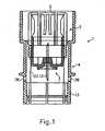
- FIGS. 1 and 2illustrate the device according to the invention, also referred to as the transfer system 1, in a three-part embodiment.
- a first hollow body 2serves for the displaceable reception of a cup-shaped cannula carrier 3 and can be inserted into the second hollow body 4.
- the hollow body 2serves as a holder for a solvent bottle and is provided for this purpose with various parallel to the longitudinal axis of the cylindrical hollow body 2 arranged flexible segments 5. These carry inwardly directed beads 6.
- the opening 7 of the hollow body 2, which is the top of the transfer system when using the transfer,serves to accommodate the solvent bottle.
- In the region of the lower opening 8 of the hollow body 2is provided with an inner guide portion 9 for the cannula carrier 3 received by this, which has an outer complementary guide surface 10, so that the cannula carrier 3 is guided in the hollow body 2 with little play.
- the cup-shaped cannula support 3receives in the region of its bottom portion 11 fixed to a central, axially directed transfer cannula 12, which is provided with pointed ends.
- the length of the transfer cannula 12is dimensioned so that their respective projections, with respect to the bottom portion 1 of the cannula support 3, sufficient to pierce the closures of the containers cooperating with the device.
- the second hollow body 4serves to receive the first hollow body 2 and the cannula carrier 3 in its advanced position.
- the relative to the position of use of the device lower end of the hollow body 4is provided according to the design of the hollow body 2 with flexible segments 13, which in turn have inwardly directed beads 14.
- the second containerwhich receives the solid or liquid component, inserted into the hollow body 4.
- the hollow body 4is widened so that, when the hollow body 2 is inserted in it, its flexible segments have sufficient space to be spread outwards.
- the hollow body 2is held in the hollow body 4 in the region of its lower, outer guide section 17, which is provided with a circumferential one Locking groove 18 is provided, in which in the region of the complementary inner guide portion 19 a local circumferential locking projection 20 engages. In the inserted position of the hollow body 2, this is thus fixed relative to the hollow body 4.
- the cannula support 3has in the region of its outer guide portion 10 has a circumferential latching projection 21, which cooperates in the largely remote from the bottom opening 11 position with an extension 22 in the hollow body 4. If the cannula carrier 3 is acted upon by applying a force directed in the direction of the opening 15, the cannula carrier 3 is advanced until the latching projection 21 rests with a latching groove 23 of the hollow body 4 located further in the front in the hollow body 4. In this position, the cannula carrier 3 rests with its bottom portion 11 against a circumferential annular projection 24 of the hollow body 4.
- FIG. 1illustrates the mounting state of the transfer system 1 when inserted into the hollow body 4 hollow body 2, before advancing the cannula holder 3 in the direction of the opening 15 in the hollow body 4th
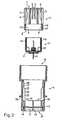
- FIG. 3shows the different steps in the assembly and in the activation of the transfer system 1.
- step ais the Einzelteilildwolf according to FIG. 2 illustrates, further provided for insertion into the hollow body 2 glass bottle 25 which receives the solvent.
- the bottle 25is provided with an elastic, pierceable closure 26 and has a crimp cap 27 in the region of the closure.
- the other, the fixed or designed liquid component receiving glass bottle 28which can be inserted from below into the hollow body 4.
- orientation shown - glass bottle top 25 and glass bottle bottom 28 -is, starting from the mounting state of the transfer system 1 according to FIG. 1 or mounting condition b. in FIG. 3 , the glass bottle 25 inserted into the hollow body 2 and the glass bottle 28 in the hollow body 4.
- FIG. 3illustrates the beads 6 of the segments 5 and the beads 14 of the segments 13, the bottles 25 and 28, wherein the bottle 28 abuts the annular projection 24 of the hollow body 4. If the two bottles 25 and 28 are now pressed towards one another or the glass bottle 25 is pressed further into the hollow body 2, the cannula 12 of the cannula holder 3 remaining in its position pierces the closure 26 of the bottle 25, the bottle having a greater diameter during advancement of the bottle Bottle body, the segments 5 of the hollow body 1 are spread outwards. This condition is too d. in FIG. 3 illustrated.
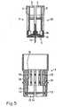
- FIGS. 4 and 5is different from the one after the FIGS. 1 and 2 in that instead of the two components - hollow body 2 and cannula carrier 3 - a component 29 is provided, which unites the function of these two components in itself.
- Matching componentsare in the FIGS. 4 and 5 as well as the functional representation after FIG. 6 for the sake of simplicity designated by the same reference numerals.
- the assembly 29is pot-shaped and is formed by the cylindrical hollow body 2 and the cannula carrier 3.
- the assembly 29is provided with an outer circumferential locking projection 30, whose function is that of the locking projection 21 on the cannula carrier 3 in the embodiment according to the FIGS. 1 and 2 equivalent.
- the outer guide portion 31 of the assembly 29cooperates with the inner guide portion 32 of the hollow body 4, which is provided in the two functional positions of the cannula holder 3 of the assembly 29 with inner locking grooves 33 and 34, in their function of the extension 22 and the locking groove 23 correspond to the hollow body 2 in the embodiment described above.
- the bottles 25 and 28inserted into this, wherein the upper bottle 25 engages with its crimp cap 27 in a circumferential recess 35 of the flexible segments 5 of the assembly 29.
- the segments 5are spread over the bottle body to the outside and the crimp cap 27 of the bottle 25 against the cannula support 3, in particular in the region of the projection 36 which carries the cannula 12 moves.
- the assembly 29is moved out with its locking projection 30 from the locking groove 33 of the hollow body 4.
- the lower end position of the cannula holder 3is to e. in FIG.
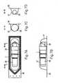
- FIGS. 7A to 7Dillustrate a sealed in a blister foil transfer system 1 with the bottles inserted therein 25 and 28, in a state as in the Figures 3 and 6 to the stage c. is illustrated.
- the Blister sheet 37is welded to a sealing paper 38, which is preferably continuous for a sterilizing agent.
- FIG. 7Ashows the arrangement in a plan view
- FIG. 7Bthis in a side view
- the Figures 7C and 7Dmake cuts according to the lines AA and BB in FIG. 7A represents.
Landscapes
- Health & Medical Sciences (AREA)
- Pharmacology & Pharmacy (AREA)
- Life Sciences & Earth Sciences (AREA)
- Animal Behavior & Ethology (AREA)
- General Health & Medical Sciences (AREA)
- Public Health (AREA)
- Veterinary Medicine (AREA)
- Medical Preparation Storing Or Oral Administration Devices (AREA)
- External Artificial Organs (AREA)
- Sampling And Sample Adjustment (AREA)
Abstract
Description
Translated fromGermanDie Erfindung betrifft eine Vorrichtung zum Zusammenführen einer in einem ersten Behältnis aufgenommenen flüssigen Komponente und einer in einem zweiten Behältnis aufgenommenen festen oder flüssigen Komponente unter sterilen Bedingungen.The invention relates to a device for combining a liquid component accommodated in a first container and a solid or liquid component received in a second container under sterile conditions.
Eine derartige, vormontierbare Vorrichtung ist aus dem Stand der Technik bekannt. Es handelt sich um ein Gerät zum Überleiten eines Lösungsmittels von einer Flasche in eine zweite, ein pharmazeutisches Produkt enthaltende Flasche, um das Produkt zu lösen. Ein solches Überleit-System wird als medizinischer Einmalartikel eingestuft. Um die Handhabung des Rekonstitutionsprozesses zu vereinfachen, werden die beiden Glasflaschen in das Überleitgerät vormontiert. Eine sterile Verpackung gewährleistet, dass die Lagerung des rekonstituierten Produktes bis zu 36 Stunden erfolgen kann.Such a preassemblable device is known from the prior art. It is a device for passing a solvent from a bottle into a second bottle containing a pharmaceutical product to dissolve the product. Such a transfer system is classified as a disposable medical device. In order to simplify the handling of the reconstitution process, the two glass bottles are preassembled in the transfer device. Sterile packaging ensures that storage of the reconstituted product can take up to 36 hours.
Eine Vorrichtung der eingangs genannten Art ist in der
Nachteilig ist bei dieser Vorrichtung, dass der zunächst fest mit dem Hohlkörper verbundene Kanülenträger nicht definiert vom Hohlkörper getrennt wird. Je nach der Art der Krafteinleitung, gegebenenfalls einer unsymmetrischen Krafteinleitung, reißen zunächst Haltestege in einem Bereich des Kanülenträgers, womit die Gefahr besteht, dass der Kanülenträger und damit die Kanüle in eine bezüglich der Längsrichtung der beiden Behältnisse gekippte Position schwenken. Die Folge ist, dass insbesondere der Verschluss des zweiten Behältnisses nicht exakt durchstochen wird und sich Probleme beim Überleiten der Flüssigkeit, insbesondere unter dem Aspekt des anliegenden Vakuums ergeben.A disadvantage of this device is that the cannula carrier initially firmly connected to the hollow body is not defined separated from the hollow body. Depending on the type of force introduction, possibly an asymmetrical introduction of force, first rupture holding webs in an area of the cannula carrier, which involves the risk that the cannula carrier and thus the cannula in a tilted with respect to the longitudinal direction of the two containers position. The result is that in particular the closure of the second container is not exactly pierced and problems arise when passing the liquid, in particular under the aspect of the applied vacuum.
Auch Dokumente
Es ist Aufgabe der vorliegenden Erfindung, eine Vorrichtung der eingangs genannten Art so weiter zu bilden, dass ein exaktes Überleiten der im ersten Behältnis befindlichen Komponente in das zweite Behältnis gewährleistet ist.It is an object of the present invention to provide a device of the type mentioned so on, that an exact passing of the component located in the first container is ensured in the second container.
Die Erfindung schlägt gemäß der Patentansprüche 1 und 4 zwei grundsätzliche Gestaltungen der Vorrichtung vor. Bei beiden Vorrichtungen, die die Merkmale der Vorrichtung gemäß der eingangs genannten Art aufweisen, ist ein erster zylindrischer Hohlkörper zur Aufnahme des ersten Behältnisses im Bereich dessen Verschlusses in einer Aufnahmeöffnung dieses Hohlkörpers und ein zweiter zylindrischer Hohlkörper zur Aufnahme des zweiten Behältnisses im Bereich dessen Verschlusses in einer diametral angeordneten Aufnahmeöffnung vorgesehen.The invention proposes according to the claims 1 and 4, two basic designs of the device. In both devices having the features of the device according to the aforementioned type, a first cylindrical hollow body for receiving the first container in the region of the closure in a receiving opening of this hollow body and a second cylindrical hollow body for receiving the second container in the region of the closure in provided a diametrically arranged receiving opening.
Allerdings sind bei der Vorrichtung gemäß der ersten Gestaltung die beiden Hohlkörper ineinander gesteckt und in deren Längsrichtung geführt relativ zueinander verschiebbar, ferner ist ein eine topfförmige Baueinheit mit dem ersten Hohlkörper bildender Kanülenträger mit mindestens einer von diesem aufgenommenen Kanüle versehen. Der erste Hohlkörper und der Kanülenträger sind somit nicht trennbar, sie stellen eine dauerhafte Baueinheit dar. Die topfförmige Gestaltung der Baueinheit stellt sicher, dass die Baueinheit, insbesondere in deren Bereich des ersten Hohlkörpers, präzise im zweiten Hohlkörper geführt ist. Vorzugsweise bildet der Kanülenträger den Boden des Topfes und der erste Hohlkörper die Topfwandung, womit der erste Hohlkörper nicht über den Kanülenträger hinaus verlängert ist. Um eine sehr genaue Führung zu gewährleisten, sollte die Topfwandung mindestens einen Führungsabschnitt aufweisen, der mit mindestens einem Führungsabschnitt des zweiten Hohlkörpers zusammenwirkt. Durch die präzise Führung der Baueinheit aufgrund deren topfförmiger Gestaltung im zweiten Hohlkörper ist sichergestellt, dass die Baueinheit und damit der Kanülenträger nicht kippt. Bei einer Verschiebebewegung des Kanülenträgers wird die Kanüle definiert in Längsrichtung der beiden Hohlkörper durch das Verschieben mittels des ersten Behältnisses in Richtung des zweiten Behältnisses bewegt und durchsticht dessen Verschluss.However, in the device according to the first embodiment, the two hollow bodies inserted into each other and guided in the longitudinal direction relative to each other displaceable, also a cup-shaped unit with the first hollow body forming cannula carrier is provided with at least one of this recorded cannula. The first hollow body and the cannula carrier are thus not separable, they represent a permanent assembly. The cup-shaped design of the assembly ensures that the assembly, especially in the region of the first hollow body, is precisely guided in the second hollow body. Preferably, the cannula carrier forms the bottom of the pot and the first hollow body, the pot wall, whereby the first hollow body is not extended beyond the cannula carrier out. In order to ensure a very accurate guidance, the pot wall should have at least one guide section which cooperates with at least one guide section of the second hollow body. Due to the precise guidance of the assembly due to its cup-shaped design in the second hollow body ensures that the assembly and thus the cannula support does not tilt. In a displacement movement of the cannula carrier, the cannula is defined in the longitudinal direction of the two hollow body moves by moving the first container in the direction of the second container and pierces the shutter.
In aller Regel nimmt der Kanülenträger die Kanüle fest auf, so dass sie nicht in deren Längsrichtung verschiebbar ist. Vorzugsweise wird von dem Kanülenträger auch nur eine Kanüle aufgenommen, wobei im zweiten Behältnis Vakuum herrscht. Nach dem Bewegen des ersten Behältnisses in Richtung des zweiten Behältnisses und dem Durchstechen des Verschlusses des ersten Behältnisses mittels der Kanüle sowie dem weiteren Vorschieben des ersten Behältnisses und Durchstechen des Verschlusses gelangt die in dem ersten Behältnis befindliche flüssige Komponente aufgrund des Vakuums in das zweite Behältnis und mischt sich mit der dort befindlichen festen oder flüssigen Komponente unter sterilen Bedingungen.As a rule, the cannula holder takes the cannula firmly, so that it is not displaceable in the longitudinal direction. Preferably, only one cannula is received by the cannula carrier, wherein there is a vacuum in the second container. After moving the first container in the direction of the second container and piercing the closure of the first container by means of the cannula and further advancing the first container and piercing the closure, the liquid component located in the first container passes into the second container due to the vacuum mixes with the solid or liquid component located there under sterile conditions.
Im Sinne der erfindungsgemäßen Lehre gemäß der beiden Gestaltungen sind die Begriffe "Kanülenträger" und "Kanüle" umfassend zu verstehen. Der Kanülenträger und die Kanüle können zwei separate Bauteile bilden, wobei der Kanülenträger insbesondere aus Kunststoff und die Kanüle insbesondere aus Metall besteht. Es ist aber durchaus denkbar, den Kanülenträger und die Kanüle einteilig zu gestalten, wobei die Kanüle in Art eines Dornes bzw. Spikes ausgebildet ist. Vorzugsweise besteht diese Baueinheit aus Kunststoff. Der Dorn/Spike weist entsprechend den Gegebenheiten ein oder zwei Durchgänge auf. Befindet sich in der zweiten Flasche Vakuum, reicht ein Durchgang aus.Within the meaning of the teaching according to the invention in accordance with the two designs, the terms "cannula carrier" and "cannula" are to be understood comprehensively. The cannula carrier and the cannula can form two separate components, wherein the cannula carrier is made in particular of plastic and the cannula in particular of metal. But it is quite conceivable to make the cannula carrier and the cannula in one piece, wherein the cannula is designed in the manner of a mandrel or spikes. Preferably, this assembly is made of plastic. The spike / spike has one or two passages according to the circumstances. If there is vacuum in the second bottle, one passage is sufficient.
Bei der Vorrichtung gemäß der zweiten Gestaltung sind, im Unterschied zur ersten Gestaltung die beiden Hohlkörper ineinander gesteckt und es bilden der erste Hohlkörper und ein topfförmiger Kanülenträger mit mindestens einer von diesem aufgenommenen Kanüle separate Bauteile, wobei der erste Hohlkörper und der Kanülenträger ineinander gesteckt und in Längsrichtung der beiden Hohlkörper geführt relativ zueinander verschiebbar sind. Bei dieser Variante bilden der erste Hohlkörper und der Kanülenträger keine Baueinheit. Stattdessen ist der Kanülenträger, um die präzise Führung bei dessen Verschieben zu gewährleisten, topfförmig ausgeführt. Der erste Hohlkörper dient der Aufnahme des ersten Behältnisses, während der Kanülenträger der Lagerung der Kanüle und dessen präziser Führung in Längsrichtung der beiden Hohlkörper dient. Die Funktion der Lagerung des ersten Hohlkörpers und der Lagerung der Kanüle ist bei dieser Gestaltung somit auf zwei grundsätzliche Bauteile verlagert, im Gegensatz zu der ersten Lösung. Selbstverständlich kann, bei beiden Gestaltungen, der Kanülenträger durchaus der Aufnahme von mehr als einer Kanüle dienen, je nach dem Anwendungsfall.In the device according to the second embodiment, in contrast to the first design, the two hollow bodies are inserted into each other and form the first hollow body and a cup-shaped cannula carrier with at least one of this cannula received separate components, wherein the first hollow body and the cannula carrier inserted into each other and in Guided longitudinal direction of the two hollow bodies are displaceable relative to each other. In this variant, the first hollow body and the cannula carrier do not form a structural unit. Instead, the cannula carrier, in order to ensure the precise guidance during its displacement, cup-shaped. The first hollow body serves to receive the first container, while the cannula carrier serves to mount the cannula and its precise guidance in the longitudinal direction of the two hollow bodies. The function of the storage of the first hollow body and the storage of the cannula is thus shifted in this design to two basic components, in contrast to the first solution. Of course, in both designs, the cannula carrier may well accommodate more than one cannula, depending on the application.
Während bei der ersten Gestaltung der erste Hohlkörper im Bereich des Kanülenträgers geschlossen ist, ist er bei der zweiten Gestaltung beidseitig offen. Bei dieser Gestaltung sollte die Topfwandung mindestens einen Führungsabschnitt aufweisen, der mit mindestens einem Führungsabschnitt des ersten Hohlkörpers zusammenwirkt. Zweckmäßig ist der erste Hohlkörper bei in diesen eingesetztem ersten Behältnis im zweiten Hohlkörper unverschieblich gelagert. Ist das erste Behältnis in den ersten Hohlkörper eingesetzt, erfolgt beim Vorschieben des ersten Behältnisses nur ein Vorschieben des topfförmigen Kanülenträgers.While in the first embodiment of the first hollow body is closed in the region of the cannula holder, it is open on both sides in the second design. In this configuration, the pot wall should have at least one guide section which cooperates with at least one guide section of the first hollow body. Suitably, the first hollow body is mounted immovably in inserted in this first container in the second hollow body. If the first container is inserted into the first hollow body, only the advancement of the cup-shaped cannula carrier takes place when advancing the first container.
Der mit dem Kanülenträger eine Baueinheit bildende erste Hohlkörper bzw. der topfförmige Kanülenträger weist Rastmittel zum Rastieren in unterschiedlichen Positionen des Kanülenträgers in komplementären Rastmitteln des zweiten Hohlkörpers auf. Diese Rastmittel stellen ein definiertes Verschieben des Kanülenträgers und damit der Kanüle sicher. Soll der Verschluss des ersten Behältnisses durchstochen werden, bevor der Kanülenträger vorgeschoben wird und bevor er in Kontakt mit dem Verschluss des zweiten Behältnisses gelangt, muss die Rastierung des Kanülenträgers in dieser Position so dimensioniert werden, dass er sich bei Kontakt des Verschlusses des ersten Behältnisses mit der Kanüle nicht verschiebt. Erst dann, wenn die Kanüle diesen Verschluss durchstochen hat, gelangt das erste Behältnis bzw. dessen Verschluss in Anlage zum Kanülenträger oder einem mit diesem verbundenen Bauteil, so dass beim Vorschieben des ersten Behältnisses der Kanülenträger durch die extern aufgebrachte Kraft verschoben wird. ― Grundsätzlich wäre es auch denkbar, die Durchstichfestigkeit des Verschlusses des zweiten Behältnisses größer zu wählen als die des Verschlusses des ersten Behältnisses, so dass der Verschluss des zweiten Behältnisses den Widerstand bezüglich der Kanüle aufbringt, der beim Vorschieben des ersten Behältnisses dazu führt, dass dessen Verschluss durchstochen wird. In diesem Fall wäre die vorgenannte Rastierung nicht erforderlich.The first hollow body or the cup-shaped cannula carrier forming a structural unit with the cannula carrier has latching means for locking in different positions of the cannula carrier in complementary latching means of the second hollow body. These locking means ensure a defined displacement of the cannula holder and thus the cannula safely. If the closure of the first container is to be pierced before the cannula carrier is advanced and before it comes into contact with the closure of the second container, the detent of the cannula holder in this position must be dimensioned so that it is in contact of the closure of the first container the cannula does not move. Only when the cannula has pierced this closure does the first container or its closure come into contact with the cannula carrier or with a component connected to it, so that the cannula carrier is displaced by the externally applied force when advancing the first container. In principle, it would also be conceivable to choose the puncture resistance of the closure of the second container to be greater than that of the closure of the first container, so that the closure of the second container brings about the resistance with respect to the cannula which, when the first container is advanced, causes the latter Lock is punctured. In this case, the aforementioned detent would not be required.
Die zweite Rastierung dient dem Fixieren des Kanülenträgers bzw. eines mit diesem verbundenen Bauteiles in der maximal vorgeschobenen Stellung. Sie stellt sicher, dass beim Entnehmen des zweiten Behältnisses aus dem zweiten Hohlkörper der Kanülenträger nicht nachgezogen wird und demzufolge die Kanüle aus dem Verschluss des zweiten Behältnisses gezogen wird.The second detent serves to fix the cannula carrier or a component connected thereto in the maximally advanced position. It ensures that when removing the second container from the second hollow body of the cannula carrier is not tightened and therefore the cannula is pulled out of the closure of the second container.
Wesentliche Aspekte der erfindungsgemäßen Vorrichtung liegen somit in der Handhabungssicherheit und Robustheit bei der Anwendung durch eine neue Konstruktion des Kanülenträgers, der nicht mehr fest mit einem zylindrischen Hohlkörper verbunden und nicht mehr als Scheibe ausgeführt ist. Die Gestaltung als "Topf" ermöglicht eine sehr viel stärker geführte Bewegung bei der Aktivierung nach dem Prinzip "Kolben im Zylinder". Bei Verwendung einer einzigen Kanüle und unter Vakuumbedingungen im zweiten Behältnis erfolgt die Aktivierung der Vorrichtung in senkrecht orientierter Position durch Druck auf das oben befindliche erste Behältnis.Essential aspects of the device according to the invention are thus in handling safety and robustness in the application by a new design of the cannula holder, which is no longer firmly connected to a cylindrical hollow body and is no longer designed as a disc. The design as a "pot" allows a much stronger guided movement when activated according to the principle "piston in the cylinder". When using a single cannula and under vacuum conditions in the second container, the activation of the device takes place in a vertically oriented position by pressure on the first container located above.
Vorzugweise ist der erste und/oder zweite Hohlkörper im Bereich seines behälterseitigen Endes segmentförmig ausgebildet. Dies ermöglicht es, den jeweiligen Behälter präzise im zugeordneten Hohlkörper zu fixieren, allerdings den Behälter relativ zum Hohlkörper zu bewegen, wobei die Segmente nach außen gespreizt werden. Die Segmente bilden insbesondere Spreizlappen, die eine Bördelkappe des jeweiligen Behältnisses umgreifen können. Die Vorrichtung wird insbesondere im Zusammenhang mit Behältnissen, die als Fläschchen ausgebildet sind, verwendet. Es handelt sich vorzugsweise um Glasfläschchen mit einem Füllvolumen von 1 bis 10 ml.Preferably, the first and / or second hollow body is formed segment-shaped in the region of its container-side end. This makes it possible to fix the respective container precisely in the associated hollow body, but to move the container relative to the hollow body, wherein the segments are spread outwards. The segments form in particular spreading tabs, which can embrace a crimp cap of the respective container. The device is used in particular in connection with containers which are designed as vials. It is preferably glass vials with a filling volume of 1 to 10 ml.
Vorzugweise weist die Vorrichtung eine visuelle Endpunktsanzeige an, bei der durch Sichtfenster das Erreichen der Endposition des Kanülenträgers und damit das Durchstechen des Verschlusses des zweiten Behältnisses mittels der Kanüle nachvollzogen werden kann. Der zweite Hohlkörper ist hierzu seitlich mit dem oder den Sichtfenstern versehen.Preferably, the device has a visual endpoint display, in which by viewing window reaching the end position of the cannula holder and thus the puncturing of the closure of the second container can be traced by means of the cannula. The second hollow body is provided for this purpose laterally with the or the viewing windows.
Zum unmittelbaren Gebrauch ist die Vorrichtung, das heißt mit den beiden in den Hohlkörpern vormontierten Behältnissen in eine Verpackung, insbesondere eine Weichplister-Verpackung, eingesiegelt. Es besteht somit während der Rekonstitutionsprozedur keine Gefahr der mikrobiologischen Kontamination, da der Überleitvorgang innerhalb der sterilen äußeren Verpackung stattfinden kann, und sie zudem ein Lagern des rekonstituierten Produktes unter sterilen Bedingungen ermöglicht. Die erfindungsgemäße Vorrichtung verhindert überdies die Handhabung von Kanülen mit frei zugänglichen Kanülenspitzen. Es besteht keine Gefahr einer Verletzung während des Entnehmens der Produktflasche nach der Rekonstitution, weil der Kanülenträger im Gerät zurückgehalten wird. Die Vorrichtung ist wegen der Vormontage der relevanten Bauteile unmittelbar verfügbar. Innerhalb kurzer Zeit kann die Überleitung der Flüssigkeit vom ersten in das zweite Behältnis erfolgen. Dies bedingt eine erhebliche Zeiteinsparung während des Vorbereitungsprozesses. Die Rekonstitution kann durch eine einzige Person entweder schon vorher vorbereitet werden oder direkt im Sterilbereich eines Operationsraumes stattfinden.For immediate use, the device, that is, with the two pre-assembled in the hollow containers in a package, especially a soft plastic packaging, sealed. It thus exists during the reconstitution procedure There is no risk of microbiological contamination since the transfer process can take place within the sterile outer packaging and also allows storage of the reconstituted product under sterile conditions. The device according to the invention also prevents the handling of cannulas with freely accessible needle tips. There is no risk of injury during removal of the product bottle after reconstitution because the cannula carrier is retained in the device. The device is immediately available because of the pre-assembly of the relevant components. Within a short time, the liquid can be transferred from the first to the second container. This requires a considerable time savings during the preparation process. The reconstitution can either be prepared beforehand by a single person or take place directly in the sterile area of an operating room.
Weitere Merkmale der Erfindung sind in den Patentansprüchen, der Beschreibung der Figuren sowie den Figuren selbst dargestellt.Further features of the invention are shown in the claims, the description of the figures and the figures themselves.
In den Figuren ist die Erfindung anhand mehrerer Ausführungsbeispiele veranschaulicht, ohne auf diese beschränkt zu sein. Es zeigt:
- Figur 1
- eine erste Ausführungsform (eingangs zweite Gestaltung genannt) der erfindungsgemäßen Vorrichtung in vormontiertem Zustand, im Querschnitt veranschaulicht,
Figur 2- in einer Explosionsdarstellung die einzelnen Teile der in
Figur 1 gezeigten Vorrichtung, - Figur 3
- Darstellungen a bis f zur Veranschaulichung des Zusammen- baus und der Aktivierungsschritte der in den
Figuren 1 und2 gezeigten Vorrichtung, - Figur 4
- eine zweite Ausführungsform (eingangs erste Gestal- tung genannt) der erfindungsgemäßen Vorrichtung in vormon- tiertem Zustand, im Querschnitt veranschaulicht,
Figur 5- in einer Explosionsdarstellung die einzelnen Teile der in
Figur 4 gezeigten Vorrichtung, Figur 6- Darstellungen a bis f zur Veranschaulichung des Zusammen- baus und der Aktivierungsschritte der in den
Figuren 4 und5 gezeigten Vorrichtung, - Figuren 7A bis D
- Darstellungen der in eine Blisterfolie eingeschweißten erfin- dungsgemäßen Vorrichtung.
- FIG. 1
- a first embodiment (initially referred to as second design) of the device according to the invention in the preassembled state, illustrated in cross section,
- FIG. 2
- in an exploded view the individual parts of in
FIG. 1 shown device, - FIG. 3
- Representations a to f for illustrating the assembly and the activation steps in the
FIGS. 1 and2 shown device, - FIG. 4
- 2 shows a second embodiment (initially referred to as the first design) of the device according to the invention in the premounted state, illustrated in cross section,
- FIG. 5
- in an exploded view the individual parts of in
FIG. 4 shown device, - FIG. 6
- Representations a to f for illustrating the assembly and the activation steps in the
FIGS. 4 and5 shown device, - FIGS. 7A to D
- Representations of the inventive device sealed in a blister foil.
Die
Ein erster Hohlkörper 2 dient der verschiebbaren Aufnahme eines topfförmigen Kanülenträgers 3 und ist in den zweiten Hohlkörper 4 einsteckbar. Der Hohlkörper 2 dient als Halterung für eine Lösungsmittelflasche und ist zu diesem Zweck mit diversen parallel zur Längsachse des zylindrischen Hohlkörpers 2 angeordneten flexiblen Segmenten 5 versehen. Diese tragen nach innen gerichtete Wülste 6. Die Öffnung 7 des Hohlkörpers 2, die beim Gebrauch des Überleitsystems oben liegt, dient der Aufnahme der Lösungsmittelflasche. Im Bereich der unteren Öffnung 8 ist der Hohlkörper 2 mit einem inneren Führungsabschnitt 9 für den von dieser aufgenommenen Kanülenträger 3 versehen, der eine äußere komplementäre Führungsfläche 10 aufweist, so dass der Kanülenträger 3 mit geringem Spiel im Hohlkörper 2 geführt ist.A first
Der topfförmige Kanülenträger 3 nimmt im Bereich seines Bodenabschnittes 11 fest eine zentrale, axial gerichtete Transferkanüle 12 auf, die mit spitzen Enden versehen ist. Die Länge der Transferkanüle 12 ist so bemessen, dass deren jeweiligen Überstände, bezogen auf den Bodenabschnitt 1 des Kanülenträgers 3, ausreichen, um die Verschlüsse der mit der Vorrichtung zusammenwirkenden Behältnisse zu durchstechen.The cup-shaped cannula support 3 receives in the region of its
Der zweite Hohlkörper 4 dient der Aufnahme des ersten Hohlkörpers 2 und des Kanülenträgers 3 in seiner vorgeschobenen Position. Das auf die Gebrauchslage der Vorrichtung bezogene untere Ende des Hohlkörpers 4 ist entsprechend der Gestaltung des Hohlkörpers 2 mit flexiblen Segmenten 13 versehen, die ihrerseits nach innen gerichtete Wülste 14 aufweisen. Durch die diesen Segmenten 13 zugeordnete Öffnung 15 des Hohlkörpers 4 wird das zweite Behältnis, das die feste oder flüssige Komponente aufnimmt, in den Hohlkörper 4 eingesteckt. Im Bereich der anderen Öffnung 16 ist der Hohlkörper 4 erweitert, so dass bei in diesem eingestecktem Hohlkörper 2 dessen flexible Segmente ausreichend Platz haben, um nach außen gespreizt zu werden. Gehalten wird der Hohlkörper 2 im Hohlkörper 4 im Bereich seines unteren, äußeren Führungsabschnittes 17, der mit einer umlaufenden Rastnut 18 versehen ist, in die im Bereich des komplementären inneren Führungsabschnittes 19 ein dortiger umlaufender Rastvorsprung 20 eingreift. In eingesteckter Position des Hohlkörpers 2 ist dieser somit bezüglich des Hohlkörpers 4 fixiert.The second hollow body 4 serves to receive the first
Auch der Kanülenträger 3 weist im Bereich seines äußeren Führungsabschnittes 10 einen umlaufenden Rastvorsprung 21 auf, der in der weitgehend von der Bodenöffnung 11 entfernten Stellung mit einer Erweiterung 22 im Hohlkörper 4 zusammenwirkt. Wird der Kanülenträger 3 durch Aufbringen einer in Richtung der Öffnung 15 gerichteten Kraft beaufschlagt, wird der Kanülenträger 3 vorgeschoben, bis dessen Rastvorsprung 21 mit einer weiter vorn im Hohlkörper 4 befindlichen Rastnut 23 des Hohlkörpers 4 rastiert. In dieser Position liegt der Kanülenträger 3 mit seinem Bodenabschnitt 11 an einem umlaufenden Ringvorsprung 24 des Hohlkörpers 4 an.Also, the cannula support 3 has in the region of its
In vollständig vorgeschobener Position des Kanülenträgers 3 ist dessen Stellung durch Sichtfenster 39 erkennbar, die als Löcher im Hohlkörper 4 ausgebildet sind.In fully advanced position of the cannula holder 3 whose position can be seen through
Alle Teile des insoweit beschriebenen Überleit-Systems 1 bestehen aus Kunststoff, bis auf die Metallkanüle 12.All parts of the transfer system 1 described so far are made of plastic, except for the
Die Ausführungsform gemäß der
Wie der Darstellung der
Bezogen auf die Darstellung der
Die
- 11
- Überleitsystemtransfer system
- 22
- erster Hohlkörperfirst hollow body
- 33
- Kanülenträgercannula support
- 44
- zweiter Hohlkörpersecond hollow body
- 55
- flexible Segmenteflexible segments
- 66
- Wulstbead
- 77
- Öffnungopening
- 88th
- Öffnungopening
- 99
- Führungsabschnittguide section
- 1010
- Führungsabschnittguide section
- 1111
- Bodenabschnittbottom section
- 1212
- Transferkanületransfer cannula
- 1313
- Segmentsegment
- 1414
- Wulstbead
- 1515
- Öffnungopening
- 1616
- Öffnungopening
- 1717
- Führungsabschnittguide section
- 1818
- Rastnutlocking groove
- 1919
- Führungsabschnittguide section
- 2020
- Rastvorsprungcatch projection
- 2121
- Rastvorsprungcatch projection
- 2222
- Erweiterungextension
- 2323
- Rastnutlocking groove
- 2424
- Ringvorsprungannular projection
- 2525
- Glasflascheglass bottle
- 2626
- Verschlussshutter
- 2727
- Bördelkappeflanged
- 2828
- Glasflascheglass bottle
- 2929
- Baueinheitunit
- 3030
- Rastvorsprungcatch projection
- 3131
- Führungsabschnittguide section
- 3232
- Führungsabschnittguide section
- 3333
- Rastnutlocking groove
- 3434
- Rastnutlocking groove
- 3535
- Rücksprungreturn
- 3636
- Vorsprunghead Start
- 3737
- Blisterfolieblister
- 3838
- Siegelpapierseal paper
- 3939
- Sichtfensterwindow
Claims (11)
- Device for bringing together a liquid component held in a first container and a solid or liquid component held in a second container under sterile conditions, with a first cylindrical hollow body (2) for holding the first container (25), in the region of the closure (26) thereof, in a receptacle opening (7) of this hollow body (2) and a second cylindrical hollow body (4) for holding the second container (28), in the region of the closure (26) thereof, in a receptacle opening (15) arranged diametrically with respect to the receptacle opening (7) of the first hollow body (2), wherein the two hollow bodies (2, 4) are placed into one another and can be displaced relative to one another in a guided fashion in the longitudinal direction thereof, and also wherein a cannula holder (3), forming a pot-shaped component (29) with the first hollow body (2), is provided with at least one cannula (12) held by said cannula holder, wherein provision is made for latching means (21, 30) for latching the cannula holder (3) or the first hollow body (2) in different positions of the cannula holder (3) for displacing the cannula holder (3) in complementary latching means (22, 23, 33, 34) of the second hollow body (4).
- Device according to Claim 1,characterized in that the cannula holder (3) forms the base of the pot and the first hollow body (2) forms the pot wall.
- Device according to Claim 1 or 2,characterized in that the pot wall has at least one guide section (31), which interacts with at least one guide section (32) of the second hollow body (4).
- Device for bringing together a liquid component held in a first container and a solid or liquid component held in a second container under sterile conditions, with a first cylindrical hollow body (2) for holding the first container (25), in the region of the closure (26) thereof, in a receptacle opening (7) of this hollow body (2) and a second cylindrical hollow body (4) for holding the second container (28), in the region of the closure (26) thereof, in a receptacle opening (15) arranged diametrically with respect to the receptacle opening (7) of the first hollow body (2), wherein the two hollow bodies (2, 4) are placed into one another, the first hollow body (2) and a pot-shaped cannula holder (3) with at least one cannula (12) held by said cannula holder form separate components, and also wherein the first hollow body (2) and the cannula holder (3) are placed into one another and can be displaced relative to one another in a guided fashion in the longitudinal direction thereof, wherein the pot wall has at least one guide section (10) that interacts with at least one guide section (9) of the first hollow body (2) and wherein provision is made for latching means (21, 30) for latching the cannula holder (3) or the first hollow body (2) in different positions of the cannula holder (3) in complementary latching means (22, 23, 33, 34) of the second hollow body (4).
- Device according to Claim 4,characterized in that the first hollow body (2) is open on both sides.
- Device according to one of Claims 4 or 5,characterized in that the first hollow body (2) is mounted in the second hollow body (4) in a non-displaceable fashion when a first container (25) is inserted into said first hollow body.
- Device according to one of Claims 1 to 6,characterized in that the first hollow body (2) and/or the second hollow body (4) has a segment-like design (segments 5 and 13, respectively) in the region of its container-side end (7, 15).
- Device according to Claim 7,characterized in that the segments (5, 13) form splayed flaps, which surround a crimped cap (27) of the container (25 and 28, respectively).
- Device according to one of Claims 1 to 8,characterized in that the cannula holder (3) is equipped with a single cannula (12).
- Device according to one of Claims 1 to 9,characterized in that the second hollow body (4) is provided laterally with one or more inspection windows (39) for displaying the position of the cannula holder (3).
- Device according to one of Claims 1 to 10,characterized in that the two hollow bodies (2, 4) with the preassembled containers (25, 28) are sealed, in a sterilizable fashion, into packaging, more particularly soft blister packaging (37, 38).
Applications Claiming Priority (2)
| Application Number | Priority Date | Filing Date | Title |
|---|---|---|---|
| DE10142450 | 2001-08-31 | ||
| DE2001142450DE10142450C1 (en) | 2001-08-31 | 2001-08-31 | Device for bringing components together under sterile conditions |
Publications (3)
| Publication Number | Publication Date |
|---|---|
| EP1287804A2 EP1287804A2 (en) | 2003-03-05 |
| EP1287804A3 EP1287804A3 (en) | 2003-10-29 |
| EP1287804B1true EP1287804B1 (en) | 2012-02-01 |
Family
ID=7697074
Family Applications (1)
| Application Number | Title | Priority Date | Filing Date |
|---|---|---|---|
| EP20020017985Expired - LifetimeEP1287804B1 (en) | 2001-08-31 | 2002-08-10 | Device for bringing components together in sterile conditions |
Country Status (11)
| Country | Link |
|---|---|
| US (1) | US8172824B2 (en) |
| EP (1) | EP1287804B1 (en) |
| JP (1) | JP4359030B2 (en) |
| KR (1) | KR100895418B1 (en) |
| AT (1) | ATE543482T1 (en) |
| AU (1) | AU2002300778B2 (en) |
| CA (1) | CA2399826C (en) |
| DE (1) | DE10142450C1 (en) |
| DK (1) | DK1287804T3 (en) |
| ES (1) | ES2380655T3 (en) |
| MX (1) | MXPA02007786A (en) |
Cited By (2)
| Publication number | Priority date | Publication date | Assignee | Title |
|---|---|---|---|---|
| US9707410B2 (en) | 2010-11-01 | 2017-07-18 | General Electric Company | Pierce and fill device |
| US11505776B2 (en) | 2019-12-17 | 2022-11-22 | Oribiotech Ltd | Connector |
Families Citing this family (70)
| Publication number | Priority date | Publication date | Assignee | Title |
|---|---|---|---|---|
| US7048724B2 (en)* | 2002-12-17 | 2006-05-23 | Denver Biomedicals, Inc. | Device for withdrawing body fluids |
| EP1829518A4 (en)* | 2004-12-16 | 2009-08-19 | Zhongshan Botai Pharmaceutic I | Medicine mixer for applying drug |
| US7597680B2 (en)* | 2005-02-09 | 2009-10-06 | Kaken Pharmaceutical Co., Ltd. | Syringe device and method of preparing medicine using the device |
| US20060184103A1 (en)* | 2005-02-17 | 2006-08-17 | West Pharmaceutical Services, Inc. | Syringe safety device |
| AT503142B1 (en) | 2006-01-18 | 2009-05-15 | Friedrich Ing Pipelka | CONTAINER FOR INTRODUCING AT LEAST ONE UNSTERILE VESSEL IN A STERILE AREA |
| DK1820485T3 (en)* | 2006-02-16 | 2010-03-08 | Hoffmann La Roche | Plant and apparatus for taking pills |
| CA2652206C (en) | 2006-05-25 | 2014-02-11 | Bayer Healthcare Llc | Reconstitution device |
| DE102006031712B3 (en)* | 2006-07-08 | 2007-12-06 | Haindl, Hans, Dr.med. Dipl.-Ing. | Fluid transfer device, has guide, block and anti-block that are provided to block movement of transfer part in direction of bottle containing medicament and to release movement when pin transfixes connector of bottle containing fluid |
| DE102007031799B3 (en)* | 2007-07-07 | 2008-10-16 | Haindl, Hans, Dr. med. | Needle device for the removal of spinal fluid (cerebrospinal fluid) |
| JP5333850B2 (en)* | 2009-07-15 | 2013-11-06 | ニプロ株式会社 | Connecting device |
| IL201323A0 (en) | 2009-10-01 | 2010-05-31 | Medimop Medical Projects Ltd | Fluid transfer device for assembling a vial with pre-attached female connector |
| IL202070A0 (en) | 2009-11-12 | 2010-06-16 | Medimop Medical Projects Ltd | Inline liquid drug medical device |
| IL202069A0 (en) | 2009-11-12 | 2010-06-16 | Medimop Medical Projects Ltd | Fluid transfer device with sealing arrangement |
| US8424713B2 (en)* | 2009-12-17 | 2013-04-23 | Michael J. Bolland | Multiple container retaining device and method for using same |
| DK2512398T3 (en) | 2010-02-24 | 2014-10-13 | Medimop Medical Projects Ltd | Liquid drug transfer device with vented ampoule adapter |
| DK2512399T3 (en) | 2010-02-24 | 2015-06-22 | Medimop Medical Projects Ltd | Fluid transfer device with vent arrangement |
| IL209290A0 (en) | 2010-11-14 | 2011-01-31 | Medimop Medical Projects Ltd | Inline liquid drug medical device having rotary flow control member |
| IL212420A0 (en) | 2011-04-17 | 2011-06-30 | Medimop Medical Projects Ltd | Liquid drug transfer assembly |
| IL215699A0 (en) | 2011-10-11 | 2011-12-29 | Medimop Medical Projects Ltd | Liquid drug reconstitution assemblage for use with iv bag and drug vial |
| USD720451S1 (en) | 2012-02-13 | 2014-12-30 | Medimop Medical Projects Ltd. | Liquid drug transfer assembly |
| USD737436S1 (en) | 2012-02-13 | 2015-08-25 | Medimop Medical Projects Ltd. | Liquid drug reconstitution assembly |
| IL219065A0 (en) | 2012-04-05 | 2012-07-31 | Medimop Medical Projects Ltd | Fluid transfer device with manual operated cartridge release arrangement |
| JP5888606B2 (en)* | 2012-06-18 | 2016-03-22 | ニプロ株式会社 | Drug preparation device |
| EP3753545B1 (en)* | 2012-06-27 | 2025-04-23 | Carmel Pharma AB | Medical connecting device |
| IL221635A0 (en) | 2012-08-26 | 2012-12-31 | Medimop Medical Projects Ltd | Drug vial mixing and transfer device for use with iv bag and drug vial |
| IL221634A0 (en) | 2012-08-26 | 2012-12-31 | Medimop Medical Projects Ltd | Universal drug vial adapter |
| DK2872100T3 (en) | 2012-09-13 | 2017-07-10 | Medimop Medical Projects Ltd | Telescopic female adapter for drug ampoule |
| USD734868S1 (en) | 2012-11-27 | 2015-07-21 | Medimop Medical Projects Ltd. | Drug vial adapter with downwardly depending stopper |
| IL225734A0 (en) | 2013-04-14 | 2013-09-30 | Medimop Medical Projects Ltd | Ready-to-use drug vial assemblages including drug vial and drug vial closure having fluid transfer member, and drug vial closure therefor |
| CN105228676B (en) | 2013-05-10 | 2018-01-05 | 麦迪麦珀医疗工程有限公司 | Include the medical treatment device of the vial adapter with inline dry kit |
| USD767124S1 (en) | 2013-08-07 | 2016-09-20 | Medimop Medical Projects Ltd. | Liquid transfer device with integral vial adapter |
| DE212014000169U1 (en) | 2013-08-07 | 2016-03-14 | Medimop Medical Projects Ltd. | Fluid transfer devices for use with infusion fluid containers |
| USD765837S1 (en) | 2013-08-07 | 2016-09-06 | Medimop Medical Projects Ltd. | Liquid transfer device with integral vial adapter |
| JP6191378B2 (en)* | 2013-10-16 | 2017-09-06 | ニプロ株式会社 | Medical containers and transfer tools |
| WO2015085110A1 (en)* | 2013-12-04 | 2015-06-11 | Wayne State University | Fluid sample transfer adaptor and related methods and devices |
| USD794183S1 (en) | 2014-03-19 | 2017-08-08 | Medimop Medical Projects Ltd. | Dual ended liquid transfer spike |
| CA159103S (en)* | 2014-04-29 | 2015-06-01 | Bayer Animal Health Gmbh | Transfer device |
| USD757933S1 (en) | 2014-09-11 | 2016-05-31 | Medimop Medical Projects Ltd. | Dual vial adapter assemblage |
| BR112017011464A2 (en) | 2014-12-08 | 2018-02-27 | Genentech, Inc. | drug delivery devices and methods of manufacturing a device |
| DE102015107312A1 (en)* | 2014-12-30 | 2016-06-30 | Sfm Medical Devices Gmbh | Mixing and / or transfer device |
| JP6358724B2 (en) | 2015-01-05 | 2018-07-18 | ウエスト・ファーマ.サービシーズ・イスラエル,リミテッド | Dual vial adapter assembly with easy removable pill adapter to ensure accurate use |
| KR102444990B1 (en)* | 2015-05-06 | 2022-09-20 | 코허-플라스틱 마쉬넨바우 게엠베하 | Conveying system for containers |
| WO2017009822A1 (en) | 2015-07-16 | 2017-01-19 | Medimop Medical Projects Ltd | Liquid drug transfer devices for secure telescopic snap fit on injection vials |
| USD801522S1 (en) | 2015-11-09 | 2017-10-31 | Medimop Medical Projects Ltd. | Fluid transfer assembly |
| CN115721558A (en) | 2015-11-25 | 2023-03-03 | 西部制药服务以色列有限公司 | Dual vial adapter assembly comprising a drug vial adapter having a self-sealing inlet valve |
| IL245800A0 (en) | 2016-05-24 | 2016-08-31 | West Pharma Services Il Ltd | Dual vial adapter assemblages including identical twin vial adapters |
| IL245803A0 (en) | 2016-05-24 | 2016-08-31 | West Pharma Services Il Ltd | Dual vial adapter assemblages including vented drug vial adapter and vented liquid vial adapter |
| IL246073A0 (en) | 2016-06-06 | 2016-08-31 | West Pharma Services Il Ltd | Fluid transfer devices for use with drug pump cartridge having slidable driving plunger |
| IL247376A0 (en) | 2016-08-21 | 2016-12-29 | Medimop Medical Projects Ltd | Syringe assembly |
| USD832430S1 (en) | 2016-11-15 | 2018-10-30 | West Pharma. Services IL, Ltd. | Dual vial adapter assemblage |
| EP3542772B1 (en)* | 2016-11-21 | 2023-08-16 | Terumo Kabushiki Kaisha | Drug solution filling unit, drug solution filling set, and filling adapter |
| IL249408A0 (en) | 2016-12-06 | 2017-03-30 | Medimop Medical Projects Ltd | Liquid transfer device for use with infusion liquid container and pincers-like hand tool for use therewith for releasing intact drug vial therefrom |
| IL251458A0 (en) | 2017-03-29 | 2017-06-29 | Medimop Medical Projects Ltd | User actuated liquid drug transfer devices for use in ready-to-use (rtu) liquid drug transfer assemblages |
| US11275096B2 (en) | 2017-09-28 | 2022-03-15 | Bioceryx Technologies Inc. | Blood transfer devices and methods thereof |
| IL254802A0 (en) | 2017-09-29 | 2017-12-31 | Medimop Medical Projects Ltd | Dual vial adapter assemblages with twin vented female vial adapters |
| CN108433816B (en)* | 2018-04-17 | 2020-08-11 | 陕西省人民医院 | Adjustable placing rack for medical instruments |
| USD903864S1 (en) | 2018-06-20 | 2020-12-01 | West Pharma. Services IL, Ltd. | Medication mixing apparatus |
| JP1630477S (en) | 2018-07-06 | 2019-05-07 | ||
| USD923812S1 (en) | 2019-01-16 | 2021-06-29 | West Pharma. Services IL, Ltd. | Medication mixing apparatus |
| JP1648075S (en) | 2019-01-17 | 2019-12-16 | ||
| JP7209849B2 (en) | 2019-01-18 | 2023-01-20 | ウェスト・ファーマ・サービシーズ・アイエル・リミテッド | Liquid transfer device for use with IV bottles |
| US11918542B2 (en) | 2019-01-31 | 2024-03-05 | West Pharma. Services IL, Ltd. | Liquid transfer device |
| JP7284289B2 (en) | 2019-04-09 | 2023-05-30 | ウェスト ファーマ サービシーズ イスラエル リミテッド | Infusion device with integrated syringe |
| KR20240122586A (en) | 2019-04-30 | 2024-08-12 | 웨스트 파마. 서비시즈 일, 리미티드 | Liquid transfer device with dual lumen iv spike |
| USD956958S1 (en) | 2020-07-13 | 2022-07-05 | West Pharma. Services IL, Ltd. | Liquid transfer device |
| JP2023546374A (en) | 2020-10-09 | 2023-11-02 | アイシーユー・メディカル・インコーポレーテッド | Fluid transfer device and method of use therefor |
| US20220125681A1 (en)* | 2020-10-26 | 2022-04-28 | Chad Jensen | Medicament compounding devices, systems, and methods |
| EP4112035B1 (en)* | 2021-06-29 | 2024-10-23 | Kairish Innotech Private Ltd. | Tray for positioning a medical vial together with a vial adapter in a fixed positional relationship relative to each other and packaging unit comprising the same |
| HUE065035T2 (en)* | 2021-07-26 | 2024-04-28 | Kairish Innotech Private Ltd | Component mixing apparatus and system including a cannula for fluid transfer |
| US20240382299A1 (en)* | 2023-05-15 | 2024-11-21 | Premier Dental Products Company | Dental Anesthetic Buffering Device |
Citations (1)
| Publication number | Priority date | Publication date | Assignee | Title |
|---|---|---|---|---|
| US6022339A (en)* | 1998-09-15 | 2000-02-08 | Baxter International Inc. | Sliding reconstitution device for a diluent container |
Family Cites Families (13)
| Publication number | Priority date | Publication date | Assignee | Title |
|---|---|---|---|---|
| US4180070A (en)* | 1977-08-29 | 1979-12-25 | Abbott Laboratories | Disposable double vial syringe |
| US4898209A (en)* | 1988-09-27 | 1990-02-06 | Baxter International Inc. | Sliding reconstitution device with seal |
| JPH06239352A (en)* | 1993-02-05 | 1994-08-30 | Nissho Corp | Solution injection set |
| JPH0871121A (en)* | 1994-09-02 | 1996-03-19 | Terumo Corp | Medicine housing container |
| DE19513666C1 (en)* | 1995-04-11 | 1996-11-28 | Behringwerke Ag | Device for bringing together a first liquid and a second solid or liquid component by means of negative pressure under sterile conditions |
| FR2738550B1 (en)* | 1995-09-11 | 1997-11-07 | Biodome | DEVICE FOR SEALING A CONTAINER ITSELF CLOSED, ASSEMBLY FOR PROVIDING A PRODUCT COMPRISING SUCH A CONTAINER AND SUCH A SEALING DEVICE |
| DE19604113C2 (en)* | 1996-02-06 | 2000-10-26 | Schott Glas | Single-chamber transfer system for active substances, and the fully assembled transfer container |
| DE69832766T2 (en)* | 1997-09-25 | 2006-09-21 | Becton Dickinson France S.A. | Connector with locking ring for a vial |
| US6090093A (en)* | 1997-09-25 | 2000-07-18 | Becton Dickinson And Company | Connector assembly for a vial having a flexible collar |
| US5989237A (en)* | 1997-12-04 | 1999-11-23 | Baxter International Inc. | Sliding reconstitution device with seal |
| US6209738B1 (en)* | 1998-04-20 | 2001-04-03 | Becton, Dickinson And Company | Transfer set for vials and medical containers |
| FR2783808B1 (en)* | 1998-09-24 | 2000-12-08 | Biodome | CONNECTION DEVICE BETWEEN A CONTAINER AND A CONTAINER AND READY-TO-USE ASSEMBLY COMPRISING SUCH A DEVICE |
| US6558365B2 (en)* | 2001-01-03 | 2003-05-06 | Medimop Medical Projects, Ltd. | Fluid transfer device |
- 2001
- 2001-08-31DEDE2001142450patent/DE10142450C1/ennot_activeExpired - Fee Related
- 2002
- 2002-08-10ESES02017985Tpatent/ES2380655T3/ennot_activeExpired - Lifetime
- 2002-08-10EPEP20020017985patent/EP1287804B1/ennot_activeExpired - Lifetime
- 2002-08-10ATAT02017985Tpatent/ATE543482T1/enactive
- 2002-08-10DKDK02017985Tpatent/DK1287804T3/enactive
- 2002-08-12MXMXPA02007786patent/MXPA02007786A/enunknown
- 2002-08-23CACA 2399826patent/CA2399826C/ennot_activeExpired - Lifetime
- 2002-08-29KRKR20020051356Apatent/KR100895418B1/ennot_activeExpired - Fee Related
- 2002-08-30AUAU2002300778Apatent/AU2002300778B2/ennot_activeCeased
- 2002-08-30USUS10/231,151patent/US8172824B2/enactiveActive
- 2002-08-30JPJP2002252337Apatent/JP4359030B2/ennot_activeExpired - Fee Related
Patent Citations (1)
| Publication number | Priority date | Publication date | Assignee | Title |
|---|---|---|---|---|
| US6022339A (en)* | 1998-09-15 | 2000-02-08 | Baxter International Inc. | Sliding reconstitution device for a diluent container |
Cited By (4)
| Publication number | Priority date | Publication date | Assignee | Title |
|---|---|---|---|---|
| US9707410B2 (en) | 2010-11-01 | 2017-07-18 | General Electric Company | Pierce and fill device |
| US10625095B2 (en) | 2010-11-01 | 2020-04-21 | Ge Healthcare Limited | Pierce and fill device |
| US11505776B2 (en) | 2019-12-17 | 2022-11-22 | Oribiotech Ltd | Connector |
| US12188001B2 (en) | 2019-12-17 | 2025-01-07 | Oribiotech Ltd | Connector |
Also Published As
| Publication number | Publication date |
|---|---|
| KR100895418B1 (en) | 2009-05-07 |
| ES2380655T3 (en) | 2012-05-17 |
| EP1287804A2 (en) | 2003-03-05 |
| JP2003126221A (en) | 2003-05-07 |
| US20030069538A1 (en) | 2003-04-10 |
| DK1287804T3 (en) | 2012-05-07 |
| DE10142450C1 (en) | 2003-06-18 |
| CA2399826C (en) | 2011-09-27 |
| AU2002300778B2 (en) | 2008-01-31 |
| ATE543482T1 (en) | 2012-02-15 |
| EP1287804A3 (en) | 2003-10-29 |
| CA2399826A1 (en) | 2003-02-28 |
| KR20030019186A (en) | 2003-03-06 |
| US8172824B2 (en) | 2012-05-08 |
| JP4359030B2 (en) | 2009-11-04 |
| MXPA02007786A (en) | 2004-07-16 |
Similar Documents
| Publication | Publication Date | Title |
|---|---|---|
| EP1287804B1 (en) | Device for bringing components together in sterile conditions | |
| EP0509281B1 (en) | Container closure with perforable seal | |
| DE60019446T2 (en) | LIQUID TRANSFER SET FOR PHYOLS AND OTHER MEDICAL CONTAINERS | |
| EP2667838B1 (en) | Connecting device for connecting a first reservoir to a second reservoir | |
| EP2903583B1 (en) | Transfer device for tapping or delivering a fluid | |
| DE19513666C1 (en) | Device for bringing together a first liquid and a second solid or liquid component by means of negative pressure under sterile conditions | |
| EP2531164B1 (en) | Device for removing a fluid from a vial | |
| DE102007046625B4 (en) | Device for the separate storage of a substance, preferably a medicinal or pharmaceutical active substance, and a liquid and for mixing the same before use | |
| EP2155140B1 (en) | Puncture device and method for removing a fluid from a bag or introducing a substance into a bag | |
| EP1060106B1 (en) | Container with a discharge nozzle | |
| DE10247963A1 (en) | Pre-filled syringe with membrane seal, has cylinder, connector and sealing membrane constructed in one piece as plastic injection-molded part | |
| EP3250171B1 (en) | Device for transferring a fluid between a storage container and at least one further container for use | |
| EP2153717B1 (en) | Identification and sampling device for animals | |
| DE2815377C3 (en) | Device for collecting blood | |
| EP1791513B1 (en) | Device for connecting a tubular part to the inside of a bottle | |
| EP2049061B1 (en) | Device for combining components by means of negative pressure under sterile conditions | |
| EP3250172A1 (en) | Device for transferring a fluid between a storage container and at least one further container for use | |
| DE10163719A1 (en) | The blood collection device | |
| WO2007062775A1 (en) | Device for transferring liquids, suspensions, and/or solid materials from a first receptacle into a second receptacle | |
| WO2019120545A1 (en) | Holder system for a plastic infuser bottle, plastic infuser bottle and method for producing a plastic infuser bottle with a holder system | |
| WO2005087649A1 (en) | Bottle seal drilling device | |
| HK1231729B (en) | Transfer device for media, comprising a non-releasably lockable adapter | |
| DE202004020454U1 (en) | Bottle cap piercing device to make hole for straw, comprises tube with open end containing pointed mandrel |
Legal Events
| Date | Code | Title | Description |
|---|---|---|---|
| PUAI | Public reference made under article 153(3) epc to a published international application that has entered the european phase | Free format text:ORIGINAL CODE: 0009012 | |
| AK | Designated contracting states | Kind code of ref document:A2 Designated state(s):AT BE BG CH CY CZ DE DK EE ES FI FR GB GR IE IT LI LU MC NL PT SE SK TR Designated state(s):AT BE BG CH CY CZ DE DK EE ES FI FR GB GR IE IT LI LU MC NL PT SE SK TR | |
| AX | Request for extension of the european patent | Extension state:AL LT LV MK RO SI | |
| PUAL | Search report despatched | Free format text:ORIGINAL CODE: 0009013 | |
| AK | Designated contracting states | Kind code of ref document:A3 Designated state(s):AT BE BG CH CY CZ DE DK EE ES FI FR GB GR IE IT LI LU MC NL PT SE SK TR | |
| AX | Request for extension of the european patent | Extension state:AL LT LV MK RO SI | |
| 17P | Request for examination filed | Effective date:20040429 | |
| AKX | Designation fees paid | Designated state(s):AT BE BG CH CY CZ DE DK EE ES FI FR GB GR IE IT LI LU MC NL PT SE SK TR | |
| RAP1 | Party data changed (applicant data changed or rights of an application transferred) | Owner name:ZLB BEHRING GMBH | |
| 17Q | First examination report despatched | Effective date:20041216 | |
| RAP1 | Party data changed (applicant data changed or rights of an application transferred) | Owner name:CSL BEHRING GMBH | |
| GRAP | Despatch of communication of intention to grant a patent | Free format text:ORIGINAL CODE: EPIDOSNIGR1 | |
| GRAS | Grant fee paid | Free format text:ORIGINAL CODE: EPIDOSNIGR3 | |
| GRAA | (expected) grant | Free format text:ORIGINAL CODE: 0009210 | |
| AK | Designated contracting states | Kind code of ref document:B1 Designated state(s):AT BE BG CH CY CZ DE DK EE ES FI FR GB GR IE IT LI LU MC NL PT SE SK TR | |
| REG | Reference to a national code | Ref country code:GB Ref legal event code:FG4D Free format text:NOT ENGLISH | |
| REG | Reference to a national code | Ref country code:CH Ref legal event code:EP Ref country code:AT Ref legal event code:REF Ref document number:543482 Country of ref document:AT Kind code of ref document:T Effective date:20120215 | |
| REG | Reference to a national code | Ref country code:DE Ref legal event code:R096 Ref document number:50215367 Country of ref document:DE Effective date:20120329 | |
| REG | Reference to a national code | Ref country code:NL Ref legal event code:T3 | |
| REG | Reference to a national code | Ref country code:SE Ref legal event code:TRGR | |
| REG | Reference to a national code | Ref country code:DK Ref legal event code:T3 | |
| REG | Reference to a national code | Ref country code:ES Ref legal event code:FG2A Ref document number:2380655 Country of ref document:ES Kind code of ref document:T3 Effective date:20120517 | |
| REG | Reference to a national code | Ref country code:GR Ref legal event code:EP Ref document number:20120400991 Country of ref document:GR Effective date:20120614 | |
| PG25 | Lapsed in a contracting state [announced via postgrant information from national office to epo] | Ref country code:PT Free format text:LAPSE BECAUSE OF FAILURE TO SUBMIT A TRANSLATION OF THE DESCRIPTION OR TO PAY THE FEE WITHIN THE PRESCRIBED TIME-LIMIT Effective date:20120601 | |
| PG25 | Lapsed in a contracting state [announced via postgrant information from national office to epo] | Ref country code:CY Free format text:LAPSE BECAUSE OF FAILURE TO SUBMIT A TRANSLATION OF THE DESCRIPTION OR TO PAY THE FEE WITHIN THE PRESCRIBED TIME-LIMIT Effective date:20120201 | |
| PG25 | Lapsed in a contracting state [announced via postgrant information from national office to epo] | Ref country code:CZ Free format text:LAPSE BECAUSE OF FAILURE TO SUBMIT A TRANSLATION OF THE DESCRIPTION OR TO PAY THE FEE WITHIN THE PRESCRIBED TIME-LIMIT Effective date:20120201 Ref country code:EE Free format text:LAPSE BECAUSE OF FAILURE TO SUBMIT A TRANSLATION OF THE DESCRIPTION OR TO PAY THE FEE WITHIN THE PRESCRIBED TIME-LIMIT Effective date:20120201 | |
| PG25 | Lapsed in a contracting state [announced via postgrant information from national office to epo] | Ref country code:SK Free format text:LAPSE BECAUSE OF FAILURE TO SUBMIT A TRANSLATION OF THE DESCRIPTION OR TO PAY THE FEE WITHIN THE PRESCRIBED TIME-LIMIT Effective date:20120201 | |
| PLBE | No opposition filed within time limit | Free format text:ORIGINAL CODE: 0009261 | |
| STAA | Information on the status of an ep patent application or granted ep patent | Free format text:STATUS: NO OPPOSITION FILED WITHIN TIME LIMIT | |
| 26N | No opposition filed | Effective date:20121105 | |
| REG | Reference to a national code | Ref country code:DE Ref legal event code:R097 Ref document number:50215367 Country of ref document:DE Effective date:20121105 | |
| PG25 | Lapsed in a contracting state [announced via postgrant information from national office to epo] | Ref country code:MC Free format text:LAPSE BECAUSE OF NON-PAYMENT OF DUE FEES Effective date:20120831 | |
| PG25 | Lapsed in a contracting state [announced via postgrant information from national office to epo] | Ref country code:BG Free format text:LAPSE BECAUSE OF FAILURE TO SUBMIT A TRANSLATION OF THE DESCRIPTION OR TO PAY THE FEE WITHIN THE PRESCRIBED TIME-LIMIT Effective date:20120501 | |
| REG | Reference to a national code | Ref country code:FR Ref legal event code:PLFP Year of fee payment:14 | |
| REG | Reference to a national code | Ref country code:FR Ref legal event code:PLFP Year of fee payment:15 | |
| REG | Reference to a national code | Ref country code:FR Ref legal event code:PLFP Year of fee payment:16 | |
| REG | Reference to a national code | Ref country code:FR Ref legal event code:PLFP Year of fee payment:17 | |
| PGFP | Annual fee paid to national office [announced via postgrant information from national office to epo] | Ref country code:NL Payment date:20200814 Year of fee payment:19 | |
| PGFP | Annual fee paid to national office [announced via postgrant information from national office to epo] | Ref country code:DE Payment date:20200804 Year of fee payment:19 Ref country code:GR Payment date:20200715 Year of fee payment:19 Ref country code:FI Payment date:20200811 Year of fee payment:19 Ref country code:DK Payment date:20200811 Year of fee payment:19 Ref country code:TR Payment date:20200806 Year of fee payment:19 Ref country code:ES Payment date:20200901 Year of fee payment:19 Ref country code:IE Payment date:20200811 Year of fee payment:19 Ref country code:GB Payment date:20200729 Year of fee payment:19 Ref country code:FR Payment date:20200715 Year of fee payment:19 Ref country code:LU Payment date:20200724 Year of fee payment:19 | |
| PGFP | Annual fee paid to national office [announced via postgrant information from national office to epo] | Ref country code:BE Payment date:20200715 Year of fee payment:19 Ref country code:IT Payment date:20200713 Year of fee payment:19 Ref country code:CH Payment date:20200814 Year of fee payment:19 Ref country code:AT Payment date:20200728 Year of fee payment:19 Ref country code:SE Payment date:20200811 Year of fee payment:19 | |
| REG | Reference to a national code | Ref country code:DE Ref legal event code:R119 Ref document number:50215367 Country of ref document:DE | |
| REG | Reference to a national code | Ref country code:DK Ref legal event code:EBP Effective date:20210831 | |
| REG | Reference to a national code | Ref country code:FI Ref legal event code:MAE | |
| REG | Reference to a national code | Ref country code:SE Ref legal event code:EUG | |
| REG | Reference to a national code | Ref country code:CH Ref legal event code:PL | |
| REG | Reference to a national code | Ref country code:NL Ref legal event code:MM Effective date:20210901 | |
| REG | Reference to a national code | Ref country code:AT Ref legal event code:MM01 Ref document number:543482 Country of ref document:AT Kind code of ref document:T Effective date:20210810 | |
| REG | Reference to a national code | Ref country code:BE Ref legal event code:MM Effective date:20210831 | |
| GBPC | Gb: european patent ceased through non-payment of renewal fee | Effective date:20210810 | |
| PG25 | Lapsed in a contracting state [announced via postgrant information from national office to epo] | Ref country code:LI Free format text:LAPSE BECAUSE OF NON-PAYMENT OF DUE FEES Effective date:20210831 Ref country code:FI Free format text:LAPSE BECAUSE OF NON-PAYMENT OF DUE FEES Effective date:20210810 Ref country code:CH Free format text:LAPSE BECAUSE OF NON-PAYMENT OF DUE FEES Effective date:20210831 Ref country code:AT Free format text:LAPSE BECAUSE OF NON-PAYMENT OF DUE FEES Effective date:20210810 | |
| PG25 | Lapsed in a contracting state [announced via postgrant information from national office to epo] | Ref country code:SE Free format text:LAPSE BECAUSE OF NON-PAYMENT OF DUE FEES Effective date:20210811 Ref country code:LU Free format text:LAPSE BECAUSE OF NON-PAYMENT OF DUE FEES Effective date:20210810 Ref country code:GR Free format text:LAPSE BECAUSE OF NON-PAYMENT OF DUE FEES Effective date:20220308 | |
| PG25 | Lapsed in a contracting state [announced via postgrant information from national office to epo] | Ref country code:NL Free format text:LAPSE BECAUSE OF NON-PAYMENT OF DUE FEES Effective date:20210901 | |
| PG25 | Lapsed in a contracting state [announced via postgrant information from national office to epo] | Ref country code:IT Free format text:LAPSE BECAUSE OF NON-PAYMENT OF DUE FEES Effective date:20210810 Ref country code:IE Free format text:LAPSE BECAUSE OF NON-PAYMENT OF DUE FEES Effective date:20210810 Ref country code:GB Free format text:LAPSE BECAUSE OF NON-PAYMENT OF DUE FEES Effective date:20210810 Ref country code:FR Free format text:LAPSE BECAUSE OF NON-PAYMENT OF DUE FEES Effective date:20210831 Ref country code:DK Free format text:LAPSE BECAUSE OF NON-PAYMENT OF DUE FEES Effective date:20210831 Ref country code:DE Free format text:LAPSE BECAUSE OF NON-PAYMENT OF DUE FEES Effective date:20220301 Ref country code:BE Free format text:LAPSE BECAUSE OF NON-PAYMENT OF DUE FEES Effective date:20210831 | |
| REG | Reference to a national code | Ref country code:ES Ref legal event code:FD2A Effective date:20220927 | |
| PG25 | Lapsed in a contracting state [announced via postgrant information from national office to epo] | Ref country code:ES Free format text:LAPSE BECAUSE OF NON-PAYMENT OF DUE FEES Effective date:20210811 |