EP1287794A1 - Artificial spinal disc - Google Patents
Artificial spinal discDownload PDFInfo
- Publication number
- EP1287794A1 EP1287794A1EP01810827AEP01810827AEP1287794A1EP 1287794 A1EP1287794 A1EP 1287794A1EP 01810827 AEP01810827 AEP 01810827AEP 01810827 AEP01810827 AEP 01810827AEP 1287794 A1EP1287794 A1EP 1287794A1
- Authority
- EP
- European Patent Office
- Prior art keywords
- end plates
- artificial disc
- fiber ring
- disc according
- disc
- Prior art date
- Legal status (The legal status is an assumption and is not a legal conclusion. Google has not performed a legal analysis and makes no representation as to the accuracy of the status listed.)
- Granted
Links
- 239000000835fiberSubstances0.000claimsabstractdescription48
- 230000006835compressionEffects0.000claimsabstractdescription22
- 238000007906compressionMethods0.000claimsabstractdescription22
- 239000000463materialSubstances0.000claimsdescription16
- 239000004033plasticSubstances0.000claimsdescription9
- 229920003023plasticPolymers0.000claimsdescription9
- 229910052751metalInorganic materials0.000claimsdescription6
- 239000002184metalSubstances0.000claimsdescription6
- 238000004873anchoringMethods0.000claimsdescription5
- 229920002379silicone rubberPolymers0.000claimsdescription4
- 229910001069Ti alloyInorganic materials0.000claimsdescription3
- RTAQQCXQSZGOHL-UHFFFAOYSA-NTitaniumChemical compound[Ti]RTAQQCXQSZGOHL-UHFFFAOYSA-N0.000claimsdescription3
- 238000005452bendingMethods0.000claimsdescription3
- 210000000988bone and boneAnatomy0.000claimsdescription3
- 239000010936titaniumSubstances0.000claimsdescription3
- 229910052719titaniumInorganic materials0.000claimsdescription3
- 239000004696Poly ether ether ketoneSubstances0.000claims2
- 229920002530polyetherether ketonePolymers0.000claims2
- 229920000139polyethylene terephthalatePolymers0.000claims2
- 239000005020polyethylene terephthalateSubstances0.000claims2
- 229920000049Carbon (fiber)Polymers0.000claims1
- 239000004952PolyamideSubstances0.000claims1
- 239000004642PolyimideSubstances0.000claims1
- 230000005540biological transmissionEffects0.000claims1
- 239000004917carbon fiberSubstances0.000claims1
- 238000004581coalescenceMethods0.000claims1
- 229920002647polyamidePolymers0.000claims1
- -1polyethylene terephthalatePolymers0.000claims1
- 229920001721polyimidePolymers0.000claims1
- 238000005482strain hardeningMethods0.000claims1
- 239000002759woven fabricSubstances0.000claims1
- 230000009021linear effectEffects0.000abstractdescription8
- 239000007943implantSubstances0.000abstractdescription3
- 230000006399behaviorEffects0.000description15
- 230000007423decreaseEffects0.000description3
- 238000010586diagramMethods0.000description3
- 238000006073displacement reactionMethods0.000description3
- 230000009022nonlinear effectEffects0.000description3
- 230000015572biosynthetic processEffects0.000description2
- 230000037396body weightEffects0.000description2
- 230000008859changeEffects0.000description2
- 238000010276constructionMethods0.000description2
- 230000008878couplingEffects0.000description2
- 238000010168coupling processMethods0.000description2
- 238000005859coupling reactionMethods0.000description2
- 230000006872improvementEffects0.000description2
- 125000006850spacer groupChemical group0.000description2
- 210000001519tissueAnatomy0.000description2
- 230000009471actionEffects0.000description1
- 238000004026adhesive bondingMethods0.000description1
- 230000008901benefitEffects0.000description1
- 239000000560biocompatible materialSubstances0.000description1
- 239000000470constituentSubstances0.000description1
- 230000001419dependent effectEffects0.000description1
- 230000005489elastic deformationEffects0.000description1
- 239000012530fluidSubstances0.000description1
- 239000002655kraft paperSubstances0.000description1
- 230000003278mimic effectEffects0.000description1
- 230000004048modificationEffects0.000description1
- 238000012986modificationMethods0.000description1
- 230000007935neutral effectEffects0.000description1
- 230000036316preloadEffects0.000description1
- 238000003466weldingMethods0.000description1
Images


Classifications
- A—HUMAN NECESSITIES
- A61—MEDICAL OR VETERINARY SCIENCE; HYGIENE
- A61F—FILTERS IMPLANTABLE INTO BLOOD VESSELS; PROSTHESES; DEVICES PROVIDING PATENCY TO, OR PREVENTING COLLAPSING OF, TUBULAR STRUCTURES OF THE BODY, e.g. STENTS; ORTHOPAEDIC, NURSING OR CONTRACEPTIVE DEVICES; FOMENTATION; TREATMENT OR PROTECTION OF EYES OR EARS; BANDAGES, DRESSINGS OR ABSORBENT PADS; FIRST-AID KITS
- A61F2/00—Filters implantable into blood vessels; Prostheses, i.e. artificial substitutes or replacements for parts of the body; Appliances for connecting them with the body; Devices providing patency to, or preventing collapsing of, tubular structures of the body, e.g. stents
- A61F2/02—Prostheses implantable into the body
- A61F2/30—Joints
- A61F2/44—Joints for the spine, e.g. vertebrae, spinal discs
- A61F2/442—Intervertebral or spinal discs, e.g. resilient
- A—HUMAN NECESSITIES
- A61—MEDICAL OR VETERINARY SCIENCE; HYGIENE
- A61F—FILTERS IMPLANTABLE INTO BLOOD VESSELS; PROSTHESES; DEVICES PROVIDING PATENCY TO, OR PREVENTING COLLAPSING OF, TUBULAR STRUCTURES OF THE BODY, e.g. STENTS; ORTHOPAEDIC, NURSING OR CONTRACEPTIVE DEVICES; FOMENTATION; TREATMENT OR PROTECTION OF EYES OR EARS; BANDAGES, DRESSINGS OR ABSORBENT PADS; FIRST-AID KITS
- A61F2/00—Filters implantable into blood vessels; Prostheses, i.e. artificial substitutes or replacements for parts of the body; Appliances for connecting them with the body; Devices providing patency to, or preventing collapsing of, tubular structures of the body, e.g. stents
- A61F2/02—Prostheses implantable into the body
- A61F2/30—Joints
- A61F2002/30001—Additional features of subject-matter classified in A61F2/28, A61F2/30 and subgroups thereof
- A61F2002/30003—Material related properties of the prosthesis or of a coating on the prosthesis
- A61F2002/30004—Material related properties of the prosthesis or of a coating on the prosthesis the prosthesis being made from materials having different values of a given property at different locations within the same prosthesis
- A61F2002/30014—Material related properties of the prosthesis or of a coating on the prosthesis the prosthesis being made from materials having different values of a given property at different locations within the same prosthesis differing in elasticity, stiffness or compressibility
- A—HUMAN NECESSITIES
- A61—MEDICAL OR VETERINARY SCIENCE; HYGIENE
- A61F—FILTERS IMPLANTABLE INTO BLOOD VESSELS; PROSTHESES; DEVICES PROVIDING PATENCY TO, OR PREVENTING COLLAPSING OF, TUBULAR STRUCTURES OF THE BODY, e.g. STENTS; ORTHOPAEDIC, NURSING OR CONTRACEPTIVE DEVICES; FOMENTATION; TREATMENT OR PROTECTION OF EYES OR EARS; BANDAGES, DRESSINGS OR ABSORBENT PADS; FIRST-AID KITS
- A61F2/00—Filters implantable into blood vessels; Prostheses, i.e. artificial substitutes or replacements for parts of the body; Appliances for connecting them with the body; Devices providing patency to, or preventing collapsing of, tubular structures of the body, e.g. stents
- A61F2/02—Prostheses implantable into the body
- A61F2/30—Joints
- A61F2002/30001—Additional features of subject-matter classified in A61F2/28, A61F2/30 and subgroups thereof
- A61F2002/30108—Shapes
- A61F2002/30199—Three-dimensional shapes
- A61F2002/30224—Three-dimensional shapes cylindrical
- A61F2002/30235—Three-dimensional shapes cylindrical tubular, e.g. sleeves
- A—HUMAN NECESSITIES
- A61—MEDICAL OR VETERINARY SCIENCE; HYGIENE
- A61F—FILTERS IMPLANTABLE INTO BLOOD VESSELS; PROSTHESES; DEVICES PROVIDING PATENCY TO, OR PREVENTING COLLAPSING OF, TUBULAR STRUCTURES OF THE BODY, e.g. STENTS; ORTHOPAEDIC, NURSING OR CONTRACEPTIVE DEVICES; FOMENTATION; TREATMENT OR PROTECTION OF EYES OR EARS; BANDAGES, DRESSINGS OR ABSORBENT PADS; FIRST-AID KITS
- A61F2/00—Filters implantable into blood vessels; Prostheses, i.e. artificial substitutes or replacements for parts of the body; Appliances for connecting them with the body; Devices providing patency to, or preventing collapsing of, tubular structures of the body, e.g. stents
- A61F2/02—Prostheses implantable into the body
- A61F2/30—Joints
- A61F2002/30001—Additional features of subject-matter classified in A61F2/28, A61F2/30 and subgroups thereof
- A61F2002/30316—The prosthesis having different structural features at different locations within the same prosthesis; Connections between prosthetic parts; Special structural features of bone or joint prostheses not otherwise provided for
- A61F2002/30329—Connections or couplings between prosthetic parts, e.g. between modular parts; Connecting elements
- A61F2002/30383—Connections or couplings between prosthetic parts, e.g. between modular parts; Connecting elements made by laterally inserting a protrusion, e.g. a rib into a complementarily-shaped groove
- A—HUMAN NECESSITIES
- A61—MEDICAL OR VETERINARY SCIENCE; HYGIENE
- A61F—FILTERS IMPLANTABLE INTO BLOOD VESSELS; PROSTHESES; DEVICES PROVIDING PATENCY TO, OR PREVENTING COLLAPSING OF, TUBULAR STRUCTURES OF THE BODY, e.g. STENTS; ORTHOPAEDIC, NURSING OR CONTRACEPTIVE DEVICES; FOMENTATION; TREATMENT OR PROTECTION OF EYES OR EARS; BANDAGES, DRESSINGS OR ABSORBENT PADS; FIRST-AID KITS
- A61F2/00—Filters implantable into blood vessels; Prostheses, i.e. artificial substitutes or replacements for parts of the body; Appliances for connecting them with the body; Devices providing patency to, or preventing collapsing of, tubular structures of the body, e.g. stents
- A61F2/02—Prostheses implantable into the body
- A61F2/30—Joints
- A61F2002/30001—Additional features of subject-matter classified in A61F2/28, A61F2/30 and subgroups thereof
- A61F2002/30316—The prosthesis having different structural features at different locations within the same prosthesis; Connections between prosthetic parts; Special structural features of bone or joint prostheses not otherwise provided for
- A61F2002/30329—Connections or couplings between prosthetic parts, e.g. between modular parts; Connecting elements
- A61F2002/30433—Connections or couplings between prosthetic parts, e.g. between modular parts; Connecting elements using additional screws, bolts, dowels, rivets or washers e.g. connecting screws
- A—HUMAN NECESSITIES
- A61—MEDICAL OR VETERINARY SCIENCE; HYGIENE
- A61F—FILTERS IMPLANTABLE INTO BLOOD VESSELS; PROSTHESES; DEVICES PROVIDING PATENCY TO, OR PREVENTING COLLAPSING OF, TUBULAR STRUCTURES OF THE BODY, e.g. STENTS; ORTHOPAEDIC, NURSING OR CONTRACEPTIVE DEVICES; FOMENTATION; TREATMENT OR PROTECTION OF EYES OR EARS; BANDAGES, DRESSINGS OR ABSORBENT PADS; FIRST-AID KITS
- A61F2/00—Filters implantable into blood vessels; Prostheses, i.e. artificial substitutes or replacements for parts of the body; Appliances for connecting them with the body; Devices providing patency to, or preventing collapsing of, tubular structures of the body, e.g. stents
- A61F2/02—Prostheses implantable into the body
- A61F2/30—Joints
- A61F2002/30001—Additional features of subject-matter classified in A61F2/28, A61F2/30 and subgroups thereof
- A61F2002/30316—The prosthesis having different structural features at different locations within the same prosthesis; Connections between prosthetic parts; Special structural features of bone or joint prostheses not otherwise provided for
- A61F2002/30329—Connections or couplings between prosthetic parts, e.g. between modular parts; Connecting elements
- A61F2002/30448—Connections or couplings between prosthetic parts, e.g. between modular parts; Connecting elements using adhesives
- A—HUMAN NECESSITIES
- A61—MEDICAL OR VETERINARY SCIENCE; HYGIENE
- A61F—FILTERS IMPLANTABLE INTO BLOOD VESSELS; PROSTHESES; DEVICES PROVIDING PATENCY TO, OR PREVENTING COLLAPSING OF, TUBULAR STRUCTURES OF THE BODY, e.g. STENTS; ORTHOPAEDIC, NURSING OR CONTRACEPTIVE DEVICES; FOMENTATION; TREATMENT OR PROTECTION OF EYES OR EARS; BANDAGES, DRESSINGS OR ABSORBENT PADS; FIRST-AID KITS
- A61F2/00—Filters implantable into blood vessels; Prostheses, i.e. artificial substitutes or replacements for parts of the body; Appliances for connecting them with the body; Devices providing patency to, or preventing collapsing of, tubular structures of the body, e.g. stents
- A61F2/02—Prostheses implantable into the body
- A61F2/30—Joints
- A61F2002/30001—Additional features of subject-matter classified in A61F2/28, A61F2/30 and subgroups thereof
- A61F2002/30316—The prosthesis having different structural features at different locations within the same prosthesis; Connections between prosthetic parts; Special structural features of bone or joint prostheses not otherwise provided for
- A61F2002/30329—Connections or couplings between prosthetic parts, e.g. between modular parts; Connecting elements
- A61F2002/30451—Connections or couplings between prosthetic parts, e.g. between modular parts; Connecting elements soldered or brazed or welded
- A—HUMAN NECESSITIES
- A61—MEDICAL OR VETERINARY SCIENCE; HYGIENE
- A61F—FILTERS IMPLANTABLE INTO BLOOD VESSELS; PROSTHESES; DEVICES PROVIDING PATENCY TO, OR PREVENTING COLLAPSING OF, TUBULAR STRUCTURES OF THE BODY, e.g. STENTS; ORTHOPAEDIC, NURSING OR CONTRACEPTIVE DEVICES; FOMENTATION; TREATMENT OR PROTECTION OF EYES OR EARS; BANDAGES, DRESSINGS OR ABSORBENT PADS; FIRST-AID KITS
- A61F2/00—Filters implantable into blood vessels; Prostheses, i.e. artificial substitutes or replacements for parts of the body; Appliances for connecting them with the body; Devices providing patency to, or preventing collapsing of, tubular structures of the body, e.g. stents
- A61F2/02—Prostheses implantable into the body
- A61F2/30—Joints
- A61F2002/30001—Additional features of subject-matter classified in A61F2/28, A61F2/30 and subgroups thereof
- A61F2002/30316—The prosthesis having different structural features at different locations within the same prosthesis; Connections between prosthetic parts; Special structural features of bone or joint prostheses not otherwise provided for
- A61F2002/30329—Connections or couplings between prosthetic parts, e.g. between modular parts; Connecting elements
- A61F2002/30476—Connections or couplings between prosthetic parts, e.g. between modular parts; Connecting elements locked by an additional locking mechanism
- A61F2002/30495—Connections or couplings between prosthetic parts, e.g. between modular parts; Connecting elements locked by an additional locking mechanism using a locking ring
- A—HUMAN NECESSITIES
- A61—MEDICAL OR VETERINARY SCIENCE; HYGIENE
- A61F—FILTERS IMPLANTABLE INTO BLOOD VESSELS; PROSTHESES; DEVICES PROVIDING PATENCY TO, OR PREVENTING COLLAPSING OF, TUBULAR STRUCTURES OF THE BODY, e.g. STENTS; ORTHOPAEDIC, NURSING OR CONTRACEPTIVE DEVICES; FOMENTATION; TREATMENT OR PROTECTION OF EYES OR EARS; BANDAGES, DRESSINGS OR ABSORBENT PADS; FIRST-AID KITS
- A61F2/00—Filters implantable into blood vessels; Prostheses, i.e. artificial substitutes or replacements for parts of the body; Appliances for connecting them with the body; Devices providing patency to, or preventing collapsing of, tubular structures of the body, e.g. stents
- A61F2/02—Prostheses implantable into the body
- A61F2/30—Joints
- A61F2002/30001—Additional features of subject-matter classified in A61F2/28, A61F2/30 and subgroups thereof
- A61F2002/30316—The prosthesis having different structural features at different locations within the same prosthesis; Connections between prosthetic parts; Special structural features of bone or joint prostheses not otherwise provided for
- A61F2002/30329—Connections or couplings between prosthetic parts, e.g. between modular parts; Connecting elements
- A61F2002/30476—Connections or couplings between prosthetic parts, e.g. between modular parts; Connecting elements locked by an additional locking mechanism
- A61F2002/30517—Connections or couplings between prosthetic parts, e.g. between modular parts; Connecting elements locked by an additional locking mechanism using a locking plate
- A—HUMAN NECESSITIES
- A61—MEDICAL OR VETERINARY SCIENCE; HYGIENE
- A61F—FILTERS IMPLANTABLE INTO BLOOD VESSELS; PROSTHESES; DEVICES PROVIDING PATENCY TO, OR PREVENTING COLLAPSING OF, TUBULAR STRUCTURES OF THE BODY, e.g. STENTS; ORTHOPAEDIC, NURSING OR CONTRACEPTIVE DEVICES; FOMENTATION; TREATMENT OR PROTECTION OF EYES OR EARS; BANDAGES, DRESSINGS OR ABSORBENT PADS; FIRST-AID KITS
- A61F2/00—Filters implantable into blood vessels; Prostheses, i.e. artificial substitutes or replacements for parts of the body; Appliances for connecting them with the body; Devices providing patency to, or preventing collapsing of, tubular structures of the body, e.g. stents
- A61F2/02—Prostheses implantable into the body
- A61F2/30—Joints
- A61F2002/30001—Additional features of subject-matter classified in A61F2/28, A61F2/30 and subgroups thereof
- A61F2002/30316—The prosthesis having different structural features at different locations within the same prosthesis; Connections between prosthetic parts; Special structural features of bone or joint prostheses not otherwise provided for
- A61F2002/30535—Special structural features of bone or joint prostheses not otherwise provided for
- A61F2002/30563—Special structural features of bone or joint prostheses not otherwise provided for having elastic means or damping means, different from springs, e.g. including an elastomeric core or shock absorbers
- A—HUMAN NECESSITIES
- A61—MEDICAL OR VETERINARY SCIENCE; HYGIENE
- A61F—FILTERS IMPLANTABLE INTO BLOOD VESSELS; PROSTHESES; DEVICES PROVIDING PATENCY TO, OR PREVENTING COLLAPSING OF, TUBULAR STRUCTURES OF THE BODY, e.g. STENTS; ORTHOPAEDIC, NURSING OR CONTRACEPTIVE DEVICES; FOMENTATION; TREATMENT OR PROTECTION OF EYES OR EARS; BANDAGES, DRESSINGS OR ABSORBENT PADS; FIRST-AID KITS
- A61F2/00—Filters implantable into blood vessels; Prostheses, i.e. artificial substitutes or replacements for parts of the body; Appliances for connecting them with the body; Devices providing patency to, or preventing collapsing of, tubular structures of the body, e.g. stents
- A61F2/02—Prostheses implantable into the body
- A61F2/30—Joints
- A61F2/30767—Special external or bone-contacting surface, e.g. coating for improving bone ingrowth
- A61F2/30771—Special external or bone-contacting surface, e.g. coating for improving bone ingrowth applied in original prostheses, e.g. holes or grooves
- A61F2002/30841—Sharp anchoring protrusions for impaction into the bone, e.g. sharp pins, spikes
- A—HUMAN NECESSITIES
- A61—MEDICAL OR VETERINARY SCIENCE; HYGIENE
- A61F—FILTERS IMPLANTABLE INTO BLOOD VESSELS; PROSTHESES; DEVICES PROVIDING PATENCY TO, OR PREVENTING COLLAPSING OF, TUBULAR STRUCTURES OF THE BODY, e.g. STENTS; ORTHOPAEDIC, NURSING OR CONTRACEPTIVE DEVICES; FOMENTATION; TREATMENT OR PROTECTION OF EYES OR EARS; BANDAGES, DRESSINGS OR ABSORBENT PADS; FIRST-AID KITS
- A61F2/00—Filters implantable into blood vessels; Prostheses, i.e. artificial substitutes or replacements for parts of the body; Appliances for connecting them with the body; Devices providing patency to, or preventing collapsing of, tubular structures of the body, e.g. stents
- A61F2/02—Prostheses implantable into the body
- A61F2/30—Joints
- A61F2/30767—Special external or bone-contacting surface, e.g. coating for improving bone ingrowth
- A61F2/30771—Special external or bone-contacting surface, e.g. coating for improving bone ingrowth applied in original prostheses, e.g. holes or grooves
- A61F2002/30878—Special external or bone-contacting surface, e.g. coating for improving bone ingrowth applied in original prostheses, e.g. holes or grooves with non-sharp protrusions, for instance contacting the bone for anchoring, e.g. keels, pegs, pins, posts, shanks, stems, struts
- A61F2002/30879—Ribs
- A—HUMAN NECESSITIES
- A61—MEDICAL OR VETERINARY SCIENCE; HYGIENE
- A61F—FILTERS IMPLANTABLE INTO BLOOD VESSELS; PROSTHESES; DEVICES PROVIDING PATENCY TO, OR PREVENTING COLLAPSING OF, TUBULAR STRUCTURES OF THE BODY, e.g. STENTS; ORTHOPAEDIC, NURSING OR CONTRACEPTIVE DEVICES; FOMENTATION; TREATMENT OR PROTECTION OF EYES OR EARS; BANDAGES, DRESSINGS OR ABSORBENT PADS; FIRST-AID KITS
- A61F2/00—Filters implantable into blood vessels; Prostheses, i.e. artificial substitutes or replacements for parts of the body; Appliances for connecting them with the body; Devices providing patency to, or preventing collapsing of, tubular structures of the body, e.g. stents
- A61F2/02—Prostheses implantable into the body
- A61F2/30—Joints
- A61F2/30767—Special external or bone-contacting surface, e.g. coating for improving bone ingrowth
- A61F2/30771—Special external or bone-contacting surface, e.g. coating for improving bone ingrowth applied in original prostheses, e.g. holes or grooves
- A61F2002/30878—Special external or bone-contacting surface, e.g. coating for improving bone ingrowth applied in original prostheses, e.g. holes or grooves with non-sharp protrusions, for instance contacting the bone for anchoring, e.g. keels, pegs, pins, posts, shanks, stems, struts
- A61F2002/30884—Fins or wings, e.g. longitudinal wings for preventing rotation within the bone cavity
- A—HUMAN NECESSITIES
- A61—MEDICAL OR VETERINARY SCIENCE; HYGIENE
- A61F—FILTERS IMPLANTABLE INTO BLOOD VESSELS; PROSTHESES; DEVICES PROVIDING PATENCY TO, OR PREVENTING COLLAPSING OF, TUBULAR STRUCTURES OF THE BODY, e.g. STENTS; ORTHOPAEDIC, NURSING OR CONTRACEPTIVE DEVICES; FOMENTATION; TREATMENT OR PROTECTION OF EYES OR EARS; BANDAGES, DRESSINGS OR ABSORBENT PADS; FIRST-AID KITS
- A61F2/00—Filters implantable into blood vessels; Prostheses, i.e. artificial substitutes or replacements for parts of the body; Appliances for connecting them with the body; Devices providing patency to, or preventing collapsing of, tubular structures of the body, e.g. stents
- A61F2/02—Prostheses implantable into the body
- A61F2/30—Joints
- A61F2/30767—Special external or bone-contacting surface, e.g. coating for improving bone ingrowth
- A61F2/30907—Nets or sleeves applied to surface of prostheses or in cement
- A61F2002/30909—Nets
- A—HUMAN NECESSITIES
- A61—MEDICAL OR VETERINARY SCIENCE; HYGIENE
- A61F—FILTERS IMPLANTABLE INTO BLOOD VESSELS; PROSTHESES; DEVICES PROVIDING PATENCY TO, OR PREVENTING COLLAPSING OF, TUBULAR STRUCTURES OF THE BODY, e.g. STENTS; ORTHOPAEDIC, NURSING OR CONTRACEPTIVE DEVICES; FOMENTATION; TREATMENT OR PROTECTION OF EYES OR EARS; BANDAGES, DRESSINGS OR ABSORBENT PADS; FIRST-AID KITS
- A61F2/00—Filters implantable into blood vessels; Prostheses, i.e. artificial substitutes or replacements for parts of the body; Appliances for connecting them with the body; Devices providing patency to, or preventing collapsing of, tubular structures of the body, e.g. stents
- A61F2/02—Prostheses implantable into the body
- A61F2/30—Joints
- A61F2/3094—Designing or manufacturing processes
- A61F2002/30975—Designing or manufacturing processes made of two halves
- A—HUMAN NECESSITIES
- A61—MEDICAL OR VETERINARY SCIENCE; HYGIENE
- A61F—FILTERS IMPLANTABLE INTO BLOOD VESSELS; PROSTHESES; DEVICES PROVIDING PATENCY TO, OR PREVENTING COLLAPSING OF, TUBULAR STRUCTURES OF THE BODY, e.g. STENTS; ORTHOPAEDIC, NURSING OR CONTRACEPTIVE DEVICES; FOMENTATION; TREATMENT OR PROTECTION OF EYES OR EARS; BANDAGES, DRESSINGS OR ABSORBENT PADS; FIRST-AID KITS
- A61F2/00—Filters implantable into blood vessels; Prostheses, i.e. artificial substitutes or replacements for parts of the body; Appliances for connecting them with the body; Devices providing patency to, or preventing collapsing of, tubular structures of the body, e.g. stents
- A61F2/02—Prostheses implantable into the body
- A61F2/30—Joints
- A61F2/44—Joints for the spine, e.g. vertebrae, spinal discs
- A61F2/442—Intervertebral or spinal discs, e.g. resilient
- A61F2/4425—Intervertebral or spinal discs, e.g. resilient made of articulated components
- A61F2002/443—Intervertebral or spinal discs, e.g. resilient made of articulated components having two transversal endplates and at least one intermediate component
- A—HUMAN NECESSITIES
- A61—MEDICAL OR VETERINARY SCIENCE; HYGIENE
- A61F—FILTERS IMPLANTABLE INTO BLOOD VESSELS; PROSTHESES; DEVICES PROVIDING PATENCY TO, OR PREVENTING COLLAPSING OF, TUBULAR STRUCTURES OF THE BODY, e.g. STENTS; ORTHOPAEDIC, NURSING OR CONTRACEPTIVE DEVICES; FOMENTATION; TREATMENT OR PROTECTION OF EYES OR EARS; BANDAGES, DRESSINGS OR ABSORBENT PADS; FIRST-AID KITS
- A61F2220/00—Fixations or connections for prostheses classified in groups A61F2/00 - A61F2/26 or A61F2/82 or A61F9/00 or A61F11/00 or subgroups thereof
- A61F2220/0025—Connections or couplings between prosthetic parts, e.g. between modular parts; Connecting elements
- A61F2220/0041—Connections or couplings between prosthetic parts, e.g. between modular parts; Connecting elements using additional screws, bolts, dowels or rivets, e.g. connecting screws
- A—HUMAN NECESSITIES
- A61—MEDICAL OR VETERINARY SCIENCE; HYGIENE
- A61F—FILTERS IMPLANTABLE INTO BLOOD VESSELS; PROSTHESES; DEVICES PROVIDING PATENCY TO, OR PREVENTING COLLAPSING OF, TUBULAR STRUCTURES OF THE BODY, e.g. STENTS; ORTHOPAEDIC, NURSING OR CONTRACEPTIVE DEVICES; FOMENTATION; TREATMENT OR PROTECTION OF EYES OR EARS; BANDAGES, DRESSINGS OR ABSORBENT PADS; FIRST-AID KITS
- A61F2220/00—Fixations or connections for prostheses classified in groups A61F2/00 - A61F2/26 or A61F2/82 or A61F9/00 or A61F11/00 or subgroups thereof
- A61F2220/0025—Connections or couplings between prosthetic parts, e.g. between modular parts; Connecting elements
- A61F2220/005—Connections or couplings between prosthetic parts, e.g. between modular parts; Connecting elements using adhesives
- A—HUMAN NECESSITIES
- A61—MEDICAL OR VETERINARY SCIENCE; HYGIENE
- A61F—FILTERS IMPLANTABLE INTO BLOOD VESSELS; PROSTHESES; DEVICES PROVIDING PATENCY TO, OR PREVENTING COLLAPSING OF, TUBULAR STRUCTURES OF THE BODY, e.g. STENTS; ORTHOPAEDIC, NURSING OR CONTRACEPTIVE DEVICES; FOMENTATION; TREATMENT OR PROTECTION OF EYES OR EARS; BANDAGES, DRESSINGS OR ABSORBENT PADS; FIRST-AID KITS
- A61F2220/00—Fixations or connections for prostheses classified in groups A61F2/00 - A61F2/26 or A61F2/82 or A61F9/00 or A61F11/00 or subgroups thereof
- A61F2220/0025—Connections or couplings between prosthetic parts, e.g. between modular parts; Connecting elements
- A61F2220/0058—Connections or couplings between prosthetic parts, e.g. between modular parts; Connecting elements soldered or brazed or welded
- A—HUMAN NECESSITIES
- A61—MEDICAL OR VETERINARY SCIENCE; HYGIENE
- A61F—FILTERS IMPLANTABLE INTO BLOOD VESSELS; PROSTHESES; DEVICES PROVIDING PATENCY TO, OR PREVENTING COLLAPSING OF, TUBULAR STRUCTURES OF THE BODY, e.g. STENTS; ORTHOPAEDIC, NURSING OR CONTRACEPTIVE DEVICES; FOMENTATION; TREATMENT OR PROTECTION OF EYES OR EARS; BANDAGES, DRESSINGS OR ABSORBENT PADS; FIRST-AID KITS
- A61F2230/00—Geometry of prostheses classified in groups A61F2/00 - A61F2/26 or A61F2/82 or A61F9/00 or A61F11/00 or subgroups thereof
- A61F2230/0063—Three-dimensional shapes
- A61F2230/0069—Three-dimensional shapes cylindrical
- A—HUMAN NECESSITIES
- A61—MEDICAL OR VETERINARY SCIENCE; HYGIENE
- A61F—FILTERS IMPLANTABLE INTO BLOOD VESSELS; PROSTHESES; DEVICES PROVIDING PATENCY TO, OR PREVENTING COLLAPSING OF, TUBULAR STRUCTURES OF THE BODY, e.g. STENTS; ORTHOPAEDIC, NURSING OR CONTRACEPTIVE DEVICES; FOMENTATION; TREATMENT OR PROTECTION OF EYES OR EARS; BANDAGES, DRESSINGS OR ABSORBENT PADS; FIRST-AID KITS
- A61F2250/00—Special features of prostheses classified in groups A61F2/00 - A61F2/26 or A61F2/82 or A61F9/00 or A61F11/00 or subgroups thereof
- A61F2250/0014—Special features of prostheses classified in groups A61F2/00 - A61F2/26 or A61F2/82 or A61F9/00 or A61F11/00 or subgroups thereof having different values of a given property or geometrical feature, e.g. mechanical property or material property, at different locations within the same prosthesis
- A61F2250/0018—Special features of prostheses classified in groups A61F2/00 - A61F2/26 or A61F2/82 or A61F9/00 or A61F11/00 or subgroups thereof having different values of a given property or geometrical feature, e.g. mechanical property or material property, at different locations within the same prosthesis differing in elasticity, stiffness or compressibility
- A—HUMAN NECESSITIES
- A61—MEDICAL OR VETERINARY SCIENCE; HYGIENE
- A61F—FILTERS IMPLANTABLE INTO BLOOD VESSELS; PROSTHESES; DEVICES PROVIDING PATENCY TO, OR PREVENTING COLLAPSING OF, TUBULAR STRUCTURES OF THE BODY, e.g. STENTS; ORTHOPAEDIC, NURSING OR CONTRACEPTIVE DEVICES; FOMENTATION; TREATMENT OR PROTECTION OF EYES OR EARS; BANDAGES, DRESSINGS OR ABSORBENT PADS; FIRST-AID KITS
- A61F2310/00—Prostheses classified in A61F2/28 or A61F2/30 - A61F2/44 being constructed from or coated with a particular material
- A61F2310/00005—The prosthesis being constructed from a particular material
- A61F2310/00011—Metals or alloys
- A61F2310/00023—Titanium or titanium-based alloys, e.g. Ti-Ni alloys
Definitions
- the inventionrelates to an artificial intervertebral disc according to the preamble of independent claim 1.
- the disctakes over in the spine equal to several central Functions. It acts as a damper, spacer and also as a joint between the vertebral bodies. Accordingly complex are the Requirements to be met by an implant which, in its function as a artificial disc serving as a replacement for a natural disc should. Of course, the artificial disc must look like this biocompatible materials and as a permanent implant for the Patients fulfill their function as lifelong as possible.
- the simple Function as a spacer bodymust be the artificial intervertebral disc in particular the impact forces occurring in the spine can effectively cushion so that the vortices are not overloaded, but without the Noticeably hinder whirl mobility. To the natural turning, tilting and Shear loads, as they typically occur in the spine, To be able to derive a firm connection between the be guaranteed artificial disc and adjacent vertebrae.
- the object of the inventionis therefore an artificial intervertebral disc to propose the complex elastic properties of a natural intervertebral disc as accurately as possible.
- the inventive artificial disc for implanting between two vertebral bodiescomprising two end plates and an elastically deformable, tensioned between the end plates in the axial direction under bias Disc, the disc being elastic within a tubular deformable fiber ring lies.
- the end plateswith the fiber ring in tensile connection.
- the discforms one, with a compression of artificial intervertebral disc enlarging contact surface with one of the adjacent end plates and the elastic properties of the artificial Intervertebral disc, at least with respect to a compressive force, with increasing deformation a non-linear behavior.
- the artificial intervertebral discIn the artificial intervertebral disc according to the invention, two are themselves opposing end plates on their periphery by means of an elastic deformable fiber ring connected, which on the end plates in the unloaded condition exerts a constant pulling force, so that the disc, the is located between the two end plates within the fiber ring, below Pressure bias is.
- a major disadvantage of known artificial Intervertebral discsis that under the action of an elastic Deformation is claimed way too much, until the actual Load range is reached.
- a decisive advantage of The inventive artificial discis therefore to be seen in that their elastic behavior, at least in terms of compression, already shows a non-linear behavior with small deformations.
- the elastic behavior of the inventive artificial discThis is due to the design features of fiber ring and disc and the materials that comprise them, as well as the design-related determined mechanical coupling of fiber ring and disc. That's how it works mechanical behavior of the fiber ring with respect to a strain under Tensile stress, as well as elongation e.g. as a consequence of Torsion loads may be different depending on the type of tissue, depending after whether the fiber ring woven, knitted, braided or on others Way was made. Among other things, the orientation of the Fibers from which the fiber ring is constructed, in their oblique position to Direction of the longitudinal axis of the artificial disc a role for the between the end plates to be transmitted forces. While the disc alone, i.
- the non-linear load characteristicmay be e.g. to the body weight of the patient and / or the coupling of torsional loads or others Types of load can be adapted to a compression of the disc.
- the materials constituting the fiber ringinclude, as far as they are concerned Body tissues come into contact, biocompatible plastics. Of the Fiber ring itself can be permeable to the body's fluids.
- the End platescan be made of a metal, for example made of tough titanium or be made of a tough titanium alloy, which for the Anchoring the fiber ring is plastically deformable.
- the exterior surfaces of the Endplatesmay have zones of metal mesh that are ingrowth of bone material, and thus the ingrowth of the adjacent vertebrae facilitate with the outer surfaces of the end plates.
- An additional toothing on the Outside edge of the end platewhich, as well as the protruding rib, not Mandatory, can also be the connection between End plate and vortex significantly improve shear stress.
- the end platedoes not necessarily have to be made of metal, but rather For example, suitable biocompatible plastics can be used as well Materials for the construction of the end plate come into consideration.
- the inventive artificial disc Bcomprises two End plates 1, 2, between which by means of a fiber ring 4, a disc 3rd under tension in the axial direction is clamped, causing the end plates 1, 2 are in zugfester connection.
- the disk 3 below Pressureload an increasing contact surface 5, 6 with one of adjacent end plates 1, 2 on.
- the elastic properties of artificial disc Bshow at least in relation to one Compression force F a with increasing deformation S nonlinear Behavior.
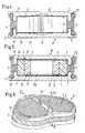
- Fig. 1shows a schematic representation of a preferred Embodiment of an inventive artificial disc B.
- a disc 3in the radial direction under bias braced.
- the height H of the disc 3 of the preferred embodiment from Fig. 1decreases in the radial direction from the outside inwards, wherein However, the height H even in the unloaded state at the edge between X1, X2 initially remains constant.
- the distance from X1 to X2depends on the size of the shear modulus of the disk near X1.
- the shear modulus of Disk 3increases in the radial direction from the outside inwards.
- the stiffnesscorresponds to the slope of the Curve of Fig. 8.
- a higher stiffnesscorresponds to a steeper slope the curve.
- the initial slope of the curvehas a positive, non-zero value. That means, the Inventive artificial disc B shows already at arbitrarily smaller Compression force F and thus at arbitrarily small loads, one certain initial stiffness that is different from zero. It can the Height of the artificial disc B either be constant or e.g.
- the height H of the disc 3is e.g. from anterior to decreases posteriorly or the thickness of the end plates 1, 2 varies accordingly. This can be achieved, among other things, that the elastic behavior the artificial disc B with respect to flexion and Extension movements is not symmetrical.
- the artificialshows Intervertebral disc B also with corresponding arbitrarily small deflections the unloaded state, against torsional and flexion movements a certain initial stiffness. Because the mentioned initial stiffness is achieved in that the disc 3 in the unloaded state on the Fiber ring 4 is under a certain compressive prestress results in the Possibility of observing a given geometry for the artificial disc B and without modification or replacement of the artificial disc B constituent materials, the elastic To adapt properties to the individual needs of a patient. So can the non-linear load characteristics and thus the stiffness and the change thereof with increasing compression force F e.g. to the Body weight of the patient be adjusted by simply by a suitable choice of compression bias according to the requirements, the be individually defined by the physique of the patient, adjusted become.
- the non-linear properties of the disc 3 with respect to a Compression force Fare essentially due to the combination of two Features achieved. First, it increases with increasing Compression S the contact surface 90, 100 between the disc. 3 and the end plate 1, 2. Second, the shear modulus of the disc 3 increases radial direction in such a way that the rigidity of the artificial Intervertebral disc becomes larger with increasing compression.
- the Characteristic of the elastic behavioras shown by way of example in FIG also on the geometry of the disc 3, e.g. by variation of Width of the area between X1 and X2, to be set. Also through a suitable choice of the materials from which the disc is made, the non-linear properties of the disc 3 can be adjusted.
- the disc 3may be made of silicone elastomers or Rubber materials such as e.g. Polycarbourethan (PCU) be constructed. Such Materials can be sprayed to produce the disc 3 and in the different areas of the disc 3 different degrees nachverpresst be, whereby in the disc 3 areas of different stiffness can be generated.
- PCUPolycarbourethan
- Another possibilityis the non-linear behavior
- the disc 3as shown in Fig. 5 so from effective interconnected ring parts 7, 8th be constructed so that the ring parts 7, 8 enclose a cavity 18.
- formation of the cavity 18is by no means absolutely necessary. i.e. the cavity 18 may also be missing.
- FIGS. 1, 4, 5show a particularly high stability with respect to tipping loads, while the Variants shown in Figs. 2 and 3, a larger Can have bending elasticity.
- a larger Canhave bending elasticity.
- Figs. 9 to 12 and Figs. 15 to 17is schematically a Groove 11, 12 shown in the end plate 1, 2, in which the fiber ring 4 is fixed.
- the type of attachmentdepends inter alia on the material of the end plate 1, 2 from.
- the fiber ring 4, as shown in FIGS. 9, 10, on the end plate 1, 2, which is made of metal or plastic, e.g. by an annular Clamping element 13 in the groove 11, 12are fixed and / or in addition (see Fig. 11, 12) in the groove 11, 12 glued.
- Another essential pointis the anchoring of the artificial Intervertebral disc B in the human spine at an adjacent Whirl W (see Fig. 7). So can an improvement of anchoring between end plate 1, 2 and adjacent vortex W with respect to lateral forces by one or more projecting ribs 16, e.g. from ventrally to dorsally, be significantly improved.
- An additional toothing 17 on the outer edge of the cover plate 1, 2also improves the connection between cover and whirl, especially in relation to Shear stresses.
- Zones of metal meshpreferably of titanium or titanium alloys, be attached to the ingrowth of bone material on the vertebrae facilitate or transport.
Landscapes
- Health & Medical Sciences (AREA)
- Engineering & Computer Science (AREA)
- Biomedical Technology (AREA)
- Neurology (AREA)
- Orthopedic Medicine & Surgery (AREA)
- Cardiology (AREA)
- Oral & Maxillofacial Surgery (AREA)
- Transplantation (AREA)
- Heart & Thoracic Surgery (AREA)
- Vascular Medicine (AREA)
- Life Sciences & Earth Sciences (AREA)
- Animal Behavior & Ethology (AREA)
- General Health & Medical Sciences (AREA)
- Public Health (AREA)
- Veterinary Medicine (AREA)
- Prostheses (AREA)
- Magnetic Bearings And Hydrostatic Bearings (AREA)
Abstract
Description
Translated fromGermanDie Erfindung betrifft eine künstliche Bandscheibe gemäss dem Oberbegriffdes unabhängigen Anspruchs 1.The invention relates to an artificial intervertebral disc according to the preambleof
Die Bandscheibe übernimmt in der Wirbelsäule gleich mehrere zentraleFunktionen. Sie wirkt als Dämpfer, Abstandskörper und auch als Gelenkzwischen den Wirbelkörpern. Entsprechend vielschichtig sind dieAnforderungen, die an ein Implantat zu stellen sind, das in seiner Funktion alskünstliche Bandscheibe als Ersatz für eine natürliche Bandscheibe dienensoll. So muss die künstliche Bandscheibe selbstverständlich ausbiokompatiblen Materialen aufgebaut sein und als Dauerimplantat für denPatienten möglichst lebenslang ihre Funktion erfüllen. Neben der einfachenFunktion als Abstandskörper muss die künstliche Bandscheibe insbesonderedie in der Wirbelsäule auftretenden Stosskräfte wirksam abfedern können,damit die Wirbel nicht überlastet werden, ohne dabei jedoch dieWirbelbeweglichkeit merklich zu behindern. Um die natürlichen Dreh-, KippundSchubbelastungen, wie sie in der Wirbelsäule typischerweise auftreten,geeignet ableiten zu können, muss eine feste Verbindung zwischen derkünstlichen Bandscheibe und angrenzendem Wirbel gewährleistet sein.The disc takes over in the spine equal to several centralFunctions. It acts as a damper, spacer and also as a jointbetween the vertebral bodies. Accordingly complex are theRequirements to be met by an implant which, in its function as aartificial disc serving as a replacement for a natural discshould. Of course, the artificial disc must look like thisbiocompatible materials and as a permanent implant for thePatients fulfill their function as lifelong as possible. In addition to the simpleFunction as a spacer body must be the artificial intervertebral disc in particularthe impact forces occurring in the spine can effectively cushionso that the vortices are not overloaded, but without theNoticeably hinder whirl mobility. To the natural turning, tilting andShear loads, as they typically occur in the spine,To be able to derive a firm connection between thebe guaranteed artificial disc and adjacent vertebrae.
Insbesondere an die elastischen Eigenschaften der künstlichen Bandscheibe,sowohl was deren Verhalten bzgl. Torsions- und Schubbelastungen, als auchin Bezug auf Druckbelastungen angeht, sind somit höchste Anforderungen zustellen. Insgesamt bedeutet das, dass die mechanischen Eigenschaften derkünstlichen Bandscheibe möglichst identisch derjenigen der natürlichenBandscheibe nachzubilden sind.In particular, the elastic properties of the artificial disc,both their behavior regarding torsional and thrust loads, as wellIn terms of pressure loads, so are the highest requirements tooput. Overall, this means that the mechanical properties of theartificial intervertebral disc as identical as possible to that of naturalReproduce intervertebral disc.
Zur Nachahmung der natürlichen Eigenschaften einer Bandscheibe sindzahlreiche Lösungsansätze bekannt. So sind künstliche Bandscheibenbekannt, die aus zwei gegenüber angeordneten Endplatten bestehen, dieüber ein elastisches Stützelement verbunden sind, das die Funktion eineskünstlichen Nucleus übernimmt und mit den Endplatten verklebt ist. Derkünstliche Nucleus kann dabei aus einer Kombination von verschiedenenelastischen Kunststoffen bestehen, die noch eine Ummantelung aufweisenkönnen. Das bisher ungelöste Problem solcher Anordnungen besteht jedochunter anderem darin, die passende, d.h. die natürliche, stark nicht-lineare,Charakteristik einer Bandscheibe im üblichen Belastungsbereich für Druck-,Zug-, Schub-, und Torsionsbeanspruchungen bei einer künstlichenBandscheibe nachzubilden.To mimic the natural properties of an intervertebral discnumerous solutions known. Such are artificial discsknown, which consist of two opposing end plates, theare connected via an elastic support member having the function of aartificial nucleus takes over and is glued to the end plates. Of theartificial nucleus may consist of a combination of differentconsist of elastic plastics, which still have a sheathcan. However, the unsolved problem of such arrangements existsamong other things therein, the appropriate, i. the natural, strongly non-linear,Characteristic of an intervertebral disc in the usual load range for pressure,Tensile, shear, and torsional stresses in an artificialImitate intervertebral disc.
Die Aufgabe der Erfindung ist es daher, eine künstliche Bandscheibevorzuschlagen, welche die komplexen elastischen Eigenschaften einernatürlichen Bandscheibe möglichst exakt nachbildet.The object of the invention is therefore an artificial intervertebral discto propose the complex elastic properties of anatural intervertebral disc as accurately as possible.
Die diese Aufgaben lösende künstliche Bandscheibe ist durch die Merkmaledes unabhängigen Anspruchs 1 gekennzeichnet. Die abhängigen Ansprüchebeziehen sich auf besonders vorteilhafte Ausführungsformen der Erfindung.The artificial disc dissolving these tasks is characterized by the featuresof
Die erfindungsgemässe künstliche Bandscheibe zum Implantieren zwischenzwei Wirbelkörper, umfasst zwei Endplatten und eine elastisch verformbare,zwischen den Endplatten in axialer Richtung unter Vorspannung verspannteScheibe, wobei die Scheibe innerhalb eines rohrförmigen elastischverformbaren Faserrings liegt. Dabei stehen die Endplatten mit dem Faserringin zugfester Verbindung. Die Scheibe bildet eine, mit einer Kompression derkünstlichen Bandscheibe sich vergrössernde Berührungsfläche mit einer derangrenzenden Endplatten und die elastischen Eigenschaften der künstlichenBandscheibe zeigen, mindestens in Bezug auf eine Kompressionskraft, mitzunehmender Verformung ein nicht-lineares Verhalten.The inventive artificial disc for implanting betweentwo vertebral bodies, comprising two end plates and an elastically deformable,tensioned between the end plates in the axial direction under biasDisc, the disc being elastic within a tubulardeformable fiber ring lies. Here are the end plates with the fiber ringin tensile connection. The disc forms one, with a compression ofartificial intervertebral disc enlarging contact surface with one of theadjacent end plates and the elastic properties of the artificialIntervertebral disc, at least with respect to a compressive force, withincreasing deformation a non-linear behavior.
Bei der erfindungsgemässen künstlichen Bandscheibe sind zwei sichgegenüberstehende Endplatten an ihrer Peripherie mittels eines elastischverformbaren Faserrings verbunden, welcher auf die Endplatten imunbelasteten Zustand eine ständige Zugkraft ausübt, so dass die Scheibe, diesich zwischen den beiden Endplatten innerhalb des Faserrings befindet, unterDruckvorspannung steht. Ein wesentlicher Nachteil bekannter künstlicherBandscheiben besteht darin, dass unter der Wirkung einer elastischenDeformation zuviel Weg beansprucht wird, bis der eigentlicheBelastungsbereich erreicht ist. Ein entscheidender Vorteil dererfindungsgemässen künstlichen Bandscheibe ist daher darin zu sehen, dassderen elastisches Verhalten, zumindest in Bezug auf eine Kompression,bereits bei kleinen Deformationen ein nicht-lineares Verhalten zeigt.In the artificial intervertebral disc according to the invention, two are themselvesopposing end plates on their periphery by means of an elasticdeformable fiber ring connected, which on the end plates in theunloaded condition exerts a constant pulling force, so that the disc, theis located between the two end plates within the fiber ring, belowPressure bias is. A major disadvantage of known artificialIntervertebral discs is that under the action of an elasticDeformation is claimed way too much, until the actualLoad range is reached. A decisive advantage ofThe inventive artificial disc is therefore to be seen in thattheir elastic behavior, at least in terms of compression,already shows a non-linear behavior with small deformations.
Das elastische Verhalten der erfindungsgemässen künstlichen Bandscheibeist dabei durch die konstruktiven Besonderheiten von Faserring und Scheibeund der sie umfassenden Materialien, sowie durch die konstruktionsbedingtemechanische Kopplung von Faserring und Scheibe bestimmt. So kann dasmechanische Verhalten des Faserrings bezüglich einer Dehnung unterZugbeanspruchung, sowie einer Dehnung z.B. infolge vonTorsionsbelastungen schon durch die Art des Gewebes verschieden sein, jenachdem ob der Faserring gewebt, gestrickt, geflochten oder auf andereWeise hergestellt wurde. Dabei spielt unter anderem die Orientierung derFasern, aus denen der Faserring aufgebaut ist, in ihrer Schräglage zurRichtung der Längsachse der künstlichen Bandscheibe eine Rolle für diezwischen den Endplatten zu übertragenden Kräften. Während die Scheibealleine, d.h. nicht in Kombination mit dem Faserring, z.B. in Bezug auf reineTorsionsbewegungen lediglich einen Gleitreibungswiderstand bildet, kanndurch die Kombination beider Elemente und eine entgegengesetzteSchrägstellung der Fasern relativ zur Richtung der Längsachse derkünstlichen Bandscheibe, eine Umsetzung z.B. von Torsionsbewegungen ineine Kompression der Scheibe erreicht werden. Dadurch werden die nicht-linearen elastischen Eigenschaften, die die Scheibe bezüglich einerKompression aufweist, in das elastische Torsionsverhalten der künstlichenBandscheibe transformiert. Die Scheibe steht im unbelasteten Zustand überden Faserring unter einer gewissen Druckvorspannung. Damit besteht dieMöglichkeit, unter Einhaltung einer vorgegebenen Geometrie für diekünstlichen Bandscheibe und ohne Veränderung oder Austausch der diekünstliche Bandscheibe aufbauenden Materialien, die elastischenEigenschaften an die individuellen Bedürfnisse eines Patienten anzupassen.So kann die nicht-lineare Belastungscharakteristik z.B. an das Körpergewichtdes Patienten und / oder die Kopplung von Torsionsbelastungen oder anderenBelastungsarten an eine Kompression der Scheibe angepasst werden.The elastic behavior of the inventive artificial discThis is due to the design features of fiber ring and discand the materials that comprise them, as well as the design-relateddetermined mechanical coupling of fiber ring and disc. That's how it worksmechanical behavior of the fiber ring with respect to a strain underTensile stress, as well as elongation e.g. as a consequence ofTorsion loads may be different depending on the type of tissue, dependingafter whether the fiber ring woven, knitted, braided or on othersWay was made. Among other things, the orientation of theFibers from which the fiber ring is constructed, in their oblique position toDirection of the longitudinal axis of the artificial disc a role for thebetween the end plates to be transmitted forces. While the discalone, i. not in combination with the fiber ring, e.g. in terms of pureTorsionsbewegungen forms only a sliding friction, canby the combination of both elements and an opposite oneInclination of the fibers relative to the direction of the longitudinal axis of theartificial disc, an implementation e.g. of torsional movements ina compression of the disc can be achieved. This will make the non-linearelastic properties that the disc relative to aCompression, in the elastic torsional behavior of the artificialIntervertebral disc transformed. The disc is over in the unloaded statethe fiber ring under a certain pressure bias. This is thePossibility of observing a given geometry for theartificial intervertebral disc and without change or replacement of theartificial disc constructing materials, the elasticTo adapt properties to the individual needs of a patient.Thus, the non-linear load characteristic may be e.g. to the body weightof the patient and / or the coupling of torsional loads or othersTypes of load can be adapted to a compression of the disc.
Die Art der Konstruktion mit einem auf Zug beanspruchten Faserring undeiner auf Druck beanspruchten Scheibe gestattet es, die Vorspannungzwischen diesen beiden Elementen im unbelasteten Zustand so hoch zuwählen, dass bei extremer Druckbelastung immer noch eine Restspannung inZugrichtung vorhanden ist, die bei einer Begrenzung von zusätzlichen ScherundTorsionsbelastungen mitwirkt. Darüber hinaus kann man (z.B. durch dieGeometrie der Scheibe in Kombination mit einer geeigneten Wahl derVorspannung des Faserrings) es erreichen, dass die künstliche Bandscheibefür kleine Belastungen bezüglich Kipp- und Biegebewegungen eine gewisseelastische Neutralzone aufweist.The nature of the construction with a claimed on train fiber ring anda pressure-loaded disc allows the preloadbetween these two elements in the unloaded state so highchoose that under extreme pressure load still a residual stress inZugrichtung is present, which at a limit of additional shear andTorsion loads participates. In addition one can (for example by theGeometry of the disc in combination with a suitable choice ofBiasing the fiber ring) it will reach that artificial discfor small loads with respect to tilting and bending movements a certainhaving elastic neutral zone.
Die den Faserring aufbauenden Materialien umfassen, soweit sie mitKörpergewebe in Berührung kommen, körperverträgliche Kunststoffe. DerFaserring selbst kann durchlässig für körpereigene Flüssigkeiten sein. DieEndplatten können aus einem Metall, beispielsweise aus zähfestem Titanoder aus einer zähfesten Titanlegierung gefertigt sein, welche für dieVerankerung des Faserrings plastisch deformierbar ist. Die Aussenflächen derEndplatten können Zonen mit Metallgewebe aufweisen, die das Einwachsenvon Knochenmaterial, und damit das Verwachsen der angrenzenden Wirbel mit den äusseren Flächen der Endplatten erleichtern. Eine Verbesserung derVerankerung zwischen Endplatte und Wirbel bezüglich Seitenkräften wirddurch eine oder mehrere vorstehende Rippen erreicht, die beispielsweise vonventral nach dorsal verlaufen können. Eine zusätzliche Zahnung amAussenrand der Endplatte, die, ebenso wie die vorstehende Rippe, nichtzwingend vorhanden sein muss, kann ebenfalls die Verbindung zwischenEndplatte und Wirbel bezüglich Scherbeanspruchungen deutlich verbessern.Dabei muss die Endplatte nicht unbedingt aus Metall aufgebaut sein, sondernes können beispielsweise auch geeignete körperverträgliche Kunststoffe alsMaterialien für den Aufbau der Endplatte in Betracht kommen.The materials constituting the fiber ring include, as far as they are concernedBody tissues come into contact, biocompatible plastics. Of theFiber ring itself can be permeable to the body's fluids. TheEnd plates can be made of a metal, for example made of tough titaniumor be made of a tough titanium alloy, which for theAnchoring the fiber ring is plastically deformable. The exterior surfaces of theEndplates may have zones of metal mesh that are ingrowthof bone material, and thus the ingrowth of the adjacent vertebraefacilitate with the outer surfaces of the end plates. An improvement in theAnchoring between the end plate and the vertebra with respect to lateral forcesachieved by one or more projecting ribs, for example, fromventral to dorsally. An additional toothing on theOutside edge of the end plate, which, as well as the protruding rib, notMandatory, can also be the connection betweenEnd plate and vortex significantly improve shear stress.The end plate does not necessarily have to be made of metal, but ratherFor example, suitable biocompatible plastics can be used as wellMaterials for the construction of the end plate come into consideration.
Im folgenden wird die Erfindung anhand von bevorzugtenAusführungsbeispielen, sowie der Zeichnung näher erläutert. Es zeigen:
- Fig. 1
- Schematisch einen Längsschnitt durch eine erste Variante einererfindungsgemässen künstliche Bandscheibe;
- Fig. 2
- eine zweite Variante des Ausführungsbeispiels gemäss Fig. 1;
- Fig. 3
- eine dritte Variante des Ausführungsbeispiels gemäss Fig. 1
- Fig. 4
- eine vierte Variante des Ausführungsbeispiels gemäss Fig. 1
- Fig. 5
- eine andere Variante des Ausführungsbeispiels gemäss Fig. 1
- Fig. 6
- schematisch eine Ansicht gemäss den
Figuren 1 bis 5; - Fig. 7
- eine erfindungsgemässe künstliche Bandscheibe gemäss den
Figuren 1 bis 6, eingesetzt zwischen zwei Wirbel; - Fig. 8
- Kraft - Weg Diagramm des elastischen Verhaltens einererfindungsgemässen künstlichen Bandscheibe;
- Fig. 9
- ein Ausführungsbeispiel zur Verbindung des Faserrings mit einerEndplatte mittels eines ringförmigen Klemmelementes;
- Fig. 10
- eine zweite Variante eines Ausführungsbeispiels gemäss Fig. 9;
- Fig. 11
- eine dritte Variante eines Ausführungsbeispiels gemäss Fig. 9,wobei der Faserring zusätzlich verklebt oder verschweisst ist;
- Fig. 12
- ein Ausführungsbeispiel zur Verbindung des Faserrings mit einerEndplatte, wobei der Faserring verklebt, verschweisst oderangespritzt ist;
- Fig. 13
- ein Ausführungsbeispiel zur Verbindung des Faserrings mit einerEndplatte, wobei der Faserring durch ein Halteelement fixiert ist;
- Fig. 14
- ein weiteres Ausführungsbeispiel gemäss Fig. 13;
- Fig. 15
- ein Ausführungsbeispiel zur Verbindung des Faserrings mit einerEndplatte, wobei der Faserring in einer Nut kalt verpresst ist;
- Fig. 16
- ein zweites Ausführungsbeispiel gemäss Fig. 15;
- Fig. 17
- ein drittes Ausführungsbeispiel gemäss Fig. 15.
- Fig. 1
- Schematically a longitudinal section through a first variant of an inventive artificial disc;
- Fig. 2
- a second variant of the embodiment of FIG. 1;
- Fig. 3
- a third variant of the embodiment according to FIG. 1
- Fig. 4
- A fourth variant of the embodiment according to FIG. 1
- Fig. 5
- another variant of the embodiment according to FIG. 1
- Fig. 6
- schematically a view according to Figures 1 to 5;
- Fig. 7
- an inventive artificial disc according to the invention shown in FIGS. 1 to 6, inserted between two vertebrae;
- Fig. 8
- Force-displacement diagram of the elastic behavior of an artificial intervertebral disc according to the invention;
- Fig. 9
- an embodiment for connecting the fiber ring with an end plate by means of an annular clamping element;
- Fig. 10
- a second variant of an embodiment according to FIG. 9;
- Fig. 11
- a third variant of an embodiment according to FIG 9, wherein the fiber ring is additionally glued or welded;
- Fig. 12
- an embodiment for connecting the fiber ring with an end plate, wherein the fiber ring is glued, welded or molded;
- Fig. 13
- an embodiment for connecting the fiber ring with an end plate, wherein the fiber ring is fixed by a holding member;
- Fig. 14
- a further embodiment according to FIG. 13;
- Fig. 15
- an embodiment for connecting the fiber ring with an end plate, wherein the fiber ring is cold pressed in a groove;
- Fig. 16
- a second embodiment of FIG. 15;
- Fig. 17
- A third embodiment according to FIG. 15.
Die Erfindung wird im folgenden anhand bevorzugter Ausführungsbeispieleerläutert. Die erfindungsgemässe künstliche Bandscheibe B umfasst zweiEndplatten 1, 2, zwischen welchen mittels eines Faserrings 4 eine Scheibe 3unter Vorspannung in axialer Richtung verspannt ist, wodurch die Endplatten1, 2 in zugfester Verbindung stehen. Dabei weist die Scheibe 3 unterDruckbelastung eine sich vergrössernde Berührungsfläche 5, 6 mit einer derangrenzenden Endplatten 1, 2 auf. Die elastischen Eigenschaften derkünstlichen Bandscheibe B zeigen dabei mindestens in Bezug auf eine Kompressionskraft F ein mit zunehmender Deformation S nicht linearesVerhalten.The invention will be described below with reference to preferred embodimentsexplained. The inventive artificial disc B comprises two
Fig. 1 zeigt in einer schematischen Darstellung ein bevorzugtesAusführungsbeispiel einer erfindungsgemässen künstlichen Bandscheibe B.Zwischen den Endplatten 1, 2, deren Innenseiten 90, 100 als plane Flächenausgebildet sind, ist eine Scheibe 3 in radialer Richtung unter Vorspannungverspannt. Die Höhe H der Scheibe 3 des bevorzugten Ausführungsbeispielsaus Fig. 1 verringert sich in radialer Richtung von aussen nach innen, wobeijedoch die Höhe H auch im unbelasteten Zustand am Rand zwischen X1, X2zunächst konstant bleibt. Der Abstand von X1 zu X2 hängt von der Grössedes Schubmoduls der Scheibe in der Nähe von X1 ab. Der Schubmodul derScheibe 3 nimmt dabei in radialer Richtung von aussen nach innen zu. Untereiner Kompressionskraft F, die senkrecht zu den Flächen 1, 2 auf diekünstliche Bandscheibe B wirkt, wird die elastische Scheibe 3 komprimiert,wobei sich die Berührungsfläche 5, 6 zwischen Scheibe 3 und Innenfläche 90,100 der Deckplatte 1, 2 vergrössert. Da der Schubmodul der Scheibe 3 vonaussen nach innen in radialer Richtung anwächst, erhöht sich mitzunehmender Kompression insgesamt die Steifigkeit der künstlichenBandscheibe B. Dieses Verhalten zeigt Fig. 8, in der exemplarisch in Formeines Kraft-Weg Diagramms die Deformation S einer erfindungsgemässenkünstlichen Bandscheibe B unter einer Kompressionskraft F aufgetragen ist.Wobei eine grössere Steifigkeit bedeutet, dass für eine bestimmte festvorgegebene Deformation S der künstlichen Bandscheibe B eine grössereKraft F benötigt wird, als für eine gleiche Deformation S bei einer kleinerenSteifigkeit. Das heisst, die Steifigkeit korrespondiert mit der Steigung derKurve aus Fig. 8. Eine höhere Steifigkeit entspricht einem steileren Anstiegder Kurve. So liegt beispielsweise die Steifigkeit der erfindungsgemässenkünstlichen Bandscheibe unter einer Kompressionskraft F von ca. 2500 N ineinem Bereich zwischen 1700 N/mm und 4500 N/mm. Es ist ein besonderesCharaktersitikum des Kraft-Weg Diagramms in Fig. 8, dass, analog zum Verhalten einer natürlichen Bandscheibe, die Anfangssteigung der Kurveeinen positiven, von Null verschiedenen Wert hat. Das heisst, dieerfindungsgemässe künstliche Bandscheibe B zeigt bereits bei beliebig kleinerKompressionskraft F und damit bei beliebig kleinen Belastungen, einegewisse Anfangssteifigkeit, die von Null verschieden ist. Dabei kann dieBauhöhe der künstlichen Bandscheibe B entweder konstant sein oder z.B.von anterior nach posterior abnehmen. Das kann beispielweise dadurchrealisiert werden, dass die Höhe H der Scheibe 3 z.B. von anterior nachposterior abnimmt oder die Dicke der Endplatten 1, 2 entsprechend variiert.Dadurch kann unter anderem erreicht werden, dass das elastische Verhaltender künstlichen Bandscheibe B bezüglich Flexions- undExtensionsbewegungen nicht symmetrisch ist.Fig. 1 shows a schematic representation of a preferredEmbodiment of an inventive artificial disc B.Between the
Da die nicht-linearen Eigenschaften der Scheibe 3, die diese bezüglich einerKompressionskraft F aufweist, durch den Faserring 4 in das elastischeTorsions- und Flexionsverhalten transformiert werden, zeigt die künstlicheBandscheibe B auch bei entsprechenden beliebig kleinen Auslenkungen ausdem unbelasteten Zustand, gegenüber Torsions- und Flexionsbewegungeneine bestimmte Anfangssteifigkeit. Da die erwähnte Anfangssteifigkeitdadurch erreicht wird, dass die Scheibe 3 im unbelasteten Zustand über denFaserring 4 unter einer gewissen Druckvorspannung steht, ergibt sich dieMöglichkeit, unter Einhaltung einer vorgegebenen Geometrie für diekünstlichen Bandscheibe B und ohne Veränderung oder Austausch der diekünstliche Bandscheibe B aufbauenden Materialien, die elastischenEigenschaften an die individuellen Bedürfnisse eines Patienten anzupassen.So kann die nicht-lineare Belastungscharakteristik und damit die Steifigkeitund deren Veränderung mit zunehmender Kompressionskraft F z.B. an dasKörpergewicht des Patienten angepasst werden, indem einfach durch einegeeignete Wahl der Druckvorspannung entsprechend den Anforderungen, diedurch den Körperbau des Patienten individuell definiert werden, angepasstwerden.Since the non-linear properties of the
Die nicht-linearen Eigenschaften der Scheibe 3 bezüglich einerKompressionskraft F werden im wesentlichen durch die Kombination zweierMerkmale erreicht. Erstens vergrössert sich mit zunehmendemKompressionsweg S die Berührungsfläche 90, 100 zwischen der Scheibe 3und der Endplatte 1, 2. Zweitens nimmt der Schubmodul der Scheibe 3 inradialer Richtung in der Weise zu, dass die Steifigkeit der künstlichenBandscheibe mit zunehmender Kompression grösser wird. Somit kann dieCharakteristik des elastischen Verhaltens, wie es in Figur 8 exemplarischgezeigt wird, auch über die Geometrie der Scheibe 3, z.B. durch Variation derBreite des Bereiches zwischen X1 und X2, festgelegt werden. Auch durcheine geeignete Wahl der Materialien, aus denen die Scheibe aufgebaut wird,lassen sich die nicht-linearen Eigenschaften der Scheibe 3 einstellen. Darüberhinaus kann die Stärke der Zunahme des Schubmoduls der Scheibe 3 inradialer Richtung auf verschiedene Weisen festgelegt bzw. variiert werden.Die Scheibe 3 kann zum Beispiel aus Silikonelastomeren oderGummimaterialien wie z.B. Polycarbourethan (PCU) aufgebaut sein. SolcheMaterialen können zur Herstellung der Scheibe 3 angespritzt und in denverschiedenen Bereichen der Scheibe 3 unterschiedlich stark nachverpresstwerden, wodurch in der Scheibe 3 Bereiche unterschiedlicher Steifigkeiterzeugt werden können. Eine andere Möglichkeit das nicht-lineare Verhaltender Scheibe 3 zu modellieren besteht darin, die Scheibe 3 konzentrisch auswirkfest miteinander verbundenen Ringen verschiedener Materialien, dieunterschiedliche Steifigkeit aufweisen, aufzubauen. Dabei kann die Scheibe 3wie in Fig. 5 gezeigt so aus wirkfest miteinander verbundenen Ringteilen 7, 8aufgebaut sein, dass die Ringeteile 7, 8 einen Hohlraum 18 umschliessen. DieBildung des Hohlraumes 18 ist jedoch in keiner Weise zwingend erforderlich,d.h. der Hohlraum 18 kann auch fehlen.The non-linear properties of the
Für die Bildung der sich unter einer Kompressionskraft F vergrösserndeFläche 5, 6 sind verschiedene Varianten denkbar. So kann die nach innengewandte Fläche 90, 100 der Endplatte 1, 2 wie in den Fig. 1, 2, 5 gezeigt, eine im wesentlichen plane Oberfläche aufzeigen. Die Höhe H der Scheibe 3verringert sich dann in radialer Richtung entweder von aussen nach innen(siehe Fig. 1 und Fig 5) oder von innen nach aussen (siehe Fig 2), wobei dieHöhe H auch im unbelasteten Zustand über den Bereich zwischen X1 und X2konstant bleibt. Weitere Varianten werden in den Fig. 3 und 4 gezeigt. Beidiesen Varianten des bevorzugten Ausführungsbeispiels ist die Höhe H derScheibe 3 konstant. Stattdessen variiert der Abstand der Deckplatte 1, 2 zurScheibe 3 in radialer Richtung entweder von innen nach aussen oderumgekehrt. Dabei zeigen die in den Fig. 1, 4, 5 gezeigten Varianten einebesonders hohe Stabilität in Bezug auf Kippbelastungen, während dieVarianten, die in den Fig. 2 und 3 gezeigt werden, eine grössereBiegeelastizität haben können. Selbstverständlich sind auch geeigneteKombinationen der zuvor beschriebenen Ausführungsbeispiele denkbar.For formation of increasing under a compression
Voraussetzung für eine gute Funktion der erfindungsgemässen künstlichenBandscheibe ist eine einwandfreie Verankerung des Faserrings 4 in derEndplatte 1, 2. In den Fig. 9 bis 12 und den Fig. 15 bis 17 ist schematisch eineNut 11, 12 in der Endplatte 1, 2 gezeigt, in der der Faserring 4 befestigt ist.Die Art der Befestigung hängt unter anderem vom Material der Endplatte 1, 2ab. So kann der Faserring 4, wie in den Fig. 9, 10 gezeigt, an der Endplatte 1,2, die aus Metall oder Kunststoff gefertigt ist, z.B. durch ein ringförmigesKlemmelement 13 in der Nut 11, 12 fixiert werden und / oder zusätzlich (sieheFig. 11, 12) in der Nut 11, 12 verklebt sein. Bei der Endplatte 1, 2 ausKunststoff ist alternativ zum Kleben auch thermisches Verschweissen in derNut 11, 12 oder auf einer Oberfläche der Endplatte 1, 2 möglich. Bei einermetallischen Endplatte 1, 2 kann der Faserring 4 durch Kaltumformung V inder Nut 11, 12 verpresst werden. Dabei kann die Nut 11, 12 wie in den Fig. 15bis 17 gezeigt unter einem bestimmten Winkel α gegen die Oberfläche derEndplatte 1, 2 geneigt sein. Dabei wird ein Winkel α gewählt, der zwischen 0Grad (Fig. 17) und 90 Grad (Fig. 15), vorzugsweise jedoch in der Nähe von 30Grad liegt. Als weitere Variante für die Befestigung des Faserrings 4 an der Endplatte 1, 2 ist auch eine Fixierung mittels eines zusätzlichenHalteelementes 14 denkbar, das zum Beispiel als Platte (Fig. 13) oder alsRing (Fig. 14) ausgebildet sein kann und vorzugsweise mittels einerVerschraubung 15 an der Endplatte 1, 2 befestigt ist.Prerequisite for a good function of the inventive artificialIntervertebral disc is a perfect anchorage of the
Ein weiterer wesentlicher Punkt ist die Verankerung der künstlichenBandscheibe B in der menschlichen Wirbelsäule an einem angrenzendenWirbel W (siehe Fig. 7). So kann eine Verbesserung der Verankerungzwischen Endplatte 1, 2 und angrenzendem Wirbel W bezüglich Seitenkräftendurch eine oder mehrere vorstehende Rippen 16, die z.B. von ventral nachdorsal verlaufen, wesentlich verbessert werden. Eine zusätzliche Zahnung 17am Aussenrand der Deckplatte 1, 2 verbessert ebenfalls die Verbindungzwischen Deckel und Wirbel, insbesondere in Bezug aufScherbeanspruchungen. Auf den Aussenseiten der Endplatten 1, 2 könnenZonen aus Metallgeflechten, vorzugsweise aus Titan oder Titanlegierungen,aufgebracht sein, die das Einwachsen von Knochenmaterial an den Wirbelnerleichtern bzw. befördern.Another essential point is the anchoring of the artificialIntervertebral disc B in the human spine at an adjacentWhirl W (see Fig. 7). So can an improvement of anchoringbetween
Claims (19)
Translated fromGermanPriority Applications (4)
| Application Number | Priority Date | Filing Date | Title |
|---|---|---|---|
| EP01810827AEP1287794B1 (en) | 2001-08-24 | 2001-08-24 | Artificial spinal disc |
| AT01810827TATE398430T1 (en) | 2001-08-24 | 2001-08-24 | ARTIFICIAL DISC |
| DE50114037TDE50114037D1 (en) | 2001-08-24 | 2001-08-24 | Artificial disc |
| US10/226,517US6626943B2 (en) | 2001-08-24 | 2002-08-23 | Artificial intervertebral disc |
Applications Claiming Priority (1)
| Application Number | Priority Date | Filing Date | Title |
|---|---|---|---|
| EP01810827AEP1287794B1 (en) | 2001-08-24 | 2001-08-24 | Artificial spinal disc |
Publications (2)
| Publication Number | Publication Date |
|---|---|
| EP1287794A1true EP1287794A1 (en) | 2003-03-05 |
| EP1287794B1 EP1287794B1 (en) | 2008-06-18 |
Family
ID=8184108
Family Applications (1)
| Application Number | Title | Priority Date | Filing Date |
|---|---|---|---|
| EP01810827AExpired - LifetimeEP1287794B1 (en) | 2001-08-24 | 2001-08-24 | Artificial spinal disc |
Country Status (4)
| Country | Link |
|---|---|
| US (1) | US6626943B2 (en) |
| EP (1) | EP1287794B1 (en) |
| AT (1) | ATE398430T1 (en) |
| DE (1) | DE50114037D1 (en) |
Cited By (6)
| Publication number | Priority date | Publication date | Assignee | Title |
|---|---|---|---|---|
| WO2006004848A1 (en) | 2004-06-30 | 2006-01-12 | Synergy Disc Replacement, Inc. | Artificial spinal disc |
| DE102004041354A1 (en)* | 2004-08-25 | 2006-03-30 | Buck, Alfred | Implant for surgical use in humans or vertebrates |
| DE102005025685A1 (en)* | 2005-06-03 | 2006-12-14 | Mathys Ag Bettlach | Intervertebral disc implant |
| FR2894808A1 (en)* | 2005-12-20 | 2007-06-22 | Spineart Sa Sa | ANATOMICAL DISC DISC SPACER AND ITS APPLICATIONS |
| WO2007090017A1 (en)* | 2006-01-27 | 2007-08-09 | Warsaw Orthopedic, Inc. | Intervertebral implants and methods of use |
| WO2013055723A1 (en)* | 2011-10-10 | 2013-04-18 | Synthes Gmbh | Implant with compliant layer |
Families Citing this family (247)
| Publication number | Priority date | Publication date | Assignee | Title |
|---|---|---|---|---|
| US20050245937A1 (en)* | 2004-04-28 | 2005-11-03 | St. Francis Medical Technologies, Inc. | System and method for insertion of an interspinous process implant that is rotatable in order to retain the implant relative to the spinous processes |
| US7201751B2 (en)* | 1997-01-02 | 2007-04-10 | St. Francis Medical Technologies, Inc. | Supplemental spine fixation device |
| US20080086212A1 (en)* | 1997-01-02 | 2008-04-10 | St. Francis Medical Technologies, Inc. | Spine distraction implant |
| US20080039859A1 (en)* | 1997-01-02 | 2008-02-14 | Zucherman James F | Spine distraction implant and method |
| US6068630A (en)* | 1997-01-02 | 2000-05-30 | St. Francis Medical Technologies, Inc. | Spine distraction implant |
| US7306628B2 (en)* | 2002-10-29 | 2007-12-11 | St. Francis Medical Technologies | Interspinous process apparatus and method with a selectably expandable spacer |
| US7959652B2 (en)* | 2005-04-18 | 2011-06-14 | Kyphon Sarl | Interspinous process implant having deployable wings and method of implantation |
| US6936071B1 (en) | 1999-07-02 | 2005-08-30 | Spine Solutions, Inc. | Intervertebral implant |
| US20040172019A1 (en)* | 1999-10-08 | 2004-09-02 | Ferree Bret A. | Reinforcers for artificial disc replacement methods and apparatus |
| US7717958B2 (en)* | 2000-02-16 | 2010-05-18 | Trans1, Inc. | Prosthetic nucleus apparatus |
| US7938836B2 (en)* | 2003-10-23 | 2011-05-10 | Trans1, Inc. | Driver assembly for simultaneous axial delivery of spinal implants |
| US7776068B2 (en)* | 2003-10-23 | 2010-08-17 | Trans1 Inc. | Spinal motion preservation assemblies |
| US7601171B2 (en)* | 2003-10-23 | 2009-10-13 | Trans1 Inc. | Spinal motion preservation assemblies |
| US7267687B2 (en)* | 2001-10-02 | 2007-09-11 | Rex Medical, L.P | Spinal implant and method of use |
| FR2832917B1 (en)* | 2001-11-30 | 2004-09-24 | Spine Next Sa | ELASTICALLY DEFORMABLE INTERVERTEBRAL IMPLANT |
| US8696749B2 (en)* | 2002-04-25 | 2014-04-15 | Blackstone Medical, Inc. | Artificial intervertebral disc |
| US6960232B2 (en)* | 2002-04-25 | 2005-11-01 | Blackstone Medical, Inc. | Artificial intervertebral disc |
| US6793678B2 (en) | 2002-06-27 | 2004-09-21 | Depuy Acromed, Inc. | Prosthetic intervertebral motion disc having dampening |
| EP1542626B1 (en) | 2002-08-15 | 2012-09-26 | Synthes GmbH | Controlled artificial intervertebral disc implant |
| CA2495404C (en) | 2002-08-15 | 2011-05-03 | Justin K. Coppes | Intervertebral disc implant |
| FR2844179B1 (en)* | 2002-09-10 | 2004-12-03 | Jean Taylor | POSTERIOR VERTEBRAL SUPPORT KIT |
| US7931674B2 (en) | 2005-03-21 | 2011-04-26 | Kyphon Sarl | Interspinous process implant having deployable wing and method of implantation |
| US20060264939A1 (en)* | 2003-05-22 | 2006-11-23 | St. Francis Medical Technologies, Inc. | Interspinous process implant with slide-in distraction piece and method of implantation |
| US8070778B2 (en)* | 2003-05-22 | 2011-12-06 | Kyphon Sarl | Interspinous process implant with slide-in distraction piece and method of implantation |
| US8147548B2 (en)* | 2005-03-21 | 2012-04-03 | Kyphon Sarl | Interspinous process implant having a thread-shaped wing and method of implantation |
| US8048117B2 (en) | 2003-05-22 | 2011-11-01 | Kyphon Sarl | Interspinous process implant and method of implantation |
| US7549999B2 (en) | 2003-05-22 | 2009-06-23 | Kyphon Sarl | Interspinous process distraction implant and method of implantation |
| US20080021468A1 (en)* | 2002-10-29 | 2008-01-24 | Zucherman James F | Interspinous process implants and methods of use |
| US7909853B2 (en)* | 2004-09-23 | 2011-03-22 | Kyphon Sarl | Interspinous process implant including a binder and method of implantation |
| US20040093087A1 (en)* | 2002-11-05 | 2004-05-13 | Ferree Bret A. | Fluid-filled artificial disc replacement (ADR) |
| US7776042B2 (en) | 2002-12-03 | 2010-08-17 | Trans1 Inc. | Methods and apparatus for provision of therapy to adjacent motion segments |
| US7335203B2 (en)* | 2003-02-12 | 2008-02-26 | Kyphon Inc. | System and method for immobilizing adjacent spinous processes |
| AU2004212942A1 (en) | 2003-02-14 | 2004-09-02 | Depuy Spine, Inc. | In-situ formed intervertebral fusion device |
| EP1605872B1 (en)* | 2003-03-24 | 2009-09-30 | Synthes GmbH | Vertebral disc or intervertebral disc prosthesis |
| US7563281B2 (en)* | 2003-04-03 | 2009-07-21 | Warsaw Orthopedic, Inc. | Apparatus and method for supporting vertebral bodies |
| EP1610740A4 (en) | 2003-04-04 | 2009-04-08 | Theken Disc Llc | Artificial disc prosthesis |
| CN100484499C (en)* | 2003-04-14 | 2009-05-06 | 斯恩蒂斯有限公司 | Intervertebral implant |
| US6981989B1 (en)* | 2003-04-22 | 2006-01-03 | X-Pantu-Flex Drd Limited Liability Company | Rotatable and reversibly expandable spinal hydraulic prosthetic device |
| US7491204B2 (en) | 2003-04-28 | 2009-02-17 | Spine Solutions, Inc. | Instruments and method for preparing an intervertebral space for receiving an artificial disc implant |
| US7105024B2 (en) | 2003-05-06 | 2006-09-12 | Aesculap Ii, Inc. | Artificial intervertebral disc |
| US7291173B2 (en) | 2003-05-06 | 2007-11-06 | Aesculap Ii, Inc. | Artificial intervertebral disc |
| DE10324108B3 (en)* | 2003-05-21 | 2005-01-27 | Aesculap Ag & Co. Kg | Backbone implant is inserted with contracted contact disc which is expanded to optimum area following insertion |
| US7537612B2 (en)* | 2003-06-20 | 2009-05-26 | Warsaw Orthopedic, Inc. | Lumbar composite nucleus |
| US7008452B2 (en)* | 2003-06-26 | 2006-03-07 | Depuy Acromed, Inc. | Dual durometer elastomer artificial disc |
| US20040267367A1 (en) | 2003-06-30 | 2004-12-30 | Depuy Acromed, Inc | Intervertebral implant with conformable endplate |
| DE20310433U1 (en) | 2003-07-08 | 2003-09-04 | Aesculap AG & Co. KG, 78532 Tuttlingen | Surgical device for inserting dual component implant into appropriate space at spine, comprising particularly shaped holding area |
| DE10330698B4 (en) | 2003-07-08 | 2005-05-25 | Aesculap Ag & Co. Kg | Intervertebral implant |
| US7695515B2 (en)* | 2003-07-15 | 2010-04-13 | Spinal Generations, Llc | Spinal disc prosthesis system |
| US20050015150A1 (en)* | 2003-07-17 | 2005-01-20 | Lee Casey K. | Intervertebral disk and nucleus prosthesis |
| US7153325B2 (en)* | 2003-08-01 | 2006-12-26 | Ultra-Kinetics, Inc. | Prosthetic intervertebral disc and methods for using the same |
| DE10339170B4 (en) | 2003-08-22 | 2009-10-15 | Aesculap Ag | Intervertebral implant |
| US7766914B2 (en)* | 2003-09-10 | 2010-08-03 | Warsaw Orthopedic, Inc. | Adjustable drill guide |
| US7794465B2 (en)* | 2003-09-10 | 2010-09-14 | Warsaw Orthopedic, Inc. | Artificial spinal discs and associated implantation instruments and methods |
| US20050085909A1 (en)* | 2003-10-15 | 2005-04-21 | Sdgi Holding, Inc. | Semi-constrained and mobile-bearing disc prosthesis |
| WO2005041816A2 (en)* | 2003-10-20 | 2005-05-12 | Blackstone Medical, Inc. | Vertebral body replacement apparatus and method |
| EP1532950B1 (en)* | 2003-11-18 | 2008-03-26 | Zimmer GmbH | Spinal disc prosthesis |
| WO2005053580A1 (en)* | 2003-11-28 | 2005-06-16 | Richard Mervyn Walker | An intervertebral prosthesis |
| US7250060B2 (en) | 2004-01-27 | 2007-07-31 | Sdgi Holdings, Inc. | Hybrid intervertebral disc system |
| US20050187631A1 (en)* | 2004-01-27 | 2005-08-25 | Sdgi Holdings, Inc. | Prosthetic device |
| EP2113227B1 (en) | 2004-02-04 | 2015-07-29 | LDR Medical | Intervertebral disc prosthesis |
| US8636802B2 (en) | 2004-03-06 | 2014-01-28 | DePuy Synthes Products, LLC | Dynamized interspinal implant |
| US7806933B2 (en)* | 2004-03-15 | 2010-10-05 | Warsaw Orthopedic, Inc. | System and method for stabilizing a prosthetic device |
| DE202004009542U1 (en) | 2004-06-16 | 2004-08-12 | Aesculap Ag & Co. Kg | Artificial intervertebral disk, comprising core with intensely curved upper and less curved lower surface |
| US9237958B2 (en) | 2004-06-30 | 2016-01-19 | Synergy Disc Replacement Inc. | Joint prostheses |
| US8454699B2 (en) | 2004-06-30 | 2013-06-04 | Synergy Disc Replacement, Inc | Systems and methods for vertebral disc replacement |
| US8172904B2 (en) | 2004-06-30 | 2012-05-08 | Synergy Disc Replacement, Inc. | Artificial spinal disc |
| JP2008508980A (en)* | 2004-08-09 | 2008-03-27 | トランス1,インク. | Nucleus nucleus prosthesis device and method |
| US8012209B2 (en)* | 2004-09-23 | 2011-09-06 | Kyphon Sarl | Interspinous process implant including a binder, binder aligner and method of implantation |
| US7780731B2 (en)* | 2004-11-26 | 2010-08-24 | Spine Solutions, Inc. | Intervertebral implant |
| US7763024B2 (en)* | 2004-09-23 | 2010-07-27 | Spine Solutions, Inc. | Adjustable cutting of cutout in vertebral bone |
| AU2006206559A1 (en)* | 2005-01-19 | 2006-07-27 | Nexgen Spine, Inc. | Fixation of elastomer to rigid structures |
| WO2006078663A2 (en)* | 2005-01-19 | 2006-07-27 | Nexgen Spine, Inc. | Elastomeric intervertebral disc prosthesis |
| US8034080B2 (en) | 2005-02-17 | 2011-10-11 | Kyphon Sarl | Percutaneous spinal implants and methods |
| US8096995B2 (en)* | 2005-02-17 | 2012-01-17 | Kyphon Sarl | Percutaneous spinal implants and methods |
| US8157841B2 (en)* | 2005-02-17 | 2012-04-17 | Kyphon Sarl | Percutaneous spinal implants and methods |
| US8097018B2 (en)* | 2005-02-17 | 2012-01-17 | Kyphon Sarl | Percutaneous spinal implants and methods |
| US8029567B2 (en)* | 2005-02-17 | 2011-10-04 | Kyphon Sarl | Percutaneous spinal implants and methods |
| US8096994B2 (en) | 2005-02-17 | 2012-01-17 | Kyphon Sarl | Percutaneous spinal implants and methods |
| US8038698B2 (en) | 2005-02-17 | 2011-10-18 | Kphon Sarl | Percutaneous spinal implants and methods |
| US7993342B2 (en)* | 2005-02-17 | 2011-08-09 | Kyphon Sarl | Percutaneous spinal implants and methods |
| US8100943B2 (en)* | 2005-02-17 | 2012-01-24 | Kyphon Sarl | Percutaneous spinal implants and methods |
| US7927354B2 (en)* | 2005-02-17 | 2011-04-19 | Kyphon Sarl | Percutaneous spinal implants and methods |
| US8029549B2 (en)* | 2005-02-17 | 2011-10-04 | Kyphon Sarl | Percutaneous spinal implants and methods |
| US8057513B2 (en)* | 2005-02-17 | 2011-11-15 | Kyphon Sarl | Percutaneous spinal implants and methods |
| US20070276493A1 (en)* | 2005-02-17 | 2007-11-29 | Malandain Hugues F | Percutaneous spinal implants and methods |
| US8007521B2 (en)* | 2005-02-17 | 2011-08-30 | Kyphon Sarl | Percutaneous spinal implants and methods |
| US7988709B2 (en)* | 2005-02-17 | 2011-08-02 | Kyphon Sarl | Percutaneous spinal implants and methods |
| US7998174B2 (en)* | 2005-02-17 | 2011-08-16 | Kyphon Sarl | Percutaneous spinal implants and methods |
| US8066742B2 (en)* | 2005-03-31 | 2011-11-29 | Warsaw Orthopedic, Inc. | Intervertebral prosthetic device for spinal stabilization and method of implanting same |
| US8034079B2 (en) | 2005-04-12 | 2011-10-11 | Warsaw Orthopedic, Inc. | Implants and methods for posterior dynamic stabilization of a spinal motion segment |
| US7799080B2 (en)* | 2005-04-22 | 2010-09-21 | Doty Keith L | Spinal disc prosthesis and methods of use |
| US7361192B2 (en)* | 2005-04-22 | 2008-04-22 | Doty Keith L | Spinal disc prosthesis and methods of use |
| US7727233B2 (en)* | 2005-04-29 | 2010-06-01 | Warsaw Orthopedic, Inc. | Spinous process stabilization devices and methods |
| TWI400066B (en)* | 2005-06-22 | 2013-07-01 | Cervitech Inc | Intervertebral prosthesis with self-tapping fixing projections |
| GB0516034D0 (en)* | 2005-08-04 | 2005-09-14 | Blacklock T | Orthopaedic medical device |
| US20070050032A1 (en)* | 2005-09-01 | 2007-03-01 | Spinal Kinetics, Inc. | Prosthetic intervertebral discs |
| AU2006287217A1 (en) | 2005-09-01 | 2007-03-08 | Spinal Kinetics, Inc. | Prosthetic intervertebral discs |
| US7731753B2 (en)* | 2005-09-01 | 2010-06-08 | Spinal Kinetics, Inc. | Prosthetic intervertebral discs |
| US8486145B2 (en)* | 2005-09-19 | 2013-07-16 | Premia Spine Ltd. | Flexure limiter for spinal prosthesis |
| US20070067036A1 (en)* | 2005-09-20 | 2007-03-22 | Zimmer Spine, Inc. | Hydrogel total disc prosthesis |
| JP4740337B2 (en) | 2005-09-22 | 2011-08-03 | ブラックストーン メディカル,インコーポレイティド | Artificial disc |
| US20070083200A1 (en)* | 2005-09-23 | 2007-04-12 | Gittings Darin C | Spinal stabilization systems and methods |
| FR2891135B1 (en) | 2005-09-23 | 2008-09-12 | Ldr Medical Sarl | INTERVERTEBRAL DISC PROSTHESIS |
| CN101272750A (en)* | 2005-09-26 | 2008-09-24 | 华沙整形外科股份有限公司 | Transforaminal hybrid implant |
| US8764832B2 (en)* | 2005-09-26 | 2014-07-01 | Warsaw Orhtopedic, Inc. | Anterior hybrid implant |
| CA2623448A1 (en)* | 2005-09-26 | 2007-03-29 | Frank J. Schwab | Hybrid intervertebral spinal fusion implant |
| US8236058B2 (en) | 2005-09-27 | 2012-08-07 | Fabian Henry F | Spine surgery method and implant |
| US9271843B2 (en) | 2005-09-27 | 2016-03-01 | Henry F. Fabian | Spine surgery method and implant |
| EP1948041A2 (en)* | 2005-10-24 | 2008-07-30 | Nexgen Spine, Inc. | Intervertebral disc replacement and associated instrumentation |
| US7927373B2 (en) | 2005-10-31 | 2011-04-19 | Depuy Spine, Inc. | Intervertebral disc prosthesis |
| US7862591B2 (en) | 2005-11-10 | 2011-01-04 | Warsaw Orthopedic, Inc. | Intervertebral prosthetic device for spinal stabilization and method of implanting same |
| US20070168037A1 (en)* | 2006-01-13 | 2007-07-19 | Posnick Jeffrey C | Orthopedic implant |
| US8083795B2 (en)* | 2006-01-18 | 2011-12-27 | Warsaw Orthopedic, Inc. | Intervertebral prosthetic device for spinal stabilization and method of manufacturing same |
| US7837711B2 (en)* | 2006-01-27 | 2010-11-23 | Warsaw Orthopedic, Inc. | Artificial spinous process for the sacrum and methods of use |
| US7815663B2 (en) | 2006-01-27 | 2010-10-19 | Warsaw Orthopedic, Inc. | Vertebral rods and methods of use |
| US7682376B2 (en) | 2006-01-27 | 2010-03-23 | Warsaw Orthopedic, Inc. | Interspinous devices and methods of use |
| US8262698B2 (en)* | 2006-03-16 | 2012-09-11 | Warsaw Orthopedic, Inc. | Expandable device for insertion between anatomical structures and a procedure utilizing same |
| US20070270952A1 (en)* | 2006-04-19 | 2007-11-22 | Spinal Kinetics, Inc. | Prosthetic intervertebral discs implantable by minimally invasive surgical techniques |
| US8118844B2 (en)* | 2006-04-24 | 2012-02-21 | Warsaw Orthopedic, Inc. | Expandable device for insertion between anatomical structures and a procedure utilizing same |
| US20070270823A1 (en)* | 2006-04-28 | 2007-11-22 | Sdgi Holdings, Inc. | Multi-chamber expandable interspinous process brace |
| US8048118B2 (en)* | 2006-04-28 | 2011-11-01 | Warsaw Orthopedic, Inc. | Adjustable interspinous process brace |
| US8105357B2 (en)* | 2006-04-28 | 2012-01-31 | Warsaw Orthopedic, Inc. | Interspinous process brace |
| US8252031B2 (en)* | 2006-04-28 | 2012-08-28 | Warsaw Orthopedic, Inc. | Molding device for an expandable interspinous process implant |
| US8048119B2 (en)* | 2006-07-20 | 2011-11-01 | Warsaw Orthopedic, Inc. | Apparatus for insertion between anatomical structures and a procedure utilizing same |
| EP3628244A1 (en) | 2006-07-24 | 2020-04-01 | Centinel Spine Schweiz GmbH | Intervertebral implant with keel |
| BRPI0714955A2 (en) | 2006-07-31 | 2013-07-23 | Systhes Gmbh | instrument system and method for preparing an intervertebral space to receive an implant, and milling guide for use with an instrument system |
| US8173551B2 (en)* | 2006-09-07 | 2012-05-08 | Taiwan Semiconductor Manufacturing Co., Ltd. | Defect reduction using aspect ratio trapping |
| US20080086115A1 (en) | 2006-09-07 | 2008-04-10 | Warsaw Orthopedic, Inc. | Intercostal spacer device and method for use in correcting a spinal deformity |
| WO2008039850A2 (en)* | 2006-09-26 | 2008-04-03 | Nexgen Spine, Inc. | Intervertebral. prosthesis endplate having double dome and surgical tools for preparing the vertebral body endplate to receive the prosthesis |
| US9278007B2 (en)* | 2006-09-26 | 2016-03-08 | Spinal Kinetics, Inc. | Prosthetic intervertebral discs having cast end plates and methods for making and using them |
| US8403987B2 (en)* | 2006-09-27 | 2013-03-26 | Spinal Kinetics Inc. | Prosthetic intervertebral discs having compressible core elements bounded by fiber-containing membranes |
| US9381098B2 (en)* | 2006-09-28 | 2016-07-05 | Spinal Kinetics, Inc. | Tool systems for implanting prosthetic intervertebral discs |
| US20100145462A1 (en)* | 2006-10-24 | 2010-06-10 | Trans1 Inc. | Preformed membranes for use in intervertebral disc spaces |
| US8088147B2 (en)* | 2006-10-24 | 2012-01-03 | Trans1 Inc. | Multi-membrane prosthetic nucleus |
| US8097019B2 (en) | 2006-10-24 | 2012-01-17 | Kyphon Sarl | Systems and methods for in situ assembly of an interspinous process distraction implant |
| FR2908035B1 (en)* | 2006-11-08 | 2009-05-01 | Jean Taylor | INTEREPINE IMPLANT |
| US7879104B2 (en)* | 2006-11-15 | 2011-02-01 | Warsaw Orthopedic, Inc. | Spinal implant system |
| US20080114455A1 (en)* | 2006-11-15 | 2008-05-15 | Warsaw Orthopedic, Inc. | Rotating Interspinous Process Devices and Methods of Use |
| CA2668655A1 (en) | 2006-11-16 | 2008-05-29 | Rex Medical, L.P. | Spinal implant and method of use |
| WO2008070863A2 (en) | 2006-12-07 | 2008-06-12 | Interventional Spine, Inc. | Intervertebral implant |
| US7955392B2 (en)* | 2006-12-14 | 2011-06-07 | Warsaw Orthopedic, Inc. | Interspinous process devices and methods |
| US9039768B2 (en) | 2006-12-22 | 2015-05-26 | Medos International Sarl | Composite vertebral spacers and instrument |
| US20080161932A1 (en)* | 2006-12-27 | 2008-07-03 | Kevin Armstrong | Artificial Disc |
| US20080161928A1 (en)* | 2006-12-27 | 2008-07-03 | Warsaw Orthopedic, Inc. | Compliant intervertebral prosthetic devices with motion constraining tethers |
| US20080288077A1 (en)* | 2006-12-28 | 2008-11-20 | Spinal Kinetics, Inc. | Prosthetic Disc Assembly Having Natural Biomechanical Movement |
| WO2008092192A1 (en)* | 2007-01-29 | 2008-08-07 | The University Of Sydney | An intervertebral disk prosthesis |
| US7887592B2 (en)* | 2007-02-14 | 2011-02-15 | Spinal Kinetics, Inc. | Prosthetic intervertebral discs assemblies having compressible core elements with enhanced torque transmission |
| US20080228275A1 (en)* | 2007-03-14 | 2008-09-18 | Heather Cannon | Intervertebral implant component with three points of contact |
| US9687353B2 (en)* | 2007-03-31 | 2017-06-27 | Spinal Kinetics, Inc. | Prosthetic intervertebral discs having balloon-based fillable cores that are implantable by minimally invasive surgical techniques |
| US8795374B2 (en)* | 2007-04-01 | 2014-08-05 | Spinal Kinetics Inc. | Prosthetic intervertebral discs that are implantable by minimally invasive surgical techniques and that have cores that are insertable in situ using end plate guideways |
| US9737409B2 (en)* | 2007-04-01 | 2017-08-22 | Spinal Kinetics Inc. | Prosthetic intervertebral discs implantable by minimally invasive, posterior approach, surgical techniques |
| US9173686B2 (en)* | 2007-05-09 | 2015-11-03 | Ebi, Llc | Interspinous implant |
| US9381047B2 (en) | 2007-05-09 | 2016-07-05 | Ebi, Llc | Interspinous implant |
| US8840646B2 (en)* | 2007-05-10 | 2014-09-23 | Warsaw Orthopedic, Inc. | Spinous process implants and methods |
| US20080294200A1 (en)* | 2007-05-25 | 2008-11-27 | Andrew Kohm | Spinous process implants and methods of using the same |
| US8900307B2 (en) | 2007-06-26 | 2014-12-02 | DePuy Synthes Products, LLC | Highly lordosed fusion cage |
| US7803192B2 (en) | 2007-07-31 | 2010-09-28 | Custom Spine, Inc. | Artificial intervertebral disc |
| WO2009042935A1 (en)* | 2007-09-27 | 2009-04-02 | Nexgen Spine, Inc. | Device assembly with elements coupled by a retaining structure |
| EP2237748B1 (en) | 2008-01-17 | 2012-09-05 | Synthes GmbH | An expandable intervertebral implant |
| US20090198338A1 (en)* | 2008-02-04 | 2009-08-06 | Phan Christopher U | Medical implants and methods |
| US20090198241A1 (en)* | 2008-02-04 | 2009-08-06 | Phan Christopher U | Spine distraction tools and methods of use |
| US8114136B2 (en)* | 2008-03-18 | 2012-02-14 | Warsaw Orthopedic, Inc. | Implants and methods for inter-spinous process dynamic stabilization of a spinal motion segment |
| US20090248161A1 (en)* | 2008-03-20 | 2009-10-01 | K2M, Inc. | Artificial disc replacement device |
| US20090248092A1 (en) | 2008-03-26 | 2009-10-01 | Jonathan Bellas | Posterior Intervertebral Disc Inserter and Expansion Techniques |
| US8936641B2 (en) | 2008-04-05 | 2015-01-20 | DePuy Synthes Products, LLC | Expandable intervertebral implant |
| US20090270873A1 (en) | 2008-04-24 | 2009-10-29 | Fabian Henry F | Spine surgery method and inserter |
| US8470045B2 (en) | 2008-05-05 | 2013-06-25 | K2M, Inc. | Endplate for an intervertebral prosthesis and prosthesis incorporating the same |
| US8172902B2 (en) | 2008-07-17 | 2012-05-08 | Spinemedica, Llc | Spinal interbody spacers |
| US7927375B2 (en) | 2008-09-12 | 2011-04-19 | Doty Keith L | Dynamic six-degrees-of-freedom intervertebral spinal disc prosthesis |
| US20100106252A1 (en)* | 2008-10-29 | 2010-04-29 | Kohm Andrew C | Spinal implants having multiple movable members |
| US8114131B2 (en)* | 2008-11-05 | 2012-02-14 | Kyphon Sarl | Extension limiting devices and methods of use for the spine |
| US9044278B2 (en)* | 2008-11-06 | 2015-06-02 | Spinal Kinetics Inc. | Inter spinous process spacer with compressible core providing dynamic stabilization |
| US8323292B2 (en)* | 2008-12-15 | 2012-12-04 | Spinecore, Inc. | Adjustable pin drill guide and methods therefor |
| US20100161058A1 (en)* | 2008-12-24 | 2010-06-24 | Custom Spine, Inc. | Multiple-State Geometry Artificial Disc With Compliant Insert and Method |
| US8349015B2 (en)* | 2009-02-11 | 2013-01-08 | Howmedica Osteonics Corp. | Intervertebral implant with integrated fixation |
| WO2011019411A1 (en)* | 2009-08-10 | 2011-02-17 | Howmedica Osteonics Corp. | Intervertebral implant with integrated fixation |
| US9526620B2 (en)* | 2009-03-30 | 2016-12-27 | DePuy Synthes Products, Inc. | Zero profile spinal fusion cage |
| US10517650B2 (en)* | 2009-05-01 | 2019-12-31 | Spinal Kinetics, Inc. | Spinal stabilization devices, systems, and methods |
| US20100286701A1 (en)* | 2009-05-08 | 2010-11-11 | Kyphon Sarl | Distraction tool for distracting an interspinous space |
| US8372117B2 (en) | 2009-06-05 | 2013-02-12 | Kyphon Sarl | Multi-level interspinous implants and methods of use |
| US8157842B2 (en)* | 2009-06-12 | 2012-04-17 | Kyphon Sarl | Interspinous implant and methods of use |
| US8226724B2 (en) | 2009-06-18 | 2012-07-24 | Doty Keith L | Intervertebral spinal disc prosthesis |
| EP2835113B1 (en) | 2009-08-10 | 2016-05-25 | Howmedica Osteonics Corp. | Intervertebral implant with integrated fixation |
| US20110077686A1 (en)* | 2009-09-29 | 2011-03-31 | Kyphon Sarl | Interspinous process implant having a compliant spacer |
| EP2496187B1 (en) | 2009-11-03 | 2016-12-21 | Howmedica Osteonics Corp. | Intervertebral implant with integrated fixation |
| US9393129B2 (en) | 2009-12-10 | 2016-07-19 | DePuy Synthes Products, Inc. | Bellows-like expandable interbody fusion cage |
| US9480511B2 (en) | 2009-12-17 | 2016-11-01 | Engage Medical Holdings, Llc | Blade fixation for ankle fusion and arthroplasty |
| US8317831B2 (en) | 2010-01-13 | 2012-11-27 | Kyphon Sarl | Interspinous process spacer diagnostic balloon catheter and methods of use |
| US20110172720A1 (en)* | 2010-01-13 | 2011-07-14 | Kyphon Sarl | Articulating interspinous process clamp |
| US8114132B2 (en)* | 2010-01-13 | 2012-02-14 | Kyphon Sarl | Dynamic interspinous process device |
| US8388656B2 (en)* | 2010-02-04 | 2013-03-05 | Ebi, Llc | Interspinous spacer with deployable members and related method |
| US8147526B2 (en) | 2010-02-26 | 2012-04-03 | Kyphon Sarl | Interspinous process spacer diagnostic parallel balloon catheter and methods of use |
| US9907560B2 (en) | 2010-06-24 | 2018-03-06 | DePuy Synthes Products, Inc. | Flexible vertebral body shavers |
| US8979860B2 (en) | 2010-06-24 | 2015-03-17 | DePuy Synthes Products. LLC | Enhanced cage insertion device |
| US8623091B2 (en) | 2010-06-29 | 2014-01-07 | DePuy Synthes Products, LLC | Distractible intervertebral implant |
| US8814908B2 (en) | 2010-07-26 | 2014-08-26 | Warsaw Orthopedic, Inc. | Injectable flexible interspinous process device system |
| US11529241B2 (en) | 2010-09-23 | 2022-12-20 | DePuy Synthes Products, Inc. | Fusion cage with in-line single piece fixation |
| US20120078373A1 (en) | 2010-09-23 | 2012-03-29 | Thomas Gamache | Stand alone intervertebral fusion device |
| US20120078372A1 (en) | 2010-09-23 | 2012-03-29 | Thomas Gamache | Novel implant inserter having a laterally-extending dovetail engagement feature |
| WO2012047279A1 (en)* | 2010-09-30 | 2012-04-12 | Spinal Kinetics Inc. | Prosthetic intervertebral disc having an inhomogeneous annular sheath |
| US9402732B2 (en) | 2010-10-11 | 2016-08-02 | DePuy Synthes Products, Inc. | Expandable interspinous process spacer implant |
| US8353964B2 (en)* | 2010-11-04 | 2013-01-15 | Carpenter Clyde T | Anatomic total disc replacement |
| EP2651341B1 (en) | 2010-12-16 | 2017-01-04 | Engage Medical Holdings, LLC | Arthroplasty systems and methods |
| US8562650B2 (en) | 2011-03-01 | 2013-10-22 | Warsaw Orthopedic, Inc. | Percutaneous spinous process fusion plate assembly and method |
| US8591548B2 (en) | 2011-03-31 | 2013-11-26 | Warsaw Orthopedic, Inc. | Spinous process fusion plate assembly |
| US8591549B2 (en) | 2011-04-08 | 2013-11-26 | Warsaw Orthopedic, Inc. | Variable durometer lumbar-sacral implant |
| US8277505B1 (en) | 2011-06-10 | 2012-10-02 | Doty Keith L | Devices for providing up to six-degrees of motion having kinematically-linked components and methods of use |
| US9248028B2 (en) | 2011-09-16 | 2016-02-02 | DePuy Synthes Products, Inc. | Removable, bone-securing cover plate for intervertebral fusion cage |
| US9254130B2 (en) | 2011-11-01 | 2016-02-09 | Hyun Bae | Blade anchor systems for bone fusion |
| US9615856B2 (en) | 2011-11-01 | 2017-04-11 | Imds Llc | Sacroiliac fusion cage |
| US8287598B1 (en) | 2011-12-05 | 2012-10-16 | TrueMotion Spine, Inc. | True spinal motion preserving, shock absorbing, intervertebral spinal disc prosthesis |
| US9271836B2 (en) | 2012-03-06 | 2016-03-01 | DePuy Synthes Products, Inc. | Nubbed plate |
| US10238382B2 (en) | 2012-03-26 | 2019-03-26 | Engage Medical Holdings, Llc | Blade anchor for foot and ankle |
| US20130261746A1 (en)* | 2012-03-28 | 2013-10-03 | Linares Medical Devices, Llc | Implantable inter-vertebral disk having upper and lower layers of a metal exhibiting bone fusing characteristics and which sandwich therebetween a soft plastic cushioning disc for providing dynamic properties mimicking that of a natural inter-vertebral disc |
| US9757247B2 (en)* | 2012-10-01 | 2017-09-12 | DePuy Synthes Products, Inc. | Interbody fusion implant |
| US10182921B2 (en) | 2012-11-09 | 2019-01-22 | DePuy Synthes Products, Inc. | Interbody device with opening to allow packing graft and other biologics |
| US9717601B2 (en) | 2013-02-28 | 2017-08-01 | DePuy Synthes Products, Inc. | Expandable intervertebral implant, system, kit and method |
| US9522070B2 (en) | 2013-03-07 | 2016-12-20 | Interventional Spine, Inc. | Intervertebral implant |
| US9238319B2 (en)* | 2013-03-14 | 2016-01-19 | DePuy Synthes Products, Inc. | Hybrid intervertebral disc spacer device and method of manufacturing the same |
| AU2016200195B2 (en) | 2015-01-14 | 2020-07-02 | Vb Spine Us Opco Llc | Spinal implant with fluid delivery capabilities |
| AU2016200179B2 (en) | 2015-01-14 | 2020-09-17 | Stryker European Operations Holdings Llc | Spinal implant with porous and solid surfaces |
| US11426290B2 (en) | 2015-03-06 | 2022-08-30 | DePuy Synthes Products, Inc. | Expandable intervertebral implant, system, kit and method |
| CA2930123A1 (en) | 2015-05-18 | 2016-11-18 | Stryker European Holdings I, Llc | Partially resorbable implants and methods |
| US10617531B2 (en) | 2015-10-26 | 2020-04-14 | K2M, Inc. | Cervical disc and instrumentation |
| EP3195833B1 (en) | 2016-01-19 | 2022-01-12 | K2M, Inc. | Surgical instrument |
| US10918494B2 (en) | 2016-04-26 | 2021-02-16 | K2M, Inc. | Orthopedic implant with integrated core |
| US11510788B2 (en) | 2016-06-28 | 2022-11-29 | Eit Emerging Implant Technologies Gmbh | Expandable, angularly adjustable intervertebral cages |
| EP3474784A2 (en) | 2016-06-28 | 2019-05-01 | Eit Emerging Implant Technologies GmbH | Expandable and angularly adjustable intervertebral cages with articulating joint |
| US10390955B2 (en) | 2016-09-22 | 2019-08-27 | Engage Medical Holdings, Llc | Bone implants |
| US10888433B2 (en) | 2016-12-14 | 2021-01-12 | DePuy Synthes Products, Inc. | Intervertebral implant inserter and related methods |
| US11540928B2 (en) | 2017-03-03 | 2023-01-03 | Engage Uni Llc | Unicompartmental knee arthroplasty |
| US10456272B2 (en) | 2017-03-03 | 2019-10-29 | Engage Uni Llc | Unicompartmental knee arthroplasty |
| US10398563B2 (en) | 2017-05-08 | 2019-09-03 | Medos International Sarl | Expandable cage |
| US11344424B2 (en) | 2017-06-14 | 2022-05-31 | Medos International Sarl | Expandable intervertebral implant and related methods |
| US10940016B2 (en) | 2017-07-05 | 2021-03-09 | Medos International Sarl | Expandable intervertebral fusion cage |
| CN109381282A (en)* | 2017-08-04 | 2019-02-26 | 上海三友医疗器械股份有限公司 | A kind of polar artificial disc construction |
| EP3459502B1 (en) | 2017-09-20 | 2024-05-22 | Stryker European Operations Holdings LLC | Spinal implants |
| CN108938151B (en)* | 2018-08-09 | 2024-05-14 | 深圳市龙岗区人民医院 | Elastic intervertebral disc prosthesis |
| CN108938152B (en)* | 2018-08-09 | 2024-05-14 | 深圳市龙岗区人民医院 | Bionic intervertebral disc prosthesis |
| US11446156B2 (en) | 2018-10-25 | 2022-09-20 | Medos International Sarl | Expandable intervertebral implant, inserter instrument, and related methods |
| US11883303B2 (en) | 2019-12-30 | 2024-01-30 | Vertebration, Inc. | Spine surgery method and instrumentation |
| US11426286B2 (en) | 2020-03-06 | 2022-08-30 | Eit Emerging Implant Technologies Gmbh | Expandable intervertebral implant |
| CN113017936B (en)* | 2021-03-08 | 2022-01-11 | 吉林大学 | Variable stiffness bionic intervertebral disc |
| US11850160B2 (en) | 2021-03-26 | 2023-12-26 | Medos International Sarl | Expandable lordotic intervertebral fusion cage |
| US11752009B2 (en) | 2021-04-06 | 2023-09-12 | Medos International Sarl | Expandable intervertebral fusion cage |
| US12090064B2 (en) | 2022-03-01 | 2024-09-17 | Medos International Sarl | Stabilization members for expandable intervertebral implants, and related systems and methods |
| CN118902703B (en)* | 2024-10-11 | 2024-12-03 | 吉林大学 | In-vivo service sport and stress state personalized self-monitoring intelligent bionic intervertebral disc |
Citations (6)
| Publication number | Priority date | Publication date | Assignee | Title |
|---|---|---|---|---|
| EP0346269A2 (en)* | 1988-06-06 | 1989-12-13 | Gerhard Dr. Fuhrmann | Intervertebral disk endoprothesis |
| US5674294A (en)* | 1993-09-14 | 1997-10-07 | Commissariat A L'energie Atomique | Intervertebral disk prosthesis |
| US5683465A (en)* | 1996-03-18 | 1997-11-04 | Shinn; Gary Lee | Artificial intervertebral disk prosthesis |
| FR2787015A1 (en)* | 1998-12-11 | 2000-06-16 | Dimso Sa | INTERVERTEBRAL DISC PROSTHESIS WITH COMPRESSIBLE BODY |
| FR2787018A1 (en)* | 1998-12-11 | 2000-06-16 | Dimso Sa | INTERVERTEBRAL DISC PROSTHESIS WITH LIQUID ENCLOSURE |
| DE20019520U1 (en)* | 2000-11-17 | 2001-02-01 | Aesculap AG & Co. KG, 78532 Tuttlingen | Implant |
Family Cites Families (9)
| Publication number | Priority date | Publication date | Assignee | Title |
|---|---|---|---|---|
| SE391122B (en)* | 1971-01-25 | 1977-02-07 | Cutter Lab | PROTESTS IN THE FORM OF A SPINE BONIC DISC AND PROCEDURES FOR MANUFACTURE THEREOF |
| CH671691A5 (en)* | 1987-01-08 | 1989-09-29 | Sulzer Ag | |
| US4911718A (en)* | 1988-06-10 | 1990-03-27 | University Of Medicine & Dentistry Of N.J. | Functional and biocompatible intervertebral disc spacer |
| US5458642A (en)* | 1994-01-18 | 1995-10-17 | Beer; John C. | Synthetic intervertebral disc |
| US5674296A (en)* | 1994-11-14 | 1997-10-07 | Spinal Dynamics Corporation | Human spinal disc prosthesis |
| US5989291A (en)* | 1998-02-26 | 1999-11-23 | Third Millennium Engineering, Llc | Intervertebral spacer device |
| US6063121A (en)* | 1998-07-29 | 2000-05-16 | Xavier; Ravi | Vertebral body prosthesis |
| FR2787017B1 (en)* | 1998-12-11 | 2001-04-27 | Dimso Sa | INTERVERTEBRAL DISC PROSTHESIS WITH IMPROVED MECHANICAL BEHAVIOR |
| AU770261B2 (en)* | 1999-06-04 | 2004-02-19 | Warsaw Orthopedic, Inc. | Artificial disc implant |
- 2001
- 2001-08-24EPEP01810827Apatent/EP1287794B1/ennot_activeExpired - Lifetime
- 2001-08-24DEDE50114037Tpatent/DE50114037D1/ennot_activeExpired - Lifetime
- 2001-08-24ATAT01810827Tpatent/ATE398430T1/ennot_activeIP Right Cessation
- 2002
- 2002-08-23USUS10/226,517patent/US6626943B2/ennot_activeExpired - Lifetime
Patent Citations (6)
| Publication number | Priority date | Publication date | Assignee | Title |
|---|---|---|---|---|
| EP0346269A2 (en)* | 1988-06-06 | 1989-12-13 | Gerhard Dr. Fuhrmann | Intervertebral disk endoprothesis |
| US5674294A (en)* | 1993-09-14 | 1997-10-07 | Commissariat A L'energie Atomique | Intervertebral disk prosthesis |
| US5683465A (en)* | 1996-03-18 | 1997-11-04 | Shinn; Gary Lee | Artificial intervertebral disk prosthesis |
| FR2787015A1 (en)* | 1998-12-11 | 2000-06-16 | Dimso Sa | INTERVERTEBRAL DISC PROSTHESIS WITH COMPRESSIBLE BODY |
| FR2787018A1 (en)* | 1998-12-11 | 2000-06-16 | Dimso Sa | INTERVERTEBRAL DISC PROSTHESIS WITH LIQUID ENCLOSURE |
| DE20019520U1 (en)* | 2000-11-17 | 2001-02-01 | Aesculap AG & Co. KG, 78532 Tuttlingen | Implant |
Cited By (10)
| Publication number | Priority date | Publication date | Assignee | Title |
|---|---|---|---|---|
| WO2006004848A1 (en) | 2004-06-30 | 2006-01-12 | Synergy Disc Replacement, Inc. | Artificial spinal disc |
| EP1773256A4 (en)* | 2004-06-30 | 2012-10-17 | Synergy Disc Replacement Inc | ARTIFICIAL BAND DISC |
| DE102004041354A1 (en)* | 2004-08-25 | 2006-03-30 | Buck, Alfred | Implant for surgical use in humans or vertebrates |
| DE102005025685A1 (en)* | 2005-06-03 | 2006-12-14 | Mathys Ag Bettlach | Intervertebral disc implant |
| DE102005025685B4 (en)* | 2005-06-03 | 2015-05-21 | Mathys Ag Bettlach | Intervertebral disc implant |
| FR2894808A1 (en)* | 2005-12-20 | 2007-06-22 | Spineart Sa Sa | ANATOMICAL DISC DISC SPACER AND ITS APPLICATIONS |
| WO2007077319A3 (en)* | 2005-12-20 | 2007-08-30 | Spineart Sa | Anatomic intervertebral spacer and the applications thereof |
| WO2007090017A1 (en)* | 2006-01-27 | 2007-08-09 | Warsaw Orthopedic, Inc. | Intervertebral implants and methods of use |
| WO2013055723A1 (en)* | 2011-10-10 | 2013-04-18 | Synthes Gmbh | Implant with compliant layer |
| US8685101B2 (en) | 2011-10-10 | 2014-04-01 | DePuy Synthes Products, LLC | Implant with compliant layer |
Also Published As
| Publication number | Publication date |
|---|---|
| EP1287794B1 (en) | 2008-06-18 |
| US6626943B2 (en) | 2003-09-30 |
| DE50114037D1 (en) | 2008-07-31 |
| US20030045940A1 (en) | 2003-03-06 |
| ATE398430T1 (en) | 2008-07-15 |
Similar Documents
| Publication | Publication Date | Title |
|---|---|---|
| EP1287794B1 (en) | Artificial spinal disc | |
| EP1287795B1 (en) | Artificial spinal disc | |
| DE69722244T2 (en) | INTERVERTEBRAL PROSTHESIS-RELATED | |
| DE69007069T2 (en) | Knee cap prosthesis and process for its manufacture. | |
| DE68911622T2 (en) | Biocompatible elastomeric intervertebral disc. | |
| DE69220852T2 (en) | Shock absorbing device for intervertebral stabilization | |
| EP0465514B1 (en) | Artificial spinal disc | |
| EP0495341B1 (en) | Implant made of two conjugated sliding surfaces | |
| EP1539051B1 (en) | Implant comprising a two-piece joint | |
| EP1729691B1 (en) | Intervertebral disc prosthesis or artificial vertebral body | |
| DE602004012109T2 (en) | SPINE GRAFT | |
| DE69839098T2 (en) | TENSION REGULATING FUSION CAGE FOR SPINAL SUSPENSION SURGERY | |
| DE69914730T2 (en) | SHOCK ABSORBER MODULE WITH SCREW SPRING FOR PROSTHESIS | |
| EP1629796B1 (en) | Implant for surgical use in humans or vertebrates | |
| EP1250898A1 (en) | Intervertebral disc prosthesis system | |
| DE102004021861A1 (en) | Implant for temporary or permanent replacement of vertebra or intervertebral disk, comprising solid central element and outer elements with openings | |
| EP1898843A1 (en) | Intervertebral disk implant | |
| DE2744710A1 (en) | ENDOPROSTHESIS OF A KNEE JOINT | |
| DE2849588A1 (en) | JOINT PROSTHESIS | |
| WO2005004756A2 (en) | Intervertebral disk prosthesis | |
| DE4009360A1 (en) | KNEE-ENDOPROTHESIS | |
| DE4213771C1 (en) | Intervertebral disc prosthesis | |
| DE202007003420U1 (en) | Intervertebral prosthesis | |
| DE102004016032B4 (en) | Artificial intervertebral disc | |
| DE19604458C2 (en) | Joint socket |
Legal Events
| Date | Code | Title | Description |
|---|---|---|---|
| PUAI | Public reference made under article 153(3) epc to a published international application that has entered the european phase | Free format text:ORIGINAL CODE: 0009012 | |
| AK | Designated contracting states | Kind code of ref document:A1 Designated state(s):AT BE CH CY DE DK ES FI FR GB GR IE IT LI LU MC NL PT SE TR | |
| AX | Request for extension of the european patent | Extension state:AL LT LV MK RO SI | |
| 17P | Request for examination filed | Effective date:20030428 | |
| AKX | Designation fees paid | Designated state(s):AT CH DE FR GB IT LI | |
| RAP1 | Party data changed (applicant data changed or rights of an application transferred) | Owner name:ZIMMER GMBH | |
| 17Q | First examination report despatched | Effective date:20070329 | |
| GRAP | Despatch of communication of intention to grant a patent | Free format text:ORIGINAL CODE: EPIDOSNIGR1 | |
| GRAS | Grant fee paid | Free format text:ORIGINAL CODE: EPIDOSNIGR3 | |
| GRAA | (expected) grant | Free format text:ORIGINAL CODE: 0009210 | |
| AK | Designated contracting states | Kind code of ref document:B1 Designated state(s):AT CH DE FR GB IT LI | |
| REG | Reference to a national code | Ref country code:GB Ref legal event code:FG4D Free format text:NOT ENGLISH | |
| REF | Corresponds to: | Ref document number:50114037 Country of ref document:DE Date of ref document:20080731 Kind code of ref document:P | |
| REG | Reference to a national code | Ref country code:CH Ref legal event code:EP | |
| PLBE | No opposition filed within time limit | Free format text:ORIGINAL CODE: 0009261 | |
| STAA | Information on the status of an ep patent application or granted ep patent | Free format text:STATUS: NO OPPOSITION FILED WITHIN TIME LIMIT | |
| 26N | No opposition filed | Effective date:20090319 | |
| PG25 | Lapsed in a contracting state [announced via postgrant information from national office to epo] | Ref country code:IT Free format text:LAPSE BECAUSE OF FAILURE TO SUBMIT A TRANSLATION OF THE DESCRIPTION OR TO PAY THE FEE WITHIN THE PRESCRIBED TIME-LIMIT Effective date:20080618 | |
| PG25 | Lapsed in a contracting state [announced via postgrant information from national office to epo] | Ref country code:AT Free format text:LAPSE BECAUSE OF NON-PAYMENT OF DUE FEES Effective date:20080824 | |
| REG | Reference to a national code | Ref country code:CH Ref legal event code:NV Representative=s name:DR. GRAF AND PARTNER AG INTELLECTUAL PROPERTY, CH | |
| REG | Reference to a national code | Ref country code:FR Ref legal event code:PLFP Year of fee payment:16 | |
| REG | Reference to a national code | Ref country code:FR Ref legal event code:PLFP Year of fee payment:17 | |
| PGFP | Annual fee paid to national office [announced via postgrant information from national office to epo] | Ref country code:GB Payment date:20170823 Year of fee payment:17 Ref country code:CH Payment date:20170814 Year of fee payment:17 Ref country code:DE Payment date:20170815 Year of fee payment:17 Ref country code:FR Payment date:20170714 Year of fee payment:17 | |
| REG | Reference to a national code | Ref country code:DE Ref legal event code:R119 Ref document number:50114037 Country of ref document:DE | |
| REG | Reference to a national code | Ref country code:CH Ref legal event code:PL | |
| GBPC | Gb: european patent ceased through non-payment of renewal fee | Effective date:20180824 | |
| PG25 | Lapsed in a contracting state [announced via postgrant information from national office to epo] | Ref country code:CH Free format text:LAPSE BECAUSE OF NON-PAYMENT OF DUE FEES Effective date:20180831 Ref country code:LI Free format text:LAPSE BECAUSE OF NON-PAYMENT OF DUE FEES Effective date:20180831 | |
| PG25 | Lapsed in a contracting state [announced via postgrant information from national office to epo] | Ref country code:DE Free format text:LAPSE BECAUSE OF NON-PAYMENT OF DUE FEES Effective date:20190301 | |
| PG25 | Lapsed in a contracting state [announced via postgrant information from national office to epo] | Ref country code:FR Free format text:LAPSE BECAUSE OF NON-PAYMENT OF DUE FEES Effective date:20180831 | |
| PG25 | Lapsed in a contracting state [announced via postgrant information from national office to epo] | Ref country code:GB Free format text:LAPSE BECAUSE OF NON-PAYMENT OF DUE FEES Effective date:20180824 |