EP1286240A1 - Method of determining a pump-characteristic - Google Patents
Method of determining a pump-characteristicDownload PDFInfo
- Publication number
- EP1286240A1 EP1286240A1EP01890242AEP01890242AEP1286240A1EP 1286240 A1EP1286240 A1EP 1286240A1EP 01890242 AEP01890242 AEP 01890242AEP 01890242 AEP01890242 AEP 01890242AEP 1286240 A1EP1286240 A1EP 1286240A1
- Authority
- EP
- European Patent Office
- Prior art keywords
- pump
- consumer
- controller
- curve
- parameter
- Prior art date
- Legal status (The legal status is an assumption and is not a legal conclusion. Google has not performed a legal analysis and makes no representation as to the accuracy of the status listed.)
- Granted
Links
- 238000000034methodMethods0.000titleclaimsabstractdescription32
- 230000015572biosynthetic processEffects0.000claimsabstractdescription6
- 238000012790confirmationMethods0.000claimsdescription9
- 230000005540biological transmissionEffects0.000claimsdescription8
- 239000012530fluidSubstances0.000claimsdescription5
- 238000004364calculation methodMethods0.000claimsdescription3
- 230000001276controlling effectEffects0.000claimsdescription3
- 230000001105regulatory effectEffects0.000claimsdescription3
- 238000001514detection methodMethods0.000claimsdescription2
- 238000005086pumpingMethods0.000abstract1
- 238000010586diagramMethods0.000description12
- 238000005259measurementMethods0.000description7
- 238000010438heat treatmentMethods0.000description6
- 238000007620mathematical functionMethods0.000description3
- 238000009530blood pressure measurementMethods0.000description2
- 239000007788liquidSubstances0.000description2
- 239000000523sampleSubstances0.000description2
- 230000006978adaptationEffects0.000description1
- 238000013459approachMethods0.000description1
- 230000002308calcificationEffects0.000description1
- 238000010276constructionMethods0.000description1
- 230000001419dependent effectEffects0.000description1
- 238000013461designMethods0.000description1
- 230000000694effectsEffects0.000description1
- 238000005265energy consumptionMethods0.000description1
- 238000002474experimental methodMethods0.000description1
- 230000001960triggered effectEffects0.000description1
Images

Classifications
- F—MECHANICAL ENGINEERING; LIGHTING; HEATING; WEAPONS; BLASTING
- F04—POSITIVE - DISPLACEMENT MACHINES FOR LIQUIDS; PUMPS FOR LIQUIDS OR ELASTIC FLUIDS
- F04D—NON-POSITIVE-DISPLACEMENT PUMPS
- F04D15/00—Control, e.g. regulation, of pumps, pumping installations or systems
- F04D15/0088—Testing machines
- G—PHYSICS
- G05—CONTROLLING; REGULATING
- G05D—SYSTEMS FOR CONTROLLING OR REGULATING NON-ELECTRIC VARIABLES
- G05D7/00—Control of flow
- G05D7/06—Control of flow characterised by the use of electric means
- G05D7/0617—Control of flow characterised by the use of electric means specially adapted for fluid materials
- G05D7/0629—Control of flow characterised by the use of electric means specially adapted for fluid materials characterised by the type of regulator means
- G05D7/0676—Control of flow characterised by the use of electric means specially adapted for fluid materials characterised by the type of regulator means by action on flow sources
Definitions
- the inventionrelates to a method for determining a setpoint system curve for Regulation of the delivery rate of a speed-controlled electric motor driven pump, by means of which a fluid in a system by predetermined Lines and consumers are moved, their number and clear cross section variable are in which control method using a sensor one for the current Delivery rate of the pump records representative physical quantity and one of these physical quantity proportional electrical signal to a controller as actual value is supplied by which controller the speed of the electric motor and thus the Pump output is regulated based on the setpoint system curve.
- the dimensioning of the required output of such a centrifugal pump in a systemresults from the determination of an operating point Bmax, which is the intersection of a required maximum delivery quantity Qmax (in this example 80 m 3 / h) when all consumers are fully switched on and at this delivery rate Qmax represents the delivery head H (13 m in this example) required for smooth operation of the system.
- the delivery rate (delivery head x delivery rate) of a centrifugal pump regulate that regardless of the respective flow rate at the pump outlet constant head, which is measured by means of a pressure sensor and a Controller can be supplied as an actual signal.
- the present inventionprovides a method for determining a setpoint system curve which avoids the disadvantages of the prior art described and does justice to the actual plant conditions.
- the curve calculated heredoes not necessarily have to be determined by all Pass parameter pairs, but can also for an optimized curve run in between.
- the consumer operating parameter on the pump remotely located consumerssince it can be assumed that the value of this parameter at the last consumer due to the line losses is minimal, so that with the correct setting, even the most distant consumer other consumers in the system are adequately supplied. But you know based on empirical experiments or calculations the relationship of the values of the Consumer operating parameters are the most distant consumer and the values at one other consumer, this other consumer can also carry out the Procedures are used, the relationship mentioned accordingly is to be considered.
- the transmission of a confirmation signal to the controller as soon as the consumer operating parameter has reached the predetermined valuecan preferably run automatically, for example via remote data transmission.
- the transmission of the confirmation signalcan also be done manually, for example, through contact between two operators, one of whom has access to the controller and the other at the remote consumer.
- Process step e)is carried out many times, but at least twice in succession becomes.
- the consumer operating parameteris preferably a differential pressure between the Inlet and outlet of the remote consumer because of such a differential pressure simply by temporarily connecting a differential pressure sensor can be determined at the inlet and outlet of the consumer.
- the pair of pump parameterspreferably includes the pump delivery rate and the consumed electrical power of the pump drive motor and is determined by measuring two parameters from the pump delivery rate, the recorded rate electrical power of the pump drive motor and the speed of the pump, if necessary, calculating the missing parameter from the mathematical Relationships between these three parameters.
- An alternative preferred embodiment of the method according to the inventionis characterized in that the pump parameter pair is the pump delivery rate and the pump head includes and is determined by measuring two Parameters from the pump delivery rate, the pump delivery head and the speed the pump, if necessary by calculating the missing parameter from the mathematical relationships between these three parameters. It can be namely also specify a family of curves, one for each speed of the pump characteristic course of the pump head depending on the Represents output. Since the measurement of the speed in a pump control unit or integrates a frequency converter, and the pump head via one Pressure difference sensor between pump outlet and inlet can be determined with this version is an extremely reliable design of a pump control unit possible.
- FIG. 1shows diagrams of a family of pump characteristics, i.e. Head dependent of the delivery rate and speed of the pump, and a bevy of Power consumption characteristics of the pump motor depending on the pump delivery rate and the speed.
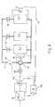
- Fig. 2shows a schematic representation Heating system with a heat pump and an arrangement according to the invention Determination of a setpoint system curve.
- FIG. 1a pump head / flow diagram and a power consumption / flow diagram for a centrifugal pump are shown.
- a characteristic curve of the electrical power consumption of an electric motor driving the centrifugal pumpas a function of the flow rate of the centrifugal pump
- a characteristic curve of the pump headas a function of the flow rate of the centrifugal pump
- the pump parameter paircomprises embodiments of the delivery head and the flow rate and in the other case the electrical power consumed by the Pump drive motor and the flow rate.
- the parameter pair determined in this wayis as Point P1 entered in the performance diagram.
- the speed of the Pump and the delivery head(by means of a differential pressure measurement) measured and off the associated pump characteristic curve determines the delivery rate, which results in a point H1 results.
- a functionis now calculated in a computer-supported manner in the controller using known mathematical curve formation methods (compensation curve formation, etc.) and this mathematical function as a setpoint system curve P plant (Q) or H system (Q) stored in the controller, where it is now available for controlling the pump speed depending on the current delivery rate.
- FIG. 2schematically shows an example of a practical embodiment of the invention shown. It is a heating system with a centrifugal pump 6 and an arrangement according to the invention for controlling the speed of this Centrifugal pump. Liquid heating medium is converted to radiators 4-1 via a line system 2, 4-2 ... 4-n pumped and returned to the pump, whereby the radiators 4-1, 4-2 ... 4-n are each individually controllable by throttle valves 8, so that depending on the position of these throttle valves the flow in the heating circuit and thus the flow rate the centrifugal pump 6 can change.
- the pump 6is driven by a three-phase motor 10, the speed of which is controllable.
- the speedis controlled by a frequency converter 12.
- a power measuring device 14is arranged which measures the electrical power consumption of the motor 10 and a signal representing the power consumption, such as an electrical signal DC voltage supplies.
- a frequency converter with integrated electrical power consumption measurement and corresponding signal outputmay also be suitable for this.
- the power signal output of the power meter 14is connected to the input of a controller 16.
- the output of the controller 16which supplies an output variable determining the desired speed, for example an electrical direct voltage between 0 and 10 V or a direct current between 4 and 20 mA, is connected to the control input of the frequency converter 12 in the manner described above.
- the control characteristic of the controller 16is the function P System (Q) explained above and is defined in the controller as a mathematical function. Controller 16 is preferably a digital controller using a microprocessor.
- a pressure difference sensor 24connected At the inlet and outlet of the most distant from the pump 6 radiator 4-n temporarily to determine the setpoint system curve, a pressure difference sensor 24 connected. If the differential pressure exceeds a predetermined value, one becomes Confirmation sent to controller 16; this is through the transmission line 22 symbolizes, it should be noted that the type of this transmission line in none Way is restricted. It can be a wire or radio line Act transmission of analog or digital signals. If the procedure for Determination of the setpoint system curve is not carried out automatically, it is conceivable that an operator posted on the controller 16 by a second, on Pressure difference sensor 24 posted operator receives instructions and according these instructions, the confirmation signal manually enters the controller 16.
Landscapes
- Engineering & Computer Science (AREA)
- Physics & Mathematics (AREA)
- General Physics & Mathematics (AREA)
- Automation & Control Theory (AREA)
- Mechanical Engineering (AREA)
- General Engineering & Computer Science (AREA)
- Control Of Non-Positive-Displacement Pumps (AREA)
- Electrical Control Of Air Or Fuel Supplied To Internal-Combustion Engine (AREA)
- Control Of Positive-Displacement Pumps (AREA)
Abstract
Description
Translated fromGermanDie Erfindung betrifft ein Verfahren zur Ermittlung einer Sollwert-Anlagenkurve zurRegelung der Förderleistung einer von einem drehzahlgeregelten Elektromotorangetriebenen Pumpe, mittels derer ein Fluid in einer Anlage durch vorgegebeneLeitungen und Verbraucher bewegt wird, deren Anzahl und lichter Querschnitt variabelsind, bei welchem Regelungsverfahren mittels eines Sensors eine für die momentaneFörderleistung der Pumpe repräsentative physikalische Größe erfaßt und ein dieserphysikalischen Größe proportionales elektrisches Signal einem Regler als Ist-Wertzugeführt wird, durch welchen Regler die Drehzahl des Elektromotors und damit dieFörderleistung der Pumpe anhand der Sollwert-Anlagenkurve geregelt wird.The invention relates to a method for determining a setpoint system curve forRegulation of the delivery rate of a speed-controlled electric motordriven pump, by means of which a fluid in a system by predeterminedLines and consumers are moved, their number and clear cross section variableare in which control method using a sensor one for the currentDelivery rate of the pump records representative physical quantity and one of thesephysical quantity proportional electrical signal to a controller as actual valueis supplied by which controller the speed of the electric motor and thus thePump output is regulated based on the setpoint system curve.
Mit einem Elektromotor angetriebene Pumpen, insbesondere Kreiselpumpen werdenhäufig in Anlagen eingesetzt, in welchen sich die von der Anlage her geforderteLeistung der Pumpe über die Zeit verändert. Dies ist beispielsweise bei Pumpen inHeizungsanlagen der Fall. Hier wird die volle Förderleistung nur dann benötigt, wennalle Verbraucher zugeschaltet sind. Im praktischen Betrieb werden jedoch dieVerbraucher, zum Beispiel einzelne Heizkörper, zu gewissen Zeiten nur reduziertbetrieben oder ganz abgeschaltet, so dass sich zeitlich variabel ganz unterschiedlicheBetriebszustände mit unterschiedlichem Förderleistungsbedarf ergeben. Die maximaleLeistung der Pumpe in einer solchen Anlage muss jedoch stets so bemessen werden,dass alle in der Anlage befindlichen Verbraucher auch dann ausreichend versorgtwerden können, wenn sie gleichzeitig mit maximalem Bedarf eingeschaltet sind. Wirddie Pumpe permanent, das heißt auch bei reduziertem Förderleistungsbedarf, mit dervollen Leistung betrieben, so wird - unnötigerweise - die Förderleistung der Maschineüber das erforderliche Maß hinaus angehoben wird. Dieses Verhalten ist anhand einerFlüssigkeitskreiselpumpe im oberen Teil des Diagramms von Fig. 1 zu sehen, das eineSchar von Pumpenkennlinien der Kreiselpumpe darstellt, das heißt, die Förderhöhe Hals Funktion der Fördermenge Q bei einer bestimmten Drehzahl n. In diesem Diagrammist nur die Pumpenkennlinie für eine Drehzahl der Pumpe von n = 50 Hz vollständigdargestellt, weitere Pumpenkennlinien für n = 40,5 Hz, n = 32,4 Hz, n = 26,3 Hz undn = 23,2 Hz sind nur als Kurvenstücke gezeigt.Pumps driven by an electric motor, in particular centrifugal pumpsOften used in systems in which the required by the systemPump performance changed over time. This is the case with pumps inHeating systems the case. The full delivery rate is only required here ifall consumers are switched on. In practical operation, howeverConsumers, for example individual radiators, are only reduced at certain timesoperated or completely switched off, so that there are different timesOperating conditions with different delivery rates result. The maximalHowever, the performance of the pump in such a system must always be measuredthat all consumers in the system are adequately suppliedcan be switched on if they are switched on at the same time with maximum demand. Becomesthe pump permanently, i.e. even with a reduced delivery capacity requirement, with theoperated at full capacity, the conveying capacity of the machine is - unnecessarilyis raised beyond what is necessary. This behavior is based on aLiquid centrifugal pump can be seen in the upper part of the diagram of Fig. 1, the oneRepresentation of the pump characteristics of the centrifugal pump, that is, the delivery head Has a function of the delivery rate Q at a certain speed n. In this diagramonly the pump characteristic is complete for a pump speed of n = 50 Hzshown, further pump characteristics for n = 40.5 Hz, n = 32.4 Hz, n = 26.3 Hz andn = 23.2 Hz are only shown as curve sections.
Die Dimensionierung der erforderlichen Leistung einer solchen Kreiselpumpe in einerAnlage ergibt sich durch Festlegung eines Betriebspunkts Bmax, der sich als derSchnittpunkt einer geforderten maximalen Fördermenge Qmax (in diesem Beispiel 80m3/h), wenn alle Verbraucher vollständig zugeschaltet sind, und der bei dieserFördermenge Qmax für einen reibungslosen Betrieb der Anlage erforderlichenFörderhöhe H (in diesem Beispiel 13 m) darstellt. Die diesen Betriebspunkt Bmaxschneidende Pumpenkennlinie (in diesem Beispiel jene für n = 50 Hz) gibt diemaximale Drehzahl der Pumpe an, die notwendig ist, um bei einem Verbrauch von100% (=Qmax) die erforderliche Förderhöhe aufrecht zu erhalten. Sinkt jedoch dertatsächliche Verbrauch in der Anlage, so erhöht sich bei einem Betrieb der Pumpe mitgleichbleibender Drehzahl n = 50 Hz die Förderhöhe H, d.h. der momentaneBetriebspunkt wandert entlang der Pumpenkennlinie nach links oben. Man erkennt also,dass eine solcherart betriebene Anlage äußerst unwirtschaftlich läuft. Zudem könnenstörende Strömungsgeräusche entstehen, wenn die Leistung wesentlich über der in derAnlage tatsächlich benötigten liegt.The dimensioning of the required output of such a centrifugal pump in a system results from the determination of an operating point Bmax, which is the intersection of a required maximum delivery quantity Qmax (in this example 80 m3 / h) when all consumers are fully switched on and at this delivery rate Qmax represents the delivery head H (13 m in this example) required for smooth operation of the system. The pump characteristic curve that intersects this operating point Bmax (in this example, that for n = 50 Hz) indicates the maximum speed of the pump that is necessary to maintain the required delivery head with a consumption of 100% (= Qmax). However, if the actual consumption in the system drops, the pump head H increases when the pump is operated at a constant speed n = 50 Hz, ie the current operating point moves along the pump characteristic to the top left. It can be seen that a system operated in this way is extremely uneconomical. In addition, disturbing flow noises can occur if the performance is significantly higher than that actually required in the system.
Zur Verbesserung des Energieverbrauchs und des Geräuschpegels einer Pumpe ist esbekannt, die Förderleistung (= Förderhöhe x Fördermenge) einer Kreiselpumpe so zuregeln, dass sich unabhängig von der jeweiligen Fördermenge am Pumpenausgang einekonstante Förderhöhe einstellt, die mittels eines Drucksensors gemessen und einemRegler als Ist-Signal zugeführt werden kann.It is to improve the energy consumption and noise level of a pumpknown, the delivery rate (= delivery head x delivery rate) of a centrifugal pumpregulate that regardless of the respective flow rate at the pump outletconstant head, which is measured by means of a pressure sensor and aController can be supplied as an actual signal.
Eine solche Regelung auf konstante Förderhöhe berücksichtigt jedoch nicht dietatsächlichen Verhältnisse in der Anlage. Insbesondere werden dabei nicht dieunvermeidlichen Druckabfälle im Leitungssystem und den zugeschalteten Verbrauchernberücksichtigt.Such a regulation on a constant delivery rate does not take into account theactual conditions in the plant. In particular, theunavoidable pressure drops in the pipe system and the connected consumersconsidered.
Um die Regelung der Pumpe einer solchen Anlage zu verbessern, ist es dahernotwendig, eine Sollwert-Anlagenkurve zu definieren, die die Anlagenverluste inAbhängigkeit von der Fördermenge zumindest ansatzweise berücksichtigt.It is therefore to improve the control of the pump of such a systemnecessary to define a setpoint system curve that shows the system losses inDependence on the delivery rate at least partially taken into account.
Das Regelungsverhalten einer solchen Anlage mit variabler Sollwert-Anlagenkurve ist inden Diagrammen von Fig. 1 dargestellt, einmal im Förderhöhen/Fördermengen-Diagrammals Sollwert-Anlagenkurve HAnlage(Q), und ein weiteres Mal imLeistungsaufnahme/Fördermengen-Diagramm als Sollwert-Anlagenkurve PAnlage(Q).Beide Sollwert-Anlagenkurven weisen etwa parabolischen Verlauf, allerdings mitunterschiedlichen Steigungen auf.The control behavior of such a system with a variable setpoint system curve is shown in the diagrams of FIG. 1, once in the delivery head / flow rate diagram as the setpoint system curve Hsystem (Q), and again in the power consumption / flow rate diagram as the setpointPlant curve Pplant (Q). Both setpoint system curves are roughly parabolic, but with different gradients.
Im Leistungsaufnahme/Fördermengen-Diagramm ist auch die jeweiligeEnergieeinsparung bei einer Pumpenregelung unter Verwendung der genanntenSollwert-Anlagenkennlinie gegenüber dem Betrieb der Pumpe mit einer konstantenDrehzahl von n = 50 Hz dargestellt.The respective is also in the power consumption / delivery rate diagramEnergy saving in a pump control using the aboveSetpoint system characteristic curve compared to the operation of the pump with a constantSpeed of n = 50 Hz shown.
In der Praxis stellt sich jedoch das Problem, wie man zu einer angemessenen Sollwert-Anlagenkennliniegelangt. Es ist bekannt, solche Sollwert-Anlagenkurven tabellarischanhand von Leitungs- und Verbraucherkenndaten zu ermitteln oder Verlustkurven alsmathematische Funktion zu definieren. Beiden Verfahren ist gemeinsam, dass es sichdabei um theoretische Ansätze handelt, die nicht die tatsächlichen Verhältnisse in derAnlage, z.B. Leitungsquerschnittsverringerung durch Verstopfen oder Verkalken, Leckender Anlage, Wirbelbildung durch Knicke oder starke Biegungen in den Leitungenberücksichtigen können. Daher bieten viele Pumpensysteme auch die Möglichkeit, eineBetriebsperson von Hand Sollwert-Tabellen in einen Regler eingeben zu lassen, die sieaufgrund ihrer Erfahrung oder vorausgegangener Messungen an der Anlage festlegt(siehe z.B. DE-OS 37 04 756). Es ist jedoch leicht einzusehen, dass alle genanntenVerfahren die Anlagenverhältnisse nur unzureichend berücksichtigen.In practice, however, the problem arises of how to get an adequate setpoint system characteristicarrives. It is known to tabulate such setpoint system curvesto be determined on the basis of line and consumer characteristics or loss curves asdefine mathematical function. Both methods have in common that it isThese are theoretical approaches that do not reflect the actual situation in thePlant, e.g. Reduction in the cross-section of the line due to clogging or calcification, leakagesystem, vortex formation due to kinks or strong bends in the linesmay take into account. Therefore, many pump systems also offer the option of oneLet the operator manually enter setpoint tables into a controller that theybased on their experience or previous measurements on the system(see e.g. DE-OS 37 04 756). However, it is easy to see that all of the aboveThe process does not take sufficient account of the plant conditions.
Aus der EP 0 444 269 ist es bekannt, zur Regelung der Leistung einer von einemdrehzahlgeregelten Elektromotor angetriebenen Pumpe in einem geschlossenen System,das Leitungen und Verbraucher umfasst, zunächst in einem Kalibriervorgang beibeliebigem Zustand des Systems das elektrische Signal einer Fluid-Strömungsgeschwindigkeits-Sondein mehreren Punkten mit gezielter Einstellung derPumpenleistung und zugehöriger prozentualer Strömungsgeschwindigkeit des Fluidsvom Stillstand der Pumpe bis zu 100 % Leistung derselben entsprechend 100 %Strömungsgeschwindigkeit zumindest in Stufen aufzunehmen und einem Rechnerjeweils als Meßwert einzugeben, der eine Kennlinie erzeugt, die durch alle von derSonde gelieferten Meßwerte verläuft, wobei die Regelung der Leistung der Pumpe durchden Rechner zunächst entsprechend dieser Kennlinie solange in den durch denKalibriervorgang gegebenen Grenzen erfolgt, bis durch Änderungen im System einehöhere Strömungsgeschwindigkeit des Fluids als bei 100 % Leistung der Pumpe beimKalibriervorgang auftritt, woraufhin vom Rechner der höchste Wert derStrömungsgeschwindigkeit auf der verlängerten Kennlinie als neuer Meßwert für 100 %Leistung der Pumpe festgelegt wird und der Rechner alle prozentualen Werte derStrömungsgeschwindigkeit auf der Kennlinie jeweils in einem Verhältnis verschiebt, dasdem Verhältnis der neuen höchsten Strömungsgeschwindigkeit zu der vorangegangenenentspricht, wobei analoge Adaptionen der Kennlinie jeweils dann durch den Rechnerdurchgeführt werden, wenn eine weitere Erhöhung der Strömungsgeschwindigkeiteintritt.It is known from EP 0 444 269 to regulate the power of one of themspeed controlled electric motor driven pump in a closed system,which includes lines and consumers, first in a calibration processany state of the system the electrical signal of a fluid flow rate probein several points with targeted adjustment of thePump output and associated percentage flow rate of the fluidfrom the standstill of the pump to 100% performance of the pump corresponding to 100%Record flow rate at least in stages and a computerEnter each as a measured value that generates a characteristic curve that runs through all of theMeasured values supplied by the probe, the regulation of the performance of the pump being carried outthe computer initially according to this characteristic curve in the by theCalibration process given limits until changes in the systemhigher flow velocity of the fluid than with 100% performance of the pump atCalibration process occurs, whereupon the highest value of the computerFlow velocity on the extended characteristic curve as a new measured value for 100%Power of the pump is set and the calculator all percentages of theFlow speed on the characteristic curve shifts in a ratio thatthe ratio of the new highest flow rate to the previous onecorresponds, with analog adaptations of the characteristic curve then by the computerbe performed if there is a further increase in flow rateentry.
Die vorliegende Erfindung bietet ein Verfahren zur Ermittlung einer Sollwert-Anlagenkurvean, das die geschilderten Nachteile des Standes der Technik vermeidetund den tatsächlichen Anlagenverhältnissen gerecht wird.The present invention provides a method for determining a setpoint system curvewhich avoids the disadvantages of the prior art describedand does justice to the actual plant conditions.
Das erfindungsgemäße Verfahren weist die folgenden Schritte auf:
Die dabei errechnete Kurve muss nicht notwendigerweise durch alle ermitteltenParameterpaare hindurchgehen, sondern kann für einen optimierten Kurvenverlauf auchdazwischen verlaufen.The curve calculated here does not necessarily have to be determined by allPass parameter pairs, but can also for an optimized curverun in between.
Vorzugsweise wird der Verbraucher-Betriebsparameters an dem von der Pumpe amentferntesten angeordneten Verbraucher erfasst, da davon ausgegangen werden kann,dass der Wert dieses Parameters am letzten Verbraucher aufgrund der Leitungsverlusteminimal ist, so dass bei korrekter Einstellung für den entferntesten Verbraucher auch alleanderen Verbraucher im System ausreichend versorgt werden. Kennt man jedochaufgrund empirischer Versuche oder Berechnungen den Zusammenhang der Werte des Verbraucher-Betriebsparameters am entferntesten Verbraucher und der Werte an einemanderen Verbraucher, so kann auch dieser andere Verbraucher zur Durchführung desVerfahrens herangezogen werden, wobei der genannte Zusammenhang entsprechendzu berücksichtigen ist.Preferably, the consumer operating parameter on the pumpremotely located consumers, since it can be assumedthat the value of this parameter at the last consumer due to the line lossesis minimal, so that with the correct setting, even the most distant consumerother consumers in the system are adequately supplied. But you knowbased on empirical experiments or calculations the relationship of the values of theConsumer operating parameters are the most distant consumer and the values at oneother consumer, this other consumer can also carry out theProcedures are used, the relationship mentioned accordinglyis to be considered.
Das Übermitteln eines Bestätigungs-Signals an den Regler, sobald der Verbraucher-Betriebsparameterden vorgegebenen Wert erreicht hat, kann vorzugsweiseautomatisiert ablaufen, beispielsweise über eine Daten-Fernübertragung. In einereinfachen Variante kann die Übermittlung des Bestätigungssignal aber auch manuell,beispielsweise durch Kontakt zwischen zwei Bedienpersonen, davon eine mit Zugangzum Regler und die andere am entfernten Verbraucher postiert, erfolgen.The transmission of a confirmation signal to the controller as soon as the consumer operating parameterhas reached the predetermined value, can preferablyrun automatically, for example via remote data transmission. In asimple variant, the transmission of the confirmation signal can also be done manually,for example, through contact between two operators, one of whom has accessto the controller and the other at the remote consumer.
Um eine möglichst genaue Sollwert-Anlagenkurve zu erhalten, ist es zweckmäßig, wennder Verfahrensschritt e) vielfach, zumindest aber zweimal hintereinander durchlaufenwird.In order to obtain a setpoint system curve that is as accurate as possible, it is advisable ifProcess step e) is carried out many times, but at least twice in successionbecomes.
Bevorzugt ist der Verbraucher-Betriebsparameter ein Differenzdruck zwischen demEingang und dem Ausgang des entfernten Verbrauchers, da ein solcher Differenzdruckauf einfache Weise durch vorübergehendes Anschließen eines Differenzdruck-Sensorsam Zu- und Ablauf des Verbrauchers ermittelbar ist.The consumer operating parameter is preferably a differential pressure between theInlet and outlet of the remote consumer because of such a differential pressuresimply by temporarily connecting a differential pressure sensorcan be determined at the inlet and outlet of the consumer.
Bevorzugt umfasst das Pumpen-Parameterpaar die Pumpen-Fördermenge und dieaufgenommene elektrische Leistung des Pumpen-Antriebsmotors und wird ermitteltdurch Messen von zwei Parametern aus der Pumpen-Fördermenge, der aufgenommenenelektrischen Leistung des Pumpen-Antriebsmotors und der Drehzahl der Pumpe,gegebenenfalls unter Errechnen des fehlenden Parameters aus den mathematischenZusammenhängen zwischen diesen drei Parametern. Es läßt sich nämlich eineKurvenschar angeben, die für jede Drehzahl der Pumpe einen charakteristischen Verlaufder aufgenommenen elektrischen Leistung des Pumpenantriebsmotors in Abhängigkeitvon der Fördermenge darstellt. Da sich die Messung der Drehzahl und der Leistungsaufnahme in ein Pumpen-Regelgerät oder einen Frequenzumrichter integrierenläßt, kann somit eine äußerst betriebssichere und kostengünstige Konstruktion einesPumpenregelgeräts erreicht werden.The pair of pump parameters preferably includes the pump delivery rate and theconsumed electrical power of the pump drive motor and is determinedby measuring two parameters from the pump delivery rate, the recorded rateelectrical power of the pump drive motor and the speed of the pump,if necessary, calculating the missing parameter from the mathematicalRelationships between these three parameters. There can be oneSpecify the family of curves that is characteristic for each speed of the pumpthe electrical power consumed by the pump drive motor in dependencerepresents the flow rate. Since the measurement of the speed and theIntegrate power consumption into a pump control unit or a frequency convertercan be an extremely reliable and inexpensive construction of aPump control device can be achieved.
Eine alternative bevorzugte Ausführungsform des erfindungsgemäßen Verfahrens istdadurch gekennzeichnet, dass das Pumpen-Parameterpaar die Pumpen-Fördermengeund die Pumpen-Förderhöhe umfasst und ermittelt wird durch Messen von zweiParametern aus der Pumpen-Fördermenge, der Pumpen-Förderhöhe und der Drehzahlder Pumpe, gegebenenfalls unter Errechnen des fehlenden Parameters aus denmathematischen Zusammenhängen zwischen diesen drei Parametern. Es läßt sichnämlich auch eine Kurvenschar angeben, die für jede Drehzahl der Pumpe einencharakteristischen Verlauf der Pumpen-Förderhöhe in Abhängigkeit von derFördermenge darstellt. Da sich die Messung der Drehzahl in ein Pumpen-Regelgerätoder einen Frequenzumrichter integrieren läßt, und die Pumpen-Förderhöhe über einenDruckdifferenz-Sensor zwischen Pumpenaus- und eingang ermittelt werden kann, ist mitdieser Ausführung eine äußerst betriebssichere Konstruktion eines Pumpenregelgerätsmöglich.An alternative preferred embodiment of the method according to the invention ischaracterized in that the pump parameter pair is the pump delivery rateand the pump head includes and is determined by measuring twoParameters from the pump delivery rate, the pump delivery head and the speedthe pump, if necessary by calculating the missing parameter from themathematical relationships between these three parameters. It can benamely also specify a family of curves, one for each speed of the pumpcharacteristic course of the pump head depending on theRepresents output. Since the measurement of the speed in a pump control unitor integrates a frequency converter, and the pump head via onePressure difference sensor between pump outlet and inlet can be determined withthis version is an extremely reliable design of a pump control unitpossible.
Zur näheren Erläuterung der Erfindung werden im Folgenden unter Bezugnahme auf diebeiliegenden Zeichnungen Ausführungsformen davon beschrieben. In den Zeichnungenzeigt Fig. 1 Diagramme einer Pumpenkennlinienschar, d.h. Förderhöhe in Abhängigkeitvon der Fördermenge und der Drehzahl der Pumpe, und eine Schar vonLeistungsaufnahmekennlinien des Pumpenmotors in Abhängigkeit von der Pumpen-Fördermengeund der Drehzahl. Fig. 2 zeigt in schematischer Darstellung eineHeizungsanlage mit einer Heizpumpe und einer erfindungsgemäßen Anordnung zurErmittlung einer Sollwert-Anlagenkurve.For a more detailed explanation of the invention are described below with reference to theaccompanying drawings described embodiments thereof. In the drawings1 shows diagrams of a family of pump characteristics, i.e. Head dependentof the delivery rate and speed of the pump, and a bevy ofPower consumption characteristics of the pump motor depending on the pump delivery rateand the speed. Fig. 2 shows a schematic representationHeating system with a heat pump and an arrangement according to the inventionDetermination of a setpoint system curve.
Zunächst auf Fig. 1 Bezug nehmend ist darin ein Pumpen-Förderhöhen/Fördermengen-Diagrammund ein Leistungsaufnahme/Fördermengen-Diagramm für eine Kreiselpumpedargestellt. Wie bereits erwähnt, existiert für jede Drehzahl der Kreiselpumpe eine charakteristische Kurve der elektrischen Leistungsaufnahme eines die Kreiselpumpeantreibenden Elektromotors in Abhängigkeit von der Fördermenge der Kreiselpumpe,und eine charakteristische Kurve der Pumpen-Förderhöhe in Abhängigkeit von derFördermenge der Kreiselpumpe, so dass die beiden Diagramme tatsächlich ausKurvenscharen diskreter Kurven für die verschiedenen Pumpendrehzahlen bestehen. InFig. 1 sind die Leistungsaufnahmekurve ("Leistungskennlinie") und dieFörderhöhenkurve ("Pumpenkennlinie") über der Fördermenge für einePumpendrehzahl von n = 50 Hz vollständig dargestellt; andere Leistungskennlinienund Pumpenkennlinien für Drehzahlen von n = 23,2 Hz, n = 26,3 Hz, n = 32,4 Hz, n= 40,5 Hz sind nur stückweise in interessierenden Abschnitten dargestellt. Weiters istin diesen Diagrammen bereits die gesuchte Sollwert-Anlagenkurve als FunktionPAnlage(Q) der Motor-Leistungsaufnahme in Abhängigkeit von der Pumpen-Fördermengebzw. als Funktion HAnlage(Q) der Pumpen-Förderhöhe in Abhängigkeit von der Pumpen-Fördermengeeingetragen, die jeweils von Parametern der gesamten Anlage bestimmtwerden.Referring first to FIG. 1, a pump head / flow diagram and a power consumption / flow diagram for a centrifugal pump are shown. As already mentioned, for each speed of the centrifugal pump there is a characteristic curve of the electrical power consumption of an electric motor driving the centrifugal pump as a function of the flow rate of the centrifugal pump, and a characteristic curve of the pump head as a function of the flow rate of the centrifugal pump, so that the two diagrams actually consist of sets of curves of discrete curves for the different pump speeds. In Fig. 1, the power consumption curve ("power characteristic") and the head curve ("pump characteristic") against the flow rate for a pump speed of n = 50 Hz are shown completely; other performance curves and pump curves for speeds of n = 23.2 Hz, n = 26.3 Hz, n = 32.4 Hz, n = 40.5 Hz are only shown in sections in sections of interest. Furthermore, the desired setpoint system curve is already entered in these diagrams as function Psystem (Q) of the motor power consumption depending on the pump delivery rate or as function Hsystem (Q) of the pump delivery head depending on the pump delivery rate , which are determined by parameters of the entire system.
Im folgenden wird erläutert, wie man mittels des erfindungsgemäßen Verfahrens zu dengesuchten Sollwert-Anlagenkurven PAnlage(Q) bzw. HAnlage(Q) gelangt.The following explains how the desired setpoint system curves Psystem (Q) and Hsystem (Q) are obtained by means of the method according to the invention.
Zunächst werden alle Verbraucher in der Anlage geschlossen und ein DifferenzdruckSensoran den von der Pumpe am entferntesten angeordneten Verbraucherangeschlossen. Dieser Differenzdruck muss einen vorbestimmten Wert erreichen oderübersteigen, damit seine Funktion im normalen Betrieb gewährleistet werden kann, z.B.um bei einem Heizkörper als Verbraucher sicherzustellen, dass Heizmedium inausreichender Menge und Geschwindigkeit durch ihn hindurchströmt. Daraufhin wirddie momentane Pumpenleistung variiert, bis der Differenzdruck am genanntenVerbraucher den vorgegebenen Wert annimmt. Das Erreichen dieses Werts wirdmanuell oder automatisch an einen Regler signalisiert. Auf den Erhalt des Bestätigungs-Signalswird der Regler veranlasst, die momentanen Werte eines Pumpen-Parameterpaarszu ermitteln, das für die momentane Förderleistung der Pumpe repräsentativ ist und diese Werte abzuspeichern. In den dargestelltenAusführungsformen umfasst das Pumpen-Parameterpaar in einem Fall die Förderhöheund die Fördermenge und im anderen Fall die aufgenommene elektrische Leistung desPumpen-Antriebsmotors und die Fördermenge. Bevorzugt erfolgt die Ermittlung dieserWerte-Paare im ersten Fall durch eine Messung der Pumpendrehzahl und deraufgenommenen elektrischen Leistung, woraus sich aus der zugehörigenLeistungskennlinie, die im Regler beispielsweise in einem Kennfeld gespeichert seinkann, die Pumpen-Fördermenge errechnen läßt. Das so ermittelte Parameterpaar ist alsPunkt P1 im Leistungsdiagramm eingetragen. Im zweiten Fall werden die Drehzahl derPumpe und die Förderhöhe (mittels einer Differenzdruck-Messung) gemessen und ausder zugehörigen Pumpenkennlinie die Fördermenge ermittelt, wodurch sich ein PunktH1 ergibt.First of all, all consumers in the system are closed and a differential pressure sensorto the consumer most distant from the pumpconnected. This differential pressure must reach a predetermined value orexceed so that its function can be guaranteed in normal operation, e.g.to ensure that the heating medium insufficient quantity and speed flows through it. Thereupon willthe current pump output varies until the differential pressure at the mentionedConsumer assumes the specified value. Reaching this value willsignaled manually or automatically to a controller. On receipt of the confirmation signalthe controller is triggered, the current values of a pump parameter pairto determine that for the current flow rate of the pumpis representative and save these values. In the illustratedIn one case, the pump parameter pair comprises embodiments of the delivery headand the flow rate and in the other case the electrical power consumed by thePump drive motor and the flow rate. This is preferably determinedValue pairs in the first case by measuring the pump speed and theconsumed electrical power, resulting from the associatedPerformance characteristic curve that is stored in the controller, for example, in a mapcan, the pump delivery rate can be calculated. The parameter pair determined in this way is asPoint P1 entered in the performance diagram. In the second case, the speed of thePump and the delivery head (by means of a differential pressure measurement) measured and offthe associated pump characteristic curve determines the delivery rate, which results in a pointH1 results.
Nach Abschluss dieser ersten Messung werden ein oder mehrere Verbraucher geöffnetund das geschilderte Messverfahren wiederholt. Diese Prozedur wird für eine jeweilsgeänderte Anzahl an offenen Verbrauchern noch mehrmals wiederholt, so dass sich imersten Fall eine Messwert-Reihe an Punkten P1 bis P4 und im zweiten Fall eine Reihe anPunkten H1 bis H4 ergibt.After completing this first measurement, one or more consumers are openedand repeated the measurement procedure described. This procedure is for one at a timechanged number of open consumers repeated several times, so that in thein the first case a series of measured values at points P1 to P4 and in the second case a seriesPoints H1 to H4 results.
Aus den abgespeicherten Werten der Pumpen-Parameterpaare (Punkte P1 - P4 bzw. H1- H4) wird nunmehr im Regler computergestützt unter Verwendung bekanntermathematischer Kurvenbildungsverfahren (Ausgleichskurvenbildung etc.) eine Funktionerrechnet und diese mathematische Funktion als Sollwert-Anlagenkurve PAnlage(Q) bzw.HAnlage(Q) im Regler abgespeichert, wo sie nunmehr zur Regelung der Pumpendrehzahlin Abhängigkeit von der momentanen Fördermenge zur Verfügung steht.From the stored values of the pump parameter pairs (points P1 - P4 or H1 - H4), a function is now calculated in a computer-supported manner in the controller using known mathematical curve formation methods (compensation curve formation, etc.) and this mathematical function as a setpoint system curve Pplant (Q) or Hsystem (Q) stored in the controller, where it is now available for controlling the pump speed depending on the current delivery rate.
In Fig. 2 ist schematisch ein Beispiel für eine praktische Ausführungsform der Erfindungdargestellt. Es handelt sich dabei um eine Heizungsanlage mit einer Kreiselpumpe 6und einer erfindungsgemäßen Anordnung zur Regelung der Drehzahl dieserKreiselpumpe. Über ein Leitungssystem 2 wird flüssiges Heizmedium zu Heizkörpern 4-1, 4-2 ... 4-n gepumpt und zur Pumpe zurückgeführt, wobei die Heizkörper 4-1, 4-2 ...4-n jeweils einzeln durch Drosselventile 8 steuerbar sind, so dass sich je nach Stellungdieser Drosselventile der Durchfluss im Heizungskreislauf und damit die Fördermengeder Kreiselpumpe 6 verändern kann.2 schematically shows an example of a practical embodiment of the inventionshown. It is a heating system with a centrifugal pump 6and an arrangement according to the invention for controlling the speed of thisCentrifugal pump. Liquid heating medium is converted to radiators 4-1 via a
Die Pumpe 6 wird durch einen Drehstrom-Motor 10 angetrieben, dessen Drehzahlsteuerbar ist. Die Steuerung der Drehzahl erfolgt in diesem Beispiel durch einenFrequenzumrichter 12. In der elektrischen Verbindungsleitung zwischenFrequenzumrichter 12 und Drehstrom-Motor 10 ist ein Leistungsmessgerät 14angeordnet, das die elektrische Leistungsaufnahme des Motors 10 misst und ein dieLeistungsaufnahme repräsentierendes Signal, wie z.B. eine elektrische Gleichspannung,liefert. Hierzu eignet sich gegebenenfalls auch ein Frequenzumrichter mit integrierterelektrischer Leistungsaufnahme-Messung und entsprechendem Signalausgang. Fernerwäre es ebenfalls möglich, die elektrische Leistungsaufnahme vor demFrequenzumrichter zu messen, da sich der Leistungsverbrauch des Frequenzumrichtersim Vergleich zu jenem des Motors kaum auf die Regelung auswirkt. Der Leistungs-Signalausgangdes Leistungsmessgeräts 14 ist mit dem Eingang eines Reglers 16verbunden. Der Ausgang des Reglers 16, der in der oben beschriebenen Weise eine diegewünschte Drehzahl bestimmende Ausgangsgröße, z.B. eine elektrischeGleichspannung zwischen 0 und 10 V oder einen Gleichstrom zwischen 4 und 20 mAliefert, ist an den Steuerungseingang des Frequenzumrichters 12 angeschlossen. DieRegelungskennlinie des Reglers 16 ist die oben erläuterte Funktion PAnlage(Q) und ist imRegler als mathematische Funktion definiert. Der Regler 16 ist vorzugsweise eindigitales Regelgerät unter Verwendung eines Mikroprozessors.The pump 6 is driven by a three-
Am Zu- und Ablauf des am weitesten von der Pumpe 6 entfernten Heizkörpers 4-n wirdzur Ermittlung der Sollwert-Anlagenkurve vorübergehend ein Druckdifferenz-Sensor 24angeschlossen. Übersteigt der Differenzdruck einen vorgegebenen Wert, so wird eineBestätigung zum Regler 16 übermittelt; dies ist durch die Übertragungseitung 22symbolisiert, wobei zu beachten ist, dass die Art dieser Übertragungsleitung in keiner Weise eingeschränkt ist. Es kann sich dabei um eine Draht- oder Funkleitung zurÜbertragung analoger oder digitaler Signale handeln. Wenn das Verfahren zurErmittlung der Sollwert-Anlagenkurve nicht automatisiert durchgeführt wird, ist es auchdenkbar, dass eine am Regler 16 postierte Bedienperson von einer zweiten, amDruckdifferenz-Sensor 24 postierten Bedienperson Anweisungen erhält und gemäßdiesen Anweisungen das Bestätigungs-Signal händisch in den Regler 16 eingibt.At the inlet and outlet of the most distant from the pump 6 radiator 4-ntemporarily to determine the setpoint system curve, a
Um zu demonstrieren, dass neben einer Regelung der Pumpendrehzahl durch Messungder aufgenommenen elektrischen Leistung des Pumpenmotors als Rückkopplungsgrößeauch andere Regelungsverfahren, wie z.B. eines mit Differenzdruckmessung alsRückkopplungsgröße infrage kommen, ist in Fig. 2 strichliert ein Druckdifferenz-Sensor18 zwischen Pumpenausgang und -eingang angeschlossen. Um weiters zu zeigen, dassauch die Pumpen-Fördermenge direkt gemessen werden kann, ist strichliert einentsprechendes Fördermengen-Messgerät 20 eingezeichnet.To demonstrate that in addition to regulating the pump speed by measurementthe electrical power consumed by the pump motor as a feedback variableother control procedures, such as one with differential pressure measurement asFeedback size come into question, is a dashed line in Fig. 2, a
Claims (5)
Translated fromGermanPriority Applications (7)
| Application Number | Priority Date | Filing Date | Title |
|---|---|---|---|
| AT01890242TATE273533T1 (en) | 2001-08-22 | 2001-08-22 | METHOD FOR DETERMINING A PUMP CONTROL CHARACTERISTICS |
| DK01890242TDK1286240T3 (en) | 2001-08-22 | 2001-08-22 | Method for determining a pump control characteristic |
| ES01890242TES2227112T3 (en) | 2001-08-22 | 2001-08-22 | PROCEDURE TO DETERMINE A CHARACTERISTICS OF A PUMP. |
| DE50103236TDE50103236D1 (en) | 2001-08-22 | 2001-08-22 | Method for determining a pump control characteristic |
| EP01890242AEP1286240B1 (en) | 2001-08-22 | 2001-08-22 | Method of determining a pump-characteristic |
| CA002396634ACA2396634A1 (en) | 2001-08-22 | 2002-07-31 | Process for determining a reference characteristic for controlling a pump |
| US10/211,208US6758655B2 (en) | 2001-08-22 | 2002-08-02 | Process for determining a reference characteristic for controlling a pump |
Applications Claiming Priority (1)
| Application Number | Priority Date | Filing Date | Title |
|---|---|---|---|
| EP01890242AEP1286240B1 (en) | 2001-08-22 | 2001-08-22 | Method of determining a pump-characteristic |
Publications (2)
| Publication Number | Publication Date |
|---|---|
| EP1286240A1true EP1286240A1 (en) | 2003-02-26 |
| EP1286240B1 EP1286240B1 (en) | 2004-08-11 |
Family
ID=8185148
Family Applications (1)
| Application Number | Title | Priority Date | Filing Date |
|---|---|---|---|
| EP01890242AExpired - LifetimeEP1286240B1 (en) | 2001-08-22 | 2001-08-22 | Method of determining a pump-characteristic |
Country Status (7)
| Country | Link |
|---|---|
| US (1) | US6758655B2 (en) |
| EP (1) | EP1286240B1 (en) |
| AT (1) | ATE273533T1 (en) |
| CA (1) | CA2396634A1 (en) |
| DE (1) | DE50103236D1 (en) |
| DK (1) | DK1286240T3 (en) |
| ES (1) | ES2227112T3 (en) |
Cited By (4)
| Publication number | Priority date | Publication date | Assignee | Title |
|---|---|---|---|---|
| DE102007058211A1 (en)* | 2007-12-04 | 2009-06-10 | Siemens Ag | Method for operating a fluidic line system |
| DE102010055241A1 (en)* | 2010-12-20 | 2012-06-21 | Airbus Operations Gmbh | Fluidic supply system with a plurality of consumers |
| EP3078413A1 (en)* | 2015-03-27 | 2016-10-12 | Uniflex Co., Ltd. | Mixing capacity measuring device |
| US10022685B2 (en) | 2012-12-25 | 2018-07-17 | Uniflex Company, Ltd. | Mixing device for mixing liquids in a mixing tank |
Families Citing this family (28)
| Publication number | Priority date | Publication date | Assignee | Title |
|---|---|---|---|---|
| IL156535A (en)* | 2003-06-19 | 2006-12-10 | Maytronics Ltd | Pool cleaning apparatus |
| US8540493B2 (en) | 2003-12-08 | 2013-09-24 | Sta-Rite Industries, Llc | Pump control system and method |
| US7845913B2 (en)* | 2004-08-26 | 2010-12-07 | Pentair Water Pool And Spa, Inc. | Flow control |
| US8602745B2 (en) | 2004-08-26 | 2013-12-10 | Pentair Water Pool And Spa, Inc. | Anti-entrapment and anti-dead head function |
| US8043070B2 (en) | 2004-08-26 | 2011-10-25 | Pentair Water Pool And Spa, Inc. | Speed control |
| US7874808B2 (en) | 2004-08-26 | 2011-01-25 | Pentair Water Pool And Spa, Inc. | Variable speed pumping system and method |
| US8480373B2 (en) | 2004-08-26 | 2013-07-09 | Pentair Water Pool And Spa, Inc. | Filter loading |
| US7686589B2 (en) | 2004-08-26 | 2010-03-30 | Pentair Water Pool And Spa, Inc. | Pumping system with power optimization |
| US8469675B2 (en) | 2004-08-26 | 2013-06-25 | Pentair Water Pool And Spa, Inc. | Priming protection |
| US8303260B2 (en)* | 2006-03-08 | 2012-11-06 | Itt Manufacturing Enterprises, Inc. | Method and apparatus for pump protection without the use of traditional sensors |
| WO2010042406A1 (en) | 2008-10-06 | 2010-04-15 | Pentair Water Pool And Spa, Inc. | Method of operating a safety vacuum release system |
| TWI411975B (en)* | 2008-11-06 | 2013-10-11 | Ind Tech Res Inst | Method of predicting level of customer amount, and method of controlling temperature of aircondiction by using the same |
| US8311680B2 (en)* | 2008-12-26 | 2012-11-13 | Industrial Technology Research Institute | Method of determining demand threshold, and method and system of demand control |
| US9556874B2 (en) | 2009-06-09 | 2017-01-31 | Pentair Flow Technologies, Llc | Method of controlling a pump and motor |
| CN102195557B (en)* | 2010-03-12 | 2013-01-23 | 时代新纪元科技集团有限公司 | Pump motor control method and device |
| US8700221B2 (en) | 2010-12-30 | 2014-04-15 | Fluid Handling Llc | Method and apparatus for pump control using varying equivalent system characteristic curve, AKA an adaptive control curve |
| US10119545B2 (en)* | 2013-03-01 | 2018-11-06 | Fluid Handling Llc | 3-D sensorless conversion method and apparatus for pump differential pressure and flow |
| US9938970B2 (en)* | 2011-12-16 | 2018-04-10 | Fluid Handling Llc | Best-fit affinity sensorless conversion means or technique for pump differential pressure and flow monitoring |
| CN104024965B (en) | 2011-12-16 | 2018-02-13 | 流体处理有限责任公司 | Dynamic linear control method and apparatus for variable speed pump control |
| US9710610B2 (en) | 2012-07-25 | 2017-07-18 | Covidien Lp | Enteral feeding pump with flow adjustment |
| EP2562424B1 (en) | 2012-09-07 | 2015-05-27 | Gidelmar, S.A. | Method and equipment for controlling a multipoint fluid distribution system |
| US9885360B2 (en) | 2012-10-25 | 2018-02-06 | Pentair Flow Technologies, Llc | Battery backup sump pump systems and methods |
| ES2881386T3 (en) | 2013-09-24 | 2021-11-29 | Kpr Us Llc | Feeding set and enteral feeding pump |
| RU2685367C2 (en)* | 2013-11-27 | 2019-04-17 | Флюид Хэндлинг ЭлЭлСи | 3d sensorless conversion device for pump differential pressure and flow rate |
| US9470217B2 (en)* | 2014-03-27 | 2016-10-18 | Mohsen Taravat | Method and device for measuring and controlling amount of liquid pumped |
| DE102014110911A1 (en)* | 2014-07-31 | 2016-02-04 | Xylem Ip Management S.À.R.L. | Method for operating a liquid delivery system and delivery pump |
| EP3940237B1 (en)* | 2020-07-17 | 2022-08-24 | Grundfos Holding A/S | Multi-pump control system |
| CN114075820A (en)* | 2020-08-14 | 2022-02-22 | 赛莱默欧洲有限公司 | Integrated pump brake control device |
Citations (3)
| Publication number | Priority date | Publication date | Assignee | Title |
|---|---|---|---|---|
| DE3606751A1 (en)* | 1985-03-04 | 1986-09-04 | Joh. Vaillant Gmbh U. Co, 5630 Remscheid | Method for determining a desired value |
| US4976590A (en)* | 1988-06-08 | 1990-12-11 | Baldwin Brian E | Fluid conduit-responsively adjustable pump arrangement and pump/conduit arrangement and method, and fluid conduits therefor |
| US6142752A (en)* | 1997-09-05 | 2000-11-07 | Ntn Corporation | Centrifugal fluid pump assembly |
Family Cites Families (2)
| Publication number | Priority date | Publication date | Assignee | Title |
|---|---|---|---|---|
| DE3724756A1 (en) | 1987-07-25 | 1989-02-09 | Basf Ag | BASICLY SUBSTITUTED BENZOFURANCARBONIC ACID AMIDES, PROCESS FOR THEIR PRODUCTION AND THERAPEUTIC AGENTS CONTAINING THE SAME |
| DE4006186C2 (en) | 1990-02-28 | 1996-09-26 | Ewald Hennel | Method for controlling the speed of a pump driven by a speed-controlled electric motor |
- 2001
- 2001-08-22EPEP01890242Apatent/EP1286240B1/ennot_activeExpired - Lifetime
- 2001-08-22DKDK01890242Tpatent/DK1286240T3/enactive
- 2001-08-22DEDE50103236Tpatent/DE50103236D1/ennot_activeExpired - Lifetime
- 2001-08-22ATAT01890242Tpatent/ATE273533T1/enactive
- 2001-08-22ESES01890242Tpatent/ES2227112T3/ennot_activeExpired - Lifetime
- 2002
- 2002-07-31CACA002396634Apatent/CA2396634A1/ennot_activeAbandoned
- 2002-08-02USUS10/211,208patent/US6758655B2/ennot_activeExpired - Lifetime
Patent Citations (3)
| Publication number | Priority date | Publication date | Assignee | Title |
|---|---|---|---|---|
| DE3606751A1 (en)* | 1985-03-04 | 1986-09-04 | Joh. Vaillant Gmbh U. Co, 5630 Remscheid | Method for determining a desired value |
| US4976590A (en)* | 1988-06-08 | 1990-12-11 | Baldwin Brian E | Fluid conduit-responsively adjustable pump arrangement and pump/conduit arrangement and method, and fluid conduits therefor |
| US6142752A (en)* | 1997-09-05 | 2000-11-07 | Ntn Corporation | Centrifugal fluid pump assembly |
Cited By (6)
| Publication number | Priority date | Publication date | Assignee | Title |
|---|---|---|---|---|
| DE102007058211A1 (en)* | 2007-12-04 | 2009-06-10 | Siemens Ag | Method for operating a fluidic line system |
| US8290633B2 (en) | 2007-12-04 | 2012-10-16 | Siemens Aktiengesellschaft | Method for operating a fluidic pipeline system |
| DE102010055241A1 (en)* | 2010-12-20 | 2012-06-21 | Airbus Operations Gmbh | Fluidic supply system with a plurality of consumers |
| US10386136B2 (en) | 2010-12-20 | 2019-08-20 | Airbus Operations Gmbh | Supply system with a plurality of consumers |
| US10022685B2 (en) | 2012-12-25 | 2018-07-17 | Uniflex Company, Ltd. | Mixing device for mixing liquids in a mixing tank |
| EP3078413A1 (en)* | 2015-03-27 | 2016-10-12 | Uniflex Co., Ltd. | Mixing capacity measuring device |
Also Published As
| Publication number | Publication date |
|---|---|
| US20030039556A1 (en) | 2003-02-27 |
| CA2396634A1 (en) | 2003-02-22 |
| ATE273533T1 (en) | 2004-08-15 |
| DK1286240T3 (en) | 2004-12-13 |
| DE50103236D1 (en) | 2004-09-16 |
| ES2227112T3 (en) | 2005-04-01 |
| US6758655B2 (en) | 2004-07-06 |
| EP1286240B1 (en) | 2004-08-11 |
Similar Documents
| Publication | Publication Date | Title |
|---|---|---|
| EP1286240B1 (en) | Method of determining a pump-characteristic | |
| EP2145112B1 (en) | Device and method for fault monitoring | |
| DE69911306T2 (en) | Method and device for regulating a line network | |
| EP2696175B1 (en) | Method for detecting the flow rate of a centrifugal pump | |
| EP2039939B2 (en) | Method for monitoring an energy conversion device | |
| EP2469094B1 (en) | Method for operating a double pump or multi pump assembly | |
| EP3123033B1 (en) | Method for determining the hydraulic operating point of a pump assembly | |
| EP2708825B1 (en) | Method for controlling a circulating pump in an assembly with at least two circuits | |
| DE19742799B4 (en) | Automatic adjustment of the adjustment range of a pressure control loop in multi-pump systems | |
| AT405996B (en) | METHOD FOR REGULATING THE SPEED OF AN ELECTRIC MOTOR AND DEVICE FOR IMPLEMENTING THE METHOD | |
| DE102014006258A1 (en) | Method for controlling a pump system and regulated pump system | |
| DE10035829C2 (en) | Method for operating a ventilation device and ventilation device | |
| EP2550112B1 (en) | Device for delivering a medium at an adjustable temperature, associated method for temperature control and calibration | |
| DE4006186A1 (en) | Electrically-operated pump regulation system - corrects rotation rate of electric pump motor dependent on measured flow velocity | |
| EP3048305B1 (en) | Reduction of the energy consumption of a variable speed water pump taking into account the current system load | |
| EP4279745B1 (en) | Method for determining the static head of a pump | |
| EP0470935A1 (en) | Method of measuring heat quantities and heating installation applying this method | |
| EP3369934B1 (en) | Circulation pump | |
| EP3267039B1 (en) | System and method for controlling a pump station | |
| DE102007051045B4 (en) | Arrangement with vacuum pump and process | |
| EP3997389B1 (en) | Method for controlling an arrangement consisting of a heating pump and a three-way mixer valve | |
| DE102021209569A1 (en) | Electronic control unit, hydraulic system and method of controlling a hydraulic system | |
| DE102018212876A1 (en) | Control method for machine with converter-driven electric drive | |
| EP3879199B1 (en) | Method for controlling a volume flow flowing in an air duct of an air conditioning and / or room air system and system for controlling a volume flow in an air duct of an air conditioning and / or room air system | |
| WO1999061964A1 (en) | Method for calibrating the speed of an electric pump-drive motor |
Legal Events
| Date | Code | Title | Description |
|---|---|---|---|
| PUAI | Public reference made under article 153(3) epc to a published international application that has entered the european phase | Free format text:ORIGINAL CODE: 0009012 | |
| AK | Designated contracting states | Kind code of ref document:A1 Designated state(s):AT BE CH CY DE DK ES FI FR GB GR IE IT LI LU MC NL PT SE TR | |
| AX | Request for extension of the european patent | Extension state:AL LT LV MK RO SI | |
| 17P | Request for examination filed | Effective date:20030510 | |
| AKX | Designation fees paid | Designated state(s):AT BE CH CY DE DK ES FI FR GB GR IE IT LI LU MC NL PT SE TR | |
| GRAP | Despatch of communication of intention to grant a patent | Free format text:ORIGINAL CODE: EPIDOSNIGR1 | |
| GRAS | Grant fee paid | Free format text:ORIGINAL CODE: EPIDOSNIGR3 | |
| GRAA | (expected) grant | Free format text:ORIGINAL CODE: 0009210 | |
| AK | Designated contracting states | Kind code of ref document:B1 Designated state(s):AT BE CH CY DE DK ES FI FR GB GR IE IT LI LU MC NL PT SE TR | |
| PG25 | Lapsed in a contracting state [announced via postgrant information from national office to epo] | Ref country code:TR Free format text:LAPSE BECAUSE OF FAILURE TO SUBMIT A TRANSLATION OF THE DESCRIPTION OR TO PAY THE FEE WITHIN THE PRESCRIBED TIME-LIMIT Effective date:20040811 Ref country code:CY Free format text:LAPSE BECAUSE OF FAILURE TO SUBMIT A TRANSLATION OF THE DESCRIPTION OR TO PAY THE FEE WITHIN THE PRESCRIBED TIME-LIMIT Effective date:20040811 | |
| REG | Reference to a national code | Ref country code:GB Ref legal event code:FG4D Free format text:NOT ENGLISH | |
| REG | Reference to a national code | Ref country code:CH Ref legal event code:EP | |
| PG25 | Lapsed in a contracting state [announced via postgrant information from national office to epo] | Ref country code:LU Free format text:LAPSE BECAUSE OF NON-PAYMENT OF DUE FEES Effective date:20040822 | |
| PG25 | Lapsed in a contracting state [announced via postgrant information from national office to epo] | Ref country code:MC Free format text:LAPSE BECAUSE OF NON-PAYMENT OF DUE FEES Effective date:20040831 | |
| REG | Reference to a national code | Ref country code:IE Ref legal event code:FG4D Free format text:GERMAN | |
| REF | Corresponds to: | Ref document number:50103236 Country of ref document:DE Date of ref document:20040916 Kind code of ref document:P | |
| REG | Reference to a national code | Ref country code:CH Ref legal event code:NV Representative=s name:SCHMAUDER & PARTNER AG PATENTANWALTSBUERO | |
| REG | Reference to a national code | Ref country code:SE Ref legal event code:TRGR | |
| GBT | Gb: translation of ep patent filed (gb section 77(6)(a)/1977) | ||
| REG | Reference to a national code | Ref country code:GR Ref legal event code:EP Ref document number:20040403296 Country of ref document:GR | |
| REG | Reference to a national code | Ref country code:DK Ref legal event code:T3 | |
| REG | Reference to a national code | Ref country code:ES Ref legal event code:FG2A Ref document number:2227112 Country of ref document:ES Kind code of ref document:T3 | |
| PLBE | No opposition filed within time limit | Free format text:ORIGINAL CODE: 0009261 | |
| STAA | Information on the status of an ep patent application or granted ep patent | Free format text:STATUS: NO OPPOSITION FILED WITHIN TIME LIMIT | |
| ET | Fr: translation filed | ||
| 26N | No opposition filed | Effective date:20050512 | |
| PG25 | Lapsed in a contracting state [announced via postgrant information from national office to epo] | Ref country code:PT Free format text:LAPSE BECAUSE OF NON-PAYMENT OF DUE FEES Effective date:20050111 | |
| PGFP | Annual fee paid to national office [announced via postgrant information from national office to epo] | Ref country code:BE Payment date:20080922 Year of fee payment:8 | |
| PGFP | Annual fee paid to national office [announced via postgrant information from national office to epo] | Ref country code:GR Payment date:20080827 Year of fee payment:8 | |
| REG | Reference to a national code | Ref country code:CH Ref legal event code:PCAR Free format text:SCHMAUDER & PARTNER AG PATENT- UND MARKENANWAELTE VSP;ZWAENGIWEG 7;8038 ZUERICH (CH) | |
| BERE | Be: lapsed | Owner name:PUMPENFABRIK ERNST *VOGEL G.M.B.H. Effective date:20090831 | |
| PG25 | Lapsed in a contracting state [announced via postgrant information from national office to epo] | Ref country code:BE Free format text:LAPSE BECAUSE OF NON-PAYMENT OF DUE FEES Effective date:20090831 | |
| PG25 | Lapsed in a contracting state [announced via postgrant information from national office to epo] | Ref country code:GR Free format text:LAPSE BECAUSE OF NON-PAYMENT OF DUE FEES Effective date:20100303 | |
| PGFP | Annual fee paid to national office [announced via postgrant information from national office to epo] | Ref country code:IE Payment date:20100825 Year of fee payment:10 Ref country code:NL Payment date:20100824 Year of fee payment:10 Ref country code:ES Payment date:20100826 Year of fee payment:10 | |
| REG | Reference to a national code | Ref country code:NL Ref legal event code:V1 Effective date:20120301 | |
| REG | Reference to a national code | Ref country code:IE Ref legal event code:MM4A | |
| PG25 | Lapsed in a contracting state [announced via postgrant information from national office to epo] | Ref country code:NL Free format text:LAPSE BECAUSE OF NON-PAYMENT OF DUE FEES Effective date:20120301 | |
| PG25 | Lapsed in a contracting state [announced via postgrant information from national office to epo] | Ref country code:IE Free format text:LAPSE BECAUSE OF NON-PAYMENT OF DUE FEES Effective date:20110822 | |
| REG | Reference to a national code | Ref country code:ES Ref legal event code:FD2A Effective date:20130607 | |
| PG25 | Lapsed in a contracting state [announced via postgrant information from national office to epo] | Ref country code:ES Free format text:LAPSE BECAUSE OF NON-PAYMENT OF DUE FEES Effective date:20110823 | |
| PGFP | Annual fee paid to national office [announced via postgrant information from national office to epo] | Ref country code:FI Payment date:20140827 Year of fee payment:14 Ref country code:DK Payment date:20140825 Year of fee payment:14 Ref country code:CH Payment date:20140827 Year of fee payment:14 Ref country code:DE Payment date:20140827 Year of fee payment:14 | |
| PGFP | Annual fee paid to national office [announced via postgrant information from national office to epo] | Ref country code:GB Payment date:20140827 Year of fee payment:14 Ref country code:AT Payment date:20140801 Year of fee payment:14 Ref country code:FR Payment date:20140818 Year of fee payment:14 Ref country code:SE Payment date:20140827 Year of fee payment:14 | |
| PGFP | Annual fee paid to national office [announced via postgrant information from national office to epo] | Ref country code:IT Payment date:20140823 Year of fee payment:14 | |
| REG | Reference to a national code | Ref country code:DE Ref legal event code:R119 Ref document number:50103236 Country of ref document:DE | |
| REG | Reference to a national code | Ref country code:DK Ref legal event code:EBP Effective date:20150831 | |
| REG | Reference to a national code | Ref country code:SE Ref legal event code:EUG | |
| REG | Reference to a national code | Ref country code:CH Ref legal event code:PL | |
| REG | Reference to a national code | Ref country code:AT Ref legal event code:MM01 Ref document number:273533 Country of ref document:AT Kind code of ref document:T Effective date:20150822 | |
| GBPC | Gb: european patent ceased through non-payment of renewal fee | Effective date:20150822 | |
| PG25 | Lapsed in a contracting state [announced via postgrant information from national office to epo] | Ref country code:CH Free format text:LAPSE BECAUSE OF NON-PAYMENT OF DUE FEES Effective date:20150831 Ref country code:IT Free format text:LAPSE BECAUSE OF NON-PAYMENT OF DUE FEES Effective date:20150822 Ref country code:LI Free format text:LAPSE BECAUSE OF NON-PAYMENT OF DUE FEES Effective date:20150831 | |
| PG25 | Lapsed in a contracting state [announced via postgrant information from national office to epo] | Ref country code:AT Free format text:LAPSE BECAUSE OF NON-PAYMENT OF DUE FEES Effective date:20150822 Ref country code:FI Free format text:LAPSE BECAUSE OF NON-PAYMENT OF DUE FEES Effective date:20150822 Ref country code:SE Free format text:LAPSE BECAUSE OF NON-PAYMENT OF DUE FEES Effective date:20150823 | |
| REG | Reference to a national code | Ref country code:FR Ref legal event code:ST Effective date:20160429 | |
| PG25 | Lapsed in a contracting state [announced via postgrant information from national office to epo] | Ref country code:DE Free format text:LAPSE BECAUSE OF NON-PAYMENT OF DUE FEES Effective date:20160301 Ref country code:GB Free format text:LAPSE BECAUSE OF NON-PAYMENT OF DUE FEES Effective date:20150822 | |
| PG25 | Lapsed in a contracting state [announced via postgrant information from national office to epo] | Ref country code:DK Free format text:LAPSE BECAUSE OF NON-PAYMENT OF DUE FEES Effective date:20150831 Ref country code:FR Free format text:LAPSE BECAUSE OF NON-PAYMENT OF DUE FEES Effective date:20150831 |