EP1283026A2 - Vertebral endplate preparation instrument - Google Patents
Vertebral endplate preparation instrumentDownload PDFInfo
- Publication number
- EP1283026A2 EP1283026A2EP02255394AEP02255394AEP1283026A2EP 1283026 A2EP1283026 A2EP 1283026A2EP 02255394 AEP02255394 AEP 02255394AEP 02255394 AEP02255394 AEP 02255394AEP 1283026 A2EP1283026 A2EP 1283026A2
- Authority
- EP
- European Patent Office
- Prior art keywords
- preparation instrument
- bone preparation
- cutting
- surgical bone
- distal end
- Prior art date
- Legal status (The legal status is an assumption and is not a legal conclusion. Google has not performed a legal analysis and makes no representation as to the accuracy of the status listed.)
- Withdrawn
Links
- 210000000988bone and boneAnatomy0.000claimsabstractdescription118
- 230000035515penetrationEffects0.000claimsdescription4
- 238000003780insertionMethods0.000claimsdescription3
- 230000037431insertionEffects0.000claimsdescription3
- 230000000149penetrating effectEffects0.000claimsdescription2
- 238000001356surgical procedureMethods0.000claims1
- 230000004927fusionEffects0.000description20
- 239000007943implantSubstances0.000description10
- 238000000034methodMethods0.000description9
- 238000013459approachMethods0.000description4
- 239000008280bloodSubstances0.000description3
- 210000004369bloodAnatomy0.000description3
- 230000006378damageEffects0.000description2
- 239000000463materialSubstances0.000description2
- 210000005036nerveAnatomy0.000description2
- 238000000926separation methodMethods0.000description2
- 208000008035Back PainDiseases0.000description1
- 241000283984RodentiaSpecies0.000description1
- 239000006096absorbing agentSubstances0.000description1
- 230000000740bleeding effectEffects0.000description1
- 230000017531blood circulationEffects0.000description1
- 230000008468bone growthEffects0.000description1
- 230000007850degenerationEffects0.000description1
- 230000000694effectsEffects0.000description1
- 230000002708enhancing effectEffects0.000description1
- 238000007499fusion processingMethods0.000description1
- 230000035876healingEffects0.000description1
- 230000001788irregularEffects0.000description1
- 210000003041ligamentAnatomy0.000description1
- 238000007493shaping processMethods0.000description1
- 230000035939shockEffects0.000description1
- 230000003313weakening effectEffects0.000description1
Images


Classifications
- A—HUMAN NECESSITIES
- A61—MEDICAL OR VETERINARY SCIENCE; HYGIENE
- A61B—DIAGNOSIS; SURGERY; IDENTIFICATION
- A61B17/00—Surgical instruments, devices or methods
- A61B17/16—Instruments for performing osteoclasis; Drills or chisels for bones; Trepans
- A61B17/1662—Instruments for performing osteoclasis; Drills or chisels for bones; Trepans for particular parts of the body
- A61B17/1671—Instruments for performing osteoclasis; Drills or chisels for bones; Trepans for particular parts of the body for the spine
- A—HUMAN NECESSITIES
- A61—MEDICAL OR VETERINARY SCIENCE; HYGIENE
- A61B—DIAGNOSIS; SURGERY; IDENTIFICATION
- A61B17/00—Surgical instruments, devices or methods
- A61B17/16—Instruments for performing osteoclasis; Drills or chisels for bones; Trepans
- A61B17/1659—Surgical rasps, files, planes, or scrapers
- A—HUMAN NECESSITIES
- A61—MEDICAL OR VETERINARY SCIENCE; HYGIENE
- A61B—DIAGNOSIS; SURGERY; IDENTIFICATION
- A61B17/00—Surgical instruments, devices or methods
- A61B2017/0042—Surgical instruments, devices or methods with special provisions for gripping
- A61B2017/00429—Surgical instruments, devices or methods with special provisions for gripping with a roughened portion
- A61B2017/00433—Surgical instruments, devices or methods with special provisions for gripping with a roughened portion knurled
- A—HUMAN NECESSITIES
- A61—MEDICAL OR VETERINARY SCIENCE; HYGIENE
- A61B—DIAGNOSIS; SURGERY; IDENTIFICATION
- A61B17/00—Surgical instruments, devices or methods
- A61B17/02—Surgical instruments, devices or methods for holding wounds open, e.g. retractors; Tractors
- A61B17/025—Joint distractors
- A61B2017/0256—Joint distractors for the spine
- A—HUMAN NECESSITIES
- A61—MEDICAL OR VETERINARY SCIENCE; HYGIENE
- A61B—DIAGNOSIS; SURGERY; IDENTIFICATION
- A61B90/00—Instruments, implements or accessories specially adapted for surgery or diagnosis and not covered by any of the groups A61B1/00 - A61B50/00, e.g. for luxation treatment or for protecting wound edges
- A61B90/03—Automatic limiting or abutting means, e.g. for safety
- A61B2090/033—Abutting means, stops, e.g. abutting on tissue or skin
- A61B2090/034—Abutting means, stops, e.g. abutting on tissue or skin abutting on parts of the device itself
- A61B2090/035—Abutting means, stops, e.g. abutting on tissue or skin abutting on parts of the device itself preventing further rotation
Definitions
- the present inventionrelates to instruments and methods for preparing adjacent bone structures, and more particularly, to instruments and methods for preparing adjacent vertebral endplates prior to a spinal fusion procedure.
- Intervertebral discsserve as "shock" absorbers for the spinal column, absorbing pressure delivered to the spinal column. Additionally, they maintain the proper anatomical separation between two adjacent vertebra. This separation is necessary for allowing both the afferent and efferent nerves to exit and enter, respectively, the spinal column.
- Treatment for a diseased or damaged disccan involve the removal of the affected disc and subsequent fusion of the opposing vertebra to one another.
- Spinal fusionconsists of fusing the adjacent vertebrae through the disc space (the space previously occupied by the spinal disc interposed between the adjacent vertebral bodies).
- a fusion cage and/or bone graftis placed into the disc space to position the vertebrae apart so as to create more space for the nerves, to restore the angular relationship between the adjacent vertebrae to be fused, and to provide for material that can participate in and promote the fusion process.
- the ability to achieve bone fusionappears to be related to certain factors, such as the quality and quantity of bone graft material present, the surface area available for the fusion to occur over, and the stability of the construct being fused.
- the fusion cage and/or bone graftshould, for example, occupy a significant portion of the disc space to provide a large surface area over which fusion can occur, and should contour the vertebral endplates adjacent the disc space to provide stability and further promote fusion.
- the fusion cage and/or bone graft used for the purpose of interbody fusioncan not always be shaped to precisely fit the complex contours of the vertebral endplates adjacent the disc space.
- anterior interbody fusionwould be performed by removing at least a portion of the intervertebral disc and then utilizing hand held instruments including, for example, osteotomes, chisels, curettes, rongeurs, and burrs to scrape and shape the vertebral endplates and vertebral bone stock.
- hand held instrumentsincluding, for example, osteotomes, chisels, curettes, rongeurs, and burrs to scrape and shape the vertebral endplates and vertebral bone stock.
- Such operationswould be performed generally by working on one vertebra at a time, independent of the position of the adjacent vertebra.
- Endplate preparation procedurescan present the surgeon with several challenges.
- the vertebral endplatesshould be prepared to match the implant to provide the greatest possible interface congruity between the endplates and the implant, as well as provide for the optimal contact surface, enhanced fusion area, and enhanced graft and construct stability.
- the amount of bone removedmust be to a specified depth and width. Excess removal or penetration of the vertebral endplate can result in a weakening of the structural integrity of the vertebrae, thereby potentially causing the vertebral bodies to collapse around the fusion implant.
- blood flowmay be very limited thereby hindering fusion of the implant to the vertebrae. This could potentially result in misalignment of the implant due to shifting.
- the present inventionprovides a surgical bone preparation instrument useful during interbody fusion procedures, and methods of use thereof.
- the surgical bone preparation instrumentis effective to remove a desired portion of bone from adjacent bone structures, such as vertebral endplates, to allow a sufficient amount of blood to flow to the implant, while maintaining the structural integrity of the vertebrae.
- the surgical bone preparation instrumentincludes a housing or sleeve member having an inner lumen or bore formed between a proximal end and a distal end. At least one distractor member protrudes distally from the distal end of the housing member and is adapted to be disposed between adjacent bone structures.
- the instrumentfurther includes an elongate member, or rotatable cutting member, having a proximal end and a distal end. The proximal end of the elongate member can include a gripping surface, such as a handle, and the distal end of the elongate member includes a cutting element.
- the elongate memberis adapted to be at least partially disposed within the inner lumen of the housing, such that the cutting element is positioned proximate to the distractor member. In use, the elongate member is rotated with respect to the housing, thereby causing the cutting element to penetrate and remove bone from the adjacent bone structures.
- the cutting memberincludes first and second opposed blade members effective to remove a portion of a surface of a bone structure upon rotation of the elongate member.
- the blade membersare longitudinally oriented and include distal and proximal ends with a cutting surface extending therebetween.
- the cutting surface of each blade membercan include first and second opposed leading edges which are effective to remove a portion of bone upon rotation of the elongate member in both a first direction and a second, opposite direction.
- the size, shape, and position of the blade memberscan be adapted to remove a specific region and amount of bone from the vertebral endplates.
- the first blade membercan be disposed distal of the second blade member to remove diametrically opposed regions of bone from the endplates.
- the instrumentcan include a rotation limiting element which defines a cutting path for the cutting member.
- the rotation limiting elementcan be formed from a slot disposed in the housing and extending over a portion of a circumference of the housing.
- An engaging elementsuch as a pin member, can be disposed on the rotatable cutting member such that the pin member is adapted to be disposed within the slot in the housing.
- the shape of the slotdefines a cutting path extending over a portion of the circumference of the sleeve member.
- the elongate membercan be rotated 90° in a first direction, and 90° in a second, opposite direction thereby causing the first blade member to remove bone from a first vertebral endplate, and the second blade member to remove bone from a second, adjacent vertebral endplate.
- the housing componentcan include a stop member effective to prevent the housing from entering a space between adjacent bone structures.
- the stop membercan be formed from a flange or shoulder that extends radially outward from the housing and is oriented substantially perpendicular to a longitudinal axis of the instrument.
- the distractor of the surgical bone preparation instrumentis inserted between the bone structures to separate the adjacent vertebrae.
- the elongate memberis then rotated, thereby causing the cutting element to remove a portion of bone from the endplate of each vertebra.
- the present inventionprovides a surgical bone preparation instrument that is effective to prepare the surface of adjacent bone structures, and more particularly to remove a predetermined portion of bone from the vertebral endplates of adjacent vertebral bodies to expose the nucleus of the vertebral body.
- the removed portion of the endplatesallows a sufficient amount of blood to flow therethrough and into an implant subsequently positioned between the adjacent vertebrae, thereby enhancing bone growth and facilitating more rapid and secure fusion of the implant with the adjacent vertebrae.
- the bone preparation instrument 10generally includes two components: a housing component 12 having an inner lumen 14 (FIG. 2) formed therein, and an elongate member 16 at least partially and rotatably disposed within the inner lumen 14 of the housing 12.
- the housing 12can optionally include at least one distractor member 24 adapted to be disposed between adjacent bone structures, and the elongate member 16 can include at least one cutting element 22 positioned between the distractor member 24 and effective to remove portions of adjacent bone structures.
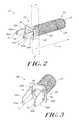
- the housing component 12which is adapted to receive a portion of the elongate member 16, is shown in more detail in FIG. 2, and includes a proximal end 70, a distal end 72, and an inner lumen 14 or bore extending therebetween.
- the housing component 12can have a variety of shapes, but is preferably cylindrical in shape and has an outer diameter oD h , inner diameter iD h (FIG. 4), and length L h .
- the outer diameter oD h , inner diameter iD h , and length L hcan vary, but preferably the outer diameter oD h is between about 6 mm and 16 mm, the inner diameter iD h is between about 3 mm and 8 mm, and the length L h is between about 20 mm and 60 mm.
- the housing component 12can optionally include a distractor member 74 protruding distally from the distal end 72, a stop member 80 formed on the distal end 72, and/or a cutting template 82 for limiting the rotation of the elongate member 16.
- the distractor member 74is effective to separate and position adjacent bone structures, and can be mated to or formed integrally with the housing component 12.
- the distractor member 74can have a variety of shapes and sizes.
- the distractor member 74includes first and second opposed members 74A, 74B adapted to be disposed between adjacent bone structures, e.g. vertebral bodies.
- Each opposed member 74A, 74Bincludes a leading, distal end 76A, 76B and a proximal end 78A, 78B mated the stop member 80 and/or housing component 12.
- the leading, distal ends 76A, 76Bcan be substantially bullet-shaped to facilitate insertion of the distractor member 74 between two adjacent vertebral bodies.
- the opposed members 74A, 74Bcan optionally be curved inward along the length L o to contour the circumferential shape of the housing component 12.
- the opposed members 74A, 74Bcan have a variety of shapes and sizes, and can be adapted to separate adjacent vertebrae by a predetermined distance. While the shape and size of the opposed members 74A, 74B can vary, preferably, the distal end 76B of each opposed member 74A, 74B has a height H 1 that is less a height H 2 of the proximal end 78A, 78B, thereby forming a distal taper. The height H 1 , H 2 of the opposed members 74A, 74B can be adjusted based on the intended use, e.g.
- each opposed member 74A, 74Bwill also vary depending on the intended use, however, the length L o is preferably between about 33 mm and 63 mm. In use, the distal taper of the opposed members 74A, 74B is effective to separate the adjacent vertebrae as the instrument 10 is inserted into the vertebral disc space.
- the stop member 80can be disposed between or formed around the opposed members 74A, 74B and the housing component 12, and is effective to limit penetration of the housing component 12 between the adjacent vertebral bodies. While the stop member 80 can have a variety of shapes, in one embodiment shown in FIG. 3 the stop member is formed from a flange member that is oriented substantially perpendicular to the longitudinal axis L of the elongate member 16 and extends radially outward from the distal end 72 of the housing component 12.
- the stop member 80can have any shape, including rectangular, square or circular, and can extend around the entire circumference of the housing component 12 or can be mated to or formed integrally with particular portions of the housing component 12. As shown in FIG.
- the stop member 80can include a concave distal surface 84 and a convex proximal surface 86 (not shown) for conforming to the anterior or posterior side of the vertebral bodies. While FIGS. 2 and 3 illustrate one particular embodiment of a stop member 80, a person having ordinary skill in the art will appreciate that a variety of different stop members 80 can be used to prevent penetration of the housing component 12 into the vertebral space.
- the housing component 12can include one or more surface protrusions (e.g., spike members, not shown) extending outward from the distal end 72 and adapted to penetrate the posterior or anterior surface of the vertebral body(s). The surface protrusions are also effective to prevent rotation of the housing component 12 with respect to the elongate member 16.
- FIG. 4illustrates another embodiment of housing component 12 having a cutting template 82 effective to limit rotation of the elongate member 16.
- the cutting template 82is in the form of a circumferential slot formed in the housing component 12 and extending over a portion of the circumference of the housing component 12.
- the size and shape of the slotdefines a cutting path for the cutting element 22 of the elongate member 16.
- the cutting path Xextends between about 80° and 120° around the circumference of the sleeve member, and more preferably extends over 90° (FIG. 4) of the circumference of the sleeve member.
- an engaging member 88 adapted to extend into the slot 82can be mated to or formed in the elongate member 16.
- the engaging member 88shown in FIG. 4, can be, for example, a pin or similar type of structure protruding from the elongate member 16, preferably in a direction perpendicular to a longitudinal axis L of the instrument 10.
- the engaging member 88can be removably attached to the elongate member 16 to allow for removal and replacement of the elongate member 16 from the housing component 12. This will allow the surgeon to select from a variety of different housing components 12 having different sized distractors 24, and different elongate members 16 having different sized cutting elements 22.
- the position of the engaging member 88 along the longitudinal axis L of the elongate member 16can be adjusted depending on the desired position of the cutting element 22 with respect to the distractor member 24. Referring back to FIG. 1, in one embodiment the engaging member 88 is positioned to cause the distal end 20 of the elongate member 16 to extend from the distal end 72 of the housing component 12.
- the elongate member 16, shown in FIG. 5,is adapted to be at least partially disposed within the inner lumen of the housing component 12.
- the elongate membercan have a generally cylindrical shape and includes a proximal end 18 and a distal end 20.
- the body of the elongate member 16is preferably rigid and extends along a longitudinal axis L.
- the diameter D e of the elongate member 16can vary along the length L e of the elongate member 16, but is preferably adapted to fit within the inner lumen of the housing such that the elongate member 16 can be rotated along the longitudinal axis L .
- the elongate memberhas a diameter D e between about 3 mm and 8 mm, and has a length L e between about 100 mm and 200 mm.
- D ediameter between about 3 mm and 8 mm
- L elength between about 100 mm and 200 mm
- the proximal end 18 of the elongate member 16can include a gripping surface 28 or handle for grasping and rotating the elongate member 16.
- the gripping surface 28can be a knurled surface to facilitate manual rotation of the elongate member.
- the gripping surface 28can be adapted to mate with a driver device effective to rotate the elongate member.
- the handlecan have a variety of shapes and sizes, and devices known in the art for rotating the elongate member can be mated to or disposed within the handle.
- the distal end 20 of the elongate member 16includes a cutting element 22 which is effective to remove portions of adjacent bone structures, such as adjacent vertebrae.
- the cutting element 22can include first and second blade members 30, 32 mated to or formed integrally with the elongate member 16. The shape, size, and position of each blade member 30, 32 can be adapted based on the intended use.
- the blade members 30, 32are generally rectangular in shape and include a distal end 34, 36, a proximal end 38, 40, and a cutting surface 42, 44 that extends between the proximal and distal ends.
- the cutting surface 42, 44 of each blade member 30, 32can be shaped to match the orientation of the vertebral endplate on which the instrument 10 is intended to be used.
- the cutting surfaces 42, 44can be convex or concave, or can have an irregular shape adapted to match specific vertebral endplates.
- each cutting surface 42, 44is angularly oriented such that a proximal portion 50, 52 of the cutting surface 42, 44 is disposed at a greater distance from the longitudinal axis L than a distal portion 54, 56 of the cutting surface 42, 44. This is particularly useful for preparing adjacent vertebrae located along the lower portion of the spinal column since the vertebral bodies are disposed at a greater angle with respect to one another.
- each cutting surface 42, 44is disposed at an angle A from the longitudinal axis L between about 1° and 5°, and preferably at an angle A of about 3.5°.
- the embodiment shown in FIG. 6is adapted for use with an anterior-surgical approach.
- each cutting surfacecan be disposed at a greater distance from the longitudinal axis than the proximal portion of each cutting surface.
- each blade member 30, 32can also be adapted to remove bone upon rotation of the elongate member in both a first direction, and in a second, opposite direction.
- blade member 30is shown having a distal surface 42 with first and second opposed leading edges 46, 48.
- the leading edges 46, 48extend outward from the distal surface 42 to form a substantially sharpened edge effective to penetrate and remove a portion of the vertebral endplate upon rotation of the elongate member 16 in both a first direction and in a second, opposite direction.
- each blade member 30, 32can also vary, but preferably each blade member 30, 32 is disposed radially outward from the elongate member 16 at a predetermined distance D b (FIG. 6), which extends from the elongate member 16 to the distal surface 42, 44.
- the distance D bcan vary along a length L b of each distal surface 42, 44 and is determinative of the amount of bone to be removed from each endplate.
- the distance D bis preferably between about 1 mm and 5 mm, and more preferably is about 2 mm.
- the longitudinal length L b and width W b of the blade members 30, 32can also vary depending on the intended use.
- each cutting surface 42, 44has a width W b between about 2 mm and 4 mm, and more preferably about 3 mm.
- the length L b of the blade members 30, 32will vary based on the size of the vertebral endplate to be prepared, but is preferably between about 2 mm and 6 mm, and more preferably about 5 mm.
- the length L b , width W b , and distance D bcan be adapted to removed a predetermined amount of bone from each endplate.
- the blade members 30, 32are adapted to remove between about 10% and 50% of bone from each endplate, and more preferably about 25% of bone from each endplate.
- each endplate 58, 60includes an anterior region 62, 64 having first and second lateral halves 62A, 62B, 64A, 64B, and a posterior region 66, 68 having first and second lateral halves 66A, 66B, 68A, 68B, respectively.
- the blade members 30, 32can be adapted to remove bone in one of more regions of each vertebral endplate.
- the first blade membercan be disposed distal of and offset from the second blade member 32 (FIG. 1) to remove diagonally opposed regions of bone from adjacent vertebral endplates.
- the first blade member 30will remove a portion of bone from the posterior region 68 of one of the superior or inferior endplates 58, 60
- the second blade member 32will remove a portion of bone from the anterior region 62 of the opposed endplate 58, 60.
- the removed portions of bone from the endplates of the vertebral bodiesare diagonally opposed. This is particularly important to maintain the structural integrity of the vertebrae.
- the distal end 36 of the second blade member 32is disposed proximal of the distal end 34 of the first blade member 30.
- the amount and region of bone removed from the anterior or posterior region of each endplatecan further be adjusted. For example, where the elongate member 16 is rotated 180° in a first direction, and then 180° in a second, opposite direction, the first blade member 30 will remove bone from only one of the two adjacent endplates 58, 60, and the second blade member 32 will only remove bone from the opposed endplate. Alternatively, where the elongate member 16 is rotated 360° in a first direction, the first and second blade members 30, 32 will remove bone from each endplate 58, 60.
- the elongate member 16is rotated only 90° in a first direction, and 90° in a second, opposite direction. As a result, only a portion of bone from part of the anterior 62, 62 or posterior 66, 68 region of each endplate 58, 60 is removed. As shown in FIG. 8, the elongate member 16 is rotated to cause the first blade member 30 to remove a portion of bone from the second lateral half 68B of the posterior region 68 of the inferior endplate 60, and the second blade member 32 to remove a portion of bone from the first lateral half 62A of the anterior region 62 of the superior endplate 58.
- FIG. 9illustrates a top view of the endplates 58, 60 disposed adjacent to one another.
- the portion of removed bone 62A from the superior endplate 58is disposed diagonally across a quadrant from the portion of removed bone 68B from the inferior endplate 60. Only about 25% of bone from each endplate 58, 60 is removed.
- the annulus of the vertebraeis exposed to allow blood to flow therethrough, yet the structural integrity of each endplate 58, 60 is maintained.
- the weight bearing load of each endplate on the implant(not shown) is distributed across the surface area of the endplates 58, 60, thereby reducing the risk of the vertebral bodies collapsing around the implant.
- the surgical bone preparation instrumentis effective for preparing adjacent bone structures, but is preferably used for preparing endplates of adjacent vertebral bodies.
- the instrument 10is inserted between the vertebrae 58, 60, as shown in FIG. 10.
- the distractor member 24is used to separate the vertebrae 58, 60 and position the cutting element 22 between the vertebral endplates.
- the stop member 80will abut the exterior surface 90 of the vertebrae 58, 60, thereby preventing over insertion of the instrument 10.
- the elongate member 16is rotated to remove a portion of bone from each endplate 58, 60, as shown in FIG. 11.
Landscapes
- Health & Medical Sciences (AREA)
- Surgery (AREA)
- Life Sciences & Earth Sciences (AREA)
- Biomedical Technology (AREA)
- Medical Informatics (AREA)
- Orthopedic Medicine & Surgery (AREA)
- Oral & Maxillofacial Surgery (AREA)
- Engineering & Computer Science (AREA)
- Dentistry (AREA)
- Heart & Thoracic Surgery (AREA)
- Nuclear Medicine, Radiotherapy & Molecular Imaging (AREA)
- Molecular Biology (AREA)
- Animal Behavior & Ethology (AREA)
- General Health & Medical Sciences (AREA)
- Public Health (AREA)
- Veterinary Medicine (AREA)
- Prostheses (AREA)
- Surgical Instruments (AREA)
Abstract
Description
The present invention relates to instruments and methods for preparing adjacentbone structures, and more particularly, to instruments and methods for preparingadjacent vertebral endplates prior to a spinal fusion procedure.
Advancing age, as well as injuries, can lead to changes in the various bones,discs, joints and ligaments of the body. In particular, these changes can manifestthemselves in the form of damage or degeneration of an intervertebral disc, the result ofwhich is mild to severe chronic back pain. Intervertebral discs serve as "shock"absorbers for the spinal column, absorbing pressure delivered to the spinal column.Additionally, they maintain the proper anatomical separation between two adjacentvertebra. This separation is necessary for allowing both the afferent and efferent nervesto exit and enter, respectively, the spinal column.
Treatment for a diseased or damaged disc can involve the removal of the affecteddisc and subsequent fusion of the opposing vertebra to one another. Spinal fusionconsists of fusing the adjacent vertebrae through the disc space (the space previouslyoccupied by the spinal disc interposed between the adjacent vertebral bodies).Typically, a fusion cage and/or bone graft is placed into the disc space to position thevertebrae apart so as to create more space for the nerves, to restore the angularrelationship between the adjacent vertebrae to be fused, and to provide for material thatcan participate in and promote the fusion process.
In general, the ability to achieve bone fusion appears to be related to certainfactors, such as the quality and quantity of bone graft material present, the surface areaavailable for the fusion to occur over, and the stability of the construct being fused. Thefusion cage and/or bone graft should, for example, occupy a significant portion of thedisc space to provide a large surface area over which fusion can occur, and shouldcontour the vertebral endplates adjacent the disc space to provide stability and furtherpromote fusion. The fusion cage and/or bone graft used for the purpose of interbodyfusion, however, can not always be shaped to precisely fit the complex contours of the vertebral endplates adjacent the disc space. Accordingly, rather than shaping the fusioncage to contour the disc space, procedures have been developed for removing at least aportion of the outermost layer of the vertebral endplates. This is effective to causebleeding to occur, and thereby to encourage the fusion and invoke the healing process ofthe bone.
Since the vertebral endplates are generally quite strong, it is desirable to preservethis structure even while removing portions of the bone. In the past, anterior interbodyfusion would be performed by removing at least a portion of the intervertebral disc andthen utilizing hand held instruments including, for example, osteotomes, chisels,curettes, rongeurs, and burrs to scrape and shape the vertebral endplates and vertebralbone stock. Such operations would be performed generally by working on one vertebraat a time, independent of the position of the adjacent vertebra.
Endplate preparation procedures can present the surgeon with several challenges.For example, the vertebral endplates should be prepared to match the implant to providethe greatest possible interface congruity between the endplates and the implant, as wellas provide for the optimal contact surface, enhanced fusion area, and enhanced graft andconstruct stability. In order to achieve this, the amount of bone removed must be to aspecified depth and width. Excess removal or penetration of the vertebral endplate canresult in a weakening of the structural integrity of the vertebrae, thereby potentiallycausing the vertebral bodies to collapse around the fusion implant. Conversely, wherean insufficient amount of bone is removed, blood flow may be very limited therebyhindering fusion of the implant to the vertebrae. This could potentially result inmisalignment of the implant due to shifting.
Accordingly, there is a need for instruments and methods for the safe andeffective preparation of adjacent vertebral endplates prior to a spinal fusion procedure.
The present invention provides a surgical bone preparation instrument usefulduring interbody fusion procedures, and methods of use thereof. The surgical bonepreparation instrument is effective to remove a desired portion of bone from adjacentbone structures, such as vertebral endplates, to allow a sufficient amount of blood toflow to the implant, while maintaining the structural integrity of the vertebrae.
In general, the surgical bone preparation instrument includes a housing or sleevemember having an inner lumen or bore formed between a proximal end and a distal end.At least one distractor member protrudes distally from the distal end of the housingmember and is adapted to be disposed between adjacent bone structures. The instrumentfurther includes an elongate member, or rotatable cutting member, having a proximalend and a distal end. The proximal end of the elongate member can include a grippingsurface, such as a handle, and the distal end of the elongate member includes a cuttingelement. The elongate member is adapted to be at least partially disposed within theinner lumen of the housing, such that the cutting element is positioned proximate to thedistractor member. In use, the elongate member is rotated with respect to the housing,thereby causing the cutting element to penetrate and remove bone from the adjacentbone structures.
In one embodiment, the cutting member includes first and second opposed blademembers effective to remove a portion of a surface of a bone structure upon rotation ofthe elongate member. The blade members are longitudinally oriented and include distaland proximal ends with a cutting surface extending therebetween. The cutting surface ofeach blade member can include first and second opposed leading edges which areeffective to remove a portion of bone upon rotation of the elongate member in both afirst direction and a second, opposite direction. The size, shape, and position of theblade members can be adapted to remove a specific region and amount of bone from thevertebral endplates. For example, the first blade member can be disposed distal of thesecond blade member to remove diametrically opposed regions of bone from theendplates.
In another embodiment, the instrument can include a rotation limiting elementwhich defines a cutting path for the cutting member. The rotation limiting element canbe formed from a slot disposed in the housing and extending over a portion of acircumference of the housing. An engaging element, such as a pin member, can bedisposed on the rotatable cutting member such that the pin member is adapted to bedisposed within the slot in the housing. In use, the shape of the slot defines a cuttingpath extending over a portion of the circumference of the sleeve member. For example,where the slot extends over 90° of the circumference of the housing, the elongatemember can be rotated 90° in a first direction, and 90° in a second, opposite direction thereby causing the first blade member to remove bone from a first vertebral endplate,and the second blade member to remove bone from a second, adjacent vertebralendplate.
In yet another embodiment, the housing component can include a stop membereffective to prevent the housing from entering a space between adjacent bone structures.By way of non-limiting example, the stop member can be formed from a flange orshoulder that extends radially outward from the housing and is oriented substantiallyperpendicular to a longitudinal axis of the instrument.
In order to prepare adjacent bone structures, and more specifically the endplatesof adjacent vertebral bodies, the distractor of the surgical bone preparation instrument isinserted between the bone structures to separate the adjacent vertebrae. The elongatemember is then rotated, thereby causing the cutting element to remove a portion of bonefrom the endplate of each vertebra.
The invention will be more fully understood from the following detaileddescription taken in conjunction with the accompanying drawings, in which:
The present invention provides a surgical bone preparation instrument that iseffective to prepare the surface of adjacent bone structures, and more particularly toremove a predetermined portion of bone from the vertebral endplates of adjacentvertebral bodies to expose the nucleus of the vertebral body. The removed portion of theendplates allows a sufficient amount of blood to flow therethrough and into an implantsubsequently positioned between the adjacent vertebrae, thereby enhancing bone growthand facilitating more rapid and secure fusion of the implant with the adjacent vertebrae.
Referring to FIG. 1, thebone preparation instrument 10 according to the presentinvention generally includes two components: ahousing component 12 having an innerlumen 14 (FIG. 2) formed therein, and anelongate member 16 at least partially androtatably disposed within theinner lumen 14 of thehousing 12. Thehousing 12 canoptionally include at least onedistractor member 24 adapted to be disposed betweenadjacent bone structures, and theelongate member 16 can include at least one cuttingelement 22 positioned between thedistractor member 24 and effective to removeportions of adjacent bone structures.
Thehousing component 12, which is adapted to receive a portion of theelongatemember 16, is shown in more detail in FIG. 2, and includes aproximal end 70, adistalend 72, and aninner lumen 14 or bore extending therebetween. Thehousing component 12 can have a variety of shapes, but is preferably cylindrical in shape and has an outerdiameter oDh, inner diameter iDh (FIG. 4), and length Lh. The outer diameter oDh, innerdiameter iDh, and length Lh can vary, but preferably the outer diameter oDh is betweenabout 6 mm and 16 mm, the inner diameter iDh is between about 3 mm and 8 mm, andthe length Lh is between about 20 mm and 60 mm. Thehousing component 12 canoptionally include a distractor member 74 protruding distally from thedistal end 72, astop member 80 formed on thedistal end 72, and/or a cuttingtemplate 82 for limitingthe rotation of theelongate member 16.
The distractor member 74 is effective to separate and position adjacent bonestructures, and can be mated to or formed integrally with thehousing component 12.The distractor member 74 can have a variety of shapes and sizes. In one embodiment, asshown in FIGS. 2 and 3, the distractor member 74 includes first and secondopposedmembers opposed member distal end 76A,76B and aproximal end 78A, 78B mated thestop member 80 and/orhousing component 12. The leading, distal ends 76A, 76B can be substantially bullet-shaped to facilitateinsertion of the distractor member 74 between two adjacent vertebral bodies. Theopposed members housing component 12.
Theopposed members opposed members opposed member proximalend 78A, 78B, thereby forming a distal taper. The heightH1, H2 of theopposedmembers opposed member opposed members instrument 10 is inserted intothe vertebral disc space.
Thestop member 80 can be disposed between or formed around theopposedmembers housing component 12, and is effective to limit penetrationof thehousing component 12 between the adjacent vertebral bodies. While thestopmember 80 can have a variety of shapes, in one embodiment shown in FIG. 3 the stopmember is formed from a flange member that is oriented substantially perpendicular tothe longitudinal axis L of theelongate member 16 and extends radially outward from thedistal end 72 of thehousing component 12. Thestop member 80 can have any shape,including rectangular, square or circular, and can extend around the entire circumferenceof thehousing component 12 or can be mated to or formed integrally with particularportions of thehousing component 12. As shown in FIG. 3, thestop member 80 caninclude a concavedistal surface 84 and a convex proximal surface 86 (not shown) forconforming to the anterior or posterior side of the vertebral bodies. While FIGS. 2 and 3illustrate one particular embodiment of astop member 80, a person having ordinary skillin the art will appreciate that a variety ofdifferent stop members 80 can be used toprevent penetration of thehousing component 12 into the vertebral space. By way ofnon-limiting example, thehousing component 12 can include one or more surfaceprotrusions (e.g., spike members, not shown) extending outward from thedistal end 72and adapted to penetrate the posterior or anterior surface of the vertebral body(s). Thesurface protrusions are also effective to prevent rotation of thehousing component 12with respect to theelongate member 16.
FIG. 4 illustrates another embodiment ofhousing component 12 having a cuttingtemplate 82 effective to limit rotation of theelongate member 16. The cuttingtemplate 82 is in the form of a circumferential slot formed in thehousing component 12 andextending over a portion of the circumference of thehousing component 12. The sizeand shape of the slot defines a cutting path for the cuttingelement 22 of theelongatemember 16. Preferably, the cutting pathX extends between about 80° and 120° aroundthe circumference of the sleeve member, and more preferably extends over 90° (FIG. 4)of the circumference of the sleeve member.
In order to limit rotation of theelongate member 16, an engagingmember 88adapted to extend into theslot 82 can be mated to or formed in theelongate member 16.The engagingmember 88, shown in FIG. 4, can be, for example, a pin or similar type ofstructure protruding from theelongate member 16, preferably in a directionperpendicular to a longitudinal axis L of theinstrument 10. The engagingmember 88can be removably attached to theelongate member 16 to allow for removal andreplacement of theelongate member 16 from thehousing component 12. This willallow the surgeon to select from a variety ofdifferent housing components 12 havingdifferentsized distractors 24, and differentelongate members 16 having differentsizedcutting elements 22. The position of the engagingmember 88 along the longitudinalaxisL of theelongate member 16 can be adjusted depending on the desired position ofthe cuttingelement 22 with respect to thedistractor member 24. Referring back to FIG.1, in one embodiment the engagingmember 88 is positioned to cause thedistal end 20 oftheelongate member 16 to extend from thedistal end 72 of thehousing component 12.
While the present invention describes a pin and slot-type arrangement, a personhaving ordinary skill in the art will appreciate that a variety of different rotation limitingelements can be used, such as, for example, a tongue and groove joint, a dove tailconnection, or similar type of arrangement.
Theelongate member 16, shown in FIG. 5, is adapted to be at least partiallydisposed within the inner lumen of thehousing component 12. As shown, the elongatemember can have a generally cylindrical shape and includes aproximal end 18 and adistal end 20. The body of theelongate member 16 is preferably rigid and extends alonga longitudinal axisL. The diameter De of theelongate member 16 can vary along thelength Le of theelongate member 16, but is preferably adapted to fit within the innerlumen of the housing such that theelongate member 16 can be rotated along thelongitudinal axisL. In a preferred embodiment, the elongate member has a diameter Debetween about 3 mm and 8 mm, and has a length Le between about 100 mm and 200mm. A person having ordinary skill in the art will appreciate that theelongate member 16 can have a variety of shapes and sizes.
Theproximal end 18 of theelongate member 16 can include agripping surface 28 or handle for grasping and rotating theelongate member 16. In one embodiment, thegrippingsurface 28 can be a knurled surface to facilitate manual rotation of the elongate member. Alternatively, or in addition, the grippingsurface 28 can be adapted to matewith a driver device effective to rotate the elongate member. A person having ordinaryskill in the art will readily appreciate that the handle can have a variety of shapes andsizes, and devices known in the art for rotating the elongate member can be mated to ordisposed within the handle.
Thedistal end 20 of theelongate member 16 includes a cuttingelement 22 whichis effective to remove portions of adjacent bone structures, such as adjacent vertebrae.The cuttingelement 22 can include first andsecond blade members elongate member 16. The shape, size, and position of eachblade member
As shown in FIGS. 5 and 6, theblade members distal end proximal end surface surface blade member instrument 10 is intended to be used. For example, the cutting surfaces 42, 44can be convex or concave, or can have an irregular shape adapted to match specificvertebral endplates.
In the embodiment illustrated in FIG. 6, each cuttingsurface proximal portion surface distal portion surface surface
The cuttingsurface blade member blade member 30 is shown having adistal surface 42 with first and second opposed leadingedges edges distal surface 42 to form a substantially sharpened edgeeffective to penetrate and remove a portion of the vertebral endplate upon rotation of theelongate member 16 in both a first direction and in a second, opposite direction.
The size of eachblade member blademember elongate member 16 at apredetermined distance Db (FIG. 6), which extends from theelongate member 16 to thedistal surface distal surface blade members surface blade members blade members
While the size and shape of theblade members blade members elongate member 16, as well as the degree of rotation of theelongate member 16, is determinative of the exact location of bone to be removed. Forillustration purposes, superior andinferior endplates endplate lateral halves posterior region lateral halves blade members
By way of non-limiting example, the first blade member can be disposed distalof and offset from the second blade member 32 (FIG. 1) to remove diagonally opposedregions of bone from adjacent vertebral endplates. Assuming an anterior surgicalapproach is used, where thefirst blade member 30 is disposed distally to thesecondblade member 32, thefirst blade member 30 will remove a portion of bone from theposterior region 68 of one of the superior orinferior endplates secondblade member 32 will remove a portion of bone from the anterior region 62 of theopposedendplate distal end 36 of thesecond blade member 32 is disposed proximal of thedistal end 34 of thefirst blademember 30. As a result, the removed portions of bone from the endplates of thevertebral bodies are non-contacting or non-adjacent.
By varying the degree of rotation, e.g. with the rotation limiting element orcuttingtemplate 82, the amount and region of bone removed from the anterior orposterior region of each endplate can further be adjusted. For example, where theelongate member 16 is rotated 180° in a first direction, and then 180° in a second,opposite direction, thefirst blade member 30 will remove bone from only one of the twoadjacent endplates second blade member 32 will only remove bone fromthe opposed endplate. Alternatively, where theelongate member 16 is rotated 360° in afirst direction, the first andsecond blade members endplate
In a preferred embodiment, theelongate member 16 is rotated only 90° in a firstdirection, and 90° in a second, opposite direction. As a result, only a portion of bonefrom part of the anterior 62, 62 orposterior endplate elongate member 16 is rotated to cause thefirst blademember 30 to remove a portion of bone from the secondlateral half 68B of theposteriorregion 68 of theinferior endplate 60, and thesecond blade member 32 to remove aportion of bone from the firstlateral half 62A of the anterior region 62 of thesuperiorendplate 58.
The effect of rotating theelongate member 16 only 90° in each of a first directionand a second, opposite direction is shown in FIG. 9, which illustrates a top view of theendplates bone 62A from thesuperior endplate 58 is disposed diagonally across a quadrant fromthe portion of removedbone 68B from theinferior endplate 60. Only about 25% ofbone from eachendplate endplate endplates
In use, the surgical bone preparation instrument according to the presentinvention is effective for preparing adjacent bone structures, but is preferably used forpreparing endplates of adjacent vertebral bodies. In general, once the disc between twoadjacent vertebrae instrument 10 is inserted between thevertebrae distractor member 24 is used to separate thevertebrae element 22 between the vertebral endplates. Thestopmember 80 will abut theexterior surface 90 of thevertebrae instrument 10. Once fully inserted, theelongate member 16 isrotated to remove a portion of bone from eachendplate
One of ordinary skill in the art will appreciate further features and advantages ofthe invention based on the above-described embodiments. Accordingly, the invention isnot to be limited by what has been particularly shown and described, except as indicatedby the appended claims. All publications and references cited herein are expresslyincorporated herein by reference in their entirety.
Claims (30)
- A surgical bone preparation instrument, comprising:a sleeve member having a proximal end, a distal end, and an inner lumen formedtherein, the sleeve member having at least one distractor member protruding distallyfrom the distal end and adapted to be disposed between adjacent bone structures; andan elongate member at least partially rotatably disposed within the sleevemember, the elongate member having a proximal end and a distal end with at least onecutting member disposed on a portion of the distal end.
- The surgical bone preparation instrument of claim 1, wherein the at least onecutting member comprises opposed first and second blade members.
- The surgical bone preparation instrument of claim 2, wherein the first and secondblade members are each longitudinally oriented having a distal end and a proximal endwith a cutting surface extending therebetween, the distal end of the second blademember being disposed proximal of the distal end of the first blade member.
- The surgical bone preparation instrument of claim 3, wherein the proximal end ofthe first blade member is disposed distal of the distal end of the second blade member.
- The surgical bone preparation instrument of claim 2, wherein the first and secondblade members are each longitudinally oriented having a distal end and a proximal endwith a cutting surface extending therebetween, each cutting surface having first andsecond opposed leading edges adapted to remove a portion of a surface of a bonestructure upon rotation of the elongate member in a first direction and a second, oppositedirection.
- The surgical bone preparation instrument of claim 3, wherein the first and secondblade members of the elongate member extend beyond the distal end of the sleevemember and are disposed adjacent to the at least one distractor member.
- The surgical bone preparation instrument of claim 1, wherein the proximal end ofthe elongate member includes a gripping element.
- The surgical bone preparation instrument of claim 7, wherein the grippingelement is a knurled surface.
- The surgical bone preparation instrument of claim 1, wherein the distal end ofthe sleeve member includes a stop member adapted to limit penetration of the instrumentbetween adjacent bone structures.
- The surgical bone preparation instrument of claim 9, wherein the stop membercomprises a flange member that is oriented substantially perpendicular to a longitudinalaxis of the instrument, the flange member extending radially outward from the sleevemember.
- The surgical bone preparation instrument of claim 10, wherein the at least onedistractor member comprises first and second opposed members that extend distallyfrom the stop member, the opposed members being adapted to be disposed betweenadjacent bone structures for separating the adjacent bone structures by a predetermineddistance.
- The surgical bone preparation instrument of claim 11, wherein the first andsecond opposed members each include a tapered distal end to facilitate insertion of thefirst and second opposed members between adjacent bone structures.
- The surgical bone preparation instrument of claim 1, further comprising a cuttingtemplate having a circumferential slot formed in the sleeve member and extending overa portion of a circumference of the sleeve member, and an engaging element extendingfrom the elongate member and into the circumferential slot in the sleeve member, thecutting template being effective to limit rotation of the elongate member.
- The surgical bone preparation instrument of claim 13, wherein the slot defines acutting path extending over a range of between about 80° and 120° around a portion ofthe circumference of the sleeve member.
- The surgical bone preparation instrument of claim 14, wherein the cutting pathextends over a range of about 90° around a portion of the circumference of the sleevemember.
- A surgical bone preparation instrument, comprising:a housing component having a proximal end and a distal end with a boreextending between the proximal and distal ends;a distractor protruding distally from the distal end of the housing component; anda rotatable cutting member, a portion of which is disposed within the bore of thehousing component, the rotatable cutting element having a proximal handle portion anda distal cutting portion with at least one cutting element disposed thereon.
- The surgical bone preparation instrument of claim 16, wherein a portion of therotatable cutting member is removably and replaceably disposed within the bore of thehousing component.
- The surgical bone preparation instrument of claim 16, wherein the rotatablecutting member has a body portion with proximal and distal ends and a longitudinal axisextending therebetween, and wherein the at least one cutting element comprises first andsecond blade members extending radially outward from the distal end of the bodyportion.
- The surgical bone preparation instrument of claim 18, wherein the distractor isadapted to be disposed between adjacent bone structures, and the first and second blademembers are adapted to remove a portion of the adjacent bone structures upon rotationof the elongate member in a first direction and in a second, opposite direction.
- The surgical bone preparation instrument of claim 18, wherein the first blademember is opposed to and offset with respect to the second blade member.
- The surgical bone preparation instrument of claim 20, wherein the first andsecond blade members each include at least one cutting surface angularly oriented suchthat a proximal portion of the cutting surface is disposed a greater distance from thelongitudinal axis than a distal portion of the cutting surface.
- The surgical bone preparation instrument of claim 21, wherein the at least onecutting surface of the first and second blade members are disposed radially outward fromthe body portion of the rotatable cutting member at a distance of between about 1mmand 5 mm.
- The surgical bone preparation instrument of claim 22, wherein the at least onecutting surface of the first and second blade members are disposed radially outward fromthe body portion of the rotatable cutting member at a distance of 2 mm.
- The surgical bone preparation instrument of claim 16, wherein the distractorcomprises first and second opposed members each having a proximal end and a distalend, the proximal end being mated to the housing component and the distal end beingsubstantially bullet-shaped.
- The surgical bone preparation instrument of claim 16, wherein the instrument isadapted to be disposed between adjacent bone structures, and wherein the distal end ofthe housing includes a shoulder for preventing the housing from penetrating a spacebetween the adjacent bone structures.
- The surgical bone preparation instrument of claim 25, wherein the adjacent bonestructures are vertebrae.
- The surgical bone preparation instrument of claim 16, wherein the housingcomponent is substantially cylindrical and includes a rotation limiting element defining acutting path for the at least one cutting element.
- The surgical bone preparation instrument of claim 27, wherein the rotationlimiting element comprises a circumferential slot formed in the housing and extendingover a portion of a circumference of the housing.
- The surgical bone preparation instrument of claim 28, wherein the rotatablecutting member includes a pin member disposed on the rotatable cutting member andextending radially therefrom, the pin member adapted to be disposed within thecircumferential slot in the housing.
- The surgical bone preparation instrument of any one of claims 1 to 29, for usein surgery.
Applications Claiming Priority (2)
| Application Number | Priority Date | Filing Date | Title |
|---|---|---|---|
| US921055 | 2001-08-02 | ||
| US09/921,055US6682534B2 (en) | 2001-08-02 | 2001-08-02 | Endplate preparation instrument and associated method |
Publications (2)
| Publication Number | Publication Date |
|---|---|
| EP1283026A2true EP1283026A2 (en) | 2003-02-12 |
| EP1283026A3 EP1283026A3 (en) | 2003-09-17 |
Family
ID=25444852
Family Applications (1)
| Application Number | Title | Priority Date | Filing Date |
|---|---|---|---|
| EP02255394AWithdrawnEP1283026A3 (en) | 2001-08-02 | 2002-08-01 | Vertebral endplate preparation instrument |
Country Status (4)
| Country | Link |
|---|---|
| US (1) | US6682534B2 (en) |
| EP (1) | EP1283026A3 (en) |
| JP (1) | JP2003102741A (en) |
| CA (1) | CA2396313A1 (en) |
Cited By (36)
| Publication number | Priority date | Publication date | Assignee | Title |
|---|---|---|---|---|
| WO2004089224A3 (en)* | 2003-03-31 | 2004-12-02 | Depuy Spine Inc | Method and apparatus for artificial disc insertion |
| EP1570813A1 (en)* | 2004-03-05 | 2005-09-07 | Cervitech, Inc. | Cervical intervertebral disc prosthesis with anti-luxation means, and instrument |
| WO2006033067A3 (en)* | 2004-09-23 | 2007-05-18 | Spine Solutions Inc | System and method for an intervertebral implant |
| US7625380B2 (en) | 2004-07-21 | 2009-12-01 | Warsaw Orthopedic, Inc. | Dual distractor inserter |
| US7914535B2 (en) | 2003-10-23 | 2011-03-29 | Trans1 Inc. | Method and apparatus for manipulating material in the spine |
| US8845733B2 (en) | 2010-06-24 | 2014-09-30 | DePuy Synthes Products, LLC | Lateral spondylolisthesis reduction cage |
| US9226764B2 (en) | 2012-03-06 | 2016-01-05 | DePuy Synthes Products, Inc. | Conformable soft tissue removal instruments |
| CN104688343B (en)* | 2013-12-09 | 2017-05-24 | 苏州点合医疗科技有限公司 | End plate cleaning equipment for digital spinal surgeries |
| US9814598B2 (en) | 2013-03-14 | 2017-11-14 | Quandary Medical, Llc | Spinal implants and implantation system |
| US9931224B2 (en) | 2009-11-05 | 2018-04-03 | DePuy Synthes Products, Inc. | Self-pivoting spinal implant and associated instrumentation |
| US10022245B2 (en) | 2012-12-17 | 2018-07-17 | DePuy Synthes Products, Inc. | Polyaxial articulating instrument |
| US10966843B2 (en) | 2017-07-18 | 2021-04-06 | DePuy Synthes Products, Inc. | Implant inserters and related methods |
| US11045331B2 (en) | 2017-08-14 | 2021-06-29 | DePuy Synthes Products, Inc. | Intervertebral implant inserters and related methods |
| US11344424B2 (en) | 2017-06-14 | 2022-05-31 | Medos International Sarl | Expandable intervertebral implant and related methods |
| US11369490B2 (en) | 2011-03-22 | 2022-06-28 | DePuy Synthes Products, Inc. | Universal trial for lateral cages |
| US11426290B2 (en) | 2015-03-06 | 2022-08-30 | DePuy Synthes Products, Inc. | Expandable intervertebral implant, system, kit and method |
| US11432942B2 (en) | 2006-12-07 | 2022-09-06 | DePuy Synthes Products, Inc. | Intervertebral implant |
| US11446156B2 (en) | 2018-10-25 | 2022-09-20 | Medos International Sarl | Expandable intervertebral implant, inserter instrument, and related methods |
| US11446155B2 (en) | 2017-05-08 | 2022-09-20 | Medos International Sarl | Expandable cage |
| US11452607B2 (en) | 2010-10-11 | 2022-09-27 | DePuy Synthes Products, Inc. | Expandable interspinous process spacer implant |
| US11497619B2 (en) | 2013-03-07 | 2022-11-15 | DePuy Synthes Products, Inc. | Intervertebral implant |
| US11510788B2 (en) | 2016-06-28 | 2022-11-29 | Eit Emerging Implant Technologies Gmbh | Expandable, angularly adjustable intervertebral cages |
| US11596522B2 (en) | 2016-06-28 | 2023-03-07 | Eit Emerging Implant Technologies Gmbh | Expandable and angularly adjustable intervertebral cages with articulating joint |
| US11602438B2 (en) | 2008-04-05 | 2023-03-14 | DePuy Synthes Products, Inc. | Expandable intervertebral implant |
| US11607321B2 (en) | 2009-12-10 | 2023-03-21 | DePuy Synthes Products, Inc. | Bellows-like expandable interbody fusion cage |
| US11612491B2 (en) | 2009-03-30 | 2023-03-28 | DePuy Synthes Products, Inc. | Zero profile spinal fusion cage |
| US11622868B2 (en) | 2007-06-26 | 2023-04-11 | DePuy Synthes Products, Inc. | Highly lordosed fusion cage |
| US11654033B2 (en) | 2010-06-29 | 2023-05-23 | DePuy Synthes Products, Inc. | Distractible intervertebral implant |
| US11737881B2 (en) | 2008-01-17 | 2023-08-29 | DePuy Synthes Products, Inc. | Expandable intervertebral implant and associated method of manufacturing the same |
| US11752009B2 (en) | 2021-04-06 | 2023-09-12 | Medos International Sarl | Expandable intervertebral fusion cage |
| US11806245B2 (en) | 2020-03-06 | 2023-11-07 | Eit Emerging Implant Technologies Gmbh | Expandable intervertebral implant |
| US11850160B2 (en) | 2021-03-26 | 2023-12-26 | Medos International Sarl | Expandable lordotic intervertebral fusion cage |
| US11872139B2 (en) | 2010-06-24 | 2024-01-16 | DePuy Synthes Products, Inc. | Enhanced cage insertion assembly |
| USRE49973E1 (en) | 2013-02-28 | 2024-05-21 | DePuy Synthes Products, Inc. | Expandable intervertebral implant, system, kit and method |
| US12090064B2 (en) | 2022-03-01 | 2024-09-17 | Medos International Sarl | Stabilization members for expandable intervertebral implants, and related systems and methods |
| US12440346B2 (en) | 2023-03-31 | 2025-10-14 | DePuy Synthes Products, Inc. | Expandable intervertebral implant |
Families Citing this family (28)
| Publication number | Priority date | Publication date | Assignee | Title |
|---|---|---|---|---|
| AU2003205553A1 (en)* | 2002-02-07 | 2003-09-02 | Oticon A/S | Filter manipulator, filter, holder for a number of filter manipulators, and system comprising a filter manipulator and a holder for a filter manipulator |
| WO2004084742A1 (en)* | 2003-03-24 | 2004-10-07 | Theken Surgical Llc | Spinal implant adjustment device |
| US6945974B2 (en) | 2003-07-07 | 2005-09-20 | Aesculap Inc. | Spinal stabilization implant and method of application |
| US6945975B2 (en)* | 2003-07-07 | 2005-09-20 | Aesculap, Inc. | Bone fixation assembly and method of securement |
| US20060229627A1 (en)* | 2004-10-29 | 2006-10-12 | Hunt Margaret M | Variable angle spinal surgery instrument |
| US7806932B2 (en) | 2003-08-01 | 2010-10-05 | Zimmer Spine, Inc. | Spinal implant |
| US7179261B2 (en)* | 2003-12-16 | 2007-02-20 | Depuy Spine, Inc. | Percutaneous access devices and bone anchor assemblies |
| US11419642B2 (en) | 2003-12-16 | 2022-08-23 | Medos International Sarl | Percutaneous access devices and bone anchor assemblies |
| US7311712B2 (en)* | 2004-02-26 | 2007-12-25 | Aesculap Implant Systems, Inc. | Polyaxial locking screw plate assembly |
| US20050228380A1 (en)* | 2004-04-09 | 2005-10-13 | Depuy Spine Inc. | Instruments and methods for minimally invasive spine surgery |
| US7544208B1 (en) | 2004-05-03 | 2009-06-09 | Theken Spine, Llc | Adjustable corpectomy apparatus |
| US7429264B2 (en)* | 2004-06-15 | 2008-09-30 | Warsaw Orthopedic, Inc. | Minimally invasive deployable cutting instrument |
| US7549993B2 (en)* | 2004-06-16 | 2009-06-23 | Warsaw Orthopedic, Inc. | Constant lift cam spreader |
| US20060106395A1 (en)* | 2004-07-23 | 2006-05-18 | Cervitech, Inc. | Instrument set and method for working a cervical vertebral body |
| US20060036261A1 (en)* | 2004-08-13 | 2006-02-16 | Stryker Spine | Insertion guide for a spinal implant |
| US7763024B2 (en)* | 2004-09-23 | 2010-07-27 | Spine Solutions, Inc. | Adjustable cutting of cutout in vertebral bone |
| US7959675B2 (en)* | 2005-04-08 | 2011-06-14 | G&L Consulting, Llc | Spine implant insertion device and method |
| US20100100138A1 (en)* | 2005-09-21 | 2010-04-22 | Reynolds Joseph E | Endoscopic Insturments and Mehod for Delivery of Spinal Implant |
| US9072554B2 (en)* | 2005-09-21 | 2015-07-07 | Children's Hospital Medical Center | Orthopedic implant |
| US7918857B2 (en) | 2006-09-26 | 2011-04-05 | Depuy Spine, Inc. | Minimally invasive bone anchor extensions |
| US8641764B2 (en)* | 2006-10-11 | 2014-02-04 | G&L Consulting, Llc | Spine implant insertion device and method |
| US20080161810A1 (en)* | 2006-10-18 | 2008-07-03 | Warsaw Orthopedic, Inc. | Guide and Cutter for Contouring Facet Joints and Methods of Use |
| US20080140085A1 (en)* | 2006-12-11 | 2008-06-12 | G&L Consulting, Llc | Steerable spine implant insertion device and method |
| US8414588B2 (en)* | 2007-10-04 | 2013-04-09 | Depuy Spine, Inc. | Methods and devices for minimally invasive spinal connection element delivery |
| US8932332B2 (en)* | 2008-05-08 | 2015-01-13 | Aesculap Implant Systems, Llc | Minimally invasive spinal stabilization system |
| US20100198271A1 (en)* | 2009-02-02 | 2010-08-05 | Vincent Leone | Screw Sheath for Minimally Invasive Spinal Surgery and Method Relating Thereto |
| CA2920576A1 (en)* | 2013-08-05 | 2015-02-12 | Scott L. Blumenthal | Vertebral endplate apparatus and method |
| CN108670329B (en)* | 2018-06-22 | 2024-01-05 | 王志荣 | Vertebral endplate treatment device |
Family Cites Families (16)
| Publication number | Priority date | Publication date | Assignee | Title |
|---|---|---|---|---|
| US3554192A (en)* | 1967-07-24 | 1971-01-12 | Orthopedic Equipment Co | Medullary space drill |
| US5015247A (en) | 1988-06-13 | 1991-05-14 | Michelson Gary K | Threaded spinal implant |
| US5484437A (en) | 1988-06-13 | 1996-01-16 | Michelson; Gary K. | Apparatus and method of inserting spinal implants |
| EP0703757B1 (en) | 1988-06-13 | 2003-08-27 | Karlin Technology, Inc. | Apparatus for inserting spinal implants |
| US4988241A (en)* | 1989-09-15 | 1991-01-29 | The Boeing Company | Cutter with angled diamond inserts |
| US5190548A (en)* | 1991-04-10 | 1993-03-02 | Linvatec Corporation | Surgical reamer |
| CA2155422C (en) | 1993-02-10 | 2005-07-12 | Stephen D. Kuslich | Spinal stabilization surgical method |
| CA2199462C (en)* | 1996-03-14 | 2006-01-03 | Charles J. Winslow | Method and instrumentation for implant insertion |
| DE19780707C2 (en) | 1996-03-22 | 2002-09-12 | Sdgi Holdings Inc | Percutaneous surgery device |
| US5792044A (en) | 1996-03-22 | 1998-08-11 | Danek Medical, Inc. | Devices and methods for percutaneous surgery |
| US6159214A (en) | 1996-07-31 | 2000-12-12 | Michelson; Gary K. | Milling instrumentation and method for preparing a space between adjacent vertebral bodies |
| TW375522B (en) | 1996-10-24 | 1999-12-01 | Danek Medical Inc | Devices for percutaneous surgery under direct visualization and through an elongated cannula |
| US6004326A (en)* | 1997-09-10 | 1999-12-21 | United States Surgical | Method and instrumentation for implant insertion |
| US6174311B1 (en) | 1998-10-28 | 2001-01-16 | Sdgi Holdings, Inc. | Interbody fusion grafts and instrumentation |
| US6264703B1 (en)* | 2000-02-10 | 2001-07-24 | Janet Lynn Coope | Hair coloring composition using an inorganic peroxymonosulfate salt as an oxidation agent |
| US6540753B2 (en)* | 2001-03-23 | 2003-04-01 | Howmedica Osteonics Corp. | Instrumentation for implant insertion |
- 2001
- 2001-08-02USUS09/921,055patent/US6682534B2/ennot_activeExpired - Fee Related
- 2002
- 2002-07-29CACA002396313Apatent/CA2396313A1/ennot_activeAbandoned
- 2002-08-01EPEP02255394Apatent/EP1283026A3/ennot_activeWithdrawn
- 2002-08-01JPJP2002225149Apatent/JP2003102741A/enactivePending
Cited By (70)
| Publication number | Priority date | Publication date | Assignee | Title |
|---|---|---|---|---|
| WO2004089224A3 (en)* | 2003-03-31 | 2004-12-02 | Depuy Spine Inc | Method and apparatus for artificial disc insertion |
| US7914535B2 (en) | 2003-10-23 | 2011-03-29 | Trans1 Inc. | Method and apparatus for manipulating material in the spine |
| EP1570813A1 (en)* | 2004-03-05 | 2005-09-07 | Cervitech, Inc. | Cervical intervertebral disc prosthesis with anti-luxation means, and instrument |
| WO2005084589A1 (en)* | 2004-03-05 | 2005-09-15 | Cervitech, Inc. | Cervical intervertebral disc prosthesis comprising an anti-dislocation device and instruments |
| US7625380B2 (en) | 2004-07-21 | 2009-12-01 | Warsaw Orthopedic, Inc. | Dual distractor inserter |
| WO2006033067A3 (en)* | 2004-09-23 | 2007-05-18 | Spine Solutions Inc | System and method for an intervertebral implant |
| US11497618B2 (en) | 2006-12-07 | 2022-11-15 | DePuy Synthes Products, Inc. | Intervertebral implant |
| US11642229B2 (en) | 2006-12-07 | 2023-05-09 | DePuy Synthes Products, Inc. | Intervertebral implant |
| US11712345B2 (en) | 2006-12-07 | 2023-08-01 | DePuy Synthes Products, Inc. | Intervertebral implant |
| US11660206B2 (en) | 2006-12-07 | 2023-05-30 | DePuy Synthes Products, Inc. | Intervertebral implant |
| US11432942B2 (en) | 2006-12-07 | 2022-09-06 | DePuy Synthes Products, Inc. | Intervertebral implant |
| US11622868B2 (en) | 2007-06-26 | 2023-04-11 | DePuy Synthes Products, Inc. | Highly lordosed fusion cage |
| US11737881B2 (en) | 2008-01-17 | 2023-08-29 | DePuy Synthes Products, Inc. | Expandable intervertebral implant and associated method of manufacturing the same |
| US11712342B2 (en) | 2008-04-05 | 2023-08-01 | DePuy Synthes Products, Inc. | Expandable intervertebral implant |
| US12023255B2 (en) | 2008-04-05 | 2024-07-02 | DePuy Synthes Products, Inc. | Expandable inter vertebral implant |
| US11701234B2 (en) | 2008-04-05 | 2023-07-18 | DePuy Synthes Products, Inc. | Expandable intervertebral implant |
| US11602438B2 (en) | 2008-04-05 | 2023-03-14 | DePuy Synthes Products, Inc. | Expandable intervertebral implant |
| US11712341B2 (en) | 2008-04-05 | 2023-08-01 | DePuy Synthes Products, Inc. | Expandable intervertebral implant |
| US11617655B2 (en) | 2008-04-05 | 2023-04-04 | DePuy Synthes Products, Inc. | Expandable intervertebral implant |
| US12011361B2 (en) | 2008-04-05 | 2024-06-18 | DePuy Synthes Products, Inc. | Expandable intervertebral implant |
| US11707359B2 (en) | 2008-04-05 | 2023-07-25 | DePuy Synthes Products, Inc. | Expandable intervertebral implant |
| US11612491B2 (en) | 2009-03-30 | 2023-03-28 | DePuy Synthes Products, Inc. | Zero profile spinal fusion cage |
| US12097124B2 (en) | 2009-03-30 | 2024-09-24 | DePuy Synthes Products, Inc. | Zero profile spinal fusion cage |
| US11712349B2 (en) | 2009-11-05 | 2023-08-01 | DePuy Synthes Products, Inc. | Self-pivoting spinal implant and associated instrumentation |
| US10792166B2 (en) | 2009-11-05 | 2020-10-06 | DePuy Synthes Products, Inc. | Self-pivoting spinal implant and associated instrumentation |
| US9931224B2 (en) | 2009-11-05 | 2018-04-03 | DePuy Synthes Products, Inc. | Self-pivoting spinal implant and associated instrumentation |
| US11607321B2 (en) | 2009-12-10 | 2023-03-21 | DePuy Synthes Products, Inc. | Bellows-like expandable interbody fusion cage |
| US10405989B2 (en) | 2010-06-24 | 2019-09-10 | DePuy Synthes Products, Inc. | Lateral spondylolisthesis reduction cage |
| US11911287B2 (en) | 2010-06-24 | 2024-02-27 | DePuy Synthes Products, Inc. | Lateral spondylolisthesis reduction cage |
| US12318304B2 (en) | 2010-06-24 | 2025-06-03 | DePuy Synthes Products, Inc. | Lateral spondylolisthesis reduction cage |
| US8845733B2 (en) | 2010-06-24 | 2014-09-30 | DePuy Synthes Products, LLC | Lateral spondylolisthesis reduction cage |
| US9282979B2 (en) | 2010-06-24 | 2016-03-15 | DePuy Synthes Products, Inc. | Instruments and methods for non-parallel disc space preparation |
| US11872139B2 (en) | 2010-06-24 | 2024-01-16 | DePuy Synthes Products, Inc. | Enhanced cage insertion assembly |
| US9592063B2 (en) | 2010-06-24 | 2017-03-14 | DePuy Synthes Products, Inc. | Universal trial for lateral cages |
| US9763678B2 (en) | 2010-06-24 | 2017-09-19 | DePuy Synthes Products, Inc. | Multi-segment lateral cage adapted to flex substantially in the coronal plane |
| US9801640B2 (en) | 2010-06-24 | 2017-10-31 | DePuy Synthes Products, Inc. | Lateral spondylolisthesis reduction cage |
| US9801639B2 (en) | 2010-06-24 | 2017-10-31 | DePuy Synthes Products, Inc. | Lateral spondylolisthesis reduction cage |
| US9907560B2 (en) | 2010-06-24 | 2018-03-06 | DePuy Synthes Products, Inc. | Flexible vertebral body shavers |
| US10449057B2 (en) | 2010-06-24 | 2019-10-22 | DePuy Synthes Products, Inc. | Lateral spondylolisthesis reduction cage |
| US10588754B2 (en) | 2010-06-24 | 2020-03-17 | DePuy Snythes Products, Inc. | Lateral spondylolisthesis reduction cage and instruments and methods for non-parallel disc space preparation |
| US10646350B2 (en) | 2010-06-24 | 2020-05-12 | DePuy Synthes Products, Inc. | Multi-segment lateral cages adapted to flex substantially in the coronal plane |
| US11654033B2 (en) | 2010-06-29 | 2023-05-23 | DePuy Synthes Products, Inc. | Distractible intervertebral implant |
| US11452607B2 (en) | 2010-10-11 | 2022-09-27 | DePuy Synthes Products, Inc. | Expandable interspinous process spacer implant |
| US11369490B2 (en) | 2011-03-22 | 2022-06-28 | DePuy Synthes Products, Inc. | Universal trial for lateral cages |
| US9226764B2 (en) | 2012-03-06 | 2016-01-05 | DePuy Synthes Products, Inc. | Conformable soft tissue removal instruments |
| US10022245B2 (en) | 2012-12-17 | 2018-07-17 | DePuy Synthes Products, Inc. | Polyaxial articulating instrument |
| USRE49973E1 (en) | 2013-02-28 | 2024-05-21 | DePuy Synthes Products, Inc. | Expandable intervertebral implant, system, kit and method |
| US11497619B2 (en) | 2013-03-07 | 2022-11-15 | DePuy Synthes Products, Inc. | Intervertebral implant |
| US11850164B2 (en) | 2013-03-07 | 2023-12-26 | DePuy Synthes Products, Inc. | Intervertebral implant |
| US9814598B2 (en) | 2013-03-14 | 2017-11-14 | Quandary Medical, Llc | Spinal implants and implantation system |
| CN104688343B (en)* | 2013-12-09 | 2017-05-24 | 苏州点合医疗科技有限公司 | End plate cleaning equipment for digital spinal surgeries |
| US11426290B2 (en) | 2015-03-06 | 2022-08-30 | DePuy Synthes Products, Inc. | Expandable intervertebral implant, system, kit and method |
| US11596523B2 (en) | 2016-06-28 | 2023-03-07 | Eit Emerging Implant Technologies Gmbh | Expandable and angularly adjustable articulating intervertebral cages |
| US12433757B2 (en) | 2016-06-28 | 2025-10-07 | Eit Emerging Implant Technologies Gmbh | Expandable, angularly adjustable and articulating intervertebral cages |
| US11510788B2 (en) | 2016-06-28 | 2022-11-29 | Eit Emerging Implant Technologies Gmbh | Expandable, angularly adjustable intervertebral cages |
| US11596522B2 (en) | 2016-06-28 | 2023-03-07 | Eit Emerging Implant Technologies Gmbh | Expandable and angularly adjustable intervertebral cages with articulating joint |
| US12390343B2 (en) | 2016-06-28 | 2025-08-19 | Eit Emerging Implant Technologies Gmbh | Expandable, angularly adjustable intervertebral cages |
| US11446155B2 (en) | 2017-05-08 | 2022-09-20 | Medos International Sarl | Expandable cage |
| US12427031B2 (en) | 2017-05-08 | 2025-09-30 | Medos International Sarl | Expandable cage |
| US11344424B2 (en) | 2017-06-14 | 2022-05-31 | Medos International Sarl | Expandable intervertebral implant and related methods |
| US10966843B2 (en) | 2017-07-18 | 2021-04-06 | DePuy Synthes Products, Inc. | Implant inserters and related methods |
| US11045331B2 (en) | 2017-08-14 | 2021-06-29 | DePuy Synthes Products, Inc. | Intervertebral implant inserters and related methods |
| US11690734B2 (en) | 2017-08-14 | 2023-07-04 | DePuy Synthes Products, Inc. | Intervertebral implant inserters and related methods |
| US11446156B2 (en) | 2018-10-25 | 2022-09-20 | Medos International Sarl | Expandable intervertebral implant, inserter instrument, and related methods |
| US11806245B2 (en) | 2020-03-06 | 2023-11-07 | Eit Emerging Implant Technologies Gmbh | Expandable intervertebral implant |
| US11850160B2 (en) | 2021-03-26 | 2023-12-26 | Medos International Sarl | Expandable lordotic intervertebral fusion cage |
| US12023258B2 (en) | 2021-04-06 | 2024-07-02 | Medos International Sarl | Expandable intervertebral fusion cage |
| US11752009B2 (en) | 2021-04-06 | 2023-09-12 | Medos International Sarl | Expandable intervertebral fusion cage |
| US12090064B2 (en) | 2022-03-01 | 2024-09-17 | Medos International Sarl | Stabilization members for expandable intervertebral implants, and related systems and methods |
| US12440346B2 (en) | 2023-03-31 | 2025-10-14 | DePuy Synthes Products, Inc. | Expandable intervertebral implant |
Also Published As
| Publication number | Publication date |
|---|---|
| EP1283026A3 (en) | 2003-09-17 |
| US20030028190A1 (en) | 2003-02-06 |
| US6682534B2 (en) | 2004-01-27 |
| JP2003102741A (en) | 2003-04-08 |
| CA2396313A1 (en) | 2003-02-02 |
Similar Documents
| Publication | Publication Date | Title |
|---|---|---|
| US6682534B2 (en) | Endplate preparation instrument and associated method | |
| US11484419B2 (en) | Method and apparatus for minimally invasive insertion of intervertebral implants | |
| US10743913B2 (en) | Method and apparatus for minimally invasive insertion of intervertebral implants | |
| AU2004261160B2 (en) | Spinal implant | |
| US8029512B2 (en) | Spinal stabilization device and methods | |
| US20080091211A1 (en) | Spine implant insertion device and method | |
| US20100160985A1 (en) | Spinal implant apparatus, method and system | |
| US20080140085A1 (en) | Steerable spine implant insertion device and method | |
| JP2008539013A (en) | Spine implant | |
| US20080177266A1 (en) | Adjustable height rasp | |
| US12279974B2 (en) | Surgical cutter instrument with trial |
Legal Events
| Date | Code | Title | Description |
|---|---|---|---|
| PUAI | Public reference made under article 153(3) epc to a published international application that has entered the european phase | Free format text:ORIGINAL CODE: 0009012 | |
| AK | Designated contracting states | Designated state(s):AT BE BG CH CY CZ DE DK EE ES FI FR GB GR IE IT LI LU MC NL PT SE SK TR | |
| AX | Request for extension of the european patent | Extension state:AL LT LV MK RO SI | |
| PUAL | Search report despatched | Free format text:ORIGINAL CODE: 0009013 | |
| AK | Designated contracting states | Kind code of ref document:A3 Designated state(s):AT BE BG CH CY CZ DE DK EE ES FI FR GB GR IE IT LI LU MC NL PT SE SK TR | |
| AX | Request for extension of the european patent | Extension state:AL LT LV MK RO SI | |
| 17P | Request for examination filed | Effective date:20040224 | |
| AKX | Designation fees paid | Designated state(s):CH DE FR GB IT LI NL | |
| RAP1 | Party data changed (applicant data changed or rights of an application transferred) | Owner name:DEPUY SPINE, INC. | |
| STAA | Information on the status of an ep patent application or granted ep patent | Free format text:STATUS: THE APPLICATION IS DEEMED TO BE WITHDRAWN | |
| 18D | Application deemed to be withdrawn | Effective date:20050301 |