EP1281043B1 - Electronic compass - Google Patents
Electronic compassDownload PDFInfo
- Publication number
- EP1281043B1 EP1281043B1EP01933921AEP01933921AEP1281043B1EP 1281043 B1EP1281043 B1EP 1281043B1EP 01933921 AEP01933921 AEP 01933921AEP 01933921 AEP01933921 AEP 01933921AEP 1281043 B1EP1281043 B1EP 1281043B1
- Authority
- EP
- European Patent Office
- Prior art keywords
- windings
- electronic compass
- compass according
- sensor
- pair
- Prior art date
- Legal status (The legal status is an assumption and is not a legal conclusion. Google has not performed a legal analysis and makes no representation as to the accuracy of the status listed.)
- Expired - Lifetime
Links
- 238000004804windingMethods0.000claimsabstractdescription54
- 239000004593EpoxySubstances0.000claimsabstractdescription3
- 239000003302ferromagnetic materialSubstances0.000claimsabstractdescription3
- 239000011152fibreglassSubstances0.000claimsabstractdescription3
- 239000000463materialSubstances0.000claimsabstractdescription3
- 230000005291magnetic effectEffects0.000claimsdescription16
- 239000000725suspensionSubstances0.000claimsdescription10
- 239000000696magnetic materialSubstances0.000claimsdescription6
- 238000012937correctionMethods0.000claimsdescription3
- 239000002131composite materialSubstances0.000claimsdescription2
- 229910001004magnetic alloyInorganic materials0.000claimsdescription2
- 239000002990reinforced plasticSubstances0.000claimsdescription2
- 238000009738saturatingMethods0.000claimsdescription2
- 229910000952Be alloyInorganic materials0.000claims1
- AZDRQVAHHNSJOQ-UHFFFAOYSA-NalumaneChemical group[AlH3]AZDRQVAHHNSJOQ-UHFFFAOYSA-N0.000claims1
- KUNSUQLRTQLHQQ-UHFFFAOYSA-Ncopper tinChemical class[Cu].[Sn]KUNSUQLRTQLHQQ-UHFFFAOYSA-N0.000claims1
- 230000000875corresponding effectEffects0.000description5
- 238000010586diagramMethods0.000description4
- 230000035945sensitivityEffects0.000description4
- 238000006243chemical reactionMethods0.000description3
- LIWAQLJGPBVORC-UHFFFAOYSA-NethylmethylamineChemical compoundCCNCLIWAQLJGPBVORC-UHFFFAOYSA-N0.000description3
- XAGFODPZIPBFFR-UHFFFAOYSA-NaluminiumChemical compound[Al]XAGFODPZIPBFFR-UHFFFAOYSA-N0.000description2
- 229910052782aluminiumInorganic materials0.000description2
- 239000004411aluminiumSubstances0.000description2
- 230000001276controlling effectEffects0.000description2
- 230000007613environmental effectEffects0.000description2
- 230000006870functionEffects0.000description2
- 238000005259measurementMethods0.000description2
- 230000010355oscillationEffects0.000description2
- 238000012360testing methodMethods0.000description2
- 229910001128Sn alloyInorganic materials0.000description1
- 230000001133accelerationEffects0.000description1
- 230000002411adverseEffects0.000description1
- 229910052790berylliumInorganic materials0.000description1
- 230000002596correlated effectEffects0.000description1
- 238000013016dampingMethods0.000description1
- 230000000694effectsEffects0.000description1
- 230000004907fluxEffects0.000description1
- 230000010354integrationEffects0.000description1
- 238000000034methodMethods0.000description1
- 238000012545processingMethods0.000description1
- 238000001179sorption measurementMethods0.000description1
Images


Classifications
- G—PHYSICS
- G01—MEASURING; TESTING
- G01C—MEASURING DISTANCES, LEVELS OR BEARINGS; SURVEYING; NAVIGATION; GYROSCOPIC INSTRUMENTS; PHOTOGRAMMETRY OR VIDEOGRAMMETRY
- G01C17/00—Compasses; Devices for ascertaining true or magnetic north for navigation or surveying purposes
- G01C17/02—Magnetic compasses
- G01C17/28—Electromagnetic compasses
- G01C17/30—Earth-inductor compasses
- G—PHYSICS
- G01—MEASURING; TESTING
- G01R—MEASURING ELECTRIC VARIABLES; MEASURING MAGNETIC VARIABLES
- G01R33/00—Arrangements or instruments for measuring magnetic variables
- G01R33/02—Measuring direction or magnitude of magnetic fields or magnetic flux
- G01R33/04—Measuring direction or magnitude of magnetic fields or magnetic flux using the flux-gate principle
Definitions
- the present inventionconcerns an electronic flux-gate compass which is mainly, but not exclusively, designed as an equipment for boats or any kind of vehicles.
- Analogical electronic compasseshave been known and have been commercially available for a long time. They comprise at least a saturable core sensor (flux-gate sensor) with a variable reluctance, whose output signals are correlated moment by moment to the angle comprised between the geographical North and the longitudinal axis of the vehicle (course angle); usually, the output signals of the sensor are respectively proportional to the sine and the cosine functions of the detected course angle.
- a saturable core sensorflux-gate sensor
- variable reluctancewhose output signals are correlated moment by moment to the angle comprised between the geographical North and the longitudinal axis of the vehicle (course angle); usually, the output signals of the sensor are respectively proportional to the sine and the cosine functions of the detected course angle.
- Said compassesusually make errors because of known or foreseeable reasons, such as, for instance, the magnetic deviation due to several elements.
- the earth's magnetic fieldis not homogeneous, but has a maximum intensity in the equatorial areas and a minimum intensity in the polar areas, showing also local distortions.
- the magnetic Northdoes not coincide with the geographical North. Said errors can be avoided by suitably calibrating each compass. Especially during long trips, said lack of homogeneity in earth's magnetic field requires the frequent repetition of the calibrating process, which is usually long and expensive.
- Another source of errorscan be the supporting means connecting the compass to the boat, and keeping said compass, and in particular its sensor, in an horizontal position, or in any pre-arranged constant position, thus counterbalancing the heelings of the boat, or the sliding of the vehicle, due to the wave-motion and/or to the boat manoeuvres, for instance to a veer. If the heeling angle is larger than the maximum angle that may be counterbalanced by the supporting means, the compass, and in particular its sensor, follows the boat heeling, thus leaving the aforesaid pre-arranged position.
- the intensity of the earth's magnetic field detected by the sensoris lower than, or different from the real one, and the compass "marks" a course angle which is different from the real one.
- This kind of errorcan be particularly relevant in the navigation on the high seas when the navigation is controlled by the automatic pilot, interlocked to the compass, which can consider the compass error as a course error, thus correcting it and leading the boat astray.
- compassesIn order to avoid this kind of errors, compasses usually hang from a support, such as a universal joint.
- Document US-A-5339246discloses an apparatus for compensating a magnetic heading as indicated by a vehicle's magnetic compass so that the magnetic heading corresponds to a true heading as indicated by signals received in the vehicle from the Global Positioning System.
- the apparatusincludes a computer for calculating compensation factors from successive positions occupied by the vehicle as it travels
- Document US-A-4157619discloses an inclinometer responding to inclination and earth's magnetic flux to produce an output representing directional orientation of the device with repect to the ambient field. It has an internal structure comprising a core ring surrounded by input coils and output coils. The intemal structure is surrounded by inclination coils.
- Document GB-A-2044460discloses a fluxgate magnetometer sensor for simultaneously measuring, at the same point in space, the three mutually orthogonal components of a magnetic field comprises a ring core of magnetizable material, with a drive winding wound toroidally around the core.
- a first secondary windingis wound circumferentially surrounding the core.
- a second secondary windingis wound toroidally over a portion of the core, and a third secondary winding is wound toroidally over another portion of the core, preferably at 90° to the second secondary winding.
- the coreis positioned in a non-magnetic cube with windings wound on the outside of the cube.
- angle sensitivitymeans the smallest angle the compass can detect
- working dynamicsmeans the capability of maintaining the same sensitivity with varying conditions of the magnetic field.
- the object of the present inventionis an electronic flux-gate compass which is free from the aforesaid errors and limits of known compasses and which presents a high angle sensitivity and good working dynamics.
- Another object of the present inventionis to provide a compass which can be used under exceptional dynamical conditions.
- the compassis connected to the vehicle by means of gimbals which allow the compass to take angles of inclination in relation to the vehicle till ⁇ 75°. Since the gimbals are not damped, the sensor oscillations, excited by the movements of the vehicle, produce an undesired modulation of the output signals X and Y. Said modulation is avoided by means of a particular arrangement of the sensor's axis in relation to the gimbals oscillating axis, namely a non-linear intermodulation of X and Y signals. This allows to determine exactly the course angle without using a complex system of viscous damping of the mobile equipment. Besides simplifying the structure of the gimbals, this solution advantageously allows a quicker reaction of the compass to the fast course changes of the vehicle. In fact, the compass follows the course changes of the vehicle with a maximum delay of 1 second.
- Figure 1shows a compass 1 according to the invention, comprising:
- the supporting element 6is advantageously made of epoxy fibreglass reinforced plastic, which guarantees a good mechanical performance thanks to its low thermal expansion coefficient, which is about 7 ppm/°C.
- a second supporting element 7made of non-magnetic material completely surrounding the first supporting element, whereon it is provided a second couple of electric windings (8, 9) having reciprocally orthogonal turns.
- the sensoris placed in a rigid frame 10, supporting and connecting it to the suspension means, advantageously gimbals 11, which, on their turn, are steadily fixed to the boat or vehicle frame.
- the gimbalsallow the sensor 2 to take an inclined position in relation to the vehicle till ⁇ 75°.
- Itcomprises four ball bearings (12, 13), two of them being visible in figure 1, made of a non-magnetic alloy, for example cupper-beryllium, two central supporting axis (14, 15), made of a non-magnetic material, preferably a cupper-tin alloy, and two supporting elements 16, 17 made of non-magnetic material, for example aluminium, wherein the aforesaid bearings (12, 13) are inserted.
- the aforesaid two axisare placed on overlapping planes in order to form a composite pendulum having two different oscillating frequencies. In this way the counterbalanced inclination angle of the boat or vehicle is larger than the one allowed by known suspension means.
- the axis of sensor 2are turned of 45° in relation to the suspension oscillating axis so that they avoid a modulation in determining the course angle by means of a non-linear intermodulation.
- the sensorcan also be used without gimbals.
- the oscillations of the boat or vehiclecan be counterbalanced by a biaxial clinometer.
- the sensorworks as follows.
- a pulse currentruns across the exciting winding 3', said current periodically saturating the core; preferably, but not necessarily, said pulse current has a frequency of 9.6 KHz and its pulses have a duration of 5 microseconds and an intensity of 100 A/m.
- Through each winding (8, 9)runs a signal having a proportional amplitude and an opposite direction in relation to the signal emitted by the corresponding winding of the first couple (4, 5) thus dynamically compensating the effect on the toroidal core 3 of the amplitude and/or of local lack of homogeneity of the earth's magnetic field.
- sensor 2By exciting the windings in the aforesaid manner, sensor 2 emits two signals (X, Y) related to the detected course angle.
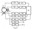
- the part of the circuit which is necessary for controlling the signalscomprises three electronic circuits represented in figure 2 by block 20 and shown in greater detail in figure 3.
- Sensor 2is connected to the signal control system 20 emitting signals X, Y which, on their turn, are fed into an analogical/digital converter 21 having a double channel.
- Said converteris connected to the logical unit 22 containing a memory communicating with the logical unit 22. Answering to the signals emitted by converter 21, the logical unit 22 addresses a memory cell containing correction parameters which are then used to detect the real course angle.
- sensor 2provides for the course angle in parametric form, e.g. signals X and Y are respectively proportional to the sine and cosine functions of the course angle, so that it is possible to obtain the aforesaid angle in a known way by means of a circuit, already known, providing for the course angle in analogical form.
- signals X and Yare respectively proportional to the sine and cosine functions of the course angle, so that it is possible to obtain the aforesaid angle in a known way by means of a circuit, already known, providing for the course angle in analogical form.
- the logical unit 22determines the real course angle as an answer to the signals emitted by converter 21.
- the real course angleis sent from logical unit 22 to display means, already known, and/or to an automatic pilot.
- Figure 3shows in more detail the circuit forming the signal control system 20.
- the exciting winding 3' surrounding the toroidal coreis connected to a parametrical oscillator 23 which, on its turn, is connected to an oscillator 24 and to a vectorial cross-correlator 25.
- the winding 5 of the first couple of windingsis composed by a detecting winding and a feedback winding.
- the detecting windingis connected to a synthetic inductor 26 and to a pre-amplifier 27 feeding signal X into the cross-correlator 25.
- the other winding 4is composed by a detecting winding and a feedback winding.
- the detecting windingis connected to a synthetic inductor 28 and to a pre-amplifier 29 transmitting signal Y to the cross-correlator 25.
- Feedback signals X and Y produced by cross-correlator 25are transmitted to respective integrators (31, 33) and to transconductance amplifiers (30, 32) where they are further sent to the respective feedback windings.
- a current runswhich generates, in the volume occupied by the toroidal core, a magnetic field having the same intensity but the opposite direction as the measured one, so that it constantly keeps the core in a null field, aside from the variations of the external field due to the course changes of the vehicle and to the variations of the local field. This aims to obtain the highest working linearity of the compass.
- the transconductance amplifiers (30, 32)transmit signals X, Y also to respective second-order Bessel filters (34, 35) emitting signals X, Y which are fed into the two-channel, analogical/digital converter 21.
- the compasscan also advantageously comprise a satellite auto-locating unit, for instance of the GPS type, from which it acquires further data which are used, together with the correction parameters obtained from the memory, to settle the real course angle. Without leaving the scope of the invention, it is also possible to omit the satellite auto-locating unit.
- Auxiliary equipmentssuch as the satellite auto-locating unit, the display means, the automatic pilot, etc. which are generally used on boats or in some kinds of vehicles "communicate” by means of a protocol known as "NMEA".
- NMEAa protocol known as "NMEA"
- the signals from converter 21are converted into signals consistent with the "NMEA” protocol by means of a transcoder (not shown).
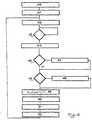
- Block 40represents the initialisation step of the logical unit 22 and block 41 represents the initialisation step of the analogical/digital converter 21. Afterwards the timer (block 42) is started and the time is set to zero (block 43). In the following step, represented by block 44, signals X, Y are read by the sensor. If the Y value is equal to zero (block 45) it is set to 0.000001 (block 47), whereas if the X and Y values exceed 2500 (block 46) they are treated by a Wiener filter (block 48). Block 49 calculates the direction on the basis of received X and Y values and then block 50 carries out the conversion radians to degrees convertion. These final values of the direction are formatted in order to fit them to the NMEA protocol (block 51) and finally they are formatted to fit them to the used display (block 52).
- the logical unit 22acquires further data from said unit.
- the logical unit 22determines the real course angle and sends it to the display means and/or to the automatic pilot, if they are provided, before coming back to step 42 to acquire once again the signals emitted by sensor 2 and repeating the same cycle.
- the memoryis omitted, also the corresponding steps of recalling and acquisition are omitted and, if the satellite auto-locating unit is omitted, also the corresponding step of acquisition is omitted. If both memory and satellite auto-locating unit are omitted, also the corresponding processing step is omitted.
- the compass thus obtainedhad the following features: great lightness, compactness, accuracy and inexpensiveness.
- the compasscan also comprise two or more sensors.
Landscapes
- Physics & Mathematics (AREA)
- General Physics & Mathematics (AREA)
- Engineering & Computer Science (AREA)
- Remote Sensing (AREA)
- Radar, Positioning & Navigation (AREA)
- Electromagnetism (AREA)
- General Life Sciences & Earth Sciences (AREA)
- Environmental & Geological Engineering (AREA)
- Geology (AREA)
- Life Sciences & Earth Sciences (AREA)
- Condensed Matter Physics & Semiconductors (AREA)
- Measuring Magnetic Variables (AREA)
- Organic Low-Molecular-Weight Compounds And Preparation Thereof (AREA)
- Liquid Crystal Substances (AREA)
- Navigation (AREA)
Abstract
Description
Claims (16)
- Electronic compass comprising electronic control means (20, 21, 22), at least onesaturable core sensor (2) having a core (3) supporting and being surrounded by an exciting electric winding (3') forming a coil of amorphousferromagnetic material,wherein the core sensor (2) comprises a first gap, provided betweenthe exciting electric winding (3') and a first pair of windings (4, 5), wherein saidfirst pair of windings (4, 5), surrounding and being supported by first rigidmeans (6), have reciprocally orthogonal turns, whereinthe core (3) is made of an aluminium ring, the first gap is filled by said first rigidmeans (6) and the core sensor (2) comprises a second gap filled by second rigidmeans (7) and provided between said first pair of windings (4, 5) and a secondpair of windings (8, 9), wherein the second pair of windings (8, 9) surrounds and issupported by said second rigid means (7) and have reciprocally orthogonal turnsof reciprocally orthogonal windings (8, 9).
- Electronic compass according to claim 1, wherein said filling rigid means (6, 7)are made of a low thermal expansion coefficient material, preferably epoxyfibreglass reinforced plastic.
- Electronic compass according to claim 1 or 2, two comprisingsensors (2).
- Electronic compass according to claim 1 , wherein said electronic control means(20, 21, 22) comprise means for determining the real course angle of the vehicle,thus counterbalancing the errors produced by magnetic deviation.
- Electronic compass according to claim 4, wherein said electronic control means(20, 21, 22) comprise means apt to display the data detected by the compass.
- Electronic compass according to claim 5, wherein said electronic control means(20, 21, 22) comprise at least an analog/digital converter (21) and a logical unit(22).
- Electronic compass according to claim 6, wherein said electronic control means(20, 21, 22) also comprise a memory communicating with the logical unit (22) and a satellite auto-locating unit and the logical unit (22) acquires further data fromsaid memory and from said satellite auto-locating unit.
- Electronic compass according to claim 7, wherein the logical unit (22) isadapted for carrying out at least the following steps:a) acquire the signals emitted by the aforesaid at least one sensor (2),b) settle a course angle andc) acquire again the signals emitted by said at least one sensor (2), repeating theaforesaid cycle.
- Electronic compass according to claim 8, wherein, by determining the courseangle, the logical unit (22) is adapted for carrying out at least the further followingsteps:a) address the memory through said course angle and acquire from the memorythe correction parameters stored in the memory cell addressed through saidcourse angle;b) obtain the real course angle;c) acquire again the signals emitted by said at least one sensor (2), repeating theaforesaid cycle.
- Electronic compass according to claim 1, whereina signal having proportional amplitude and oppositedirection in relation to the signal emitted by the corresponding winding of the firstpair of windings (4, 5) runs through each winding of the second pair of windings (8, 9).
- Electronic compass according to claim 1, wherein apulse current periodically saturating the core with a frequency of 9.6 kHz, aduration of 5 microseconds and an intensity of 100 A/m runs through said winding (3').
- Electronic compass according to claim 1, wherein the core sensor (2) isconnected to a vehicle by suspension means comprising a pair of suspensionoscillating axes (14, 15) placed on overlapping planes to form a compositependulum having two different oscillating frequencies.
- Compass according to claim 12, wherein the axis of the core sensor (2) isturned of 45° in relation to said suspension oscillating axes (14, 15).
- Electronic compass according to claim 12, wherein the suspension means areadapted to counterbalance inclination angles up to ± 75°.
- Electronic compass according to claim 12, wherein said suspension meanscomprise the pair of suspension axes (14, 15) made of a non-magnetic material,four ball bearings (12, 13) made of a non-magnetic alloy, a central supportingelement (11) of the axis and two supporting elements (16, 17) made of non-magneticmaterial sustaining said ball bearings (12,13).
- Electronic compass according to claim 16, wherein the suspension axis (14,15) are made of a copper-tin alloy and the ball bearings (12,13) are made of acopper-beryllium alloy.
Applications Claiming Priority (3)
| Application Number | Priority Date | Filing Date | Title |
|---|---|---|---|
| IT2000CA000011AITCA20000011A1 (en) | 2000-05-03 | 2000-05-03 | ELECTRONIC COMPASS. |
| ITCA000011 | 2000-05-03 | ||
| PCT/EP2001/004970WO2001084079A1 (en) | 2000-05-03 | 2001-05-03 | Electronic compass |
Publications (2)
| Publication Number | Publication Date |
|---|---|
| EP1281043A1 EP1281043A1 (en) | 2003-02-05 |
| EP1281043B1true EP1281043B1 (en) | 2005-10-05 |
Family
ID=11440962
Family Applications (1)
| Application Number | Title | Priority Date | Filing Date |
|---|---|---|---|
| EP01933921AExpired - LifetimeEP1281043B1 (en) | 2000-05-03 | 2001-05-03 | Electronic compass |
Country Status (10)
| Country | Link |
|---|---|
| US (1) | US6853918B2 (en) |
| EP (1) | EP1281043B1 (en) |
| AT (1) | ATE306070T1 (en) |
| AU (2) | AU6027501A (en) |
| DE (1) | DE60113828T2 (en) |
| DK (1) | DK1281043T3 (en) |
| ES (1) | ES2250404T3 (en) |
| IT (1) | ITCA20000011A1 (en) |
| NZ (1) | NZ522917A (en) |
| WO (1) | WO2001084079A1 (en) |
Families Citing this family (2)
| Publication number | Priority date | Publication date | Assignee | Title |
|---|---|---|---|---|
| JP4365262B2 (en)* | 2004-04-23 | 2009-11-18 | 朝日電装株式会社 | Tilt sensor for boarding means |
| KR101204970B1 (en)* | 2012-06-12 | 2012-11-26 | 한국지질자원연구원 | clinometer, strike and dip angle method in using same |
Family Cites Families (7)
| Publication number | Priority date | Publication date | Assignee | Title |
|---|---|---|---|---|
| US3895869A (en)* | 1974-06-17 | 1975-07-22 | Boeing Co | Heading sensor with compensation windings |
| US4157619A (en)* | 1977-10-14 | 1979-06-12 | Scientific Drilling Controls | Inclination and direction responsive apparatus |
| GB2044460B (en) | 1979-01-11 | 1983-05-25 | Ca Minister Nat Defence | Fluxgate magnetometers |
| US4262427A (en)* | 1979-08-10 | 1981-04-21 | Sperry Corporation | Flux valve compass system |
| US4424631A (en) | 1982-03-02 | 1984-01-10 | Prince Corporation | Electrical compass |
| US5339246A (en) | 1992-03-17 | 1994-08-16 | Zexel Corporation Diahatsu-Nissan | Apparatus for correcting vehicular compass heading with the aid of the global positioning system |
| JPH07324935A (en)* | 1994-05-31 | 1995-12-12 | Sony Corp | Terrestrial-magnetism direction sensor and its manufacture |
- 2000
- 2000-05-03ITIT2000CA000011Apatent/ITCA20000011A1/enunknown
- 2001
- 2001-05-03AUAU6027501Apatent/AU6027501A/enactivePending
- 2001-05-03USUS10/275,393patent/US6853918B2/ennot_activeExpired - Fee Related
- 2001-05-03AUAU2001260275Apatent/AU2001260275B2/ennot_activeCeased
- 2001-05-03ATAT01933921Tpatent/ATE306070T1/ennot_activeIP Right Cessation
- 2001-05-03ESES01933921Tpatent/ES2250404T3/ennot_activeExpired - Lifetime
- 2001-05-03DKDK01933921Tpatent/DK1281043T3/enactive
- 2001-05-03NZNZ522917Apatent/NZ522917A/ennot_activeIP Right Cessation
- 2001-05-03DEDE60113828Tpatent/DE60113828T2/ennot_activeExpired - Lifetime
- 2001-05-03WOPCT/EP2001/004970patent/WO2001084079A1/enactiveIP Right Grant
- 2001-05-03EPEP01933921Apatent/EP1281043B1/ennot_activeExpired - Lifetime
Also Published As
| Publication number | Publication date |
|---|---|
| ITCA20000011A0 (en) | 2000-05-03 |
| AU2001260275B2 (en) | 2005-02-17 |
| EP1281043A1 (en) | 2003-02-05 |
| ITCA20000011A1 (en) | 2001-11-05 |
| ATE306070T1 (en) | 2005-10-15 |
| US20030167122A1 (en) | 2003-09-04 |
| NZ522917A (en) | 2004-02-27 |
| DK1281043T3 (en) | 2006-02-13 |
| AU6027501A (en) | 2001-11-12 |
| DE60113828T2 (en) | 2006-07-13 |
| WO2001084079A1 (en) | 2001-11-08 |
| DE60113828D1 (en) | 2006-02-16 |
| US6853918B2 (en) | 2005-02-08 |
| ES2250404T3 (en) | 2006-04-16 |
Similar Documents
| Publication | Publication Date | Title |
|---|---|---|
| US4546550A (en) | Compass | |
| US6282803B1 (en) | Self calibration circuit for determining an accurate zero compensation for a fluxgate compass | |
| US3991361A (en) | Semi-automatic compass calibrator apparatus for a vehicle mounted flux gate compass system to cancel out effect of local magnetic disturbances | |
| US4424631A (en) | Electrical compass | |
| JPH0518770A (en) | Azimuth detecting device | |
| US20010029430A1 (en) | Positional information display system | |
| EP1876417A1 (en) | Inclination sensor and direction finding device using the same | |
| US3936949A (en) | Static non-swinging course determining device on a vehicle | |
| US2555209A (en) | Method and apparatus for measuring the values of magnetic fields | |
| US4033045A (en) | Portable surveying gyrocompass apparatus | |
| US3628254A (en) | Nonpendulous flux valve compass system | |
| EP1281043B1 (en) | Electronic compass | |
| US2542018A (en) | Compass | |
| JPS6345043B2 (en) | ||
| AU2001260275A1 (en) | Electronic compass | |
| US2376883A (en) | Dynamic earth inductor compass | |
| GB2130729A (en) | Electronic compasses | |
| JPH0666920A (en) | Three-dimensional position measuring device and method | |
| KR100681420B1 (en) | Fluxgate Geomagnetic Sensor Driving Circuit | |
| KR19980028621A (en) | Automatic calibration method of geomagnetic sensor of car navigation system | |
| JP3008813B2 (en) | Direction output device | |
| GB586506A (en) | Improvements in gyromagnetic compasses for aircraft and the like | |
| JPH05164560A (en) | Direction sensor | |
| JPS6319515A (en) | Azimuth detector | |
| SU595494A1 (en) | Device for measuring hole deflection |
Legal Events
| Date | Code | Title | Description |
|---|---|---|---|
| PUAI | Public reference made under article 153(3) epc to a published international application that has entered the european phase | Free format text:ORIGINAL CODE: 0009012 | |
| 17P | Request for examination filed | Effective date:20021202 | |
| AK | Designated contracting states | Designated state(s):AT BE CH CY DE DK ES FI FR GB GR IE IT LI LU MC NL PT SE TR | |
| AX | Request for extension of the european patent | Extension state:AL LT LV MK RO SI | |
| 17Q | First examination report despatched | Effective date:20041102 | |
| GRAP | Despatch of communication of intention to grant a patent | Free format text:ORIGINAL CODE: EPIDOSNIGR1 | |
| GRAS | Grant fee paid | Free format text:ORIGINAL CODE: EPIDOSNIGR3 | |
| GRAA | (expected) grant | Free format text:ORIGINAL CODE: 0009210 | |
| AK | Designated contracting states | Kind code of ref document:B1 Designated state(s):AT BE CH CY DE DK ES FI FR GB GR IE IT LI LU MC NL PT SE TR | |
| PG25 | Lapsed in a contracting state [announced via postgrant information from national office to epo] | Ref country code:CH Free format text:LAPSE BECAUSE OF FAILURE TO SUBMIT A TRANSLATION OF THE DESCRIPTION OR TO PAY THE FEE WITHIN THE PRESCRIBED TIME-LIMIT Effective date:20051005 Ref country code:LI Free format text:LAPSE BECAUSE OF FAILURE TO SUBMIT A TRANSLATION OF THE DESCRIPTION OR TO PAY THE FEE WITHIN THE PRESCRIBED TIME-LIMIT Effective date:20051005 Ref country code:BE Free format text:LAPSE BECAUSE OF FAILURE TO SUBMIT A TRANSLATION OF THE DESCRIPTION OR TO PAY THE FEE WITHIN THE PRESCRIBED TIME-LIMIT Effective date:20051005 Ref country code:AT Free format text:LAPSE BECAUSE OF FAILURE TO SUBMIT A TRANSLATION OF THE DESCRIPTION OR TO PAY THE FEE WITHIN THE PRESCRIBED TIME-LIMIT Effective date:20051005 | |
| REG | Reference to a national code | Ref country code:GB Ref legal event code:FG4D | |
| REG | Reference to a national code | Ref country code:CH Ref legal event code:EP | |
| REG | Reference to a national code | Ref country code:IE Ref legal event code:FG4D | |
| PG25 | Lapsed in a contracting state [announced via postgrant information from national office to epo] | Ref country code:GR Free format text:LAPSE BECAUSE OF FAILURE TO SUBMIT A TRANSLATION OF THE DESCRIPTION OR TO PAY THE FEE WITHIN THE PRESCRIBED TIME-LIMIT Effective date:20060105 | |
| REG | Reference to a national code | Ref country code:SE Ref legal event code:TRGR | |
| REG | Reference to a national code | Ref country code:DK Ref legal event code:T3 | |
| REF | Corresponds to: | Ref document number:60113828 Country of ref document:DE Date of ref document:20060216 Kind code of ref document:P | |
| REG | Reference to a national code | Ref country code:CH Ref legal event code:PL | |
| REG | Reference to a national code | Ref country code:ES Ref legal event code:FG2A Ref document number:2250404 Country of ref document:ES Kind code of ref document:T3 | |
| PG25 | Lapsed in a contracting state [announced via postgrant information from national office to epo] | Ref country code:IE Free format text:LAPSE BECAUSE OF NON-PAYMENT OF DUE FEES Effective date:20060503 | |
| PG25 | Lapsed in a contracting state [announced via postgrant information from national office to epo] | Ref country code:MC Free format text:LAPSE BECAUSE OF NON-PAYMENT OF DUE FEES Effective date:20060531 | |
| ET | Fr: translation filed | ||
| PLBE | No opposition filed within time limit | Free format text:ORIGINAL CODE: 0009261 | |
| STAA | Information on the status of an ep patent application or granted ep patent | Free format text:STATUS: NO OPPOSITION FILED WITHIN TIME LIMIT | |
| 26N | No opposition filed | Effective date:20060706 | |
| REG | Reference to a national code | Ref country code:IE Ref legal event code:MM4A | |
| PG25 | Lapsed in a contracting state [announced via postgrant information from national office to epo] | Ref country code:TR Free format text:LAPSE BECAUSE OF FAILURE TO SUBMIT A TRANSLATION OF THE DESCRIPTION OR TO PAY THE FEE WITHIN THE PRESCRIBED TIME-LIMIT Effective date:20051005 Ref country code:LU Free format text:LAPSE BECAUSE OF NON-PAYMENT OF DUE FEES Effective date:20060503 | |
| PG25 | Lapsed in a contracting state [announced via postgrant information from national office to epo] | Ref country code:CY Free format text:LAPSE BECAUSE OF FAILURE TO SUBMIT A TRANSLATION OF THE DESCRIPTION OR TO PAY THE FEE WITHIN THE PRESCRIBED TIME-LIMIT Effective date:20051005 | |
| PG25 | Lapsed in a contracting state [announced via postgrant information from national office to epo] | Ref country code:IT Free format text:LAPSE BECAUSE OF NON-PAYMENT OF DUE FEES Effective date:20070503 | |
| PGRI | Patent reinstated in contracting state [announced from national office to epo] | Ref country code:IT Effective date:20110616 | |
| PGFP | Annual fee paid to national office [announced via postgrant information from national office to epo] | Ref country code:NL Payment date:20120423 Year of fee payment:12 Ref country code:DK Payment date:20120418 Year of fee payment:12 Ref country code:DE Payment date:20120419 Year of fee payment:12 | |
| PGFP | Annual fee paid to national office [announced via postgrant information from national office to epo] | Ref country code:FR Payment date:20120516 Year of fee payment:12 Ref country code:FI Payment date:20120418 Year of fee payment:12 Ref country code:GB Payment date:20120418 Year of fee payment:12 Ref country code:SE Payment date:20120418 Year of fee payment:12 | |
| PGFP | Annual fee paid to national office [announced via postgrant information from national office to epo] | Ref country code:IT Payment date:20120504 Year of fee payment:12 | |
| PGFP | Annual fee paid to national office [announced via postgrant information from national office to epo] | Ref country code:ES Payment date:20120420 Year of fee payment:12 | |
| PGFP | Annual fee paid to national office [announced via postgrant information from national office to epo] | Ref country code:PT Payment date:20120502 Year of fee payment:12 | |
| REG | Reference to a national code | Ref country code:PT Ref legal event code:MM4A Free format text:LAPSE DUE TO NON-PAYMENT OF FEES Effective date:20131104 | |
| REG | Reference to a national code | Ref country code:NL Ref legal event code:V1 Effective date:20131201 | |
| REG | Reference to a national code | Ref country code:SE Ref legal event code:EUG | |
| GBPC | Gb: european patent ceased through non-payment of renewal fee | Effective date:20130503 | |
| PG25 | Lapsed in a contracting state [announced via postgrant information from national office to epo] | Ref country code:SE Free format text:LAPSE BECAUSE OF NON-PAYMENT OF DUE FEES Effective date:20130504 Ref country code:PT Free format text:LAPSE BECAUSE OF NON-PAYMENT OF DUE FEES Effective date:20131104 Ref country code:DE Free format text:LAPSE BECAUSE OF NON-PAYMENT OF DUE FEES Effective date:20131203 | |
| REG | Reference to a national code | Ref country code:DK Ref legal event code:EBP Effective date:20130531 | |
| REG | Reference to a national code | Ref country code:DE Ref legal event code:R119 Ref document number:60113828 Country of ref document:DE Effective date:20131203 | |
| PG25 | Lapsed in a contracting state [announced via postgrant information from national office to epo] | Ref country code:NL Free format text:LAPSE BECAUSE OF NON-PAYMENT OF DUE FEES Effective date:20131201 Ref country code:IT Free format text:LAPSE BECAUSE OF NON-PAYMENT OF DUE FEES Effective date:20130503 Ref country code:FI Free format text:LAPSE BECAUSE OF NON-PAYMENT OF DUE FEES Effective date:20130503 | |
| REG | Reference to a national code | Ref country code:FR Ref legal event code:ST Effective date:20140131 | |
| PG25 | Lapsed in a contracting state [announced via postgrant information from national office to epo] | Ref country code:DK Free format text:LAPSE BECAUSE OF NON-PAYMENT OF DUE FEES Effective date:20130531 Ref country code:GB Free format text:LAPSE BECAUSE OF NON-PAYMENT OF DUE FEES Effective date:20130503 | |
| PG25 | Lapsed in a contracting state [announced via postgrant information from national office to epo] | Ref country code:FR Free format text:LAPSE BECAUSE OF NON-PAYMENT OF DUE FEES Effective date:20130531 | |
| REG | Reference to a national code | Ref country code:ES Ref legal event code:FD2A Effective date:20140606 | |
| PG25 | Lapsed in a contracting state [announced via postgrant information from national office to epo] | Ref country code:ES Free format text:LAPSE BECAUSE OF NON-PAYMENT OF DUE FEES Effective date:20130504 |