EP1280669B1 - Self-inking stamp - Google Patents
Self-inking stampDownload PDFInfo
- Publication number
- EP1280669B1 EP1280669B1EP01921016AEP01921016AEP1280669B1EP 1280669 B1EP1280669 B1EP 1280669B1EP 01921016 AEP01921016 AEP 01921016AEP 01921016 AEP01921016 AEP 01921016AEP 1280669 B1EP1280669 B1EP 1280669B1
- Authority
- EP
- European Patent Office
- Prior art keywords
- lower component
- bottom part
- stamp
- component
- inking
- Prior art date
- Legal status (The legal status is an assumption and is not a legal conclusion. Google has not performed a legal analysis and makes no representation as to the accuracy of the status listed.)
- Expired - Lifetime
Links
- 239000012780transparent materialSubstances0.000claimsabstractdescription3
- 238000003780insertionMethods0.000description3
- 230000037431insertionEffects0.000description3
- 230000006835compressionEffects0.000description2
- 238000007906compressionMethods0.000description2
- 238000010276constructionMethods0.000description2
- 238000011109contaminationMethods0.000description1
- 238000006073displacement reactionMethods0.000description1
- 238000000605extractionMethods0.000description1
- 238000000034methodMethods0.000description1
Images

Classifications
- B—PERFORMING OPERATIONS; TRANSPORTING
- B41—PRINTING; LINING MACHINES; TYPEWRITERS; STAMPS
- B41K—STAMPS; STAMPING OR NUMBERING APPARATUS OR DEVICES
- B41K1/00—Portable hand-operated devices without means for supporting or locating the articles to be stamped, i.e. hand stamps; Inking devices or other accessories therefor
- B41K1/36—Details
- B41K1/38—Inking devices; Stamping surfaces
- B41K1/40—Inking devices operated by stamping movement
Definitions
- the inventionrelates to a self-inking stamp with Oberschlagfärbung, with a placed on the surface to be stamped base, with a turning mechanism for a arranged in the lower part, between a color pad and a Aufsetzrahmen reciprocally movable back and forth pressure plate carrier, and with a against the force of a spring relative to the lower part displaceable actuating upper part, which surrounds the lower part and is connected via its side parts by a guided in elongated holes of the lower part of the turning axis of the pressure plate carrier with the lower part.
- the actuating upper partis formed substantially hood-like and has both front and rear a recess, which allows access to the ink pad, which is inserted interchangeably into a horizontal shaft of the punch base.
- the inventionaims to simplify both the insertion of the ink pad by a novel design of actuating upper part and lower part, in particular in the case of a kiss exchange, while avoiding any risk of contamination, as well as to improve the handling of the stamp during the stamping process.
- the actuating upper parthas a substantially U-shaped body part and a hood part of transparent material pivotally connected thereto, which has a sloping text receiving surface on the upper crosspiece of the body part and the open front of the body part covered, and that the lower part of the ink pad receptacle on its front side down to open, this opening is covered by a transparent wall part, which of the with the lower part by a resilient locking connection connectable Aufsetzrahmen protrudes upwards.
- the pivot hoodis hinged to the rear side of the upper part of this pivotally and extends from the articulation point on the vertex of the upper part to the front.
- the releasable latching connection of the Aufsetzrahmens with the lower partallows before the first attachment of the same in a simple manner, the assembly of the punch plate carrier by inserting the same into the guide slots of the lower part.
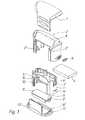
- FIG. 1shows an exploded view of the entire punch according to the invention
- FIG. 2shows a 3 shows a cross section through the punch when the hood is open
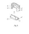
- FIG. 4shows in an exploded view the insertion of the attachment frame.
- the stamp base 1receives a color pad 4, which is inserted into a horizontal shaft 5 of the lower part in the direction of arrow F.
- the upper part 2has a substantially U-shaped body part 2 ', which carries at its upper transverse web an oblique text receiving surface 6, which allows a view from above and from the front, and covered on its upper side and on its front by a transparent pivotable hood part 7 is, which is pivotally mounted at the rear of the upper part 2 at 7 '.
- a transparent pivotable hood part 7By pivoting the hood part 7 of the ink bag tray 5 of the lower part 1 is accessible to replace the ink pad 4, as shown in FIG. 3.
- the upper part 2also receives an actuating compression spring D projecting upwards from the ink pad shaft 5 (compare FIGS. 2 and 3).
- the lower part 1has in its side walls a conventional turning mechanism 10 for a punch plate carrier 11, which is inserted into wall slots 12 of the lower part 1 from below and connected via its stub axle 11 'with elastic lateral retaining tabs 2 "of the upper part 2 by snapping.
- the lower side of the lower part 1is closed by an insert frame 13 which is resiliently snap-fit into the side slots 14 'of the lower part by means of hooks 14, which also forms a transparent cover 13' projecting upwardly from the attachment frame for the open front side of the lower part 1
- Forming the lower part 1facilitates the assembly of the punch because the punch plate carrier 11 can be easily inserted and the attachment frame 13 can be attached
- the upper part 2 and the lower part 1 of the punchcan be held in compression by lateral locking members 3 ', 3 " become.
- An advantage of the construction according to the inventionis that the lower part 1 has the function of a positioning member, because due to the transparent front view of the area to be stamped is made possible, so that the stamp can be placed accurately.
Landscapes
- Printing Methods (AREA)
- Manufacture Or Reproduction Of Printing Formes (AREA)
- Inks, Pencil-Leads, Or Crayons (AREA)
- Purses, Travelling Bags, Baskets, Or Suitcases (AREA)
- Ink Jet Recording Methods And Recording Media Thereof (AREA)
- Ink Jet (AREA)
- Moulds For Moulding Plastics Or The Like (AREA)
Abstract
Description
Translated fromGermanDie Erfindung betrifft einen Selbstfärbestempel mit Oberschlagfärbung, mit einem auf die zu stempelnde Fläche aufsetzbaren Unterteil, mit einem Wendemechanismus für einen im Unterteil angeordneten, zwischen einem Farbkissen und einem Aufsetzrahmen unter gleichzeitiger Wendung hin- und herbewegbaren Druckplattenträger, und mit einem gegen die Kraft einer Feder relativ zum Unterteil verschiebbaren Betätigungs-Oberteil, der den Unterteil umgibt und über seine Seitenteile durch eine in Langlöchern des Unterteiles geführte Wendeachse des Druckplattenträgers mit dem Unterteil verbunden ist.The invention relates to a self-inking stamp with Oberschlagfärbung, with a placed on the surface to be stamped base, with a turning mechanism for a arranged in the lower part, between a color pad and a Aufsetzrahmen reciprocally movable back and forth pressure plate carrier, and with a against the force of a spring relative to the lower part displaceable actuating upper part, which surrounds the lower part and is connected via its side parts by a guided in elongated holes of the lower part of the turning axis of the pressure plate carrier with the lower part.
Derartige Selbstfärbestempel sind bekannt, z.B. aus dem EP 0 459 969 A1. Bei diesen Stempeln ist der Betätigungs-Oberteil im wesentlichen haubenartig ausgebildet und weist sowohl vorne als auch hinten eine Ausnehmung auf, welche den Zutritt zum Farbkissen gestattet, das in einen horizontalen Schacht des Stempelunterteiles austauschbar eingeschoben wird.Such self-inking stamps are known, e.g. from EP 0 459 969 A1. In these punches, the actuating upper part is formed substantially hood-like and has both front and rear a recess, which allows access to the ink pad, which is inserted interchangeably into a horizontal shaft of the punch base.
Die Erfindung zielt darauf ab, durch eine neuartige Gestaltung von Betätigungs-Oberteil und Unterteil sowohl das Einsetzen des Farbkissens zu vereinfachen, insbesondere im Falle eines Kissentausches, und dabei jede Verschmutzungsgefahr zu vermeiden, als auch die Handhabung des Stempels beim Stempelvorgang insgesamt zu verbessern. Dies wird bei einem Stempel der einleitend angegebenen Art erfindungsgemäß dadurch erreicht, daß der Betätigungs-Oberteil einen im wesentlichen U-förmigen Körperteil und einen mit diesem schwenkbar verbundenen Haubenteil aus transparentem Material aufweist, welcher eine schräge Textaufnahmefläche am oberen Quersteg des Körperteiles und die offene Vorderseite des Körperteiles überdeckt, und daß der Unterteil von der Farbkissenaufnahme weg an seiner Vorderseite nach unten zu offen ist, wobei diese Öffnung von einem transparenten Wandteil abgedeckt ist, welcher von dem mit dem Unterteil durch eine federnde Rastverbindung verbindbaren Aufsetzrahmen nach oben ragt.The invention aims to simplify both the insertion of the ink pad by a novel design of actuating upper part and lower part, in particular in the case of a kiss exchange, while avoiding any risk of contamination, as well as to improve the handling of the stamp during the stamping process. This is achieved according to the invention in a stamp of the type specified by the fact that the actuating upper part has a substantially U-shaped body part and a hood part of transparent material pivotally connected thereto, which has a sloping text receiving surface on the upper crosspiece of the body part and the open front of the body part covered, and that the lower part of the ink pad receptacle on its front side down to open, this opening is covered by a transparent wall part, which of the with the lower part by a resilient locking connection connectable Aufsetzrahmen protrudes upwards.
Durch diese Konstruktion wird ein einfacher Tausch der Farbkissen durch horizontales Einschieben bzw. Herausziehen in den bzw. aus dem Aufnahmeschacht des Unterteiles erreicht, weil dazu nur die das Farbkissen an der Vorderseite abdeckende und gegen unbeabsichtigte Verschiebung schützende transparente Haube hochgeklappt werden muß. Zugleich wird eine verbesserte Stempelbetätigung wegen der vergrößerten Grifffläche am Oberteil und infolge der im wesentlichen durchgehenden transparenten Vorderseite des Stempels erreicht, welche die Positionierung des Stempels erleichtert.By this construction, a simple exchange of the ink pad by horizontal insertion or extraction in or out of the receiving shaft of the lower part is achieved because only the color pad on the front covering and protecting against unintentional displacement transparent hood must be folded up. At the same time an improved punch operation is achieved because of the enlarged grip surface on the top and due to the substantially continuous transparent front of the stamp, which facilitates the positioning of the punch.
Gemäß einer bevorzugten Ausführungsform der Erfindung ist die Schwenkhaube im Bereich der Hinterseite des Oberteiles an diesem schwenkbar angelenkt und erstreckt sich von der Anlenkstelle über den Scheitel des Oberteiles zu dessen Vorderseite.According to a preferred embodiment of the invention, the pivot hood is hinged to the rear side of the upper part of this pivotally and extends from the articulation point on the vertex of the upper part to the front.
Die lösbare Rastverbindung des Aufsetzrahmens mit dem Unterteil ermöglicht vor dem erstmaligen Anbringen desselben auf einfache Weise die Montage des Stempelplattenträgers durch Einschieben desselben in die Führungsschlitze des Unterteiles.The releasable latching connection of the Aufsetzrahmens with the lower part allows before the first attachment of the same in a simple manner, the assembly of the punch plate carrier by inserting the same into the guide slots of the lower part.
Die Erfindung wird nachfolgend an einem Ausführungsbeispiel näher erläutert. Es zeigen: Fig. 1 eine gesprengte Darstellung des gesamten erfindungsgemäßen Stempels, Fig. 2 einen Querschnitt durch den geschlossenen Stempel, Fig. 3 einen Querschnitt durch den Stempel bei geöffneter Haube, und Fig. 4 in einer gesprengten Darstellung das Einsetzen des Aufsetzrahmens.The invention will be explained in more detail using an exemplary embodiment. 1 shows an exploded view of the entire punch according to the invention, FIG. 2 shows a 3 shows a cross section through the punch when the hood is open, and FIG. 4 shows in an exploded view the insertion of the attachment frame.
Der in Fig. 1 in gesprengter Darstellung wiedergegebene Selbstfärbestempel weist einen Stempelunterteil 1 und einen diesen umgreifenden, relativ zum Unterteil 1 entgegen der Kraft einer Feder bewegbaren, im wesentlichen U-förmigen Betätigungs-Oberteil 2 auf, der mit dem Unterteil 1 verbunden ist.The reproduced in exploded view in Fig. 1 Selbstfärbestempel has a stamp base 1 and this encompassing, relative to the lower part 1 against the force of a spring movable, substantially U-shaped actuating
Der Stempelunterteil 1 nimmt ein Farbkissen 4 auf, welches in einen horizontalen Schacht 5 des Unterteiles in Pfeilrichtung F eingeschoben wird.The stamp base 1 receives a
Der Oberteil 2 hat einen im wesentlichen U-förmigen Körperteil 2', der an seinem oberen Quersteg eine schräge Textaufnahmefläche 6 trägt, die eine Sicht von oben und von vorne ermöglicht, und an seiner Oberseite und an seiner Vorderseite von einem transparenten schwenkbaren Haubenteil 7 überdeckt ist, der an der Hinterseite des Oberteiles 2 bei 7' schwenkbar gelagert ist. Durch Aufschwenken des Haubenteiles 7 ist der Farbkissenschacht 5 des Unterteiles 1 zum Austausch des Farbkissens 4 zugänglich, wie dies Fig. 3 zeigt. Der Oberteil 2 nimmt auch eine vom Farbkissenschacht 5 nach oben ragende Betätigungs-Druckfeder D auf (vgl. Fig. 2 und 3). Der Unterteil 1 weist in seinen Seitenwänden einen üblichen Wendemechanismus 10 für einen Stempelplattenträger 11 auf, der in Wandschlitze 12 des Unterteiles 1 von unten eingeführt und über seine Achsstummel 11' mit elastischen seitlichen Haltelaschen 2" des Oberteiles 2 durch Einrasten verbunden wird.The
Die Unterseite des Unterteiles 1 wird durch einen in seitliche Schlitze 14' des Unterteiles mittels Haken 14" federnd einschnappbaren Aufsetzrahmen 13 mit Rutschsicherung verschlossen, der auch eine vom Aufsetzrahmen nach oben ragende transparente Abdeckung 13' für die offene Vorderseite des Unterteiles 1 bildet. Durch diese Ausbildung des Unterteiles 1 wird der Zusammenbau des Stempels erleichtert, weil der Stempelplattenträger 11 auf einfache Weise eingesetzt und der Aufsetzrahmen 13 sodann angebracht werden kann. Der Oberteil 2 und der Unterteil 1 des Stempels können durch seitliche Arretierorgane 3', 3" im zusammengedrückten Zustand gehalten werden.The lower side of the lower part 1 is closed by an
Ein Vorteil der erfindungsgemäßen Konstruktion besteht darin, daß der Unterteil 1 die Funktion eines Positionierungsorganes hat, weil infolge der transparenten Vorderseite die Sicht auf den zu bestempelnden Bereich ermöglicht wird, so daß der Stempel genau aufgesetzt werden kann.An advantage of the construction according to the invention is that the lower part 1 has the function of a positioning member, because due to the transparent front view of the area to be stamped is made possible, so that the stamp can be placed accurately.
Claims (2)
- Self-inking stamp with overhead inking, comprising a bottom part (1) which can be positioned on the surface to be stamped, a swivel mechanism (10) for a print platen support (11) disposed in the bottom part which can be moved backwards and forwards between a stamp pad (4) and a support frame whilst simultaneously swivelling, and an actuator top part (2) surrounding the bottom part which can be displaced against the bias of a spring relative to the bottom part and which is connected to the bottom part at its side parts by means of a swivel pin (11') guided in slots (12) of the bottom part,characterised in that the actuator top part (2) comprises an essentially U-shaped body part (2') and a hood part (7) made from transparent material pivotably connected to it, which straddles an oblique text-receiving surface (6) on the top cross-member of the body part (2') and the open front face of the body part, and the bottom part (1) is open in the direction towards the bottom at its front face remote from the ink pad mount (5) and this opening is covered by a transparent wall part (13') which projects upwards from the support frame (13), which can be connected to the bottom part by a resilient catch connection (14', 14").
- Self-inking stamp as claimed in claim 1,characterised in that, in the region of the rear face of the top part (2), the pivoting hood part (7) is pivotably linked to the latter and extends from the linking point across the apex of the top part to its front face.
Applications Claiming Priority (3)
| Application Number | Priority Date | Filing Date | Title |
|---|---|---|---|
| AT7842000 | 2000-05-04 | ||
| AT7842000 | 2000-05-04 | ||
| PCT/AT2001/000115WO2001083227A1 (en) | 2000-05-04 | 2001-04-18 | Self-inking stamp |
Publications (2)
| Publication Number | Publication Date |
|---|---|
| EP1280669A1 EP1280669A1 (en) | 2003-02-05 |
| EP1280669B1true EP1280669B1 (en) | 2007-02-28 |
Family
ID=3680901
Family Applications (1)
| Application Number | Title | Priority Date | Filing Date |
|---|---|---|---|
| EP01921016AExpired - LifetimeEP1280669B1 (en) | 2000-05-04 | 2001-04-18 | Self-inking stamp |
Country Status (8)
| Country | Link |
|---|---|
| US (1) | US6761114B2 (en) |
| EP (1) | EP1280669B1 (en) |
| AT (1) | ATE355181T1 (en) |
| CA (1) | CA2407241C (en) |
| DE (1) | DE50112121D1 (en) |
| ES (1) | ES2282243T3 (en) |
| PT (1) | PT1280669E (en) |
| WO (1) | WO2001083227A1 (en) |
Cited By (5)
| Publication number | Priority date | Publication date | Assignee | Title |
|---|---|---|---|---|
| WO2014113832A1 (en)* | 2013-01-24 | 2014-07-31 | Colop Stempelerzeugung Skopek Gesellschaft M.B.H. & Co. Kg. | Self-inking stamp |
| EP2765006B1 (en) | 2013-01-16 | 2015-06-03 | Sun Same Enterprises Co., Ltd. | Stamp assembly |
| US9227450B2 (en) | 2013-01-24 | 2016-01-05 | Colop Stempelerzeugung Skopek Gesellschaft M.B.H. & Co. Kg. | Self-inking stamp with a stamp housing |
| US9358822B2 (en) | 2013-01-24 | 2016-06-07 | Colop Stempelerzeugung Skopek Gesellschaft M.B.H. & Co. Kg. | Mounting device for a stamp plate |
| US9884502B2 (en) | 2013-01-24 | 2018-02-06 | Colop Stempelerzeugung Skopek Gesellschaft M.B.H. & Co. Kg. | Device for guiding an ink pad container and self-inking stamp |
Families Citing this family (45)
| Publication number | Priority date | Publication date | Assignee | Title |
|---|---|---|---|---|
| AT3176U1 (en)* | 1999-02-18 | 1999-11-25 | Colop Stempelerzeugung Skopek | SELF-COLORING HAND STAMP |
| AT414342B (en)* | 2002-05-27 | 2011-09-15 | Trodat Gmbh | STAMP AND RECORDING DEVICE FOR A STAMPING CUSHION |
| AT411976B (en)* | 2002-05-27 | 2004-08-26 | Trodat Gmbh | STAMP AND RECEIVING DEVICE FOR A STAMP PILLOW |
| AT6731U1 (en)* | 2003-03-18 | 2004-03-25 | Colop Stempelerzeugung Skopek | SELF-STAINING STAMP WITH HIGH-PURPLE COLORING AND COLOR CUSHION CONTAINER HIEFÜR |
| AT412545B (en)* | 2003-04-16 | 2005-04-25 | Design Shopping Gmbh | Self-inking stamp with a top ink pad for stamping two different impressions comprises two structures arranged on top of each other and displaceably mounted in a trigger element |
| AT412544B (en)* | 2003-04-16 | 2005-04-25 | Design Shopping Gmbh | Self-inking stamp with a top ink pad for stamping two different impressions comprises two structures arranged on top of each other and displaceably mounted in a trigger element |
| USD508942S1 (en)* | 2003-11-17 | 2005-08-30 | Colop Stempelerzeugung Skopek Gmbh & Co. Kg | Stamp |
| US7374355B2 (en)* | 2004-01-21 | 2008-05-20 | Silverbrook Research Pty Ltd | Inkjet printer cradle for receiving a pagewidth printhead cartridge |
| US7425050B2 (en)* | 2004-01-21 | 2008-09-16 | Silverbrook Research Pty Ltd | Method for facilitating maintenance of an inkjet printer having a pagewidth printhead |
| US7364263B2 (en)* | 2004-01-21 | 2008-04-29 | Silverbrook Research Pty Ltd | Removable inkjet printer cartridge |
| US7121655B2 (en)* | 2004-01-21 | 2006-10-17 | Silverbrook Research Pty Ltd | Inkjet printer cartridge refill dispenser |
| US7731327B2 (en)* | 2004-01-21 | 2010-06-08 | Silverbrook Research Pty Ltd | Desktop printer with cartridge incorporating printhead integrated circuit |
| US7645025B2 (en)* | 2004-01-21 | 2010-01-12 | Silverbrook Research Pty Ltd | Inkjet printer cartridge with two printhead integrated circuits |
| US7232208B2 (en)* | 2004-01-21 | 2007-06-19 | Silverbrook Research Pty Ltd | Inkjet printer cartridge refill dispenser with plunge action |
| US7469989B2 (en)* | 2004-01-21 | 2008-12-30 | Silverbrook Research Pty Ltd | Printhead chip having longitudinal ink supply channels interrupted by transverse bridges |
| US20050157112A1 (en)* | 2004-01-21 | 2005-07-21 | Silverbrook Research Pty Ltd | Inkjet printer cradle with shaped recess for receiving a printer cartridge |
| US7441865B2 (en) | 2004-01-21 | 2008-10-28 | Silverbrook Research Pty Ltd | Printhead chip having longitudinal ink supply channels |
| US7448734B2 (en)* | 2004-01-21 | 2008-11-11 | Silverbrook Research Pty Ltd | Inkjet printer cartridge with pagewidth printhead |
| US7097291B2 (en) | 2004-01-21 | 2006-08-29 | Silverbrook Research Pty Ltd | Inkjet printer cartridge with ink refill port having multiple ink couplings |
| US7303255B2 (en)* | 2004-01-21 | 2007-12-04 | Silverbrook Research Pty Ltd | Inkjet printer cartridge with a compressed air port |
| AT412960B (en)* | 2004-03-08 | 2005-09-26 | Colop Stempelerzeugung Skopek | Self-inking hand TEMPLE |
| USD516118S1 (en)* | 2004-09-20 | 2006-02-28 | Colop Stempelerzeugung Skopek | Stamp |
| USD518506S1 (en)* | 2004-03-18 | 2006-04-04 | Colop Stempelerzeugung Skopek Gmbh & Co. Kg | Stamp |
| USD518087S1 (en)* | 2004-05-19 | 2006-03-28 | Shiny Shih | Self inking stamp |
| US6945172B1 (en)* | 2004-06-10 | 2005-09-20 | Shiny Shih | Housing assembly for a self-inking stamp |
| AT7861U1 (en)* | 2004-09-14 | 2005-10-17 | Trodat Gmbh | HAND STAMP, AND COVER FOR HAND STAMP |
| USD545885S1 (en)* | 2005-09-09 | 2007-07-03 | Colop Stempelerzeugung Skopek Gmbh & Co. Kg | Printer stamp |
| USD539836S1 (en)* | 2005-03-11 | 2007-04-03 | Colop Stempelerzeugung Skopekgmbh & Co. Kg | Printer stamp |
| BRPI0501693A (en)* | 2005-05-10 | 2007-01-16 | Paulo Eduardo Ferreira D Rocha | pre-inked automatic stamp |
| USD538329S1 (en)* | 2006-01-13 | 2007-03-13 | Megilo Co., Ltd. | Stamp assembly |
| US20070169650A1 (en)* | 2006-01-17 | 2007-07-26 | Shiny Shih | Housing assembly for a self-inking stamp |
| US20080019870A1 (en)* | 2006-07-21 | 2008-01-24 | Michael John Newman | Integrated medical device dispensing and lancing mechanisms and methods of use |
| US20090253981A1 (en)* | 2008-04-03 | 2009-10-08 | Hamilton Brian H | Skin Marking Tool for Radiological Imaging Material |
| USD587746S1 (en) | 2008-06-10 | 2009-03-03 | Fiskars Brands, Inc. | Stamping tool |
| US20090301327A1 (en)* | 2008-06-10 | 2009-12-10 | Fiskars Brands, Inc. | Stamping Tool |
| CN102264870B (en)* | 2008-12-23 | 2014-01-08 | 英特卡设备有限公司 | Substance recovery apparatus and method for regulating substance inventory in one or more units |
| US8387528B2 (en)* | 2009-01-15 | 2013-03-05 | Crayola Llc | Self-sealing stamping device |
| AT507833A3 (en) | 2009-01-30 | 2013-06-15 | Trodat Gmbh | STAMP AND PUNCH CUSHION FOR A SELF-STAINED STAMP |
| TWD144364S (en) | 2010-03-19 | 2012-01-21 | 特羅戴有限公司 | Ink-pad for a self-inking hand stamp |
| TWD142484S1 (en)* | 2010-03-19 | 2011-09-01 | 特羅戴有限公司 | Self-inking hand stamp |
| USD629838S1 (en) | 2010-04-14 | 2010-12-28 | Fiskars Brands, Inc. | Stamp roller |
| AT513900B1 (en)* | 2013-01-24 | 2018-08-15 | Colop Stempelerzeugung Skopek Gmbh & Co Kg | self-inking stamp |
| AT514245B1 (en)* | 2013-04-22 | 2025-03-15 | Colop Stempelerzeugung Skopek Gmbh & Co Kg | Ink pad holder and device and method for producing such a |
| AT520967A1 (en) | 2018-02-15 | 2019-09-15 | Trodat Gmbh | Stamp, in particular date stamp |
| CN112140756B (en)* | 2020-08-18 | 2021-09-10 | 深圳市银之杰科技股份有限公司 | Portable anti-theft seal cartridge |
Family Cites Families (11)
| Publication number | Priority date | Publication date | Assignee | Title |
|---|---|---|---|---|
| US4289070A (en)* | 1979-06-26 | 1981-09-15 | Cosco Industries, Inc. | Rubber stamp |
| US4676162A (en)* | 1985-06-17 | 1987-06-30 | Porelon, Inc. | Rubber stamp |
| US4852489A (en) | 1987-11-18 | 1989-08-01 | M&R Marking Systems, Inc. | Self-inking stamping device |
| IL89972A (en)* | 1989-04-16 | 1991-06-30 | Hamivreshet Brush Factory | Automatic rubber stamp device |
| AT394682B (en) | 1990-05-23 | 1992-05-25 | Just Gmbh Walter | SELF-COLORING STAMP WITH ROLL-ON COLORING |
| GB2304078B (en)* | 1995-08-07 | 1998-09-02 | Mark Universal Ltd | Stamping device |
| PL311908A1 (en)* | 1995-12-18 | 1997-06-23 | Lucjan Poplawski | Stamp holder |
| TW339735U (en)* | 1997-10-20 | 1998-09-01 | Sun Same Entpr Co Ltd | Improvement on an ink-carrying chop |
| US5974969A (en)* | 1998-02-04 | 1999-11-02 | Brother Kogyo Kabushiki Kaisha | Stamp unit with ink pack filled with ink |
| AT3176U1 (en)* | 1999-02-18 | 1999-11-25 | Colop Stempelerzeugung Skopek | SELF-COLORING HAND STAMP |
| US6189450B1 (en)* | 1999-10-15 | 2001-02-20 | Shiny Shih | Ink refillable stamp |
- 2001
- 2001-04-18EPEP01921016Apatent/EP1280669B1/ennot_activeExpired - Lifetime
- 2001-04-18ATAT01921016Tpatent/ATE355181T1/enactive
- 2001-04-18CACA002407241Apatent/CA2407241C/ennot_activeExpired - Fee Related
- 2001-04-18DEDE50112121Tpatent/DE50112121D1/ennot_activeExpired - Fee Related
- 2001-04-18ESES01921016Tpatent/ES2282243T3/ennot_activeExpired - Lifetime
- 2001-04-18WOPCT/AT2001/000115patent/WO2001083227A1/enactiveIP Right Grant
- 2001-04-18USUS10/275,223patent/US6761114B2/ennot_activeExpired - Fee Related
- 2001-04-18PTPT01921016Tpatent/PT1280669E/enunknown
Cited By (7)
| Publication number | Priority date | Publication date | Assignee | Title |
|---|---|---|---|---|
| EP2765006B1 (en) | 2013-01-16 | 2015-06-03 | Sun Same Enterprises Co., Ltd. | Stamp assembly |
| WO2014113832A1 (en)* | 2013-01-24 | 2014-07-31 | Colop Stempelerzeugung Skopek Gesellschaft M.B.H. & Co. Kg. | Self-inking stamp |
| US9221287B2 (en) | 2013-01-24 | 2015-12-29 | Colop Stempelerzeugung Skopek Gesellschaft M.B.H. & Co. Kg. | Self-inking stamp |
| US9227450B2 (en) | 2013-01-24 | 2016-01-05 | Colop Stempelerzeugung Skopek Gesellschaft M.B.H. & Co. Kg. | Self-inking stamp with a stamp housing |
| US9358822B2 (en) | 2013-01-24 | 2016-06-07 | Colop Stempelerzeugung Skopek Gesellschaft M.B.H. & Co. Kg. | Mounting device for a stamp plate |
| RU2636557C2 (en)* | 2013-01-24 | 2017-11-23 | Колоп Штемпельэрцойгунг Скопек Гезельшафт М.Б.Х. Унд Ко. Кг. | Self-stainable stamp |
| US9884502B2 (en) | 2013-01-24 | 2018-02-06 | Colop Stempelerzeugung Skopek Gesellschaft M.B.H. & Co. Kg. | Device for guiding an ink pad container and self-inking stamp |
Also Published As
| Publication number | Publication date |
|---|---|
| CA2407241A1 (en) | 2002-10-31 |
| US20040007144A1 (en) | 2004-01-15 |
| US6761114B2 (en) | 2004-07-13 |
| CA2407241C (en) | 2009-01-20 |
| DE50112121D1 (en) | 2007-04-12 |
| EP1280669A1 (en) | 2003-02-05 |
| WO2001083227A1 (en) | 2001-11-08 |
| ES2282243T3 (en) | 2007-10-16 |
| ATE355181T1 (en) | 2006-03-15 |
| PT1280669E (en) | 2007-06-05 |
Similar Documents
| Publication | Publication Date | Title |
|---|---|---|
| EP1280669B1 (en) | Self-inking stamp | |
| AT411976B (en) | STAMP AND RECEIVING DEVICE FOR A STAMP PILLOW | |
| AT404695B (en) | STAMP DEVICE | |
| EP3498485B1 (en) | Stamp | |
| DE69604597T2 (en) | STAMP HOLDER | |
| AT412772B (en) | Self-inking hand TEMPLE | |
| AT501174B1 (en) | HAND TEMPLE-TYPE UNIT | |
| EP2634005B1 (en) | Manual stamp with coupled lid | |
| EP4419334B1 (en) | Self-inking stamping device and method for opening a cover | |
| EP0325904B1 (en) | Self-inking stamp | |
| AT4935U1 (en) | SELF-COLORING HAND STAMP WITH A SWIVELING TYPE UNIT AND GARNITURE WITH SUCH A SELF-COLORING STAMP | |
| WO2001083226A1 (en) | Self-inking stamp | |
| EP1851061A2 (en) | Stamp comprising a holding device for a stamping pad carrying device | |
| AT505992B1 (en) | POCKET STAMP | |
| AT522302B1 (en) | handstamp | |
| WO2001083228A1 (en) | Self-inking stamp | |
| AT518588B1 (en) | pad holder | |
| DE4114451C1 (en) | ||
| AT526894A1 (en) | Self-inking stamp and method for removing a turning axis from a self-inking stamp | |
| EP0794870B1 (en) | Stamping device | |
| AT7255U1 (en) | STAMP AND RECEIVING DEVICE FOR A STAMP PILLOW | |
| WO2019157546A1 (en) | Stamp, in particular a date stamp | |
| DE4428114A1 (en) | Document file mechanism with guide pins on baseplate | |
| DE1211581B (en) | Stapler |
Legal Events
| Date | Code | Title | Description |
|---|---|---|---|
| PUAI | Public reference made under article 153(3) epc to a published international application that has entered the european phase | Free format text:ORIGINAL CODE: 0009012 | |
| 17P | Request for examination filed | Effective date:20021031 | |
| AK | Designated contracting states | Designated state(s):AT BE CH CY DE DK ES FI FR GB GR IE IT LI LU MC NL PT SE TR | |
| GRAP | Despatch of communication of intention to grant a patent | Free format text:ORIGINAL CODE: EPIDOSNIGR1 | |
| GRAS | Grant fee paid | Free format text:ORIGINAL CODE: EPIDOSNIGR3 | |
| GRAA | (expected) grant | Free format text:ORIGINAL CODE: 0009210 | |
| AK | Designated contracting states | Kind code of ref document:B1 Designated state(s):AT BE CH CY DE DK ES FI FR GB GR IE IT LI LU MC NL PT SE TR | |
| PG25 | Lapsed in a contracting state [announced via postgrant information from national office to epo] | Ref country code:FI Free format text:LAPSE BECAUSE OF FAILURE TO SUBMIT A TRANSLATION OF THE DESCRIPTION OR TO PAY THE FEE WITHIN THE PRESCRIBED TIME-LIMIT Effective date:20070228 Ref country code:DK Free format text:LAPSE BECAUSE OF FAILURE TO SUBMIT A TRANSLATION OF THE DESCRIPTION OR TO PAY THE FEE WITHIN THE PRESCRIBED TIME-LIMIT Effective date:20070228 Ref country code:IE Free format text:LAPSE BECAUSE OF FAILURE TO SUBMIT A TRANSLATION OF THE DESCRIPTION OR TO PAY THE FEE WITHIN THE PRESCRIBED TIME-LIMIT Effective date:20070228 | |
| REG | Reference to a national code | Ref country code:GB Ref legal event code:FG4D Free format text:NOT ENGLISH | |
| REG | Reference to a national code | Ref country code:CH Ref legal event code:EP | |
| REF | Corresponds to: | Ref document number:50112121 Country of ref document:DE Date of ref document:20070412 Kind code of ref document:P | |
| REG | Reference to a national code | Ref country code:IE Ref legal event code:FG4D Free format text:LANGUAGE OF EP DOCUMENT: GERMAN | |
| PG25 | Lapsed in a contracting state [announced via postgrant information from national office to epo] | Ref country code:SE Free format text:LAPSE BECAUSE OF FAILURE TO SUBMIT A TRANSLATION OF THE DESCRIPTION OR TO PAY THE FEE WITHIN THE PRESCRIBED TIME-LIMIT Effective date:20070531 | |
| REG | Reference to a national code | Ref country code:CH Ref legal event code:NV Representative=s name:ABP PATENT NETWORK SWISS GMBH | |
| REG | Reference to a national code | Ref country code:PT Ref legal event code:SC4A Free format text:AVAILABILITY OF NATIONAL TRANSLATION Effective date:20070524 | |
| GBT | Gb: translation of ep patent filed (gb section 77(6)(a)/1977) | Effective date:20070523 | |
| ET | Fr: translation filed | ||
| REG | Reference to a national code | Ref country code:ES Ref legal event code:FG2A Ref document number:2282243 Country of ref document:ES Kind code of ref document:T3 | |
| REG | Reference to a national code | Ref country code:IE Ref legal event code:FD4D | |
| PLBE | No opposition filed within time limit | Free format text:ORIGINAL CODE: 0009261 | |
| STAA | Information on the status of an ep patent application or granted ep patent | Free format text:STATUS: NO OPPOSITION FILED WITHIN TIME LIMIT | |
| 26N | No opposition filed | Effective date:20071129 | |
| PGFP | Annual fee paid to national office [announced via postgrant information from national office to epo] | Ref country code:BE Payment date:20080505 Year of fee payment:8 Ref country code:PT Payment date:20080409 Year of fee payment:8 | |
| REG | Reference to a national code | Ref country code:FR Ref legal event code:ST Effective date:20081231 | |
| PG25 | Lapsed in a contracting state [announced via postgrant information from national office to epo] | Ref country code:MC Free format text:LAPSE BECAUSE OF NON-PAYMENT OF DUE FEES Effective date:20070430 | |
| PG25 | Lapsed in a contracting state [announced via postgrant information from national office to epo] | Ref country code:FR Free format text:LAPSE BECAUSE OF NON-PAYMENT OF DUE FEES Effective date:20080430 | |
| REG | Reference to a national code | Ref country code:FR Ref legal event code:D3 | |
| PG25 | Lapsed in a contracting state [announced via postgrant information from national office to epo] | Ref country code:CY Free format text:LAPSE BECAUSE OF FAILURE TO SUBMIT A TRANSLATION OF THE DESCRIPTION OR TO PAY THE FEE WITHIN THE PRESCRIBED TIME-LIMIT Effective date:20070228 | |
| PGFP | Annual fee paid to national office [announced via postgrant information from national office to epo] | Ref country code:ES Payment date:20090529 Year of fee payment:9 Ref country code:NL Payment date:20090528 Year of fee payment:9 | |
| PG25 | Lapsed in a contracting state [announced via postgrant information from national office to epo] | Ref country code:LU Free format text:LAPSE BECAUSE OF NON-PAYMENT OF DUE FEES Effective date:20070418 | |
| PGFP | Annual fee paid to national office [announced via postgrant information from national office to epo] | Ref country code:DE Payment date:20090529 Year of fee payment:9 Ref country code:FR Payment date:20090528 Year of fee payment:9 Ref country code:IT Payment date:20090126 Year of fee payment:9 | |
| PG25 | Lapsed in a contracting state [announced via postgrant information from national office to epo] | Ref country code:TR Free format text:LAPSE BECAUSE OF FAILURE TO SUBMIT A TRANSLATION OF THE DESCRIPTION OR TO PAY THE FEE WITHIN THE PRESCRIBED TIME-LIMIT Effective date:20070228 | |
| REG | Reference to a national code | Ref country code:PT Ref legal event code:MM4A Free format text:LAPSE DUE TO NON-PAYMENT OF FEES Effective date:20091019 | |
| PGFP | Annual fee paid to national office [announced via postgrant information from national office to epo] | Ref country code:CH Payment date:20090511 Year of fee payment:9 | |
| BERE | Be: lapsed | Owner name:TRODAT GMBH Effective date:20090430 | |
| PGFP | Annual fee paid to national office [announced via postgrant information from national office to epo] | Ref country code:GB Payment date:20090526 Year of fee payment:9 | |
| PG25 | Lapsed in a contracting state [announced via postgrant information from national office to epo] | Ref country code:PT Free format text:LAPSE BECAUSE OF NON-PAYMENT OF DUE FEES Effective date:20091019 | |
| PG25 | Lapsed in a contracting state [announced via postgrant information from national office to epo] | Ref country code:BE Free format text:LAPSE BECAUSE OF NON-PAYMENT OF DUE FEES Effective date:20090430 | |
| REG | Reference to a national code | Ref country code:NL Ref legal event code:V1 Effective date:20101101 | |
| REG | Reference to a national code | Ref country code:CH Ref legal event code:PL | |
| GBPC | Gb: european patent ceased through non-payment of renewal fee | Effective date:20100418 | |
| REG | Reference to a national code | Ref country code:FR Ref legal event code:ST Effective date:20101230 | |
| PG25 | Lapsed in a contracting state [announced via postgrant information from national office to epo] | Ref country code:NL Free format text:LAPSE BECAUSE OF NON-PAYMENT OF DUE FEES Effective date:20101101 | |
| PG25 | Lapsed in a contracting state [announced via postgrant information from national office to epo] | Ref country code:CH Free format text:LAPSE BECAUSE OF NON-PAYMENT OF DUE FEES Effective date:20100430 Ref country code:LI Free format text:LAPSE BECAUSE OF NON-PAYMENT OF DUE FEES Effective date:20100430 Ref country code:DE Free format text:LAPSE BECAUSE OF NON-PAYMENT OF DUE FEES Effective date:20101103 | |
| PG25 | Lapsed in a contracting state [announced via postgrant information from national office to epo] | Ref country code:GB Free format text:LAPSE BECAUSE OF NON-PAYMENT OF DUE FEES Effective date:20100418 Ref country code:IT Free format text:LAPSE BECAUSE OF NON-PAYMENT OF DUE FEES Effective date:20100418 | |
| REG | Reference to a national code | Ref country code:ES Ref legal event code:FD2A Effective date:20110714 | |
| PG25 | Lapsed in a contracting state [announced via postgrant information from national office to epo] | Ref country code:ES Free format text:LAPSE BECAUSE OF NON-PAYMENT OF DUE FEES Effective date:20110704 Ref country code:GR Free format text:LAPSE BECAUSE OF NON-PAYMENT OF DUE FEES Effective date:20070430 | |
| PG25 | Lapsed in a contracting state [announced via postgrant information from national office to epo] | Ref country code:ES Free format text:LAPSE BECAUSE OF NON-PAYMENT OF DUE FEES Effective date:20100419 | |
| PG25 | Lapsed in a contracting state [announced via postgrant information from national office to epo] | Ref country code:FR Free format text:LAPSE BECAUSE OF NON-PAYMENT OF DUE FEES Effective date:20100430 | |
| PG25 | Lapsed in a contracting state [announced via postgrant information from national office to epo] | Ref country code:TR Free format text:LAPSE BECAUSE OF FAILURE TO SUBMIT A TRANSLATION OF THE DESCRIPTION OR TO PAY THE FEE WITHIN THE PRESCRIBED TIME-LIMIT Effective date:20120418 | |
| PGFP | Annual fee paid to national office [announced via postgrant information from national office to epo] | Ref country code:AT Payment date:20120327 Year of fee payment:12 | |
| REG | Reference to a national code | Ref country code:AT Ref legal event code:MM01 Ref document number:355181 Country of ref document:AT Kind code of ref document:T Effective date:20130430 | |
| PG25 | Lapsed in a contracting state [announced via postgrant information from national office to epo] | Ref country code:AT Free format text:LAPSE BECAUSE OF NON-PAYMENT OF DUE FEES Effective date:20130430 | |
| PGFP | Annual fee paid to national office [announced via postgrant information from national office to epo] | Ref country code:TR Payment date:20110329 Year of fee payment:11 | |
| PG25 | Lapsed in a contracting state [announced via postgrant information from national office to epo] | Ref country code:FR Free format text:LAPSE BECAUSE OF NON-PAYMENT OF DUE FEES Effective date:20081231 |