EP1280602B1 - Capillary flow control in a fluidic diagnostic device - Google Patents
Capillary flow control in a fluidic diagnostic deviceDownload PDFInfo
- Publication number
- EP1280602B1 EP1280602B1EP01937160AEP01937160AEP1280602B1EP 1280602 B1EP1280602 B1EP 1280602B1EP 01937160 AEP01937160 AEP 01937160AEP 01937160 AEP01937160 AEP 01937160AEP 1280602 B1EP1280602 B1EP 1280602B1
- Authority
- EP
- European Patent Office
- Prior art keywords
- sample
- measurement area
- channel
- layer
- region
- Prior art date
- Legal status (The legal status is an assumption and is not a legal conclusion. Google has not performed a legal analysis and makes no representation as to the accuracy of the status listed.)
- Expired - Lifetime
Links
- 238000005259measurementMethods0.000claimsdescription39
- 239000012530fluidSubstances0.000claimsdescription18
- 210000004369bloodAnatomy0.000claimsdescription11
- 239000008280bloodSubstances0.000claimsdescription11
- 239000013060biological fluidSubstances0.000claimsdescription10
- PGOHTUIFYSHAQG-LJSDBVFPSA-N(2S)-6-amino-2-[[(2S)-5-amino-2-[[(2S)-2-[[(2S)-2-[[(2S)-2-[[(2S)-4-amino-2-[[(2S)-2-[[(2S)-2-[[(2S)-2-[[(2S)-2-[[(2S)-5-amino-2-[[(2S)-5-amino-2-[[(2S)-2-[[(2S)-2-[[(2S)-2-[[(2S,3R)-2-[[(2S)-5-amino-2-[[(2S)-2-[[(2S)-2-[[(2S,3R)-2-[[(2S)-2-[[(2S)-2-[[(2S)-2-[[(2S)-2-[[(2S)-5-amino-2-[[(2S)-1-[(2S,3R)-2-[[(2S)-2-[[(2S)-2-[[(2R)-2-[[(2S)-2-[[(2S)-2-[[2-[[(2S)-2-[[(2S)-2-[[(2S)-2-[[(2S)-1-[(2S)-2-[[(2S)-2-[[(2S)-2-[[(2S)-2-amino-4-methylsulfanylbutanoyl]amino]-3-(1H-indol-3-yl)propanoyl]amino]-5-carbamimidamidopentanoyl]amino]propanoyl]pyrrolidine-2-carbonyl]amino]-3-methylbutanoyl]amino]-4-methylpentanoyl]amino]-4-methylpentanoyl]amino]acetyl]amino]-3-hydroxypropanoyl]amino]-4-methylpentanoyl]amino]-3-sulfanylpropanoyl]amino]-4-methylsulfanylbutanoyl]amino]-5-carbamimidamidopentanoyl]amino]-3-hydroxybutanoyl]pyrrolidine-2-carbonyl]amino]-5-oxopentanoyl]amino]-3-hydroxypropanoyl]amino]-3-hydroxypropanoyl]amino]-3-(1H-imidazol-5-yl)propanoyl]amino]-4-methylpentanoyl]amino]-3-hydroxybutanoyl]amino]-3-(1H-indol-3-yl)propanoyl]amino]-5-carbamimidamidopentanoyl]amino]-5-oxopentanoyl]amino]-3-hydroxybutanoyl]amino]-3-hydroxypropanoyl]amino]-3-carboxypropanoyl]amino]-3-hydroxypropanoyl]amino]-5-oxopentanoyl]amino]-5-oxopentanoyl]amino]-3-phenylpropanoyl]amino]-5-carbamimidamidopentanoyl]amino]-3-methylbutanoyl]amino]-4-methylpentanoyl]amino]-4-oxobutanoyl]amino]-5-carbamimidamidopentanoyl]amino]-3-(1H-indol-3-yl)propanoyl]amino]-4-carboxybutanoyl]amino]-5-oxopentanoyl]amino]hexanoic acidChemical compoundCSCC[C@H](N)C(=O)N[C@@H](Cc1c[nH]c2ccccc12)C(=O)N[C@@H](CCCNC(N)=N)C(=O)N[C@@H](C)C(=O)N1CCC[C@H]1C(=O)N[C@@H](C(C)C)C(=O)N[C@@H](CC(C)C)C(=O)N[C@@H](CC(C)C)C(=O)NCC(=O)N[C@@H](CO)C(=O)N[C@@H](CC(C)C)C(=O)N[C@@H](CS)C(=O)N[C@@H](CCSC)C(=O)N[C@@H](CCCNC(N)=N)C(=O)N[C@@H]([C@@H](C)O)C(=O)N1CCC[C@H]1C(=O)N[C@@H](CCC(N)=O)C(=O)N[C@@H](CO)C(=O)N[C@@H](CO)C(=O)N[C@@H](Cc1cnc[nH]1)C(=O)N[C@@H](CC(C)C)C(=O)N[C@@H]([C@@H](C)O)C(=O)N[C@@H](Cc1c[nH]c2ccccc12)C(=O)N[C@@H](CCCNC(N)=N)C(=O)N[C@@H](CCC(N)=O)C(=O)N[C@@H]([C@@H](C)O)C(=O)N[C@@H](CO)C(=O)N[C@@H](CC(O)=O)C(=O)N[C@@H](CO)C(=O)N[C@@H](CCC(N)=O)C(=O)N[C@@H](CCC(N)=O)C(=O)N[C@@H](Cc1ccccc1)C(=O)N[C@@H](CCCNC(N)=N)C(=O)N[C@@H](C(C)C)C(=O)N[C@@H](CC(C)C)C(=O)N[C@@H](CC(N)=O)C(=O)N[C@@H](CCCNC(N)=N)C(=O)N[C@@H](Cc1c[nH]c2ccccc12)C(=O)N[C@@H](CCC(O)=O)C(=O)N[C@@H](CCC(N)=O)C(=O)N[C@@H](CCCCN)C(O)=OPGOHTUIFYSHAQG-LJSDBVFPSA-N0.000claimsdescription7
- 108010000499ThromboplastinProteins0.000claimsdescription7
- 102000002262ThromboplastinHuman genes0.000claimsdescription7
- 239000012491analyteSubstances0.000claimsdescription6
- 241000283690Bos taurusSpecies0.000claimsdescription4
- 230000000694effectsEffects0.000claimsdescription4
- 239000000203mixtureSubstances0.000claimsdescription4
- 230000003287optical effectEffects0.000claimsdescription4
- 239000003146anticoagulant agentSubstances0.000claimsdescription3
- 229940127219anticoagulant drugDrugs0.000claimsdescription3
- 230000023555blood coagulationEffects0.000claimsdescription3
- 108010094028ProthrombinProteins0.000claimsdescription2
- 102100027378ProthrombinHuman genes0.000claimsdescription2
- 229940039716prothrombinDrugs0.000claimsdescription2
- 108010013773recombinant FVIIaProteins0.000claimsdescription2
- 230000005540biological transmissionEffects0.000claims1
- 239000003153chemical reaction reagentSubstances0.000description10
- WQZGKKKJIJFFOK-GASJEMHNSA-NGlucoseNatural productsOC[C@H]1OC(O)[C@H](O)[C@@H](O)[C@@H]1OWQZGKKKJIJFFOK-GASJEMHNSA-N0.000description9
- 239000008103glucoseSubstances0.000description9
- 230000005499meniscusEffects0.000description7
- 238000012360testing methodMethods0.000description6
- 239000007788liquidSubstances0.000description5
- 238000000034methodMethods0.000description4
- 206010012601diabetes mellitusDiseases0.000description3
- 108090000790EnzymesProteins0.000description2
- 102000004190EnzymesHuman genes0.000description2
- 230000001154acute effectEffects0.000description2
- 239000000853adhesiveSubstances0.000description2
- 230000001070adhesive effectEffects0.000description2
- 210000004027cellAnatomy0.000description2
- 229940088598enzymeDrugs0.000description2
- 230000002706hydrostatic effectEffects0.000description2
- NOESYZHRGYRDHS-UHFFFAOYSA-NinsulinChemical compoundN1C(=O)C(NC(=O)C(CCC(N)=O)NC(=O)C(CCC(O)=O)NC(=O)C(C(C)C)NC(=O)C(NC(=O)CN)C(C)CC)CSSCC(C(NC(CO)C(=O)NC(CC(C)C)C(=O)NC(CC=2C=CC(O)=CC=2)C(=O)NC(CCC(N)=O)C(=O)NC(CC(C)C)C(=O)NC(CCC(O)=O)C(=O)NC(CC(N)=O)C(=O)NC(CC=2C=CC(O)=CC=2)C(=O)NC(CSSCC(NC(=O)C(C(C)C)NC(=O)C(CC(C)C)NC(=O)C(CC=2C=CC(O)=CC=2)NC(=O)C(CC(C)C)NC(=O)C(C)NC(=O)C(CCC(O)=O)NC(=O)C(C(C)C)NC(=O)C(CC(C)C)NC(=O)C(CC=2NC=NC=2)NC(=O)C(CO)NC(=O)CNC2=O)C(=O)NCC(=O)NC(CCC(O)=O)C(=O)NC(CCCNC(N)=N)C(=O)NCC(=O)NC(CC=3C=CC=CC=3)C(=O)NC(CC=3C=CC=CC=3)C(=O)NC(CC=3C=CC(O)=CC=3)C(=O)NC(C(C)O)C(=O)N3C(CCC3)C(=O)NC(CCCCN)C(=O)NC(C)C(O)=O)C(=O)NC(CC(N)=O)C(O)=O)=O)NC(=O)C(C(C)CC)NC(=O)C(CO)NC(=O)C(C(C)O)NC(=O)C1CSSCC2NC(=O)C(CC(C)C)NC(=O)C(NC(=O)C(CCC(N)=O)NC(=O)C(CC(N)=O)NC(=O)C(NC(=O)C(N)CC=1C=CC=CC=1)C(C)C)CC1=CN=CN1NOESYZHRGYRDHS-UHFFFAOYSA-N0.000description2
- 229920000139polyethylene terephthalatePolymers0.000description2
- 239000005020polyethylene terephthalateSubstances0.000description2
- 201000004569BlindnessDiseases0.000description1
- 206010053567CoagulopathiesDiseases0.000description1
- 108010050375Glucose 1-DehydrogenaseProteins0.000description1
- 108010015776Glucose oxidaseProteins0.000description1
- 239000004366Glucose oxidaseSubstances0.000description1
- 102000004877InsulinHuman genes0.000description1
- 108090001061InsulinProteins0.000description1
- 229920000134Metallised filmPolymers0.000description1
- 208000001647Renal InsufficiencyDiseases0.000description1
- 206010039238Rouleaux formationDiseases0.000description1
- 230000003190augmentative effectEffects0.000description1
- 230000035602clottingEffects0.000description1
- 230000015271coagulationEffects0.000description1
- 238000005345coagulationMethods0.000description1
- 150000001875compoundsChemical class0.000description1
- 230000002354daily effectEffects0.000description1
- 230000006837decompressionEffects0.000description1
- 230000003247decreasing effectEffects0.000description1
- 238000002405diagnostic procedureMethods0.000description1
- 230000037213dietEffects0.000description1
- 235000005911dietNutrition0.000description1
- 230000002708enhancing effectEffects0.000description1
- 210000003743erythrocyteAnatomy0.000description1
- 230000003203everyday effectEffects0.000description1
- YAGKRVSRTSUGEY-UHFFFAOYSA-NferricyanideChemical compound[Fe+3].N#[C-].N#[C-].N#[C-].N#[C-].N#[C-].N#[C-]YAGKRVSRTSUGEY-UHFFFAOYSA-N0.000description1
- KTWOOEGAPBSYNW-UHFFFAOYSA-NferroceneChemical compound[Fe+2].C=1C=C[CH-]C=1.C=1C=C[CH-]C=1KTWOOEGAPBSYNW-UHFFFAOYSA-N0.000description1
- 229940116332glucose oxidaseDrugs0.000description1
- 235000019420glucose oxidaseNutrition0.000description1
- 125000002791glucosyl groupChemical groupC1([C@H](O)[C@@H](O)[C@H](O)[C@H](O1)CO)*0.000description1
- 239000007924injectionSubstances0.000description1
- 238000002347injectionMethods0.000description1
- 229940125396insulinDrugs0.000description1
- 201000006370kidney failureDiseases0.000description1
- 238000000691measurement methodMethods0.000description1
- 238000012986modificationMethods0.000description1
- 230000004048modificationEffects0.000description1
- 238000012544monitoring processMethods0.000description1
- 230000003647oxidationEffects0.000description1
- 238000007254oxidation reactionMethods0.000description1
- 238000013102re-testMethods0.000description1
- 210000003296salivaAnatomy0.000description1
- 239000013589supplementSubstances0.000description1
- 210000002700urineAnatomy0.000description1
- 230000004393visual impairmentEffects0.000description1
- PJVWKTKQMONHTI-UHFFFAOYSA-NwarfarinChemical compoundOC=1C2=CC=CC=C2OC(=O)C=1C(CC(=O)C)C1=CC=CC=C1PJVWKTKQMONHTI-UHFFFAOYSA-N0.000description1
- 229960005080warfarinDrugs0.000description1
Images


Classifications
- G—PHYSICS
- G01—MEASURING; TESTING
- G01N—INVESTIGATING OR ANALYSING MATERIALS BY DETERMINING THEIR CHEMICAL OR PHYSICAL PROPERTIES
- G01N33/00—Investigating or analysing materials by specific methods not covered by groups G01N1/00 - G01N31/00
- G01N33/48—Biological material, e.g. blood, urine; Haemocytometers
- G01N33/50—Chemical analysis of biological material, e.g. blood, urine; Testing involving biospecific ligand binding methods; Immunological testing
- G01N33/53—Immunoassay; Biospecific binding assay; Materials therefor
- G01N33/536—Immunoassay; Biospecific binding assay; Materials therefor with immune complex formed in liquid phase
- G01N33/537—Immunoassay; Biospecific binding assay; Materials therefor with immune complex formed in liquid phase with separation of immune complex from unbound antigen or antibody
- G01N33/538—Immunoassay; Biospecific binding assay; Materials therefor with immune complex formed in liquid phase with separation of immune complex from unbound antigen or antibody by sorbent column, particles or resin strip, i.e. sorbent materials
- G—PHYSICS
- G01—MEASURING; TESTING
- G01N—INVESTIGATING OR ANALYSING MATERIALS BY DETERMINING THEIR CHEMICAL OR PHYSICAL PROPERTIES
- G01N33/00—Investigating or analysing materials by specific methods not covered by groups G01N1/00 - G01N31/00
- G01N33/48—Biological material, e.g. blood, urine; Haemocytometers
- G01N33/483—Physical analysis of biological material
- G01N33/487—Physical analysis of biological material of liquid biological material
- G01N33/49—Blood
- G01N33/4905—Determining clotting time of blood
- Y—GENERAL TAGGING OF NEW TECHNOLOGICAL DEVELOPMENTS; GENERAL TAGGING OF CROSS-SECTIONAL TECHNOLOGIES SPANNING OVER SEVERAL SECTIONS OF THE IPC; TECHNICAL SUBJECTS COVERED BY FORMER USPC CROSS-REFERENCE ART COLLECTIONS [XRACs] AND DIGESTS
- Y10—TECHNICAL SUBJECTS COVERED BY FORMER USPC
- Y10T—TECHNICAL SUBJECTS COVERED BY FORMER US CLASSIFICATION
- Y10T436/00—Chemistry: analytical and immunological testing
- Y10T436/25—Chemistry: analytical and immunological testing including sample preparation
- Y10T436/2575—Volumetric liquid transfer
Definitions
- This inventionrelates to a medical diagnostic device that includes an element for controlling fluid flow through the device; more particularly, to a device that facilitates fluid flow through a stop junction.
- a variety of medical diagnostic proceduresinvolve tests on biological fluids, such as blood, urine, or saliva, to determine an analyte concentration in the fluid.
- the proceduresmeasure a variety of physical parameters - mechanical, optical, electrical, etc., - of the biological fluid.
- glucose,and dry phase reagent strips incorporating enzyme-based compositionsare used extensively in clinical laboratories, physicians' offices, hospitals, and homes to test samples of biological fluids for glucose concentration.
- reagent stripshave become an everyday necessity for many of the nation's estimated 16 million people with diabetes. Since diabetes can cause dangerous anomalies in blood chemistry, it can contribute to vision loss, kidney failure, and other serious medical consequences. To minimize the risk of these consequences, most people with diabetes must test themselves periodically, then adjust their glucose concentration accordingly, for instance, through diet, exercise, and/or insulin injections. Some patients must test their blood glucose concentration as often as four times or more daily.
- the reagentgenerally includes an enzyme, such as glucose oxidase or glucose dehydrogenase, and a redox mediator, such as ferrocene or ferricyanide.
- an enzymesuch as glucose oxidase or glucose dehydrogenase
- a redox mediatorsuch as ferrocene or ferricyanide.
- the metallized layersconstitute first and second electrodes, and a cutout in the adhesive-coated layer defines an electrochemical cell.
- the cellcontains the reagent that reacts with the glucose in a blood sample.
- the deviceis elongated, and the sample is introduced at an inlet on one of the long sides.
- the electrochemical devices for measuring blood glucosethat are described in the patents cited above, as well as other medical diagnostic devices used for measuring analyte concentrations or characteristics of biological fluids, generally share a need to transport the fluid from a sample inlet to one or more other sections of the device. Typically, a sample flows through capillary channels between two spaced-apart surfaces.
- U.S. Patent 4,426,451issued on January 17, 1984 to Columbus, discloses a multi-zone fluidic device that has pressure-actuatable means for controlling the flow of fluid between the zones. His device makes use of pressure balances on a liquid meniscus at the interface between a first zone and a second zone that has a different cross section. When both the first and second zones are at atmospheric pressure, surface tension creates a back pressure that stops the liquid meniscus from proceeding from the first zone to the second.
- the configuration of this interface or "stop junction"is such that the liquid flows into the second zone only upon application of an externally generated pressure to the liquid in the first zone that is sufficient to push the meniscus into the second zone.
- U.S. Patent 5,230,866issued on July 27, 1993 to Shartle et al., discloses a fluidic device with multiple stop junctions in which the surface tension-induced back pressure at the stop junction is augmented; for example, by trapping and compressing gas in the second zone. The compressed gas can then be vented before applying additional hydrostatic pressure to the first zone to cause fluid to flow into the second zone.
- "rupture junctions"can be formed, having lower maximum back pressure.
- U.S. Patent 5,472,603, issued on December 5, 1995 to Schembridiscloses using centrifugal force to overcome the back pressure in a stop junction.
- the first zoneis at atmospheric pressure plus a centrifugally generated pressure that is less than the pressure required to overcome the back pressure.
- the second zoneis at atmospheric pressure.
- additional centrifugal pressureis applied to the first zone, overcoming the meniscus back pressure.
- the second zoneremains at atmospheric pressure.
- U.S. Patent 6,011,307issued on December 14,1999, to Naka et al., published on October 29, 1997, discloses a device and method for analyzing a sample that includes drawing the sample into the device by suction, then reacting the sample with a reagent in an analytical section. Analysis is done by optical or electrochemical means. In alternate embodiments, there are multiple to analytical sections and/or a bypass channel.
- U.S. Patent 5,700,695issued on December 23, 1997 to Yassinzadeh et aL, discloses an apparatus for collecting and manipulating a biological fluid that uses a "thermal pressure chamber" to provide the driving force for moving the sample through the apparatus.
- U.S. Patent 5,736,404issued on April 7, 1998, to Yassinzadeh et aL, discloses a method for determining the coagulation time of a blood sample that involves causing an end of the sample to oscillate within a passageway. The oscillating motion is caused by alternately increasing and decreasing the pressure on the sample.
- This inventionprovides a medical device for measuring an analyte concentration or property of a biological fluid.
- This embodiment of the devicecomprises
- Devices of the present inventionprovide, in a capillary flow channel of the device, a stop junction that is angular in the flow direction. Such a stop junction can be designed with readily-controlled breakthrough pressure. Note that in the present specification and the figures, capillaries are shown bounded by parallel plates. In that case, the "second direction", which has the capillary dimension, is uniquely determined.
- a discontinuity in channel cross sectioncan form a "stop junction," which can stop the fluid flow, as described in U.S. Patents 4,426,451; 5,230,866; and 5,912,134,
- the stop junctionresults from surface tension that creates a back pressure that stops the fluid meniscus from proceeding through the discontinuity.
- the stop junctionis weakened, and flow thereby enhanced, when the leading edge of the meniscus encounters the vertex of an acute angle and is then stretched along the arms of the angle. This may be described as the angle "pointing" in a direction opposite to the direction of fluid flow.
- This inventionrelates to a medical diagnostic device that has a flow channel with a stop junction.
- the stop junctionis angular in the direction of flow, which permits fluid in the channel to break through. the stop junction when there is a predetermined pressure difference across the stop junction.
- Fig. 1depicts part of a medical diagnostic strip 10 that is a multilayer sandwich.
- Top layer 12 and bottom layer 14sandwich intermediate layer 16.
- a cutout in intermediate layer 16forms channel 18.
- Lines 20 and 20Aare scored into the bottom surface of layer 12 and form in channel 18 stop junctions 21 and 21A, respectively.
- sample Sintroduced into channel 18 at sample inlet 22, stops when it reaches stop junction 21.
- Figs. 2 and 3depict the part of a medical to diagnostic strip of Fig. 1 in which stop junctions 21 and 21A have been modified by adding serrations 24 and 24A, respectively.
- Serration 24forms an acute angle A that "points" toward sample inlet 22.
- Figs. 2 and 3depict sample S just before and just after it breaks through stop junction 21, respectively. Note that the breakthrough occurs first at the vertex that points opposite to the direction of fluid flow.
- the effectiveness of the serration in enhancing flow through a stop junction in a capillary channeldepends on the angle and the length of the legs that form the angle. The smaller the angle and the longer the legs, the greater the effectiveness of the serration.
- angle Ais less than about 90° and its axis of symmetry is aligned with the direction of flow in the channel.
- Stop junction 21Ahas an angle that points toward end 26 of channel 18 that is opposite inlet 22, and it would have reduced resistance to the flow of sample that entered end 26.
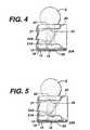
- Figs. 4and depict the flow of sample through channel 18 after it has broken through stop junction 21.
- the sampleis stopped at stop junction 21A.
- Fig. 5sample has passed through stop junction 21A at its two ends. The breakthroughs occur there, because although the angles at the two ends are greater than 90°, they are smaller than the angle (i.e., the supplement of the angle that points toward 26) at the center of serration 24A.
- Fig. 6is an exploded perspective view of an embodiment of the present invention.
- the diagnostic device 30has a top layer 32 and bottom layer 34 sandwiching intermediate layer 36. Elements of the device are formed by the layers, together with cutouts in them. Depicted in Fig. 6 are sample inlet 38, formed by coaligned holes in intermediate layer 66 and top layer 32; first capillary channel 40, for conveying sample from sample inlet 38 to branching point 42; and capillary connecting channel 44, for conveying sample through measurement area 46 to a first stop junction 48. Stop junction 48 is formed by the intersection of the capillary neck, at the end of measurement area 46, and the coinciding holes 48A, 48B, and 48C in intermediate layer 36, top layer 32, and bottom layer 34, respectively.
- Measurement area 46preferably contains a reagent 50.
- Cutout 58.is part of a bladder that includes the adjoining regions of top layer 32 and bottom layer 34.
- Capillary bypass channel 52provides an alternate path from branching point 42 to overflow region 54.
- a stop junction 56 in bypass channel 52impedes flow into overflow region 54.
- Stop junction 56is formed by the intersection of capillary bypass channel 52 and the coinciding holes 56A, 56B, and 56C in intermediate layer 36, top layer 32, and bottom layer 34, respectively. (Either hole 56B or 56C can be omitted). Note that stop junctions 48 and 56 also require seals 48D, 48E, and 56D, 56E, respectively.
- Fig. 7is a top plan view of the device of Fig. 6.
- the device depicted in Figs. 6 and 7is particularly well suited for measuring blood-clotting time - "prothrombin time” or "PT time” - and details regarding such a device appear below.
- the modifications needed to adapt the device for other medical diagnostic applicationsrequire no more than routine experimentation.
- sampleis applied to sample port 38 after bladder 58 has been compressed.
- the region of top layer 32 and/or bottom layer 34 that adjoins the cutout for bladder 58must be resilient, to permit bladder 58 to be compressed. When the bladder is released, suction draws sample through first capillary channel 40 to branching point 42 and through capillary connecting channel 44 to measurement area 46.
- the volume of bladder 58is preferably at least about equal to the combined volume of first channel 40, connecting channel 44, capillary bypass channel 52, and measurement area 46.
- the measurement methodis optical, and the measurement area 46 is to be illuminated from below, bottom layer 34 must be transparent where it adjoins measurement area 46.
- reagent 50contains thromboplastin that is free of bulking reagents normally found in lyophilized reagents.
- sampleis drawn into the device by suction, caused by decompression of bladder 88.
- stop junction 48sample flow stops.
- Figs. 7A, 7B, and 7Cdepict a time sequence during which a sample is drawn into device 30 for the measurement.
- Fig. 7Adepicts the situation after a user has applied a sample to the strip, while bladder 58 is compressed. This can be accomplished by applying one or more drops of blood.
- Fig. 7Bdepicts the situation after the bladder is decompressed.
- the resulting reduced pressure in the first channel 40 and connecting channel 44draws the sample initially into the measurement area 46.
- stop junction 48When the sample reaches stop junction 48, the sample encounters a back pressure that causes it to stop and causes additional sample to be drawn into the bypass channel toward stop junction 56.
- stop junction 56is "weaker” than stop junction 48, because it has an angle A that points toward branching point 42. (See Figs. 1-5).
- weak stop junction 56performs two functions. It first impedes the flow of sample into overflow region 54, thus permitting measurement area 46 to fill rapidly. Second, it permits any excess sample to flow through it (after measurement area 46 is full) to relieve any pressure difference remaining on the two sides of stop junction 48. Such a pressure difference could cause sample to "leak” through stop junction 48, causing movement of sample through the measurement area, which is undesirable, for the reason discussed earlier.
- Fig. 7Cdepicts the situation when an equilibrium has been established among the pressures on the sample surfaces - atmospheric pressure on the sample in inlet 38 and the pressure on the free surfaces in overflow region 54 and stop junction 48.
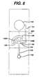
- Fig. 8depicts a preferred embodiment of the present device that includes three measurement areas.
- measurement area 146contains thromboplastin.
- measurement areas 146A and 146Bcontain controls, more preferably, the controls described below.
- Area 146Acontains thromboplastin, bovine eluate, and recombinant Factor VIIa.
- the compositionis selected to normalize the clotting time of a blood sample by counteracting the effect of an anticoagulant, such as warfarin.
- Measurement area 146Bcontains thromboplastin and bovine eluate alone, to partially overcome the effect of an anticoagulent.
- three measurementsare made on the strip.
- PT time of the samplethe measurement of primary interest, is measured on area 146. However, that measurement is validated only when measurements on areas 146A and 146B yield results within a predetermined range. If either or both of these control measurements are outside the range, then a retest is indicated.
- Extended stop junction 148stops flow in all three measurement areas. Stop junction 156, in bypass channel 152, functions as described above.
Landscapes
- Health & Medical Sciences (AREA)
- Life Sciences & Earth Sciences (AREA)
- Engineering & Computer Science (AREA)
- Biomedical Technology (AREA)
- Immunology (AREA)
- Chemical & Material Sciences (AREA)
- Hematology (AREA)
- Physics & Mathematics (AREA)
- Molecular Biology (AREA)
- Urology & Nephrology (AREA)
- Biochemistry (AREA)
- Food Science & Technology (AREA)
- Medicinal Chemistry (AREA)
- Analytical Chemistry (AREA)
- General Health & Medical Sciences (AREA)
- General Physics & Mathematics (AREA)
- Pathology (AREA)
- Biophysics (AREA)
- Ecology (AREA)
- Biotechnology (AREA)
- Cell Biology (AREA)
- Microbiology (AREA)
- Investigating Or Analysing Biological Materials (AREA)
Description
Claims (10)
- A medical diagnostic device (30), for measuring an analyte concentration orproperty of a biological fluid, comprisingcharacterised in that the second direction is normal to the plane of the layers (32, 34, 36),and the boundary region forms an angle in the plane of the layers (32, 34, 36).a) a top layer (32), a bottom layer (34) and an intermediate layer (36);b) a sample inlet (38) for introducing a sample of the biological fluid into thedevice;c) a first capillary channel (40) for conveying the sample from the inlet to abranching point (42);d) a capillary connecting channel (44) for conveying a first part of the samplefrom the branching point (42) through a measurement area (46), in which ismeasured a physical parameter of the sample that is related to the analyteconcentration or property of the fluid, and to a first stop junction(48);e) a capillary bypass channel (52) for conveying a second part of the sample ina first direction from a first region, proximate to the branching point (42), toan overflow region (54), distal to the branching point, the first region havinga capillary dimension in a second direction substantially perpendicular tothe first direction;f) a second stop junction (56) in the bypass channel, comprising a boundaryregion thatwhereby any excess sample that enters the sample inlet (38) will pass through thesecond stop junction (56) into the overflow region (54);i) separates the first and overflow regions,ii) has a second predetermined dimension in the second direction that isgreater than the capillary dimension, andiii) forms an angle that points toward the first region,
- The device of claim 1, further comprising a suction device (58), in fluidcommunication with the first (48) and second stop junctions (52), for drawing sample fromthe sample inlet (38) toward stop junctions.
- The device of claim 2, in which at least one of the first layer (32) and the secondlayer (34) has a resilient region over at least a part of its area, separated by an intermediatelayer (36), and in whicha) cutouts in the layers form, with the layers, the sample inlet (38), firstchannel (40), connecting channel (44), measurement area (46), and bypass channel (52);b) the suction device comprises a bladder (58) thati) is distal from the sample inlet,ii) comprises at least a part of the resilient region, andiii) has a volume that is at least about equal to the combined volume ofthe first channel, measurement area, connecting channel, and bypass channel, andc) the first and second stop junctions comprise coinciding holes (56A, 56B,56C) in the first, second, and intermediate layers that are sandwiched by a third layer andfourth layer.
- The device of claim 3 in which at least the first (32) or second layer (34) issubstantially transparent adjoining the measurement area (46), and the physical parameterthat is measured is optical transmission.
- The device of claim 3 or claim 4 in which the physical parameter of the sampleundergoes a change in the measurement area (46).
- The device of claim 5 in which the measurement area contains a composition thatfacilitates blood clotting, the biological fluid is whole blood, and the property beingmeasured is prothrombin time.
- The device of claim 6 in which the composition comprises thromboplastin.
- The device of claim 6 or claim 7 further comprising at least one additional fluidicpath from the branching point to the bladder, each such alternate path including acorresponding measurement area and stop junction.
- The device of claim 8 in which a first alternate path is to a measurement area that overcomes the effect of an anticoagulant and a second alternate path is to a measurementarea that partially overcomes the effect of an anticoagulant.
- The device of claim 9 in which the measurement area in the first alternate pathcomprises thromboplastin, bovine eluate, and recombinant Factor VIIa and themeasurement area in the second alternate path comprises thromboplastin and bovine eluate.
Priority Applications (1)
| Application Number | Priority Date | Filing Date | Title |
|---|---|---|---|
| DK01937160TDK1280602T3 (en) | 2000-03-31 | 2001-03-22 | Capillary flow control in a diagnostic fluid device |
Applications Claiming Priority (3)
| Application Number | Priority Date | Filing Date | Title |
|---|---|---|---|
| US09/541,376US6908593B1 (en) | 2000-03-31 | 2000-03-31 | Capillary flow control in a fluidic diagnostic device |
| US541376 | 2000-03-31 | ||
| PCT/US2001/009237WO2001075433A2 (en) | 2000-03-31 | 2001-03-22 | Capillary flow control in a fluidic diagnostic device |
Publications (2)
| Publication Number | Publication Date |
|---|---|
| EP1280602A2 EP1280602A2 (en) | 2003-02-05 |
| EP1280602B1true EP1280602B1 (en) | 2005-05-11 |
Family
ID=24159321
Family Applications (1)
| Application Number | Title | Priority Date | Filing Date |
|---|---|---|---|
| EP01937160AExpired - LifetimeEP1280602B1 (en) | 2000-03-31 | 2001-03-22 | Capillary flow control in a fluidic diagnostic device |
Country Status (20)
| Country | Link |
|---|---|
| US (1) | US6908593B1 (en) |
| EP (1) | EP1280602B1 (en) |
| JP (1) | JP2003529763A (en) |
| KR (1) | KR20020087448A (en) |
| CN (1) | CN1238112C (en) |
| AR (1) | AR028529A1 (en) |
| AT (1) | ATE295227T1 (en) |
| AU (2) | AU6292301A (en) |
| CA (1) | CA2404521A1 (en) |
| CZ (1) | CZ20023250A3 (en) |
| DE (1) | DE60110781T2 (en) |
| ES (1) | ES2241828T3 (en) |
| IL (1) | IL151965A0 (en) |
| MX (1) | MXPA02009700A (en) |
| MY (1) | MY134187A (en) |
| PL (1) | PL357113A1 (en) |
| PT (1) | PT1280602E (en) |
| RU (1) | RU2238147C2 (en) |
| TW (1) | TW519567B (en) |
| WO (1) | WO2001075433A2 (en) |
Families Citing this family (94)
| Publication number | Priority date | Publication date | Assignee | Title |
|---|---|---|---|---|
| US6036924A (en) | 1997-12-04 | 2000-03-14 | Hewlett-Packard Company | Cassette of lancet cartridges for sampling blood |
| US6391005B1 (en) | 1998-03-30 | 2002-05-21 | Agilent Technologies, Inc. | Apparatus and method for penetration with shaft having a sensor for sensing penetration depth |
| US8641644B2 (en) | 2000-11-21 | 2014-02-04 | Sanofi-Aventis Deutschland Gmbh | Blood testing apparatus having a rotatable cartridge with multiple lancing elements and testing means |
| DE10057832C1 (en) | 2000-11-21 | 2002-02-21 | Hartmann Paul Ag | Blood analysis device has syringe mounted in casing, annular mounting carrying needles mounted behind test strip and being swiveled so that needle can be pushed through strip and aperture in casing to take blood sample |
| US20040099310A1 (en)* | 2001-01-05 | 2004-05-27 | Per Andersson | Microfluidic device |
| CA2441206A1 (en) | 2001-03-19 | 2002-09-26 | Gyros Ab | Characterization of reaction variables |
| US9226699B2 (en) | 2002-04-19 | 2016-01-05 | Sanofi-Aventis Deutschland Gmbh | Body fluid sampling module with a continuous compression tissue interface surface |
| AU2002344825A1 (en) | 2001-06-12 | 2002-12-23 | Pelikan Technologies, Inc. | Method and apparatus for improving success rate of blood yield from a fingerstick |
| US7041068B2 (en) | 2001-06-12 | 2006-05-09 | Pelikan Technologies, Inc. | Sampling module device and method |
| US9427532B2 (en) | 2001-06-12 | 2016-08-30 | Sanofi-Aventis Deutschland Gmbh | Tissue penetration device |
| US9795747B2 (en) | 2010-06-02 | 2017-10-24 | Sanofi-Aventis Deutschland Gmbh | Methods and apparatus for lancet actuation |
| US8337419B2 (en) | 2002-04-19 | 2012-12-25 | Sanofi-Aventis Deutschland Gmbh | Tissue penetration device |
| WO2002101359A2 (en) | 2001-06-12 | 2002-12-19 | Pelikan Technologies, Inc. | Integrated blood sampling analysis system with multi-use sampling module |
| EP1395185B1 (en) | 2001-06-12 | 2010-10-27 | Pelikan Technologies Inc. | Electric lancet actuator |
| US7344507B2 (en) | 2002-04-19 | 2008-03-18 | Pelikan Technologies, Inc. | Method and apparatus for lancet actuation |
| JP4272051B2 (en) | 2001-06-12 | 2009-06-03 | ペリカン テクノロジーズ インコーポレイテッド | Blood sampling apparatus and method |
| JP4209767B2 (en) | 2001-06-12 | 2009-01-14 | ペリカン テクノロジーズ インコーポレイテッド | Self-optimized cutting instrument with adaptive means for temporary changes in skin properties |
| US7981056B2 (en) | 2002-04-19 | 2011-07-19 | Pelikan Technologies, Inc. | Methods and apparatus for lancet actuation |
| US7749174B2 (en) | 2001-06-12 | 2010-07-06 | Pelikan Technologies, Inc. | Method and apparatus for lancet launching device intergrated onto a blood-sampling cartridge |
| US7344894B2 (en) | 2001-10-16 | 2008-03-18 | Agilent Technologies, Inc. | Thermal regulation of fluidic samples within a diagnostic cartridge |
| DE20202056U1 (en) | 2002-02-12 | 2002-07-04 | Dr. Müller Gerätebau GmbH, 01705 Freital | Microchip for determining the concentration of substances in liquid components |
| US6673617B2 (en)* | 2002-03-14 | 2004-01-06 | Lifescan, Inc. | Test strip qualification system |
| US6682933B2 (en) | 2002-03-14 | 2004-01-27 | Lifescan, Inc. | Test strip qualification system |
| US9248267B2 (en) | 2002-04-19 | 2016-02-02 | Sanofi-Aventis Deustchland Gmbh | Tissue penetration device |
| US7297122B2 (en) | 2002-04-19 | 2007-11-20 | Pelikan Technologies, Inc. | Method and apparatus for penetrating tissue |
| US7717863B2 (en) | 2002-04-19 | 2010-05-18 | Pelikan Technologies, Inc. | Method and apparatus for penetrating tissue |
| US7524293B2 (en) | 2002-04-19 | 2009-04-28 | Pelikan Technologies, Inc. | Method and apparatus for penetrating tissue |
| US7563232B2 (en) | 2002-04-19 | 2009-07-21 | Pelikan Technologies, Inc. | Method and apparatus for penetrating tissue |
| US8221334B2 (en) | 2002-04-19 | 2012-07-17 | Sanofi-Aventis Deutschland Gmbh | Method and apparatus for penetrating tissue |
| US7485128B2 (en) | 2002-04-19 | 2009-02-03 | Pelikan Technologies, Inc. | Method and apparatus for penetrating tissue |
| US7141058B2 (en) | 2002-04-19 | 2006-11-28 | Pelikan Technologies, Inc. | Method and apparatus for a body fluid sampling device using illumination |
| US7976476B2 (en) | 2002-04-19 | 2011-07-12 | Pelikan Technologies, Inc. | Device and method for variable speed lancet |
| US7481776B2 (en) | 2002-04-19 | 2009-01-27 | Pelikan Technologies, Inc. | Method and apparatus for penetrating tissue |
| US7582099B2 (en) | 2002-04-19 | 2009-09-01 | Pelikan Technologies, Inc | Method and apparatus for penetrating tissue |
| US8267870B2 (en) | 2002-04-19 | 2012-09-18 | Sanofi-Aventis Deutschland Gmbh | Method and apparatus for body fluid sampling with hybrid actuation |
| US7674232B2 (en) | 2002-04-19 | 2010-03-09 | Pelikan Technologies, Inc. | Method and apparatus for penetrating tissue |
| US9795334B2 (en) | 2002-04-19 | 2017-10-24 | Sanofi-Aventis Deutschland Gmbh | Method and apparatus for penetrating tissue |
| WO2003088824A2 (en) | 2002-04-19 | 2003-10-30 | Pelikan Technologies, Inc. | Device and method for variable speed lancet |
| US7491178B2 (en) | 2002-04-19 | 2009-02-17 | Pelikan Technologies, Inc. | Method and apparatus for penetrating tissue |
| US7648468B2 (en) | 2002-04-19 | 2010-01-19 | Pelikon Technologies, Inc. | Method and apparatus for penetrating tissue |
| US7232451B2 (en) | 2002-04-19 | 2007-06-19 | Pelikan Technologies, Inc. | Method and apparatus for penetrating tissue |
| US7331931B2 (en) | 2002-04-19 | 2008-02-19 | Pelikan Technologies, Inc. | Method and apparatus for penetrating tissue |
| US7410468B2 (en) | 2002-04-19 | 2008-08-12 | Pelikan Technologies, Inc. | Method and apparatus for penetrating tissue |
| US7244265B2 (en) | 2002-04-19 | 2007-07-17 | Pelikan Technologies, Inc. | Method and apparatus for penetrating tissue |
| US7371247B2 (en) | 2002-04-19 | 2008-05-13 | Pelikan Technologies, Inc | Method and apparatus for penetrating tissue |
| US7229458B2 (en) | 2002-04-19 | 2007-06-12 | Pelikan Technologies, Inc. | Method and apparatus for penetrating tissue |
| US7708701B2 (en) | 2002-04-19 | 2010-05-04 | Pelikan Technologies, Inc. | Method and apparatus for a multi-use body fluid sampling device |
| US7547287B2 (en) | 2002-04-19 | 2009-06-16 | Pelikan Technologies, Inc. | Method and apparatus for penetrating tissue |
| US7909778B2 (en) | 2002-04-19 | 2011-03-22 | Pelikan Technologies, Inc. | Method and apparatus for penetrating tissue |
| US8702624B2 (en) | 2006-09-29 | 2014-04-22 | Sanofi-Aventis Deutschland Gmbh | Analyte measurement device with a single shot actuator |
| US7291117B2 (en) | 2002-04-19 | 2007-11-06 | Pelikan Technologies, Inc. | Method and apparatus for penetrating tissue |
| US7892183B2 (en) | 2002-04-19 | 2011-02-22 | Pelikan Technologies, Inc. | Method and apparatus for body fluid sampling and analyte sensing |
| US8784335B2 (en) | 2002-04-19 | 2014-07-22 | Sanofi-Aventis Deutschland Gmbh | Body fluid sampling device with a capacitive sensor |
| US7901362B2 (en) | 2002-04-19 | 2011-03-08 | Pelikan Technologies, Inc. | Method and apparatus for penetrating tissue |
| US7374544B2 (en) | 2002-04-19 | 2008-05-20 | Pelikan Technologies, Inc. | Method and apparatus for penetrating tissue |
| US9314194B2 (en) | 2002-04-19 | 2016-04-19 | Sanofi-Aventis Deutschland Gmbh | Tissue penetration device |
| US8579831B2 (en) | 2002-04-19 | 2013-11-12 | Sanofi-Aventis Deutschland Gmbh | Method and apparatus for penetrating tissue |
| US8574895B2 (en) | 2002-12-30 | 2013-11-05 | Sanofi-Aventis Deutschland Gmbh | Method and apparatus using optical techniques to measure analyte levels |
| US7850621B2 (en) | 2003-06-06 | 2010-12-14 | Pelikan Technologies, Inc. | Method and apparatus for body fluid sampling and analyte sensing |
| WO2006001797A1 (en) | 2004-06-14 | 2006-01-05 | Pelikan Technologies, Inc. | Low pain penetrating |
| EP1635700B1 (en) | 2003-06-13 | 2016-03-09 | Sanofi-Aventis Deutschland GmbH | Apparatus for a point of care device |
| US7604721B2 (en) | 2003-06-20 | 2009-10-20 | Roche Diagnostics Operations, Inc. | System and method for coding information on a biosensor test strip |
| US7452457B2 (en) | 2003-06-20 | 2008-11-18 | Roche Diagnostics Operations, Inc. | System and method for analyte measurement using dose sufficiency electrodes |
| US7597793B2 (en) | 2003-06-20 | 2009-10-06 | Roche Operations Ltd. | System and method for analyte measurement employing maximum dosing time delay |
| US8282576B2 (en) | 2003-09-29 | 2012-10-09 | Sanofi-Aventis Deutschland Gmbh | Method and apparatus for an improved sample capture device |
| EP1680014A4 (en) | 2003-10-14 | 2009-01-21 | Pelikan Technologies Inc | METHOD AND DEVICE FOR A VARIABLE USER INTERFACE |
| GB0329220D0 (en)* | 2003-12-17 | 2004-01-21 | Inverness Medical Switzerland | System |
| US7822454B1 (en) | 2005-01-03 | 2010-10-26 | Pelikan Technologies, Inc. | Fluid sampling device with improved analyte detecting member configuration |
| US8668656B2 (en) | 2003-12-31 | 2014-03-11 | Sanofi-Aventis Deutschland Gmbh | Method and apparatus for improving fluidic flow and sample capture |
| US7807043B2 (en)* | 2004-02-23 | 2010-10-05 | Oakville Hong Kong Company Limited | Microfluidic test device |
| US7588724B2 (en) | 2004-03-05 | 2009-09-15 | Bayer Healthcare Llc | Mechanical device for mixing a fluid sample with a treatment solution |
| US20050249641A1 (en)* | 2004-04-08 | 2005-11-10 | Boehringer Ingelheim Microparts Gmbh | Microstructured platform and method for manipulating a liquid |
| WO2005108991A2 (en) | 2004-05-04 | 2005-11-17 | Metrika, Inc | Mechanical cartridge with test strip fluid control features for use in a fluid analyte meter |
| WO2006011062A2 (en) | 2004-05-20 | 2006-02-02 | Albatros Technologies Gmbh & Co. Kg | Printable hydrogel for biosensors |
| WO2005120365A1 (en) | 2004-06-03 | 2005-12-22 | Pelikan Technologies, Inc. | Method and apparatus for a fluid sampling device |
| US9775553B2 (en) | 2004-06-03 | 2017-10-03 | Sanofi-Aventis Deutschland Gmbh | Method and apparatus for a fluid sampling device |
| US7569126B2 (en) | 2004-06-18 | 2009-08-04 | Roche Diagnostics Operations, Inc. | System and method for quality assurance of a biosensor test strip |
| US7556723B2 (en) | 2004-06-18 | 2009-07-07 | Roche Diagnostics Operations, Inc. | Electrode design for biosensor |
| US8652831B2 (en) | 2004-12-30 | 2014-02-18 | Sanofi-Aventis Deutschland Gmbh | Method and apparatus for analyte measurement test time |
| US8133741B2 (en) | 2005-10-26 | 2012-03-13 | General Electric Company | Methods and systems for delivery of fluidic samples to sensor arrays |
| US7723120B2 (en)* | 2005-10-26 | 2010-05-25 | General Electric Company | Optical sensor array system and method for parallel processing of chemical and biochemical information |
| US7771655B2 (en)* | 2006-07-12 | 2010-08-10 | Bayer Healthcare Llc | Mechanical device for mixing a fluid sample with a treatment solution |
| EP2040073A1 (en)* | 2007-09-20 | 2009-03-25 | Iline Microsystems, S.L. | Microfluidic device and method for fluid clotting time determination |
| US7766846B2 (en)* | 2008-01-28 | 2010-08-03 | Roche Diagnostics Operations, Inc. | Rapid blood expression and sampling |
| EP2265324B1 (en) | 2008-04-11 | 2015-01-28 | Sanofi-Aventis Deutschland GmbH | Integrated analyte measurement system |
| JP5213952B2 (en)* | 2008-04-18 | 2013-06-19 | パナソニック株式会社 | Liquid sample analysis method |
| US9375169B2 (en) | 2009-01-30 | 2016-06-28 | Sanofi-Aventis Deutschland Gmbh | Cam drive for managing disposable penetrating member actions with a single motor and motor and control system |
| GB201005357D0 (en) | 2010-03-30 | 2010-05-12 | Menai Medical Technologies Ltd | Sampling plate |
| GB201005359D0 (en)* | 2010-03-30 | 2010-05-12 | Menai Medical Technologies Ltd | Sampling plate |
| US8965476B2 (en) | 2010-04-16 | 2015-02-24 | Sanofi-Aventis Deutschland Gmbh | Tissue penetration device |
| CA2898201C (en) | 2012-01-16 | 2023-09-26 | Abram Scientific, Inc. | Methods, devices, and systems for measuring physical properties of fluid |
| US20180275058A1 (en)* | 2015-09-02 | 2018-09-27 | SeLux Diagnostics, Inc. | Systems and methods for multiplexed detection of biomarkers |
| CN109415722A (en) | 2016-01-29 | 2019-03-01 | 普瑞珍生物系统公司 | Isotachophoresis for nucleic acid purification |
| CA3071816A1 (en)* | 2017-08-02 | 2019-02-07 | Purigen Biosystems, Inc. | Systems, devices, and methods for isotachophoresis |
Citations (2)
| Publication number | Priority date | Publication date | Assignee | Title |
|---|---|---|---|---|
| US4136036A (en)* | 1976-04-07 | 1979-01-23 | Eastman Kodak Company | Collection and dispensing device for non-pressurized liquids |
| US5230866A (en)* | 1991-03-01 | 1993-07-27 | Biotrack, Inc. | Capillary stop-flow junction having improved stability against accidental fluid flow |
Family Cites Families (24)
| Publication number | Priority date | Publication date | Assignee | Title |
|---|---|---|---|---|
| JPS5912135B2 (en) | 1977-09-28 | 1984-03-21 | 松下電器産業株式会社 | enzyme electrode |
| US4254083A (en) | 1979-07-23 | 1981-03-03 | Eastman Kodak Company | Structural configuration for transport of a liquid drop through an ingress aperture |
| US4426451A (en) | 1981-01-28 | 1984-01-17 | Eastman Kodak Company | Multi-zoned reaction vessel having pressure-actuatable control means between zones |
| EP0078636B2 (en) | 1981-10-23 | 1997-04-02 | MediSense, Inc. | Sensor for components of a liquid mixture |
| US4868129A (en) | 1987-08-27 | 1989-09-19 | Biotrack Inc. | Apparatus and method for dilution and mixing of liquid samples |
| US5104813A (en)* | 1989-04-13 | 1992-04-14 | Biotrack, Inc. | Dilution and mixing cartridge |
| AU4047493A (en) | 1992-04-02 | 1993-11-08 | Abaxis, Inc. | Analytical rotor with dye mixing chamber |
| US5223219A (en)* | 1992-04-10 | 1993-06-29 | Biotrack, Inc. | Analytical cartridge and system for detecting analytes in liquid samples |
| US5222808A (en)* | 1992-04-10 | 1993-06-29 | Biotrack, Inc. | Capillary mixing device |
| US5885527A (en) | 1992-05-21 | 1999-03-23 | Biosite Diagnostics, Inc. | Diagnostic devices and apparatus for the controlled movement of reagents without membrances |
| US5447440A (en) | 1993-10-28 | 1995-09-05 | I-Stat Corporation | Apparatus for assaying viscosity changes in fluid samples and method of conducting same |
| US5700695A (en) | 1994-06-30 | 1997-12-23 | Zia Yassinzadeh | Sample collection and manipulation method |
| US5627041A (en) | 1994-09-02 | 1997-05-06 | Biometric Imaging, Inc. | Disposable cartridge for an assay of a biological sample |
| AUPN661995A0 (en) | 1995-11-16 | 1995-12-07 | Memtec America Corporation | Electrochemical cell 2 |
| US20010055812A1 (en) | 1995-12-05 | 2001-12-27 | Alec Mian | Devices and method for using centripetal acceleration to drive fluid movement in a microfluidics system with on-board informatics |
| US5736404A (en) | 1995-12-27 | 1998-04-07 | Zia Yassinzadeh | Flow detection appartus and method |
| US6001307A (en) | 1996-04-26 | 1999-12-14 | Kyoto Daiichi Kagaku Co., Ltd. | Device for analyzing a sample |
| JP3498201B2 (en)* | 1997-08-27 | 2004-02-16 | アークレイ株式会社 | Vacuum generator and sample analyzer using the same |
| RU2123008C1 (en)* | 1997-10-28 | 1998-12-10 | Институт молекулярной биологии имени В.А.Энгельгардта РАН | Method of heparin assay |
| US5997817A (en) | 1997-12-05 | 1999-12-07 | Roche Diagnostics Corporation | Electrochemical biosensor test strip |
| AU739563B2 (en) | 1998-03-11 | 2001-10-18 | Boehringer Ingelheim Microparts Gmbh | Sample support |
| US6084660A (en)* | 1998-07-20 | 2000-07-04 | Lifescan, Inc. | Initiation of an analytical measurement in blood |
| US6521182B1 (en) | 1998-07-20 | 2003-02-18 | Lifescan, Inc. | Fluidic device for medical diagnostics |
| US6261519B1 (en)* | 1998-07-20 | 2001-07-17 | Lifescan, Inc. | Medical diagnostic device with enough-sample indicator |
- 2000
- 2000-03-31USUS09/541,376patent/US6908593B1/ennot_activeExpired - Lifetime
- 2001
- 2001-03-22CACA002404521Apatent/CA2404521A1/ennot_activeAbandoned
- 2001-03-22ESES01937160Tpatent/ES2241828T3/ennot_activeExpired - Lifetime
- 2001-03-22JPJP2001572861Apatent/JP2003529763A/enactivePending
- 2001-03-22EPEP01937160Apatent/EP1280602B1/ennot_activeExpired - Lifetime
- 2001-03-22WOPCT/US2001/009237patent/WO2001075433A2/enactiveIP Right Grant
- 2001-03-22ATAT01937160Tpatent/ATE295227T1/enactive
- 2001-03-22AUAU6292301Apatent/AU6292301A/enactivePending
- 2001-03-22KRKR1020027012999Apatent/KR20020087448A/ennot_activeWithdrawn
- 2001-03-22MXMXPA02009700Apatent/MXPA02009700A/enunknown
- 2001-03-22ILIL15196501Apatent/IL151965A0/enunknown
- 2001-03-22PTPT01937160Tpatent/PT1280602E/enunknown
- 2001-03-22RURU2002125858Apatent/RU2238147C2/ennot_activeIP Right Cessation
- 2001-03-22DEDE60110781Tpatent/DE60110781T2/ennot_activeExpired - Lifetime
- 2001-03-22AUAU2001262923Apatent/AU2001262923B2/ennot_activeCeased
- 2001-03-22CNCNB018076386Apatent/CN1238112C/ennot_activeExpired - Fee Related
- 2001-03-22PLPL01357113Apatent/PL357113A1/ennot_activeApplication Discontinuation
- 2001-03-22CZCZ20023250Apatent/CZ20023250A3/enunknown
- 2001-03-29MYMYPI20011507Apatent/MY134187A/enunknown
- 2001-03-30ARARP010101547Apatent/AR028529A1/enunknown
- 2001-03-30TWTW090107579Apatent/TW519567B/ennot_activeIP Right Cessation
Patent Citations (2)
| Publication number | Priority date | Publication date | Assignee | Title |
|---|---|---|---|---|
| US4136036A (en)* | 1976-04-07 | 1979-01-23 | Eastman Kodak Company | Collection and dispensing device for non-pressurized liquids |
| US5230866A (en)* | 1991-03-01 | 1993-07-27 | Biotrack, Inc. | Capillary stop-flow junction having improved stability against accidental fluid flow |
Also Published As
| Publication number | Publication date |
|---|---|
| CN1422180A (en) | 2003-06-04 |
| AU6292301A (en) | 2001-10-15 |
| WO2001075433A3 (en) | 2002-03-14 |
| US6908593B1 (en) | 2005-06-21 |
| KR20020087448A (en) | 2002-11-22 |
| PT1280602E (en) | 2005-07-29 |
| AR028529A1 (en) | 2003-05-14 |
| IL151965A0 (en) | 2003-04-10 |
| DE60110781D1 (en) | 2005-06-16 |
| CA2404521A1 (en) | 2001-10-11 |
| TW519567B (en) | 2003-02-01 |
| MY134187A (en) | 2007-11-30 |
| EP1280602A2 (en) | 2003-02-05 |
| ATE295227T1 (en) | 2005-05-15 |
| DE60110781T2 (en) | 2006-02-23 |
| AU2001262923B2 (en) | 2005-02-03 |
| HK1050650A1 (en) | 2003-07-04 |
| CZ20023250A3 (en) | 2003-06-18 |
| PL357113A1 (en) | 2004-07-12 |
| MXPA02009700A (en) | 2004-09-06 |
| JP2003529763A (en) | 2003-10-07 |
| CN1238112C (en) | 2006-01-25 |
| RU2238147C2 (en) | 2004-10-20 |
| RU2002125858A (en) | 2004-03-10 |
| WO2001075433A2 (en) | 2001-10-11 |
| ES2241828T3 (en) | 2005-11-01 |
Similar Documents
| Publication | Publication Date | Title |
|---|---|---|
| EP1280602B1 (en) | Capillary flow control in a fluidic diagnostic device | |
| AU2001262923A1 (en) | Capillary flow control in a fluidic diagnostic device | |
| EP1268063B1 (en) | Capillary flow control in a medical diagnostic device | |
| EP1069427B1 (en) | Initiation of an analytical measurement procedure for blood | |
| AU2001280844B2 (en) | Strip holder for use in a test strip meter | |
| US6521182B1 (en) | Fluidic device for medical diagnostics | |
| US6261519B1 (en) | Medical diagnostic device with enough-sample indicator | |
| AU2001280844A1 (en) | Strip holder for use in a test strip meter | |
| HK1050650B (en) | Capillary flow control in a fluidic diagnostic device |
Legal Events
| Date | Code | Title | Description |
|---|---|---|---|
| PUAI | Public reference made under article 153(3) epc to a published international application that has entered the european phase | Free format text:ORIGINAL CODE: 0009012 | |
| 17P | Request for examination filed | Effective date:20021011 | |
| AK | Designated contracting states | Designated state(s):AT BE CH CY DE DK ES FI FR GB GR IE IT LI LU MC NL PT SE TR | |
| AX | Request for extension of the european patent | Extension state:AL LT LV MK RO SI | |
| RIN1 | Information on inventor provided before grant (corrected) | Inventor name:SHARTLE, ROBERT, JUSTICE | |
| 17Q | First examination report despatched | Effective date:20030904 | |
| GRAP | Despatch of communication of intention to grant a patent | Free format text:ORIGINAL CODE: EPIDOSNIGR1 | |
| GRAS | Grant fee paid | Free format text:ORIGINAL CODE: EPIDOSNIGR3 | |
| GRAA | (expected) grant | Free format text:ORIGINAL CODE: 0009210 | |
| AK | Designated contracting states | Kind code of ref document:B1 Designated state(s):AT BE CH CY DE DK ES FI FR GB GR IE IT LI LU MC NL PT SE TR | |
| REG | Reference to a national code | Ref country code:GB Ref legal event code:FG4D | |
| REG | Reference to a national code | Ref country code:CH Ref legal event code:EP | |
| REG | Reference to a national code | Ref country code:IE Ref legal event code:FG4D | |
| REF | Corresponds to: | Ref document number:60110781 Country of ref document:DE Date of ref document:20050616 Kind code of ref document:P | |
| REG | Reference to a national code | Ref country code:DK Ref legal event code:T3 | |
| REG | Reference to a national code | Ref country code:PT Ref legal event code:SC4A Effective date:20050525 | |
| REG | Reference to a national code | Ref country code:CH Ref legal event code:NV Representative=s name:E. BLUM & CO. PATENTANWAELTE | |
| REG | Reference to a national code | Ref country code:SE Ref legal event code:TRGR | |
| REG | Reference to a national code | Ref country code:GR Ref legal event code:EP Ref document number:20050402196 Country of ref document:GR | |
| REG | Reference to a national code | Ref country code:ES Ref legal event code:FG2A Ref document number:2241828 Country of ref document:ES Kind code of ref document:T3 | |
| REG | Reference to a national code | Ref country code:HK Ref legal event code:GR Ref document number:1050650 Country of ref document:HK | |
| PLBE | No opposition filed within time limit | Free format text:ORIGINAL CODE: 0009261 | |
| STAA | Information on the status of an ep patent application or granted ep patent | Free format text:STATUS: NO OPPOSITION FILED WITHIN TIME LIMIT | |
| ET | Fr: translation filed | ||
| 26N | No opposition filed | Effective date:20060214 | |
| REG | Reference to a national code | Ref country code:CH Ref legal event code:PFA Owner name:LIFESCAN, INC. Free format text:LIFESCAN, INC.#1000 GIBRALTAR DRIVE#MILPITAS, CALIFORNIA 95035 (US) -TRANSFER TO- LIFESCAN, INC.#1000 GIBRALTAR DRIVE#MILPITAS, CALIFORNIA 95035 (US) | |
| PG25 | Lapsed in a contracting state [announced via postgrant information from national office to epo] | Ref country code:CY Free format text:LAPSE BECAUSE OF FAILURE TO SUBMIT A TRANSLATION OF THE DESCRIPTION OR TO PAY THE FEE WITHIN THE PRESCRIBED TIME-LIMIT Effective date:20050511 | |
| REG | Reference to a national code | Ref country code:FR Ref legal event code:PLFP Year of fee payment:16 | |
| REG | Reference to a national code | Ref country code:FR Ref legal event code:PLFP Year of fee payment:17 | |
| REG | Reference to a national code | Ref country code:FR Ref legal event code:PLFP Year of fee payment:18 | |
| PGFP | Annual fee paid to national office [announced via postgrant information from national office to epo] | Ref country code:LU Payment date:20180308 Year of fee payment:18 Ref country code:FI Payment date:20180312 Year of fee payment:18 Ref country code:DK Payment date:20180312 Year of fee payment:18 | |
| PGFP | Annual fee paid to national office [announced via postgrant information from national office to epo] | Ref country code:BE Payment date:20180214 Year of fee payment:18 Ref country code:TR Payment date:20180322 Year of fee payment:18 Ref country code:PT Payment date:20180322 Year of fee payment:18 Ref country code:SE Payment date:20180313 Year of fee payment:18 Ref country code:MC Payment date:20180228 Year of fee payment:18 Ref country code:AT Payment date:20180226 Year of fee payment:18 | |
| PGFP | Annual fee paid to national office [announced via postgrant information from national office to epo] | Ref country code:IE Payment date:20190311 Year of fee payment:19 Ref country code:IT Payment date:20190326 Year of fee payment:19 Ref country code:DE Payment date:20190312 Year of fee payment:19 Ref country code:CH Payment date:20190314 Year of fee payment:19 Ref country code:GB Payment date:20190320 Year of fee payment:19 | |
| PGFP | Annual fee paid to national office [announced via postgrant information from national office to epo] | Ref country code:GR Payment date:20190213 Year of fee payment:19 Ref country code:FR Payment date:20190213 Year of fee payment:19 Ref country code:NL Payment date:20190313 Year of fee payment:19 | |
| PGFP | Annual fee paid to national office [announced via postgrant information from national office to epo] | Ref country code:ES Payment date:20190401 Year of fee payment:19 | |
| REG | Reference to a national code | Ref country code:DK Ref legal event code:EBP Effective date:20190331 | |
| REG | Reference to a national code | Ref country code:SE Ref legal event code:EUG | |
| PG25 | Lapsed in a contracting state [announced via postgrant information from national office to epo] | Ref country code:FI Free format text:LAPSE BECAUSE OF NON-PAYMENT OF DUE FEES Effective date:20190322 Ref country code:MC Free format text:LAPSE BECAUSE OF NON-PAYMENT OF DUE FEES Effective date:20190401 Ref country code:SE Free format text:LAPSE BECAUSE OF NON-PAYMENT OF DUE FEES Effective date:20190323 Ref country code:PT Free format text:LAPSE BECAUSE OF NON-PAYMENT OF DUE FEES Effective date:20190923 | |
| REG | Reference to a national code | Ref country code:AT Ref legal event code:MM01 Ref document number:295227 Country of ref document:AT Kind code of ref document:T Effective date:20190322 | |
| PG25 | Lapsed in a contracting state [announced via postgrant information from national office to epo] | Ref country code:LU Free format text:LAPSE BECAUSE OF NON-PAYMENT OF DUE FEES Effective date:20190322 | |
| REG | Reference to a national code | Ref country code:BE Ref legal event code:MM Effective date:20190331 | |
| PG25 | Lapsed in a contracting state [announced via postgrant information from national office to epo] | Ref country code:AT Free format text:LAPSE BECAUSE OF NON-PAYMENT OF DUE FEES Effective date:20190322 | |
| PG25 | Lapsed in a contracting state [announced via postgrant information from national office to epo] | Ref country code:BE Free format text:LAPSE BECAUSE OF NON-PAYMENT OF DUE FEES Effective date:20190331 | |
| PG25 | Lapsed in a contracting state [announced via postgrant information from national office to epo] | Ref country code:DK Free format text:LAPSE BECAUSE OF NON-PAYMENT OF DUE FEES Effective date:20190331 | |
| REG | Reference to a national code | Ref country code:DE Ref legal event code:R119 Ref document number:60110781 Country of ref document:DE | |
| REG | Reference to a national code | Ref country code:CH Ref legal event code:PL | |
| REG | Reference to a national code | Ref country code:NL Ref legal event code:MM Effective date:20200401 | |
| PG25 | Lapsed in a contracting state [announced via postgrant information from national office to epo] | Ref country code:NL Free format text:LAPSE BECAUSE OF NON-PAYMENT OF DUE FEES Effective date:20200401 | |
| PG25 | Lapsed in a contracting state [announced via postgrant information from national office to epo] | Ref country code:IE Free format text:LAPSE BECAUSE OF NON-PAYMENT OF DUE FEES Effective date:20200322 Ref country code:CH Free format text:LAPSE BECAUSE OF NON-PAYMENT OF DUE FEES Effective date:20200331 Ref country code:FR Free format text:LAPSE BECAUSE OF NON-PAYMENT OF DUE FEES Effective date:20200331 Ref country code:DE Free format text:LAPSE BECAUSE OF NON-PAYMENT OF DUE FEES Effective date:20201001 Ref country code:LI Free format text:LAPSE BECAUSE OF NON-PAYMENT OF DUE FEES Effective date:20200331 Ref country code:GR Free format text:LAPSE BECAUSE OF NON-PAYMENT OF DUE FEES Effective date:20201008 | |
| GBPC | Gb: european patent ceased through non-payment of renewal fee | Effective date:20200322 | |
| PG25 | Lapsed in a contracting state [announced via postgrant information from national office to epo] | Ref country code:GB Free format text:LAPSE BECAUSE OF NON-PAYMENT OF DUE FEES Effective date:20200322 | |
| REG | Reference to a national code | Ref country code:ES Ref legal event code:FD2A Effective date:20210804 | |
| PG25 | Lapsed in a contracting state [announced via postgrant information from national office to epo] | Ref country code:IT Free format text:LAPSE BECAUSE OF NON-PAYMENT OF DUE FEES Effective date:20200322 | |
| PG25 | Lapsed in a contracting state [announced via postgrant information from national office to epo] | Ref country code:ES Free format text:LAPSE BECAUSE OF NON-PAYMENT OF DUE FEES Effective date:20200323 | |
| PG25 | Lapsed in a contracting state [announced via postgrant information from national office to epo] | Ref country code:TR Free format text:LAPSE BECAUSE OF NON-PAYMENT OF DUE FEES Effective date:20190322 |