EP1279515B1 - Ink cartridge for ink jet printer - Google Patents
Ink cartridge for ink jet printerDownload PDFInfo
- Publication number
- EP1279515B1 EP1279515B1EP20020024288EP02024288AEP1279515B1EP 1279515 B1EP1279515 B1EP 1279515B1EP 20020024288EP20020024288EP 20020024288EP 02024288 AEP02024288 AEP 02024288AEP 1279515 B1EP1279515 B1EP 1279515B1
- Authority
- EP
- European Patent Office
- Prior art keywords
- ink
- membrane
- valve seat
- chamber
- valve body
- Prior art date
- Legal status (The legal status is an assumption and is not a legal conclusion. Google has not performed a legal analysis and makes no representation as to the accuracy of the status listed.)
- Expired - Lifetime
Links
- 239000012528membraneSubstances0.000claimsdescription145
- 238000007639printingMethods0.000claimsdescription25
- 239000012530fluidSubstances0.000claimsdescription13
- 238000004891communicationMethods0.000claimsdescription10
- 230000000087stabilizing effectEffects0.000claimsdescription7
- 229920001971elastomerPolymers0.000claimsdescription5
- 238000005192partitionMethods0.000claimsdescription5
- 230000000670limiting effectEffects0.000claimsdescription3
- 239000000463materialSubstances0.000claimsdescription3
- 239000000806elastomerSubstances0.000claimsdescription2
- 239000011148porous materialSubstances0.000description9
- 230000004044responseEffects0.000description8
- 230000003247decreasing effectEffects0.000description7
- 238000007667floatingMethods0.000description7
- 230000007613environmental effectEffects0.000description5
- 238000010276constructionMethods0.000description4
- 230000007423decreaseEffects0.000description4
- 230000008859changeEffects0.000description3
- 230000002950deficientEffects0.000description2
- 238000007599dischargingMethods0.000description2
- 238000005429filling processMethods0.000description2
- 230000006870functionEffects0.000description2
- 230000014759maintenance of locationEffects0.000description2
- 238000004519manufacturing processMethods0.000description2
- 238000000034methodMethods0.000description2
- 230000002093peripheral effectEffects0.000description2
- 230000002829reductive effectEffects0.000description2
- 230000001105regulatory effectEffects0.000description2
- 238000007789sealingMethods0.000description2
- 235000001674Agaricus brunnescensNutrition0.000description1
- 230000002411adverseEffects0.000description1
- 230000015572biosynthetic processEffects0.000description1
- 230000001276controlling effectEffects0.000description1
- 230000001419dependent effectEffects0.000description1
- 238000001035dryingMethods0.000description1
- 230000000694effectsEffects0.000description1
- 230000005489elastic deformationEffects0.000description1
- 230000005484gravityEffects0.000description1
- 230000006872improvementEffects0.000description1
- 238000003780insertionMethods0.000description1
- 230000037431insertionEffects0.000description1
- 230000007246mechanismEffects0.000description1
- 230000000149penetrating effectEffects0.000description1
- 230000000717retained effectEffects0.000description1
- 239000002699waste materialSubstances0.000description1
Images


Classifications
- B—PERFORMING OPERATIONS; TRANSPORTING
- B41—PRINTING; LINING MACHINES; TYPEWRITERS; STAMPS
- B41J—TYPEWRITERS; SELECTIVE PRINTING MECHANISMS, i.e. MECHANISMS PRINTING OTHERWISE THAN FROM A FORME; CORRECTION OF TYPOGRAPHICAL ERRORS
- B41J2/00—Typewriters or selective printing mechanisms characterised by the printing or marking process for which they are designed
- B41J2/005—Typewriters or selective printing mechanisms characterised by the printing or marking process for which they are designed characterised by bringing liquid or particles selectively into contact with a printing material
- B41J2/01—Ink jet
- B41J2/17—Ink jet characterised by ink handling
- B41J2/175—Ink supply systems ; Circuit parts therefor
- B41J2/17503—Ink cartridges
- B41J2/17556—Means for regulating the pressure in the cartridge
- B—PERFORMING OPERATIONS; TRANSPORTING
- B41—PRINTING; LINING MACHINES; TYPEWRITERS; STAMPS
- B41J—TYPEWRITERS; SELECTIVE PRINTING MECHANISMS, i.e. MECHANISMS PRINTING OTHERWISE THAN FROM A FORME; CORRECTION OF TYPOGRAPHICAL ERRORS
- B41J2/00—Typewriters or selective printing mechanisms characterised by the printing or marking process for which they are designed
- B41J2/005—Typewriters or selective printing mechanisms characterised by the printing or marking process for which they are designed characterised by bringing liquid or particles selectively into contact with a printing material
- B41J2/01—Ink jet
- B41J2/17—Ink jet characterised by ink handling
- B41J2/175—Ink supply systems ; Circuit parts therefor
- B41J2/17503—Ink cartridges
- B41J2/17513—Inner structure
- B—PERFORMING OPERATIONS; TRANSPORTING
- B41—PRINTING; LINING MACHINES; TYPEWRITERS; STAMPS
- B41J—TYPEWRITERS; SELECTIVE PRINTING MECHANISMS, i.e. MECHANISMS PRINTING OTHERWISE THAN FROM A FORME; CORRECTION OF TYPOGRAPHICAL ERRORS
- B41J2/00—Typewriters or selective printing mechanisms characterised by the printing or marking process for which they are designed
- B41J2/005—Typewriters or selective printing mechanisms characterised by the printing or marking process for which they are designed characterised by bringing liquid or particles selectively into contact with a printing material
- B41J2/01—Ink jet
- B41J2/17—Ink jet characterised by ink handling
- B41J2/175—Ink supply systems ; Circuit parts therefor
- B41J2/17503—Ink cartridges
- B41J2/1752—Mounting within the printer
- B41J2/17523—Ink connection
- B—PERFORMING OPERATIONS; TRANSPORTING
- B41—PRINTING; LINING MACHINES; TYPEWRITERS; STAMPS
- B41J—TYPEWRITERS; SELECTIVE PRINTING MECHANISMS, i.e. MECHANISMS PRINTING OTHERWISE THAN FROM A FORME; CORRECTION OF TYPOGRAPHICAL ERRORS
- B41J2/00—Typewriters or selective printing mechanisms characterised by the printing or marking process for which they are designed
- B41J2/005—Typewriters or selective printing mechanisms characterised by the printing or marking process for which they are designed characterised by bringing liquid or particles selectively into contact with a printing material
- B41J2/01—Ink jet
- B41J2/17—Ink jet characterised by ink handling
- B41J2/175—Ink supply systems ; Circuit parts therefor
- B41J2/17503—Ink cartridges
- B41J2/17553—Outer structure
- B—PERFORMING OPERATIONS; TRANSPORTING
- B41—PRINTING; LINING MACHINES; TYPEWRITERS; STAMPS
- B41J—TYPEWRITERS; SELECTIVE PRINTING MECHANISMS, i.e. MECHANISMS PRINTING OTHERWISE THAN FROM A FORME; CORRECTION OF TYPOGRAPHICAL ERRORS
- B41J2/00—Typewriters or selective printing mechanisms characterised by the printing or marking process for which they are designed
- B41J2/005—Typewriters or selective printing mechanisms characterised by the printing or marking process for which they are designed characterised by bringing liquid or particles selectively into contact with a printing material
- B41J2/01—Ink jet
- B41J2/17—Ink jet characterised by ink handling
- B41J2/175—Ink supply systems ; Circuit parts therefor
- B41J2/17596—Ink pumps, ink valves
- F—MECHANICAL ENGINEERING; LIGHTING; HEATING; WEAPONS; BLASTING
- F16—ENGINEERING ELEMENTS AND UNITS; GENERAL MEASURES FOR PRODUCING AND MAINTAINING EFFECTIVE FUNCTIONING OF MACHINES OR INSTALLATIONS; THERMAL INSULATION IN GENERAL
- F16K—VALVES; TAPS; COCKS; ACTUATING-FLOATS; DEVICES FOR VENTING OR AERATING
- F16K15/00—Check valves
- F16K15/14—Check valves with flexible valve members
- F16K15/144—Check valves with flexible valve members the closure elements being fixed along all or a part of their periphery
- F16K15/145—Check valves with flexible valve members the closure elements being fixed along all or a part of their periphery the closure elements being shaped as a solids of revolution, e.g. cylindrical or conical
- G—PHYSICS
- G05—CONTROLLING; REGULATING
- G05D—SYSTEMS FOR CONTROLLING OR REGULATING NON-ELECTRIC VARIABLES
- G05D16/00—Control of fluid pressure
- G05D16/04—Control of fluid pressure without auxiliary power
- G05D16/06—Control of fluid pressure without auxiliary power the sensing element being a flexible membrane, yielding to pressure, e.g. diaphragm, bellows, capsule
- G05D16/063—Control of fluid pressure without auxiliary power the sensing element being a flexible membrane, yielding to pressure, e.g. diaphragm, bellows, capsule the sensing element being a membrane
- G05D16/0644—Control of fluid pressure without auxiliary power the sensing element being a flexible membrane, yielding to pressure, e.g. diaphragm, bellows, capsule the sensing element being a membrane the membrane acting directly on the obturator
- G05D16/0652—Control of fluid pressure without auxiliary power the sensing element being a flexible membrane, yielding to pressure, e.g. diaphragm, bellows, capsule the sensing element being a membrane the membrane acting directly on the obturator using several membranes without spring
Definitions
- the present inventionrelates to an ink cartridge for an ink jet recording apparatus and an ink jet recording apparatus comprising such ink cartridge.
- An ink cartridgecomprising either the common ink tank or the common ink tank and a plurality of chambers and nozzle openings may be carried on the carriage for supplying the recording head with ink. This ink cartridge is constructed so that ink droplets are discharged onto a recording medium in response to printing data as the carriage is reciprocally moved.
- a porous materialis generally contained in the ink cartridge so that surface tension caused by the porous material allows the pressure inside the ink cartridge to be slightly lower than that at the nozzle opening in order to prevent ink from oozing out from the nozzle opening.
- the amount of ink stored in the ink cartridgeis less than the volume of the ink cartridge by the actual total volume of the porous material.
- a larger ink cartridgeis required than would be if the porous material were not employed in order to hold the same amount of ink.
- an ink cartridge for an ink jet recording headfor example, as shown in United States Patent No. 4,677,447 (based upon JP-A-62-231759), has been proposed.
- This patentshows an ink tank that is separated into two chambers by a wall formed with a through hole in a lower portion thereof. Ink is provided to the recording head from the first chamber.
- An umbrella check valveis movably arranged in the through hole. When the ink pressure on the ink head is decreased by expulsion of ink from the chamber, the umbrella check valve is opened to discharge the ink from the into to the cavity, and it is then supplied to the recording head from the first chamber into the second chamber, and it is then supplied to the recording head from the second chamber cavity.
- the ink in the first chamberis completely blocked from the recording head when the umbrella check valve is closed, if some change in environmental factors or temperature causes the volume of ink in the second chamber to increase as little as two to five percent, the pressure in the first chamber could increase and break the seal on a connection port which couples the ink cartridge to the recording head. The ink could then leak from the broken seal. Further, when the cartridge is mounted on the recording head, this increased pressure acts on the recording head whereby negative pressure cannot be maintained between the recording head and the ink tank, and thus ink could leak from the recording head.
- the umbrella check valveis maintained in a closed state with a pressure difference of approximately 50 mmAq in order to ensure a stable supply of ink to the recording head.
- this valve closing forceis small, the umbrella check valve may open in response to a swinging motion of ink in the ink tank due to the movement of the carriage resulting in temporary pressure differences against the valve from the movement. Thus, stable printing may not be provided.
- the pressure for discharging ink dropletsmay be absorbed by the air bubble occurring within an ink passage of the recording head.
- defective printingmay arise when the ink cartridge is exhausted. This problem may also arise if an ink cartridge is removed from a recording head if the ink is not depleted.
- an ink cartridgewhich is capable of reliably supplying a recording head with ink in response to a minute pressure difference between the recording head and the ink cartridge, while maintaining negative pressure suitable for printing between the recording head and the ink cartridge, without being influenced by any swinging motion of ink contained therein due to the movement of a carriage upon which the recording head is mounted, and is also capable of preventing ink from leaking from an ink supply port of the cartridge leading to the recording head, or leaking from the recording head, due to temperature or other atmospheric changes.
- an ink cartridgewhich can prevent air from being drawn into the recording head at the time ink in the ink cartridge is exhausted, or if the ink cartridge is removed before all of the ink is depleted.
- the present inventionintends to overcome the above problems.
- the objectis solved by the ink cartridge for an ink jet recording apparatus and by the ink jet recording apparatus and method as defined in the appended claims.
- the present inventionrelates generally to an ink cartridge and more particularly to an ink cartridge which is suitable for being mounted on a carriage for carrying an ink jet type recording head.
- an ink container having an ink supply port formed in one of its wallsis separated into two portions by a membrane valve seat made of an elastic thin membrane and formed with a through hole in a central portion thereof.
- the membraneforms an ink chamber in the portion of the ink container not adjacent the ink supply port and an ink supply chamber in the portion of the ink container adjacent the ink supply port.
- a valve bodyis arranged at a position opposite the through hole such that the membrane valve seat is urged to abut the valve body by a pressure difference between the ink chamber and the ink supply chamber, thereby selectively sealing the through hole.
- the membrane valve seatreceives a pressure difference over a wide area thereof to open a passage from the ink chamber to the ink supply chamber in response to the consumption of a small amount of ink from the ink supply chamber.
- the inkcan be discharged to a recording head without resulting in excessive negative pressure being imparted on the recording head.
- the membrane valve seatis responsive to this increased pressure in the ink supply chamber and releases an increased portion of ink from the ink supply chamber to the ink chamber, thereby preventing ink from leaking from the recording head.
- the ink containermay be in the form of an ink cartridge removably mounted on the recording head.
- an ink cartridge for an ink jet recording apparatuscomprising: a container having an ink supply port formed through a wall of said container and adapted to receive an ink supply needle of the recording apparatus therein; a membrane valve seat formed with a through hole therethrough; said membrane valve seat separating an ink chamber in a first portion of said container from an ink supply chamber in a second portion of said container, said ink supply chamber being in fluid communication with said ink supply port; and a valve body positioned opposing said through hole formed in said membrane valve seat such that said membrane valve seat is urged against said valve body; wherein said membrane valve seat is separable from said valve body by a pressure difference between said ink chamber and said ink supply chamber due to a consumption of ink by an ink jet recording head of said ink jet recording apparatus.
- Another aspect of the inventionis to provide an improved ink cartridge capable of regulating the pressure imparted to the recording head.
- a further aspect of the inventionis to provide an improved ink cartridge capable of regulating the pressure imparted to the recording head and keeping ink from leaking even if temperature changes or other environmental changes cause a change in pressure in the cartridge.
- Yet another aspect of the inventionis to provide an improved ink cartridge which prevents air from being drawn into the recording head if the ink in the cartridge is exhausted, or if the ink cartridge is removed before all of the ink is exhausted.
- Fig. 13is a schematic view showing an ink supply system of an ink-jet type recording apparatus to which the present invention can be applied.
- a print head unit 101 of an ink-jet typeis connected to an ink tank 103 through a connecting member 102.
- Inkis supplied from the ink tank 103 to the print head unit 101 through a hollow needle 102a and an ink supply passage 102b of the connecting member 102, so that the print head unit 101 emits ink droplets in accordance with print signals.
- the apparatus shown in Fig. 13also includes a cap member 104 disposed at non-printing area, which cap member comes into abutment against the nozzle plate of the print head unit 101 by a drive mechanism (not shown) for preventing the nozzle openings from drying.
- the cap member 104is connected through a tube 108 to a suction pump 105 which is operated by a control device 106 to suck ink from the print head unit 101 through the cap member 104.
- the apparatus shown in Fig. 13is also provided with an effluent tank 107 connected to an outlet port of the suction pump 105 through a tube 109.
- the recording headmay be of any structure such as described in European Patent Publication Nos. 581,531, 609,863, 584,823 and so on.
- a first embodiment of the inventionis depicted wherein a container constituting an ink cartridge body, indicated generally at reference numeral 1 is formed with a first wall 1a with an ink supply port 2 formed therein, into which an ink supply needle of a recording head (not shown) may be inserted.
- the space inside container 1is separated into an ink chamber 4 and an ink supply chamber 5 by a membrane valve seat 3, described hereinafter.
- Membrane valve seat 3is made of an elastic membrane, such as a rubber membrane, polymeric elastomer membrane or the like, having a resistance to ink, and formed with a membrane through hole 6 in a central portion thereof.
- Membrane valve seat 3is placed on a step 7 formed in a lower portion of container 1.
- Membrane valve seat 3is maintained in a stretched state by a valve assembly 9 which engages and holds the periphery of membrane valve seat 3 against step 7.
- valve body 8is vertically movably inserted into a valve through hole 10 formed through valve assembly 9.
- Valve body 8has a width that ensures the formation of a gap between valve assembly 9 and valve body 8 through which ink flows, and a length slightly larger than the thickness of valve assembly 9.
- valve body 8In a normal state, when cartridge 1 is not connected to a recording head undergoing a printing operation, valve body 8 has its lower end placed in elastic contact with membrane valve seat 3 by a valve body support member 11 so as to close the membrane through hole 6 of membrane valve seat 3.
- the lower end of valve body 8is formed with a curved periphery to form a better seal with membrane valve seat 3.
- Valve assembly 9is formed with an ink passage 15 in the surface thereof facing away from ink supply port 2 and communicating to valve through hole 10 for directing ink thereto.
- Valve body support member 11is arranged on and secured at its periphery to the surface of valve assembly 9 on the opposed side of valve assembly 9 to membrane valve seat 3, in a stretched state in order to maintain valve body 8 in elastic contact with membrane valve seat 3, as well as to prevent valve body 8 from lowering below a predetermined position.
- Valve body support member 11is made of a similar material to that of membrane valve seat 3, and is formed with a support member through hole 12 therein forming ink passage 15. Also, valve body support member 11 supports a top portion 8a of valve body 8 adjacent but spaced from support member through hole 12.
- valve body 8is formed with annular peripheral groove 8b for receiving the periphery of a mounting aperture 11a in valve support member 11 and a head 8a shaped both to be forced through mounting aperture 11a by elastic deformation thereof due to its rounded top end, and to retain the valve body on the valve body support membrane when mounted thereon.
- membrane valve seat 3, valve body support member 11, and valve body 8are assembled with and fixed to valve assembly 9 prior to the final construction of container 1, and are incorporated into container 1 by placing the entire assembly on step 7 of container 1 at one time.
- Container 1has its upper end closed by a lid member 13 having an atmosphere communicating hole 14 formed therethrough.
- lid member 13On the side of lid member 13 facing the inside of ink chamber 4, lid member 13 is formed with a recess 30 surrounding atmosphere communicating hole 14, a communicating port 32 positioned a predetermined distance away from recess 30, and a narrow groove 31 constituting a capillary channel for maintaining recess 30 and communicating port 32 in fluid communication.
- a flexible membrane 33is arranged over recess 30 and groove 31 in such a loose state that flexible membrane 33 is maintained a small distance away from communicating hole 14 when lid member 13 is placed on container 1, while one wall of the capillary channel of groove 31 is defined by flexible membrane 33.
- ink supply port 2When ink supply port 2 is penetrated by an ink supply needle of the recording head (not shown) carried on a carriage (the ink supply port being normally sealed by an ink impermeable closure (not shown) pierceable by the needle in a conventional manner), ink supply chamber 5 is placed in fluid communication via this ink supply needle with the recording head. In this state, flexible membrane 33 of lid member 13 is maintained in a hanging position away from lid member 13 so as to open atmosphere communication hole 14 because of gravity or other pressure difference. Thus, ink chamber 4 communicates with the atmosphere through open atmosphere communicating hole 14, recess 30, groove 31, and communicating port 32.
- ink in ink supply chamber 5flows through ink supply port 2 into the recording head, whereby the pressure inside ink supply chamber 5 gradually decreases.
- membrane valve seat 3receives pressure from ink chamber 4 and expands in the direction toward ink supply port 2, by virtue of its elasticity, in the form of an essentially spherical surface having a radius R.
- valve body 8moves in conjunction with membrane valve seat 3 (FIG.
- ink contained in ink chamber 4is prohibited from flowing into ink supply chamber 5 which in turn prevents the pressure inside ink supply chamber 5 from increasing excessively, while also preventing the pressure inside ink supply chamber 5 from decreasing excessively. In this manner, the pressure on the recording head is maintained at constant negative pressure with respect to the ink chamber 4.
- membrane valve seat 3is further elastically expanded toward ink supply port 2.
- Valve body 8is prevented from lowering below a predetermined position by valve body support member 11, so that valve body 8 is separated from membrane valve seat 3 by a very narrow gap 6a (FIG. 2B).
- ink in ink chamber 4passes through support through hole 12, passage 15, valve through hole 10 and narrow gap 6a formed between valve body 8 and membrane valve seat 3, and flows through membrane through hole 6 into ink supply chamber 5.
- membrane valve seat 3moves back toward valve body 8 by its elasticity and elastically contacts with valve body 8, whereby narrow gap 6a and membrane through hole 6 are closed by the lower surface of valve body 8. This prohibits ink from flowing from ink chamber 4 into ink supply chamber 5. As a result, the pressure at the ink supply port is maintained at a constant level irrespective of the amount of ink contained in ink chamber 4.
- membrane valve seat 3Each time the pressure inside ink supply chamber 5 slightly decreases because of ink consumption during a printing operation, membrane valve seat 3 slightly expands toward ink supply port 2 to form a gap between membrane valve seat 3 and valve body 8, through which ink from ink chamber 4 flows into ink supply chamber 5. In this manner, membrane valve seat 3, made of an elastic membrane, is brought into contact with and separated from valve body 8 in accordance with the consumption of ink during printing.
- membrane valve seat 3made of an elastic membrane, it is possible to remarkably reduce the difference in pressure between the time an ink supply procedure will begin and end, as well as to discharge all ink in ink chamber 4 to the recording head so that none of the ink will be wasted.
- membrane valve seat 3moves toward ink chamber 4 which is open to the atmosphere. This prevents the pressure inside ink supply chamber 5 from increasing, thus maintaining appropriate negative pressure between ink chamber 4 and recording head irrespective of temperature rise or pressure increase. It is therefore possible to prevent ink from leaking from the recording head due to an increase in pressure.
- membrane valve seat 3is formed of a rubber membrane having a thickness of 0.04 mm and an effective diameter, i.e., an elastically deformable region of 20 mm.
- a lower limit position of valve body 8is designed such that the radius R of the spherical surface is 26 mm immediately before ink flows out, i.e., in a critical state with valve body 8.
- FIG. 3is a graph which depicts the change in fluid pressure value of the ink cartridge according to the invention. It can be understood from FIG. 3 that even if a large amount of ink, for example, five grams per minute of ink, is supplied, the increase in fluid pressure value is small. Thus, ink can be smoothly supplied to the recording head even if a large amount of ink is consumed by the recording head without imparting excessive negative pressure on the recording head.
- ink chamber 4During the manufacturing and ink filling process, a negative pressure is applied to ink chamber 4 to exhaust air from cartridge 1.
- ink supply port 2being closed by a filling seal 16
- ink chamber 4initially achieves a lower pressure than ink supply chamber 5.
- valve body 8moves toward ink chamber 4 against the elastic force of valve body support member 11 to form a filling gap 12a between membrane valve seat 3 and valve body 8, so that all air can be exhausted from the entire cartridge 1 including ink chamber 4 and ink supply chamber 5, irrespective of the existence of membrane valve seat 3 and valve body 8. This permits the entire cartridge 1, including ink supply chamber 5, to be filled with ink.
- valve body 8is provided with a flat positioning piece 35 fixed thereto on the side thereof facing valve body support member 11, in the region of valve through hole 10, which abuts the upper peripheral surface of valve body 8 when the lower surface of valve body 8 is brought into contact with membrane valve seat 3.
- positioning piece 35is maintained in contact with the upper surface of valve assembly 9 and the periphery of valve body 8, and valve body 8 is supported by valve assembly 9 to maintain its posture as vertical as possible.
- FIG. 5depicts an ink cartridge 300 constructed in accordance with a third embodiment of the invention, like elements being designated by like reference numerals.
- a valve body 20is inserted into a valve body accommodating chamber 9a formed in valve assembly 9' with spring 21 positioned to urge valve body 20 toward ink supply port 2.
- a lower limit position of valve body 20is defined by a laterally outwardly extending positioning piece 36 formed on the upper end of valve body 20 abutting a laterally inwardly extending protrusion 9b formed in a lower portion of valve body accommodating chamber 9a. Also, as is shown in FIG.
- ink chamber 4is selectively maintained in fluid communication with ink supply chamber 5 via through holes 22 and 23, through hole 22 communicating directly between ink chamber 4 and valve body accommodating chamber 9a, which through hole 23 communicates directly between ink chamber 4 and the space between membrane valve seat 3 and has a laterally extending surface groove 23a formed on the side of valve assembly 9' facing said membrane valve seat 3 extending between through hole 23 and valve body accommodating chamber 9a.
- membrane valve seat 3in response to decreased pressure inside ink supply chamber 5, receives pressure from ink chamber 4 and expands toward supply port 2, by virtue of its elasticity, in the form of an essentially spherical surface having a radius R.
- valve body 20moves in conjunction with membrane valve seat 3 by the resilient force of spring 21, and positioning piece 36 abuts protrusion 9b to maintain valve body 20 in a vertical posture (FIG. 6A)
- inkis prohibited from flowing from ink chamber 4 into ink supply chamber 5 while preventing the pressure inside ink supply chamber 5 from decreasing excessively.
- membrane valve seat 3abuts valve body 20 irrespective of any vibrations or swinging motion of the cartridge due to the movement of the carriage, so that ink pressure on the recording head is maintained at constant negative pressure with respect to ink chamber 4.
- membrane valve seat 3is further expanded toward ink supply port 2.
- Valve body 20is prevented from lowering below a predetermined position by protrusion 9b of valve accommodating chamber 9a, so that valve body 8 is separated from membrane valve seat 3 by very narrow gap 6a (FIG. 6B).
- ink in ink chamber 4passes through narrow gap 6a formed between valve body 20 and membrane valve seat 3 and flows through membrane through hole 6 into ink supply chamber 5.
- membrane valve seat 3moves back toward valve body 20 by its elasticity and elastically contacts with valve body 20, whereby narrow gap 6a and membrane through hole 6 are closed by the lower surface of valve body 20. This prohibits ink from flowing from ink chamber 4 into ink supply chamber 5. As a result, the pressure at ink supply port 2 is maintained at a constant level irrespective of the amount of ink contained in the ink chamber 4.
- ink chamber 4During the manufacturing and ink filling process, a negative pressure is applied to ink chamber 4 to exhaust air from cartridge 300. With ink supply port 2 being closed by filling seal 16, ink chamber 4 achieves a lower pressure than ink supply chamber 5.
- valve body 20moves toward ink chamber 4 against force of spring 21 to form a filling gap 12a between membrane valve seat 3 and valve body 20, so that all air can be exhausted from the entire cartridge 300, irrespective of the existence of membrane valve seat 3 and valve body 20. This permits the entire cartridge 300 including ink supply chamber 5 to be filled with ink.
- an elastic member (spring 21) for bringing valve body 20 into contact with membrane valve seat 3is incorporated in valve assembly 9'.
- an ink cartridge body 400may be formed with a valve body 37, as shown in FIG. 7, which may be formed in a mushroom shape, such that a cap portion 37a functions as a positioning piece and as a stopper, and a spring 38, mounted at its periphery to the top surface of valve assembly 9", may be used to urge the top of valve body 37 toward membrane valve seat 3. Since valve body 37 and spring 38 can be mounted from the outside of valve assembly 9", the assembling work of the ink tank cartridge can be simplified.
- a through hole 9cis formed in valve assembly 9" communicating between ink chamber 4 and the space between the lower surface of valve assembly 9" and membrane valve seat 3.
- FIG. 8depicts an ink cartridge 500 constructed in accordance with a fifth embodiment of the invention, like elements being designated by like reference numerals. While in the foregoing embodiments, the spring is arranged above the valve body, it is apparent that similar effects can be produced when ink cartridge 500 is separated into an ink chamber 42 and an ink supply chamber 43 by a partition 41 formed with a partition through hole 41a.
- Ink supply chamber 43houses a membrane valve seat 44 and a valve body 46 comprising an elongated portion 46b extending through a membrane through hole 45 and head portion having a spherically formed lower surface 46a for sealing membrane through hole 45 formed through membrane valve seat 44.
- Elongated portion 46bextends from and perpendicular to lower surface 46a and penetrating membrane through hole 45 of membrane valve seat 44. Elongated portion 46b extends through and is supported on a spring 47 which always urges elongated portion 46b, and therefore valve body 46, in the direction of an ink supply port 49 and a guide hole 48, which receives the lower end of support member 46b to position valve body 46 in a vertical posture formed in a wall of the cartridge as shown in FIG. 8.
- Guide hole 48is defined by an upwardly projecting annular wall 43a formed in a bottom wall 49a of ink cartridge 500.
- valve body 46is always urged toward wall 49a, in which ink supply port 49 is formed, by spring 47 to maintain a stable posture, irrespective of any force generated by ink, ink can be stably supplied to the recording head irrespective of any vibrations or swinging motion of ink in cartridge 500 due to the movement of the carriage.
- membrane valve seat 44moves toward ink supply port 49, thereby maintaining the pressure below valve seat 44.
- elongated portion 46bengages the bottom of guide hole 48, the movement of valve body 46 is stopped. Thereafter, any additional consumption of ink moves membrane valve seat 44 away from lower surface 46a of support member 46, thereby exposing a membrane through hole 45, and allowing ink to pass therethrough.
- FIG. 9depicts ink cartridge 600 constructed in accordance with a sixth embodiment of the invention, like elements being designated by like reference numerals.
- a level stabilizing membrane 50is made of a soft porous membrane or lattice membrane which can move in conjunction with membrane valve seat 3 is provided.
- a porous member through hole 51is formed through a region opposite valve body 8 of stabilizing membrane 50, and a lower end portion of valve body 8 is fit into porous member through hole 51.
- Stabilizing membrane 50has its periphery secured to valve assembly 9 and a central portion thereof secured to valve body 8.
- membrane valve seat 3separates from valve body 8 so that ink in ink chamber 4 flows through porous member through hole 51 of level stabilizing membrane 50 into ink supply chamber 5.
- the ink in ink chamber 4may violently swing near valve body 8 due to the movement of the carriage.
- the inkpasses through membrane through hole 6 of membrane valve seat 3 after fluctuations in pressure of the ink have been suppressed by level stabilizing membrane 50 as much as possible, the ink pressure on the recording head is maintained at a constant level irrespective of the amount of ink remaining in ink chamber 4.
- an elastic member(valve body support member 11) is used to elastically maintain contact between the valve body 8 and membrane valve seat 3, the elastic member for elastically contacting valve body 8 with membrane valve seat 3 may be unnecessary if the elastic force of membrane valve seat-3 is actively utilized.
- FIG. 10depicts an ink cartridge 700 constructed in accordance with a seventh embodiment of the invention, like elements being'designed by like reference numerals.
- This seventh embodimentdoes not require an elastic member for elastically urging a valve body to maintain contact with a membrane valve seat.
- a membrane valve seat 24is formed with a membrane through hole 25 formed therein in a region opposing a valve body 28, hereinafter described, and has its periphery secured by a valve assembly 27.
- Valve body 28is unmovably fixed to valve assembly 27 in a position perpendicular thereto.
- Ink chamber 4is selectively maintained in fluid communication with ink supply chamber 5 via a communicating hole 29 in the form of a radial slit extending from valve body 28.
- membrane valve seat 24When a pressure difference between ink chamber 4 and ink supply chamber 5 is equal to or less than a predetermined value, membrane valve seat 24, through its own elasticity, brings membrane through hole 25 into contact with valve body 28 to stop the outflow of ink from ink chamber 4 to ink supply chamber 5.
- membrane valve seat 24extends toward ink supply port 2 in the form of a spherical surface, whereby membrane through hole 25 is removed from contact with valve body 28, and accordingly ink flows from ink chamber 4 into ink supply chamber 5 via membrane through hole 25.
- membrane valve seat 24elastically contacts with valve body 28, against the pressure difference between ink chamber 4 and ink supply chamber 5, to stop the outflow of ink from ink chamber 4 to ink supply chamber 5.
- FIG. 11depicts an ink cartridge constructed in accordance with an eighth embodiment of the invention, like elements being designated by like reference numerals.
- the ink cartridge of this eighth embodimentprevents air from entering a recording head at the time the recording head has depleted all of the ink in the ink cartridge.
- a downwardly tapered conical valve seat 54is formed in a connecting region between an ink supply port 52 and an ink supply chamber 53.
- a spherical floating valve 55which floats by a floating force produced by the buoyancy of spherical floating valve 55, is accommodated in conical valve coat 54.
- a valve retention plate 56made of an ink transmissible material such as a screen, to complete a shielding valve.
- a membrane valve seat 57is also arranged in selectable contact with a valve body 58 for controlling the flow of ink thereto from an ink chamber (not shown).
- floating valve 55When the ink cartridge is mounted on the recording head, floating valve 55 floats upward and is retained against valve retention plate 56 by a floating force to open ink supply port 52 through which ink is supplied to the recording head. As ink in the cartridge is consumed during printing operations, the level of ink in the cartridge is reduced in the vicinity of ink supply port 52. Floating valve 55 looses its floating force because of the absence of ink, and therefore comes into contact with valve seat 54 to close ink supply port 52 (as indicated by the broken line in FIG. 11). Even if printing is continued with the almost exhausted cartridge, the closed ink supply port 52 prohibits air from entering the recording head, thus preventing defective printing.
- an ink cartridgeonce mounted on a recording head, is not removed until ink contained in the ink chamber is depleted.
- the ink cartridgemay be removed from the recording head by an erroneous manipulation. If a once mounted cartridge is removed from the recording head, ink supply port 52 is open to the atmosphere and may allow air to enter the ink supply chamber and the ink chamber, which may adversely affect the flow of ink during the recording operation.
- FIGS. 12A and 12Bdepict an ink tank cartridge constructed in accordance with a ninth embodiment of the present invention, like elements being designated by like reference numerals.
- the ink cartridge of this ninth embodimentprevents air from entering the cartridge if the ink cartridge is removed before it is depleted.
- a telescopical valve body 60is arranged in an ink supply port 61, and is formed with an ink supply needle fitting hole 62 in its lower portion into which an ink supply needle 70 may be removably fitted.
- Valve body 60is also formed with a communicating hole 64 for connecting an ink supply chamber 63 with ink supply needle fitting hole 62 when valve body 60 moves to an upward limited position.
- valve body 60which is formed with a radially extending, elastic periphery 60a, is maintained in elastic contact with a bottom surface 63a of ink supply chamber 63 by its elasticity to reliably prevent the outflow of ink from ink supply chamber 63.
- valve body 60When ink supply needle 70 is inserted into fitting hole 62, valve body 60 is separated from bottom surface 63a of ink supply chamber 63 and extends to the upward limited position, while communicating hole 64 is exposed to ink supply chamber 63 (FIG. 12B). This causes ink supply chamber 63 to be placed in fluid communication with an ink passage 70a of ink supply needle 70 through communicating hole 64, and a needle communicating hole 70b, whereby ink in ink supply chamber 63 flows into ink supply needle 70 and is consequently supplied to the recording head. When the ink cartridge mounted on the recording head is removed, valve body 60 moves toward the bottom 63A of FIG. 12A to close ink supply port 61 and hence ink supply chamber 63. This prevents the outflow of ink from ink supply chamber 63 as well as the entrance of air into ink supply chamber 63.
- a container formed with an ink supply port in one of its wallsis separated by a membrane valve seat made of an elastic thin membrane and formed with a through hole in the central portion thereof.
- An ink chamberis formed in the portion of the cartridge not adjacent the ink supply port, and an ink supply chamber is formed in the portion of the cartridge adjacent the ink supply port, and a valve body is positioned in opposition to the through hole.
- the membrane valve seatreceives a pressure difference over a large area thereof because of the consumption of ink and allows ink to flow from the ink chamber in response to a small amount of consumed ink.
- the recording headcan be supplied with ink without imparting excessive negative pressure on the recording head, and ink in the ink chamber can be discharged to the recording head without waste.
- the membrane valve bodydisplaces toward the ink chamber to release the pressure increased by the pressure rise inside the ink supply chamber communicating with the recording head to the ink chamber. It is therefore possible to prevent ink from leaking when the printer is not in use.
- negative pressure suitable for printingis maintained between the recording head and the ink cartridge to ensure stable printing.
- the valve functioncan be reliably performed irrespective of any swinging motion or vibrations of ink in the ink chamber caused by the movement of the carriage, thus making it possible to maintain a pressure difference between the ink cartridge and the recording head irrespective of the movement of the carriage to achieve an improvement in printing quality.
Landscapes
- Engineering & Computer Science (AREA)
- General Engineering & Computer Science (AREA)
- Mechanical Engineering (AREA)
- Physics & Mathematics (AREA)
- Fluid Mechanics (AREA)
- General Physics & Mathematics (AREA)
- Automation & Control Theory (AREA)
- Ink Jet (AREA)
Description
- The present invention relates to an ink cartridgefor an ink jet recording apparatus and an ink jet recordingapparatus comprising such ink cartridge.
- An ink jet recording apparatus such as an ink jetprinter comprises an ink jet type recording head carried on acarriage in which pressure is applied to a pressure generatingchamber. This chamber is maintained in fluid communicationwith a common ink tank on one side of the chamber and a nozzleopening on an other. Ink droplets are discharged from thenozzle opening upon the generation of pressure in the chamber.An ink cartridge comprising either the common ink tank or thecommon ink tank and a plurality of chambers and nozzle openingsmay be carried on the carriage for supplying the recording headwith ink. This ink cartridge is constructed so that inkdroplets are discharged onto a recording medium in response toprinting data as the carriage is reciprocally moved.
- Since the nozzle opening of the recording head islocated at a position lower than the ink level in the inkcartridge, fluid pressure of the ink acts on the nozzleopening. A porous material is generally contained in the inkcartridge so that surface tension caused by the porous materialallows the pressure inside the ink cartridge to be slightlylower than that at the nozzle opening in order to prevent inkfrom oozing out from the nozzle opening.
- However, as ink is gradually consumed during printingoperations and a smaller amount of ink remains absorbed in theporous material, the surface tension caused by the porousmaterial becomes larger and makes it difficult to supply ink tothe recording head. Thus, all ink contained in the cartridgewill not be completely consumed.
- Also, because of the porous material contained in theink cartridge, the amount of ink stored in the ink cartridge is less than the volume of the ink cartridge by the actual totalvolume of the porous material. To compensate for the decreasedamount of ink in a cartridge employing porous material, alarger ink cartridge is required than would be if the porousmaterial were not employed in order to hold the same amount ofink.
- To solve the problem mentioned above, an inkcartridge for an ink jet recording head, for example, as shownin United States Patent No. 4,677,447 (based upon JP-A-62-231759),has been proposed. This patent shows an ink tank thatis separated into two chambers by a wall formed with a throughhole in a lower portion thereof. Ink is provided to therecording head from the first chamber. An umbrella check valveis movably arranged in the through hole. When the ink pressureon the ink head is decreased by expulsion of ink from thechamber, the umbrella check valve is opened to discharge theink from the into to the cavity, and it is then supplied to therecording head from the first chamber into the second chamber,and it is then supplied to the recording head from the secondchamber cavity.
- According to the above-mentioned ink cartridge, aporous material need not be contained in the cartridge, so thata larger amount of ink can be substantially stored in the inkcartridge. However, use of the umbrella check valve raisesanother problem, since its offset amount is too large to finelyadjust the amount of ink to be supplied to the recording head.Thus, fluctuations in the amount of ink supplied are caused andthe printing quality is degraded.
- In addition, since the ink in the first chamber iscompletely blocked from the recording head when the umbrellacheck valve is closed, if some change in environmental factorsor temperature causes the volume of ink in the second chamberto increase as little as two to five percent, the pressure inthe first chamber could increase and break the seal on aconnection port which couples the ink cartridge to therecording head. The ink could then leak from the broken seal. Further, when the cartridge is mounted on the recording head,this increased pressure acts on the recording head wherebynegative pressure cannot be maintained between the recordinghead and the ink tank, and thus ink could leak from therecording head.
- Furthermore, the umbrella check valve is maintainedin a closed state with a pressure difference of approximately50 mmAq in order to ensure a stable supply of ink to therecording head. However, since this valve closing force issmall, the umbrella check valve may open in response to aswinging motion of ink in the ink tank due to the movement ofthe carriage resulting in temporary pressure differencesagainst the valve from the movement. Thus, stable printing maynot be provided.
- Additionally, if air enters a recording head whileink is being supplied thereto, the pressure for discharging inkdroplets may be absorbed by the air bubble occurring within anink passage of the recording head. Thus, defective printingmay arise when the ink cartridge is exhausted. This problemmay also arise if an ink cartridge is removed from a recordinghead if the ink is not depleted.
- Accordingly, it is desirable to provide an inkcartridge which is capable of reliably supplying a recordinghead with ink in response to a minute pressure differencebetween the recording head and the ink cartridge, whilemaintaining negative pressure suitable for printing between therecording head and the ink cartridge, without being influencedby any swinging motion of ink contained therein due to themovement of a carriage upon which the recording head ismounted, and is also capable of preventing ink from leakingfrom an ink supply port of the cartridge leading to therecording head, or leaking from the recording head, due totemperature or other atmospheric changes.
- Additionally, it is desirable to provide an inkcartridge which can prevent air from being drawn into therecording head at the time ink in the ink cartridge is exhausted, or if the ink cartridge is removed before all of theink is depleted.
- The present invention intends to overcome the above problems.The object is solved by the ink cartridge for an ink jetrecording apparatusand by the ink jet recording apparatusand method as defined in the appended claims.
- Further advantages, features, aspects and details of theinvention are evident from the dependent claims, thedescription and the accompanying drawings. The claims areintended to be understood as a first non-limiting approach ofdefining the invention in general terms.
- The present invention relates generally to an ink cartridge andmore particularly to an ink cartridge which is suitable forbeing mounted on a carriage for carrying an ink jet typerecording head.
- Generally speaking, in accordance with the invention,an ink container having an ink supply port formed in one of itswalls is separated into two portions by a membrane valve seatmade of an elastic thin membrane and formed with a through holein a central portion thereof. The membrane forms an inkchamber in the portion of the ink container not adjacent theink supply port and an ink supply chamber in the portion of theink container adjacent the ink supply port. A valve body isarranged at a position opposite the through hole such that themembrane valve seat is urged to abut the valve body by apressure difference between the ink chamber and the ink supplychamber, thereby selectively sealing the through hole..
- The membrane valve seat receives a pressuredifference over a wide area thereof to open a passage from theink chamber to the ink supply chamber in response to theconsumption of a small amount of ink from the ink supplychamber. Thus, the ink can be discharged to a recording headwithout resulting in excessive negative pressure being impartedon the recording head. Also, if the pressure inside the inksupply chamber increases due to a temperature rise, otherenvironmental factors or the like, the membrane valve seat is responsive to this increased pressure in the ink supply chamberand releases an increased portion of ink from the ink supplychamber to the ink chamber, thereby preventing ink from leakingfrom the recording head. Further, the membrane valve seat ismaintained in close contact with the valve body through its ownelasticity to reliably prevent the valve member from bouncingor vibrating due to the movement of the carriage. The inkcontainer may be in the form of an ink cartridge removablymounted on the recording head.
- In one embodiment of the present invention, an ink cartridge foran ink jet recording apparatus is provided, comprising: acontainer having an ink supply port formed through a wall of saidcontainer and adapted to receive an ink supply needle of therecording apparatus therein; a membrane valve seat formed with athrough hole therethrough; said membrane valve seat separating anink chamber in a first portion of said container from an inksupply chamber in a second portion of said container, said inksupply chamber being in fluid communication with said ink supplyport; and a valve body positioned opposing said through holeformed in said membrane valve seat such that said membrane valveseat is urged against said valve body; wherein said membranevalve seat is separable from said valve body by a pressuredifference between said ink chamber and said ink supply chamberdue to a consumption of ink by an ink jet recording head of saidink jet recording apparatus.
- Accordingly, it is an aspect of this invention toprovide an improved ink cartridge capable of reliably supplyingink to a recording head.
- Another aspect of the invention is to provide animproved ink cartridge capable of regulating the pressureimparted to the recording head.
- A further aspect of the invention is to provide animproved ink cartridge capable of regulating the pressureimparted to the recording head and keeping ink from leakingeven if temperature changes or other environmental changescause a change in pressure in the cartridge.
- Yet another aspect of the invention is to provide animproved ink cartridge which prevents air from being drawn intothe recording head if the ink in the cartridge is exhausted, orif the ink cartridge is removed before all of the ink isexhausted.
- Still other aspects and advantages of the inventionwill in part be obvious and will in part be apparent from thespecifications and drawings.
- Additionally, the invention accordingly comprises thefeatures of construction, combinations of elements, andarrangements of parts which will be exemplified in theconstructions hereinafter set forth, and the scope of theinvention will be indicated in the claims.
- For a fuller understanding of the invention, reference is madeto the following description taken in conjunction with theaccompanying drawings, in which:
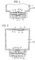
- FIG. 1 is a cross-sectional view of an ink tankcartridge constructed in accordance with a first embodiment ofthe invention;
- FIGS. 2A and 2B respectively are fragmentary cross-sectionalviews of the ink tank cartridge of FIG. 1 showing howthe membrane valve seat and the valve body operate when the inkcartridge is mounted on a recording head;
- FIG. 2C is a cross-sectional view of the ink tankcartridge of FIG. 1 showing the valve body when the inkcartridge is supplied with ink;
- FIG. 3 is a graph representing the relationshipbetween a discharging amount of ink and the fluid pressurevalue of the ink cartridge of FIG. 1;
- FIG. 4 is a fragmentary cross-sectional view of anink tank cartridge constructed in accordance with a secondembodiment of the invention showing the ink supply chamber andits surroundings;
- FIG. 5 is a cross-sectional view of an ink tankcartridge constructed in accordance with a third embodiment ofthe invention;
- FIGS. 6A and 6B respectively are fragmentary cross-sectionalviews of the ink tank cartridge of FIG. 5 showing howthe membrane valve seat and the valve body operate when the inkcartridge is mounted on a recording head;
- FIG. 6C is also a cross-sectional view of the inktank cartridge of FIG. 5 showing the valve body when the inkcartridge is supplied with ink;
- FIG. 7 is a fragmentary cross-sectional view of anink tank cartridge constructed in accordance with a fourthembodiment of the invention showing the ink supply chamber andits surroundings;
- FIG. 8 is a fragmentary cross-sectional view of anink tank cartridge constructed in accordance with a fifthembodiment of the invention showing the ink supply chamber andits surroundings;
- FIG. 9 is a fragmentary cross-sectional view of anink tank cartridge constructed in accordance with a sixthembodiment of the invention showing the ink supply chamber andits surroundings;
- FIG. 10 is a fragmentary cross-sectional view of anink tank cartridge constructed in accordance with a seventhembodiment of the invention showing the ink supply chamber andits surroundings;
- FIG. 11 is a cross-sectional view showing an inksupply port of an ink cartridge constructed in accordance withan eighth embodiment of the invention; and
- FIGS. 12A and 12B are cross-sectional views showingan ink supply port of an ink cartridge constructed inaccordance with a ninth embodiment of the invention, FIG. 12Ashowing the ink supply port not mounted on a recording head andFIG. 12B showing the ink supply port mounted on a recordinghead.
- FIG. 13 is a schematic view showing an ink supplysystem, which is an essential part of the ink jet typerecording apparatus according to the embodiments of the presentinvention.
- Fig. 13 is a schematic view showing an ink supplysystem of an ink-jet type recording apparatus to which thepresent invention can be applied.
- A
print head unit 101 of an ink-jet type is connectedto anink tank 103 through a connectingmember 102. Ink issupplied from theink tank 103 to theprint head unit 101through ahollow needle 102a and anink supply passage 102b ofthe connectingmember 102, so that theprint head unit 101emits ink droplets in accordance with print signals. - The apparatus shown in Fig. 13 also includes a
capmember 104 disposed at non-printing area, which cap membercomes into abutment against the nozzle plate of theprint headunit 101 by a drive mechanism (not shown) for preventing thenozzle openings from drying. Thecap member 104 is connectedthrough atube 108 to asuction pump 105 which is operated by acontrol device 106 to suck ink from theprint head unit 101through thecap member 104. The apparatus shown in Fig. 13 isalso provided with aneffluent tank 107 connected to an outletport of thesuction pump 105 through atube 109. - The recording head may be of any structure such asdescribed in European Patent Publication Nos. 581,531, 609,863,584,823 and so on.
- Referring to FIG. 1, a first embodiment of theinvention is depicted wherein a container constituting an inkcartridge body, indicated generally at
reference numeral 1 isformed with afirst wall 1a with anink supply port 2 formedtherein, into which an ink supply needle of a recording head(not shown) may be inserted. The space insidecontainer 1 isseparated into anink chamber 4 and anink supply chamber 5 byamembrane valve seat 3, described hereinafter.Membrane valveseat 3 is made of an elastic membrane, such as a rubbermembrane, polymeric elastomer membrane or the like, having aresistance to ink, and formed with a membrane throughhole 6 ina central portion thereof.Membrane valve seat 3 is placed ona step 7 formed in a lower portion ofcontainer 1.Membranevalve seat 3 is maintained in a stretched state by avalveassembly 9 which engages and holds the periphery ofmembranevalve seat 3 against step 7. - A
valve body 8 is vertically movably inserted into avalve throughhole 10 formed throughvalve assembly 9.Valvebody 8 has a width that ensures the formation of a gap betweenvalve assembly 9 andvalve body 8 through which ink flows, anda length slightly larger than the thickness ofvalve assembly 9. In a normal state, whencartridge 1 is not connected to arecording head undergoing a printing operation,valve body 8has its lower end placed in elastic contact withmembrane valveseat 3 by a valvebody support member 11 so as to close themembrane throughhole 6 ofmembrane valve seat 3. The lowerend ofvalve body 8 is formed with a curved periphery to form abetter seal withmembrane valve seat 3.Valve assembly 9 isformed with anink passage 15 in the surface thereof facingaway fromink supply port 2 and communicating to valve throughhole 10 for directing ink thereto. - Valve
body support member 11 is arranged on andsecured at its periphery to the surface ofvalve assembly 9 on the opposed side ofvalve assembly 9 tomembrane valve seat 3,in a stretched state in order to maintainvalve body 8 inelastic contact withmembrane valve seat 3, as well as topreventvalve body 8 from lowering below a predeterminedposition. Valvebody support member 11 is made of a similarmaterial to that ofmembrane valve seat 3, and is formed with asupport member throughhole 12 therein formingink passage 15.Also, valvebody support member 11 supports atop portion 8a ofvalve body 8 adjacent but spaced from support member throughhole 12. In this embodiment, the upper end ofvalve body 8 isformed with annularperipheral groove 8b for receiving theperiphery of a mountingaperture 11a invalve support member 11and ahead 8a shaped both to be forced through mountingaperture 11a by elastic deformation thereof due to its roundedtop end, and to retain the valve body on the valve body supportmembrane when mounted thereon. - Preferably,
membrane valve seat 3, valvebody supportmember 11, andvalve body 8 are assembled with and fixed tovalve assembly 9 prior to the final construction ofcontainer 1, and are incorporated intocontainer 1 by placing the entireassembly on step 7 ofcontainer 1 at one time. Container 1 has its upper end closed by alid member 13 having anatmosphere communicating hole 14 formedtherethrough. On the side oflid member 13 facing the insideofink chamber 4,lid member 13 is formed with arecess 30surroundingatmosphere communicating hole 14, a communicatingport 32 positioned a predetermined distance away fromrecess 30, and anarrow groove 31 constituting a capillary channel formaintainingrecess 30 and communicatingport 32 in fluidcommunication. Aflexible membrane 33 is arranged overrecess 30 andgroove 31 in such a loose state thatflexible membrane 33 is maintained a small distance away from communicatinghole 14 whenlid member 13 is placed oncontainer 1, while one wallof the capillary channel ofgroove 31 is defined byflexiblemembrane 33.- In this embodiment, if
container 1 is positioned (forexample, tilted or turned upside down) to bring ink ininkchamber 4 into contact withlid member 13,flexible membrane 33receives the pressure of the ink and is moved towardslidmember 13.Flexible membrane 33 then comes into contact with aprotrusion 14a defined byrecess 30 aroundatmospherecommunicating hole 14, so thatatmosphere communicating hole 14is closed to prevent the ink from leaking therethrough. - When
ink supply port 2 is penetrated by an ink supplyneedle of the recording head (not shown) carried on a carriage(the ink supply port being normally sealed by an inkimpermeable closure (not shown) pierceable by the needle in aconventional manner),ink supply chamber 5 is placed in fluidcommunication via this ink supply needle with the recordinghead. In this state,flexible membrane 33 oflid member 13 ismaintained in a hanging position away fromlid member 13 so asto openatmosphere communication hole 14 because of gravity orother pressure difference. Thus,ink chamber 4 communicateswith the atmosphere through openatmosphere communicating hole 14,recess 30,groove 31, and communicatingport 32. - As is shown in FIGS. 2A, 2B and 2C, in the cartridgeconstructed in this manner, when printing is started and therecording head discharges ink droplets onto a recording mediumor the like, ink in
ink supply chamber 5 flows throughinksupply port 2 into the recording head, whereby the pressureinsideink supply chamber 5 gradually decreases. In responseto the decreased pressure insideink supply chamber 5,membranevalve seat 3 receives pressure fromink chamber 4 and expandsin the direction towardink supply port 2, by virtue of itselasticity, in the form of an essentially spherical surfacehaving a radius R. At this time, sincevalve body 8 moves inconjunction with membrane valve seat 3 (FIG. 2A), ink containedinink chamber 4 is prohibited from flowing intoink supplychamber 5 which in turn prevents the pressure insideink supplychamber 5 from increasing excessively, while also preventingthe pressure insideink supply chamber 5 from decreasing excessively. In this manner, the pressure on the recordinghead is maintained at constant negative pressure with respectto theink chamber 4. - As more ink is consumed by the recording head duringa printing operation,
membrane valve seat 3 is furtherelastically expanded towardink supply port 2.Valve body 8 isprevented from lowering below a predetermined position by valvebody support member 11, so thatvalve body 8 is separated frommembrane valve seat 3 by a verynarrow gap 6a (FIG. 2B). Inthis state, ink inink chamber 4 passes through support throughhole 12,passage 15, valve throughhole 10 andnarrow gap 6aformed betweenvalve body 8 andmembrane valve seat 3, andflows through membrane throughhole 6 intoink supply chamber 5. - When the inflow of the ink causes the pressure inside
ink supply chamber 5 to slightly increase,membrane valve seat 3 moves back towardvalve body 8 by its elasticity andelastically contacts withvalve body 8, wherebynarrow gap 6aand membrane throughhole 6 are closed by the lower surface ofvalve body 8. This prohibits ink from flowing fromink chamber 4 intoink supply chamber 5. As a result, the pressure at theink supply port is maintained at a constant level irrespectiveof the amount of ink contained inink chamber 4. - Each time the pressure inside
ink supply chamber 5slightly decreases because of ink consumption during a printingoperation,membrane valve seat 3 slightly expands towardinksupply port 2 to form a gap betweenmembrane valve seat 3 andvalve body 8, through which ink fromink chamber 4 flows intoink supply chamber 5. In this manner,membrane valve seat 3,made of an elastic membrane, is brought into contact with andseparated fromvalve body 8 in accordance with the consumptionof ink during printing. Thus, by setting the elasticity ofmembrane valve seat 3 at an appropriate predeterminedmagnitude, it is possible to remarkably reduce the differencein pressure between the time an ink supply procedure will begin and end, as well as to discharge all ink inink chamber 4 tothe recording head so that none of the ink will be wasted. - If the ambient temperature rises while printing isnot being performed, the pressure inside
ink supply chamber 5will increase. This increase in pressure may also be caused bychanges in a number of other environmental factors . Inresponse to this increased pressure,membrane valve seat 3moves towardink chamber 4 which is open to the atmosphere.This prevents the pressure insideink supply chamber 5 fromincreasing, thus maintaining appropriate negative pressurebetweenink chamber 4 and recording head irrespective oftemperature rise or pressure increase. It is thereforepossible to prevent ink from leaking from the recording headdue to an increase in pressure. - In a preferred embodiment,
membrane valve seat 3 isformed of a rubber membrane having a thickness of 0.04 mm andan effective diameter, i.e., an elastically deformable regionof 20 mm. A lower limit position ofvalve body 8 is designedsuch that the radius R of the spherical surface is 26 mmimmediately before ink flows out, i.e., in a critical statewithvalve body 8. Reference is now made to FIG. 3, which is agraph which depicts the change in fluid pressure value of theink cartridge according to the invention. It can be understoodfrom FIG. 3 that even if a large amount of ink, for example,five grams per minute of ink, is supplied, the increase influid pressure value is small. Thus, ink can be smoothlysupplied to the recording head even if a large amount of ink isconsumed by the recording head without imparting excessivenegative pressure on the recording head. - During the manufacturing and ink filling process, anegative pressure is applied to
ink chamber 4 to exhaust airfromcartridge 1. Withink supply port 2 being closed by afillingseal 16,ink chamber 4 initially achieves a lowerpressure thanink supply chamber 5. Thus, as shown in FIG. 2C,valve body 8 moves towardink chamber 4 against the elasticforce of valvebody support member 11 to form afilling gap 12a betweenmembrane valve seat 3 andvalve body 8, so that all aircan be exhausted from theentire cartridge 1 includinginkchamber 4 andink supply chamber 5, irrespective of theexistence ofmembrane valve seat 3 andvalve body 8. Thispermits theentire cartridge 1, includingink supply chamber 5,to be filled with ink. - Reference is now made to FIG. 4 which depicts an
inkcartridge 200 constructed in accordance with a secondembodiment of the invention, like elements being designated bylike refe=ence numerals. In this second embodiment,valve body 8 is provided with aflat positioning piece 35 fixed thereto onthe side thereof facing valvebody support member 11, in theregion of valve throughhole 10, which abuts the upperperipheral surface ofvalve body 8 when the lower surface ofvalve body 8 is brought into contact withmembrane valve seat 3. Whenvalve body 8 abutsmembrane valve seat 3,positioningpiece 35 is maintained in contact with the upper surface ofvalve assembly 9 and the periphery ofvalve body 8, andvalvebody 8 is supported byvalve assembly 9 to maintain its postureas vertical as possible. Thus, membrane throughhole 6 ofmembrane valve seat 3 can be reliably closed byvalve body 8even ifcartridge 200 suffers from vibrations due to themovement of the carriage or the like. - Reference is now made to FIG. 5 which depicts an
inkcartridge 300 constructed in accordance with a third embodimentof the invention, like elements being designated by likereference numerals. In this embodiment avalve body 20 isinserted into a valvebody accommodating chamber 9a formed invalve assembly 9' withspring 21 positioned to urgevalve body 20 towardink supply port 2. A lower limit position ofvalvebody 20 is defined by a laterally outwardly extendingpositioning piece 36 formed on the upper end ofvalve body 20abutting a laterally inwardly extendingprotrusion 9b formed ina lower portion of valvebody accommodating chamber 9a. Also,as is shown in FIG. 5,ink chamber 4 is selectively maintainedin fluid communication withink supply chamber 5 via throughholes hole 22 communicating directly betweenink chamber 4 and valvebody accommodating chamber 9a, whichthroughhole 23 communicates directly betweenink chamber 4 andthe space betweenmembrane valve seat 3 and has a laterallyextendingsurface groove 23a formed on the side of valveassembly 9' facing saidmembrane valve seat 3 extending betweenthroughhole 23 and valvebody accommodating chamber 9a. - In this third embodiment, as is shown in FIGS. 6A, 6Band 6C,
membrane valve seat 3, in response to decreasedpressure insideink supply chamber 5, receives pressure fromink chamber 4 and expands towardsupply port 2, by virtue ofits elasticity, in the form of an essentially spherical surfacehaving a radius R. Thus, sincevalve body 20 moves inconjunction withmembrane valve seat 3 by the resilient forceofspring 21, andpositioning piece 36 abutsprotrusion 9b tomaintainvalve body 20 in a vertical posture (FIG. 6A), ink isprohibited from flowing fromink chamber 4 intoink supplychamber 5 while preventing the pressure insideink supplychamber 5 from decreasing excessively. In this manner,membrane valve seat 3 abutsvalve body 20 irrespective of anyvibrations or swinging motion of the cartridge due to themovement of the carriage, so that ink pressure on the recordinghead is maintained at constant negative pressure with respecttoink chamber 4. - As more ink is consumed by the recording head duringa printing operation,
membrane valve seat 3 is further expandedtowardink supply port 2.Valve body 20 is prevented fromlowering below a predetermined position byprotrusion 9b ofvalve accommodating chamber 9a, so thatvalve body 8 isseparated frommembrane valve seat 3 by verynarrow gap 6a(FIG. 6B). In this state, ink inink chamber 4 passes throughnarrow gap 6a formed betweenvalve body 20 andmembrane valveseat 3 and flows through membrane throughhole 6 intoinksupply chamber 5. - When the inflow of the ink causes the pressure inside
ink supply chamber 5 to slightly increase,membrane valve seat 3 moves back towardvalve body 20 by its elasticity andelastically contacts withvalve body 20, wherebynarrow gap 6aand membrane throughhole 6 are closed by the lower surface ofvalve body 20. This prohibits ink from flowing frominkchamber 4 intoink supply chamber 5. As a result, the pressureatink supply port 2 is maintained at a constant levelirrespective of the amount of ink contained in theink chamber 4. - During the manufacturing and ink filling process, anegative pressure is applied to
ink chamber 4 to exhaust airfromcartridge 300. Withink supply port 2 being closed byfillingseal 16,ink chamber 4 achieves a lower pressure thanink supply chamber 5. Thus, as shown in FIG. 6C,valve body 20moves towardink chamber 4 against force ofspring 21 to form afilling gap 12a betweenmembrane valve seat 3 andvalve body 20, so that all air can be exhausted from theentire cartridge 300, irrespective of the existence ofmembrane valve seat 3 andvalve body 20. This permits theentire cartridge 300 includingink supply chamber 5 to be filled with ink. - In the foregoing third embodiment, an elastic member(spring 21) for bringing
valve body 20 into contact withmembrane valve seat 3 is incorporated in valve assembly 9'.Alternatively, in a fourth embodiment, like elements beingdesignated by like reference numerals, anink cartridge body 400 may be formed with avalve body 37, as shown in FIG. 7,which may be formed in a mushroom shape, such that acapportion 37a functions as a positioning piece and as a stopper,and aspring 38, mounted at its periphery to the top surface ofvalve assembly 9", may be used to urge the top ofvalve body 37towardmembrane valve seat 3. Sincevalve body 37 andspring 38 can be mounted from the outside ofvalve assembly 9", theassembling work of the ink tank cartridge can be simplified. Athroughhole 9c is formed invalve assembly 9" communicatingbetweenink chamber 4 and the space between the lower surfaceofvalve assembly 9" andmembrane valve seat 3. - Reference is now made to FIG. 8 which depicts an
inkcartridge 500 constructed in accordance with a fifth embodimentof the invention, like elements being designated by likereference numerals. While in the foregoing embodiments, thespring is arranged above the valve body, it is apparent thatsimilar effects can be produced whenink cartridge 500 isseparated into anink chamber 42 and anink supply chamber 43by apartition 41 formed with a partition throughhole 41a.Ink supply chamber 43 houses amembrane valve seat 44 and avalve body 46 comprising anelongated portion 46b extendingthrough a membrane throughhole 45 and head portion having aspherically formedlower surface 46a for sealing membranethroughhole 45 formed throughmembrane valve seat 44.Elongated portion 46b extends from and perpendicular tolowersurface 46a and penetrating membrane throughhole 45 ofmembrane valve seat 44.Elongated portion 46b extends throughand is supported on aspring 47 which always urgeselongatedportion 46b, and thereforevalve body 46, in the direction ofanink supply port 49 and aguide hole 48, which receives thelower end ofsupport member 46b to positionvalve body 46 in avertical posture formed in a wall of the cartridge as shown inFIG. 8.Guide hole 48 is defined by an upwardly projectingannular wall 43a formed in abottom wall 49a ofink cartridge 500. - According to this fifth embodiment, since
valve body 46 is always urged towardwall 49a, in whichink supply port 49is formed, byspring 47 to maintain a stable posture,irrespective of any force generated by ink, ink can be stablysupplied to the recording head irrespective of any vibrationsor swinging motion of ink incartridge 500 due to the movementof the carriage. In this embodiment, similar to thosedescribed above, when the pressure belowmembrane valve seat 44is decreased due to ink being consumed during printing,membrane valve seat 44 moves towardink supply port 49, therebymaintaining the pressure belowvalve seat 44. Whenelongatedportion 46b engages the bottom ofguide hole 48, the movement ofvalve body 46 is stopped. Thereafter, any additionalconsumption of ink movesmembrane valve seat 44 away fromlowersurface 46a ofsupport member 46, thereby exposing a membranethroughhole 45, and allowing ink to pass therethrough. - Reference is now made to FIG. 9 which depicts
inkcartridge 600 constructed in accordance with a sixth embodimentof the invention, like elements being designated by likereference numerals. Alevel stabilizing membrane 50 is made ofa soft porous membrane or lattice membrane which can move inconjunction withmembrane valve seat 3 is provided. A porousmember through hole 51 is formed through a regionoppositevalve body 8 of stabilizingmembrane 50, and a lower endportion ofvalve body 8 is fit into porous member through hole51. Stabilizingmembrane 50 has its periphery secured tovalveassembly 9 and a central portion thereof secured tovalve body 8. - When the pressure inside
ink supply chamber 5decreases as more ink is consumed during a printing operation,membrane valve seat 3 separates fromvalve body 8 so that inkinink chamber 4 flows through porous member through hole 51 oflevel stabilizing membrane 50 intoink supply chamber 5. - After an additional amount of ink has been consumedduring printing operations and the level of ink in
ink chamber 4 has been reduced to a level lower than the position ofvalveassembly 9, the ink inink chamber 4 may violently swing nearvalve body 8 due to the movement of the carriage. However,since the ink passes through membrane throughhole 6 ofmembrane valve seat 3 after fluctuations in pressure of the inkhave been suppressed bylevel stabilizing membrane 50 as muchas possible, the ink pressure on the recording head ismaintained at a constant level irrespective of the amount ofink remaining inink chamber 4. - While in a number of the foregoing embodiments, anelastic member (valve body support member 11) is used toelastically maintain contact between the
valve body 8 andmembrane valve seat 3, the elastic member for elastically contactingvalve body 8 withmembrane valve seat 3 may beunnecessary if the elastic force of membrane valve seat-3 isactively utilized. - Reference is now made to FIG. 10 which depicts an
inkcartridge 700 constructed in accordance with a seventhembodiment of the invention, like elements being'designed bylike reference numerals. This seventh embodiment does notrequire an elastic member for elastically urging a valve bodyto maintain contact with a membrane valve seat. As shown inFIG. 10, amembrane valve seat 24 is formed with a membranethroughhole 25 formed therein in a region opposing avalvebody 28, hereinafter described, and has its periphery securedby avalve assembly 27.Valve body 28 is unmovably fixed tovalve assembly 27 in a position perpendicular thereto.Inkchamber 4 is selectively maintained in fluid communication withink supply chamber 5 via a communicatinghole 29 in the form ofa radial slit extending fromvalve body 28. When a pressuredifference betweenink chamber 4 andink supply chamber 5 isequal to or less than a predetermined value,membrane valveseat 24, through its own elasticity, brings membrane throughhole 25 into contact withvalve body 28 to stop the outflow ofink fromink chamber 4 toink supply chamber 5. - On the other hand, if the pressure inside
ink supplychamber 5 decreases,membrane valve seat 24 extends towardinksupply port 2 in the form of a spherical surface, wherebymembrane throughhole 25 is removed from contact withvalvebody 28, and accordingly ink flows fromink chamber 4 intoinksupply chamber 5 via membrane throughhole 25. After asufficient amount of ink has been supplied toink supplychamber 5 to raise the pressure insideink supply chamber 5,membrane valve seat 24 elastically contacts withvalve body 28,against the pressure difference betweenink chamber 4 andinksupply chamber 5, to stop the outflow of ink fromink chamber 4toink supply chamber 5. - Reference is now made to FIG. 11 which depicts an inkcartridge constructed in accordance with an eighth embodiment of the invention, like elements being designated by likereference numerals. The ink cartridge of this eighthembodiment prevents air from entering a recording head at thetime the recording head has depleted all of the ink in the inkcartridge. In a connecting region between an
ink supply port 52 and anink supply chamber 53, a downwardly taperedconicalvalve seat 54 is formed. A spherical floatingvalve 55, whichfloats by a floating force produced by the buoyancy ofspherical floatingvalve 55, is accommodated inconical valvecoat 54. Further, the upper end of theconical valve seat 54is covered with avalve retention plate 56, made of an inktransmissible material such as a screen, to complete ashielding valve. In FIG. 11, amembrane valve seat 57 is alsoarranged in selectable contact with avalve body 58 forcontrolling the flow of ink thereto from an ink chamber (notshown). - When the ink cartridge is mounted on the recordinghead, floating
valve 55 floats upward and is retained againstvalve retention plate 56 by a floating force to openink supplyport 52 through which ink is supplied to the recording head.As ink in the cartridge is consumed during printing operations,the level of ink in the cartridge is reduced in the vicinity ofink supply port 52. Floatingvalve 55 looses its floatingforce because of the absence of ink, and therefore comes intocontact withvalve seat 54 to close ink supply port 52 (asindicated by the broken line in FIG. 11). Even if printing iscontinued with the almost exhausted cartridge, the closedinksupply port 52 prohibits air from entering the recording head,thus preventing defective printing. - Generally, an ink cartridge, once mounted on arecording head, is not removed until ink contained in the inkchamber is depleted. However, the ink cartridge may be removedfrom the recording head by an erroneous manipulation. If aonce mounted cartridge is removed from the recording head,
inksupply port 52 is open to the atmosphere and may allow air toenter the ink supply chamber and the ink chamber, which may adversely affect the flow of ink during the recordingoperation. - Reference is now made to FIGS. 12A and 12B whichdepict an ink tank cartridge constructed in accordance with aninth embodiment of the present invention, like elements beingdesignated by like reference numerals. As shown in FIGS. 12Aand 12B, the ink cartridge of this ninth embodiment preventsair from entering the cartridge if the ink cartridge is removedbefore it is depleted. A
telescopical valve body 60 isarranged in anink supply port 61, and is formed with an inksupply needlefitting hole 62 in its lower portion into whichanink supply needle 70 may be removably fitted.Valve body 60is also formed with a communicatinghole 64 for connecting anink supply chamber 63 with ink supply needlefitting hole 62whenvalve body 60 moves to an upward limited position. - In this embodiment, before insertion of
ink supplyneedle 70, as shown in FIG. 12A,valve body 60 which is formedwith a radially extending,elastic periphery 60a, is maintainedin elastic contact with abottom surface 63a ofink supplychamber 63 by its elasticity to reliably prevent the outflow ofink fromink supply chamber 63. - When
ink supply needle 70 is inserted intofittinghole 62,valve body 60 is separated frombottom surface 63a ofink supply chamber 63 and extends to the upward limitedposition, while communicatinghole 64 is exposed to ink supplychamber 63 (FIG. 12B). This causesink supply chamber 63 to beplaced in fluid communication with anink passage 70a ofinksupply needle 70 through communicatinghole 64, and aneedlecommunicating hole 70b, whereby ink inink supply chamber 63flows intoink supply needle 70 and is consequently supplied tothe recording head.
When the ink cartridge mounted on the recording head isremoved,valve body 60 moves toward the bottom 63A of FIG. 12Ato closeink supply port 61 and henceink supply chamber 63.This prevents the outflow of ink fromink supply chamber 63 aswell as the entrance of air intoink supply chamber 63. - According to the present invention as describedabove, a container formed with an ink supply port in one of itswalls is separated by a membrane valve seat made of an elasticthin membrane and formed with a through hole in the centralportion thereof. An ink chamber is formed in the portion ofthe cartridge not adjacent the ink supply port, and an inksupply chamber is formed in the portion of the cartridgeadjacent the ink supply port, and a valve body is positioned inopposition to the through hole. The membrane valve seatreceives a pressure difference over a large area thereofbecause of the consumption of ink and allows ink to flow fromthe ink chamber in response to a small amount of consumed ink.Thus, the recording head can be supplied with ink withoutimparting excessive negative pressure on the recording head,and ink in the ink chamber can be discharged to the recordinghead without waste. Moreover, if the ambient temperature risesgreatly or other environmental factors cause the pressure toincrease while printing is not being performed, the membranevalve body displaces toward the ink chamber to release thepressure increased by the pressure rise inside the ink supplychamber communicating with the recording head to the inkchamber. It is therefore possible to prevent ink from leakingwhen the printer is not in use. Also, when the ink cartridgeis mounted on the recording head, negative pressure suitablefor printing is maintained between the recording head and theink cartridge to ensure stable printing.
- Further, since the elasticity of the membrane valveseat ensures an airtight seal between the membrane valve seatand the valve body, the valve function can be reliablyperformed irrespective of any swinging motion or vibrations ofink in the ink chamber caused by the movement of the carriage,thus making it possible to maintain a pressure differencebetween the ink cartridge and the recording head irrespectiveof the movement of the carriage to achieve an improvement inprinting quality.
- It will thus be seen that the aspects set forthabove, and those made apparent from the preceding description,are efficiently attained and, since certain changes may be madein the above constructions without departing from thescope of the invention, it is intended that all mattercontained in the above description or shown in the accompanyingdrawings shall be interpreted as illustrative and not in alimiting sense.
- It is also to be understood that the following claimsare intended to cover all of the generic and specific featuresof the invention herein described, and all statements of thescope of the invention which, as a matter of language, might besaid to fall therebetween.
Claims (22)
- An ink cartridge (1; 200; 300; 400; 500; 600; 700) for anink jet recording apparatus, comprising: a containerhaving an ink supply port (2; 49; 52; 61) formed througha wall (la) of said container and adapted to receive anink supply needle (70) of the recording apparatustherein;
a membrane valve seat (3; 24; 44; 57) formed with athrough hole (6) therethrough; said membrane valve seat(3; 24; 44; 57) separating an ink chamber (4; 42) in afirst portion of said container from an ink supplychamber (5; 43; 53; 63) in a second portion of saidcontainer, said ink supply chamber (5; 43; 53; 63) beingin fluid communication with said ink supply port (2; 49;52; 61); and
a valve body (8; 20; 28; 37; 46; 58; 60) positionedopposing said through hole (6) formed in said membranevalve seat (3; 24; 44; 57) such that said membrane valveseat (3; 24; 44; 57) is urged against said valve body (8;20; 28; 37; 46; 58; 60);
wherein said membrane valve seat (3; 24; 44; 57) isseparable from said valve body (8; 20; 28; 37; 46; 58;60) by a pressure difference between said ink chamber (4;42) and said ink supply chamber (5; 43; 53; 63) due to aconsumption of ink by an ink jet recording head of saidink jet recording apparatus. - An ink cartridge (1; 200; 300; 400; 500; 600; 700) forproviding ink for an ink jet recording apparatus andproviding a valve function for maintaining a negativepressure suitable for printing, said ink cartridge (1;200; 300; 400; 500; 600; 700) comprising:a container having an ink supply port (2; 49; 52; 61)formed through a wall (la) of said container and adaptedto receive an ink supply needle (70) of the recordingapparatus therein;a membrane valve seat (3; 24; 44; 57) formed with athrough hole (6) therethrough; said membrane valve seat(3; 24; 44; 57) separating an ink chamber (4; 42) in afirst portion of said container from an ink supplychamber (5; 43; 53; 63) in a second portion of saidcontainer, said ink supply chamber (5; 43; 53; 63) beingin fluid communication with said ink supply port (2; 49;52; 61); anda valve body (8; 20; 28; 37; 46; 58; 60) positionedopposing said through hole (6) formed in said membranevalve seat (3; 24; 44; 57) such that said membrane valveseat (3; 24; 44; 57) is urged against said valve body (8;20; 28; 37; 46; 58; 60).
- The ink cartridge (1; 200; 300; 400; 500; 600; 700)according to claim 1 or 2, wherein said membrane valveseat (3; 24; 44; 57) is separable from said valve body(8; 20; 28; 37; 46; 58; 60) to open a passage from saidink chamber (4; 42) to said ink supply chamber (5; 43;53; 63) through said through hole (6) of said membranevalve seat (3; 24; 44; 57).
- The ink cartridge (1; 200; 300; 400; 500; 600; 700)according to one of claims 1 to 3, wherein said membrane valve seat (3; 24; 44; 57) is movable with respect tosaid container.
- The ink cartridge (700) according to one of claims 1 to4, wherein said valve body (28) is unmovably fixed withrespect to said container.
- The ink cartridge (500; 700) according to one of claims 1to 5, further comprising a valve assembly including apartition wall (27; 41) having a surface facing saidmembrane valve seat (24; 44) and wherein said ink chamber(42) includes an ink volume defined between saidpartition wall (27; 41) and said membrane valve seat (24;44).
- The ink cartridge (700) according to claim 6, whereinsaid valve body (28) is provided by said partition wall(27).
- The ink cartridge (700) according to claim 6 or 7,wherein said wall (27; 41) comprises a communicating hole(29; 41a) for communicating said ink volume with a mainportion of said ink chamber (4; 42).
- The ink cartridge (700) according to claim 8, whereinsaid communicating hole (29; 41a) is laterally displacedin said wall and with respect to said through hole (6) insaid membrane valve seat (24; 44).
- The ink cartridge (1; 200; 300; 400; 500; 600; 700)according to one of claims 1 to 9, wherein said membranevalve seat (3; 24; 44; 57) separates from said valve body(8; 20; 28; 37; 46; 58; 60) when the pressure inside saidink supply chamber (5; 43; 53; 63) is a predeterminedvalue or lower than the pressure inside said ink chamber(4; 42).
- The ink cartridge (1; 200; 300; 400; 500; 600; 700)according to one of claims 1 to 10, wherein said throughhole (6) is positioned in a central portion of saidmembrane valve seat (3; 24; 44; 57) and being expandablesubstantially in the form of a spherical surfaceprotruding when said pressure inside said ink supplychamber (5; 43; 53; 63) is a predetermined value or lowerthan the pressure inside said ink chamber (4; 42).
- The ink cartridge (1; 200; 300; 400; 500; 600; 700)according to one of claims 1 to 11, wherein said valvebody (8; 20; 28; 37; 46; 58; 60) and said membrane valveseat (3; 24; 44; 57) are elastically urged against eachother by an urging member (21; 38; 47).
- The ink cartridge (300; 400; 500) of claim 12, whereinsaid urging member is a spring (21; 38; 47).
- The ink cartridge (500) of claim 12 or 13, wherein saidurging member is an elastic membrane (47).
- The ink cartridge (200; 300; 400) according to one ofclaims 1 to 14, further comprising a retaining member(35; 36; 37a) for limiting the movement of said valvebody (8; 20; 37) to a predetermined distance.
- The ink cartridge (200; 300; 400; 500) according to oneof claims 1 to 15, further comprising a positioning piece(35; 36; 37a; 46b) for positioning said valve body (8;20; 37; 46) essentially perpendicularly to said membranevalve seat (3; 44) at said through hole (6).
- The ink cartridge (600) according to one of claims 1 to16, further comprising a level stabilizing membrane (50)made of an ink transmissible material which moves in conjunction with said membrane valve seat (3), said valvebody (8) extending therethrough.
- The ink cartridge (600) according to claim 17, whereinsaid valve body (8) is secured to said level stabilizingmembrane (50).
- The ink cartridge (1; 200; 300; 400; 500; 600; 700)according to one of claims 1 to 18, wherein said membranevalve seat (3; 24; 44; 57) is made of an elastic thinmembrane.
- The ink cartridge (1; 200; 300; 400; 500; 600; 700)according to claim 19, wherein said elastic thin membraneis formed as a rubber membrane or a polymeric elastomermembrane.
- The ink cartridge (1; 200; 300; 400; 500; 600; 700)according to one of claims 1 to 20, wherein said throughhole (6) is positioned in a central portion of saidmembrane valve seat (3; 24; 44; 57).
- An ink jet recording apparatus, comprising:a print head (101) for emitting ink droplets inaccordance with print signals;an ink supply needle (70) communicating with said printhead (101); andan ink cartridge (1; 200; 300; 400; 500; 600; 700)according to one of claims 1 to 21, connecting to saidprint head (101) through said ink supply port (2; 49; 52;61) and said ink supply needle (70) detachably receivedin said ink supply port (2; 49; 52; 61).
Applications Claiming Priority (6)
| Application Number | Priority Date | Filing Date | Title |
|---|---|---|---|
| JP28729294 | 1994-10-26 | ||
| JP28729294 | 1994-10-26 | ||
| JP25810195AJPH08174860A (en) | 1994-10-26 | 1995-09-11 | Ink cartridge for inkjet printer |
| JP25810195 | 1995-09-11 | ||
| EP20000106742EP1013443B1 (en) | 1994-10-26 | 1995-10-26 | Ink cartridge for ink jet printer |
| EP19950116908EP0709207B1 (en) | 1994-10-26 | 1995-10-26 | Ink cartridge for ink jet printer |
Related Parent Applications (3)
| Application Number | Title | Priority Date | Filing Date |
|---|---|---|---|
| EP20000106742DivisionEP1013443B1 (en) | 1994-10-26 | 1995-10-26 | Ink cartridge for ink jet printer |
| EP95116908.5Division | 1995-10-26 | ||
| EP00106742.0Division | 2000-03-29 |
Publications (3)
| Publication Number | Publication Date |
|---|---|
| EP1279515A2 EP1279515A2 (en) | 2003-01-29 |
| EP1279515A3 EP1279515A3 (en) | 2003-04-02 |
| EP1279515B1true EP1279515B1 (en) | 2004-01-07 |
Family
ID=26543543
Family Applications (7)
| Application Number | Title | Priority Date | Filing Date |
|---|---|---|---|
| EP19950116908Expired - LifetimeEP0709207B1 (en) | 1994-10-26 | 1995-10-26 | Ink cartridge for ink jet printer |
| EP20000106743Expired - LifetimeEP1010536B1 (en) | 1994-10-26 | 1995-10-26 | Ink cartridge for ink jet printer |
| EP20020024287Expired - LifetimeEP1279514B1 (en) | 1994-10-26 | 1995-10-26 | Ink cartridge for ink jet printer |
| EP20000106742Expired - LifetimeEP1013443B1 (en) | 1994-10-26 | 1995-10-26 | Ink cartridge for ink jet printer |
| EP20020024288Expired - LifetimeEP1279515B1 (en) | 1994-10-26 | 1995-10-26 | Ink cartridge for ink jet printer |
| EP20020024286Expired - LifetimeEP1279513B9 (en) | 1994-10-26 | 1995-10-26 | Ink cartidge for ink jet printer |
| EP20050025214WithdrawnEP1640168A3 (en) | 1994-10-26 | 1995-10-26 | Ink cartridge for ink-jet printer |
Family Applications Before (4)
| Application Number | Title | Priority Date | Filing Date |
|---|---|---|---|
| EP19950116908Expired - LifetimeEP0709207B1 (en) | 1994-10-26 | 1995-10-26 | Ink cartridge for ink jet printer |
| EP20000106743Expired - LifetimeEP1010536B1 (en) | 1994-10-26 | 1995-10-26 | Ink cartridge for ink jet printer |
| EP20020024287Expired - LifetimeEP1279514B1 (en) | 1994-10-26 | 1995-10-26 | Ink cartridge for ink jet printer |
| EP20000106742Expired - LifetimeEP1013443B1 (en) | 1994-10-26 | 1995-10-26 | Ink cartridge for ink jet printer |
Family Applications After (2)
| Application Number | Title | Priority Date | Filing Date |
|---|---|---|---|
| EP20020024286Expired - LifetimeEP1279513B9 (en) | 1994-10-26 | 1995-10-26 | Ink cartidge for ink jet printer |
| EP20050025214WithdrawnEP1640168A3 (en) | 1994-10-26 | 1995-10-26 | Ink cartridge for ink-jet printer |
Country Status (7)
| Country | Link |
|---|---|
| US (6) | US6000788A (en) |
| EP (7) | EP0709207B1 (en) |
| JP (1) | JPH08174860A (en) |
| KR (1) | KR0167405B1 (en) |
| CN (6) | CN1057491C (en) |
| DE (6) | DE69534986T2 (en) |
| TW (1) | TW370008U (en) |
Families Citing this family (175)
| Publication number | Priority date | Publication date | Assignee | Title |
|---|---|---|---|---|
| JP3582592B2 (en)* | 2001-04-03 | 2004-10-27 | セイコーエプソン株式会社 | Ink cartridge and inkjet recording device |
| US6183076B1 (en)* | 1992-04-02 | 2001-02-06 | Hewlett-Packard Company | Printer having multi-chamber print cartridges and off-carriage regulator |
| JPH08174860A (en) | 1994-10-26 | 1996-07-09 | Seiko Epson Corp | Ink cartridge for inkjet printer |
| DE19545775C2 (en)* | 1995-12-07 | 1999-03-25 | Pelikan Produktions Ag | Liquid cartridge, in particular an ink cartridge for a print head of an ink jet printer |
| EP0827836B1 (en) | 1996-02-21 | 2005-05-04 | Seiko Epson Corporation | Ink cartridge |
| US6130694A (en)* | 1996-05-13 | 2000-10-10 | Hewlett-Packard Company | Regulator assembly for modulating fluid pressure within an ink-jet printer |
| US5988802A (en)* | 1996-08-30 | 1999-11-23 | Hewlett-Packard Company | Off-axis ink supply with pressurized ink tube for preventing air ingestion |
| KR100209516B1 (en)* | 1997-02-05 | 1999-07-15 | 윤종용 | Ink containing apparatus and method of ink jet print head |
| JP4141523B2 (en)* | 1997-03-19 | 2008-08-27 | セイコーエプソン株式会社 | Ink supply flow path valve device |
| US6692117B1 (en) | 1997-07-14 | 2004-02-17 | Owens-Illinois Closure Inc. | Liquid containment and dispensing device with improved flow control valve |
| CA2248434A1 (en)* | 1997-09-30 | 1999-03-30 | Asahi Kogaku Kogyo Kabushiki Kaisha | Ink-transfer type printer |
| JPH11157092A (en)* | 1997-11-26 | 1999-06-15 | Bridgestone Corp | Manufacture of member for ink jet printer |
| DE69911744T2 (en) | 1998-02-13 | 2004-07-29 | Seiko Epson Corp. | INK-JET PRINTER, TANK UNIT SUITABLE FOR IT AND METHOD FOR RESTORING THE INK DROPLET CAPACITY |
| SG95595A1 (en) | 1998-05-13 | 2003-04-23 | Seiko Epson Corp | Ink cartridge for ink-jet printing apparatus |
| EP2179848A1 (en) | 1998-05-18 | 2010-04-28 | Seiko Epson Corporation | Ink-jet printing apparatus and ink cartridge therefor |
| EP0965780B1 (en)* | 1998-06-16 | 2005-08-31 | Bridgestone Corporation | Fluid supply valve |
| US6550498B2 (en)* | 1998-06-16 | 2003-04-22 | Seiko Epson Corporation | Fluid supply valve |
| EP2108513B1 (en)* | 1998-07-15 | 2011-05-04 | Seiko Epson Corporation | Ink supply unit |
| US6299296B2 (en)* | 1998-07-31 | 2001-10-09 | Hewlett Packard Company | Sealing member for a fluid container |
| EP1043161B1 (en)* | 1999-04-08 | 2007-06-13 | Seiko Epson Corporation | Ink jet recording apparatus and cleaning control method for recording head incorporated therein |
| US6799820B1 (en)* | 1999-05-20 | 2004-10-05 | Seiko Epson Corporation | Liquid container having a liquid detecting device |
| JP2001199082A (en) | 1999-10-08 | 2001-07-24 | Seiko Epson Corp | INK CARTRIDGE, INK JET RECORDING DEVICE, AND METHOD OF MOUNTING INK CARTRIDGE |
| GB9925988D0 (en)* | 1999-11-03 | 2000-01-12 | Dynamic Cassette Int | An ink cartridge |
| WO2001053103A1 (en) | 2000-01-18 | 2001-07-26 | Seiko Epson Corporation | Ink cartridge, ink jet type recording device using the ink cartridge, and cleaning control method for recording head of the recording device |
| US6431697B1 (en)* | 2000-01-31 | 2002-08-13 | Hewlett-Packard Company | Replaceable ink container having a separately attachable latch and method for assembling the container |
| CN1280103C (en) | 2000-02-16 | 2006-10-18 | 精工爱普生株式会社 | Cartriage and connecting assembly for ink-jet printer and ink-jet printer |
| US20030107626A1 (en)* | 2000-08-16 | 2003-06-12 | Xiao Qingguo | Ink cartridge having bellows valve, ink filling method and apparatus used thereof |
| US6935730B2 (en)* | 2000-04-03 | 2005-08-30 | Unicorn Image Products Co. Ltd. Of Zhuhai | One-way valve, valve unit assembly, and ink cartridge using the same |
| MXPA02009735A (en)* | 2000-04-03 | 2003-03-27 | Unicorn Image Products Co Ltd | An ink cartridge and a method and device for filling the ink cartridge. |
| JP2002001988A (en)* | 2000-04-18 | 2002-01-08 | Canon Aptex Inc | Ink tank and ink jet cartridge |
| US6837575B2 (en)* | 2000-07-07 | 2005-01-04 | Seiko Epson Corporation | Ink feed unit for ink jet recorder and diaphragm valve |
| US20050243147A1 (en)* | 2000-10-12 | 2005-11-03 | Unicorn Image Products Co. Ltd. | Ink cartridge having bellows valve, ink filling method and apparatus used thereof |
| CA2469450C (en)* | 2000-10-20 | 2010-02-23 | Seiko Epson Corporation | Ink cartridge for ink jet recording device |
| PT1199179E (en) | 2000-10-20 | 2007-02-28 | Seiko Epson Kabushiki Kaisha S | Ink-jet recording device and ink cartridge |
| SG103840A1 (en)* | 2000-10-20 | 2004-05-26 | Seiko Epson Corp | Ink-jet recording device and ink cartridge |
| GB2368557A (en)* | 2000-11-03 | 2002-05-08 | Opportunity Europ Limimted | Ink cartridge including a float valve disposed in the ink outlet chamber thereof |
| JP4635330B2 (en)* | 2000-12-07 | 2011-02-23 | ブラザー工業株式会社 | Inkjet printer |
| JP4673983B2 (en)* | 2001-01-31 | 2011-04-20 | 株式会社ブリヂストン | Elastic member for ink jet recording apparatus, ink tank, and ink jet recording apparatus |
| JP4673982B2 (en)* | 2001-01-31 | 2011-04-20 | 株式会社ブリヂストン | Elastic member for ink jet recording apparatus, ink tank, and ink jet recording apparatus |
| JP4673992B2 (en)* | 2001-04-02 | 2011-04-20 | 株式会社ブリヂストン | Elastic member for ink jet recording apparatus, ink tank, and ink jet recording apparatus |
| WO2002060697A1 (en)* | 2001-01-31 | 2002-08-08 | Bridgestone Corporation | Elastic members for inkjet recording apparatus, ink tanks and inkjet recording apparatus |
| WO2002061308A1 (en) | 2001-01-31 | 2002-08-08 | Bridgestone Corporation | Cover-integrated gasket |
| JP4193435B2 (en)* | 2002-07-23 | 2008-12-10 | ブラザー工業株式会社 | Ink cartridge and ink filling method thereof |
| CN2649337Y (en)* | 2001-05-17 | 2004-10-20 | 精工爱普生株式会社 | Ink cartridge |
| CN1193887C (en)* | 2001-05-17 | 2005-03-23 | 精工爱普生株式会社 | Ink cartridge and air pressure opening valve assembly method in the ink cartridge |
| MY128925A (en)* | 2001-05-17 | 2007-02-28 | Seiko Epson Corp | Ink cartridge |
| CN100393521C (en) | 2001-05-17 | 2008-06-11 | 精工爱普生株式会社 | Method for injecting ink into ink box |
| US6477956B1 (en)* | 2001-08-10 | 2002-11-12 | Sonoco Development, Inc. | Ink cartridge with self-closing valve |
| DE10141817B4 (en)* | 2001-08-27 | 2005-03-03 | Eppendorf Ag | Membrane device for receiving samples and method for producing a device |
| WO2003037634A1 (en)* | 2001-10-31 | 2003-05-08 | Print-Rite Unicorn Image Products Co. Ltd Of Zhuhai | An ink cartridge for a printer |
| US7029104B2 (en) | 2001-11-08 | 2006-04-18 | Seiko Epson Corporation | Ink cartridge and recording apparatus |
| US7086722B2 (en)* | 2001-11-12 | 2006-08-08 | Seiko Epson Corporation | Ink cartridge |
| WO2003041964A1 (en) | 2001-11-12 | 2003-05-22 | Seiko Epson Corporation | Liquid injector |
| CN2544940Y (en)* | 2002-04-27 | 2003-04-16 | 珠海纳思达电子科技有限公司 | Ink cartridge of printer |
| JP3901019B2 (en) | 2002-06-04 | 2007-04-04 | ブラザー工業株式会社 | ink cartridge |
| JP3891150B2 (en)* | 2002-07-09 | 2007-03-14 | セイコーエプソン株式会社 | Liquid cartridge and liquid container |
| USD497635S1 (en) | 2002-09-10 | 2004-10-26 | Ricoh Company, Ltd. | Printer ink cartridge |
| RU2259924C2 (en)* | 2002-09-12 | 2005-09-10 | Сейко Эпсон Корпорейшн | Ink cartridge (variants), device and method for adjusting flow of liquid from cartridge |
| JP3991853B2 (en)* | 2002-09-12 | 2007-10-17 | セイコーエプソン株式会社 | ink cartridge |
| US6984030B2 (en) | 2002-11-13 | 2006-01-10 | Seiko Epson Corporation | Ink cartridge and method of regulating fluid flow |
| GB0226708D0 (en)* | 2002-11-15 | 2002-12-24 | Avecia Ltd | Compounds |
| CN1277685C (en)* | 2002-12-10 | 2006-10-04 | 精工爱普生株式会社 | liquid box |
| CN2614901Y (en)* | 2003-01-14 | 2004-05-12 | 珠海天威飞马打印耗材有限公司 | Sealing ring, ink cartridge |
| US6951387B2 (en)* | 2003-01-15 | 2005-10-04 | Xerox Corporation | Ink tank with capillary member |
| US6877849B2 (en)* | 2003-01-23 | 2005-04-12 | Hewlett-Packard Development Company, L.P. | Printing system with high volumetric ink container vessel |
| US8454135B2 (en) | 2003-02-04 | 2013-06-04 | Brother Kogyo Kabushiki Kaisha | Air bubble removal in an ink jet printer |
| EP1590181B1 (en)* | 2003-02-04 | 2007-04-04 | Brother Kogyo Kabushiki Kaisha | Air bubble removal in an ink jet printer |
| CN100351090C (en)* | 2003-03-05 | 2007-11-28 | 精工爱普生株式会社 | Liquid container, member for forming a liquid container and method of manufacturing a liquid container |
| JP3873910B2 (en)* | 2003-03-05 | 2007-01-31 | セイコーエプソン株式会社 | Liquid storage bag and liquid ejection device |
| EP1468748A1 (en)* | 2003-04-15 | 2004-10-20 | Microflow Engineering SA | Low-cost liquid droplet spray device and nozzle body |
| JP3848298B2 (en) | 2003-05-22 | 2006-11-22 | キヤノン株式会社 | Ink tank |
| US7401367B2 (en)* | 2003-05-28 | 2008-07-22 | Graco Children's Products Inc. | Playard |
| US6865756B2 (en)* | 2003-05-28 | 2005-03-15 | Graco Children's Products Inc. | Playard |
| US6837577B1 (en)* | 2003-06-18 | 2005-01-04 | Lexmark International, Inc. | Ink source regulator for an inkjet printer |
| US7163282B2 (en)* | 2003-06-20 | 2007-01-16 | Seiko Epson Corporation | Valve unit and liquid ejecting apparatus |
| US7699449B2 (en)* | 2003-06-20 | 2010-04-20 | Seiko Epson Corporation | Liquid injection apparatus and method for driving the same |
| JP2005047207A (en)* | 2003-07-31 | 2005-02-24 | Shinko Electric Ind Co Ltd | Inkjet printer |
| KR20110128959A (en)* | 2003-10-01 | 2011-11-30 | 니폰 가야꾸 가부시끼가이샤 | Azo compounds, aqueous dye solutions containing them, inks and uses thereof |
| US7159974B2 (en)* | 2003-10-06 | 2007-01-09 | Lexmark International, Inc. | Semipermeable membrane for an ink reservoir and method of attaching the same |
| US20050095139A1 (en)* | 2003-10-30 | 2005-05-05 | A.O. Smith Corporation | Apparatus and method for containing and regulating the pressure in a pressure vessel |
| US7278722B2 (en)* | 2003-11-25 | 2007-10-09 | Brother Kogyo Kabushiki Kaisha | Ink cartridge |
| JP2005186344A (en)* | 2003-12-24 | 2005-07-14 | Seiko Epson Corp | Valve device and liquid injection device |
| JP4525080B2 (en)* | 2004-01-14 | 2010-08-18 | セイコーエプソン株式会社 | Liquid filling method for liquid container |
| US20050157112A1 (en) | 2004-01-21 | 2005-07-21 | Silverbrook Research Pty Ltd | Inkjet printer cradle with shaped recess for receiving a printer cartridge |
| US7448734B2 (en)* | 2004-01-21 | 2008-11-11 | Silverbrook Research Pty Ltd | Inkjet printer cartridge with pagewidth printhead |
| US7188937B2 (en)* | 2004-01-29 | 2007-03-13 | Hewlett-Packard Development Company, L.P. | Printing-fluid venting assembly |
| ATE488372T1 (en)* | 2004-02-09 | 2010-12-15 | Brother Ind Ltd | INK CARTRIDGE |
| JP4746843B2 (en)* | 2004-03-15 | 2011-08-10 | ブラザー工業株式会社 | Ink cartridge and ink jet recording apparatus |
| US20050219281A1 (en) | 2004-03-24 | 2005-10-06 | Takeo Seino | Attachment and liquid supplying |
| JP4731136B2 (en)* | 2004-07-05 | 2011-07-20 | 株式会社ニックス | Liquid sending and receiving joint device |
| US7431435B2 (en)* | 2004-08-06 | 2008-10-07 | Matthew Grant Lopez | Systems and methods for varying dye concentrations |
| JP4742735B2 (en)* | 2004-09-24 | 2011-08-10 | セイコーエプソン株式会社 | Liquid ejector |
| JP4258462B2 (en)* | 2004-11-19 | 2009-04-30 | セイコーエプソン株式会社 | Pressure regulating valve, functional liquid supply device and drawing device |
| US20060203048A1 (en)* | 2005-03-14 | 2006-09-14 | Scheffelin Joseph E | Plug |
| JP4725265B2 (en)* | 2005-03-31 | 2011-07-13 | ブラザー工業株式会社 | Inkjet recording device |
| CN100467277C (en)* | 2005-03-31 | 2009-03-11 | 精工爱普生株式会社 | Liquid container and liquid filling method |
| JP4725182B2 (en)* | 2005-04-28 | 2011-07-13 | セイコーエプソン株式会社 | Method for manufacturing liquid supply system and liquid supply system |
| CN2920655Y (en)* | 2005-06-10 | 2007-07-11 | 珠海纳思达电子科技有限公司 | Universal printer ink cartridge |
| CN2832528Y (en)* | 2005-08-02 | 2006-11-01 | 珠海纳思达电子科技有限公司 | Ink cartridge for ink-jet printer |
| US20070035596A1 (en)* | 2005-08-10 | 2007-02-15 | Lexmark International, Inc. | Ink jet cartridge |
| US7506958B2 (en)* | 2005-10-11 | 2009-03-24 | Silverbrook Research Pty Ltd | Printhead maintenance station |
| US7648222B2 (en)* | 2005-10-11 | 2010-01-19 | Silverbrook Research Pty Ltd | Printhead maintenance station comprising maintenance roller and ink removal system |
| US7753472B2 (en)* | 2005-10-11 | 2010-07-13 | Silverbrook Research Pty Ltd | Printhead maintenance station having rotational pad engagement |
| US7686419B2 (en)* | 2005-10-11 | 2010-03-30 | Silverbrook Research Pty Ltd | Method of maintaining a printhead using a roller action |
| US20070103520A1 (en)* | 2005-11-04 | 2007-05-10 | U Colour International Co., Ltd. | Interior pressure self-adjustable ink supply cartridge structure |
| JP2007160926A (en) | 2005-11-18 | 2007-06-28 | Seiko Epson Corp | Droplet discharge device |
| JP4994648B2 (en)* | 2005-11-30 | 2012-08-08 | キヤノン株式会社 | Ink tank and ink jet recording apparatus using the same |
| US7556364B2 (en) | 2005-12-05 | 2009-07-07 | Silverbrook Research Pty Ltd | Ink cartridge with self sealing outlet valve |
| US7357496B2 (en)* | 2005-12-05 | 2008-04-15 | Silverbrook Research Pty Ltd | Inkjet printhead assembly with resilient ink connectors |
| JP2007182055A (en) | 2005-12-06 | 2007-07-19 | Seiko Epson Corp | Liquid container |
| JP4899683B2 (en)* | 2005-12-13 | 2012-03-21 | セイコーエプソン株式会社 | Differential pressure valve unit |
| US20070170528A1 (en)* | 2006-01-20 | 2007-07-26 | Aaron Partridge | Wafer encapsulated microelectromechanical structure and method of manufacturing same |
| WO2007109990A1 (en)* | 2006-03-24 | 2007-10-04 | Print-Rite Technology Development Co., Ltd Of Zhuhai | A valve body, a valve assembly and an ink cartridge |
| DE102006026258A1 (en) | 2006-06-02 | 2007-12-06 | Artech Gmbh Design + Production In Plastic | ink cartridge |
| US7703903B2 (en)* | 2006-07-10 | 2010-04-27 | Silverbrook Research Pty Ltd | Ink reservoir for inkjet printhead |
| JP5055889B2 (en)* | 2006-08-11 | 2012-10-24 | セイコーエプソン株式会社 | Method for manufacturing liquid container |
| JP5610768B2 (en) | 2006-10-31 | 2014-10-22 | センシエント・カラーズ・インコーポレーテッド | Modified pigment and method of making and using it |
| US8322835B2 (en) | 2007-02-19 | 2012-12-04 | Seiko Epson Corporation | Sealing structure of fluid container, and method of manufacturing and reusing fluid container |
| JP4894557B2 (en)* | 2007-02-28 | 2012-03-14 | ブラザー工業株式会社 | Ink cartridge ink filling method |
| JP4345833B2 (en)* | 2007-03-20 | 2009-10-14 | セイコーエプソン株式会社 | Liquid ejection apparatus and liquid supply method |
| JP2008230024A (en) | 2007-03-20 | 2008-10-02 | Fujifilm Corp | Preparation of lithographic printing plate precursor and lithographic printing plate |
| ES2810152T3 (en)* | 2007-03-24 | 2021-03-08 | Afa Polytek Bv | Pre-compression system for a liquid dispensing device and method of mounting such a pre-compression system |
| EP3483222A3 (en) | 2007-08-23 | 2019-08-07 | Sensient Colors LLC | Self-dispersed pigments and methods for making and using the same |
| US7862138B2 (en)* | 2007-10-04 | 2011-01-04 | Hewlett-Packard Development Company, L.P. | Flow control in an ink pen |
| US20090179974A1 (en)* | 2008-01-16 | 2009-07-16 | Seiko Epson Corporation | Liquid supply system, liquid supply source and liquid ejecting apparatus |
| US8083332B2 (en)* | 2008-02-29 | 2011-12-27 | Eastman Kodak Company | Dual seating quick connect valve |
| US7891788B2 (en)* | 2008-03-03 | 2011-02-22 | Silverbrook Research Pty Ltd | Printhead de-priming system with float valve isolation of printhead from ink reservoir |
| JPWO2009116299A1 (en)* | 2008-03-21 | 2011-07-21 | セイコーエプソン株式会社 | Liquid container |
| EP2307540B1 (en) | 2008-07-07 | 2017-04-19 | Oxford Nanopore Technologies Limited | Enzyme-pore constructs |
| EP2316653A4 (en)* | 2009-01-13 | 2013-04-03 | Mimaki Eng Kk | Bulk ink supply system |
| JP5257139B2 (en)* | 2009-02-26 | 2013-08-07 | 株式会社リコー | Image forming apparatus |
| US8113612B2 (en)* | 2009-02-27 | 2012-02-14 | Hewlett-Packard Development Company, L.P. | Ink delivery system |
| JP2010202756A (en) | 2009-03-03 | 2010-09-16 | Fujifilm Corp | Active energy ray-curable ink composition, inkjet recording method, and printed matter |
| JP2010229349A (en) | 2009-03-27 | 2010-10-14 | Fujifilm Corp | Active energy ray curable composition, active energy ray curable ink composition, ink composition and ink jet recording method |
| JP5383289B2 (en) | 2009-03-31 | 2014-01-08 | 富士フイルム株式会社 | Ink composition, ink composition for inkjet, inkjet recording method, and printed matter by inkjet method |
| JP2010240925A (en)* | 2009-04-02 | 2010-10-28 | Seiko Epson Corp | Self-sealing unit, liquid ejecting head unit, and liquid ejecting apparatus |
| US9221986B2 (en) | 2009-04-07 | 2015-12-29 | Sensient Colors Llc | Self-dispersing particles and methods for making and using the same |
| JP5466293B2 (en) | 2009-07-31 | 2014-04-09 | ザムテック・リミテッド | Printing system with fixed printing head and movable vacuum platen |
| JP5579533B2 (en) | 2009-08-27 | 2014-08-27 | 富士フイルム株式会社 | Novel oxetane compound, active energy ray curable composition, active energy ray curable ink composition, and ink jet recording method |
| GB2474073A (en)* | 2009-10-05 | 2011-04-06 | Gm Global Tech Operations Inc | Valve |
| US8468635B2 (en) | 2009-11-25 | 2013-06-25 | Church & Dwight Co., Inc. | Surface treating device |
| US8529028B2 (en)* | 2010-05-17 | 2013-09-10 | Zamtec Ltd | Fluid distribution system having printhead bypass from container |
| US20110279535A1 (en) | 2010-05-17 | 2011-11-17 | Silverbrook Research Pty Ltd | Maintenance apparatus having rotatable wiper and transfer rollers for printhead |
| WO2012042226A2 (en) | 2010-10-01 | 2012-04-05 | Oxford Nanopore Technologies Limited | Biochemical analysis apparatus and rotary valve |
| US8430488B2 (en)* | 2010-12-27 | 2013-04-30 | Ciyuan Tan | Automatic vacuum ink container and its ink supply device and vacuum piston device |
| US8511804B2 (en)* | 2011-01-19 | 2013-08-20 | Zhuhai Ninestar Management Co., Ltd. | Ink cartridge for an ink jet printer |
| GB2492955A (en) | 2011-07-13 | 2013-01-23 | Oxford Nanopore Tech Ltd | One way valve |
| CN103930144A (en) | 2011-09-15 | 2014-07-16 | 牛津纳米孔技术有限公司 | Piston seal |
| DE102013017096A1 (en)* | 2012-11-06 | 2014-05-08 | Heidelberger Druckmaschinen Ag | Pre-chamber of adapter used for combining pressing out device and cartridge used in printing machine, has one valve which is inserted into pressing out device and other valve which is arranged at lower end of pre-chamber |
| JP6083277B2 (en) | 2013-03-22 | 2017-02-22 | ブラザー工業株式会社 | Printing fluid cartridge and printing fluid supply device |
| BR112016007686B1 (en) | 2013-10-08 | 2022-07-26 | Dayco Ip Holdings, Llc | CHECK VALVE UNIT COMPRISING A SOUND ATTITUDE ELEMENT |
| US10107240B2 (en) | 2014-04-04 | 2018-10-23 | Dayco Ip Holdings, Llc | Check valves and Venturi devices having the same |
| JP6632991B2 (en) | 2014-04-04 | 2020-01-22 | デイコ アイピー ホールディングス, エルエルシーDayco Ip Holdings, Llc | By-pass one-way valve and venturi device having the same |
| US10024339B2 (en) | 2014-05-30 | 2018-07-17 | Dayco Ip Holdings, Llc | Vacuum creation system having an ejector, pneumatic control valve and optionally an aspirator |
| CN105378240B (en) | 2014-06-06 | 2018-10-09 | 戴科知识产权控股有限责任公司 | Noise attenuation in venturi devices and/or check valves |
| CN105408177B (en) | 2014-07-10 | 2018-02-13 | 戴科知识产权控股有限责任公司 | double-venturi device |
| EP2982516B1 (en)* | 2014-08-08 | 2018-10-03 | Brother Kogyo Kabushiki Kaisha | Liquid cartridge |
| JP6640191B2 (en) | 2014-08-27 | 2020-02-05 | デイコ アイピー ホールディングス, エルエルシーDayco Ip Holdings, Llc | Low cost aspirator for engine with adjusted venturi gap |
| US9382826B1 (en) | 2015-01-09 | 2016-07-05 | Dayco Ip Holdings, Llc | Noise attenuating member for noise attenuating units in engines |
| US10100720B2 (en) | 2015-01-09 | 2018-10-16 | Dayco Ip Holdings, Llc | Crankcase ventilating evacuator |
| US10151283B2 (en) | 2015-02-25 | 2018-12-11 | Dayco Ip Holdings, Llc | Evacuator with motive fin |
| US10316864B2 (en) | 2015-04-13 | 2019-06-11 | Dayco Ip Holdings, Llc | Devices for producing vacuum using the venturi effect |
| EP3325817B1 (en) | 2015-07-17 | 2021-03-03 | Dayco IP Holdings, LLC | Devices for producing vacuum using the venturi effect having a plurality of subpassageways and motive exits in the motive section |
| US10190455B2 (en) | 2015-10-28 | 2019-01-29 | Dayco Ip Holdings, Llc | Venturi devices resistant to ice formation for producing vacuum from crankcase gases |
| CN107053859A (en)* | 2017-05-11 | 2017-08-18 | 中山市瑞鸿祥电子科技有限公司 | A kind of air bag type ink cartridge |
| CN108773191B (en)* | 2018-06-21 | 2019-09-20 | 芜湖恒丰彩印包装股份有限公司 | A kind of environmentally friendly print cartridge of Binding and printing machine |
| CN110936720B (en)* | 2018-09-21 | 2021-10-15 | 珠海纳思达企业管理有限公司 | Ink cartridge and printer |
| CN110715082B (en)* | 2019-09-25 | 2022-04-15 | 杭州旗捷科技有限公司 | Valve assembly and ink cartridge having the same |
| US11598434B2 (en) | 2020-01-17 | 2023-03-07 | Life Technologies Corporation | Umbrella check valve assembly having retention plate |
| EP4051502B1 (en)* | 2020-01-30 | 2025-05-14 | Hewlett-Packard Development Company, L.P. | Liquid waste container |
| JP7504665B2 (en)* | 2020-05-28 | 2024-06-24 | キヤノン株式会社 | Liquid storage container |
| CN114110230B (en)* | 2021-11-29 | 2024-05-07 | 安徽微通流体控制系统有限公司 | Even ink-out type electromagnetic valve body |
| CN114571847B (en)* | 2022-03-10 | 2024-07-02 | 惠州市翔发印刷科技有限公司 | Front and back synchronous printing equipment |
| JP2024033186A (en)* | 2022-08-30 | 2024-03-13 | セイコーエプソン株式会社 | printing device |
| US20240300244A1 (en)* | 2023-03-07 | 2024-09-12 | Canon Kabushiki Kaisha | Ink cartridge and method for remanufacturing ink cartridge |
Family Cites Families (132)
| Publication number | Priority date | Publication date | Assignee | Title |
|---|---|---|---|---|
| US256019A (en)* | 1882-04-04 | Washing-machine | ||
| US2526019A (en) | 1945-09-18 | 1950-10-17 | Fowler William Douglas | Relief valve |
| US2646063A (en) | 1949-11-15 | 1953-07-21 | Stanley A Hayes | Back flow preventer |
| GB751289A (en) | 1953-06-03 | 1956-06-27 | Electrol Inc | Improvements in relief valves |
| DE1009870B (en) | 1955-06-30 | 1957-06-06 | Klein Schanzlin & Becker Ag | Check valve with a membrane made of elastic material |
| FR1145605A (en)* | 1956-03-10 | 1957-10-28 | Lelaquet Et A Isnard P | Advanced valve for sprayers |
| DE1152583B (en) | 1957-09-20 | 1963-08-08 | Richard Pierpont Moore | Diaphragm valve |
| US3073339A (en) | 1959-05-01 | 1963-01-15 | Kelsey Hayes Co | Check valves |
| FR1268227A (en) | 1960-09-23 | 1961-07-28 | I V Pressure Controllers Ltd | Shut-off valves |
| US3176712A (en)* | 1961-10-03 | 1965-04-06 | Ramsden Clement | Non-return valve |
| DE1852284U (en) | 1961-11-30 | 1962-05-24 | Mannesmann Ag | AIR EXHAUST VALVE FOR A PIPE TO BE LAYED IN THE WATER. |
| US3270771A (en) | 1963-06-11 | 1966-09-06 | Robertshaw Controls Co | Resilient disc check valve |
| US3354902A (en) | 1964-05-11 | 1967-11-28 | Dole Valve Co | Plastic vacuum storage tank |
| DE1550194C3 (en) | 1966-06-28 | 1980-04-24 | Eaton Corp., Cleveland, Ohio (V.St.A.) | Vacuum storage container with non-return valve |
| FR2142846B1 (en) | 1971-06-25 | 1973-05-25 | Barsanti Jean | |
| US3896853A (en)* | 1972-07-10 | 1975-07-29 | Pro Medical Eng Ab | Coupling means for use with blood sampling apparatus |
| US3779274A (en) | 1972-11-21 | 1973-12-18 | Robertshaw Controls Co | Pressure regulator |
| US3941105A (en) | 1973-11-08 | 1976-03-02 | Honda Giken Kogyo Kabushiki Kaisha | Exhaust gas recirculation for three-valve engine |
| US3941149A (en)* | 1974-11-11 | 1976-03-02 | Baxter Laboratories, Inc. | Valve |
| JPS576777Y2 (en) | 1976-03-15 | 1982-02-08 | ||
| US4183031A (en) | 1976-06-07 | 1980-01-08 | Silonics, Inc. | Ink supply system |
| JPS5613183Y2 (en) | 1977-02-23 | 1981-03-26 | ||
| US4141379A (en) | 1977-05-16 | 1979-02-27 | Cutter Laboratories, Inc. | Check valve |
| US4152710A (en)* | 1977-10-06 | 1979-05-01 | Nippon Telegraph & Telephone Public Corporation | Ink liquid supply system for an ink jet system printer |
| JPS6233415Y2 (en) | 1979-04-06 | 1987-08-26 | ||
| JPS5656877A (en) | 1979-10-17 | 1981-05-19 | Canon Inc | Ink jet recording apparatus |
| US4514742A (en)* | 1980-06-16 | 1985-04-30 | Nippon Electric Co., Ltd. | Printer head for an ink-on-demand type ink-jet printer |
| JPS57197176A (en) | 1981-05-30 | 1982-12-03 | Konishiroku Photo Ind Co Ltd | Ink feeding device in ink jet printer |
| JPS5836457A (en)* | 1981-08-25 | 1983-03-03 | Seiko Epson Corp | inkjet head pump |
| DE3202796C2 (en)* | 1982-01-28 | 1984-02-23 | Adam Opel AG, 6090 Rüsselsheim | Check valve, in particular a delay valve for a closing movement of the carburetor throttle valve of internal combustion engines controlled by the intake manifold vacuum |
| JPS59110967A (en) | 1982-12-16 | 1984-06-27 | Nec Corp | Valve element and its manufacture method |
| EP0116466A3 (en) | 1983-02-10 | 1985-12-04 | Exxon Research And Engineering Company | Ink jet apparatus |
| JPS59131837U (en) | 1983-02-23 | 1984-09-04 | シャープ株式会社 | Ink cartridge device for inkjet printers |
| JPS59176545U (en) | 1983-05-14 | 1984-11-26 | コニカ株式会社 | ink connector |
| GB2147975B (en)* | 1983-10-11 | 1987-07-08 | Dick Co Ab | Valve for ink marking systems |
| US4520369A (en)* | 1984-05-21 | 1985-05-28 | The Mead Corporation | Air piloted valve for controlling start/stop of an ink jet drop generator |
| JPS61107384A (en) | 1984-10-31 | 1986-05-26 | キヤノン株式会社 | display device |
| US4677447A (en) | 1986-03-20 | 1987-06-30 | Hewlett-Packard Company | Ink jet printhead having a preloaded check valve |
| JPS62234759A (en) | 1986-04-03 | 1987-10-15 | Matsushita Electric Ind Co Ltd | Switch for automobile |
| CA1272659A (en)* | 1986-04-16 | 1990-08-14 | Grenville Kenneth Yuill | Gas-sealing insert for floor drains |
| JP2711846B2 (en) | 1987-03-13 | 1998-02-10 | キヤノン株式会社 | Operation method of inkjet recording device |
| JPS6440750A (en) | 1987-08-06 | 1989-02-13 | Jpe Kk | Reciprocating device |
| JPH078955Y2 (en) | 1988-03-28 | 1995-03-06 | 株式会社ナブコ | Flow path connection device |
| US4971527A (en) | 1988-03-30 | 1990-11-20 | Videojet Systems International, Inc. | Regulator valve for an ink marking system |
| FI81189C (en) | 1988-04-06 | 1990-09-10 | Wiser Oy | DOUBLE VALVE OCH MEMBRAN FOER BAKSLAGSVENTIL. |
| JPH0272271A (en) | 1988-09-05 | 1990-03-12 | Fujikura Rubber Ltd | Diaphragm |
| US4869282A (en) | 1988-12-09 | 1989-09-26 | Rosemount Inc. | Micromachined valve with polyimide film diaphragm |
| JP2670129B2 (en) | 1989-01-28 | 1997-10-29 | キヤノン株式会社 | Inkjet recording head |
| US4931812A (en) | 1989-07-18 | 1990-06-05 | Hewlett-Packard Company | Flow control system for ink cartridges |
| EP0424133B1 (en)* | 1989-10-20 | 1995-03-22 | Canon Kabushiki Kaisha | Ink jet apparatus and ink jet cartridge and ink container mountable thereto |
| US5039997A (en)* | 1989-11-03 | 1991-08-13 | Videojet Systems International, Inc. | Impact-valve printhead for ink jet printing |
| US5844578A (en) | 1990-01-30 | 1998-12-01 | Seiko Epson Corporation | Ink-jet recording apparatus and ink tank cartridge thereof |
| JP3222454B2 (en) | 1990-02-02 | 2001-10-29 | キヤノン株式会社 | Ink tank cartridge |
| US5040002A (en)* | 1990-03-16 | 1991-08-13 | Hewlett-Packard Company | Regulator for ink-jet pens |
| JP3582592B2 (en) | 2001-04-03 | 2004-10-27 | セイコーエプソン株式会社 | Ink cartridge and inkjet recording device |
| US5343226A (en)* | 1990-09-28 | 1994-08-30 | Dataproducts Corporation | Ink jet ink supply apparatus |
| DE4039814A1 (en) | 1990-12-13 | 1992-06-17 | Logica Medizintechnik Gmbh | CHECK VALVE, ESPECIALLY FOR MEDICAL INFUSION DEVICES |
| GB9100298D0 (en) | 1991-01-08 | 1991-02-20 | Denley Instr Ltd | Non-return valve |
| US5341160A (en)* | 1991-04-17 | 1994-08-23 | Hewlett-Packard Corporation | Valve for ink-jet pen |
| US5280300A (en) | 1991-08-27 | 1994-01-18 | Hewlett-Packard Company | Method and apparatus for replenishing an ink cartridge |
| JP2801430B2 (en)* | 1991-06-19 | 1998-09-21 | キヤノン株式会社 | Ink tank, inkjet head cartridge and inkjet recording device |
| JP2840482B2 (en) | 1991-06-19 | 1998-12-24 | キヤノン株式会社 | Ink tank, inkjet head cartridge, and inkjet recording apparatus |
| JP2716883B2 (en)* | 1991-07-08 | 1998-02-18 | 株式会社テック | Ink supply device |
| US5363130A (en)* | 1991-08-29 | 1994-11-08 | Hewlett-Packard Company | Method of valving and orientation sensitive valve including a liquid for controlling flow of gas into a container |
| JPH05162324A (en)* | 1991-12-11 | 1993-06-29 | Canon Inc | Inkjet recording device |
| US5477963A (en) | 1992-01-28 | 1995-12-26 | Seiko Epson Corporation | Ink-jet recording apparatus and ink tank cartridge therefor |
| JPH05201018A (en) | 1992-01-30 | 1993-08-10 | Canon Inc | Ink container, recording head unit using the same and recording device carrying said unit |
| EP0562717B1 (en) | 1992-02-24 | 1999-04-21 | Canon Kabushiki Kaisha | A liquid container, an ink jet cartridge comprising a liquid container and an ink jet recording apparatus having such a cartridge |
| JP3005104B2 (en) | 1992-02-24 | 2000-01-31 | キヤノン株式会社 | Liquid storage container, recording head unit having the liquid storage container, and recording apparatus equipped with the liquid storage container |
| JP3428038B2 (en) | 1992-03-19 | 2003-07-22 | 富士ゼロックス株式会社 | Ink jet recording device |
| US5359357A (en) | 1992-03-19 | 1994-10-25 | Fuji Xerox Co., Ltd. | Ink-jet recording apparatus |
| JP3317308B2 (en) | 1992-08-26 | 2002-08-26 | セイコーエプソン株式会社 | Laminated ink jet recording head and method of manufacturing the same |
| US5509140A (en) | 1992-07-24 | 1996-04-16 | Canon Kabushiki Kaisha | Replaceable ink cartridge |
| DE4241943C2 (en) | 1992-12-11 | 1994-12-01 | Busak & Luyken Gmbh & Co | Closure means and sealing valve for container openings |
| US5426459A (en) | 1992-12-22 | 1995-06-20 | Hewlett-Packard Company | Combined filter/aircheck valve for thermal ink-jet pen |
| EP0802058B1 (en) | 1993-02-02 | 1999-05-06 | Seiko Epson Corporation | Method of filling ink in ink supply passages |
| JP3376638B2 (en) | 1993-05-10 | 2003-02-10 | セイコーエプソン株式会社 | Ink jet recording device and ink tank |
| DK0805032T3 (en) | 1993-06-29 | 2002-11-25 | Canon Kk | Liquid storage container, inkjet cartridge with this liquid storage container and inkjet device with this inkjet cartridge |
| US5369429A (en) | 1993-10-20 | 1994-11-29 | Lasermaster Corporation | Continuous ink refill system for disposable ink jet cartridges having a predetermined ink capacity |
| US5539437A (en) | 1994-01-10 | 1996-07-23 | Xerox Corporation | Hybrid thermal/hot melt ink jet print head |
| US5949461A (en)* | 1994-02-18 | 1999-09-07 | Nu-Kote Imaging International, Inc. | Ink refill bottle |
| JP3492441B2 (en) | 1994-03-15 | 2004-02-03 | ゼロックス・コーポレーション | Thermal inkjet printbar valve connector and ink handling system |
| US6238042B1 (en) | 1994-09-16 | 2001-05-29 | Seiko Epson Corporation | Ink cartridge for ink jet printer and method of charging ink into said cartridge |
| JPH08174860A (en) | 1994-10-26 | 1996-07-09 | Seiko Epson Corp | Ink cartridge for inkjet printer |
| US5777647A (en) | 1994-10-31 | 1998-07-07 | Hewlett-Packard Company | Side-loaded pressure regulated free-ink ink-jet pen |
| US5777646A (en) | 1995-12-04 | 1998-07-07 | Hewlett-Packard Company | Self-sealing fluid inerconnect with double sealing septum |
| US5736992A (en) | 1994-10-31 | 1998-04-07 | Hewlett-Packard | Pressure regulated free-ink ink-jet pen |
| US5646664A (en)* | 1995-01-18 | 1997-07-08 | Hewlett-Packard Company | Ink container valving |
| US5653251A (en) | 1995-03-06 | 1997-08-05 | Reseal International Limited Partnership | Vacuum actuated sheath valve |
| US5751319A (en)* | 1995-08-31 | 1998-05-12 | Colossal Graphics Incorporated | Bulk ink delivery system and method |
| JP3158022B2 (en) | 1995-10-16 | 2001-04-23 | シャープ株式会社 | Ink jet recording device |
| US5796419A (en) | 1995-12-04 | 1998-08-18 | Hewlett-Packard Company | Self-sealing fluid interconnect |
| DE19545775C2 (en) | 1995-12-07 | 1999-03-25 | Pelikan Produktions Ag | Liquid cartridge, in particular an ink cartridge for a print head of an ink jet printer |
| EP0827836B1 (en) | 1996-02-21 | 2005-05-04 | Seiko Epson Corporation | Ink cartridge |
| JP3414583B2 (en) | 1996-04-24 | 2003-06-09 | セイコーエプソン株式会社 | Ink cartridge for inkjet printer |
| US5847735A (en) | 1996-04-26 | 1998-12-08 | Pelikan Produktions Ag | Ink cartridge for a printer |
| JPH10787A (en) | 1996-06-13 | 1998-01-06 | Minolta Co Ltd | Ink cartridge |
| US5737001A (en) | 1996-07-02 | 1998-04-07 | Hewlett-Packard Company | Pressure regulating apparatus for ink delivered to an ink-jet print head |
| US5988802A (en) | 1996-08-30 | 1999-11-23 | Hewlett-Packard Company | Off-axis ink supply with pressurized ink tube for preventing air ingestion |
| US5929883A (en) | 1997-03-03 | 1999-07-27 | Hewlett-Packard Company | Printing system with single on/off control valve for periodic ink replenishment of inkjet printhead |
| JP4141523B2 (en) | 1997-03-19 | 2008-08-27 | セイコーエプソン株式会社 | Ink supply flow path valve device |
| US6130696A (en) | 1997-05-19 | 2000-10-10 | Bridgestone Corporation | Elastic member for ink-jet recording apparatus, ink tank and ink-jet recording apparatus |
| JPH1158772A (en) | 1997-08-26 | 1999-03-02 | Seiko Epson Corp | Ink cartridges |
| JPH1191122A (en) | 1997-09-19 | 1999-04-06 | Oki Data Corp | Ink container |
| US6068371A (en) | 1997-09-22 | 2000-05-30 | Owens-Illinois Closure Inc. | Liquid containment and dispensing device with improved position indicating indicia |
| JPH11157092A (en) | 1997-11-26 | 1999-06-15 | Bridgestone Corp | Manufacture of member for ink jet printer |
| JPH11170558A (en) | 1997-12-05 | 1999-06-29 | Seiko Epson Corp | Ink cartridges |
| JPH11179932A (en) | 1997-12-18 | 1999-07-06 | Canon Aptex Inc | Image forming method and apparatus therefor |
| DE69911744T2 (en) | 1998-02-13 | 2004-07-29 | Seiko Epson Corp. | INK-JET PRINTER, TANK UNIT SUITABLE FOR IT AND METHOD FOR RESTORING THE INK DROPLET CAPACITY |
| DE69918368T2 (en) | 1998-04-28 | 2005-08-18 | Canon K.K. | Ink jet recording apparatus |
| EP1466741B1 (en) | 1998-05-13 | 2007-08-22 | Seiko Epson Corporation | Ink cartridge for ink-jet printing apparatus |
| EP2108513B1 (en) | 1998-07-15 | 2011-05-04 | Seiko Epson Corporation | Ink supply unit |
| EP1080918B1 (en) | 1999-03-29 | 2004-05-26 | Seiko Epson Corporation | Method and device for filling ink into ink cartridge |
| CN1280103C (en) | 2000-02-16 | 2006-10-18 | 精工爱普生株式会社 | Cartriage and connecting assembly for ink-jet printer and ink-jet printer |
| JP3772959B2 (en) | 2000-03-27 | 2006-05-10 | セイコーエプソン株式会社 | Connection unit for inkjet recording apparatus |
| US6935730B2 (en) | 2000-04-03 | 2005-08-30 | Unicorn Image Products Co. Ltd. Of Zhuhai | One-way valve, valve unit assembly, and ink cartridge using the same |
| US20030107626A1 (en) | 2000-08-16 | 2003-06-12 | Xiao Qingguo | Ink cartridge having bellows valve, ink filling method and apparatus used thereof |
| MXPA02009735A (en) | 2000-04-03 | 2003-03-27 | Unicorn Image Products Co Ltd | An ink cartridge and a method and device for filling the ink cartridge. |
| US6837575B2 (en) | 2000-07-07 | 2005-01-04 | Seiko Epson Corporation | Ink feed unit for ink jet recorder and diaphragm valve |
| JP3587251B2 (en) | 2000-07-28 | 2004-11-10 | セイコーエプソン株式会社 | Ink cartridge for inkjet recording device |
| CA2469450C (en) | 2000-10-20 | 2010-02-23 | Seiko Epson Corporation | Ink cartridge for ink jet recording device |
| PT1199179E (en) | 2000-10-20 | 2007-02-28 | Seiko Epson Kabushiki Kaisha S | Ink-jet recording device and ink cartridge |
| SG103840A1 (en) | 2000-10-20 | 2004-05-26 | Seiko Epson Corp | Ink-jet recording device and ink cartridge |
| CA2379725C (en) | 2001-04-03 | 2007-06-12 | Seiko Epson Corporation | Ink cartridge |
| CN100393521C (en) | 2001-05-17 | 2008-06-11 | 精工爱普生株式会社 | Method for injecting ink into ink box |
| MY128925A (en) | 2001-05-17 | 2007-02-28 | Seiko Epson Corp | Ink cartridge |
| CN2649337Y (en) | 2001-05-17 | 2004-10-20 | 精工爱普生株式会社 | Ink cartridge |
| CN1193887C (en) | 2001-05-17 | 2005-03-23 | 精工爱普生株式会社 | Ink cartridge and air pressure opening valve assembly method in the ink cartridge |
| EP1258361B1 (en) | 2001-05-17 | 2009-03-11 | Seiko Epson Corporation | Method of ink injection into an ink cartridge |
| US7029104B2 (en) | 2001-11-08 | 2006-04-18 | Seiko Epson Corporation | Ink cartridge and recording apparatus |
| US6802602B2 (en) | 2001-11-26 | 2004-10-12 | Seiko Epson Corporation | Ink cartridge and ink jet record apparatus using ink cartridge |
| JP3991853B2 (en) | 2002-09-12 | 2007-10-17 | セイコーエプソン株式会社 | ink cartridge |
- 1995
- 1995-09-11JPJP25810195Apatent/JPH08174860A/enactivePending
- 1995-10-26EPEP19950116908patent/EP0709207B1/ennot_activeExpired - Lifetime
- 1995-10-26EPEP20000106743patent/EP1010536B1/ennot_activeExpired - Lifetime
- 1995-10-26DEDE1995634986patent/DE69534986T2/ennot_activeExpired - Lifetime
- 1995-10-26DEDE1995632424patent/DE69532424T2/ennot_activeExpired - Lifetime
- 1995-10-26DEDE69528397Tpatent/DE69528397T2/ennot_activeExpired - Lifetime
- 1995-10-26EPEP20020024287patent/EP1279514B1/ennot_activeExpired - Lifetime
- 1995-10-26EPEP20000106742patent/EP1013443B1/ennot_activeExpired - Lifetime
- 1995-10-26EPEP20020024288patent/EP1279515B1/ennot_activeExpired - Lifetime
- 1995-10-26DEDE1995634829patent/DE69534829T2/ennot_activeExpired - Lifetime
- 1995-10-26DEDE69525584Tpatent/DE69525584T2/ennot_activeExpired - Lifetime
- 1995-10-26DEDE1995631639patent/DE69531639T2/ennot_activeExpired - Lifetime
- 1995-10-26EPEP20020024286patent/EP1279513B9/ennot_activeExpired - Lifetime
- 1995-10-26USUS08/548,574patent/US6000788A/ennot_activeExpired - Lifetime
- 1995-10-26EPEP20050025214patent/EP1640168A3/ennot_activeWithdrawn
- 1995-10-26CNCN95120337Apatent/CN1057491C/ennot_activeExpired - Lifetime
- 1995-10-26KRKR1019950038032Apatent/KR0167405B1/ennot_activeExpired - Lifetime
- 1995-10-27TWTW086220559Upatent/TW370008U/enunknown
- 1999
- 1999-12-11CNCN99126724Apatent/CN1114530C/ennot_activeExpired - Lifetime
- 1999-12-11CNCN99126725Apatent/CN1131784C/ennot_activeExpired - Fee Related
- 1999-12-13USUS09/460,363patent/US6193364B1/ennot_activeExpired - Lifetime
- 2000
- 2000-12-27USUS09/749,325patent/US6550901B2/ennot_activeExpired - Lifetime
- 2002
- 2002-10-17USUS10/273,663patent/US7029103B2/ennot_activeExpired - Fee Related
- 2002-10-17USUS10/273,552patent/US6916089B2/ennot_activeExpired - Fee Related
- 2002-10-28CNCNB021482594Apatent/CN1299910C/ennot_activeExpired - Lifetime
- 2002-10-28CNCNB021482780Apatent/CN1299912C/ennot_activeExpired - Lifetime
- 2002-10-28CNCNB021482772Apatent/CN1299911C/ennot_activeExpired - Fee Related
- 2003
- 2003-03-07USUS10/383,328patent/US6948804B2/ennot_activeExpired - Fee Related
Also Published As
Similar Documents
| Publication | Publication Date | Title |
|---|---|---|
| EP1279515B1 (en) | Ink cartridge for ink jet printer | |
| HK1053810B (en) | Ink cartridge for ink jet printer | |
| HK1053627B (en) | Ink cartridge for ink jet printer | |
| HK1053809B (en) | Ink cartridge for ink jet printer | |
| HK1053809A1 (en) | Ink cartridge for ink jet printer | |
| HK1093042A (en) | Ink cartridge for ink-jet printer | |
| HK1019007B (en) | Ink cartridge for ink jet printer | |
| HK1028971B (en) | Ink cartridge for ink jet printer | |
| HK1028972B (en) | Ink cartridge for ink jet printer | |
| JP2007050711A (en) | Ink cartridge | |
| HK1101965B (en) | An ink cartridge for an ink jet recording apparatus and an ink jet recording apparatus | |
| JP2004243781A (en) | ink cartridge | |
| JP2007015404A (en) | Ink cartridge manufacturing method | |
| JP2007015405A (en) | Ink cartridge manufacturing method | |
| JP2007015401A (en) | ink cartridge | |
| JP2007015402A (en) | Ink cartridge manufacturing method | |
| JP2007015403A (en) | ink cartridge | |
| JP2004001564A (en) | ink cartridge | |
| JP2003025606A (en) | ink cartridge |
Legal Events
| Date | Code | Title | Description |
|---|---|---|---|
| PUAI | Public reference made under article 153(3) epc to a published international application that has entered the european phase | Free format text:ORIGINAL CODE: 0009012 | |
| 17P | Request for examination filed | Effective date:20021031 | |
| AC | Divisional application: reference to earlier application | Ref document number:0709207 Country of ref document:EP Kind code of ref document:P Ref document number:1013443 Country of ref document:EP Kind code of ref document:P | |
| AK | Designated contracting states | Designated state(s):CH DE FR GB IT LI NL SE | |
| PUAL | Search report despatched | Free format text:ORIGINAL CODE: 0009013 | |
| AK | Designated contracting states | Designated state(s):CH DE FR GB IT LI NL SE Kind code of ref document:A3 Designated state(s):CH DE FR GB IT LI NL SE | |
| RIC1 | Information provided on ipc code assigned before grant | Ipc:7F 16K 15/14 A | |
| GRAH | Despatch of communication of intention to grant a patent | Free format text:ORIGINAL CODE: EPIDOS IGRA | |
| GRAS | Grant fee paid | Free format text:ORIGINAL CODE: EPIDOSNIGR3 | |
| GRAA | (expected) grant | Free format text:ORIGINAL CODE: 0009210 | |
| AKX | Designation fees paid | Designated state(s):CH DE FR GB IT LI NL SE | |
| AC | Divisional application: reference to earlier application | Ref document number:1013443 Country of ref document:EP Kind code of ref document:P Ref document number:0709207 Country of ref document:EP Kind code of ref document:P | |
| AK | Designated contracting states | Kind code of ref document:B1 Designated state(s):CH DE FR GB IT LI NL SE | |
| REG | Reference to a national code | Ref country code:GB Ref legal event code:FG4D | |
| REG | Reference to a national code | Ref country code:CH Ref legal event code:EP Ref country code:CH Ref legal event code:NV Representative=s name:BOVARD AG PATENTANWAELTE | |
| REG | Reference to a national code | Ref country code:SE Ref legal event code:TRGR | |
| REF | Corresponds to: | Ref document number:69532424 Country of ref document:DE Date of ref document:20040212 Kind code of ref document:P | |
| ET | Fr: translation filed | ||
| REG | Reference to a national code | Ref country code:HK Ref legal event code:GR Ref document number:1053810 Country of ref document:HK | |
| PLBE | No opposition filed within time limit | Free format text:ORIGINAL CODE: 0009261 | |
| STAA | Information on the status of an ep patent application or granted ep patent | Free format text:STATUS: NO OPPOSITION FILED WITHIN TIME LIMIT | |
| 26N | No opposition filed | Effective date:20041008 | |
| REG | Reference to a national code | Ref country code:FR Ref legal event code:CL | |
| REG | Reference to a national code | Ref country code:CH Ref legal event code:PFA Owner name:SEIKO EPSON CORPORATION Free format text:SEIKO EPSON CORPORATION#4-1, NISHI-SHINJUKU 2-CHOME#SHINJUKU-KU, TOKYO (JP) -TRANSFER TO- SEIKO EPSON CORPORATION#4-1, NISHI-SHINJUKU 2-CHOME#SHINJUKU-KU, TOKYO (JP) | |
| PGFP | Annual fee paid to national office [announced via postgrant information from national office to epo] | Ref country code:CH Payment date:20121012 Year of fee payment:18 | |
| PGFP | Annual fee paid to national office [announced via postgrant information from national office to epo] | Ref country code:SE Payment date:20121011 Year of fee payment:18 | |
| PGFP | Annual fee paid to national office [announced via postgrant information from national office to epo] | Ref country code:NL Payment date:20121016 Year of fee payment:18 | |
| REG | Reference to a national code | Ref country code:NL Ref legal event code:V1 Effective date:20140501 | |
| REG | Reference to a national code | Ref country code:CH Ref legal event code:PL | |
| REG | Reference to a national code | Ref country code:SE Ref legal event code:EUG | |
| PG25 | Lapsed in a contracting state [announced via postgrant information from national office to epo] | Ref country code:LI Free format text:LAPSE BECAUSE OF NON-PAYMENT OF DUE FEES Effective date:20131031 Ref country code:CH Free format text:LAPSE BECAUSE OF NON-PAYMENT OF DUE FEES Effective date:20131031 | |
| PG25 | Lapsed in a contracting state [announced via postgrant information from national office to epo] | Ref country code:SE Free format text:LAPSE BECAUSE OF NON-PAYMENT OF DUE FEES Effective date:20131027 Ref country code:NL Free format text:LAPSE BECAUSE OF NON-PAYMENT OF DUE FEES Effective date:20140501 | |
| PGFP | Annual fee paid to national office [announced via postgrant information from national office to epo] | Ref country code:GB Payment date:20141022 Year of fee payment:20 Ref country code:DE Payment date:20141023 Year of fee payment:20 Ref country code:FR Payment date:20141008 Year of fee payment:20 | |
| PGFP | Annual fee paid to national office [announced via postgrant information from national office to epo] | Ref country code:IT Payment date:20141017 Year of fee payment:20 | |
| REG | Reference to a national code | Ref country code:DE Ref legal event code:R071 Ref document number:69532424 Country of ref document:DE | |
| REG | Reference to a national code | Ref country code:GB Ref legal event code:PE20 Expiry date:20151025 | |
| PG25 | Lapsed in a contracting state [announced via postgrant information from national office to epo] | Ref country code:GB Free format text:LAPSE BECAUSE OF EXPIRATION OF PROTECTION Effective date:20151025 |