EP1278977B1 - Electric actuator for fluid control valves - Google Patents
Electric actuator for fluid control valvesDownload PDFInfo
- Publication number
- EP1278977B1 EP1278977B1EP01929056AEP01929056AEP1278977B1EP 1278977 B1EP1278977 B1EP 1278977B1EP 01929056 AEP01929056 AEP 01929056AEP 01929056 AEP01929056 AEP 01929056AEP 1278977 B1EP1278977 B1EP 1278977B1
- Authority
- EP
- European Patent Office
- Prior art keywords
- auxiliary
- control
- valve
- field instruments
- electro
- Prior art date
- Legal status (The legal status is an assumption and is not a legal conclusion. Google has not performed a legal analysis and makes no representation as to the accuracy of the status listed.)
- Expired - Lifetime
Links
Images

Classifications
- F—MECHANICAL ENGINEERING; LIGHTING; HEATING; WEAPONS; BLASTING
- F16—ENGINEERING ELEMENTS AND UNITS; GENERAL MEASURES FOR PRODUCING AND MAINTAINING EFFECTIVE FUNCTIONING OF MACHINES OR INSTALLATIONS; THERMAL INSULATION IN GENERAL
- F16K—VALVES; TAPS; COCKS; ACTUATING-FLOATS; DEVICES FOR VENTING OR AERATING
- F16K31/00—Actuating devices; Operating means; Releasing devices
- F16K31/02—Actuating devices; Operating means; Releasing devices electric; magnetic
- F16K31/04—Actuating devices; Operating means; Releasing devices electric; magnetic using a motor
- F16K31/046—Actuating devices; Operating means; Releasing devices electric; magnetic using a motor with electric means, e.g. electric switches, to control the motor or to control a clutch between the valve and the motor
- F—MECHANICAL ENGINEERING; LIGHTING; HEATING; WEAPONS; BLASTING
- F16—ENGINEERING ELEMENTS AND UNITS; GENERAL MEASURES FOR PRODUCING AND MAINTAINING EFFECTIVE FUNCTIONING OF MACHINES OR INSTALLATIONS; THERMAL INSULATION IN GENERAL
- F16K—VALVES; TAPS; COCKS; ACTUATING-FLOATS; DEVICES FOR VENTING OR AERATING
- F16K37/00—Special means in or on valves or other cut-off apparatus for indicating or recording operation thereof, or for enabling an alarm to be given
- F16K37/0075—For recording or indicating the functioning of a valve in combination with test equipment
- F16K37/0083—For recording or indicating the functioning of a valve in combination with test equipment by measuring valve parameters
- G—PHYSICS
- G05—CONTROLLING; REGULATING
- G05B—CONTROL OR REGULATING SYSTEMS IN GENERAL; FUNCTIONAL ELEMENTS OF SUCH SYSTEMS; MONITORING OR TESTING ARRANGEMENTS FOR SUCH SYSTEMS OR ELEMENTS
- G05B2219/00—Program-control systems
- G05B2219/20—Pc systems
- G05B2219/22—Pc multi processor system
- G05B2219/2236—Master determines critical time when each of slaves must be controlled
- G—PHYSICS
- G05—CONTROLLING; REGULATING
- G05B—CONTROL OR REGULATING SYSTEMS IN GENERAL; FUNCTIONAL ELEMENTS OF SUCH SYSTEMS; MONITORING OR TESTING ARRANGEMENTS FOR SUCH SYSTEMS OR ELEMENTS
- G05B2219/00—Program-control systems
- G05B2219/20—Pc systems
- G05B2219/25—Pc structure of the system
- G05B2219/25312—Pneumatic, hydraulic modules, controlled valves
- Y—GENERAL TAGGING OF NEW TECHNOLOGICAL DEVELOPMENTS; GENERAL TAGGING OF CROSS-SECTIONAL TECHNOLOGIES SPANNING OVER SEVERAL SECTIONS OF THE IPC; TECHNICAL SUBJECTS COVERED BY FORMER USPC CROSS-REFERENCE ART COLLECTIONS [XRACs] AND DIGESTS
- Y10—TECHNICAL SUBJECTS COVERED BY FORMER USPC
- Y10T—TECHNICAL SUBJECTS COVERED BY FORMER US CLASSIFICATION
- Y10T137/00—Fluid handling
- Y10T137/8593—Systems
- Y10T137/86389—Programmer or timer
- Y10T137/86445—Plural, sequential, valve actuations
- Y10T137/86461—Variable cycle
- Y—GENERAL TAGGING OF NEW TECHNOLOGICAL DEVELOPMENTS; GENERAL TAGGING OF CROSS-SECTIONAL TECHNOLOGIES SPANNING OVER SEVERAL SECTIONS OF THE IPC; TECHNICAL SUBJECTS COVERED BY FORMER USPC CROSS-REFERENCE ART COLLECTIONS [XRACs] AND DIGESTS
- Y10—TECHNICAL SUBJECTS COVERED BY FORMER USPC
- Y10T—TECHNICAL SUBJECTS COVERED BY FORMER US CLASSIFICATION
- Y10T137/00—Fluid handling
- Y10T137/8593—Systems
- Y10T137/87917—Flow path with serial valves and/or closures
Definitions
- This inventionrelates generally to actuators for fluid flow control valves and in particular to electro-mechanical actuators.
- a variety of fluid flow control valves and corresponding valve actuatorsare utilized for on/off control or throttling the flow of fluid, such as in a gas or oil pipeline system, or in other process fluid systems.
- the fluid flow control valvesare typically sliding stem control valves or rotary action control valves and are operated by a valve actuator such as an electro-pneumatic actuator piston or diaphragm unit.
- a valve actuatorsuch as an electro-pneumatic actuator piston or diaphragm unit.
- the actuatoris responding to the output of a valve positioner or valve controller instrument for accurate throttling control of the valve.
- Another type of actuatoris an electro-mechanical valve actuator containing an electric motor, a motor control unit, and a driving gear configuration with torque limiting devices for controlling the torque applied to the valve shaft.
- Such an actuatorcan contain several options, such as speed control, a modulating unit, a position transmitter, etc.
- field instrumentsa variety of valve actuators, positioners, or controller instruments, etc.
- Some of the present field instrumentsare so-called “smart” instruments containing a microprocessor so that such field instruments can be controlled from a remote location for suitably controlling the fluid flow rate, and can also provide a variety of flow characteristics as well as diagnostic information.
- the standard field instruments without microprocessorsare still in substantial use and demand due to their low cost compared to a "smart" field instrument. Therefore, in many instances the process fluid system includes a mixture of "smart" field instruments as well as standard field instruments.
- such field instrumentsare connected to a bus from a controller to receive power drawn from the bus in the form of standard 4-20ma or voltage control signals.
- US 5 428 470relates to an automated system which comprises a modular design, wherein the modules are electrically separated from each other, and are in contact via interconnections. Such control is based upon packet based communications and the controller can be adapted to estimate the temperature of a motor for failure analysis. As such, there is no disclosure within the document to suggest that the modules are connected via a pair of travel input lines, which are designed to monitor the module.
- WO 87/04275is directed toward a remote process control system which incorporates a plurality of controller units or slaves.
- the discussionis particularly directed toward an irrigation system, with each of the units or slaves being such items as a sprinkler system or sensor. No discussion, however, is presented that these could be an electric actuator or that this is electrically controlled.
- an electro-mechanical actuatorfor operating a fluid control valve and controlling the operation of a plurality field instruments.
- an electro-mechanical actuatorincluding a drive gear having an output coupled to another electro-pneumatic or electro-mechanical actuator.
- a control unitis .coupled to a power source and supplies the open and close power levels in the form of control signals to the electric motor for opening and closing the valve.
- the control unitincludes auxiliary control means for responding to an initiation signal and providing auxiliary control power levels to the plurality of field instruments, to control the operation of the field instruments in the opening and closing of said associated fluid control valve.
- the auxiliary control meansinclude auxiliary control output lines for connection to the plurality of field instruments, to provide auxiliary control open and close power levels to a selected field instrument, to control the opening and closing travel of a fluid control valve associated with the selected field instrument.
- the auxiliary control meansfurther include auxiliary monitoring means for monitoring the fully closed and fully open state of each of the valves associated with each of the field instruments, to provide a respective signal indication thereof to the auxiliary control means.
- auxiliary monitoring meansfor monitoring the fully closed and fully open state of each of the valves associated with each of the field instruments, to provide a respective signal indication thereof to the auxiliary control means.
- a respective pair of auxiliary travel input linesfor connection to the plurality of field instruments for respectively monitoring and coupling the fully closed and fully open state of each of the associated valves to the auxiliary monitoring means. Also, to discontinue the auxiliary control open and close power levels to respective ones of the field instruments upon sensing the fully closed or fully open state of the associated valve has been reached.
- the present inventionthereby provides a significant advantage in enabling a first electro-mechanical actuator having the ability to provide auxiliary control signals for actuating other field instruments.
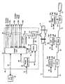
- FIG. 1illustrates an electro-mechanical actuator 10 according to the present invention controlling a fluid control valve 12 within a process fluid system for controlling the flow of fluid in a pipeline 14.
- the electro-mechanical actuator 10includes an electric motor 16 powered by a suitable voltage source on input line 18 and coupled by a drive coupler 20 to a drive gear unit 22.
- the drive unit 22may be a harmonic drive gear unit or other suitable drive gear.
- the output of the drive gear unit 22is coupled to the rotary shaft 23 of fluid control valve 12 for opening and closing the valve and thereby controlling the fluid flow in the pipeline 14.
- a control unit 24contains a microprocessor.
- a power converter 26supplies electrical power to the actuator 10 on input line 28.
- the control unit 24receives control signals from a computer 30 such as the illustrated personal computer or host computer on interconnecting line 32. In response to suitable control signals from the computer 30, the control unit 24 supplies the appropriate drive power on line 33 to the electric motor 16 to drive the drive gear 22 and thereby open and close the fluid control valve 12. Travel position data relating to the motor 16 is coupled on line 35 back to the control unit 24.
- the electro-mechanical actuator 10includes within the control unit 24 well known circuits and suitable software for providing an electronic soft start so as to avoid high start currents in the motor 16, as well as well known circuits and suitable software for controlling the maximum torque to be applied through the drive gear unit 26 to the rotary shaft 23 of the fluid control valve 12.
- an initiation signal on input line 32commands the control unit 24 to provide a power level on line 33 coupled to the electric motor 16 to begin moving the valve 12, for instance, to the fully open position.
- Limit open sensorsmonitor the valve opening and provide a limit open signal on line 34 to the control unit 24 when the open limit valve position is reached.
- limit close sensorsmonitor the valve closing and provide a limit close signal on line 36 to the control unit 24 when the close limit valve position is reached.
- the process fluid systemalso includes a second electro-mechanical actuator 40 and coupled fluid control valve 42, as well as an electro-pneumatic actuator 44 and coupled fluid control valve 46, and other field instruments 48, such as electro-pneumatic positioners, valve controllers, etc. While the aforementioned system components are shown on the same pipeline, it is to be understood that they can be on different pipelines or branch lines, etc.
- a significant advantage of the electro-mechanical actuator 10 of the present inventionis the capability to control other instruments and actuators on auxiliary control lines 50 and to monitor such control actions on auxiliary travel input lines 52.
- Each of the pair of auxiliary travel input lines 52includes a limit open line 52a and a limit closed line 52b, similar to the lines 34, 36.
- an auxiliary control output on a respective line 50activates for instance the electro-mechanical actuator 40.
- the electro-mechanical actuator 10can be utilized to activate another electro-mechanical actuator in the system such as actuator 40, or other types of instruments such as the electro-pneumatic actuator 44 and field instrument 48 as well as to monitor on respective auxiliary lines 52 when these devices have reached the desired control state in response to the control signal, such as valve fully opened or valve fully closed.
- Fig. 2wherein there is illustrated the computer 30 providing a control signal to a communications interface 60 such as a communication bus within the control unit 24.
- An input/output controller 62couples the control signal from the communications interface 60 to a suitable filter 64 or other type of signal processor, for actuating a relay or other suitable switch 66.
- the resulting control signal on a respective auxiliary control line 50 of the electro-mechanical actuator 10is coupled to one of the other field instruments, i.e., electro-mechanical actuator 40, or electro-pneumatic actuator 44 or other actuators 48 to open or close the associated valves 42, 46, 54.
- a respective auxiliary control line 50is coupled to a respective field instrument.
- the valve fully opened or valve fully closed state of the valveis monitored by a respective pair of auxiliary travel input lines 52 for coupling this information back to the control unit 24 of the electro-mechanical actuator 10.
- the limit open state of the valve 46is coupled on auxiliary travel input line 52a to a comparator 68 detecting the condition or state of the limit open sensor and, if desired, through a signal processor 70 to the input/output controller 62. If the limit open state of valve 46 has been reached, conventional limit sensors in the valve provide the limit open signal on line 52a to signal the input/output controller 62 to discontinue the valve opening control signal on the auxiliary control line 50 to the electro-pneumatic actuator 44.
- a pair of auxiliary travel input lines 52a, 52bis coupled to a respective filed instrument.
- a similar monitoring of the limit closed state of valve 46for instance, through conventional limit sensors in the valve provides a closed limit signal on the respective auxiliary travel input line 52b for coupling to the input/output controller 62 so that when the closed limit of valve 46 is reached the valve closing control signal on the respective auxiliary control line 50 to the electro-pneumatic actuator 44 is discontinued.
- a significant advantage of the unique electro-mechanical actuator 10 of the present inventionis the capability to control and monitor a plurality of other field instruments and actuators through this unique electro-mechanical actuator.
Landscapes
- Engineering & Computer Science (AREA)
- General Engineering & Computer Science (AREA)
- Mechanical Engineering (AREA)
- Electrically Driven Valve-Operating Means (AREA)
- Fluid-Pressure Circuits (AREA)
- Servomotors (AREA)
Description
- This invention relates generally to actuators for fluid flow control valves and in particular to electro-mechanical actuators.
- A variety of fluid flow control valves and corresponding valve actuators are utilized for on/off control or throttling the flow of fluid, such as in a gas or oil pipeline system, or in other process fluid systems. The fluid flow control valves are typically sliding stem control valves or rotary action control valves and are operated by a valve actuator such as an electro-pneumatic actuator piston or diaphragm unit. In a fluid flow control situation the actuator is responding to the output of a valve positioner or valve controller instrument for accurate throttling control of the valve. Another type of actuator is an electro-mechanical valve actuator containing an electric motor, a motor control unit, and a driving gear configuration with torque limiting devices for controlling the torque applied to the valve shaft. Such an actuator can contain several options, such as speed control, a modulating unit, a position transmitter, etc.
- In such process fluid systems, a variety of valve actuators, positioners, or controller instruments, etc., (hereinafter termed "field instruments") are connected to the pipeline system for controlling and/or responding to the fluid flow. Some of the present field instruments are so-called "smart" instruments containing a microprocessor so that such field instruments can be controlled from a remote location for suitably controlling the fluid flow rate, and can also provide a variety of flow characteristics as well as diagnostic information. However, the standard field instruments without microprocessors are still in substantial use and demand due to their low cost compared to a "smart" field instrument. Therefore, in many instances the process fluid system includes a mixture of "smart" field instruments as well as standard field instruments. Typically, such field instruments are connected to a bus from a controller to receive power drawn from the bus in the form of standard 4-20ma or voltage control signals.
- It is desired at times to reduce the need for large numbers of expensive, "smart" field instruments in such process fluid systems and instead to utilize larger numbers of standard field instruments where feasible. As an example, it would be desirable to utilize one expensive "smart" field instrument to control other standard field instruments, and it would be especially desirable to control other standard field instruments of different types, i.e., electro-mechanical actuators, electro-pneumatic actuators, valve controller instruments, etc., via the "smart" instrument. Secondly it is desired to control a variety of such field instruments without requiring the bus be connected to conventional control signals which otherwise draw a substantial amount of power from the bus which has somewhat limited power carrying capacity.
- US 5 428 470, relates to an automated system which comprises a modular design, wherein the modules are electrically separated from each other, and are in contact via interconnections. Such control is based upon packet based communications and the controller can be adapted to estimate the temperature of a motor for failure analysis. As such, there is no disclosure within the document to suggest that the modules are connected via a pair of travel input lines, which are designed to monitor the module.
- WO 87/04275, is directed toward a remote process control system which incorporates a plurality of controller units or slaves. The discussion is particularly directed toward an irrigation system, with each of the units or slaves being such items as a sprinkler system or sensor. No discussion, however, is presented that these could be an electric actuator or that this is electrically controlled.
- In accordance with the principles of the present invention, there is provided an electro-mechanical actuator for operating a fluid control valve and controlling the operation of a plurality field instruments. In particular there is provided an electro-mechanical actuator including a drive gear having an output coupled to another electro-pneumatic or electro-mechanical actuator. A control unit is .coupled to a power source and supplies the open and close power levels in the form of control signals to the electric motor for opening and closing the valve. The control unit includes auxiliary control means for responding to an initiation signal and providing auxiliary control power levels to the plurality of field instruments, to control the operation of the field instruments in the opening and closing of said associated fluid control valve.
- The auxiliary control means include auxiliary control output lines for connection to the plurality of field instruments, to provide auxiliary control open and close power levels to a selected field instrument, to control the opening and closing travel of a fluid control valve associated with the selected field instrument.
- The auxiliary control means, further include auxiliary monitoring means for monitoring the fully closed and fully open state of each of the valves associated with each of the field instruments, to provide a respective signal indication thereof to the auxiliary control means. A respective pair of auxiliary travel input lines, for connection to the plurality of field instruments for respectively monitoring and coupling the fully closed and fully open state of each of the associated valves to the auxiliary monitoring means. Also, to discontinue the auxiliary control open and close power levels to respective ones of the field instruments upon sensing the fully closed or fully open state of the associated valve has been reached.
- The present invention thereby provides a significant advantage in enabling a first electro-mechanical actuator having the ability to provide auxiliary control signals for actuating other field instruments.
- The features of this invention which are believed to be novel are set forth with particularity in the appended claims. The invention may be best understood by reference to the following description taken in conjunction with the accompanying drawings, in which like reference numerals identify like elements in the several figures and in which:
- Figure 1 is a schematic block diagram illustrating an electro-mechanical actuator according to the present invention utilized in a process fluid system having a variety of field instruments; and
- Figure 2 is a schematic block diagram illustrating the auxiliary control signal lines provided by the electro-mechanical actuator of Figure 1 in response to a personal computer or host computer for controlling at least two other field instruments and auxiliary travel input lines for monitoring the limit open and limit closed travel positions of the other field instruments.
- Reference may be made to the drawings which illustrate the electro-mechanical actuator of the present invention as utilized in a process control system for controlling the actuation of other field instruments.
- Figure 1 illustrates an electro-
mechanical actuator 10 according to the present invention controlling afluid control valve 12 within a process fluid system for controlling the flow of fluid in apipeline 14. The electro-mechanical actuator 10 includes anelectric motor 16 powered by a suitable voltage source oninput line 18 and coupled by adrive coupler 20 to adrive gear unit 22. Thedrive unit 22 may be a harmonic drive gear unit or other suitable drive gear. The output of thedrive gear unit 22 is coupled to therotary shaft 23 offluid control valve 12 for opening and closing the valve and thereby controlling the fluid flow in thepipeline 14. - A
control unit 24 contains a microprocessor. Apower converter 26 supplies electrical power to theactuator 10 oninput line 28. Thecontrol unit 24 receives control signals from acomputer 30 such as the illustrated personal computer or host computer on interconnectingline 32. In response to suitable control signals from thecomputer 30, thecontrol unit 24 supplies the appropriate drive power online 33 to theelectric motor 16 to drive thedrive gear 22 and thereby open and close thefluid control valve 12. Travel position data relating to themotor 16 is coupled online 35 back to thecontrol unit 24. It is understood that the electro-mechanical actuator 10 includes within thecontrol unit 24 well known circuits and suitable software for providing an electronic soft start so as to avoid high start currents in themotor 16, as well as well known circuits and suitable software for controlling the maximum torque to be applied through thedrive gear unit 26 to therotary shaft 23 of thefluid control valve 12. - In operation of the electro-
mechanical actuator 10, an initiation signal oninput line 32 commands thecontrol unit 24 to provide a power level online 33 coupled to theelectric motor 16 to begin moving thevalve 12, for instance, to the fully open position. Limit open sensors monitor the valve opening and provide a limit open signal online 34 to thecontrol unit 24 when the open limit valve position is reached. Similarly, limit close sensors monitor the valve closing and provide a limit close signal online 36 to thecontrol unit 24 when the close limit valve position is reached. - As can be seen in Figure 1, the process fluid system also includes a second electro-
mechanical actuator 40 and coupledfluid control valve 42, as well as an electro-pneumatic actuator 44 and coupled fluid control valve 46, andother field instruments 48, such as electro-pneumatic positioners, valve controllers, etc. While the aforementioned system components are shown on the same pipeline, it is to be understood that they can be on different pipelines or branch lines, etc. A significant advantage of the electro-mechanical actuator 10 of the present invention is the capability to control other instruments and actuators onauxiliary control lines 50 and to monitor such control actions on auxiliarytravel input lines 52. Each of the pair of auxiliarytravel input lines 52 includes a limitopen line 52a and a limit closedline 52b, similar to thelines - Accordingly, in response to a control signal from
computer 30 to thecontrol unit 24, an auxiliary control output on arespective line 50 activates for instance the electro-mechanical actuator 40. Thus, the electro-mechanical actuator 10 can be utilized to activate another electro-mechanical actuator in the system such asactuator 40, or other types of instruments such as the electro-pneumatic actuator 44 andfield instrument 48 as well as to monitor on respectiveauxiliary lines 52 when these devices have reached the desired control state in response to the control signal, such as valve fully opened or valve fully closed. - Reference may be made to Fig. 2 wherein there is illustrated the
computer 30 providing a control signal to acommunications interface 60 such as a communication bus within thecontrol unit 24. An input/output controller 62 couples the control signal from thecommunications interface 60 to asuitable filter 64 or other type of signal processor, for actuating a relay or othersuitable switch 66. The resulting control signal on a respectiveauxiliary control line 50 of the electro-mechanical actuator 10 is coupled to one of the other field instruments, i.e., electro-mechanical actuator 40, or electro-pneumatic actuator 44 orother actuators 48 to open or close the associatedvalves auxiliary control line 50 is coupled to a respective field instrument. - The valve fully opened or valve fully closed state of the valve, for example, of valve 46, is monitored by a respective pair of auxiliary
travel input lines 52 for coupling this information back to thecontrol unit 24 of the electro-mechanical actuator 10. For example, the limit open state of the valve 46 is coupled on auxiliarytravel input line 52a to acomparator 68 detecting the condition or state of the limit open sensor and, if desired, through asignal processor 70 to the input/output controller 62. If the limit open state of valve 46 has been reached, conventional limit sensors in the valve provide the limit open signal online 52a to signal the input/output controller 62 to discontinue the valve opening control signal on theauxiliary control line 50 to the electro-pneumatic actuator 44. A pair of auxiliarytravel input lines - A similar monitoring of the limit closed state of valve 46, for instance, through conventional limit sensors in the valve provides a closed limit signal on the respective auxiliary
travel input line 52b for coupling to the input/output controller 62 so that when the closed limit of valve 46 is reached the valve closing control signal on the respectiveauxiliary control line 50 to the electro-pneumatic actuator 44 is discontinued. - Accordingly, a significant advantage of the unique electro-
mechanical actuator 10 of the present invention is the capability to control and monitor a plurality of other field instruments and actuators through this unique electro-mechanical actuator.
Claims (3)
- An electric actuator (10) for operating a fluid control valve (14) and controlling the operation of a plurality of field instruments (40, 44, 48) having an associated fluid control valve (42, 46, 54), said electric actuator (10) comprising:a drive unit (22) having an output for coupling to said fluid control valve (14) for opening and closing the valve (14);an electric motor (16) coupled to the drive unit (22) for driving the drive unit (22) in response to open and close power levels;a control unit (24) coupled to a power source and supplying said open and close power levels to the electric motor (16) for opening and closing the valve (14);said control unit (24) including auxiliary control means (24, 32, 50) for responding to an initiation signal and providing auxiliary control power levels to said plurality of field instruments (40, 44, 48) to control the operation of said field instruments (40, 44, 48) in the opening and closing of said associated fluid control valve (42, 46, 54);said auxiliary control means (24, 32, 50) including auxiliary control output lines (50) for connection to said plurality of field instruments (40, 44, 48) to provide auxiliary control open and close power levels to a selected field instrument (40, 44, 48) to control the opening and closing travel of a fluid control valve (42, 46, 54) associated with said selected field instrument (40, 44, 48); andsaid auxiliary control means (24, 32, 50) further including auxiliary monitoring means (24, 52) for monitoring the fully closed and fully open state of each of the valves (42, 46, 54) associated with each of said field instruments (40, 44, 48) and providing a respective signal indication thereof to said auxiliary control means (24, 32, 50),characterized in thata respective pair of auxiliary travel input lines (52a, 52b) are provided for connection to said plurality of field instruments (40, 44, 48) for respectively monitoring and coupling said fully closed and fully open state of each of said associated valves (42, 46, 54) to said auxiliary monitoring means (24, 52) and to discontinue said auxiliary control open and close power levels to respective ones of said field instruments (40, 44, 48) upon sensing the fully closed or fully open state of said associated valve (42, 46, 52) has been reached.
- An electric actuator (10) according to claim 1, wherein said field instruments (40, 44, 48) include a plurality of electro-mechanical actuators (40) and electro-pneumatic actuators (44) each with an associated fluid control valve (42, 46).
- An electric actuator according to claim 2, wherein each of said field instruments (40, 44, 48) is coupled to a respective auxiliary control output line (50) and to a respective pair of auxiliary input lines (52a, 52b).
Applications Claiming Priority (3)
| Application Number | Priority Date | Filing Date | Title |
|---|---|---|---|
| US09/553,579US6371162B1 (en) | 2000-04-20 | 2000-04-20 | Electric actuator for fluid control valves |
| US553579 | 2000-04-20 | ||
| PCT/US2001/040530WO2001081802A2 (en) | 2000-04-20 | 2001-04-13 | Electric actuator for fluid control valves |
Publications (2)
| Publication Number | Publication Date |
|---|---|
| EP1278977A2 EP1278977A2 (en) | 2003-01-29 |
| EP1278977B1true EP1278977B1 (en) | 2006-02-08 |
Family
ID=24209958
Family Applications (1)
| Application Number | Title | Priority Date | Filing Date |
|---|---|---|---|
| EP01929056AExpired - LifetimeEP1278977B1 (en) | 2000-04-20 | 2001-04-13 | Electric actuator for fluid control valves |
Country Status (10)
| Country | Link |
|---|---|
| US (1) | US6371162B1 (en) |
| EP (1) | EP1278977B1 (en) |
| JP (1) | JP4805519B2 (en) |
| CN (1) | CN1182448C (en) |
| AU (1) | AU2001255842A1 (en) |
| BR (1) | BR0110203B1 (en) |
| CA (1) | CA2406844C (en) |
| DE (1) | DE60117137T2 (en) |
| TW (1) | TW593914B (en) |
| WO (1) | WO2001081802A2 (en) |
Families Citing this family (23)
| Publication number | Priority date | Publication date | Assignee | Title |
|---|---|---|---|---|
| US20050205824A1 (en)* | 2004-03-18 | 2005-09-22 | Osborne Charles A | Segmented ball control valve with universal end connections |
| JP4573197B2 (en)* | 2005-07-21 | 2010-11-04 | Smc株式会社 | Solenoid valve drive control device |
| JP4680782B2 (en)* | 2006-01-16 | 2011-05-11 | 株式会社山武 | Electric actuator and operation confirmation system for electric actuator |
| US7735805B2 (en)* | 2006-03-03 | 2010-06-15 | Boyd Cornell | Water control valve |
| MX359908B (en)* | 2008-07-18 | 2018-10-16 | Flowserve Man Co | Variable speed actuator. |
| US10094485B2 (en) | 2008-07-18 | 2018-10-09 | Flowserve Management Company | Variable-speed actuator |
| JP5150408B2 (en)* | 2008-08-19 | 2013-02-20 | 矢崎エナジーシステム株式会社 | Shut-off system |
| DE102009006533B4 (en)* | 2009-01-28 | 2011-06-30 | Siemens Aktiengesellschaft, 80333 | Actuator with an open / close valve |
| DE102009034193A1 (en)* | 2009-07-22 | 2011-02-03 | Voith Patent Gmbh | Turbo compound system for a drive device |
| US8636262B2 (en)* | 2009-11-13 | 2014-01-28 | Fisher Controls International, Llc | Coupling apparatus for use with electric actuators |
| US8408518B2 (en)* | 2009-11-13 | 2013-04-02 | Fisher Controls International, Llc | Electric actuators having internal load apparatus |
| US8727284B2 (en)* | 2010-01-22 | 2014-05-20 | Hamilton Sundstrand Corporation | Turbine powered electromechanical actuation system |
| CN102822577B (en)* | 2010-04-14 | 2014-11-19 | 博格华纳公司 | multi-function valve |
| CN102072353A (en)* | 2010-12-31 | 2011-05-25 | 上海新拓电力设备有限公司 | Intelligent reciprocating type driving and controlling system of coal valve |
| US8979063B2 (en) | 2011-11-28 | 2015-03-17 | Fisher Controls International Llc | Failsafe apparatus for use with linear actuators |
| CN103470955B (en)* | 2013-09-11 | 2016-01-27 | 湖北汽车工业学院 | Flux locking closure is determined in a kind of logical fluid circuit |
| CN105934619B (en)* | 2014-01-29 | 2018-09-14 | 丹佛斯有限公司 | It is connected to the motor-driven actuator of one or more other components |
| CN109416136B (en) | 2016-03-03 | 2020-10-16 | 爱默生过程管理阀门自动化公司 | Method and device for automatically detecting a faulty configuration of a pneumatic actuator |
| WO2018079586A1 (en)* | 2016-10-26 | 2018-05-03 | 株式会社フジキン | Flow restrictor and flow control device in which same is used |
| US11408451B2 (en) | 2018-10-12 | 2022-08-09 | Bray International, Inc. | Smart valve with integrated electronics |
| EP3891422A1 (en) | 2018-12-06 | 2021-10-13 | Bray International, Inc. | Smart valve adaptor with integrated electronics |
| CA3163447A1 (en) | 2020-01-03 | 2021-07-08 | Bray International, Inc. | Valve with load cell |
| JP2021144376A (en)* | 2020-03-11 | 2021-09-24 | 日本ギア工業株式会社 | Electric valve actuator and system using the electric valve actuator |
Family Cites Families (31)
| Publication number | Priority date | Publication date | Assignee | Title |
|---|---|---|---|---|
| US4034774A (en)* | 1975-07-07 | 1977-07-12 | Lone Star Gas Company | Low point control system |
| US4142860A (en)* | 1976-06-23 | 1979-03-06 | Mayeaux Donald P | Apparatus for producing a calibration sample for analytical instrumentation |
| US4185650A (en)* | 1977-06-20 | 1980-01-29 | Neves William T | Method and apparatus for trouble-shooting and irrigation system |
| IL55401A (en)* | 1977-08-31 | 1980-10-26 | Anarec Sa | Apparatus for the treatment of fluids |
| US4177395A (en) | 1977-12-19 | 1979-12-04 | Rotork Limited | Actuators |
| US4165532A (en)* | 1977-12-30 | 1979-08-21 | The Toro Company | Automatic irrigation sprinkler system controller |
| US4209131A (en)* | 1978-05-12 | 1980-06-24 | Motorola, Inc. | Computer-controlled irrigation system |
| US4270573A (en)* | 1978-07-25 | 1981-06-02 | Hydronic Systems, Inc. | Controller for fluid flow systems |
| GB2101355B (en) | 1981-04-30 | 1985-01-16 | Rotork Controls | Control of valve actuator |
| US4372334A (en)* | 1981-05-18 | 1983-02-08 | Continental Disc Corporation | Overpressure relief control system |
| GB2120349B (en) | 1982-05-12 | 1985-08-29 | Rotork Controls | Valve actuators having alternative manual and power inputs |
| US4584902A (en) | 1982-06-12 | 1986-04-29 | Rotork Controls Limited | Valve actuators |
| US4495968A (en)* | 1982-07-16 | 1985-01-29 | Combined Fluid Products Company | Pneumatic control system |
| EP0252131A1 (en) | 1986-01-14 | 1988-01-13 | Auditel Systems Pty. Ltd. | Remote process control apparatus |
| US4819149A (en) | 1986-05-02 | 1989-04-04 | Owens-Corning Fiberglas Corporation | Distributed control system |
| US4994001A (en) | 1988-03-24 | 1991-02-19 | Limitorque Corporation | Valve actuator differential worm planetary gear drive |
| US4940011A (en) | 1989-05-19 | 1990-07-10 | Limitorque Corporation | Valve actuator two rotor three position indicator |
| US5154349A (en)* | 1991-09-23 | 1992-10-13 | Vaughn David H | Maintenance control apparatus for lawn watering system |
| US5428470A (en) | 1992-07-17 | 1995-06-27 | Beckman Instruments, Inc. | Modular system and method for an automatic analyzer |
| EP0608245B1 (en)* | 1992-08-19 | 1996-10-09 | Festo KG | Electro-pneumatic control device |
| DE4234421A1 (en)* | 1992-10-13 | 1994-04-14 | Bosch Gmbh Robert | Device for the current-controlled control of several actuators by means of a control computer |
| US5287888A (en)* | 1993-01-15 | 1994-02-22 | Geiger James E | Irrigation controller |
| JPH07199801A (en)* | 1993-12-27 | 1995-08-04 | Canon Inc | Programmable controller system |
| US5934302A (en)* | 1996-05-01 | 1999-08-10 | Nemelka; Mark S. | Control valve apparatus and method for regulating fluid flow in fluid-intake machines |
| US5873388A (en)* | 1996-06-07 | 1999-02-23 | Atmi Ecosys Corporation | System for stabilization of pressure perturbations from oxidation systems for treatment of process gases from semiconductor manufacturing operations |
| JPH10177401A (en)* | 1996-12-16 | 1998-06-30 | Yokogawa Electric Corp | Fieldbus system |
| US5944052A (en)* | 1997-05-05 | 1999-08-31 | Rashidi; Ardishir | Multiple outlets self-actuated irrigation valve |
| FR2769385B1 (en) | 1997-10-07 | 2000-01-28 | Crouzet Automatismes | PROGRAMMABLE CONTROLLER CAPABLE OF DETECTING AN INSULATION FAULT ON A NETWORK TO WHICH IT IS CONNECTED |
| JPH11119808A (en)* | 1997-10-17 | 1999-04-30 | Yokogawa Electric Corp | Plant control system using fieldbus |
| US6173727B1 (en)* | 1998-05-06 | 2001-01-16 | Donald Davey | Remote control sprinkler control system |
| US6129103A (en)* | 1999-09-15 | 2000-10-10 | Fields; Acie R. | Timed control valve and method of using the same |
- 2000
- 2000-04-20USUS09/553,579patent/US6371162B1/ennot_activeExpired - Lifetime
- 2001
- 2001-04-13DEDE60117137Tpatent/DE60117137T2/ennot_activeExpired - Lifetime
- 2001-04-13CACA002406844Apatent/CA2406844C/ennot_activeExpired - Lifetime
- 2001-04-13AUAU2001255842Apatent/AU2001255842A1/ennot_activeAbandoned
- 2001-04-13CNCNB018101445Apatent/CN1182448C/ennot_activeExpired - Fee Related
- 2001-04-13WOPCT/US2001/040530patent/WO2001081802A2/enactiveIP Right Grant
- 2001-04-13EPEP01929056Apatent/EP1278977B1/ennot_activeExpired - Lifetime
- 2001-04-13JPJP2001578854Apatent/JP4805519B2/ennot_activeExpired - Lifetime
- 2001-04-13BRBRPI0110203-6Apatent/BR0110203B1/enactiveIP Right Grant
- 2001-04-20TWTW090109522Apatent/TW593914B/ennot_activeIP Right Cessation
Also Published As
| Publication number | Publication date |
|---|---|
| WO2001081802A3 (en) | 2002-04-04 |
| EP1278977A2 (en) | 2003-01-29 |
| CA2406844A1 (en) | 2001-11-01 |
| TW593914B (en) | 2004-06-21 |
| CN1430740A (en) | 2003-07-16 |
| CN1182448C (en) | 2004-12-29 |
| US6371162B1 (en) | 2002-04-16 |
| DE60117137D1 (en) | 2006-04-20 |
| DE60117137T2 (en) | 2006-10-26 |
| AU2001255842A1 (en) | 2001-11-07 |
| JP2003532180A (en) | 2003-10-28 |
| JP4805519B2 (en) | 2011-11-02 |
| CA2406844C (en) | 2006-12-05 |
| WO2001081802A2 (en) | 2001-11-01 |
| BR0110203A (en) | 2003-07-15 |
| BR0110203B1 (en) | 2014-11-04 |
| HK1057403A1 (en) | 2004-04-02 |
Similar Documents
| Publication | Publication Date | Title |
|---|---|---|
| EP1278977B1 (en) | Electric actuator for fluid control valves | |
| EP1161636B1 (en) | Emergency shutdown test system | |
| CN101228485B (en) | Emergency shutdown system | |
| EP2241415B1 (en) | Robot system | |
| WO2004011812A2 (en) | Actuator control system for hydraulic devices | |
| US20150378370A1 (en) | Valve Assembly and Fluidic System | |
| CN101368582A (en) | Valve module | |
| JP2021518613A (en) | Field device latch relay reset | |
| US20080154436A1 (en) | Control device for a pneumatically operated actuator | |
| US7466099B2 (en) | Multi-mode manipulator arm and drive system | |
| CN102854869A (en) | Monitoring system and plate scrapping device | |
| US20080288129A1 (en) | Vehicle Control System | |
| US20100219961A1 (en) | Limit signal indicator and method for operating a limit signal indicator | |
| HK1057403B (en) | Electric actuator for fluid control valves | |
| EP1837131A1 (en) | Manipulator, for example an industrial robot, and drive device for a manipulator | |
| JP3735051B2 (en) | Valve positioner | |
| JP5064326B2 (en) | Valve controller for petrochemical plant | |
| CN223105414U (en) | Intelligent variable frequency regulation electro-hydraulic actuator control system | |
| JP2572967B2 (en) | Electric actuator for driving valves with built-in electronic control unit | |
| JPH01141202A (en) | Positioner having communication function | |
| JPH07123032A (en) | Fieldbus compatible actuator | |
| SU1149044A1 (en) | Power plant automatic control system | |
| JPH08270830A (en) | Valve control method | |
| WO1990015278A1 (en) | Apparatus comprising a valve | |
| MXPA97002915A (en) | Apparatus for providing access to field devices in a distribution control system |
Legal Events
| Date | Code | Title | Description |
|---|---|---|---|
| PUAI | Public reference made under article 153(3) epc to a published international application that has entered the european phase | Free format text:ORIGINAL CODE: 0009012 | |
| 17P | Request for examination filed | Effective date:20021115 | |
| AK | Designated contracting states | Designated state(s):AT BE CH CY DE DK ES FI FR GB GR IE IT LI LU MC NL PT SE TR | |
| AX | Request for extension of the european patent | Extension state:AL LT LV MK RO SI | |
| RBV | Designated contracting states (corrected) | Designated state(s):AT BE CH CY DE FI FR GB LI SE | |
| RAP1 | Party data changed (applicant data changed or rights of an application transferred) | Owner name:FISHER CONTROLS INTERNATIONAL LLC | |
| 17Q | First examination report despatched | Effective date:20041111 | |
| GRAP | Despatch of communication of intention to grant a patent | Free format text:ORIGINAL CODE: EPIDOSNIGR1 | |
| RBV | Designated contracting states (corrected) | Designated state(s):DE FI FR GB SE | |
| GRAS | Grant fee paid | Free format text:ORIGINAL CODE: EPIDOSNIGR3 | |
| GRAA | (expected) grant | Free format text:ORIGINAL CODE: 0009210 | |
| AK | Designated contracting states | Kind code of ref document:B1 Designated state(s):DE FI FR GB SE | |
| REG | Reference to a national code | Ref country code:GB Ref legal event code:FG4D | |
| REG | Reference to a national code | Ref country code:SE Ref legal event code:TRGR | |
| REF | Corresponds to: | Ref document number:60117137 Country of ref document:DE Date of ref document:20060420 Kind code of ref document:P | |
| ET | Fr: translation filed | ||
| PLBE | No opposition filed within time limit | Free format text:ORIGINAL CODE: 0009261 | |
| STAA | Information on the status of an ep patent application or granted ep patent | Free format text:STATUS: NO OPPOSITION FILED WITHIN TIME LIMIT | |
| 26N | No opposition filed | Effective date:20061109 | |
| REG | Reference to a national code | Ref country code:GB Ref legal event code:732E Free format text:REGISTERED BETWEEN 20090521 AND 20090527 | |
| REG | Reference to a national code | Ref country code:FR Ref legal event code:TP | |
| REG | Reference to a national code | Ref country code:FR Ref legal event code:PLFP Year of fee payment:16 | |
| REG | Reference to a national code | Ref country code:FR Ref legal event code:PLFP Year of fee payment:17 | |
| REG | Reference to a national code | Ref country code:FR Ref legal event code:PLFP Year of fee payment:18 | |
| PGFP | Annual fee paid to national office [announced via postgrant information from national office to epo] | Ref country code:DE Payment date:20190429 Year of fee payment:19 Ref country code:FI Payment date:20190429 Year of fee payment:19 | |
| PGFP | Annual fee paid to national office [announced via postgrant information from national office to epo] | Ref country code:SE Payment date:20190429 Year of fee payment:19 Ref country code:FR Payment date:20190425 Year of fee payment:19 | |
| PGFP | Annual fee paid to national office [announced via postgrant information from national office to epo] | Ref country code:GB Payment date:20190429 Year of fee payment:19 | |
| REG | Reference to a national code | Ref country code:DE Ref legal event code:R119 Ref document number:60117137 Country of ref document:DE | |
| REG | Reference to a national code | Ref country code:FI Ref legal event code:MAE | |
| PG25 | Lapsed in a contracting state [announced via postgrant information from national office to epo] | Ref country code:DE Free format text:LAPSE BECAUSE OF NON-PAYMENT OF DUE FEES Effective date:20201103 Ref country code:FI Free format text:LAPSE BECAUSE OF NON-PAYMENT OF DUE FEES Effective date:20200413 Ref country code:FR Free format text:LAPSE BECAUSE OF NON-PAYMENT OF DUE FEES Effective date:20200430 Ref country code:SE Free format text:LAPSE BECAUSE OF NON-PAYMENT OF DUE FEES Effective date:20200414 | |
| GBPC | Gb: european patent ceased through non-payment of renewal fee | Effective date:20200413 | |
| PG25 | Lapsed in a contracting state [announced via postgrant information from national office to epo] | Ref country code:GB Free format text:LAPSE BECAUSE OF NON-PAYMENT OF DUE FEES Effective date:20200413 |