EP1273120B1 - Frame-based communication with variable rate payload - Google Patents
Frame-based communication with variable rate payloadDownload PDFInfo
- Publication number
- EP1273120B1 EP1273120B1EP01923096AEP01923096AEP1273120B1EP 1273120 B1EP1273120 B1EP 1273120B1EP 01923096 AEP01923096 AEP 01923096AEP 01923096 AEP01923096 AEP 01923096AEP 1273120 B1EP1273120 B1EP 1273120B1
- Authority
- EP
- European Patent Office
- Prior art keywords
- frame
- node
- network
- clock
- master
- Prior art date
- Legal status (The legal status is an assumption and is not a legal conclusion. Google has not performed a legal analysis and makes no representation as to the accuracy of the status listed.)
- Expired - Lifetime
Links
Images


Classifications
- H—ELECTRICITY
- H04—ELECTRIC COMMUNICATION TECHNIQUE
- H04L—TRANSMISSION OF DIGITAL INFORMATION, e.g. TELEGRAPHIC COMMUNICATION
- H04L1/00—Arrangements for detecting or preventing errors in the information received
- H04L1/0001—Systems modifying transmission characteristics according to link quality, e.g. power backoff
- H04L1/0002—Systems modifying transmission characteristics according to link quality, e.g. power backoff by adapting the transmission rate
- H04L1/0003—Systems modifying transmission characteristics according to link quality, e.g. power backoff by adapting the transmission rate by switching between different modulation schemes
- H04L1/0005—Systems modifying transmission characteristics according to link quality, e.g. power backoff by adapting the transmission rate by switching between different modulation schemes applied to payload information
- H—ELECTRICITY
- H04—ELECTRIC COMMUNICATION TECHNIQUE
- H04L—TRANSMISSION OF DIGITAL INFORMATION, e.g. TELEGRAPHIC COMMUNICATION
- H04L1/00—Arrangements for detecting or preventing errors in the information received
- H04L1/0001—Systems modifying transmission characteristics according to link quality, e.g. power backoff
- H04L1/0002—Systems modifying transmission characteristics according to link quality, e.g. power backoff by adapting the transmission rate
- H04L1/0003—Systems modifying transmission characteristics according to link quality, e.g. power backoff by adapting the transmission rate by switching between different modulation schemes
- H—ELECTRICITY
- H04—ELECTRIC COMMUNICATION TECHNIQUE
- H04L—TRANSMISSION OF DIGITAL INFORMATION, e.g. TELEGRAPHIC COMMUNICATION
- H04L1/00—Arrangements for detecting or preventing errors in the information received
- H04L1/0001—Systems modifying transmission characteristics according to link quality, e.g. power backoff
- H04L1/0006—Systems modifying transmission characteristics according to link quality, e.g. power backoff by adapting the transmission format
- H—ELECTRICITY
- H04—ELECTRIC COMMUNICATION TECHNIQUE
- H04L—TRANSMISSION OF DIGITAL INFORMATION, e.g. TELEGRAPHIC COMMUNICATION
- H04L1/00—Arrangements for detecting or preventing errors in the information received
- H04L1/0001—Systems modifying transmission characteristics according to link quality, e.g. power backoff
- H04L1/0009—Systems modifying transmission characteristics according to link quality, e.g. power backoff by adapting the channel coding
- H—ELECTRICITY
- H04—ELECTRIC COMMUNICATION TECHNIQUE
- H04L—TRANSMISSION OF DIGITAL INFORMATION, e.g. TELEGRAPHIC COMMUNICATION
- H04L1/00—Arrangements for detecting or preventing errors in the information received
- H04L1/0001—Systems modifying transmission characteristics according to link quality, e.g. power backoff
- H04L1/0023—Systems modifying transmission characteristics according to link quality, e.g. power backoff characterised by the signalling
- H04L1/0025—Transmission of mode-switching indication
- H—ELECTRICITY
- H04—ELECTRIC COMMUNICATION TECHNIQUE
- H04L—TRANSMISSION OF DIGITAL INFORMATION, e.g. TELEGRAPHIC COMMUNICATION
- H04L1/00—Arrangements for detecting or preventing errors in the information received
- H04L1/004—Arrangements for detecting or preventing errors in the information received by using forward error control
- H04L1/0072—Error control for data other than payload data, e.g. control data
- H—ELECTRICITY
- H04—ELECTRIC COMMUNICATION TECHNIQUE
- H04L—TRANSMISSION OF DIGITAL INFORMATION, e.g. TELEGRAPHIC COMMUNICATION
- H04L1/00—Arrangements for detecting or preventing errors in the information received
- H04L1/12—Arrangements for detecting or preventing errors in the information received by using return channel
- H04L1/16—Arrangements for detecting or preventing errors in the information received by using return channel in which the return channel carries supervisory signals, e.g. repetition request signals
- H04L1/18—Automatic repetition systems, e.g. Van Duuren systems
- H04L1/1809—Selective-repeat protocols
- H—ELECTRICITY
- H04—ELECTRIC COMMUNICATION TECHNIQUE
- H04L—TRANSMISSION OF DIGITAL INFORMATION, e.g. TELEGRAPHIC COMMUNICATION
- H04L1/00—Arrangements for detecting or preventing errors in the information received
- H04L1/12—Arrangements for detecting or preventing errors in the information received by using return channel
- H04L1/16—Arrangements for detecting or preventing errors in the information received by using return channel in which the return channel carries supervisory signals, e.g. repetition request signals
- H04L1/18—Automatic repetition systems, e.g. Van Duuren systems
- H04L1/1829—Arrangements specially adapted for the receiver end
- H04L1/1848—Time-out mechanisms
- H—ELECTRICITY
- H04—ELECTRIC COMMUNICATION TECHNIQUE
- H04L—TRANSMISSION OF DIGITAL INFORMATION, e.g. TELEGRAPHIC COMMUNICATION
- H04L1/00—Arrangements for detecting or preventing errors in the information received
- H04L1/12—Arrangements for detecting or preventing errors in the information received by using return channel
- H04L1/16—Arrangements for detecting or preventing errors in the information received by using return channel in which the return channel carries supervisory signals, e.g. repetition request signals
- H04L1/18—Automatic repetition systems, e.g. Van Duuren systems
- H04L1/1867—Arrangements specially adapted for the transmitter end
- H04L1/1874—Buffer management
- H04L1/1877—Buffer management for semi-reliable protocols, e.g. for less sensitive applications like streaming video
- H—ELECTRICITY
- H04—ELECTRIC COMMUNICATION TECHNIQUE
- H04L—TRANSMISSION OF DIGITAL INFORMATION, e.g. TELEGRAPHIC COMMUNICATION
- H04L1/00—Arrangements for detecting or preventing errors in the information received
- H04L1/12—Arrangements for detecting or preventing errors in the information received by using return channel
- H04L1/16—Arrangements for detecting or preventing errors in the information received by using return channel in which the return channel carries supervisory signals, e.g. repetition request signals
- H04L1/18—Automatic repetition systems, e.g. Van Duuren systems
- H04L1/1867—Arrangements specially adapted for the transmitter end
- H04L1/188—Time-out mechanisms
- H04L1/1883—Time-out mechanisms using multiple timers
- H—ELECTRICITY
- H04—ELECTRIC COMMUNICATION TECHNIQUE
- H04L—TRANSMISSION OF DIGITAL INFORMATION, e.g. TELEGRAPHIC COMMUNICATION
- H04L1/00—Arrangements for detecting or preventing errors in the information received
- H04L1/12—Arrangements for detecting or preventing errors in the information received by using return channel
- H04L1/16—Arrangements for detecting or preventing errors in the information received by using return channel in which the return channel carries supervisory signals, e.g. repetition request signals
- H04L1/18—Automatic repetition systems, e.g. Van Duuren systems
- H04L1/1867—Arrangements specially adapted for the transmitter end
- H04L1/1887—Scheduling and prioritising arrangements
- H—ELECTRICITY
- H04—ELECTRIC COMMUNICATION TECHNIQUE
- H04L—TRANSMISSION OF DIGITAL INFORMATION, e.g. TELEGRAPHIC COMMUNICATION
- H04L1/00—Arrangements for detecting or preventing errors in the information received
- H04L1/20—Arrangements for detecting or preventing errors in the information received using signal quality detector
- H—ELECTRICITY
- H04—ELECTRIC COMMUNICATION TECHNIQUE
- H04L—TRANSMISSION OF DIGITAL INFORMATION, e.g. TELEGRAPHIC COMMUNICATION
- H04L12/00—Data switching networks
- H04L12/28—Data switching networks characterised by path configuration, e.g. LAN [Local Area Networks] or WAN [Wide Area Networks]
- H04L12/40—Bus networks
- H04L12/40006—Architecture of a communication node
- H04L12/40032—Details regarding a bus interface enhancer
- H—ELECTRICITY
- H04—ELECTRIC COMMUNICATION TECHNIQUE
- H04L—TRANSMISSION OF DIGITAL INFORMATION, e.g. TELEGRAPHIC COMMUNICATION
- H04L12/00—Data switching networks
- H04L12/28—Data switching networks characterised by path configuration, e.g. LAN [Local Area Networks] or WAN [Wide Area Networks]
- H04L12/40—Bus networks
- H04L12/4013—Management of data rate on the bus
- H04L12/40136—Nodes adapting their rate to the physical link properties
- H—ELECTRICITY
- H04—ELECTRIC COMMUNICATION TECHNIQUE
- H04L—TRANSMISSION OF DIGITAL INFORMATION, e.g. TELEGRAPHIC COMMUNICATION
- H04L12/00—Data switching networks
- H04L12/28—Data switching networks characterised by path configuration, e.g. LAN [Local Area Networks] or WAN [Wide Area Networks]
- H04L12/40—Bus networks
- H04L12/40143—Bus networks involving priority mechanisms
- H04L12/40156—Bus networks involving priority mechanisms by using dedicated slots associated with a priority level
- H—ELECTRICITY
- H04—ELECTRIC COMMUNICATION TECHNIQUE
- H04L—TRANSMISSION OF DIGITAL INFORMATION, e.g. TELEGRAPHIC COMMUNICATION
- H04L12/00—Data switching networks
- H04L12/28—Data switching networks characterised by path configuration, e.g. LAN [Local Area Networks] or WAN [Wide Area Networks]
- H04L12/40—Bus networks
- H04L12/40143—Bus networks involving priority mechanisms
- H04L12/40163—Bus networks involving priority mechanisms by assigning priority to messages according to a message field
- H—ELECTRICITY
- H04—ELECTRIC COMMUNICATION TECHNIQUE
- H04L—TRANSMISSION OF DIGITAL INFORMATION, e.g. TELEGRAPHIC COMMUNICATION
- H04L12/00—Data switching networks
- H04L12/28—Data switching networks characterised by path configuration, e.g. LAN [Local Area Networks] or WAN [Wide Area Networks]
- H04L12/40—Bus networks
- H04L12/403—Bus networks with centralised control, e.g. polling
- H04L12/4035—Bus networks with centralised control, e.g. polling in which slots of a TDMA packet structure are assigned based on a contention resolution carried out at a master unit
- H—ELECTRICITY
- H04—ELECTRIC COMMUNICATION TECHNIQUE
- H04L—TRANSMISSION OF DIGITAL INFORMATION, e.g. TELEGRAPHIC COMMUNICATION
- H04L12/00—Data switching networks
- H04L12/28—Data switching networks characterised by path configuration, e.g. LAN [Local Area Networks] or WAN [Wide Area Networks]
- H04L12/40—Bus networks
- H04L12/407—Bus networks with decentralised control
- H04L12/413—Bus networks with decentralised control with random access, e.g. carrier-sense multiple-access with collision detection [CSMA-CD]
- H—ELECTRICITY
- H04—ELECTRIC COMMUNICATION TECHNIQUE
- H04M—TELEPHONIC COMMUNICATION
- H04M11/00—Telephonic communication systems specially adapted for combination with other electrical systems
- H—ELECTRICITY
- H04—ELECTRIC COMMUNICATION TECHNIQUE
- H04M—TELEPHONIC COMMUNICATION
- H04M11/00—Telephonic communication systems specially adapted for combination with other electrical systems
- H04M11/06—Simultaneous speech and data transmission, e.g. telegraphic transmission over the same conductors
- H—ELECTRICITY
- H04—ELECTRIC COMMUNICATION TECHNIQUE
- H04L—TRANSMISSION OF DIGITAL INFORMATION, e.g. TELEGRAPHIC COMMUNICATION
- H04L1/00—Arrangements for detecting or preventing errors in the information received
- H04L1/004—Arrangements for detecting or preventing errors in the information received by using forward error control
- H04L1/0056—Systems characterized by the type of code used
- H04L1/0061—Error detection codes
- H—ELECTRICITY
- H04—ELECTRIC COMMUNICATION TECHNIQUE
- H04L—TRANSMISSION OF DIGITAL INFORMATION, e.g. TELEGRAPHIC COMMUNICATION
- H04L1/00—Arrangements for detecting or preventing errors in the information received
- H04L1/08—Arrangements for detecting or preventing errors in the information received by repeating transmission, e.g. Verdan system
- H—ELECTRICITY
- H04—ELECTRIC COMMUNICATION TECHNIQUE
- H04L—TRANSMISSION OF DIGITAL INFORMATION, e.g. TELEGRAPHIC COMMUNICATION
- H04L12/00—Data switching networks
- H04L12/28—Data switching networks characterised by path configuration, e.g. LAN [Local Area Networks] or WAN [Wide Area Networks]
- H04L12/40—Bus networks
- H04L12/4013—Management of data rate on the bus
- H—ELECTRICITY
- H04—ELECTRIC COMMUNICATION TECHNIQUE
- H04L—TRANSMISSION OF DIGITAL INFORMATION, e.g. TELEGRAPHIC COMMUNICATION
- H04L12/00—Data switching networks
- H04L12/28—Data switching networks characterised by path configuration, e.g. LAN [Local Area Networks] or WAN [Wide Area Networks]
- H04L12/40—Bus networks
- H04L12/403—Bus networks with centralised control, e.g. polling
- H—ELECTRICITY
- H04—ELECTRIC COMMUNICATION TECHNIQUE
- H04L—TRANSMISSION OF DIGITAL INFORMATION, e.g. TELEGRAPHIC COMMUNICATION
- H04L12/00—Data switching networks
- H04L12/28—Data switching networks characterised by path configuration, e.g. LAN [Local Area Networks] or WAN [Wide Area Networks]
- H04L12/40—Bus networks
- H04L12/407—Bus networks with decentralised control
- H04L12/417—Bus networks with decentralised control with deterministic access, e.g. token passing
- H—ELECTRICITY
- H04—ELECTRIC COMMUNICATION TECHNIQUE
- H04L—TRANSMISSION OF DIGITAL INFORMATION, e.g. TELEGRAPHIC COMMUNICATION
- H04L1/00—Arrangements for detecting or preventing errors in the information received
- H04L2001/0092—Error control systems characterised by the topology of the transmission link
- H04L2001/0093—Point-to-multipoint
- H—ELECTRICITY
- H04—ELECTRIC COMMUNICATION TECHNIQUE
- H04L—TRANSMISSION OF DIGITAL INFORMATION, e.g. TELEGRAPHIC COMMUNICATION
- H04L1/00—Arrangements for detecting or preventing errors in the information received
- H04L1/12—Arrangements for detecting or preventing errors in the information received by using return channel
- H04L2001/125—Arrangements for preventing errors in the return channel
- Y—GENERAL TAGGING OF NEW TECHNOLOGICAL DEVELOPMENTS; GENERAL TAGGING OF CROSS-SECTIONAL TECHNOLOGIES SPANNING OVER SEVERAL SECTIONS OF THE IPC; TECHNICAL SUBJECTS COVERED BY FORMER USPC CROSS-REFERENCE ART COLLECTIONS [XRACs] AND DIGESTS
- Y02—TECHNOLOGIES OR APPLICATIONS FOR MITIGATION OR ADAPTATION AGAINST CLIMATE CHANGE
- Y02D—CLIMATE CHANGE MITIGATION TECHNOLOGIES IN INFORMATION AND COMMUNICATION TECHNOLOGIES [ICT], I.E. INFORMATION AND COMMUNICATION TECHNOLOGIES AIMING AT THE REDUCTION OF THEIR OWN ENERGY USE
- Y02D30/00—Reducing energy consumption in communication networks
- Y02D30/50—Reducing energy consumption in communication networks in wire-line communication networks, e.g. low power modes or reduced link rate
Definitions
- the present inventionrelates to the field of communications, and, in particular, to a frame-based communications network.
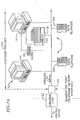
- Fig. 1ashows in block diagram form a general home networking environment within which the present invention can be implemented.
- Home network 10includes existing (installed) plain old telephone service (POTS) wiring 12, network clients 14, the computer port side of modem 16 and fax 18.
- POTS wiring 12provides wiring infrastructure used to network multiple clients at a customer premises (e.g., home) 20.
- POTS wiring 12can be conventional unshielded twisted pair (UTP) wiring that is generally routed internally in the walls of the customer premises 20 to various locations (e.g., rooms) within the customer premises.
- Subscriber loop 22(also called a "local loop") is a physical wiring link that directly connects an individual customer premises 20 to the Central Office through telephone network interface 24, a demarcation point between the inside and outside of customer premises 20.
- UTPunshielded twisted pair
- Subscriber loop 22also called a "local loop" is a physical wiring link that directly connects an individual customer premises 20 to the Central Office through telephone network interface 24, a demarcation point between the
- home phone-line network configuration 10can also utilize interface 6010 to provide signals outside customer premises 20.
- interface 6010can include a V.90 modem as described above, connected through the central office to an internet service provider.
- Interface 6010can include an ADSL modem, a VDSL modem or the like transport interface.
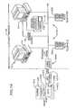
- CMTScable modem termination system
- HFChybrid fiber coaxial
- HFC networksare commonly utilized by cable providers to provide Internet access, cable television, pay-per-view and the like to subscribers.
- Approximately 500 homes 1014are in electrical communication with each node 1016,1034 of the HFC network 1010, typically via coaxial cable 1029,1030,1031.
- Amplifiers 1015facilitate the electrical connection of the more distant homes 1014 to the nodes 1016,1034 by boosting the electrical signals so as to desirably enhance the signal-to-noise ratio of such communications and by then transmitting the electrical signals over coaxial conductors 1030, 1031.
- Coaxial conductors 1029electrically interconnect the homes 1014 with the coaxial conductors 1030,1031, which extend between amplifiers 1015 and nodes 1016,1034.
- Each node 1016, 1034is electrically connected to a hub 1022, 1024, typically via an optical fiber 1028, 1032.
- the hubs 1022, 1024are in communication with the headend 1012, via optical fiber 1020, 1026.
- Each hubis typically capable of facilitating communication with approximately 20,000 homes 1014.
- the optical fiber 1020,1026 extending intermediate the headend 1012 and each hub 1022, 1024defines a fiber ring which is typically capable of facilitating communication between approximately 100,000 homes 1014 and the headend 1012.
- the headend 1012may include video servers, satellite receivers, video modulators, telephone switches and/or Internet routers 1018, as well as the CMTS.
- the headend 1012communicates via transmission line 1013, which may be a T1 or T2 line, with the Internet, other headends and/or any other desired device(s) or network.
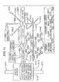
- Fig. 1ddepicts such an integrated environment.
- a connection point in the home to the telephony worlde.g., the world of video, voice, high speed data network traffic
- cable modem 1046which would include an HPNA transceiver.
- the cable modem system providermay also wish to accomodate providing telephone service along with high speed data service.
- a home computer userrather than using a traditional modem to connect to an internet service provider, would find it convenient to utilize cable modem 1046, taking advantage of the very high speed data service provided by the cable modem. Having a cable modem customer, the cable modem provider may also find it commercially beneficial to offer video feeds, and telephone service over the same cable modem network.
- a cable modem having an HPNA V2 transceiver included thereincan readily interface into the home phone line network through the telephone jack within the home.
- Computers coupled to the home networkthen communicate through the cable modem to the outside telephony world as described above.
- Telephone service coming from outside the customer premises over the cable modem systemwould be in a digitized packetized format. It would then proceed over the HPNA network in the same digitized packeting format.
- the telephone' (s) analog signalwould go through a digital conversion and put the digital information into packets for passing the packets back and forth over the network.
- the analog telephone signalis sampled and packetized at the appropri ate clock rate creating the packet after a certain number of samples.
- Document US 5,970,107shows a service clock regenerator that regenerates a local clock from time stamps of a remote clock transmitted over a network by determining the slope of (or difference between current and previous) time stamps of the remote clock and the slope of time stamps of the local clock.
- a phase differenceis formed as the difference between the slope of the time stamps of the remote clock and the slope of the time stamps of the local clock and this phase difference is accumulated to generate a phase error signal.
- a communications networktypically includes a group of nodes interconnected by a transmission medium.
- noderelates to any device that shares frames of data with other nodes in the network.
- Devices that may make up a nodeare computers, printers, scanners, etc.
- a nodemay also be a telephone, a television, a set-top box for televisions, a camera or other electronic sensing or communication device. Any device that can send and/or receive frames of data with other devices via a communication medium may be a node for purposes of the present invention.
- the transmission medium that links each node in a networkis equally one of a diverse family of media. Common media used include unshielded twisted pair (e.g. phone wire, CAT-5 cabling), power lines, optical fiber, coaxial cable and wireless transmission media.
- unshielded twisted paire.g. phone wire, CAT-5 cabling
- power linese.g., CAT-5 cabling
- optical fibere.g., coaxial cable
- wireless transmission mediae.g. Wi-Fi
- Fig. 2illustrates the ISO seven-layer reference model.
- the PHYSICAL layeror physical link layer, or PHY, is concerned with transmission of unstructured bit stream traffic over physical media, and relates to the mechanical, electrical, functional, and procedural characteristics to access and receive data from the physical medium.
- the DATA layersometimes referred to as the data link layer, provides for the reliable transfer of information across the physical link. It is concerned with sending frames, or blocks of data, with the necessary synchronization, error control, and flow control.
- the NETWORK layerseparates the uppermost layers from the transmission and switching technologies used to connect nodes. It relates to establishing, maintaining, or terminating connection between nodes.
- the TRANSPORT layerrelates to reliability and transparency in data transfers between nodes, and provides end-to-end error recovery and flow control.
- the SESSION layerprovides control to communications between applications, and establishes, manages, and terminates connections between cooperating applications.
- the PRESENTATION layerprovides independence to the application processes from differences in data syntax or protocols.
- the APPLICATION layerprovides access to the OSI environment for users. Much more has been written about the benefits and distributed functionality of such an arrangement of layers and need not be recounted here.
- frame-based networksthere are two fundamental models or topologies: 1) broadcast/multipoint networks, where all nodes are physically attached to the same network medium, and use a single, shared channel and frames transmitted on the network are visible to all nodes; and 2) point-to-point networks, where pairs of nodes are connected to each other with communication channels which are not connected to any other nodes on the network. Frames transmitted on one channel are not visible to nodes on other channels unless the frames are retransmitted onto the other channels by a node that is connected to multiple channels. Each channel may use a separate segment of the network medium, or multiple channels may share a single segment using e.g., Frequency Division Multiplexing or Time Division Multiplexing techniques.
- point-to-point network topologyis that used for IEEE 10BaseT 802.3 networks, with network nodes connected via point-to-point Category 5 unshielded twisted pair cable, using multi-port devices called hubs to retransmit frames received from one network segment to all other segments.
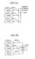
- Figs. 3a and 3bshow a broadcast/multipoint network and a point-to-point network, respectively, for use with the present invention.
- representative nodes 140a, 140b, 140care communicatively coupled with a common transmission medium 250 through individual segments 240a, 240b, 240c respectively.
- a message containing a broadcast destination address sent from one nodeis sent to all other nodes coupled with transmission medium 250.
- nodes 140d, 140e, 140fare communicatively coupled to each other by individual segments 260d, 260e, 260f respectively of transmission media and hub 255.
- Segments 240a, 240b, 240c and common transmission medium 250may be (but are not restricted to) a phone line, a power line, a wireless medium, coaxial cable, or a fiber optic medium.
- Reference to Figs. 3a and 3bshould be made with respect to the description of the embodiments of the invention as set forth below.
- Each node in either type of networkhas within it a device that permits the node to send and receive data frames in the form of electrical, electromagnetic, or optical signals.
- the deviceis conventionally a semiconductor device implementing the PHYSICAL layer of the network connectivity, and the medium access control (MAC) portion of the DATA layer of network connectivity.
- MACmedium access control
- Application header (AH) 103is appended to message 108 in the APPLICATION layer, to identify the application being executed by node 102.
- Original message 108, plus the application header AHis passed to the PRESENTATION layer, where it is again appended with a presentation layer header (PH) 105.
- PHpresentation layer header
- Such processcontinues, accordingly adding session header (SH) 107, transport header (TH) 109 and network header (NH) 111 down to the DATA layer, where the message and appended headers is encapsulated with data layer header (DH) 112 and start of frame (SOF) indicator 113.
- the DATA layeralso may add data trailer (DT)114 and end of frame (EOF) indicator 115.
- Data layer header 112may include a source address (SA) to identify node 102 sending the message, and may also include a destination address (DA) to identify the intended recipient or group of recipients.
- SAsource address
- DAdestination address
- the message with appended headers, trailers and indicatorsis then passed to the PHYSICAL layer where it is passed on to network transmission medium 106.
- the reverse processoccurs in the network stack of node 104.
- the header and/or trailer informationis stripped off as message 108 ascends the network stack.
- each layeris typically implemented as a combination of logic and memory storage that is configured to carry out the task of the layer.
- the logiccan be in the form of hardware, software, firmware, or a combination of those.
- Each layermay also be implemented using programmable gate array (PGA) technology, such as system programmable gate arrays (SPGA) and field programmable gate arrays (FPGA).
- PGAprogrammable gate array
- SPGAsystem programmable gate arrays
- FPGAfield programmable gate arrays
- each layer, or a combination of the layersmay be implemented as an integrated circuit or software program. Therefore, it should be apparent to those skilled in the art, that there are many ways in which to implement the inventions described herein.
- Fig. 2shows DATA layers 120a, 120b and PHYSICAL layers 220a, 220b for a representative pair of nodes 140a, 140b according to the invention.
- Each nodehas within it semiconductor device(s) that implement the PHYSICAL layer as well as the medium access control (MAC) and Link Layer portions of the DATA layer, such as that implemented by the Broadcom Corporation Model BCM 4210 Controller.
- the PHYSICAL layeris concerned with transmission and reception of bit stream traffic to and from the transmission medium.
- Transmitters and receiversdescribed in more detail below, form a transmission medium interface, and may be implemented as a single device or separate devices.
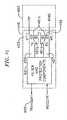
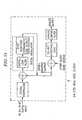
- FIG. 4ashows in block diagram form the controller aspects of the embodiment, while Fig. 4b show typical network interface device (NID) analog front end aspects of the embodiment.
- NIDnetwork interface device
- controller 300is a fully integrated MAC / PHY device that transmits and receives data (e.g., 10Mbps and above as implemented by the aforementioned Broadcom Corporation Model BCM 4210, 4211, 4413 controllers).
- Controller 300includes bus interface 310, such as a PCI or MSI bus interface for communication in accordance with well-known PC -based and/or peripheral/internet appliance architectures.
- Controller 300also includes digital PHY 320 having a FDQAM / QAM transmitter and receiver interfacing with the analog front end and MAC 330, coupling to bus interface 310 through transmit (TX) FIFO 340 and receive (RX) FIFO 350.
- Bus interface 310also has the capability of similarly communicating with other devices 360, such as a v.90 modem through v.90 modem interface or a 10/100 Fast Ethernet bus through a 10/100 Fast Ethernet interface, and their respective transmit (TX) FIFO 370 and receive (RX) FIFO 380.
- TXtransmit
- RXreceive
- NID analog front end 400connects controller 300 depicted in Fig. 4a to a transmission medium 106 such as a premises UTP wiring as depicted in Figs. 1a, 1b and 1c.
- Analog front end 400includes digital input/output (I/O) circuit 410 for transferring samples and is coupled to a transmit path and a receive path.
- Digital I/O 410includes clock 412 for driving controller 300 with a 64MHz +/- 100ppm clock generated by 64Mhz crystal 414.
- the transmit pathincludes digital-to-analog converter 420 for converting 10 bit sample data to an analog signal, automatic gain controller 425 for setting gains based upon input received by digital I/O 410, filter 430, transmit-off switch 435, and is coupled to phoneline connector 450, such as a UTP wiring RJ11 connector, through electronic hybrid 440 for buffering signals and filter/ transformer / electronic protection circuit 445.
- the receive pathincludes analog-to-digital converter 460 for sending valid sample data, variable gain amplifier (VGA) 470, filter 480 for low-pass anti-aliasing, VGA 490, and is similarly coupled to phoneline connector 450 through electronic hybrid 440 and filter/ transformer/ electronic protection circuit 445.
- VGAvariable gain amplifier
- Electronic hybrid 440 and filter / transformer / electronic protection circuit 445are connected therebetween by a plurality of transmit and receive lines (e.g.,TX, RX1, RX2) 495.
- transmit and receive linese.g.,TX, RX1, RX2
- PHY 320uses 4 MBaud QAM modulation and 2 MBaud Frequency Diverse QAM (FDQAM), with 2 to 8 bits-per-Baud constellation encoding, resulting in a PHY-layer payload modulation rate that ranges from 4 Mb/s to 32 Mb/s.
- Informationis transmitted on the transmission medium / channel in bursts.
- Each burst or physical layer frameconsists of PHY-layer payload information encapsulated with a PHY preamble, header and postamble.
- the PHY-layer payload in each physical frameis that part of the Ethernet Link Level frame that follows the Ethertype field through the Frame Check Sequence (FCS), plus a CRC-16 and a pad field for the 4 Mbaud rate.
- FCSFrame Check Sequence
- payloadrefers to the PHY-layer payload unless otherwise specified.
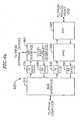
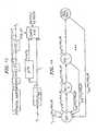
- Transmitter 500includes frame processor 510, data scrambler 520, bit-to-symbol mapper (constellation encoder) 530, and QAM /FDQAM modulator 540.
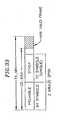
- the frame format transmitted by transmitter 500is shown in Fig.6.
- Frame format 600consists of low-rate header section 610, a variable-rate payload section 620, and a low-rate trailer 630. Some parts of the frame are not scrambled, as described below. Except where otherwise stated, all fields are encoded most significant octet first, least significant bit first within each octet. Bit number 0 is the lsb within a field.
- Header 610includes a preamble (PREAMBLE64) 612 and is defined as a repetition of four 16 symbol sequences (TRN16) that result from encoding 0xfc483084 in the order described above at 2 MBaud , 2 bits-per-Baud, with the scrambler disabled.
- the TRN16is a white, constant amplitude QPSK sequence.
- the preamblefacilitates power estimation and gain control, Baud Frequency Offset Estimation, Equalizer Training, Carrier Sense, and Collision Detection as is described in more detail below.
- Header 610also includes frame control field 614.
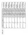
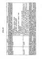
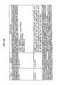
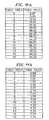
- Frame control field 614is a 32-bit field defined in the table set forth in Fig. 7. and with the bit-ordering defined above, the frame control fields are transmitted in the order shown in Fig. 8.
- the FT fieldis intended to provide a mechanism for Forward Compatibility, allowing extensions to use frame formats differing from the present embodiment.
- a next fieldis scrambler initialization (SI) field 618.
- SIscrambler initialization
- A4-bit fieldis set to the value used to initialize scrambler 520, as described below.
- a next fieldis the priority (PRI) field 620 which refers to a media access priority mechanism as described below.
- the 3 bit PHY priority value (PRI)refers to the absolute priority that a given frame will be given when determining media access, and is the value used in the MAC embodiment described below.
- Priority 7has preferential access over Priority 0.
- PRI field 620is a field carried in the PHY-level frame transmission and is intended to indicate a 3-bit PHY-level priority or class-of-service indication to the receiver link level processor for managing priority and class of service of the received frame.
- the PRI valueis not used by the receiver PHY processor.
- For stations that do not implement class-of service the PRI fieldis ignored on receive, and is transmitted set to 1.
- the next field 622is reserved (RSVD)for future use and is ignored by the receiver.
- Adjacent to field 622is payload encoding (PE) field 624 which determines the constellation encoding of the payload bits.
- PEpayload encoding
- HCS 626is an 8-bit cyclic redundancy check (CRC) computed as a function of the 128-bit sequence in transmission order starting with the FT bits and ending with the Ethernet source address (SA) bits, with zeros substituted for the as-of-yet uncomputed HCS field.
- the encodingis defined by the following generating polynomial.
- G xx 8 + x 7 + x 6 + x 4 + x 2 + 1
- the CRC value corresponding to a given frameis defined by the following procedure.
- the 8 bits of the CRC'are placed in the HCS field so that x 7 is the least-significant bit of the octet and x 0 term is the most-significant bit of the octet. (The bits of the CRC' are thus transmitted in the order x 7 , x 6 ,... x 1 , x 0 .)
- HCS 626is embedded within the protected bit-stream, it is calculated in such a way that the resulting 128-bit stream provides error-detection capabilities identical to those of a 120-bit stream with an 8-bit CRC appended.
- the resulting 128-bit sequenceconsidered as the coefficients of a polynomial of degree 127, when divided by G(x), will always produce a remainder equal to x 7 +x 6 + x + 1.
- the input bitsare unscrambled. Because all fields covered by the HCS are transmitted at 2 MBaud and 2 bits per Baud, as described below, these fields should be received correctly in many cases where the payload is received in error.
- the HCSmay be used in conjunction with soft-decision error statistics to determine with high probability whether the header was received correctly. This knowledge may be useful for optimizing the performance of ARQ and/or rate negotiation algorithms described below.
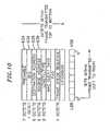
- bit fields starting with the destination address (DA) field 628 and ending with the FCS field 630are identical to the corresponding fields described in IEEE Std 802.3 as depicted in Fig. 10 and are referred to as Link-level Ethernet Frame (packet) 632.
- the bits of a PHY-level Ethernet framehave an Ethernet preamble 634 and start-frame-delimiter (SFD) 636 bits prepended to the Link-level frame, these bits are not present in the frames of the present embodiment. It is intended that IEEE assigned Ethernet MAC addresses are used for Destination Address (DA) 628 and Source Address (SA) 638.
- the Ethernet frameconsists of an integer number of octets.
- Ether-type field 640is Ethernet data field 642, FCS field 630 and cyclic redundancy check (CRC) field 644.
- CRC field 644is a 16-bit cyclic redundancy check computed as a function of the contents of the (unscrambled) Ethernet frame in transmission order, starting with the first bit of the DA field and ending with the last bit of the FCS field.
- the encodingis defined by the following generating polynomial.
- G xx 16 + x 12 + x 5 + 1
- the CRC value corresponding to a given frameis defined by the following procedure:
- CSMA/CD networksTwo difficult problems in CSMA/CD networks that use uncontrolled wiring (e.g. phoneline or powerline networks) are addressed.
- the first problemis premature end-of-carrier detection and the second problem is radio-frequency egress.
- premature end-of-carrier detectionin powerline and phoneline CSMA/CD networks, there is a need to reliably detect the end of a frame in the presence of severe channel distortion.
- the mean time required to detect the end of framefrom the actual end of frame
- reliability of detectionprobability of false alarm and probability of missed detection
- a long run of innermost pointscan clearly be a problem if an energy or matched filter detector is used to detect frame boundaries, and constant/near-constant symbol sequences (which produce tonal transmitted sequences) are problematic because they may be highly attenuated by the channel over which they travel.
- Large constellationsare used in the system to achieve high spectral efficiency, and, hence, high data rates.
- a common solution to both problemsis provided by two very simple circuits for mitigating this problem, one at the transmitter and another at the receiver.
- a simple linear-feedback shift registermay be used to generate the pseudo-random number, if that approach is chosen.
- the scrambler initialization circuiteither generates a pseudo-random N-bit number, or it increments the counter for the path over which the frame will travel, modulo-2 N . Either technique is sufficient.
- the scrambler initialization circuitinserts same N-bit value into an unscramble part of the header of the transmitted frame, so that the receiver may correctly recover the transmitted bit sequence by initializing the descrambler with the chosen value.
- Bits 15 through 18 of a shift registerare initialized with a 4-bit pseudo-random number (or per-path counter value). All other values are initialized to 1. The same value is placed in the unscrambled "SI" field of the Frame Control part of the header so that the receiver may recover the chosen scrambler initialization.
- Fig. 6 described aboveshows an example frame format which may convey the "SI” (scrambler initialization) bits to the receiver.
- Fig. 8 described aboveshows the components of the "Frame Control" field of the previous diagram in this example. All bits up to and including "SI" in the are unscrambled in accordance with the present invention. Any bits following the SI field are scrambled using this technique.
- Bits 15 through 18 of shift register 650are initialized with a 4-bit pseudo-random number. This value is placed in SI field 618 defined above in the order such that register position 15 is the MSB (bit 19 of frame control) and bit 18 is the LSB (bit 16 of frame control).
- Scrambler 520is bypassed during the preamble bit field and the first 16 bits of Frame Control. Scrambler 520 is initialized and enabled starting with the 17 th bit of Frame Control field 614.
- Scrambler 520is bypassed after the last bit of the CRC-16 644, or the last bit of the PAD field 646, if present.
- the EOF sequenceis not scrambled.
- the use of a pseudo-random initial scrambler stateresults in a more uniform power-spectral density (PSD) measured over multiple similar frames. This eliminates the problem of tones in the PSD from highly correlated successive packets.
- PSDpower-spectral density
- input frame 5010is the output of framing 510 as seen in Fig. 5 which also generates SI value 618 as seen in Fig. 8.
- Bit values of 1 5002are inserted into register bit locations 1 - 14 5004. Further bit values of 1 5006 are inserted into register bit locations 19 - 23 5008.
- SI value 618is inserted into bit locations 15,16,17,18 5009 of register 650.
- Each of the additionsare modulo 2, i.e., a bit, exclusive or, another bit, and so on.
- Input bits 5010are exclusive or'd with the output bits of register 650.
- Output bits 5012are provided to constellation encoder 530 as seen in Fig. 5., bit 1 being the most recent bit.
- the descrambler initialization circuitextracts the N bits of the "SI" field from the received frame. It then inserts the N bits into the same positions of the descrambler delay line that were initialized in the scrambler, in the same order. (Note that the descrambler and scrambler delay lines have exactly the same length, in bits.) In the example embodiment, all other bits in the descrambler delay line are set to "1". The first bit inserted into the descrambler is exactly the first bit inserted into the scrambler in the transmitter.
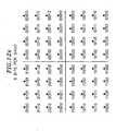
- constellation encoder 530Following scramber 520 is constellation encoder 530. All bits up to and including the Ethertype field are encoded at 2 MBaud, 2 bits per Baud. Starting with the 1 st bit following the Ethertype field, the bits are encoded according to the PE field 624, up to the last bit of the CRC-16 644, or the last bit of PAD 646 if it is present. The EOF sequence 648 is encoded at 2 MBaud, 2 bits per Baud. Constellation encoder 530 performs bit to symbol mapping. The incoming bits are grouped into N-bit symbols, where N is the number of bits per baud specified in PE field 624. The bit to symbol mapping is shown in Figs. 12a through 12g.
- the symbol valuesare shown with bits ordered such that the right-most bit is the first bit received from scrambler 520 and the left-most bit is the last bit received from scrambler 520.
- All constellations except for 3 bits-per-Baudlie on a uniform square grid, and all constellations are symmetric about the real and imaginary axes.
- the relative scaling of different constellations at a single baud rateis shown in Fig. 13.
- the constellation pointsare scaled such that the reference points have the values shown, with a minimum-distance tolerance of plus or minus 4%.
- the constellation pointsare scaled such that the outermost points have approximately equal magnitude. Symbols at 4 MBaud are transmitted at 0.707 the amplitude of symbols at 2 MBaud.
- the first 4 MBaud symboloccur 0.5 microseconds after the last 2 MBaud symbol.
- the first 2 MBaud symboloccur 0.5 microseconds after the last 4 MBaud symbol.
- Fig. 14If the number of bits in a sequence at a given encoding rate (i.e. Baud rate and bits per Baud) is not an integer multiple of the number of bits per Baud, then enough zero bits are inserted at the end of the bit-stream to complete the last symbol. The number of zero bits inserted is the minimum number such that the length of the appended bit stream is an integer multiple of the number of bits per Baud.
- the number of octets in the original input bit streamcan be determined unambiguously from the number of symbols transmitted. This is true because the maximum encoding size is 8 bits per baud, which implies that the number of zero-bits appended must always be less than eight.
- QAM/FDQAM Modulator 540complex symbols from constellation encoder 540 are input to QAM/FDQAM Modulator 540.
- QAM/FDQAM modulatorimplements Quadrature Amplitude Modulation (QAM).
- Fig. 15shows an example QAM implementation.
- the carrier frequency and transmit filtersare the same for Baud rates of 2 MHz and 4 MHz.
- a 2 MBaud signalis equivalent to an appropriately scaled 4 MBaud signal in which every other symbol is zero.
- the QAM/FDQAM Modulator used in conjunction with the present inventionis described in more detail in the pending application referenced above.
- the present inventionprovides for a Compatibility Frame format which is defined for use by HPNA V2 nodes when they are sharing the phoneline with HPNA V1 nodes.
- a Compatibility Frame formatwhich is defined for use by HPNA V2 nodes when they are sharing the phoneline with HPNA V1 nodes.
- frame 700starts with a modified V1 AID field 710, followed by a V2 symbol sequence modified to have periodic gaps 720 so that a V1 receiver will detect this signal as a series of pulses.
- the frameends with trailer 730 that includes 4-symbol V2 EOF 740 and a single pulse, EOP 750, generated by passing a QPSK symbol through the transmit path.
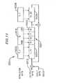
- Transmitter 800includes framing 810 implementing the compatibility mode framing described above.
- Scrambler 820is responsive to framing 810 and is identical to scrambler 520 described above in conjunction Fig. 5.
- Scrambler 820is initialized at the same point in the frame control field.
- Constellation Encoder 830Constellation encoder 830 is identical to the constellation encoder 530 described above in conjunction with Fig. 5.
- Preamble48 760is defined as a repetition of three contiguous 16 symbol sequences (TRN16) that result from encoding 0xfc483084 at 2 MBaud, 2 bits-per-baud, with scrambler 820 disabled.
- the 72-symbol headerincluding frame control field (as defined in Fig. 7) and Ethernet DA, SA, and Ethertype fields, is contained within four contiguous subframes. It is scrambled and mapped to constellation points, prior to gapping, as previously described above.
- a subframeconsists of: one non-information-bearing symbol (the lead symbol), produced by Gap Insertion block 840, and 18 data symbols (header).
- a gap of 6 2-Mbaud zero symbolsfollows each subframe of 19 non-zero symbols.
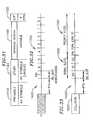
- the format of each subframe and gap for the 2-Mbaud headeris depicted in Fig. 18.
- the lead symbolOn subframes 0 and 2 of the header, the lead symbol is defined as the first symbol of PREAMBLE48 (bit sequence 00, encoded as QPSK).
- the lead symbolOn subframes 1 and 3 of the header, the lead symbol is defined as the negation of the first symbol of PREAMBLE48 (bit sequence 11, encoded as QPSK).
- the peak symbol amplitude shown in Fig. 18is defined hereinbefore in conjunction with constellation scaling. The sign of the lead symbol alternates such that the output of the QAM/FDQAM modulator is the same at the beginning of every subframe.
- Negating the lead symbol of every other subframeaccounts for the 180-degree rotation introduced by the (7-MHz carrier frequency) modulator and the odd number of symbols between the first symbols of two adjacent subframes.
- the special relationship between the carrier phase of the first symbol of the preamble and of every lead symbolis specific to the V2 compatibility mode. There are no such requirements in the V2 native mode.
- the 2-Mbaud payloadis encapsulated in subframes, consisting of: one non-information-bearing symbol (the lead symbol), produced by Gap Insertion block 840, between 1 and 18 data symbols (payload).
- a gap of 6 2-Mbaud zero symbols (silence)follows each subframe. On subframes 2*k, k > 1, the lead symbol is defined as the first symbol of PREAMBLE48. On subframes 2*k+1, k > 1, the lead symbol is defined as the negation of the first symbol of PREAMBLE48.
- the first floor [N*8/(r*18)] subframes of the payloadcontain exactly 18 information-bearing symbols.
- the last subframe of the payloadcontains the remaining payload symbols, between 1 and 18.
- the last subframeis also followed by a gap of 6 zero symbols.
- the format for all but the last of the 2-Mbaud payload subframes and gapsis identical to the header subframe and gap depicted in Fig. 18. For 3, 5, and 7 bits per baud, the lead symbol is not a valid point in the constellation encoder.
- the 4-Mbaud payloadis encapsulated in subframes, consisting of: one non-information-bearing symbol (the lead symbol), produced by Gap Insertion block 840, one zero symbol, and between 1 and 35 data symbols (payload).
- a gap of 13 4-Mbaud zero symbols (silence)follows each subframe. On subframes 2*k, k > 1, the lead symbol is defined as the first symbol of PREAMBLE48. On subframes 2*k+1, k > 1, the lead symbol is defined as the negation of the first symbol of PREAMBLE48.
- the first floor[N*8/(r*35)] subframes of the payloadcontain exactly 35 information-bearing symbols.
- the last subframe of the payloadcontains the remaining payload symbols, between 1 and 35.
- the last subframeis also followed by a gap of 13 4-Mbaud zero symbols.
- the format for all but the last of the 4-Mbaud payload subframes and gapsis depicted in Fig. 19.
- the peak symbol amplitude and the amplitude of the other symbols shown in the figureare defined above in conjunction with 4-Mbaud constellation scaling. For 3, 5, and 7 bits per baud, the lead symbol is not a valid point in the constellation encoder.
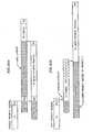
- the EOF/EOF symbol sequence for the 2-Mbaud payload caseis defined in the table set forth in Fig. 20.
- Pis the number of information-bearing symbols in the last payload subframe and M is the number of payload subframes in the frame.
- the entire EOF/EOP sequenceis encoded as QPSK at 2 Mbaud with the scrambler bypassed.
- the last symbol(similar to an V1 EOP) is used for accurate end-of-carrier timing in all V1 receivers.
- the EOF/EOP symbol sequence for the 4-Mbaud payload caseis defined in the table set forth in Fig. 21.
- Pis the number of information-bearing symbols in the last payload subframe and M is the number of payload subframes in the frame.
- the entire EOF/EOP sequenceis encoded as QPSK at 2 M-baud with the scrambler bypassed.
- the last symbol(similar to an V1 EOP) is used for accurate end-of-carrier timing in all V1 receivers.
- Modified AID Generator 850is provided.
- a modified V1 AIDis prepended to every frame.
- the modified AIDis defined as a V1 AID in which each pulse in the AID is replaced by a pulse defined below.
- the AID numberis one chosen by the sending station and conflicts are resolved by selecting a new AID number.
- the control wordalways indicates high-speed and low-power transmission.
- the use of the AID mechanism for collision detectionimplies that V2 has the same limitation on the maximum number of nodes as V1 when in compatibility mode.
- Fig. 22shows the first part of a compatibility mode frame.
- the modified AID pulseis generated by passing the first symbol of the PREAMBLE48 through the QAM/FDQAM modulator with the same initial modulator phase as the first symbol of the PREAMBLE48.
- the modified AID pulseis also used for the JAM sequence.
- QAM/FDQAM Modulatoroperates continuously from the first symbol of PREAMBLE48, as described for QAM/FDQAM Modulator 540 of Fig. 5.
- stations at a minimumare capable of transmitting and receiving 2 MBaud modulated frames in native V2 frame format.
- stationsare capable of transmitting and receiving 2 Mbaud Compatibility V2 frame format.
- Stations at a minimumare capable of transmitting all constellations from 2 bits-per-Baud to 8 bits-per Baud (PE values 1-7) and receiving all constellations from 2 bits per Baud to 6 bits per Baud (PE values 1-5).
- the R.M.S. differential transmit voltagedoes not exceed-15 dBVrms in any 2-msec window between 0 and 30 MHz, measured across a 135-Ohm load between tip and ring for any payload encoding.
- the peak differential transmit voltagedoes not exceed 580 mVpeak for any payload encoding at either 2 Mbaud or 4 M baud. Stations that are not transmitting emit less than -65 dBVrms measured across a 100-Ohm load between tip and ring.
- the electrical characteristics described below as to spectral maskapply to both the V2 native mode and the V2 compatibility mode.
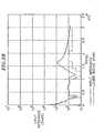
- the V2 metallic power spectral density (PSD)is constrained by the upper bound depicted in the Figs. 23a and 23b with the measurement made across a 100-Ohm load across tip and ring at the transmitter wire interface. The mask applies to all payload encodings at both 2 and 4 Mbaud.
- the resolution bandwidth used to make this measurementis 10 kHz for frequencies between 2.0 and 30.0 MHz and 3 kHz for frequencies between 0.015 and 2.0 MHz.
- An averaging window of 213 seconds used, and 1500-octet MTUs separated by an IFG duration of silenceis assumed.
- a total of 50 kHz of possibly non-contiguous bandsmay exceed the limit line under 2.0 MHz, with no sub-band greater than 20 dB above the limit line.
- a total of 100 kHz of possibly non-contiguous bandsmay exceed the limit line between 13.0 and 30.0 MHz, with no sub-band greater than 20 dB above the limit line.
- the 10 dB notches at 4.0, 7.0 and 10.0 MHzare designed to reduce RFI egress in the radio amateur bands.
- the maskis tested at PE values of 1 and 2 (2 and 3 bits/symbol), as these payload encodings result in the maximum transmitted power.
- the absolute power accuracyis +0/-2.5 dB relative to -7 dBm, integrated from 0 to 30 MHz.
- the passband ripple between 4.75 and 6.25 MHz and between 8.0 and 9.25 MHzis less than 2.0 dB.
- the magnitude of the V2 transmitter outputis upper-bounded by the temporal mask shown in Fig. 24 for a compatibility mode pulse (the symbol response of the 2.0 transmitter). The response is measured across a 100-Ohm load between tip and ring at the transmitter's WIRE interface.
- the first compatibility mode pulse in the modified AIDis exactly the transmitter symbol response.
- the transmitter C-weighted output in the band extending from 200 Hz to 3000 Hzdoes not exceed 10 dBrnC when terminated with a 600-Ohm resistive load.
- the transmitteremits no more than -55 dBVrms across a 50-Ohm load between the center tap of a balun with CMRR > 60 dB and the transceiver ground in the band extending from 0.1 MHz to 50 MHz.
- the transmitter clock frequencyis accurate to within +/-100 ppm over all operating temperatures for the device.
- the minimum operating temperature range for this characteristicis 0 to 70 degrees C. In general, a +/- 50 ppm crystal meets this characteristic.
- the R.M.S. jitter of the transmitter clockis less than 70 psec, averaged over a sliding 10-microsecond window.
- the differential noise outputdoes not exceed -65 dBVrms across a 100-Ohm load, measured from 4 to 10 MHz with the transmitter idle. There is no gain or phase imbalance in the transmitter, except with respect to constellation scaling as described above.
- the receiverdetects frames with peak voltage up to -6 dBV across tip and ring at a frame error rate of no greater than 10 -4 with additive white Gaussian noise at a PSD of less than -140 dBm/Hz, measured at the receiver.
- the receiverdetects 1518-octet frames frames encoded as 2 bits/symbol and 2 Mbaud with R.M.S. voltage as low as 2.5 mV at no greater than 10 -4 frame error rate.
- the R.M.S. voltageis computed only over time during which the transmitter is active.
- the receiverdetects no more than 1 in 10 4 1518-octet, 2 bits/symbol, 2 Msymbol/sec frames with R.M.S voltage less than 1.0 mV. Both criteria assume additive white Gaussian noise at a PSD of less than -140 dBm/Hz, measured at the receiver, and assume a flat channel.
- the receiverdemodulates frames with payload encoded at 6 bits/symbol, 2 or 4 Mbaud (if implemented),and differential R.M.S voltage as low as 20 mV (measured over the header) at a frame error rate less than 10-4 under the following conditions: (1) White Gaussian noise with PSD less than -130 dBm/Hz is added at the receiver, and (2) A single tone interferer with any of the frequency band and input voltage combinations set forth in Fig. 25. The applied voltage is measured across tip and ring at the input to the transceiver.
- the receiverdemodulates frames with payload encoded at 6 bits/symbol, 2 or 4 Mbaud (if implemented), and differential R.M.S voltage as low as 20 mV (measured over the header) at a frame error rate less than 10-4 under the following conditions: (1) White Gaussian noise with PSD less than -130 dBm/Hz is added at the receiver, differential mode, and (2) A single-tone interferer, measured between the center tap of a test transformer and ground at the input to the transceiver, with any of the following frequency band and input voltage combinations set forth in Fig. 26.
- the common mode rejection of the test transformer used to insert the signalshould exceed 60 dB to 100 MHz.
- the average return loss of the transceiver with respect to a 100-Ohm resistive loadexceeds 12 dB between 4.75 and 9.25 MHz. This characteristic applies to the transceiver powered on or in low-power mode (transmitter powered off). The average return loss with respect to a 100-Ohm resistive load exceeds 6 dB between 4.75 and 9.25 MHz with the transceiver removed from a source of power.
- the magnitude of the input impedanceis > 10 Ohms from 0-30 MHz and conforms to the lower-bound mask set forth in Fig. 27. This characteristic applies to the transceiver powered on, in low-power mode (transmitter powered off), or removed from a source of power.
- Fig. 28shows an example of the input impedance of a compliant device with a lower bound mask.
- receiver functionality 900performs the reverse of that described above for transmitter 500, namely, upon receiving a signal from 2-4 wire hybrid and performing front end processing as described in conjunction with Fig. 4b, the following occurs: QAM/FDQAM Demodulator Gap Removal, Consellation Decoding, De-scrambling and De-framing, as is well-known in the art given the above-defined transmitter functionality.
- Homenetworking MAC Layer Overview
- the HPNA V2 MACis modeled after the carrier-sense multiple-access with collision detection (CSMA/CD) MAC function of Ethernet (IEEE Std 802.3, 1998 Edition), adapted to the V2 PHY and enhanced with quality-of-service (QoS) features.
- CSMA/CDcarrier-sense multiple-access with collision detection
- QoSquality-of-service
- the MAC logical layers and functionsare depicted. Although the MAC function is an essential part of the wire interface characteristics, the system partitioning of PHY and MAC functions is implementation dependent. In particular, it is intended that the present embodiment can be implemented in an integrated PHY+MAC chip as well as a PHY-only chip that can be interfaced with a standard "MAC chip” using the Media Independent Interface (MII) described in IEEE Std 802.3-1998, clause 22.
- MIIMedia Independent Interface
- V2 devicesWhen in Compatibility Mode V2 devices transmit either V1 Format frames or V2 Compatibility Format frames depending on the destination station type.
- the MAC operation in this modeis IEEE Std 802.3-1998 CSMA/CD MAC with BEB collision resolution and no access priority.
- the MAC operationWhen in compatibility mode the MAC operation is as specified in IEEE Std. 802.3-1998, clause 4, for a MAC sublayer operating in half duplex mode at speeds of 100 Mb/s and below.
- the timing parameters to be used in Compatibility Modeare in accordance with the V1 PHY Specification, Version 1.1.
- the MACIn compatibility mode the MAC times the inter-frame gap from the de-assertion of the carrier sense signal, CAR_SENS.
- the timing of CAR_SENS relative to the wire interfaceadheres to the timing specified in HPNA V 1 PHY Specification rev 1.1, clause 3.3.
- An implementationmay have different individual CAR_SENS/MAC timing parameters provided the overall timing at the wire interface is the same as CAR_SENS/MAC with the parameters specified. Further, In compatibility mode the detection of collisions is as specified in HPNA V1 PHY Specification rev 1.1, clause 2.5.3, with a JAM signal emitted as specified in clause 2.5.4. ACCESS ID values are maintained as specified in clause 2.5.5.
- each station on an V2 network segmentwhen not in Compatibility Mode, executes the V2 MAC function to coordinate access to the shared media. Switching between Compatibility Mode and V2 native mode is described hereinbelow.
- the MAC timing parameters for V2 Modeare also defined below.
- the Carrier Sense Multiple Access / Collision Detect (CSMA/CD) media access methodis the means by which two or more stations share a common transmission channel. To transmit, a station waits (defers) for a quiet period on the channel (that is, no other station is transmitting) and then sends the intended message modulated as per the PHY characteristics.
- the transmission deferralis ordered by up to eight priority levels, implementing absolute priority among stations contending for access. If, after initiating a transmission, the message collides with that of another station, then each transmitting station ceases transmission and resolves the collision by choosing a Backoff Level and defers to other stations that have chosen a lower Backoff Level.
- the distributed algorithm for choosing Backoff Levelguarantees that the access latency is tightly bounded.
- a transceiver functional block diagram of an embodiment of the present inventionwhich includes transmit functionality portion 500, counterpart receive functionality portion 900, V1 compatability transmit and receive functionality portions 910, 920, MAC functionality portion 1000 for both V1 and V2 modes, and 2 - 4 wire hybrid portion 930.
- MAC 1000includes carrier sense functionality portion 1100, collision detection functionality portion 1200, and CSMA/CD collision resolution/rx frame synchronization functionality portion 1300.
- Carrier Sense 1100detects the starting and ending times of a valid frame transmission on the wire. This is used to determine when frames are present on the channel/transmission medium, as well as being used to determine the presence of a Backoff Signal in a Signal Slot.
- Collision Detection 1200detects the presence of a valid frame transmission from some other station during an active transmission, and for all stations, including non-transmitting stations, detects the received fragment that represents a transmission truncated by a collision.
- Collision Resolution 1300implements the distributed algorithm that controls backoff. Although the performance of the blocks in the MAC function are implementation dependent, certain minimum performance requirements are needed to ensure interoperability and compatible sharing of the channel and are now described in more detail.
- a transmitted Valid CS Framewill be affected by various signal impairments when seen by any receiver.
- a Valid CS Frame at the transmitter wire interfaceconsists of: (1) A sequence of symbols whose duration is equal to or greater than 92.5 microseconds (TX_FRAME minimum) duration, but less than the maximum described below; (2) the first (64+16+24+24+8) symbols of which modulated at the Base Rate (2 MBaud QPSK, 2 bits per symbol), where the initial 64 symbols consist of the preamble sequence 1110, where the next 64 symbol sequence (other) 1120 is unique to the transmitting station, and where the next 8 symbols are the (likely non-unique) bits of the Ethertype field; (3) an arbitrary Minimum Signal 1140, defined as a sequence of symbols whose R.M.S.
- a Valid Collision Fragment at the transmitter wire interfaceconsists of: (1)a sequence of symbols of 70.0 microseconds (CD_FRAG) duration; (2) consisting of (64+16+24+24+8) symbols modulated at the Base Rate (2 MBaud QPSK, 2 bits per symbol), where the initial 64 symbols consist of the preamble sequence, and where the next 64 symbol sequence is unique to the transmitting station, followed by 8 more symbols; (3)4 symbols of the EOF sequence; (4) a trailing transient, whose peak voltage does not exceed 0.1 % of the absolute peak transmitted voltage across a 100-Ohm load at the WIRE interface at any point > 5 microseconds after the last transmitted symbol of the EOF; and (5) a gap of at least CS_IFG + CD_FRAG microseconds from the first symbol of the PREAMBLE64 of the Valid Collision Fragment to the first symbol of the BACKOFF20 signal in the first Backoff Signal Slot (if present), measured at the transmitter's wire interface.
- CD_FRAG70.0
- the Inter-frame Gapis 29.0 microseconds (CS_IFG), where the gap is defined at the points at which the previous frame drops below 50% of its peak and the current frame rises above 50% of its peak. Timing of subsequent transmissions following a Valid CS Frame or Valid Collision Fragment are based on a MAC timing reference, established by the receiver.
- time following a transmission TXis divided into slots: (1) an Interframe Gap (IFG)1400; (2) three Backoff Signal Slots 1500 (following collisions 1600); and (3) 8 priority slots 1700.
- IFGInterframe Gap
- the MACis synchronized and the slot timing is defined by the rules for valid transmissions as set forth above.
- priority slot 0there may be an arbitrarily long period with no transmissions followed by one or more stations attempting transmission. In this latter case the MAC is unsynchronized.
- TX_ONmicroseconds
- CS_RANGEmaximum-amplitude Valid CS Frame over a range of 0 to at least 38 dB (CS_RANGE) flat-channel insertion loss and additive noise with a flat PSD of -140 dBm/Hz at the receiver with a missed frame rate of less than 10 -4 and a premature end-of-frame declaration rate less than 10 -4 .
- the false carrier detection rateis no greater than 1 per second.
- CS_DEFER12 microseconds
- the V2 embodimentcan be used for carrying media streams, such as video and audio (as described in more detail below).
- a priority mechanismis implemented to allow higher layers to label outgoing frames with priority, and guarantee that those frames will have preferential access to the channel over lower priority frames.
- the access priority method implementedis to delay transmissions to a slot beyond the minimum inter-frame gap, based on the priority level of the frame waiting to be transmitted. Referring back to Fig.32, slots are numbered in decreasing priority, starting at priority 7. Higher priority transmissions commence transmission in earlier slots and acquire the channel without contending with the lower priority traffic.
- a station's Priority Slotis based on the PHY priority number associated with the frame ready for transmission (TX_PRI), as determined by the network stack and communicated to the MAC.
- the stationuses any slot with a number less than or equal to TX_PRI, normally the slot numbered exactly TX_PRI.
- the Priority Slot widthis 21. ⁇ microseconds (PRI_SLOT). No station transmits in a Priority Slot numbered higher than the TX_PRI assigned to the frame being transmitted.
- the TX_PRI valueis the priority the MAC uses to schedule transmission and is the value present in the PRI field of the frame header. This value is determined by a higher layer in the network stack.
- the PRI fieldis used to transport the priority label from source to destination, to assist the destination in managing the receive queue.
- priority 0the default "best effort” priority
- the PHY priority mechanismis strict priority (as opposed to schemes which allocate lower priorities some minimum percentage of network capacity) - higher priority traffic always defers lower priority traffic. Higher priority traffic will be limited by admission control or other Link Layer policy mechanism to prevent over-subscription.
- Two or more stationsmay begin transmitting in the same Priority Slot following the IFG period. All stations monitor the channel to detect the colliding transmissions of other stations. Colliding frame(s) will be received over a channel with impairments. Fig. 35, shows length of collisions and non-collisions. Passive stations can detect collisions by observing the length of transmission fragment and the validity of the received PREAMBLE64.
- a Valid CS Frameis guaranteed to have a unique symbol sequence within the first 128 symbols (which are transmitted at Base Rate).
- the Ethernet MAC Source Address (SA)is used to guarantee uniqueness. That field is scrambled, but the [scrambled SA, SI] tuple will be unique. SI is the 4-bit scrambler initialization field, as described above.
- a stationAfter detecting a collision a station continues to transmit through the Ethertype field followed by an EOF sequence (symbol 139) and then cease transmission. Thus, a station detecting a collision will cease transmission no later than 70.0 microseconds (CD_FRAG) after the beginning of the frame as measured at the wire interface.
- the minimum size of a Valid CS Frameis 92.5 microseconds (TX_MIN). No jam signal is transmitted on collisions.
- Passive stations, that are not transmittingmonitor the length of Carrier Sense events and generate a Collision Fragment indication to the Collision Resolution function if the duration of carrier is less than 92 microseconds (CD_THRESHOLD). Stations do not recognize carrier events shorter than 32.0 microseconds (CD_MIN) as collisions.
- All transmitting and passive stationsare capable of detecting the collision of any maximum-amplitude Valid CS Frame transmission received over a range of 0 to 36 dB (CD_RANGE) flat-channel channel insertion loss and additive noise with a flat PSD of -140 dBm/Hz at the receiver with a missed-collision error rate of less than 10-4 and a false collision error rate of less than 10 -3 , where the origin of the colliding frame is offset relative to the first symbol of the transmitted frame anywhere from earlier by up to 12 microseconds (CD_OFFSET_EARLY) to later by up to 15 microseconds (CD_OFFSET_LATE).
- CD_OFFSET_EARLYmicroseconds
- CD_OFFSET_LATEthe probability of detected and undetected errors in the payload data is enhanced, so Collision Detection implementations are biased towards false collision errors, which are more innocuous.
- a collisionoccurs when two or more stations are active with ready frames and are contending for access to the channel at approximately the same time. Generally, collisions are between frames at the same priority level.
- a distributed collision resolution (CR) algorithmis run which results in stations becoming ordered into Backoff Levels where only one station is at Backoff Level 0 and can therefore acquire the channel. After the winning station completes its transmission, all stations reduce their Backoff Level by one if it is greater than zero, and the new station(s) at Backoff Level 0 attempt transmission. All stations, even those with no frame to transmit, monitor the activity on the medium. Also, the collision resolution cycle is closed, so that stations that did not collide are not allowed to contend for access to the medium until all stations that collided have transmitted one frame successfully or have forgone the right to transmit their waiting frame.
- the Backoff Level countersare initialized to 0.
- the priority level of a collisioncan be inferred from the priority slot where the collision occurs.
- three special Backoff Signal slotsSO... S2 are present before the normal sequence of priority contention slots occurs. Signal slots only occur after collisions, they do not follow successful transmissions.
- Each active stationpseudo-randomly chooses one of the slots, and transmits a Backoff Signal. More than one station can transmit a Backoff Signal in the same slot.
- the active stationstransmit Backoff Signals to indicate ordering information that determines the new Backoff Levels to be used. All stations (even those without a frame ready to transmit) monitor collision events and the Backoff Signal slots to compute the Backoff Level.
- an active stationsees a Backoff Signal in a slot prior to the one it chose, it increases its Backoff Level.
- Those stations at Backoff Level 0ones that are actively contending that saw no Backoff Signals prior to the one they chose, remain at Backoff Level 0 and contend for transmission in the priority slot equal to TX_PRI that immediately follows the Backoff Signal sequence.
- TX_PRIthat immediately follows the Backoff Signal sequence.
- Stations with higher priority waiting framesmay pre-empt the collision resolution by transmitting in a higher-priority slot. All stations, even those not contending for access to the wire, also maintain a Maximum Backoff Level (MBL) counter per priority, which is incremented for each Backoff Signal seen and decremented when a successful transmission occurs.
- MBLMaximum Backoff Level
- the MBLis non-zero whenever a collision resolution cycle is in progress.
- BLis initialized to contents [MBL], otherwise BL is initialized to 0. This ensures that all currently active stations gain access to the channel before stations can re-enter the waiting queue.
- the BACKOFF20 signalis a symbol sequence consisting of 16 symbols of the preamble sequence (TRN16) transmitted, followed by the 4 symbol EOF sequence. Detection of the BACKOFF20 signal(s) in a Backoff Signal slot must be possible even if more than one station selects the same slot.
- Stationsimplement saturating 4-bit BL and MBL counters.
- the width of the Signal Slotis 32 microseconds (SIG_SLOT).
- Stationsimplement the MAC function with collision resolution whose behavior matches the procedural model described below.
- the procedural modeluses a pseudo-code modeled after Concurrent Pascal. IEEE Std 802.3 1998 Clause 4.2.2 provides an overview of this pseudo-code.
- the code set forth belowmodels three independent concurrent processes (Deference, Transmitter, Receiver), which interact through shared variables.
- the Deference processis driven by the detection of transmissions on the channel, and times the boundaries for Signal Slots and Priority Slots.
- the shared variable current Prioritysignals the Transmitter process when a transmission slot exists.
- the Link-level frameconsists of the DA through FCS fields, prior to the PHY-level frame encapsulation. All V2 stations transmit link-level frames with a minimum of 64 octets. The payload field of link-level frames smaller than minFrameSize is padded with any value octets appended after the supplied payload to make the frame minFrameSize long.
- the maximum standard Ethernet frameis 1518 octets, but some V2 link-layer encapsulations may add additional octets.
- All V2 stationsare able to transmit and receive link-level frames with up to 1526 octets.
- No V2 stationtransmits link level-frames with more than (PE+1)*1024 octets for 2 MBaud and not more than (PE-7)*2048 octets for 4 MBaud.
- a V2 stationdefaults the maximum length frame it will send to a given DA to 1526 octets until it can determine that the receiver can support larger transmission units (e.g. by use of the CSA announcement of CSA_MTU as described below with regard to Link protocols. These maximums establish an upper bound on the duration of a given transmission and an upper bound on the maximum frame size that receivers must accommodate.
- Homenetworking Link Layer Overview
- Link control functionsare implemented: (1) Rate Negotiation; (2) Link Integrity; (3)Capability Announcement; (4) Limited Automatic Repeat reQuest (LARQ).
- These link functionsuse control frames to carry protocol messages between stations.
- V2includes a standardized mechanism for Link Layer network control and encapsulation.
- Control framesare data link layer frames that are identified by IEEE assigned Ethertype value (0x886c designated for the Assignee of the present application) in the Type/Length field of the frame, and further distinguished by individual sub-types.
- the link control entitiesmay be implemented in hardware or driver software. Link Control frames are not seen by layer 3 (IP) of the network stack, and are not bridged between network segments.
- IPlayer 3
- Minimal Link Protocol Support Profile for HPNA V2 Link Protocols embodiments of the present inventionallow less complex implementations of the HPNA V2 characteristics. While each of the four control protocols serves an important function in the operation of the network, it is possible to implement minimal support for CSA and LARQ that is compatible with fully functional implementations and does not detract from the overall performance of other stations.
- Minimal Profilewill be used hereinbelow. Full support of all the link protocols, called the Full Link Protocol Support Profile or Full Profile for short, is assumed unless Minimal Profile is explicitly mentioned.
- Figs. 37 and 38there are two basic formats for a Link Control Frame, a long subtype and a short subtype.
- the long subtype formatis provided for future specified control frames where the amount of control information exceeds 256 octets.
- the control and encapsulation frames described hereinuse the short subtype format.
- the Link Control Frameis converted into a physical layer frame by adding Preamble, Frame Control, CRC-16, PAD and EOF as described above.
- the SSVersion fieldis recommended for all protocols using the Short Form Link Control Frame header, and specifies which format version of the control information is used. This allows future extension of each SSType. SSLength is checked only to ensure that enough control information is present. New, backwards compatible, frame formats may contain additional fixed data fields, but will always contain the fixed fields specified in earlier formats, so protocol implementations simply use the latest version that is less than or equal to SSVersion.
- the Next Ethertype fieldis implemented for all SS headers. Among other things, it supports backward compatibility by enabling receivers to always strip short format link layer headers.
- the frameis a basic control frame and is dropped after processing the control information it contains.
- the Next Ethertypeis always the last two octets of the control header.
- the position of Next Ethertype in the frameis determined using the SSLength field in order to ensure forward compatibility.
- V2 receiversare able to remove at least one encapsulating header with an unknown subtype from any received data frame. Future embodiment versions may require the processing of multiple headers, such as might occur if a Rate Request Control Frame were inserted into (piggybacked on) a regular data frame with a LARQ header.
- the header and trailer for standard Ethernet framesare cross-hatched in Fig. 37, in order to highlight the formats of the control information frames.
- the MSByte of the fieldis the first octet of the field to be transmitted, with the LSBit of each octet transmitted first. Subsequent bytes within a field are transmitted in decreasing order of significance. When subfields are pictured in the figures, the ordering shown is decreasing significance from the top to the bottom of the figure.
- the carrier sensorfor example carrier sense 1100 of Fig. 30, consists of two components: one which detects the start of frame and one which detects the end of frame.
- the carrier sense circuittakes an input from the medium access controller (MAC), which forces reset.
- MACmedium access controller
- the decision logicdepends on the state information, per the table set forth in Fig. 39.
- Lwill be 2, 4, 8, or 16.
- the complex samplesare generated by a filter which performs nearly a Hilbert transform on its input.
- the input samplesare band-pass and notch filtered to attenuate noise and interference while minimally reducing the channel capacity.
- the circuit embodiment in accordance with the present inventionconsists of a special filter whose coefficients are matched to the preamble symbol sequence and a detector which performs near-optimal detection of the preamble in the presence of additive white Gaussian noise.
- the filter/detectoris not a true matched filter detector in the textbook sense, because: (1)the filter is not matched to the input sample sequence but, rather, the input symbol sequence, and (2)the filter includes additional delay elements to minimize the probability of a false trigger immediately before the correct start of burst position.
- start of preamble detectorsThere are two possibilities for start of preamble detectors: a simple, low-delay detector and a more complex, robust detector. Both are included in the description of the embodiments below.
- the circuit in accordance with the present inventionis designed to operate in networks in which the insertion loss between any two points is less than 38 dB. Since the carrier sense function must operate before the gain can be adjusted, the minimum SNR at which the system must operate is calculated as: SNR > P SNR 10 ⁇ bit ⁇ ADC ⁇ P A R 4 ⁇ QAM preamble ⁇ L insert
- PSNRis the peak signal to noise + distortion for the analog-to-digital converter (ADC), which is about 60 dB.
- ADCanalog-to-digital converter
- the worst-case PAR for the preambleis about 10 dB.
- the start of preamble detection functionmust operate reliably down to about 12 dB SNR.
- Reliable operationis defined as no more than one missed detection in 10 5 actual frames and no more than one false alarm in 10 seconds in additive white Gaussian noise (no valid frames). Missed detection performance should improve with increasing SNR. Reliable detection tends to require longer filters and more averaging. Unfortunately, increasing reliability has the side-effect of increasing the medium access slot times.
- the start of preamble detectormay consist of two matched filter detectors.
- Oneis a "first-pass", short matched filter detector which is used for determining slot boundaries (to minimize the slot duration).
- the seconduses a matched filter which spans one entire copy of the training preamble, for reliable detection.
- the first-pass detectorproduces a "transmit hold-off" signal, which is used only to inhibit transmission until the second-pass (longer filter) detector makes a more reliable determination of medium state.
- the second-pass start of preamble detectoruses a matched filter with averaging and an average power estimate to determine the start of frame within +/- 1-microsecond intervals. Therefore, in accordance with the present invention, both a circuit in which the low-delay and robust detectors are used in conjunction and also a circuit in which only the robust detector is used is provided.
- the low-delay detectoruses a filter matched to the first n symbols of the preamble.
- r, r+1, q, etc.are merely examples in one particular embodiment, and the invention is not limited to any particular datapath widths.
- "j"is the sample (time) index in Fig. 40. Note that, because the preamble consists of only QPSK symbols, no multiplications (only additions and subtractions) are required.
- the output of the MA blockis computed as max(x i , x q ) + 1 ⁇ 2 * min(x i , x q ), where x i is the in-phase component of the complex sample and x q is the quadrature component, with rounding.
- the (roughly) equivalent moving averagewould sum the 16 samples, then shift the result right by 4 bits with rounding. Therefore, in accordance with the present invention a circuit is provided that enables rapid detection of the start of a burst using the first n symbols of the preamble and no multiplication operations. This allows delineation of medium access slot boundaries.
- the robust detectoruses a filter matched to the first k*n symbols of the preamble, described above.
- the thresholds depicted in the figureare considered “good values", but are not a requirement of the invention.
- the thresholdsare adjustable.
- the delays between the delays between the h match path and the power estimation path, D v1 and D v2are used to account for the differences in group delay between the paths. If these delays are not included, the probability of a false trigger slightly before the beginning of a frame may be increased. Note that, because the preamble consists of only QPSK symbols, no multiplications (only additions and subtractions) are required.
- the output of the MA blockis computed as max(x i , x q ) + 1 ⁇ 2 * min(x i , x q ), where x i is the in-phase component of the complex sample and x q is the quadrature component, with rounding.
- the output of the matched filter in this one embodimentsaturates at r-1 bits twos-complement, but other outputs are possible within the scope of this invention.
- the "matched filter” in this detectoris not a true "matched filter”, since it is not matched to the expected input sample sequence: there is no a priori knowledge of the wire network's impulse response. Therefore, in accordance with the present invention a circuit is provided that enables very robust detection of the start of a burst using the first k*n symbols of the preamble and no multiplication operations. This enables efficient channel estimation (fewer coefficients), reliable detection of the start of a burst in SNRs as low as 3 dB, and accurate automatic gain control.
- Fig. 42specific operational aspects of the start of frame detection are described in more detail.
- One aspectis the start of frame detection.
- In upper portion 3010the first stages of carrier sense / start of preamble detection is shown.
- In lower portion 3012the remaining stages are shown. Accordingly, the carrier sense processing starts at the upper left portion of Fig. 42 and ends at the lower right portion of Fig. 42.
- Input 3014has r bits, which in a preferred embodiment is at 8Msamples/sec.
- Matching filter/correlator 3016receives the r bits, and filters the input using filter coefficients which are a time-reversed sequence copy of the preamble sequence.
- the output of filter 3016is provided to magnitude approximator 3018 and squaring function 3020.
- Magnitude approximator 3018provides a real output for which on one squaring operation is needeed, avoiding the need for a multiplier function.
- the output of squaring function 3020is input to low-pass filter 3022.
- Low pass filter 3022smoothes the input thereto and provides output Z j .
- At input 3014 ris also fed into an energy detection computation where magnitude approximation 3024 is performed, then a squaring operation 3026, then a longer duration low-pass filtering 3028, and then performing a low-pass filtering operation 3030 comparable to that of low-pass filter 3022, providing an output zh j .
- Z jis then put through logarithm function 3032 to allow measuring of ratios avoiding division operations.
- Z hjis similarly put through logarithm function 3034.
- Two testsare performed during the carrier sense computation at compare functions 3036 and 3038. Where inputs A and B respectively are compared based upon a threshold, e.g., 9dB threshold input into compare function 3036 and 3dB threshold input into compare function 3038. In other words a calculation is performed to determine if A - B is > than the threshold.
- Delays 3040, 3042,3044are provided between the logarithm functions and the compare functions. In essence, with regard to the Z j processing of portion 3012, the smoothed low-pass filtered output of the matched filter is compared with a delayed copy of itself, as provided by delay 3040.
- delay function 3044is applied to the output of logarithm function 3032 providing a slightly delayed input to compare function 3038.
- delay function 3042 and maximizing function 3046is applied to the output of logarithm function 3034 to provide a sampled maximum to avoid getting a false trigger. Therefore compare function 3038 compares that smoothed low-pass filtered output is greater than the Z hj output of the energy detector.
- the output of comparator functions 3036 and 3038is then provided to AND function 3040, a match if both inputs are true and a no match if one is not true.
- low-pass filtering function 3022(and its counterparter function 3030) is depicted in more detail and is considered an implementation of an Infinite Impulse Response (IIR) filter.
- IIRInfinite Impulse Response
- Left by 4 bit shift 3042is applied to input signals N, the output of which is applied to adder 3044.
- the output of adder 3044is provided to round to the nearest integer function 3046 which provides a signal which is sent to right by 4 bit shift 3048, then to one clock delay 3050.
- the output of one clock delay 3050is provided to left by 4 bit shift 3052, the output of which is applied to subtractor 3054 along with an output of delay 3050.
- the value of the recursive pathis then set thereby.
- Rounder 3056takes the N+8 signal from adder 3044 and provides its output to Right by 8 bit shift 3058 to provide N bits output.
- filter 3028is a moving average filter which takes N inputs sums them together and divides the sum by N.
- end of frame detectionis complicated by the need to avoid prematurely detecting the end of a burst and the possibibility that there can be: (1) a long run of innermost constellation points in a large transmitted constellation - in this case, the receiver attempting to determine the end of frame may be unable to demodulate the signal because the SNR is not sufficient (the innermost points are lost in noise);and (2) a long run of the same, or nearly the same, constellation point - in this case, a channel with a null in exactly the wrong place can substantially attenuate this symbol sequence.
- the end of frame detectoruses a short filter matched to the last n symbols of the frame (the end-of-frame delimiter), above.
- the inputis complex at L times the nominal transmitted symbol rate.
- the matched filterin this case consists of L*n coefficients, which are the n "end-of-frame" marker symbols, complex-conjugated, time-reversed, and upsampled by L with zero-filling.
- the inputis applied to the matched filter, and the output of the filter is passed into a magnitude approximation circuit.
- the output of the magnitude approximation circuitis squared and applied to the same one-pole low-pass filter or moving average filter described in the sections above.
- the averaged outputis then applied to the same approximate 10*log10(.) function. This output can be called z(j), where j is the sample index.
- the first criterion for detecting the end of a frameis: z j - z j - L * p ⁇ thd_off
- a reasonable value for thd_off in one embodimentis 8 dB.
- a reasonable value for L*p in microsecondsis 12. Therefore, in accordance with the present invention other values of thd_off and L*p within scope the scope of the present invention. If this test passes, the z(j-L*p) value is stored, and the same test is applied on the L*k*n subsequent samples, replacing z(j-L*p) with this stored value. If k1 of these tests pass, the end of frame is declared.
- the end-of-carrier detector described hereinis capable of determining the end of a received frame within a +/- 2 microseconds interval, and can be considered as a circuit that performs two tests in order. Therefore, in accordance with the present invention a circuit is provided that enables rapid detection of the end of carrier using the last n symbols of the burst and no multiplication operations. This enables efficient use of the medium by keeping medium access slots short.
- the delayed value r j-L*pis stored.
- the stored valueis compared with the non-delayed r j value. If the thd_off threshold is exceeded on k1 of these samples, the end of the frame is declared.
- One particular embodimentrequires that the thd_off threshold be exceeded on all L*k*n samples. The state diagram shown in Fig. 44 depicts such a case.
- a framemay not be terminated until a specified point after the start of the frame. In one embodiment, this point is the end of the Ethertype field of an encapsulated Ethernet frame.
- the present inventionincludes a timer to ensure that the device does not remain in the BUSY state indefinitely.
- the present inventionfurther includes the ability to detect a third-party collision any time the time between the second-pass start-of-preamble detection and the end-of-frame detection is less than a specified duration threshold.
- a "third-party collision"is one in which the detecting station was not a transmitter.
- An embodiment of the inventionoptionally can include a dB function implemented with two 1-entry look-up tables, a coarse 10*log10(.) table and a fine 10*log10(.) table.
- the tablesinclude unsigned values with m0 fractional bits.
- An example embodimentcould be described by the tables set forth in Figs. 45a and 45b, showing coarse dB table values and fine dB table values, respectively.
- the algorithmis:
- Fig. 43it should be noted that the path from r input to match/no match output is similar to the correlator path in Fig. 42 without the energy detection path. Since at the end of the preamble there are four contiguous symbols of the training preamble. Therefore, the matched filter is run against the entire frame looking for peaks. Towards the end of the frame there will be a small spike and dropoff.
- the flow in Fig. 43provides a tentative match/no match decision, similar to that of the correlator path of Fig. 42 The decision is tentative to avoid premature truncation of the frame.
- a state machineas depicted in Fig. 44, is provided taking in the tentative match/no match decision as shown in Fig. 43 As described above, Test 1 is match/no match. If out of Test 1 the decision is yes, the state proceeds to Test 2, 0. When going from Test 1 to Test 2, 0 the last value of peak detected is latched. Then every subsequent sample is compared against the latched value. If after a number of comparisons it is determined that the signal is greater than the threshold value, the end of frame is determined to be detected.
- the logarithm functions 3032 and 3034 as described abovecan be implemented using the index and values set forth in Figs. 45a and 45b.
- the collision detector design for networking on phone linesis complicated by the need to detect collisions even when the line input impedance changes on the time scale of a transmitted frame.
- Line input impedance changesoccur with telephone hook-switch transitions, keying, and addition/deletion of devices from the network.
- echohybrid leakage
- the collision detector circuit in accordance with the present inventionincludes three functional aspects: (1)a channel estimator, the concepts of which are described in co-pending application No. 09/585,774, entitled “Method and Apparatus for Efficient Determination of Channel Estimate and Baud Frequency Offset Estimate", (2) a noise floor estimator, and (3) a unique field match (either SRC or SI+SRC or SRC+DST or SI+SRC+DST).
- a sequence bis defined as the 16 symbols set forth below.
- the preamble sequenceis generated as four sequential copies of the 16-symbol sequence b defined above.
- Channel estimation for the purpose of detecting collisionsis performed on either the first, second and third copies of the preamble and/or on the second, third, and fourth copies of the preamble.
- the characterization signalis the part of the received signal used for channel estimation. This signal is defined as the second and third or third and fourth copies of preamble in the received signal. The start of this signal at the receiver input interface is found by simply waiting a fixed time interval after the start of transmission (to account for fixed propagation delays). Referring to Figs. 46 a - 46c, the quantities described above are shown, assuming that the characterization signal is the third and fourth copies of the preamble sequence.
- a method for computing a complex channel estimate sampled at four times the symbol frequency of the preamble signalis provided.
- the complex input signalis also sampled at four times the symbol frequency of the preamble signal.
- Brepresent the matrix of preamble symbol values, upsampled by four and zero-filled:
- B Hb 0 * 0 0 0 b 1 * 0 0 0 ... b 15 * 0 0 0 0 b 0 * 0 0 0 b 1 * 0 0 ... 0 b 15 * 0 0 0 0 b 0 * 0 0 0 b 1 * 0 ... 0 0 b 15 * 0 0 0 0 b 0 * 0 0 0 b 1 * ... 0 0 b 15 * 0 0 0 0 b 0 * 0 0 0 b 1 * ... 0 0 0 b 15 * b 15 * 0 0 0
- ha complex 64-sample channel, sampled at 4 times the symbol rate.
- hh 0 h 1 ⁇ h 62 h 63
- the noise floor estimateis computed over the 2 nd and 3 rd copies of the training preamble and, also, over the 3 rd and 4 th copies of the training preamble.
- Two noise estimatesare computed because a colliding signal that is received more than 16 symbols before or after the start of transmission will corrupt either the second or the last copy of the training preamble. If, for example, only the 3 rd and 4 th copies of the training preamble were used, a colliding signal received more than 16 symbols after the start of a transmission could result in an over-estimated noise floor and a possible failure to detect the collision.
- S 0 ..S 15are the symbols of the training white training preamble subsequence (in order), and "*" denotes complex conjugation.
- (A H . A) -1is the 64x64 identity matrix (I 64 ) multiplied by the constant 1/(2*L tm ).
- L tmis 16 (symbol intervals).
- a method and apparatusfor the computation of the variance of each noise estimate.
- roundingis used in the right shift (of 7 bits); the output is a 19-bit quantity.
- any datapath widthmay be used.
- the resulting value ⁇is then clipped to be within ⁇ low and ⁇ high (the low and high noise points).
- the last aspect of the collision detectionis a unique field match.
- a transmittersends bursts which have a unique source (“SRC") address.
- SRCunique source
- header fieldswhich may be useful in a unique symbol template.
- SRC and DSTSRC and destination address
- SIsubscriber initialization
- SRC and DST fieldsSRC and DST fields
- SI and SRC fieldsmay be used.
- the SRC fieldis included in the template. Referring back to Figs. 6 and 8, the transmitted burst (frame) format is illustrated.
- the SRC sample template(as distinguished from the SRC symbol template) is a sequence of sample values at four times the symbol rate (T/4) which spans the 24 symbols (12 bytes) of the source address and 4 additional symbols of "guard” following the SRC field.
- the "guard” portionaccounts for the precursor of the channel impulse response. If only the SRC field is considered unique (as in the preferred embodiment), the SRC sample template is computed as the linear convolution of the 9 th symbol of the DST field through the four symbols following the SRC field with the channel estimate. Other sample templates are possible, including any which are generated as the linear convolution of a unique symbol template and the channel estimate.
- the channel estimateis computed either from the 2 nd and 3 rd or from the 3 rd and 4 th copies of the preamble, as described above.
- the linear convolutionis computed in three pieces, and the three components of the template are summed to produce the result.
- the templateis built in the following order.
- an analog-to-digital convertersufficient to meet the dynamic range requirements of the signal propagation path
- a lower- precision ADCmay often be used in conjunction with a variable-gain amplifier.
- the dynamic range requirementsare large (often greater than 60 dB), because the path propagation loss can vary between 0 dB and 40 to 70 dB.
- a very large and expensive ADCwould be required. Therefore, designers often choose a lower-precision ADC with a variable-gain amplifier and some control circuit.
- a circuitwhich estimates the required gain from a carefully-designed preamble at the start of a burst (packet).
- a preamble of M*N symbol durationis presupposed.
- the preambleis structured so that M identical copies of an N-symbol subsequence are transmitted sequentially.
- Each N-symbol subsequencehas the property of being spectrally white (i.e. nonzero cyclic autocorrelation at only one of the N possible lag values).
- the start of a burst (packet)is detected at the receiver. This function is usually referred to as "carrier sense”.
- the circuit set forth hereintakes a binary start-of-frame/no-start-of-frame indication from the carrier sense.
- the circuit in accordance with the present inventionhas two subcircuits. The first estimates the received signal power over an N-symbol window. This subcircuit runs continuously. The second estimates the required gain to maximize signal-to-noise ratio, given the power estimate, and the binary indication from carrier sense. It runs only after carrier sense has indicated the start of burst, and it ceases operation after it computes a gain code, until the next start of burst indication.
- the input to the power estimation circuitis a k-bit received signal magnitude value. This value is the output the ADC with little or no frequency-selective (e.g. low-pass or band-pass) filtering.
- the power accumulatorwhich is 2*k+log2(L*N) unsigned bits, is initialized to zero.
- Nis the number of symbols in one copy of the preamble
- Lis the ADC oversampling factor (sampling frequency divided by symbol frequency).
- the oversampling factor Lis chosen to be sufficiently-large to avoid aliasing.
- the square of each new k-bit magnitude value ( nk )is added to the accumulator. No values are subtracted from the power accumulator.
- One commercially-available embodimentprovides a control range of 22.5 dB for the variable second-stage amplifier with a step size of roughly 0.75 dB, but many other control ranges and step sizes are possible.
- the programmable back-off valueallows fixed gain variations due to particular implementations and also allows variations in the peak-to-average ratio of the received signal to be tolerated by this circuit without unacceptable saturation of the receiver.
- the first programmable table, rough_gain_tableis a r0-entry by 10-bit array of codes mapping to very coarse gain values. In one embodiment, it is an 8-entry table with 8-bit values corresponding to gain values of ⁇ 0, 3, 6, 9, 12, 15, 18, 21, 24 ⁇ dB.
- the second table, fine_gain_tableis r1-entry by II-bit array of codes mapping to a refinement of those coarse values.
- One embodimentmight use a 4-entry by 8-bit array of codes mapping to gain values 0.75 dB, 1.5 dB, 2.25, and 3 dB.
- the 10-bit back-off valueallows for fixed gain variations during system bring-up and peak-to-average ratio variations.
- the gain control calculationcan be summarized in the following steps:Set b to the minimum of 2 (k-1) -1 and the 2*k-bit averaged power input value; Determine the highest nonzero bit position in b; i.e.
- the G outputis guaranteed to be an rO-bit quantity. When the carrier sense does not indicate a start-of-burst condition (no signal present at the receiver), G is always set to the nominal gain setting (0 dB). The computed gain code value is used to set the analog front-end variable gain value.
- a power estimateis provided.
- Delay line 4010is 64 samples deep. 10 bits in phase and quadrature components 4012 go into delay buffer 4010 and into multiplexer 4014.
- Magnitude approximator 4106provides a 10 bit output which is provided to bit selector 4018 which takes out 7 bits with rounding. Squaring operation 4020 is then performed to provide a power estimate as output.
- the power estimate outputis provided to demultiplexer 4022.
- Accumulator 4024takes the output from the demultiplexer 4024 and provides it to bit selector 4026 which in turn provides an averaged power estimate 4028.
- the dynamically selecting of the encoding of data frames on a network where nodes can transmit frames with various encodingsis provided.
- the encodingsmay vary several parameters including but not limited to the numbers of bits per symbol, the number of symbols per second, or the frequency band(s) used.
- a node receiving data framesmakes a determination about which encodings are appropriate for use on the channel between the sender and the receiver. Multiple encodings may be selected.
- the data frame receiverthen notifies the data frame sender of the encoding selections, with an indication of the relative usability of the selected encodings, via a control frame.
- the senderis free to use any of the specified encodings, or may use one not included in the list according to additional selection criteria.
- the protocoltolerates loss of control frames, and provides a mechanism for retransmission of lost control frames without excessively loading the network.
- the protocolalso provides a mechanism for adaptive selection of the encoding to use for transmission to a group of nodes (a "multicast group").
- a node receiving data framesfirst gathers statistics from frames sent at any encoding, and extrapolates these statistics to estimate the expected frame error rate of all possible encodings.
- the data receiving nodeuses the estimated frame error rates, the data receiving node computes a performance metric for all possible encodings.
- the data receiving nodeselects an encoding for use on the channel between the sender and the receiver to maximize network throughput subject to frame error rate constraints.
- Rate Negotiation and Selection AlgorithmsWith regard to the Rate Negotiation and Selection Algorithms, consider the packet data network, as described hereinabove, where a series of packets P i , each composed of a fixed length header and a variable length payload, are transmitted from a data sender station, A, to a data receiver station, B.
- the headersare transmitted using FDQAM modulation at symbol rate S min , and constellation size b i bits per symbol.
- the payloadsare transmitted using QAM or FDQAM modulation at symbol rate S i , and constellation size b i from the sets S, and R, respectively, to maximize network throughput subject to additional constraints, in the presence of time-varying impairments.
- QAM or FDQAM modulationat symbol rate S i
- constellation size b ifrom the sets S, and R, respectively
- Rate Negotiation and Selection algorithmsmust operate in dynamic environments, with time varying impairments. Several of these impairments are defined to develop the algorithms in accordance with the present invention:
- Rate Selectionrefers to the algorithm by which B chooses (S i,desired , b i,desired ).
- Each of the algorithms presenteduse some or all of the following input statistics upon receiving packet P i , (squared error refers to squared error refers to squared decision point error): Header rate, (s min ,b min );Header error indicator, X hdr,i ⁇ ⁇ 0,1 ⁇ , O indicates error-free header, 1 indicates header error, Header sum of squared error, ⁇ hdr,i ; Header maximum squared error, E hdr,i ; Header length symbols), n hdr ; Payload rates, (S i , b i ); Payload error indicator, X hdr,i ⁇ ⁇ 0,1 ⁇ , 0 indicates error-free payload, 1 indicates payload error, Payload sum of squared error, ⁇ pld,i ; Payload maximum squared error, E pdi,i
- each algorithmmaintains state variables, performing computations based on the input statistics and state variables, first to select the new desired constellation size from R s for each symbol rate in S, then to select the new desired symbol rate from all those in S.
- Two algorithmsare presented, requiting different amounts of state storage and computation:(1) Mean Squared Error Algorithm and (2)Maximum Squared Error Algorithm.
- the sensitivity to PERcan be increased while maintaining a short response time, by using an "effective" constellation minimum distance instead of the actual minimum distance described earlier.
- d min,b,effectived min,b+1 . Since Z 2b,i is not observable for candidate constellation sizes b ⁇ b i , there are some combinations of past input and current input that prevent the above algorithm from selecting b ⁇ b i , even though higher throughput would be achieved. This is not the case when the current impairments are non-impulsive, since these impairments can still be observed via Z 1b,j . However, if the current impairments are impulsive or intermittent, they are less likely to occur during a header, and Z 1b,i will be largely unaffected.
- b i,desiredis not likely to change unless enough payload errors occur to reduce Z 2bj for the observable rates, relative to the unobservable rates. Since many applications are sensitive to bursts of consecutive errors, and a burst of errors is likely to occur before b i,desired changes by the above mechanism, it is desirable to enforce a maximum tolerated number of consecutive payload errors, after which b i,desired is set to b probe .
- a natural choice for b probeis b min , rendering all b in R observable. More generally, b probe is chosen to be b i,desired -K, allowing a variable number of constellation sizes b to become observable.
- b i,desiredremains set to b probe until a minimum number of packets are received using constellation size b probe .
- b i,desiredis selected as described earlier, until the maximum tolerated number of consecutive payload errors is next exceeded. While b i,desired can be dropped to b probe to refresh statistics for previously unobservable rates, this can actually result in a higher PER in the presence of impairments such as periodic impulse noise. Instead, protocol support for "probing" with control packets can be used to refresh statistics without risking data packets. In this case, B could compute an alternate version of the metric Mb,i , substituting unity for Z 2bi . This constitutes an optimistic lower bound on M b,j .
- Bcan request that A send periodic non-data-beating probe control packets using a specific constellation size, b probe .
- b probea natural choice for b probe is b min .
- the time on medium metricmay be computed after several received packets instead of after each received packet, to limit computation.
- H s,i⁇ 0 where M s , ⁇ s , i ⁇ 1 ⁇ ⁇ benefit ⁇ M ⁇ , ⁇ ⁇ , i H s , i ⁇ 1 + 1 where M s , ⁇ s , i ⁇ 1 ⁇ ⁇ benefit ⁇ M ⁇ , ⁇ ⁇ , i where:
- a split winding transformer with turns ratios optimized for maximum transceiver signal to noise ratiois provided. More broadly, a split winding transformer useful in a modem application is provided.
- the transmitter output signal level for typical modemsis nominally fixed within some guardband of the FCC or other regulatory agency power limit.
- the signal level at the receiver inputis highly variable depending on the channel attenuation in the path from a remote transmitter. Consequently, the ideal line isolation transformer turns ratio from the transmitter output to the line of wt:1 is not optimal for the receiver.
- the turns ratios for the transmitter and receivercan be set independently, while still allowing for hybrid echo cancellation. Since the receiver input signal will usually be less than the transmitter output signal, the optimal turns ratio is wt:1 from input to line, where wr > wt. This step-up from the transmitted signal provides a "noiseless" gain that enhances the achievable receiver S/N ratio. The maximum separation between wt and wr is limited by the reduction in coupling between transmit and receive windings that occurs for large differences. This introduces phase shift that compromises the effectiveness of common echo cancellation schemes. Practical numbers for the wr:wt ratio are from 1 to 4. Prior art voiceband or ADSL modems do not take advantage of this technique.
- filter/transformer/protection components 445is coupled in the Transmit and Receiver paths 495 and provides, for example, TX path 455 and RX path 457 to be coupled to TIP and RING of Phoneline RJ11 connector 450 through transformer 453.
- Wt:1is transmit winding ratio
- Wr:1is the receive winding ratio
- Transformer 453couples the TIP line to the TX signal path from electronic hybrid 440 via wt:1 windings. Transformer 453 likewise couples the RING line to RX signal path via wr:1 windings. Therefore, in accordance with the present invention, a small signal on the line being received can be stepped up, while on the transmit side on the other hand, a stepping down can occur. Therefore in accordance with the present invention a Wr of 2 provides a 1 to 2 step up, while on the transmit side a Wt is 2/3 would, in essence provide a ratio of 3 to 1 between the transmit and receive transformer windings. As set forth in Fig.
- common core 459is provided with three windings thereon, namely tip/ring winding 461a, transmit side winding 461b and receive side winding 461c.
- the transformeris thereby optimizable to provide the best signal to noise ratio for the transceiver.
- a method for eliminating or reducing the coupling of transmitter noise into the receiver of a modem during periods when no transmission is occurringis provided.
- a modem operating in half-duplex modetypically leaves the transmitter connected full-time to the hybrid and transformer devices performing 4-wire to 2-wire conversion from modem to line, even though it is not active while a signal is being received. From a signal perspective, this has no consequence.
- the noise contribution from the transmitter output to the receiver inputcan be significant in a low-power signal environment.
- simple switch 435e.g., a two transistor transmission gate in CMOS technology
- the output of the transmittere.g., filter 430
- hybrid 440reduces noise injected at the receiver input and therefore substantially improve receiver S/N ratio.
- Activation of the switchcan be incorporated into an automatic gain control loop with the minimum gain control setting causing the switch to turn off.
- a specific gain control codecan be assigned to activate the switch, which can then be turned off (disabled) and on (enabled) in a directed manner.
- VGA 470has two pairs of inputs, one fed back from the transmitter, the other a receive input from line 106. Any signal coming out of the transmitter causes a self-echo path (e.g., through the transformer depicted in Fig. 52) into the receiver that should be suppressed, such that the receiver does not get confused as to whether such self-echo is a signal coming from line 106. Noise also can get injected into the receiver from the transmitting side, even during times when there is no transmitting, since the electronics components in the transmitting path can contribute noise, even when idle.
- a self-echo pathe.g., through the transformer depicted in Fig. 52
- Noisealso can get injected into the receiver from the transmitting side, even during times when there is no transmitting, since the electronics components in the transmitting path can contribute noise, even when idle.
- transmit-off switch 435provided in the transmitting path, is switched off thereby blocking noise from getting injected back into the receive path which would deteriorate receiver performance.
- the switchis located proximate to the end of the transmit path, i.e., just before combined electronic hybrid 440.
- VoIPVoice over IP
- HOLHead of Line
- Existing cable providerssee this evolutionary step as an opportunity to provide new voice services in an effort to expand their core businesses.
- Existing voice carriersrecognize the threat of potential new voice service providers and wish to merge their voice-networks with data networks in order to remain competitive. Consumers will expect these changes to result in the delivery of at least an equivalent of their current voice service at a reduced cost.
- the preferred outcome of the VoIP initiativeis to provide voice calls of a quality which is at least equal to that delivered by today's circuit-switched networks.
- the quality of a voice callis affected by at least two metrics: (1) audio fidelity and (2) audio delay characteristics.
- Audio fidelity of packetized voiceis affected by several parameters. Among them are: (1) Choice of codec - in general, the lower the compression rate in the codec, the higher the mean opinion score (MOS) of the resulting playback, and the better the perceived speech quality; and (2) Lost samples due to congestion and transmission errors and excessive path latency - lost samples result in distorted speech and other audible artifacts, as well as poor throughput for voice-band data equipment such as FAX.
- MOSmean opinion score
- Audio delay in a VoIP systemis determined by the summation of the individual delays that occur within the total communication path for the call.
- the pathincludes codec delay, packetization delay, LAN queuing and transmission delay, IP network queuing delay, processing and transmission delays, far-end LAN delay and finally, de-packetization delay.
- this total delayexceeds about 150msec one-way, the perceived response time of the party at the other end tends to exceed the normally expected human response time.
- speakerstend to become impatient and repeat themselves and inadvertently interrupt the other speaker. The result is general annoyance, confusion and frustration on the part of both speakers.
- Spur having made an international call through long transmission linksmay have experienced such behavior.
- Employing simplex-channel handshakingi.e., saying "roger” to indicate when one is finished speaking and awaiting a response
- the cable networkcan be a DOCSIS network with completely structured time periods.
- the Cable Modem Termination Systemis essentially a "master" on the cable network and dictates to the various cable modems ("slaves") in the homes exactly whose turn it is to access the cable system network and when, thereby avoiding contention.
- the operation of the Cable Modem Termination system in conjunction with Cable Modem(s)is described in the aforementioned patent application incorporated herein by reference.
- the shared HPNA network described abovedoes not have a centralized master who is dictating timing on the network.
- the shared home networkinguses the randomization .process to sort out the accessing.
- voice traffice.g., voice
- the voice packet enters the homeit is necessary to transfer it from the gateway to the handset, and deal with the other devices operating on the home network (e.g., PCs, printers, etc.), or other handsets for that matter which may have multiple calls operating at the same time.
- a complete VoIP systemincludes the IP backbone, service provider head-end equipment, a local delivery network and finally, a home distribution network.
- Fig. 70there is shown a diagram of the network including a plurality of POTS phones 2016a - 2016c (with an analog connection to respective converter devices 2017a - 2017c which convert the analog calls into samples and packetizes them for sending over the network) and an HPNA VoIP phone 2016d (a phone with an HPNA transceiver built into it).
- the converter deviceneeds to operate at the precise 8kHz clock which is described through the protocol in accordance with the present invention.
- samplesare being continually taken at 8kHz, an issue arises as to at what point is a set of those samples taken called a packet and started being sent.
- the head endsends a single packet out that describes which home is next in the rotation in terms of being able to deliver a packet.
- the gateway 2018sets up with the head end the fact it would like to get the DOCSIS unsolicited grants (at 10msec intervals).
- the devices on the HPNA LANare not privy to the information that is being transferred back and forth on the DOCSIS network. As such, the devices are not aware as to when the grants occur.
- a packet synchronization mechanismis therefore needed to determine when the grants occur on the network and then tell the sample framing to set up the set of samples so that they can be sent on the HPNA network and arrive just in time for the grant received by the home gateway.
- the grant informationis obtained from the cable modem, delivered on the HPNA LAN network to the appropriate node (each node possibly having a grant on the DOCSIS network having a different time placement).
- the individual nodeOnce the individual node has its individual information, it then takes a stream of samples from a telephone (e.g., every 125usec another sample is obtained, wherein 80 x 125usec is 10msec).
- a set of 80 contiguous samplesis needed to be picked at some point in time, and the converter node needs to understand when the grant needs to have the packet at the cable modem, and then some time back from there the 80 sample packet needs to be delivered to the cable modem via the HPNA LAN such that when it gets to the cable modem it is not too late for the grant. If it arrives too late it will have to wait for the next grant, which is 10msec away, adding another 10msec of time it takes to get across the entire network. Referring briefly to Fig. 54 an upstream transmission of a VoIP frame #N is seen. This indicates when the grant arrives. Another grant occurs with a 10msec time between the grants. Therefore, what is needed is a determination such that the converter frames up the sample far enough back in time that it will be sent along the HPNA network in time to reach the grant. The present invention provides such a determination.
- frame slipis involved with the difference between the sampling end and the playout end in terms of the clock used at the head end and refers to an individual sample that was taken at an 8kHz rate.
- frame slipmeans that, if samples are taken at slightly higher than at 8kHz rate and played out at the 8kHz rate, eventually there will be more samples than time to play them out, necessitating a drop in samples in order to catch up, such droppage being termed frame slip, a frame being one sample at 8kHz.
- the ideais to minimize the number of frame slips, preferably a tolerable amount being .25 frame slips per minute.
- a tolerable amountbeing .25 frame slips per minute.
- the present inventionprovides such a mechanism.
- Components to latencycan include the possibility that someone else is using the network when the network is desired to be used and HPNA has prioritization built into it, with voice traffic being given the highest priority. However, such does not stop someone else being on the network first, and the latter needs to wait its turn to send out a packet even though it has highest priority. When the prior sender is done, the latter will have highest priority to the idle network. A collision may also occur with other nodes having highest priority traffic.
- the collision resolution in the worst casecan take up to 2.7msec with a specific probability of resolution. If the probability is extended to higher and higher numbers it takes longer and longer. This 2.7msec number is taken as the target number for the performance currently generally accepted in the industry.
- the gatewayhas a queue of packets (transmitting data for four nodes) in the downstream direction, but it only represents one point of attachment to the network. If the gateway's traffic collides with all four coming up, a five way collision occurs, and if the gateway is the last one to win in that collision, then the gateway has to wait for all of the other upstream nodes to finish before it proceeds.
- Standard Ethernet protocolmight be one choice for a home LAN, if it were to be adapted to a home-friendly medium, such as a phone line or a wireless carrier.
- the HPNA V1 protocolwas built in just this fashion.
- HPNA V1 protocolis the IEEE 802.3 MAC protocol operating on home phone lines with a novel PHY implementation.
- the IEEE 802.3 protocol's collision resolution algorithmdelivers very unsatisfactory latency performance when the aggregate network load is moderate to high.
- One of the most often-cited problems arising from high offered load on the IEEE 802.3 protocolis the network capture effect, where competing stations take turns at virtual dominance over the network for relatively long periods of time. Overall, the network behavior is fair, but for short periods of time, the network is very unfair.
- the duration of the unfair access timesis much greater than the required 5msec delivery latency for a single VoIP packet.
- VoIP trafficcan create high enough network loads to cause the network capture effect to appear. If the network is to also be shared for data traffic, then the answer is very clear: A high load can be attained with the introduction of just one network session which attempts to transfer a medium-sized file or web-page. Such a file transfer will cause an instantaneous load increase which is sufficient to push the 99.99994% confidence envelope for jitter well beyond the 5msec number.
- the HPNA V 1 protocolutilizes the IEEE 802.3 MAC function and it specifies a slot time for backoff purposes of about 300usec. For HPNA V1 systems, this results in an average network capture event duration of over 1 second. Clearly, a more sophisticated protocol was required. Within the IEEE 802.3 MAC protocol, some provision can be adopted to reduce the network capture effect, such as applying traffic scheduling to minimize the duration of capture events. Unless the scheduling operation is performed in the device driver which has real time knowledge of the MAC TX queue and of the overall network load, the result will be ineffective.
- the HPNA V2 protocolsolves the problem of network capture by employing a simple, yet tightly-bounded collision resolution mechanism which does not rely on a central arbiter to resolve network sharing issues, known as DFPQ, as described above.
- the key to the protocolis the employment of a RX based collision detection scheme that allows all network nodes to maintain consistent knowledge of the network condition. Based on the network condition, each node can determine whether it may take its turn to transmit a packet. Once a node has transmitted, it must wait until all other nodes wishing to transmit have also taken a turn before it can get a new turn. As multiple nodes contend for the same opportunity to transmit, they perform a randomization step which serves to define a transmission ordering among the competing nodes.
- the ordering decisionis random and decentralized, there is some non-zero tail to the time it takes to resolve a non-colliding order, but the tail is very small in comparison to the behavior of more traditional collision resolution protocols.
- the network capture effectis completely avoided. Removing the network capture effect is not enough to completely solve the problem of delivering guarantees of limited latency. Because some competing nodes may have relatively time-insensitive packets in their queues (such as file transfer data or web-page data), the latency of delivery for the time-sensitive VoIP packets could be greatly altered by the varying load of time-insensitive packets.
- DFPQagain provides a solution.
- the solutionis to allow for multiple instances of the MAC protocol to operate in parallel, with one instance for each of 8 different priority levels.
- Each MAC instance(priority level) operates with a successively longer inter-frame space (IPS).
- IPSinter-frame space
- Packets from lower levels of priorityare only allowed access to the network when no packets exist at higher levels. This mechanism prevents time-insensitive traffic from affecting the delivery latency of packets from higher levels of priority.
- VoIP trafficis assigned to the highest level of priority because it has the tightest performance targets of all network traffic. Therefore, VoIP traffic always gets to "cut in line", ahead of lower priority traffic.
- a MAC controllerIn order to take full advantage of the multiple priority levels of the HPNA V2 protocol, a MAC controller includes multiple transmission queues. If only one transmission queue exists, then it is possible for the device driver to load a low-priority frame into the queue, not knowing that a short time later, a high priority frame may need to be queued. When the high priority frame does arrive at the device driver, this frame must wait until the low-priority frame is transmitted by the MAC.
- the HPNA V2 protocolemploys absolute priority, such that lower priority frames are completely blocked from network access until all higherpriority frames from all nodes of the network have been transmitted. Therefore, a high priority frame waiting in a transmission queue behind a low-priority frame will potentially wait for a long period of time before being transmitted.
- a single physical queueis used, with queue management control that allows re-ordering of previously queued frames to allow the highest priority frame to appear at the head of the queue.
- the latency of delivery of frames using DFPQis greatly improved over previous methods.
- the latency delivered by DFPQdoes not quite meet the performance goal of 5msec, so a few additional features have been defined to achieve the final desired result.
- stratum3 reference clock 2044which is a very high accuracy clock which is delivered to headend 2020 at the service provider and delivered down the cable to cable modem 2012.
- Cable modem clock 2013is provided to HPNA transceiver 2015 at the cable modem gateway.
- the HPNA transceiverthen has a mechanism to deliver the clock to a representatively depicted HPNA-pots Converter 2017a.
- Voice codec 2050takes the analog signal 2019 and converts it into digital samples.
- the digital samplesget delivered to HPNA MAC 2015, turned into a packet and gets delivered up to the network.
- In delivering the clock information over the DOCSIS systemit was through a special packet which got captured by a special circuit.
- the CMTS and CM clock coordinationcould rely on the latency of delivery because the DOCSIS network provides a mechanism for determining how far the CM is on the wire from the CMTS. This is done for every node.
- the CMreceives a clock stamp it adjusts it according to its distance from the CMTS.
- the CMTSknows exactly when the clock is relative to the time when it actually sends the signal out onto the network.
- the HPNA networkbeing a shared network, does not have this adjustment. Therefore, in accordance with the present invention, the clock is taken from the cable modem to the transceiver and the transceiver takes the clock information and runs a clock inside based upon the clock information from the cable modem.
- a special frameis created that captures that time and delivers it across HPNA V2 network 2014, the transceiver gateway being considered a "master”, with each HPNA- VoIP converter transceiver being considered a "slave", to all of the slaves.
- the slavesdo not correlate their clocks directly. All they do is discover the difference between their clock and the other (master) clock.
- the slavestake their own local timestamp based on their local version of the clock and look at the time. They do this over multiple periods to find the drift between their clock and master clock. Once they do this they can take the information and use it to adjust the speed of their clock with a DPLL circuit.
- CM CPE 2012is a cable modem device.
- HPNA LAN 2014connects 4 VoIP terminals 2016a, 2016b, 2016c, 2016d to home gateway 2018.
- POTS phones 2016a, 2016b and 2016care connected to HPNA LAN 2014 via converters 2017a, 2017b, 2017c, respectively.
- VoIP terminal 2016dcan have a converter built therewithin and be thereby connected directly to HPNA LAN 2014.
- CMTS 2020interconnects with CMTS 2020 over an HFC line 2021 using DOCSIS protocol, which can be located in, for example, telephone company Central Office 2024.
- CMTS 2020can service the PSTN network ("cloud") 2026 through PSTN switch 2028.
- CMTS 2020can also service the Internet network (“IP Cloud”) 2030 via IP through IP router 2032.
- IP CloudInternet network
- CM 2012is also coupled to HPNA LAN 2014 through HPNA MAC 2015. The support of 4 simultaneous VoIP connections was given as the required level of support in the original set of performance goals.
- HPNA LAN portion of the systemthere are several components which contribute to the total latency of the LAN. These components and their individual contributions are listed in the table set forth in Fig. 57 Note that upstream traffic experiences a shorter latency than downstream traffic.
- the collision resolution mechanism of HPNA V2can take more than 2msec to resolve in the extreme case of probability when 5 nodes collide. Improved algorithms for reducing the collision resolution overhead have been described above. Analysis of these mechanisms demonstrates a vast improvement in the time required for resolution of collisions using the new methods.
- the Fig. 57 tableshows a VoIP frame length of 160 bytes for 80 samples. This translates to a 16-bit linear PCM coding of the voice from the handset. (A 16-bit PCM code would include only 14-bits of resolution, but the extra two bits are needed to allow alignment to byte boundaries.) If PCM- ⁇ Law is used instead as the codec, then the number of payload bytes per packet is reduced from 160 to 80.
- PCM- ⁇ Lawis the codec currently employed as the standard for all US PSTN traffic. While the BER for the HPNA V2 network can be managed to very good values by employing a rate negotiation feature, there are still potential impulse noise events that can cause packet loss. The simplest recovery from such events is to unconditionally provide two separate copies of every packet. Other mechanisms to protect against impulse-noise induced frame loss either are not effective against impulse noise (e.g. FEC) or cause excessive additional latency (e.g. low-level ARQ). Therefore, the table shows that every VoIP packet is being transmitted twice in order to protect against frame loss due to impulse events.
- FECimpulse noise
- ARQexcessive additional latency
- An additional system latency componentexists. This component is due to the lack of coordination of the framing of voice samples at the handset such that a VoIP packet will be sent on the LAN and arrive just in time to utilize the next available upstream transmission slot on the WAN. If such coordination is not performed, as much as an additional 10msec of latency can be added to the upstream path.
- the DOCSIS network for cable modemsallocates a fixed amount of bandwidth to the upstream portion of each voice call. The bandwidth is allocated in periodic intervals which match the framing rate of the VoIP frames. For example, a call utilizing a 10msec VoIP packet rate will receive a DOCSIS upstream bandwidth allocation allowing it to transmit one frame every 10msec.
- the initial timing of the upstream transmission opportunitiesis random, relative to the potential framing of a set of samples at the handset. If the handset creates a VoIP frame and sends it to the cable modem, with the arrival just missing an upstream transmission slot, then the VoIP frame will have to wait 10msec to be forwarded to the central office. Previous to arriving at the cable modem, the VoIP frame already experienced the 5msec allotted LAN latency. Referring back to Fig. 54, this timing relationship is illustrated, where the packet arrival at the cable modem is too late for the current upstream transmission slot, resulting in an additional 10msec of latency for delivery of all VoIP frames in this stream.
- the total latency from packetization at the handset to delivery on the DOCSIS network for this exampleis about 15msec. This is well beyond the 5msec target. If the packetization at the handset can be synchronized to accommodate the HPNA LAN delivery latency and the cable modem processing delay such that the VoIP frame is ready for transmission on the next upstream slot, then the additional 10msec latency penalty can be avoided.
- the mechanism for coordinating the handset framingis accomplished through a protocol to communicate the upstream slot timing from the cable modem to the handset. Such coordination is provided via a clock synchronization mechanism between the cable modem and the handset.
- the clock synchronization mechanismincludes a timing circuit within the HPNA MAC controller and an HPNA LAN protocol for the exchange of timing information.
- the handsetThrough the exchange of timing information, the handset discovers when the next upstream transmission opportunity will occur. It assembles the initial VoIP packet at such a time that accounting for HPNA LAN delivery latency and cable modem processing latency, the packet will arrive in time for the next available upstream transmission slot.
- a VoIP callmay still experience frame slips which are due to a mis-synchronization of the handset A/D sampling clock and the reference clock of the synchronous network which provides a portion of the transport for the VoIP packets.
- the DOCSIS networkis synchronous, and so is the PSTN over which the call may eventually be routed.
- the VoIP packet samplesare collected at a rate which is slower or faster than the standard 8kHz rate, then there will eventually be an accumulated sample deficit or overage. The result will be that eventually, an entire VoIP packet will be lost.
- the 8kHz sample clock at the handsetmust be accurate to within 0.52ppm of the synchronous network clock's time reference.
- the synchronization of the handset sample clock to the synchronous network's reference clockis accomplished through the same protocol that allowed the conveyance of upstream slot timing information.
- the protocolemploys a timestamp generator in the cable modem and the handset.
- Cable modem 2012already maintains a clock in timing synchronization circuit 2040 which is locked to the DOCSIS head-end timing synchronization circuit 2042 and in turn to reference clock 2044, because all DOCSIS network activity is synchronous to this reference clock. Cable modem 2012 makes this synchronized clock available to HPNA MAC device 2015, which then uses it to drive timestamp circuit 2046.
- the HPNA MAC timestampis delivered from cable modem 2012 to handset devices 2017a by way of HPNA LAN 2014. Handset MAC devices use these timestamps to synchronize their local clocks in their respective timestamp recovery circuit 2048. They in turn, provide an output clock which is used by the A/D sampling circuit in voice codec 2050.
- the HPNA timing information exchange messagesinclude absolute time references which are used to synchronize the handset clock with stratum 3 timing reference 2044, and they include upstream transmission slot information which allows VoIP packets to be framed and delivered at the most appropriate time.
- Signaling frames and proceduresare defined to permit time synchronization between Home gateway 2018 and representative HPNA - POTS converter 2017a as depicted in Fig. 56
- the time synchronization proceduresenable two types of time synchronization: (1) The 8kHz sample rate of the analog voice codec at the handset is synchronized to a reference clock at the Home gateway, and (2) The generation of encoded voice packets at the HPNA -POTS converter is synchronized to the arrival of the assigned upstream timeslot at the Home gateway from the digital carrier network, accounting for any processing delays or jitter introduced by HPNA network access. In the DOCSIS/PacketCable system, this is the arrival of an upstream grant sync for the service flow allocated for the specific voice stream.
- home gateway 2018implements a counter/timer that is sync-locked to the network stratum reference source.
- the HPNA MAC transmitter in the Home gatewayimplements a function to read and latch the value of the counter/timer into Master Timestamp Register 3011 at the exact time of transmission of a frame marked with the "Latch Timestamp" (LTS) descriptor bit.
- the HPNA - POTS converterimplements a counter/timer which is subdivided to derive the Codec clock.
- the HPNA MAC receiver in the HPNA - POTS converterimplements a function to read and latch the value of the counter/timer into Receive Timestamp Register 3013 upon the receipt of a frame.
- Receive Timestamp Register 3013is logically part of the receive status word of each received frame.
- the timing informationis conveyed to the HPNA - POTS converter via a pair of messages.
- the Home gatewayperiodically transmits a Timestamp Sync (TSM) frame with the LTS descriptor set, then reads and transmits the latched Master Timestamp register value in a subsequent Timestamp Report (TRM) frame.
- TSMTimestamp Sync
- TRMTimestamp Report
- the HPNA - POTS converterreads and saves the Receive Timestamp register values of Timestamp Sync frames, and builds a database of corresponding Receive and Master timestamp pairs from the received TSM and TRM frames.
- the Home gatewayimplements a function to read and latch the value of the reference counter/timer into Grant Timestamp register 3030 upon the occurrence of a selected timeslot grant sync signal from the upstream network (i.e. SID match and Grant sync).
- the Home gatewayis aware of the mapping of upstream timeslot grant to specific HPNA-POTS converter and line ID.
- the HPNA - POTS converterimplements a timer that generates a local frame sync signal at the expected voice frame rate. This timer is derived from the local codec clock.
- the relative timing of the upstream grant sync signalis conveyed to the HPNA - POTS converter prior to enabling the voice encoder, but after the establishment of the upstream service flow.
- the timing offsetis adjusted to account for internal processing cycles needed each by the Home gateway and the HPNA - POTS converter, and allowing for worst case voice frame latency on the HPNA media.
- the Home gatewayneeds to send the timeslot grant sync timing information, it will latch the grant timestamp value and adjust the value to account for internal processing time to receive and forward voice frames to the upstream network interface.
- the adjusted grant timestampis transmitted to the HPNA - POTS converter in a Timestamp Report (TRM) frame.
- TRMTimestamp Report
- the method by which the Frame Sync adjustment is then applied to the HPNA - POTS converter voice encoderis implementation-dependent.
- the present inventionprovides a mechanism for selecting and distributing a pre-defined ordering of collision resolution rather than using a randomly derived ordering.
- a dictated deterministic resolutionis layed on top of the distributed network. This is done just in the context of voice. Other type of traffic does not have an issue with resolution as it currently stands.
- This portiondescribes the general requirements of the operation of the HOL blocking within a VoIP system in accordance with the present invention.
- the second frameappears effectively as a LARQ-induced retransmission, even though NO NACK was received to prompt it, i.e., the second transmission has the same sequence number as the first transmission, but the LARQ_RTX bit is set to 1.
- the second transmissionis placed into the outgoing TX queue at the same time as the first frame is placed into the queue ⁇ i.e. there is no delay between the queuing of the first copy and the second copy of the frame.
- the original and the copyis treated as an inseparable pair.
- a control switchis present which allows this function to be enabled or disabled.
- Frames that have been flushed(blocking frames) are re-queued if the returned status indicates that the flush was effective.
- Frames which are not flushedare not re-queued.
- Softwaremakes the determination of the disposition of all frames in the queue according to the returned status of each frame. Any frames that have been determined to have been flushed are re-queued.
- original queue orderingare preserved within a given level of DFPQ priority. Reordering of frames of differing priorities is allowed and encouraged.
- the ITU G.712 specification for total distortionis shown in Fig.
- Fig 59which includes the error introduced by the non-linear quantizer (Compander). It was found, using a Matlab simulation of the Compander and an ideal uniform quantizer, the SNR associated with the compander and the uniform quantizer at full scale and at -30 dB input level are 38.5dB and 36dB, respectively.
- the compander SNRis roughly independent of input signal strength from full scale to -45dB, because the quantization noise power is proportional to the signal strength. Therefore, the SNR of the ADC and DAC must be high enough to avoid dominating the compander noise.
- Fig 59indicates the total SNR must be greater or equal to 35dB with input range from 0dB to -30dB. Fig.
- 60ashows the required SNR of the ADC/DAC based on our Matlab simulations in order to meet the ITU G.712 specification.
- the required ADC and DAC SNRis less than 60dB with input full scale.
- the ADC/DACmust have at least 14 bits of resolution since a noise floor of -84dB is required. This is consistent with the ITU's choice of a 14 bit input range for the compander.
- Our simulationshowed that for a -40dBm input with 13 bits of resolution the SNR was 25.4dB, the required SNR is 29dB. For a 14 bits of quantization, the resulting SNR is 30dB.
- a jitter clockis used for the sampling of the input signal, then it is necessary that the SNR associated with the jitter clock is much less than 60dB.
- the effect of the jitter clockcan be considered as a sinusoidal time jitter with amplitude K and frequency W. This will cause a sampling of the input signal at T+K*sin(WT) instead of at time %. If the input signal is a sinusoidal signal A*cos(woT), then the effect of the jitter clock is the same as the input were A*cos ⁇ W0(T+K*sin(WT) ⁇ .
- A*cos ⁇ Wo(T+K*sin(WT) ⁇A*cos ⁇ (WoT)+T*K*sin(WT) ⁇ ; If T*K ⁇ 1, then the jitter will cause the output to have sidebands at Wo+W and at Wo-W with an amplitude of A*K*W0/2.
- Figs. 60b and 60cshow the total SNR associated with the sinusoidal and random noise models of the jitter clock, respectively. It can be seen that the increase in the total SNR for either the sinusoidal or white noise jitter models is less than 0.15dB.
- This jitter clock(24MHz) based on its characteristics and the way it is used in an analog test chip is now described.
- This jitter clockis derived from a NCO inside the DOCSIS MAC and transceiver. Its characteristics are plotted in Fig. 90.
- the fundamental frequency of this waveformis about 200kHz which is based on 1000 cycles of the input 200MHz clock to the NCO.
- the effect of the jittercan be considered as a 200kHz sawtooth time jitter with amplitude +/-2.5ns.
- the jitter output of a sinusoidal input A*cos(2*pi*Wo)can be written in the form of A*cos ⁇ WoT+Wo*F(T) ⁇ , where F(t) is the sawtooth waveform.
- F(t)is the sawtooth waveform.
- Figs. 62 and 63show respectively the ADC and DAC data paths of the analog test chip.
- the jitter clockcan be modeled with the 200kHz sawtooth signal as input to the digital CIC decimator.
- the jitter clockalso can be modeled with the sawtooth signal at the output of the noise-shaping digital modulator.
- the CIC decimatorwill eliminate all signal with frequency above 48kHz. Note that the input to the CIC decimator and the output of the digital modulator are noise-shaping signals.
- the delay associated with transmitting a frame on an HPNA V2 networkhas three major components: serialization delay (the time it takes for actual transmission of the frame header and data), deferral delay(s) due to waiting for frames to be transmitted (at any priority), and collision overhead when multiple stations wish to send at the same priority (which may include one or more deferrals).
- serialization delaythe time it takes for actual transmission of the frame header and data
- collision overheadwhen multiple stations wish to send at the same priority (which may include one or more deferrals).
- VoIPVoice over IP
- One prospective allocation of the end-to-end delay budget for a system providing voice over cable serviceprovides (at most) 10ms of delay beyond the customer-premises cable modems, which results in at most 5ms for the transmission of voice data over a local network such as an HPNA V2 network.
- VoIP framesare the only frames sent at the highest priority level (7), then a given VoIP frame need wait for at most one lower priority frame to complete plus the time it takes to resolve collisions between multiple VoIP stations for the right to transmit.
- the delay waiting for a prior transmission to completecan be up to 3.2ms (the time to send a maximum size frame at the minimum rate of 4mbps), although field trials show that most home support payload rates of 10mbps, with a corresponding maximum frame transmission time of 1.2ms.
- the default implementation of the collision resolution mechanismincludes a "random" function for the selection of one of three signaling slots used to establish precedence for the next transmission among the colliding stations. If two or more stations choose the same signal slot following any collision, then another collision will occur followed by another collision resolution cycle. The result of this mechanism is that there is no upper bound on the maximum number of collisions that can occur before all competing nodes in the original collision complete a successful transmission. A solution to this problem is relatively simple.
- stations that intend to generate low-latency VoIP (and similar) trafficare preassigned their signal slot selections for up to eight rounds of collision resolution, to be used only for priority 7 frames. Careful assignment of these values guarantees a minimum upper bound for the number of collisions: one for two or three stations, two for up to five stations, three for up to seven stations and four for up to nine stations. (Note that only two rounds of signal slot values are needed for up to nine stations).
- a set of values for Collision Signaling Slotsis called a CSS sequence.
- the set of CSS sequencescan be enumerated, and each sequence has an explicit "rank" in an ordered tree structure that determines the order of frame transmission when a collision occurs with one or more stations that also have [unique] CSS sequence assignments.
- the basic functionis simply assigning CSS sequences to stations that send VoIP traffic, the protocol needs to address a number of goals: (1) Provide special handling for multi-channel stations. Up to three multi-channel stations should be assigned CSS sequences that differ in the first slot id, so that when traffic for additional channels is sent following the first round of collisions, additional collisions (due to two or more multi-channel stations) will be minimized. (2) The protocol should handle optimized CSS sequence assignments for stations with active channels.
- the protocolshould allow for operation in the absence of a centralized sequence assignment authority (i.e. a CSS master node). In this environment, individual client nodes are allowed to assign their own CSS Sequence values, advertise them, and reassign them if necessary, in order to avoid using identical sequences.
- CSS_Master_CapabilityIn addition to the CSS Protocol itself, one new bit-flag (CSS_Master_Capability) is defined for advertisement via the CSA protocol.
- the flagadvertises that a station can operate as a CSS master node. It does not indicate that the advertising node is necessarily the current CSS Master. It only serves to indicate capability:
- VoIP nodesimplement the CSA protocol in order to dynamically advertise the use of Link Layer (LL) priority 6, that corresponds to very low latency ( ⁇ 10ms) traffic and is mapped to physical priority 7 for transmission over the phoneline.
- LLLink Layer
- CSS client nodesutilize the presence or absence of the CSA Master Node flag in the current set of received flags to determine the method by which CSS sequences are assigned.
- the CSA messageis modified by including a TLV (Type/Length/Value) extension to the existing fixed fields.
- TLVType/Length/Value
- a CSS Sequenceis eight two-bit values concatenated: two-bit values in the range [0,2] indicate a specific signaling slot, to be used following a collision, while a value of 3 indicates the use of a randomly selected value chosen by the client at the time of the collision. If a node encounters 9 collisions, selection reverts to a random algorithm until the frame is either transmitted or dropped.
- a CSS Masteralso CSS Current Master
- Some nodesmay have CSS master capability yet may not be operating as the CSS master at any given point in time. Only one CSS master is allowed control of the network at a time. There may be transitional periods of overlap between multiple masters.
- a CSS Clientis a node which may request the assignment of a CSS sequence.
- a CSS clientmay choose its own CSS sequence in the absence of a CSS master.
- a CSS mastermay also operate as a client. In such a case, the request for a CSS Sequence is not sent to other nodes, but the acknowledgment of the CSS sequence is sent to other nodes.
- Future specificationscan use the Frame Type (FT) and Payload Encoding (PE) fields to define new frame formats and new modulation types/rates.
- FTFrame Type
- PEPayload Encoding
- the transmission medium for the frame-based communications networkcould include power lines, or even wireless mediums, interconnecting transmitting and receiving stations.
Landscapes
- Engineering & Computer Science (AREA)
- Signal Processing (AREA)
- Computer Networks & Wireless Communication (AREA)
- Quality & Reliability (AREA)
- Multimedia (AREA)
- Small-Scale Networks (AREA)
- Communication Control (AREA)
- Cable Transmission Systems, Equalization Of Radio And Reduction Of Echo (AREA)
- Mobile Radio Communication Systems (AREA)
- Radar Systems Or Details Thereof (AREA)
- Transmitters (AREA)
- Digital Transmission Methods That Use Modulated Carrier Waves (AREA)
- Data Exchanges In Wide-Area Networks (AREA)
Abstract
Description
- The present invention relates to the field of communications, and, in particular, to a frame-based communications network.
- As computers become more and more cost effective for the everyday consumer and for small businesses, such computers become more plentiful for use within local area environments such as homes, office buildings and the like. For example, within a home a person with a computer in the bedroom, and another in the living room, may want to share common files, utilize a common digital subscriber line (DSL), or otherwise transfer information between the computers. Accordingly, various technologies are being developed for computerinterconnection of multiple computers located within such environments. One example of such technologies are the Home Phoneline Network Alliance (HPNA) specifications for local area network (LAN) computer interconnection which utilize existing telephone lines within the local environment for the transmission of data packets between the computers.
- Fig. 1a shows in block diagram form a general home networking environment within which the present invention can be implemented.
Home network 10 includes existing (installed) plain old telephone service (POTS)wiring 12,network clients 14, the computer port side ofmodem 16 andfax 18.POTS wiring 12 provides wiring infrastructure used to network multiple clients at a customer premises (e.g., home) 20.POTS wiring 12 can be conventional unshielded twisted pair (UTP) wiring that is generally routed internally in the walls of thecustomer premises 20 to various locations (e.g., rooms) within the customer premises. Subscriber loop 22(also called a "local loop") is a physical wiring link that directly connects anindividual customer premises 20 to the Central Office throughtelephone network interface 24, a demarcation point between the inside and outside ofcustomer premises 20. Of particular importance for residential networks are systems that provide communication between computers as reliably and with as high a data rate as possible. Communication over residential telephone wiring is provided through inventive frame-oriented link, media access and physical layer protocols and implementation techniques associated therewith described herein. - Referring now to Fig. 1b, those skilled in the art can appreciate that home phone-
line network configuration 10 can also utilizeinterface 6010 to provide signals outsidecustomer premises 20. For example,interface 6010 can include a V.90 modem as described above, connected through the central office to an internet service provider.Interface 6010 can include an ADSL modem, a VDSL modem or the like transport interface. - Another desired solution for high speed data communications appears to be cable modem systems. Cable modems are capable of providing data rates as high as 56 Mbps, and is thus suitable for high speed file transfer. In a cable modem system, a headend or cable modem termination system (CMTS) is typically located at a cable company facility and functions as a modem which services a large number subscribers. Each subscriber has a cable modem (CM). Thus, the CMTS facilitates bidirectional communication with any desired one of the plurality of CMs. Referring to FIG. 1c, a hybrid fiber coaxial (HFC)
network 1010 facilitates the transmission of data between aheadend 1012, which includes at least one CMTS, and a plurality ofhomes 1014, each of which contains a CM. Such HFC networks are commonly utilized by cable providers to provide Internet access, cable television, pay-per-view and the like to subscribers. Approximately 500homes 1014 are in electrical communication with eachnode HFC network 1010, typically viacoaxial cable Amplifiers 1015 facilitate the electrical connection of the moredistant homes 1014 to thenodes coaxial conductors Coaxial conductors 1029 electrically interconnect thehomes 1014 with thecoaxial conductors amplifiers 1015 andnodes node hub optical fiber hubs headend 1012, viaoptical fiber homes 1014. Theoptical fiber headend 1012 and eachhub homes 1014 and theheadend 1012. The headend 1012 may include video servers, satellite receivers, video modulators, telephone switches and/orInternet routers 1018, as well as the CMTS. Theheadend 1012 communicates viatransmission line 1013, which may be a T1 or T2 line, with the Internet, other headends and/or any other desired device(s) or network. - Given the HPNA environment and the Cable Modem System environment, an opportunity exists for a system provider to integrate each respective environment with voice services. Fig. 1d depicts such an integrated environment. As can be seen in Fig. 1d, a connection point in the home to the telephony world (e.g., the world of video, voice, high speed data network traffic), could be provided to a home user through
cable modem 1046 which would include an HPNA transceiver. The cable modem system provider may also wish to accomodate providing telephone service along with high speed data service. A home computer user, rather than using a traditional modem to connect to an internet service provider, would find it convenient to utilizecable modem 1046, taking advantage of the very high speed data service provided by the cable modem. Having a cable modem customer, the cable modem provider may also find it commercially beneficial to offer video feeds, and telephone service over the same cable modem network. - A cable modem having an HPNA V2 transceiver included therein, can readily interface into the home phone line network through the telephone jack within the home. Computers coupled to the home network then communicate through the cable modem to the outside telephony world as described above. Telephone service coming from outside the customer premises over the cable modem system would be in a digitized packetized format. It would then proceed over the HPNA network in the same digitized packeting format. If the user, in addition to having computers and the like attached to the HPNA network, wished to have an analog telephone(s) connected to the HPNA, the telephone' (s) analog signal would go through a digital conversion and put the digital information into packets for passing the packets back and forth over the network. The analog telephone signal is sampled and packetized at the appropri ate clock rate creating the packet after a certain number of samples.
- Document US 5,970,107 shows a service clock regenerator that regenerates a local clock from time stamps of a remote clock transmitted over a network by determining the slope of (or difference between current and previous) time stamps of the remote clock and the slope of time stamps of the local clock. A phase difference is formed as the difference between the slope of the time stamps of the remote clock and the slope of the time stamps of the local clock and this phase difference is accumulated to generate a phase error signal.
- It is an object of the present invention to provide a method of providing synchronous transport of packets between asynchronous network nodes that can effectively operate in communications network environments.
- This object is achieved by a method as indicated in
claim 1. - Advantageous embodiments of the invention are defined in the dependent claim.
- Figs. 1a, 1b, 1c and 1d are simplified block diagrams showing a home networking environment within which the present invention can be implemented.
- Fig. 2 is a seven-layer network stack model, according to the ISO seven-layer network standard, as used in accordance with the present invention.
- Figs. 3a and 3b show a broadcast/multipoint network and a point-to-point network, respectively, for use in accordance with the present invention.
- Figs. 4a and 4b show respectively an integrated MAC/PHY aspect and an analog front end aspect of an embodiment of the present invention.
- Fig. 5 depicts in block diagram form a transmitter aspect of an embodiment of a PHY in accordance with the present invention.
- Fig. 6 shows the frame format in accordance with the present invention.
- Fig. 7 depicts the frame control field in accordance with the present invention.
- Fig. 8 shows the frame control fields transmission order in accordance with the present invention.
- Fig. 9 depicts the payload encoding values in accordance with the present invention.
- Fig. 10 shows fields as described in IEEE Standard 802.3.
- Fig. 11 depicts the frame-synchronized scrambler in accordance with the present invention.
- Figs. 12a - 12g show the bit-symbol mapping performed by the constellation encoder in accordance with the present invention.
- Fig. 13 depicts the relative scaling of different constellations at a single baud rate in accordance with the present invention.
- Fig. 14 illustrates 2MBaud to 4MBaud and 4MBaud to 2MBaud transitions in accordance with the present invention. '
- Fig. 15 shows in simplified block diagram form an example QAM implementation in accordance with the present invention.
- Fig. 16 depicts compatibility mode frame formating in accordance with the present invention.
- Fig. 17 shows the transmitter aspect of the PHY embodiment operating in compatibility mode in accordance with the present invention.
- Fig. 18 depicts the format of each subframe and gap for the 2-Mbaud header in compatibility mode in accordance with the present invention.
- Fig.19 shows the format for all of the last of the 4-Mbaud payload subframes and gaps in compatibility mode in accordance with the present invention.
- Fig. 20 shows the EOF/EOP symbol sequence for the 2-Mbaud payload case in compatibility mode in accordance with the present invention.
- Fig. 21 shows the EOF/EOP symbol sequence for the 4-Mbaud payload case in compatibility mode in accordance with the present invention.
- Fig. 22 depicts the compatibility mode frame in conjunction with athe Access ID interval in accordance with the present invention.
- Figs. 23a and 23b depict the metallic power spectral density associated with the transmitter in accordance with the present invention.
- Fig. 24 shows the magnitude of the transmitter output in accordance with the present invention.
- Figs. 25 and 26 depict maximum peak-to-peak interferer level over frequency range in accordance with the present invention.
- Fig. 27 shows minimum impedance over frequency range.
- Fig. 28 shows an example of input impedance in view of a lower bound mask over frequency range in accordance with the present invention.
- Fig. 29 depicts the MAC logical layers and corresponding functions in accordance with the present invention.
- Fig. 30 shows in functional block diagram form an embodiment of a transceiver in accordance with the present invention.
- Fig. 31 depicts a valid frame transmission with respect to the carrier sense function.
- Figs. 32 and 33 depict signal and priority slots involved with transmission and collision aspects in accordance with the present invention.
- Figs. 34a and 34b show transmission aspects without and with priority access.
- Fig. 35 shows length of collisions and non-collisions.
- Fig. 36 indicates various MAC parameters in accordance with the present invention.
- Figs. 37 and 38 depicts basic formats for link control frames, long sub-type and short sub-type, respectively, in accordance with the present invention.
- Fig. 39 shows state information for carrier sense decision logic in accordance with the present invention.
- Fig. 40 depicts an embodiment of the low-delay detector of the carrier sensor in accordance with the present invention.
- Fig. 41 shows an example of an averaging circuit for L*n=16 samples of the carrier sensor in accordance with the present invention.
- Fig. 42 depicts the robust detector of the carrier sensor in accordance with the present invention.
- Fig. 43 shows the first test of the end-of-carrier detector of the carrier sensor in accordance with the present invention.
- Fig. 44 depicts a state diagram involving an embodiment of the carrier sensor.
- Figs. 45a and 45b show course dB table values and fine dB table values, respectively, of an example embodiment in accordance with the present invention.
- Figs. 46a, 46b and 46c show a preamble, channel and characterization signal in accordance with the present invention.
- Fig. 47 graphically depicts a template signal in accordance with the present invention.
- Fig. 48 shows a comparison circuit to provide match/no match assessment in accordance
- with the present invention.
- Figs. 49a and 49b show respectively unsigned 7.2 values and unsigned 3.2 values in accordance with the present invention.
- Fig. 50 shows an embodiment of a power estimation subcircuit in accordance with the present invention.
- Fig. 51 shows a MMSE FSE / DFE structure in accordance with the present invention.
- Fig. 52 depicts a split winding transformer in accordance with the present invention.
- Fig. 53 shows a VoIP system in accordance with the present invention.
- Fig. 54 shows packet arrival timing relationships in accordance with the present invention.
- Figs. 55a and 55b show transmit queues before and after priority frame reordering respectively in accordance with the present invention.
- Fig. 56 depicts a VoIP system in accordance with the present invention.
- Figs. 57 and 58 show upstream and downstream latency components in accordance with the present invention.
- Fig. 59 depicts the ITU G.712 specification for total distortion in accordance with the present invention.
- Figs. 60a, 60b and 60c show various SNR in accordance with the present invention.
- Fig. 61 shows jitter clock characteristics in accordance with the present invention.
- Figs. 62 and 63 show, respectively, ADC and DSC data paths of an analog test chip in accordance with the present invention.
- Before addressing the Voice aspects of the present invention, the Homenetworking implementation aspects will be first addressed. Homenetworking Implementation Aspects
- A communications network typically includes a group of nodes interconnected by a transmission medium. The term "node" relates to any device that shares frames of data with other nodes in the network. Devices that may make up a node are computers, printers, scanners, etc. A node may also be a telephone, a television, a set-top box for televisions, a camera or other electronic sensing or communication device. Any device that can send and/or receive frames of data with other devices via a communication medium may be a node for purposes of the present invention.
- The transmission medium that links each node in a network is equally one of a diverse family of media. Common media used include unshielded twisted pair (e.g. phone wire, CAT-5 cabling), power lines, optical fiber, coaxial cable and wireless transmission media. The operations that each individual node performs in order to access data from, and transmit data to, the rest of the network may be logically broken down into seven layers according to the ISO Open Systems Interconnection (OSI) seven-layer network model, which is also referred to as the "network stack". The seven layers, from the bottom to the top are: 1) the PHYSICAL layer, 2) the DATA LINK layer, 3) the NETWORK layer, 4) the TRANSPORT layer, 5) the SESSION layer, 6) the PRESENTATION layer, and 7) the APPLICATION layer. Fig. 2 illustrates the ISO seven-layer reference model.
- The PHYSICAL layer, or physical link layer, or PHY, is concerned with transmission of unstructured bit stream traffic over physical media, and relates to the mechanical, electrical, functional, and procedural characteristics to access and receive data from the physical medium. The DATA layer, sometimes referred to as the data link layer, provides for the reliable transfer of information across the physical link. It is concerned with sending frames, or blocks of data, with the necessary synchronization, error control, and flow control. The NETWORK layer separates the uppermost layers from the transmission and switching technologies used to connect nodes. It relates to establishing, maintaining, or terminating connection between nodes.
- The TRANSPORT layer relates to reliability and transparency in data transfers between nodes, and provides end-to-end error recovery and flow control. The SESSION layer provides control to communications between applications, and establishes, manages, and terminates connections between cooperating applications. The PRESENTATION layer provides independence to the application processes from differences in data syntax or protocols. Finally, the highest layer, the APPLICATION layer, provides access to the OSI environment for users. Much more has been written about the benefits and distributed functionality of such an arrangement of layers and need not be recounted here.
- In frame-based networks, there are two fundamental models or topologies: 1) broadcast/multipoint networks, where all nodes are physically attached to the same network medium, and use a single, shared channel and frames transmitted on the network are visible to all nodes; and 2) point-to-point networks, where pairs of nodes are connected to each other with communication channels which are not connected to any other nodes on the network. Frames transmitted on one channel are not visible to nodes on other channels unless the frames are retransmitted onto the other channels by a node that is connected to multiple channels. Each channel may use a separate segment of the network medium, or multiple channels may share a single segment using e.g., Frequency Division Multiplexing or Time Division Multiplexing techniques. One common example of such a point-to-point network topology is that used for IEEE 10BaseT 802.3 networks, with network nodes connected via point-to-
point Category 5 unshielded twisted pair cable, using multi-port devices called hubs to retransmit frames received from one network segment to all other segments. - Figs. 3a and 3b show a broadcast/multipoint network and a point-to-point network, respectively, for use with the present invention. In Fig. 3a,
representative nodes common transmission medium 250 throughindividual segments transmission medium 250. In Fig. 3b,nodes individual segments hub 255. Messages sent from one node to another node on one segment are not visible to nodes on other segments unless they are retransmitted by a node that is connected to multiple segments, such ashub 255 in a network.Segments common transmission medium 250 may be (but are not restricted to) a phone line, a power line, a wireless medium, coaxial cable, or a fiber optic medium. Reference to Figs. 3a and 3b should be made with respect to the description of the embodiments of the invention as set forth below. - Each node in either type of network has within it a device that permits the node to send and receive data frames in the form of electrical, electromagnetic, or optical signals. The device is conventionally a semiconductor device implementing the PHYSICAL layer of the network connectivity, and the medium access control (MAC) portion of the DATA layer of network connectivity. Returning to Fig. 2, there is shown a basic network illustrating a network communication protocol between
first node 102 that runs an application ("APP X") and anothernode 104 that runs the same or different application ("APP Y")Nodes message 108 viatransmission medium 106. In the example shown in Fig. 2, whennode 102 hasmessage 108 to send tonode 104, it transfers the message down through its network stack on the left, from layer to layer. Application header (AH) 103 is appended tomessage 108 in the APPLICATION layer, to identify the application being executed bynode 102.Original message 108, plus the application header AH, is passed to the PRESENTATION layer, where it is again appended with a presentation layer header (PH) 105. Such process continues, accordingly adding session header (SH) 107, transport header (TH) 109 and network header (NH) 111 down to the DATA layer, where the message and appended headers is encapsulated with data layer header (DH) 112 and start of frame (SOF)indicator 113. The DATA layer also may add data trailer (DT)114 and end of frame (EOF)indicator 115.Data layer header 112 may include a source address (SA) to identifynode 102 sending the message, and may also include a destination address (DA) to identify the intended recipient or group of recipients. - The message with appended headers, trailers and indicators is then passed to the PHYSICAL layer where it is passed on to
network transmission medium 106. When received bynode 104, the reverse process occurs in the network stack ofnode 104. At each layer, the header and/or trailer information is stripped off asmessage 108 ascends the network stack. - The details of the network stack in Fig. 2 are provided for reference only, and the present invention is not limited to functioning with network stack implementations that exactly match Fig. 2.
- Referring still to Fig. 2, the lower two layers are described in further detail. It should be understood that these layers are typically implemented as a combination of logic and memory storage that is configured to carry out the task of the layer. The logic can be in the form of hardware, software, firmware, or a combination of those. Each layer may also be implemented using programmable gate array (PGA) technology, such as system programmable gate arrays (SPGA) and field programmable gate arrays (FPGA). Also, each layer, or a combination of the layers, may be implemented as an integrated circuit or software program. Therefore, it should be apparent to those skilled in the art, that there are many ways in which to implement the inventions described herein.
- Fig. 2 shows
DATA layers 120a, 120b and PHYSICAL layers 220a, 220b for a representative pair ofnodes - Referring now to Figs 4a and 4b, an embodiment implementing the inventive concepts is depicted wherein, for example, a device such as
computer 14 can be interconnected therethough to premises UTP wiring as set forth in Fig. 1a, and through which the protocol set forth in Fig.2 is processed. Fig. 4a shows in block diagram form the controller aspects of the embodiment, while Fig. 4b show typical network interface device (NID) analog front end aspects of the embodiment. - Referring to Fig. 4a,
controller 300 is a fully integrated MAC / PHY device that transmits and receives data (e.g., 10Mbps and above as implemented by the aforementioned Broadcom Corporation Model BCM 4210, 4211, 4413 controllers).Controller 300 includesbus interface 310, such as a PCI or MSI bus interface for communication in accordance with well-known PC -based and/or peripheral/internet appliance architectures.Controller 300 also includesdigital PHY 320 having a FDQAM / QAM transmitter and receiver interfacing with the analog front end andMAC 330, coupling tobus interface 310 through transmit (TX)FIFO 340 and receive (RX)FIFO 350.Bus interface 310 also has the capability of similarly communicating withother devices 360, such as a v.90 modem through v.90 modem interface or a 10/100 Fast Ethernet bus through a 10/100 Fast Ethernet interface, and their respective transmit (TX)FIFO 370 and receive (RX)FIFO 380. The operations of such bus interfaces and TX / RX FIFOs are well known in the art and are not described in more detail. The operation of the MAC / PHY aspects of the embodiment are described in more detail herein below. - Referring to Fig. 4b, NID analog
front end 400 connectscontroller 300 depicted in Fig. 4a to atransmission medium 106 such as a premises UTP wiring as depicted in Figs. 1a, 1b and 1c. Analogfront end 400 includes digital input/output (I/O)circuit 410 for transferring samples and is coupled to a transmit path and a receive path. Digital I/O 410 includesclock 412 for drivingcontroller 300 with a 64MHz +/- 100ppm clock generated by64Mhz crystal 414. The transmit path includes digital-to-analog converter 420 for converting 10 bit sample data to an analog signal,automatic gain controller 425 for setting gains based upon input received by digital I/O 410,filter 430, transmit-off switch 435, and is coupled tophoneline connector 450, such as a UTP wiring RJ11 connector, throughelectronic hybrid 440 for buffering signals and filter/ transformer /electronic protection circuit 445. The receive path includes analog-to-digital converter 460 for sending valid sample data, variable gain amplifier (VGA) 470,filter 480 for low-pass anti-aliasing,VGA 490, and is similarly coupled tophoneline connector 450 throughelectronic hybrid 440 and filter/ transformer/electronic protection circuit 445.Electronic hybrid 440 and filter / transformer /electronic protection circuit 445 are connected therebetween by a plurality of transmit and receive lines (e.g.,TX, RX1, RX2) 495. The operations of the analog front end are well known in the art. Homenetworking PHY Layer Overview - In accordance with a preferred embodiment of the
present invention PHY 320uses 4 MBaud QAM modulation and 2 MBaud Frequency Diverse QAM (FDQAM), with 2 to 8 bits-per-Baud constellation encoding, resulting in a PHY-layer payload modulation rate that ranges from 4 Mb/s to 32 Mb/s. Information is transmitted on the transmission medium / channel in bursts. Each burst or physical layer frame consists of PHY-layer payload information encapsulated with a PHY preamble, header and postamble. The PHY-layer payload in each physical frame is that part of the Ethernet Link Level frame that follows the Ethertype field through the Frame Check Sequence (FCS), plus a CRC-16 and a pad field for the 4 Mbaud rate. Hereafter, "payload" refers to the PHY-layer payload unless otherwise specified. - Referring to Fig. 5, a transmitter aspect of
PHY 320 is shown in functional block diagram form.Transmitter 500 includesframe processor 510,data scrambler 520, bit-to-symbol mapper (constellation encoder) 530, and QAM /FDQAM modulator 540. The frame format transmitted bytransmitter 500 is shown in Fig.6.Frame format 600 consists of low-rate header section 610, a variable-rate payload section 620, and a low-rate trailer 630. Some parts of the frame are not scrambled, as described below. Except where otherwise stated, all fields are encoded most significant octet first, least significant bit first within each octet.Bit number 0 is the lsb within a field. Diagrams in the figures herewith show MSB bits or octets to the left.Header 610 includes a preamble (PREAMBLE64) 612 and is defined as a repetition of four 16 symbol sequences (TRN16) that result from encoding 0xfc483084 in the order described above at 2 MBaud , 2 bits-per-Baud, with the scrambler disabled. The TRN16 is a white, constant amplitude QPSK sequence. The preamble facilitates power estimation and gain control, Baud Frequency Offset Estimation, Equalizer Training, Carrier Sense, and Collision Detection as is described in more detail below.Header 610 also includesframe control field 614.Frame control field 614 is a 32-bit field defined in the table set forth in Fig. 7. and with the bit-ordering defined above, the frame control fields are transmitted in the order shown in Fig. 8. Frame Type (FT) 616 is an eight bit field that is intended to provide flexibility for defining other frame formats in future versions of the embodiment. Present devices transmit 0 in this field, and discard any frames with FT other than zero. All other values are reserved. The field definitions in the present embodiment are for FT=0. - The FT field is intended to provide a mechanism for Forward Compatibility, allowing extensions to use frame formats differing from the present embodiment. A next field is scrambler initialization (SI)
field 618. A4-bit field is set to the value used to initializescrambler 520, as described below. A next field is the priority (PRI)field 620 which refers to a media access priority mechanism as described below. The 3 bit PHY priority value (PRI) refers to the absolute priority that a given frame will be given when determining media access, and is the value used in the MAC embodiment described below.Priority 7 has preferential access overPriority 0.PRI field 620 is a field carried in the PHY-level frame transmission and is intended to indicate a 3-bit PHY-level priority or class-of-service indication to the receiver link level processor for managing priority and class of service of the received frame. The PRI value is not used by the receiver PHY processor. For stations that do not implement class-of service the PRI field is ignored on receive, and is transmitted set to 1. Thenext field 622 is reserved (RSVD)for future use and is ignored by the receiver. Adjacent to field 622 is payload encoding (PE)field 624 which determines the constellation encoding of the payload bits. The PE values are defined as forth in Fig. 9. Certain PE values are reserved. Reserved PE values are intended to code for higher Baud rates and carrier frequencies that will be introduced in later versions of the embodiment. The next field is a header check sequence (HCS) 626.HCS 626 is an 8-bit cyclic redundancy check (CRC) computed as a function of the 128-bit sequence in transmission order starting with the FT bits and ending with the Ethernet source address (SA) bits, with zeros substituted for the as-of-yet uncomputed HCS field. The encoding is defined by the following generating polynomial.
- a) The first 8 bits of the input bit sequence in transmission order are complemented.
- b) The 128 bits of the sequence in transmission order are then considered to be the coefficients of a polynomial M(x) of
degree 127. (The first bit of the FT field corresponds to the x127 term and the last bit of the SA field corresponds to the x° term.) - c) M(x) is multiplied by x8 and divided by G(x), producing a remainder R(x) of degree <= 7.
- d) R(x) is multiplied by H(x) to produce N(x), where H(x) is defined as H(x)=x7 + x6+x5+x4+x2+x+1
- e) N(x) is divided by G(x), producing a remainder R' (x) of degree <= 7.
- f) The coefficients of R' (x) are considered to be an 8-bit sequence.
- g) The bit sequence is complemented and the result is the CRC'.
- The 8 bits of the CRC' are placed in the HCS field so that x7 is the least-significant bit of the octet and x0 term is the most-significant bit of the octet. (The bits of the CRC' are thus transmitted in the order x7, x6,... x1, x0.) Although
HCS 626 is embedded within the protected bit-stream, it is calculated in such a way that the resulting 128-bit stream provides error-detection capabilities identical to those of a 120-bit stream with an 8-bit CRC appended. The resulting 128-bit sequence, considered as the coefficients of a polynomial ofdegree 127, when divided by G(x), will always produce a remainder equal to x7 +x6+ x + 1. The input bits are unscrambled. Because all fields covered by the HCS are transmitted at 2 MBaud and 2 bits per Baud, as described below, these fields should be received correctly in many cases where the payload is received in error. The HCS may be used in conjunction with soft-decision error statistics to determine with high probability whether the header was received correctly. This knowledge may be useful for optimizing the performance of ARQ and/or rate negotiation algorithms described below. - Returning to Fig. 6, it can be seen that the bit fields starting with the destination address (DA)
field 628 and ending with theFCS field 630 are identical to the corresponding fields described in IEEE Std 802.3 as depicted in Fig. 10 and are referred to as Link-level Ethernet Frame (packet) 632. The bits of a PHY-level Ethernet frame have anEthernet preamble 634 and start-frame-delimiter (SFD) 636 bits prepended to the Link-level frame, these bits are not present in the frames of the present embodiment. It is intended that IEEE assigned Ethernet MAC addresses are used for Destination Address (DA) 628 and Source Address (SA) 638. The Ethernet frame consists of an integer number of octets. Following Ether-type field 640 isEthernet data field 642,FCS field 630 and cyclic redundancy check (CRC) field 644. CRC field 644 is a 16-bit cyclic redundancy check computed as a function of the contents of the (unscrambled) Ethernet frame in transmission order, starting with the first bit of the DA field and ending with the last bit of the FCS field. The encoding is defined by the following generating polynomial.
- h) The first 16 bits of the frame in transmission order are complemented.
- i) The n bits of the frame in transmission order are then considered to be the coefficients of a polynomial M(x) of degree n-1. (The first bit of the Destination Address field corresponds to the x(n-1) term and the last bit of the FCS field corresponds to the x0 term.)
- j) M(x) is multiplied by x16 and divided by G(x), producing a remainder R(x) of degree <= 15.
- k) The coefficients of R(x) are considered to be a 16-bit sequence.
- 1) The bit sequence is complemented and the result is the CRC.
- Turning now back to Fig. 5 and to Fig. 11,
scrambler 520 is described in more detail. Two difficult problems in CSMA/CD networks that use uncontrolled wiring (e.g. phoneline or powerline networks) are addressed. The first problem is premature end-of-carrier detection and the second problem is radio-frequency egress. With regard to premature end-of-carrier detection, in powerline and phoneline CSMA/CD networks, there is a need to reliably detect the end of a frame in the presence of severe channel distortion. There also is a trade-off between the mean time required to detect the end of frame (from the actual end of frame) and the reliability of detection (probability of false alarm and probability of missed detection). Two effects make end-of-frame detection difficult, particularly when the frame boundary detector is decoupled from the demodulator (1) the possibility of a long run of innermost constellation points, particularly for large constellations (e.g. high-order QAM or PAM); and (2) the possibility of a long run of constant or near-constant (nearest neighbors in a large constellation) symbols.
A long run of innermost points can clearly be a problem if an energy or matched filter detector is used to detect frame boundaries, and constant/near-constant symbol sequences (which produce tonal transmitted sequences) are problematic because they may be highly attenuated by the channel over which they travel. Large constellations are used in the system to achieve high spectral efficiency, and, hence, high data rates. Scrambling generally is an effective tool in combating these problems. However, there is still a non-zero probability of either a sufficiently long run of innermost points or a sufficiently long run of constant/near-constant symbols to cause frame loss. Ordinarily, one would not be concerned about these low-probability events. However, frame loss due to end-of-frame detection failure is deterministic: provided that the channel does not change between transmissions and the SNR is high, every transmission will fall victim to the same premature end-of-carrier detection problem. With regard to radio frequency (RF) egress, in wired networks, there is always energy radiated from the wires that convey information. This egress can interfere with other services, some (e.g. amateur radio) which are specifically protected by government agencies. In the "high-frequency" range, interference into amateur radio receivers is a particular concern. These receivers typically have a channel bandwidth of less than 3 kHz. While scrambling is also an effective tool for spreading packet energy over a wide band, thereby reducing the probability of harmful interference, many network packets (e.g. TCP acknowledgments) contain identical or nearly-identical data. Also, collisions between different stations' transmissions on the wire may result in the transmission of exactly the same data many times within a short time window. Using the same scrambler seed (delay line initialization) for every transmitted frame may result in bursts of narrowband energy that are more likely to interfere with services such as amateur radio. Therefore, in accordance with the present invention a common solution to both problems is provided by two very simple circuits for mitigating this problem, one at the transmitter and another at the receiver. Either an N-bit counter is implemented at the transmitter for every active path (source+destination address combination) over which a frame may be sent on the network, or an N-bit pseudo-random number generator is implemented. A simple linear-feedback shift register may be used to generate the pseudo-random number, if that approach is chosen. On every transmitted frame, the scrambler initialization circuit either generates a pseudo-random N-bit number, or it increments the counter for the path over which the frame will travel, modulo-2N. Either technique is sufficient. The scrambler initialization circuit inserts the N bits into any of the M (>= N) bits of a scrambler delay line. Note that the N bits need not be contiguous in the M-bit delay line. For a sufficient implementation, N >= 2. The scrambler initialization circuit inserts same N-bit value into an unscramble part of the header of the transmitted frame, so that the receiver may correctly recover the transmitted bit sequence by initializing the descrambler with the chosen value. In one embodiment, the scrambler is the frame-synchronized scrambler shown in Fig. 11, which uses the following generating polynomial: G(x) = x23 + x18 +1.Bits 15 through 18 of a shift register are initialized with a 4-bit pseudo-random number (or per-path counter value). All other values are initialized to 1. The same value is placed in the unscrambled "SI" field of the Frame Control part of the header so that the receiver may recover the chosen scrambler initialization. Fig. 6 described above shows an example frame format which may convey the "SI" (scrambler initialization) bits to the receiver. Fig. 8 described above shows the components of the "Frame Control" field of the previous diagram in this example. All bits up to and including "SI" in the are unscrambled in accordance with the present invention. Any bits following the SI field are scrambled using this technique. - Now to further describe the scrambler initialization aspects shown in Fig. 11,
scrambler 520 is a frame-synchronized scrambler which uses the generating polynomial G(x) = x23 + x18 + 1.Bits 15 through 18 ofshift register 650 are initialized with a 4-bit pseudo-random number. This value is placed inSI field 618 defined above in the order such thatregister position 15 is the MSB (bit 19 of frame control) andbit 18 is the LSB (bit 16 of frame control).Scrambler 520 is bypassed during the preamble bit field and the first 16 bits of Frame Control.Scrambler 520 is initialized and enabled starting with the 17th bit ofFrame Control field 614.Scrambler 520 is bypassed after the last bit of the CRC-16 644, or the last bit of the PAD field 646, if present. The EOF sequence is not scrambled. The use of a pseudo-random initial scrambler state results in a more uniform power-spectral density (PSD) measured over multiple similar frames. This eliminates the problem of tones in the PSD from highly correlated successive packets. - As can be seen in Fig. 11,
input frame 5010 is the output of framing 510 as seen in Fig. 5 which also generatesSI value 618 as seen in Fig. 8. Bit values of 1 5002 are inserted into register bit locations 1 - 14 5004. Further bit values of 1 5006 are inserted into register bit locations 19 - 23 5008.SI value 618 is inserted intobit locations register 650. Each of the additions are modulo 2, i.e., a bit, exclusive or, another bit, and so on.Input bits 5010 are exclusive or'd with the output bits ofregister 650.Output bits 5012 are provided toconstellation encoder 530 as seen in Fig. 5.,bit 1 being the most recent bit. - As to the descrambler initialization circuit, at the receiver, the descrambler initialization circuit extracts the N bits of the "SI" field from the received frame. It then inserts the N bits into the same positions of the descrambler delay line that were initialized in the scrambler, in the same order. (Note that the descrambler and scrambler delay lines have exactly the same length, in bits.) In the example embodiment, all other bits in the descrambler delay line are set to "1". The first bit inserted into the descrambler is exactly the first bit inserted into the scrambler in the transmitter.
- Turning again to Fig. 5, following
scramber 520 isconstellation encoder 530. All bits up to and including the Ethertype field are encoded at 2 MBaud, 2 bits per Baud. Starting with the 1st bit following the Ethertype field, the bits are encoded according to thePE field 624, up to the last bit of the CRC-16 644, or the last bit of PAD 646 if it is present. The EOF sequence 648 is encoded at 2 MBaud, 2 bits per Baud.Constellation encoder 530 performs bit to symbol mapping. The incoming bits are grouped into N-bit symbols, where N is the number of bits per baud specified inPE field 624. The bit to symbol mapping is shown in Figs. 12a through 12g. The symbol values are shown with bits ordered such that the right-most bit is the first bit received fromscrambler 520 and the left-most bit is the last bit received fromscrambler 520. All constellations except for 3 bits-per-Baud lie on a uniform square grid, and all constellations are symmetric about the real and imaginary axes. The relative scaling of different constellations at a single baud rate is shown in Fig. 13. The constellation points are scaled such that the reference points have the values shown, with a minimum-distance tolerance of plus or minus 4%. The constellation points are scaled such that the outermost points have approximately equal magnitude. Symbols at 4 MBaud are transmitted at 0.707 the amplitude of symbols at 2 MBaud. On a transition from 2 MBaud to 4 MBaud, the first 4 MBaud symbol occur 0.5 microseconds after the last 2 MBaud symbol. On a transition from 4 MBaud to 2 MBaud, the first 2 MBaud symbol occur 0.5 microseconds after the last 4 MBaud symbol. This is illustrated in Fig. 14. If the number of bits in a sequence at a given encoding rate (i.e. Baud rate and bits per Baud) is not an integer multiple of the number of bits per Baud, then enough zero bits are inserted at the end of the bit-stream to complete the last symbol. The number of zero bits inserted is the minimum number such that the length of the appended bit stream is an integer multiple of the number of bits per Baud. The number of octets in the original input bit stream can be determined unambiguously from the number of symbols transmitted. This is true because the maximum encoding size is 8 bits per baud, which implies that the number of zero-bits appended must always be less than eight. - Referring again back to Fig. 5, complex symbols from
constellation encoder 540 are input to QAM/FDQAM Modulator 540. QAM/FDQAM modulator implements Quadrature Amplitude Modulation (QAM). Fig. 15 shows an example QAM implementation. The carrier frequency and transmit filters are the same for Baud rates of 2 MHz and 4 MHz. Thus, a 2 MBaud signal is equivalent to an appropriately scaled 4 MBaud signal in which every other symbol is zero. The QAM/FDQAM Modulator used in conjunction with the present invention is described in more detail in the pending application referenced above. - In addition to the frame formatting described above, the present invention provides for a Compatibility Frame format which is defined for use by HPNA V2 nodes when they are sharing the phoneline with HPNA V1 nodes. In this case, it is important that the V2 transmissions can masquerade as valid V1 frames for correct carrier sense and collision detection behavior, even though the V1 nodes will not be able to recover the data from the frame. In this format, referring to Fig. 16,
frame 700 starts with a modifiedV1 AID field 710, followed by a V2 symbol sequence modified to haveperiodic gaps 720 so that a V1 receiver will detect this signal as a series of pulses. The frame ends withtrailer 730 that includes 4-symbol V2 EOF 740 and a single pulse,EOP 750, generated by passing a QPSK symbol through the transmit path. - Referring to Fig. 17, transmitter aspect of
PHY 320 operating in Compatibility mode is shown in functional block diagram form.Transmitter 800 includes framing 810 implementing the compatibility mode framing described above.Scrambler 820 is responsive to framing 810 and is identical toscrambler 520 described above in conjunction Fig. 5.Scrambler 820 is initialized at the same point in the frame control field. Coupled toscrambler 820 isConstellation Encoder 830Constellation encoder 830 is identical to theconstellation encoder 530 described above in conjunction with Fig. 5. - Referring back to Fig. 16,
Preamble48 760 is defined as a repetition of three contiguous 16 symbol sequences (TRN16) that result from encoding 0xfc483084 at 2 MBaud, 2 bits-per-baud, withscrambler 820 disabled. The 72-symbol header, including frame control field (as defined in Fig. 7) and Ethernet DA, SA, and Ethertype fields, is contained within four contiguous subframes. It is scrambled and mapped to constellation points, prior to gapping, as previously described above. In the header, a subframe consists of: one non-information-bearing symbol (the lead symbol), produced byGap Insertion block subframes bit sequence 00, encoded as QPSK). Onsubframes bit sequence 11, encoded as QPSK). The peak symbol amplitude shown in Fig. 18 is defined hereinbefore in conjunction with constellation scaling. The sign of the lead symbol alternates such that the output of the QAM/FDQAM modulator is the same at the beginning of every subframe. Negating the lead symbol of every other subframe accounts for the 180-degree rotation introduced by the (7-MHz carrier frequency) modulator and the odd number of symbols between the first symbols of two adjacent subframes. The special relationship between the carrier phase of the first symbol of the preamble and of every lead symbol is specific to the V2 compatibility mode. There are no such requirements in the V2 native mode. - Now turning to the 2-Mbaud and 4-Mbaud payloads in conjunction with compatibility mode, the 2-Mbaud payload is encapsulated in subframes, consisting of: one non-information-bearing symbol (the lead symbol), produced by
Gap Insertion block 840, between 1 and 18 data symbols (payload). A gap of 6 2-Mbaud zero symbols (silence) follows each subframe. Onsubframes 2*k, k > 1, the lead symbol is defined as the first symbol of PREAMBLE48. Onsubframes 2*k+1, k > 1, the lead symbol is defined as the negation of the first symbol of PREAMBLE48. The first floor [N*8/(r*18)] subframes of the payload, where N is the number of payload bytes and r is the number of bits per baud, contain exactly 18 information-bearing symbols. The last subframe of the payload contains the remaining payload symbols, between 1 and 18. The last subframe is also followed by a gap of 6 zero symbols. The format for all but the last of the 2-Mbaud payload subframes and gaps is identical to the header subframe and gap depicted in Fig. 18. For 3, 5, and 7 bits per baud, the lead symbol is not a valid point in the constellation encoder. The 4-Mbaud payload is encapsulated in subframes, consisting of: one non-information-bearing symbol (the lead symbol), produced byGap Insertion block 840, one zero symbol, and between 1 and 35 data symbols (payload). A gap of 13 4-Mbaud zero symbols (silence) follows each subframe. Onsubframes 2*k, k > 1, the lead symbol is defined as the first symbol of PREAMBLE48. Onsubframes 2*k+1, k > 1, the lead symbol is defined as the negation of the first symbol of PREAMBLE48. The first floor[N*8/(r*35)] subframes of the payload, where N is the number of payload bytes and r is the number of bits per baud, contain exactly 35 information-bearing symbols. The last subframe of the payload contains the remaining payload symbols, between 1 and 35. The last subframe is also followed by a gap of 13 4-Mbaud zero symbols. The format for all but the last of the 4-Mbaud payload subframes and gaps is depicted in Fig. 19. The peak symbol amplitude and the amplitude of the other symbols shown in the figure are defined above in conjunction with 4-Mbaud constellation scaling. For 3, 5, and 7 bits per baud, the lead symbol is not a valid point in the constellation encoder. - There are also two possible EOF/EOP sequences following a 2-Mbaud payload and four possible EOF/EOP sequences following a 4-Mbaud payload. The EOF/EOF symbol sequence for the 2-Mbaud payload case is defined in the table set forth in Fig. 20. P is the number of information-bearing symbols in the last payload subframe and M is the number of payload subframes in the frame. The entire EOF/EOP sequence is encoded as QPSK at 2 Mbaud with the scrambler bypassed. The last symbol (similar to an V1 EOP) is used for accurate end-of-carrier timing in all V1 receivers. The EOF/EOP symbol sequence for the 4-Mbaud payload case is defined in the table set forth in Fig. 21. P is the number of information-bearing symbols in the last payload subframe and M is the number of payload subframes in the frame. The entire EOF/EOP sequence is encoded as QPSK at 2 M-baud with the scrambler bypassed. The last symbol (similar to an V1 EOP) is used for accurate end-of-carrier timing in all V1 receivers.
- Referring back to Fig. 17, Modified
AID Generator 850 is provided. A modified V1 AID is prepended to every frame. The modified AID is defined as a V1 AID in which each pulse in the AID is replaced by a pulse defined below. The AID number is one chosen by the sending station and conflicts are resolved by selecting a new AID number. The control word always indicates high-speed and low-power transmission. The use of the AID mechanism for collision detection implies that V2 has the same limitation on the maximum number of nodes as V1 when in compatibility mode. Fig. 22 shows the first part of a compatibility mode frame. The modified AID pulse is generated by passing the first symbol of the PREAMBLE48 through the QAM/FDQAM modulator with the same initial modulator phase as the first symbol of the PREAMBLE48. The modified AID pulse is also used for the JAM sequence. - Referring back to Fig. 17 QAM/FDQAM Modulator operates continuously from the first symbol of PREAMBLE48, as described for QAM/
FDQAM Modulator 540 of Fig. 5. - Now turning to transmitter electrical characteristics, stations at a minimum are capable of transmitting and receiving 2 MBaud modulated frames in native V2 frame format. In a preferred embodiment stations are capable of transmitting and receiving 2 Mbaud Compatibility V2 frame format. Stations at a minimum are capable of transmitting all constellations from 2 bits-per-Baud to 8 bits-per Baud (PE values 1-7) and receiving all constellations from 2 bits per Baud to 6 bits per Baud (PE values 1-5). The R.M.S. differential transmit voltage does not exceed-15 dBVrms in any 2-msec window between 0 and 30 MHz, measured across a 135-Ohm load between tip and ring for any payload encoding. The peak differential transmit voltage does not exceed 580 mVpeak for any payload encoding at either 2 Mbaud or 4 M baud. Stations that are not transmitting emit less than -65 dBVrms measured across a 100-Ohm load between tip and ring. The electrical characteristics described below as to spectral mask apply to both the V2 native mode and the V2 compatibility mode. The V2 metallic power spectral density (PSD) is constrained by the upper bound depicted in the Figs. 23a and 23b with the measurement made across a 100-Ohm load across tip and ring at the transmitter wire interface. The mask applies to all payload encodings at both 2 and 4 Mbaud. The resolution bandwidth used to make this measurement is 10 kHz for frequencies between 2.0 and 30.0 MHz and 3 kHz for frequencies between 0.015 and 2.0 MHz. An averaging window of 213 seconds used, and 1500-octet MTUs separated by an IFG duration of silence is assumed. A total of 50 kHz of possibly non-contiguous bands may exceed the limit line under 2.0 MHz, with no sub-band greater than 20 dB above the limit line. A total of 100 kHz of possibly non-contiguous bands may exceed the limit line between 13.0 and 30.0 MHz, with no sub-band greater than 20 dB above the limit line. The 10 dB notches at 4.0, 7.0 and 10.0 MHz are designed to reduce RFI egress in the radio amateur bands. The mask is tested at PE values of 1 and 2 (2 and 3 bits/symbol), as these payload encodings result in the maximum transmitted power. The absolute power accuracy is +0/-2.5 dB relative to -7 dBm, integrated from 0 to 30 MHz. The passband ripple between 4.75 and 6.25 MHz and between 8.0 and 9.25 MHz is less than 2.0 dB. The magnitude of the V2 transmitter output is upper-bounded by the temporal mask shown in Fig. 24 for a compatibility mode pulse (the symbol response of the 2.0 transmitter). The response is measured across a 100-Ohm load between tip and ring at the transmitter's WIRE interface. Output before t = 0 and after t = 5.0 microseconds is < 0.032% of the peak amplitude. The first compatibility mode pulse in the modified AID is exactly the transmitter symbol response. The transmitter C-weighted output in the band extending from 200 Hz to 3000 Hz does not exceed 10 dBrnC when terminated with a 600-Ohm resistive load. The transmitter emits no more than -55 dBVrms across a 50-Ohm load between the center tap of a balun with CMRR > 60 dB and the transceiver ground in the band extending from 0.1 MHz to 50 MHz. The transmitter clock frequency is accurate to within +/-100 ppm over all operating temperatures for the device. The minimum operating temperature range for this characteristic is 0 to 70 degrees C. In general, a +/- 50 ppm crystal meets this characteristic. The R.M.S. jitter of the transmitter clock is less than 70 psec, averaged over a sliding 10-microsecond window. The differential noise output does not exceed -65 dBVrms across a 100-Ohm load, measured from 4 to 10 MHz with the transmitter idle. There is no gain or phase imbalance in the transmitter, except with respect to constellation scaling as described above.
- Now turning to a comparable receiver's electrical characteristics, the receiver detects frames with peak voltage up to -6 dBV across tip and ring at a frame error rate of no greater than 10-4 with additive white Gaussian noise at a PSD of less than -140 dBm/Hz, measured at the receiver. The receiver detects 1518-octet frames frames encoded as 2 bits/symbol and 2 Mbaud with R.M.S. voltage as low as 2.5 mV at no greater than 10-4 frame error rate. The R.M.S. voltage is computed only over time during which the transmitter is active. The receiver detects no more than 1 in 104 1518-octet, 2 bits/symbol, 2 Msymbol/sec frames with R.M.S voltage less than 1.0 mV. Both criteria assume additive white Gaussian noise at a PSD of less than -140 dBm/Hz, measured at the receiver, and assume a flat channel. The receiver demodulates frames with payload encoded at 6 bits/symbol, 2 or 4 Mbaud (if implemented),and differential R.M.S voltage as low as 20 mV (measured over the header) at a frame error rate less than 10-4 under the following conditions: (1) White Gaussian noise with PSD less than -130 dBm/Hz is added at the receiver, and (2) A single tone interferer with any of the frequency band and input voltage combinations set forth in Fig. 25. The applied voltage is measured across tip and ring at the input to the transceiver. The receiver demodulates frames with payload encoded at 6 bits/symbol, 2 or 4 Mbaud (if implemented), and differential R.M.S voltage as low as 20 mV (measured over the header) at a frame error rate less than 10-4 under the following conditions: (1) White Gaussian noise with PSD less than -130 dBm/Hz is added at the receiver, differential mode, and (2) A single-tone interferer, measured between the center tap of a test transformer and ground at the input to the transceiver, with any of the following frequency band and input voltage combinations set forth in Fig. 26. The common mode rejection of the test transformer used to insert the signal should exceed 60 dB to 100 MHz.
- The average return loss of the transceiver with respect to a 100-Ohm resistive load exceeds 12 dB between 4.75 and 9.25 MHz. This characteristic applies to the transceiver powered on or in low-power mode (transmitter powered off). The average return loss with respect to a 100-Ohm resistive load exceeds 6 dB between 4.75 and 9.25 MHz with the transceiver removed from a source of power. The magnitude of the input impedance is > 10 Ohms from 0-30 MHz and conforms to the lower-bound mask set forth in Fig. 27. This characteristic applies to the transceiver powered on, in low-power mode (transmitter powered off), or removed from a source of power. Fig. 28 shows an example of the input impedance of a compliant device with a lower bound mask.
- With regard to the receiver aspects in accordance with the PHY layer protocol, reference in made to Fig. 30, wherein
receiver functionality 900 is shown in block diagram form.Receiver functionality 900 performs the reverse of that described above fortransmitter 500, namely, upon receiving a signal from 2-4 wire hybrid and performing front end processing as described in conjunction with Fig. 4b, the following occurs: QAM/FDQAM Demodulator Gap Removal, Consellation Decoding, De-scrambling and De-framing, as is well-known in the art given the above-defined transmitter functionality. Homenetworking MAC Layer Overview - Now turning to the MAC Layer, the station media access control (MAC) function, as seen at the wire interface is described in more detail. The HPNA V2 MAC is modeled after the carrier-sense multiple-access with collision detection (CSMA/CD) MAC function of Ethernet (IEEE Std 802.3, 1998 Edition), adapted to the V2 PHY and enhanced with quality-of-service (QoS) features. The MAC functions described hereinbelow should not be confused with host interface and other layer functions typically implemented in a "MAC chip". Also the MAC control function should not be confused with IEEE 802.3
Clause 31 MAC Control. - Referring to Fig. 29, the MAC logical layers and functions are depicted. Although the MAC function is an essential part of the wire interface characteristics, the system partitioning of PHY and MAC functions is implementation dependent. In particular, it is intended that the present embodiment can be implemented in an integrated PHY+MAC chip as well as a PHY-only chip that can be interfaced with a standard "MAC chip" using the Media Independent Interface (MII) described in IEEE Std 802.3-1998,
clause 22. - When in Compatibility Mode V2 devices transmit either V1 Format frames or V2 Compatibility Format frames depending on the destination station type. The MAC operation in this mode is IEEE Std 802.3-1998 CSMA/CD MAC with BEB collision resolution and no access priority. When in compatibility mode the MAC operation is as specified in IEEE Std. 802.3-1998,
clause 4, for a MAC sublayer operating in half duplex mode at speeds of 100 Mb/s and below. The timing parameters to be used in Compatibility Mode are in accordance with the V1 PHY Specification, Version 1.1. In compatibility mode the MAC times the inter-frame gap from the de-assertion of the carrier sense signal, CAR_SENS. The timing of CAR_SENS relative to the wire interface adheres to the timing specified inHPNA V 1 PHY Specification rev 1.1, clause 3.3. - An implementation may have different individual CAR_SENS/MAC timing parameters provided the overall timing at the wire interface is the same as CAR_SENS/MAC with the parameters specified. Further, In compatibility mode the detection of collisions is as specified in HPNA V1 PHY Specification rev 1.1, clause 2.5.3, with a JAM signal emitted as specified in clause 2.5.4. ACCESS ID values are maintained as specified in clause 2.5.5.
- Now turning to V2 Mode MAC Operation, each station on an V2 network segment, when not in Compatibility Mode, executes the V2 MAC function to coordinate access to the shared media. Switching between Compatibility Mode and V2 native mode is described hereinbelow. The MAC timing parameters for V2 Mode are also defined below.
- The Carrier Sense Multiple Access / Collision Detect (CSMA/CD) media access method is the means by which two or more stations share a common transmission channel. To transmit, a station waits (defers) for a quiet period on the channel (that is, no other station is transmitting) and then sends the intended message modulated as per the PHY characteristics. The transmission deferral is ordered by up to eight priority levels, implementing absolute priority among stations contending for access. If, after initiating a transmission, the message collides with that of another station, then each transmitting station ceases transmission and resolves the collision by choosing a Backoff Level and defers to other stations that have chosen a lower Backoff Level. The distributed algorithm for choosing Backoff Level guarantees that the access latency is tightly bounded. Each aspect of this access method process is set forth in detail hereinbelow.
- Referring again to Fig. 30, a transceiver functional block diagram of an embodiment of the present invention is shown which includes transmit
functionality portion 500, counterpart receivefunctionality portion 900, V1 compatability transmit and receivefunctionality portions MAC functionality portion 1000 for both V1 and V2 modes, and 2 - 4wire hybrid portion 930. Included inMAC 1000 is carriersense functionality portion 1100, collisiondetection functionality portion 1200, and CSMA/CD collision resolution/rx framesynchronization functionality portion 1300.Carrier Sense 1100 detects the starting and ending times of a valid frame transmission on the wire. This is used to determine when frames are present on the channel/transmission medium, as well as being used to determine the presence of a Backoff Signal in a Signal Slot.Collision Detection 1200 detects the presence of a valid frame transmission from some other station during an active transmission, and for all stations, including non-transmitting stations, detects the received fragment that represents a transmission truncated by a collision.Collision Resolution 1300 implements the distributed algorithm that controls backoff. Although the performance of the blocks in the MAC function are implementation dependent, certain minimum performance requirements are needed to ensure interoperability and compatible sharing of the channel and are now described in more detail. - Referring to Fig. 31 a frame transmission that is valid with respect to the specified Carrier Sense (CS) function (Valid CS Frame) is shown. A transmitted Valid CS Frame will be affected by various signal impairments when seen by any receiver. A Valid CS Frame at the transmitter wire interface consists of: (1) A sequence of symbols whose duration is equal to or greater than 92.5 microseconds (TX_FRAME minimum) duration, but less than the maximum described below; (2) the first (64+16+24+24+8) symbols of which modulated at the Base Rate (2 MBaud QPSK, 2 bits per symbol), where the initial 64 symbols consist of the
preamble sequence 1110, where the next 64 symbol sequence (other) 1120 is unique to the transmitting station, and where the next 8 symbols are the (likely non-unique) bits of the Ethertype field; (3) anarbitrary Minimum Signal 1140, defined as a sequence of symbols whose R.M.S. value over any 8-microsecond window shall never be more than 9 dB less than 100 mVrms across 100 Ohms (NOMINAL_RMS VOLTAGE); (4)4 symbols of theEOF sequence 1150; (5) a trailing transient, whose peak voltage does not exceed 0.1% of the absolute peak transmitted voltage across a 100-Ohm load at the WIRE interface at any point > 5 microseconds after the last transmitted symbol of the EOF; and (6)a gap before the next transmission of this station of CS_IFG microseconds from the last symbol of the EOF to the first symbol of PREAMBLE of the next transmission, measured at the transmitter's wire interface. When a station detects what may be a collision it terminates transmission early, as described below. - A Valid Collision Fragment at the transmitter wire interface consists of: (1)a sequence of symbols of 70.0 microseconds (CD_FRAG) duration; (2) consisting of (64+16+24+24+8) symbols modulated at the Base Rate (2 MBaud QPSK, 2 bits per symbol), where the initial 64 symbols consist of the preamble sequence, and where the next 64 symbol sequence is unique to the transmitting station, followed by 8 more symbols; (3)4 symbols of the EOF sequence; (4) a trailing transient, whose peak voltage does not exceed 0.1 % of the absolute peak transmitted voltage across a 100-Ohm load at the WIRE interface at any point > 5 microseconds after the last transmitted symbol of the EOF; and (5) a gap of at least CS_IFG + CD_FRAG microseconds from the first symbol of the PREAMBLE64 of the Valid Collision Fragment to the first symbol of the BACKOFF20 signal in the first Backoff Signal Slot (if present), measured at the transmitter's wire interface. Receivers are only required to correctly detect Valid CS Frames, Valid Collision Fragments, and the Backoff Signal described below. The Inter-frame Gap is 29.0 microseconds (CS_IFG), where the gap is defined at the points at which the previous frame drops below 50% of its peak and the current frame rises above 50% of its peak. Timing of subsequent transmissions following a Valid CS Frame or Valid Collision Fragment are based on a MAC timing reference, established by the receiver.
- Referring to Figs. 32 and 33, time following a transmission TX is divided into slots: (1) an Interframe Gap (IFG)1400; (2) three Backoff Signal Slots 1500 (following collisions 1600); and (3) 8
priority slots 1700. During these time periods the MAC is synchronized and the slot timing is defined by the rules for valid transmissions as set forth above. Afterpriority slot 0 there may be an arbitrarily long period with no transmissions followed by one or more stations attempting transmission. In this latter case the MAC is unsynchronized. When MAC timing is synchronized stations commence any transmission no earlier than 0 and no later than 4 microseconds (TX_ON) after a slot origin, measured at the transmitter wire interface. ReceiverCarrier Sense function 1100 as seen in Fig. 30 detects a maximum-amplitude Valid CS Frame over a range of 0 to at least 38 dB (CS_RANGE) flat-channel insertion loss and additive noise with a flat PSD of -140 dBm/Hz at the receiver with a missed frame rate of less than 10-4 and a premature end-of-frame declaration rate less than 10-4. With additive white Gaussian noise applied at the input with a PSD of -110 dBm/Hz, the false carrier detection rate is no greater than 1 per second. When the MAC is unsynchronized, the latest a station may commence transmission after a possible Valid CS Frame has appeared at the wire interface is 12 microseconds (CS_DEFER) from the first symbol of the PREAMBLE64 of the detected frame, as measured at the station's wire interface. CS_DEFER is the maximum allowed carrier sense delay. - The V2 embodiment can be used for carrying media streams, such as video and audio (as described in more detail below). To reduce the latency variation in these streams, a priority mechanism is implemented to allow higher layers to label outgoing frames with priority, and guarantee that those frames will have preferential access to the channel over lower priority frames. The access priority method implemented is to delay transmissions to a slot beyond the minimum inter-frame gap, based on the priority level of the frame waiting to be transmitted. Referring back to Fig.32, slots are numbered in decreasing priority, starting at
priority 7. Higher priority transmissions commence transmission in earlier slots and acquire the channel without contending with the lower priority traffic. A station's Priority Slot is based on the PHY priority number associated with the frame ready for transmission (TX_PRI), as determined by the network stack and communicated to the MAC. The station uses any slot with a number less than or equal to TX_PRI, normally the slot numbered exactly TX_PRI. Fig. 32 shows the relative timing of priority slots. Afterpriority slot 0 there are no more priority slots, and any station with traffic at any priority level can contend on a first-come, first-served basis. All collisions afterpriority slot 0 are considered to happen at PRI=0.) The Priority Slot width is 21.µmicroseconds (PRI_SLOT). No station transmits in a Priority Slot numbered higher than the TX_PRI assigned to the frame being transmitted. Stations not implementing priority default TX_PRI to a value of 1 when transmitting. Stations waiting for transmission monitor Carrier Sense, and defer if CS was true prior to the start of the station's Priority Slot, or if beyondPriority Slot 0 the station defers if CS was true prior to the start of transmission. Any station ready to transmit at the start of its Priority Slot transmits if CS was false prior to the start of it's Priority Slot, without deferring if CS was asserted prior to the start of transmission. See Figs. 34a and 34b, depicting transmission aspects, without and with priority access, respectively. With priority access video traffic atpriority level 7 gains access ahead of best effort traffic scheduled atlevel 1. The slot timer is restarted if there is some other transmission that acquires the channel while a station is waiting at a lower priority. - The TX_PRI value is the priority the MAC uses to schedule transmission and is the value present in the PRI field of the frame header. This value is determined by a higher layer in the network stack. The PRI field is used to transport the priority label from source to destination, to assist the destination in managing the receive queue. The 3 bit priority values referred to are "PHY priorities". PRI=7 has the highest priority, PRI=0 has the lowest. There may be a mapping between PHY priorities and the Link Layer (LL) priority values as delivered to the Link Layer by the NETWORK Layer. This mapping is described herein below with regard to the Link Layer Protocols for V2. In general, the NETWORK layer or APPLICATION layer will determine what policy is used to map traffic onto LL priorities. For instance, IETF Integrated Services currently defines
priority 0 as the default "best effort" priority, andpriority 1 as the penalty "worse than best effort" priority-and most implementations will map best effort to PHY PRI=1 and worse-than-best-effort to PHY PRI=0. The PHY priority mechanism is strict priority (as opposed to schemes which allocate lower priorities some minimum percentage of network capacity) - higher priority traffic always defers lower priority traffic. Higher priority traffic will be limited by admission control or other Link Layer policy mechanism to prevent over-subscription. - Two or more stations may begin transmitting in the same Priority Slot following the IFG period. All stations monitor the channel to detect the colliding transmissions of other stations. Colliding frame(s) will be received over a channel with impairments. Fig. 35, shows length of collisions and non-collisions. Passive stations can detect collisions by observing the length of transmission fragment and the validity of the received PREAMBLE64. A Valid CS Frame is guaranteed to have a unique symbol sequence within the first 128 symbols (which are transmitted at Base Rate). The Ethernet MAC Source Address (SA) is used to guarantee uniqueness. That field is scrambled, but the [scrambled SA, SI] tuple will be unique. SI is the 4-bit scrambler initialization field, as described above. After detecting a collision a station continues to transmit through the Ethertype field followed by an EOF sequence (symbol 139) and then cease transmission. Thus, a station detecting a collision will cease transmission no later than 70.0 microseconds (CD_FRAG) after the beginning of the frame as measured at the wire interface. The minimum size of a Valid CS Frame is 92.5 microseconds (TX_MIN). No jam signal is transmitted on collisions. Passive stations, that are not transmitting, monitor the length of Carrier Sense events and generate a Collision Fragment indication to the Collision Resolution function if the duration of carrier is less than 92 microseconds (CD_THRESHOLD). Stations do not recognize carrier events shorter than 32.0 microseconds (CD_MIN) as collisions. All transmitting and passive stations are capable of detecting the collision of any maximum-amplitude Valid CS Frame transmission received over a range of 0 to 36 dB (CD_RANGE) flat-channel channel insertion loss and additive noise with a flat PSD of -140 dBm/Hz at the receiver with a missed-collision error rate of less than 10-4 and a false collision error rate of less than 10-3, where the origin of the colliding frame is offset relative to the first symbol of the transmitted frame anywhere from earlier by up to 12 microseconds (CD_OFFSET_EARLY) to later by up to 15 microseconds (CD_OFFSET_LATE). Where there is a missed collision, the probability of detected and undetected errors in the payload data is enhanced, so Collision Detection implementations are biased towards false collision errors, which are more innocuous.
- A collision occurs when two or more stations are active with ready frames and are contending for access to the channel at approximately the same time. Generally, collisions are between frames at the same priority level. A distributed collision resolution (CR) algorithm is run which results in stations becoming ordered into Backoff Levels where only one station is at
Backoff Level 0 and can therefore acquire the channel. After the winning station completes its transmission, all stations reduce their Backoff Level by one if it is greater than zero, and the new station(s) atBackoff Level 0 attempt transmission. All stations, even those with no frame to transmit, monitor the activity on the medium. Also, the collision resolution cycle is closed, so that stations that did not collide are not allowed to contend for access to the medium until all stations that collided have transmitted one frame successfully or have forgone the right to transmit their waiting frame. Ultimately all stations that were contending for access in the initial collision gain access to the wire and the collision resolution cycle is ended. This results in access latency being tightly bounded. This mechanism differs from Binary Exponential Backoff (BEB) used in other versions of Ethernet in that the Backoff Level does not determine the contention slot chosen by a station - all stations at a given priority always contend in the slot corresponding to the access priority. Instead stations at non-zero Backoff Levels defer contending until stations that are at zero Backoff Level transmit. The method used is called Distributed Fair Priority Queuing (DFPQ) as described in co-pending application no. 09/0267,884, the content of which are expressly incorporated by reference herein. Each station maintains eight Backoff Level (BL) counters, one for each priority. The Backoff Level counters are initialized to 0. The priority level of a collision can be inferred from the priority slot where the collision occurs. Consider the case where stations are only contending on one priority. After a collision and an IFG, three special Backoff Signal slots (SO... S2) are present before the normal sequence of priority contention slots occurs. Signal slots only occur after collisions, they do not follow successful transmissions. Each active station pseudo-randomly chooses one of the slots, and transmits a Backoff Signal. More than one station can transmit a Backoff Signal in the same slot. The active stations transmit Backoff Signals to indicate ordering information that determines the new Backoff Levels to be used. All stations (even those without a frame ready to transmit) monitor collision events and the Backoff Signal slots to compute the Backoff Level. If an active station sees a Backoff Signal in a slot prior to the one it chose, it increases its Backoff Level. Those stations at Backoff Level 0 (ones that are actively contending) that saw no Backoff Signals prior to the one they chose, remain atBackoff Level 0 and contend for transmission in the priority slot equal to TX_PRI that immediately follows the Backoff Signal sequence. Eventually, only one station remains atBackoff Level 0 and successfully gains access to the channel. Stations with higher priority waiting frames may pre-empt the collision resolution by transmitting in a higher-priority slot. All stations, even those not contending for access to the wire, also maintain a Maximum Backoff Level (MBL) counter per priority, which is incremented for each Backoff Signal seen and decremented when a successful transmission occurs. The MBL is non-zero whenever a collision resolution cycle is in progress. When a station first becomes active, if MBL is non-zero, BL is initialized to contents [MBL], otherwise BL is initialized to 0. This ensures that all currently active stations gain access to the channel before stations can re-enter the waiting queue. The BACKOFF20 signal is a symbol sequence consisting of 16 symbols of the preamble sequence (TRN16) transmitted, followed by the 4 symbol EOF sequence. Detection of the BACKOFF20 signal(s) in a Backoff Signal slot must be possible even if more than one station selects the same slot. Stations implement saturating 4-bit BL and MBL counters. The width of the Signal Slot is 32 microseconds (SIG_SLOT). Stations implement the MAC function with collision resolution whose behavior matches the procedural model described below. - The procedural model uses a pseudo-code modeled after Concurrent Pascal. IEEE Std 802.3 1998 Clause 4.2.2 provides an overview of this pseudo-code. The code set forth below models three independent concurrent processes (Deference, Transmitter, Receiver), which interact through shared variables. The Deference process is driven by the detection of transmissions on the channel, and times the boundaries for Signal Slots and Priority Slots. The shared variable current Priority signals the Transmitter process when a transmission slot exists.
- Loop, looking for carrier sense, and when found determine whether the transmission was a collision or valid frame.
If it was a collision, process the signal slots and run the collision resolution algorithm.
In any case, then process the priority slots, looking for carrier.
Note that the "current" priority level is sticky from the slot the last collision occurred in.
Note that the Backoff Level (BL) and Maximum Backoff Level (MBL) counters are saturating at 0 and 15.)


- Referring to Fig. 36, certain Mac parameters are set forth. Where a tolerance is indicated, Δ = 63 nanoseconds. The Link-level frame consists of the DA through FCS fields, prior to the PHY-level frame encapsulation. All V2 stations transmit link-level frames with a minimum of 64 octets. The payload field of link-level frames smaller than minFrameSize is padded with any value octets appended after the supplied payload to make the frame minFrameSize long. The maximum standard Ethernet frame is 1518 octets, but some V2 link-layer encapsulations may add additional octets. All V2 stations are able to transmit and receive link-level frames with up to 1526 octets. No V2 station transmits link level-frames with more than (PE+1)*1024 octets for 2 MBaud and not more than (PE-7)*2048 octets for 4 MBaud. The number of octets specified counts DA through FCS, and does not count preamble, header, CRC-16 or PAD or EOF. This will result in a maximum frame duration of 4166 microseconds for a frame with PE=15. A V2 station defaults the maximum length frame it will send to a given DA to 1526 octets until it can determine that the receiver can support larger transmission units (e.g. by use of the CSA announcement of CSA_MTU as described below with regard to Link protocols. These maximums establish an upper bound on the duration of a given transmission and an upper bound on the maximum frame size that receivers must accommodate. Homenetworking Link Layer Overview
- In accordance with the present invention the following link control functions are implemented: (1) Rate Negotiation; (2) Link Integrity; (3)Capability Announcement; (4) Limited Automatic Repeat reQuest (LARQ). These link functions use control frames to carry protocol messages between stations. V2 includes a standardized mechanism for Link Layer network control and encapsulation. Control frames are data link layer frames that are identified by IEEE assigned Ethertype value (0x886c designated for the Assignee of the present application) in the Type/Length field of the frame, and further distinguished by individual sub-types. The link control entities may be implemented in hardware or driver software. Link Control frames are not seen by layer 3 (IP) of the network stack, and are not bridged between network segments.
- It should be noted that the Minimal Link Protocol Support Profile for HPNA V2 Link Protocols embodiments of the present invention allow less complex implementations of the HPNA V2 characteristics. While each of the four control protocols serves an important function in the operation of the network, it is possible to implement minimal support for CSA and LARQ that is compatible with fully functional implementations and does not detract from the overall performance of other stations. The shorter name, Minimal Profile, will be used hereinbelow. Full support of all the link protocols, called the Full Link Protocol Support Profile or Full Profile for short, is assumed unless Minimal Profile is explicitly mentioned.
- Referring to Figs. 37 and 38, there are two basic formats for a Link Control Frame, a long subtype and a short subtype. The long subtype format is provided for future specified control frames where the amount of control information exceeds 256 octets. The control and encapsulation frames described herein use the short subtype format. In the frame formats defined below, note that before transmission the Link Control Frame is converted into a physical layer frame by adding Preamble, Frame Control, CRC-16, PAD and EOF as described above.
- Describing first the short format as shown in Fig. 37, the SSVersion field is recommended for all protocols using the Short Form Link Control Frame header, and specifies which format version of the control information is used. This allows future extension of each SSType. SSLength is checked only to ensure that enough control information is present. New, backwards compatible, frame formats may contain additional fixed data fields, but will always contain the fixed fields specified in earlier formats, so protocol implementations simply use the latest version that is less than or equal to SSVersion. The Next Ethertype field is implemented for all SS headers. Among other things, it supports backward compatibility by enabling receivers to always strip short format link layer headers. If the Next Ethertype field is zero, then the frame is a basic control frame and is dropped after processing the control information it contains. The Next Ethertype is always the last two octets of the control header. The position of Next Ethertype in the frame is determined using the SSLength field in order to ensure forward compatibility. V2 receivers are able to remove at least one encapsulating header with an unknown subtype from any received data frame. Future embodiment versions may require the processing of multiple headers, such as might occur if a Rate Request Control Frame were inserted into (piggybacked on) a regular data frame with a LARQ header. The header and trailer for standard Ethernet frames are cross-hatched in Fig. 37, in order to highlight the formats of the control information frames.
- Describing now the long format as shown in Fig. 38, an LSVersion, similar to SSVersion, is recommended for all Long Format subtypes. A Next_Ethertype field is implemented for all Long Format subtypes. In general, if Long Format subtypes are not understood by the receiver (a fact possibly announced via future CSA options) then they are dropped. Processing requirements with respect to forward compatibility, dropping of unknown frame types with Next_Ethertype= 0, and removal of Long Format headers with Next_Ethertype != 0, are identical to those for Short Format Control Frame headers. Network transmission order of frame fields is from the top to the bottom of each figure. Within a field, the MSByte of the field is the first octet of the field to be transmitted, with the LSBit of each octet transmitted first. Subsequent bytes within a field are transmitted in decreasing order of significance. When subfields are pictured in the figures, the ordering shown is decreasing significance from the top to the bottom of the figure.
- The carrier sensor, for
example carrier sense 1100 of Fig. 30, consists of two components: one which detects the start of frame and one which detects the end of frame. The carrier sense circuit takes an input from the medium access controller (MAC), which forces reset. The decision logic depends on the state information, per the table set forth in Fig. 39. - With regard to the start-of-preamble detector, which is described below in conjunction with Fig. 42, complex samples at L times the nominal transmitted symbol rate are the input to this detector. Typically, L will be 2, 4, 8, or 16. The complex samples are generated by a filter which performs nearly a Hilbert transform on its input. In addition, the input samples are band-pass and notch filtered to attenuate noise and interference while minimally reducing the channel capacity. The circuit embodiment in accordance with the present invention consists of a special filter whose coefficients are matched to the preamble symbol sequence and a detector which performs near-optimal detection of the preamble in the presence of additive white Gaussian noise. The filter/detector is not a true matched filter detector in the textbook sense, because: (1)the filter is not matched to the input sample sequence but, rather, the input symbol sequence, and (2)the filter includes additional delay elements to minimize the probability of a false trigger immediately before the correct start of burst position. There are two possibilities for start of preamble detectors: a simple, low-delay detector and a more complex, robust detector. Both are included in the description of the embodiments below. The circuit in accordance with the present invention is designed to operate in networks in which the insertion loss between any two points is less than 38 dB. Since the carrier sense function must operate before the gain can be adjusted, the minimum SNR at which the system must operate is calculated as:

- PSNR is the peak signal to noise + distortion for the analog-to-digital converter (ADC), which is about 60 dB. The worst-case PAR for the preamble is about 10 dB. Note that if the line noise floor is greater than the ADC noise + distortion floor, the maximum tolerated insertion loss will be less than 38 dB. So, the start of preamble detection function must operate reliably down to about 12 dB SNR. Reliable operation is defined as no more than one missed detection in 105 actual frames and no more than one false alarm in 10 seconds in additive white Gaussian noise (no valid frames). Missed detection performance should improve with increasing SNR. Reliable detection tends to require longer filters and more averaging. Unfortunately, increasing reliability has the side-effect of increasing the medium access slot times. Because of the need to minimize the slot time, the start of preamble detector may consist of two matched filter detectors. One is a "first-pass", short matched filter detector which is used for determining slot boundaries (to minimize the slot duration). The second uses a matched filter which spans one entire copy of the training preamble, for reliable detection. The first-pass detector produces a "transmit hold-off" signal, which is used only to inhibit transmission until the second-pass (longer filter) detector makes a more reliable determination of medium state. The second-pass start of preamble detector uses a matched filter with averaging and an average power estimate to determine the start of frame within +/- 1-microsecond intervals. Therefore, in accordance with the present invention, both a circuit in which the low-delay and robust detectors are used in conjunction and also a circuit in which only the robust detector is used is provided.
- With regard to the low-delay detector, it uses a filter matched to the first n symbols of the preamble. The filter coefficients are the first n symbols of the preamble in reverse order, complex-conjugated, then interspersed with L zeros per symbol. If the first n symbols are [s0, s1, ... s(n-1)], then the filter coefficients are [s(n-1)*, 0, 0, 0, s(n-2)*, 0, 0, 0, ... s0*, 0, 0, 0], when L = 4. "*" indicates complex conjugation of the symbol value. The bit widths, shown in Fig. 40 as r, r+1, q, etc., are merely examples in one particular embodiment, and the invention is not limited to any particular datapath widths. "j" is the sample (time) index in Fig. 40. Note that, because the preamble consists of only QPSK symbols, no multiplications (only additions and subtractions) are required. The output of the MA block is computed as max(xi, xq) + ½ * min(xi, xq), where xi is the in-phase component of the complex sample and xq is the quadrature component, with rounding. The output of the matched filter in this one embodiment saturates at r+1 bits twos-complement, but other outputs are possible within the scope of this invention. AVG may be either a simple L*n-sample moving average or a one-pole smoothing filter with alpha = 1/(L*n).
- Referring briefly to Fig. 41, which is described in more detail below, a circuit block diagram is shown giving an example of an averaging circuit for L*n = 16 samples. The (roughly) equivalent moving average would sum the 16 samples, then shift the result right by 4 bits with rounding. Therefore, in accordance with the present invention a circuit is provided that enables rapid detection of the start of a burst using the first n symbols of the preamble and no multiplication operations. This allows delineation of medium access slot boundaries.
- With regard to the robust detector, it uses a filter matched to the first k*n symbols of the preamble, described above. The filter coefficients are the first k*n symbols of the preamble in reverse order, complex-conjugated, then interspersed with L zeros per symbol. If the first k*n symbols are [s0, s1, ... s(k*n-1)], then the filter coefficients are [s(k*n-1)*, 0, 0, 0, s(k*n-2)*, 0, 0, 0, ... s0*, 0, 0, 0], when L = 4. "*" indicates complex conjugation of the symbol value. The bit widths, shown in the Fig. 42as r, r+1, q, etc., are merely examples in one particular embodiment, and the invention is not limited to any particular datapath widths. Similarly, the thresholds depicted in the figure are considered "good values", but are not a requirement of the invention. The thresholds are adjustable. The delays between the delays between the hmatch path and the power estimation path, Dv1 and Dv2, are used to account for the differences in group delay between the paths. If these delays are not included, the probability of a false trigger slightly before the beginning of a frame may be increased. Note that, because the preamble consists of only QPSK symbols, no multiplications (only additions and subtractions) are required. The output of the MA block is computed as max(xi, xq) + ½ * min(xi, xq), where xi is the in-phase component of the complex sample and xq is the quadrature component, with rounding. The output of the matched filter in this one embodiment saturates at r-1 bits twos-complement, but other outputs are possible within the scope of this invention. AVG1 may be either a simple L*k*n-sample moving average or a one-pole smoothing filter with alpha = 1/(L*k*n) and a variable output scaler. AVG2 may either be a L*n-sample moving average or a one-pole smoothing filter with alpha = 1/(L*n) and a variable output scaler. Note again that the "matched filter" in this detector is not a true "matched filter", since it is not matched to the expected input sample sequence: there is no a priori knowledge of the wire network's impulse response. Therefore, in accordance with the present invention a circuit is provided that enables very robust detection of the start of a burst using the first k*n symbols of the preamble and no multiplication operations. This enables efficient channel estimation (fewer coefficients), reliable detection of the start of a burst in SNRs as low as 3 dB, and accurate automatic gain control.
- Referring back to Fig. 42, specific operational aspects of the start of frame detection are described in more detail. One aspect is the start of frame detection. In
upper portion 3010 the first stages of carrier sense / start of preamble detection is shown. Inlower portion 3012 the remaining stages are shown. Accordingly, the carrier sense processing starts at the upper left portion of Fig. 42 and ends at the lower right portion of Fig. 42.Input 3014 has r bits, which in a preferred embodiment is at 8Msamples/sec. Matching filter/correlator 3016 receives the r bits, and filters the input using filter coefficients which are a time-reversed sequence copy of the preamble sequence. The output offilter 3016 is provided tomagnitude approximator 3018 and squaringfunction 3020.Magnitude approximator 3018 provides a real output for which on one squaring operation is needeed, avoiding the need for a multiplier function. The output of squaringfunction 3020 is input to low-pass filter 3022.Low pass filter 3022 smoothes the input thereto and provides output Zj. At input 3014 r is also fed into an energy detection computation wheremagnitude approximation 3024 is performed, then asquaring operation 3026, then a longer duration low-pass filtering 3028, and then performing a low-pass filtering operation 3030 comparable to that of low-pass filter 3022, providing an output zhj. Zj is then put throughlogarithm function 3032 to allow measuring of ratios avoiding division operations. Zhj is similarly put throughlogarithm function 3034. The output fromlogarithm function 3032. Two tests are performed during the carrier sense computation at comparefunctions function 3036 and 3dB threshold input into comparefunction 3038. In other words a calculation is performed to determine if A - B is > than the threshold.Delays portion 3012, the smoothed low-pass filtered output of the matched filter is compared with a delayed copy of itself, as provided bydelay 3040. Inaddition delay function 3044 is applied to the output oflogarithm function 3032 providing a slightly delayed input to comparefunction 3038. With regard to the zhj processing,delay function 3042 and maximizingfunction 3046 is applied to the output oflogarithm function 3034 to provide a sampled maximum to avoid getting a false trigger. Therefore comparefunction 3038 compares that smoothed low-pass filtered output is greater than the Zhj output of the energy detector. The output ofcomparator functions function 3040, a match if both inputs are true and a no match if one is not true. - Referring now to Fig. 41 in more detail, low-pass filtering function 3022 (and its counterparter function 3030) is depicted in more detail and is considered an implementation of an Infinite Impulse Response (IIR) filter. Left by 4
bit shift 3042 is applied to input signals N, the output of which is applied toadder 3044. The output ofadder 3044 is provided to round to thenearest integer function 3046 which provides a signal which is sent to right by 4bit shift 3048, then to oneclock delay 3050. The output of oneclock delay 3050 is provided to left by 4bit shift 3052, the output of which is applied tosubtractor 3054 along with an output ofdelay 3050. The value of the recursive path is then set thereby.Rounder 3056 takes the N+8 signal fromadder 3044 and provides its output to Right by 8bit shift 3058 to provide N bits output. On theother hand filter 3028 is a moving average filter which takes N inputs sums them together and divides the sum by N. - With regard to the end-of-frame detector, end of frame detection is complicated by the need to avoid prematurely detecting the end of a burst and the possibibility that there can be: (1) a long run of innermost constellation points in a large transmitted constellation - in this case, the receiver attempting to determine the end of frame may be unable to demodulate the signal because the SNR is not sufficient (the innermost points are lost in noise);and (2) a long run of the same, or nearly the same, constellation point - in this case, a channel with a null in exactly the wrong place can substantially attenuate this symbol sequence. The end of frame detector uses a short filter matched to the last n symbols of the frame (the end-of-frame delimiter), above. Again, the input is complex at L times the nominal transmitted symbol rate. The matched filter in this case consists of L*n coefficients, which are the n "end-of-frame" marker symbols, complex-conjugated, time-reversed, and upsampled by L with zero-filling. The input is applied to the matched filter, and the output of the filter is passed into a magnitude approximation circuit. The output of the magnitude approximation circuit is squared and applied to the same one-pole low-pass filter or moving average filter described in the sections above. The averaged output is then applied to the same approximate 10*log10(.) function. This output can be called z(j), where j is the sample index. The first criterion for detecting the end of a frame is:

A reasonable value for thd_off in one embodiment is 8 dB. A reasonable value for L*p in microseconds is 12. Therefore, in accordance with the present invention other values of thd_off and L*p within scope the scope of the present invention. If this test passes, the z(j-L*p) value is stored, and the same test is applied on the L*k*n subsequent samples, replacing z(j-L*p) with this stored value. If k1 of these tests pass, the end of frame is declared. The end-of-carrier detector described herein is capable of determining the end of a received frame within a +/- 2 microseconds interval, and can be considered as a circuit that performs two tests in order. Therefore, in accordance with the present invention a circuit is provided that enables rapid detection of the end of carrier using the last n symbols of the burst and no multiplication operations. This enables efficient use of the medium by keeping medium access slots short. - Referring to Fig. 43, with regard to the first test of the end-of-carrier detector, it uses an n-symbol matched filter, almost exactly as the first-pass carrier sense. However, note that, while the coefficients are identical, the delay between compared matched filter outputs is not 2*n-1 symbols, but p > (2*n-1) symbols. This is required, as the channel postcursor ISI typically far exceeds the duration of the precursor ISI on phoneline, powerline, or wireless networks. Again, as before, the datapath widths are given strictly to show one particular embodiment. The exact values in the diagram do not limit the scope of the current invention. AVG is either an L*n-sample moving average or a one-pole filter with alpha = 1/(L*n) and a variable output scaler.
- With regard to the second test, when the output of the first test goes active, the delayed value rj-L*p is stored. On the L*k*n subsequent samples, the stored value is compared with the the non-delayed rj value. If the thd_off threshold is exceeded on k1 of these samples, the end of the frame is declared. One particular embodiment requires that the thd_off threshold be exceeded on all L*k*n samples. The state diagram shown in Fig. 44 depicts such a case.
- In accordance with the present invention, a frame may not be terminated until a specified point after the start of the frame. In one embodiment, this point is the end of the Ethertype field of an encapsulated Ethernet frame. The present invention includes a timer to ensure that the device does not remain in the BUSY state indefinitely. The present invention further includes the ability to detect a third-party collision any time the time between the second-pass start-of-preamble detection and the end-of-frame detection is less than a specified duration threshold. A "third-party collision" is one in which the detecting station was not a transmitter. An embodiment of the invention optionally can include a dB function implemented with two 1-entry look-up tables, a coarse 10*log10(.) table and a fine 10*log10(.) table. The tables include unsigned values with m0 fractional bits. An example embodiment could be described by the tables set forth in Figs. 45a and 45b, showing coarse dB table values and fine dB table values, respectively. The algorithm is:
- 1. x = max(x, 2)
- 2. Find the most significant non-zero bit in the input, x. Call the position of this bit (0..31) b.
- 3. d1 = coarse_tb1[b]
- 4. if b > 3, k = (x-2b)<<(b-5), else k = (x - 2b)>> (5-b).
- 5. d2 = fine_tbl[k]
- 6. output = d1 + d2
- With regard to the end of carrier detector, there are two aspects which will be described in more detail referring again to Figs. 43 and 44. In Fig. 43 it should be noted that the path from r input to match/no match output is similar to the correlator path in Fig. 42 without the energy detection path. Since at the end of the preamble there are four contiguous symbols of the training preamble. Therefore, the matched filter is run against the entire frame looking for peaks. Towards the end of the frame there will be a small spike and dropoff. The flow in Fig. 43 provides a tentative match/no match decision, similar to that of the correlator path of Fig. 42 The decision is tentative to avoid premature truncation of the frame. A state machine, as depicted in Fig. 44, is provided taking in the tentative match/no match decision as shown in Fig. 43 As described above,
Test 1 is match/no match. If out ofTest 1 the decision is yes, the state proceeds toTest Test 1 toTest - Referring again to Figs. 45 a and 45b, the
logarithm functions - The collision detector design for networking on phone lines is complicated by the need to detect collisions even when the line input impedance changes on the time scale of a transmitted frame. Line input impedance changes occur with telephone hook-switch transitions, keying, and addition/deletion of devices from the network. In addition, since the hybrid will not exactly match the line input impedance, a substantial amount of hybrid leakage (echo) will be present; so, it is not possible to simply use carrier detection as a criterion for a collision when transmitting. Because the noise floor may vary substantially over time, due to crosstalk and impulse noise, and because a colliding signal may be attenuated by as much as 38dB more than the echo signal, an estimate of the noise floor is needed for optimal detection of colliding signals. This noise estimate is made either directly before the transmitted frame or during the preamble. The claimed invention makes this estimate during the preamble. The collision detector circuit in accordance with the present invention includes three functional aspects: (1)a channel estimator, the concepts of which are described in co-pending application No. 09/585,774, entitled "Method and Apparatus for Efficient Determination of Channel Estimate and Baud Frequency Offset Estimate", (2) a noise floor estimator, and (3)a unique field match (either SRC or SI+SRC or SRC+DST or SI+SRC+DST).
- In accordance with the present invention a method and apparatus is provided for generating a preamble sequence to facilitate channel estimation and noise floor estimation. A sequence b is defined as the 16 symbols set forth below.


- Further, in accordance with the present invention, a method for computing a complex channel estimate sampled at four times the symbol frequency of the preamble signal is provided. The complex input signal is also sampled at four times the symbol frequency of the preamble signal. Let B represent the matrix of preamble symbol values, upsampled by four and zero-filled:


- The noise floor estimate is computed over the 2ndand 3rdcopies of the training preamble and, also, over the 3rd and 4th copies of the training preamble. Two noise estimates are computed because a colliding signal that is received more than 16 symbols before or after the start of transmission will corrupt either the second or the last copy of the training preamble. If, for example, only the 3rd and 4th copies of the training preamble were used, a colliding signal received more than 16 symbols after the start of a transmission could result in an over-estimated noise floor and a possible failure to detect the collision. The noise vector is simply the difference between the received sample sequence (over some part of the training preamble) minus the estimate of what should be received:


- In accordance with the present invention, a method and apparatus is provided for the computation of the variance of each noise estimate.


IfI 10*log10(η1) - 10*log10(η2) I > cd_threshold_1, then a collision is declared. This test will very rarely pass when a collision has not occurred and catches the case of a colliding signal received more than 16 symbols before or after the start of transmission. - The last aspect of the collision detection is a unique field match. In accordance with the present invention, a transmitter sends bursts which have a unique source ("SRC") address. In addition, there are other header fields which may be useful in a unique symbol template. In the following sections, a preferred embodiment, using the "SRC" field as the unique symbol template, is described. However, combinations of other fields, for example, SRC and destination address ("DST"), the "scrambler initialization" (SI) field and the SRC and DST fields, and the SI and SRC fields, may be used. In accordance with the present invention, the SRC field is included in the template. Referring back to Figs. 6 and 8, the transmitted burst (frame) format is illustrated. "DA" and "SA" correspond to "DST" and "SRC" in the remaining text. The SRC sample template (as distinguished from the SRC symbol template) is a sequence of sample values at four times the symbol rate (T/4) which spans the 24 symbols (12 bytes) of the source address and 4 additional symbols of "guard" following the SRC field. The "guard" portion accounts for the precursor of the channel impulse response. If only the SRC field is considered unique (as in the preferred embodiment), the SRC sample template is computed as the linear convolution of the 9th symbol of the DST field through the four symbols following the SRC field with the channel estimate. Other sample templates are possible, including any which are generated as the linear convolution of a unique symbol template and the channel estimate. The channel estimate is computed either from the 2nd and 3rd or from the 3rd and 4th copies of the preamble, as described above. In the preferred embodiment, the linear convolution is computed in three pieces, and the three components of the template are summed to produce the result. The first component, the destination symbol component, is computed as follows (63x63 matrix by 63x1 column vector):


Graphically, the template is constructed as set forth in Fig. 64.
The SRC match error sequence is then just the 112-point sequence defined by:
The template is built in the following order. - 1. initialize the template to the negation of the input sample sequence (shifted left by 6 bits)
- 2. add the yDST term
- 3. add the yGRD term
- 4. add the ySRC term
- 1. x = max(x, 2)
- 2. Find the most significant non-zero bit in the input, x. Call the position of this bit (0..15) b.
- 3. d1 = coarse_tb1[b]
- 4. if b > 3, k = (x - 2b) << (b-4), else k = (x - 2b)>> (4-b).
- 5. d2 = fine_tbl[k]
- 6. output = d1 +d2
- Now turning to the gain estimation circuit aspect of the present invention, in digital burst modem receiver designs, either an analog-to-digital converter (ADC) sufficient to meet the dynamic range requirements of the signal propagation path is used, or a lower- precision ADC may often be used in conjunction with a variable-gain amplifier. For many applications, e.g. phoneline, powerline, or wireless networking, the dynamic range requirements are large (often greater than 60 dB), because the path propagation loss can vary between 0 dB and 40 to 70 dB. To meet system requirements with the former approach, a very large and expensive ADC would be required. Therefore, designers often choose a lower-precision ADC with a variable-gain amplifier and some control circuit. In accordance with the present invention, a circuit is provided which estimates the required gain from a carefully-designed preamble at the start of a burst (packet). A preamble of M*N symbol duration is presupposed. The preamble is structured so that M identical copies of an N-symbol subsequence are transmitted sequentially. Each N-symbol subsequence has the property of being spectrally white (i.e. nonzero cyclic autocorrelation at only one of the N possible lag values). In accordance with the invention, the start of a burst (packet) is detected at the receiver. This function is usually referred to as "carrier sense". The circuit set forth herein takes a binary start-of-frame/no-start-of-frame indication from the carrier sense. The circuit in accordance with the present invention has two subcircuits. The first estimates the received signal power over an N-symbol window. This subcircuit runs continuously. The second estimates the required gain to maximize signal-to-noise ratio, given the power estimate, and the binary indication from carrier sense. It runs only after carrier sense has indicated the start of burst, and it ceases operation after it computes a gain code, until the next start of burst indication. The input to the power estimation circuit is a k-bit received signal magnitude value. This value is the output the ADC with little or no frequency-selective (e.g. low-pass or band-pass) filtering. The power accumulator, which is 2*k+log2(L*N) unsigned bits, is initialized to zero. N is the number of symbols in one copy of the preamble, and L is the ADC oversampling factor (sampling frequency divided by symbol frequency). The oversampling factor L is chosen to be sufficiently-large to avoid aliasing. For the fust L*N samples after initialization, the square of each new k-bit magnitude value (nk)is added to the accumulator. No values are subtracted from the power accumulator. On and following the (N*L-1)th sample after initialization, the power accumulator calculation becomes:

integers 0..(r2-1) to the corresponding fine_gain_table bin. In one embodiment, this may be a 32-entry by 4-bit sparse fixed table, which mapsintegers 0..31 to a corresponding fine_gain_table bin. It could contain the values {0, 0, 0, 0, 0, 0, 0, 1, 1,1, 1, 1, 1, 1,2, 2, 2, 2,2, 2, 2, 2,3,3, 3, 3,3, 3,3, 3,3,3} in ascending order, as an example.
The gain control calculation can be summarized in the following steps:Set b to the minimum of 2(k-1)-1 and the 2*k-bit averaged power input value; Determine the highest nonzero bit position in b; i.e. r = max[floor(log2(b)), log2(r2)];If r > log2(r2)-1,
bin_index = 2*k - 1 - r,b' = bitand(floor(b » (r-log2(r2))), 31);else bin_index = 2*k - 1.-log2(r2), b' = 1; bin_gain = rough_gain_table[bin index, step...gain = fine_gain_table[fine_log_map[b']]; G = max(bin_gain - step_gain - back_off, O). The G output is guaranteed to be an rO-bit quantity. When the carrier sense does not indicate a start-of-burst condition (no signal present at the receiver), G is always set to the nominal gain setting (0 dB). The computed gain code value is used to set the analog front-end variable gain value. - As seen in Fig. 50, a power estimate is provided.
Delay line 4010 is 64 samples deep. 10 bits in phase andquadrature components 4012 go intodelay buffer 4010 and intomultiplexer 4014. Magnitude approximator 4106 provides a 10 bit output which is provided tobit selector 4018 which takes out 7 bits with rounding. Squaringoperation 4020 is then performed to provide a power estimate as output. The power estimate output is provided todemultiplexer 4022.Accumulator 4024 takes the output from thedemultiplexer 4024 and provides it tobit selector 4026 which in turn provides an averagedpower estimate 4028. - As described above, in accordance with the present invention the dynamically selecting of the encoding of data frames on a network where nodes can transmit frames with various encodings is provided. The encodings may vary several parameters including but not limited to the numbers of bits per symbol, the number of symbols per second, or the frequency band(s) used. A node receiving data frames makes a determination about which encodings are appropriate for use on the channel between the sender and the receiver. Multiple encodings may be selected. The data frame receiver then notifies the data frame sender of the encoding selections, with an indication of the relative usability of the selected encodings, via a control frame. The sender is free to use any of the specified encodings, or may use one not included in the list according to additional selection criteria. The protocol tolerates loss of control frames, and provides a mechanism for retransmission of lost control frames without excessively loading the network. The protocol also provides a mechanism for adaptive selection of the encoding to use for transmission to a group of nodes (a "multicast group"). In particular, a node receiving data frames first gathers statistics from frames sent at any encoding, and extrapolates these statistics to estimate the expected frame error rate of all possible encodings. Using the estimated frame error rates, the data receiving node computes a performance metric for all possible encodings. Using the performance metrics, the data receiving node selects an encoding for use on the channel between the sender and the receiver to maximize network throughput subject to frame error rate constraints.
- With regard to the Rate Negotiation and Selection Algorithms, consider the packet data network, as described hereinabove, where a series of packets Pi, each composed of a fixed length header and a variable length payload, are transmitted from a data sender station, A, to a data receiver station, B. The headers are transmitted using FDQAM modulation at symbol rate Smin, and constellation size bi bits per symbol. The payloads are transmitted using QAM or FDQAM modulation at symbol rate Si, and constellation size bi from the sets S, and R, respectively, to maximize network throughput subject to additional constraints, in the presence of time-varying impairments. We assume that there is a mechanism for error detection, but not for error correction. We also assume that there is a mechanism for B to notify A of packet errors, and for A to retransmit such errored packets upon receiving notification from B. The Rate Negotiation and Selection algorithms must operate in dynamic environments, with time varying impairments. Several of these impairments are defined to develop the algorithms in accordance with the present invention:
- Channel Frequency Selectivity: Spectral nulls or severe attenuation in isolated portions of the band of interest lead to packet error rate (PER) performance that varies with symbol rate. While we assume that the channel is quasi-static, (fixed for the duration of several transmitted packets), it may change between packets, Pi.
- Time Invariant White Noise: Noise at the input to B which has flat Power Spectral Density (PSD) over the band of interest. This impairment is also quasi-static.
- Time Varying White Noise: Noise at the input to B, which has flat PSD over the band of interest, but with level changing between packets, Pi" on a time scale similar to the packet duration.
- Periodic Impulse Noise: Periodic high amplitude impulses at the input to B.
- Colored Noise: Noise at the input to B, which has frequency-dependent PSD over the band of interest. This impairment may be either quasi-static, or vary on a time scale similar to the packet duration.
- Rate Selection refers to the algorithm by which B chooses (Si,desired, bi,desired). Each of the algorithms presented use some or all of the following input statistics upon receiving packet Pi, (squared error refers to squared error refers to squared decision point error): Header rate, (smin,bmin);Header error indicator, Xhdr,i ∈ {0,1}, O indicates error-free header, 1 indicates header error, Header sum of squared error, ∈hdr,i; Header maximum squared error, Ehdr,i; Header length symbols), nhdr; Payload rates, (Si, bi); Payload error indicator, Xhdr,i ∈ {0,1}, 0 indicates error-free payload, 1 indicates payload error, Payload sum of squared error, ∈pld,i; Payload maximum squared error, Epdi,i; Payload length (symbols), npld,i; FSE power for each symbol rate in S, P FSE,s,i; and Nonnalized, per-symbol ISI power estimate for each symbol rate in S, PISI,s,i. Given these input statistics, each algorithm maintains state variables, performing computations based on the input statistics and state variables, first to select the new desired constellation size from Rs for each symbol rate in S, then to select the new desired symbol rate from all those in S. Two algorithms are presented, requiting different amounts of state storage and computation:(1) Mean Squared Error Algorithm and (2)Maximum Squared Error Algorithm. For the purpose of constellation size selection, we initially assume that only a single symbol rate, s, is under consideration, and that si = x for all i.
- With regard to the Mean Squared Error Algorithm, error rates of candidate constellations are estimated, selecting constellation to maximize throughput subject to maximum length packet, maximum PER constraint. If we assume that: probability of symbol error is independent from symbol to symbol, hence:

where : - Nmax = maximum packet length (bits)
- b = candidate constellation size (bits per symbol)
- SNR = symbol decision point signal to noise ratio, normalized by loss in mean symbol energy of constellation size b relative to constellation sizebmin
- SER = symbol error rate
- With regard to the Maximum Squared Error Algorithm, error rates of candidate constellations are estimated, selecting the constellation to maximize throughput subject to minimum percent improvement constraint. Assume that a symbol error occurs for candidate constellations size b, if the decision point error exceeds half the constellation minimum distance, dmin,b. Also, assume that dmin,b is monotonically decreasing with b. Given a series of ni symbols transmitted using constellation bi, with error indicator χi = 1, we can declare that at least one symbol error would have occurred as well for ni symbols transmitted using constellation b ≥ bi. Given a series of ni symbols transmitted using constellation bi, with maximum squared error Ei, and error indicator χi = 0, we can declare whether at least one symbol error would have occurred instead for ni symbols transmitted using constellation

- ifχhdr,i = 0. andχpld,i = 0:

- Ni =Ni-1
- ifχhdr,i = 0:

- otherwise:
- Z1b,i = Z1b,i-1
- ifχhdr,i = 0, and


- otherwise:
- Z2b,i = Z2b,i-1
- Lb,i =Lb,i-1
- It should be noted that decreasing the time constant, r, decreases the response time to a step change in input, but also decreases the effective maximum, measurable, non-unity value of Zb,i, Zb.MAX:


- With regard to Symbol Rate Selection, the assumption that we are constrained to a single symbol rate is relaxed. Assume that B demodulates packets from A, using the MMSE PSE /DFE structure depicted in Fig. 51, for a given symbol rate s. Assuming a fixed channel response, hk, fixed MMSE FSE and DFE coefficients for a given symbol rate, ws,k and bs,k, and additive white Gaussian noise, nk, the mean squared error expected for symbol rate s, MSEs, is related to that expected for symbol rate smin, MSEsmin, as follows:

where:


where :

andEs,bmin is the mean energy per symbol for constellation sizebmin.
With regard to the Mean Squared Error Algorithm, the method for computing

bs,i+1,desired, as described earlier for bi+1,desired, is chosen, but independently for each symbol rate s in S, using the following substitution for

For a given symbol rate s > smin, if


With regard to the Maximum Squared Error Algorithm, instead of computing Z1b,i, Z2b,i, Zb,i, Mb,i, and hb,i, for a single symbol rate s as described earlier, Z1s,b,i, Z2,s,b,i, Zs,b,i, Ms,b,i, and hs,b,i, is computed for all s in S. The primary difference in these computations is that the following substitutions for Ehdr,i and Epld,i are made:


where: - βs≡ bs,i+1,desired
- σ ≡si,desired
- Referring back to the NID analog front end shown in Fig. 4b and a portion thereof shown in Fig. 52, in accordance with the present invention, a split winding transformer with turns ratios optimized for maximum transceiver signal to noise ratio is provided. More broadly, a split winding transformer useful in a modem application is provided. The transmitter output signal level for typical modems is nominally fixed within some guardband of the FCC or other regulatory agency power limit. The signal level at the receiver input, however, is highly variable depending on the channel attenuation in the path from a remote transmitter. Consequently, the ideal line isolation transformer turns ratio from the transmitter output to the line of wt:1 is not optimal for the receiver. At a modest additional cost of an additional transformer winding, the turns ratios for the transmitter and receiver can be set independently, while still allowing for hybrid echo cancellation. Since the receiver input signal will usually be less than the transmitter output signal, the optimal turns ratio is wt:1 from input to line, where wr > wt. This step-up from the transmitted signal provides a "noiseless" gain that enhances the achievable receiver S/N ratio. The maximum separation between wt and wr is limited by the reduction in coupling between transmit and receive windings that occurs for large differences. This introduces phase shift that compromises the effectiveness of common echo cancellation schemes. Practical numbers for the wr:wt ratio are from 1 to 4. Prior art voiceband or ADSL modems do not take advantage of this technique. In the case of ADSL, the situation is particularly egregious in that it is common to use step up transformers from modem to line side in order to boost the transmitted signals up to levels required for long distance communication. This means there is actually attenuation of received signals. As can be seen in Fig. 52, filter/transformer/
protection components 445, typically including filter/protection components 451 andtransformer 453, is coupled in the Transmit andReceiver paths 495 and provides, for example,TX path 455 andRX path 457 to be coupled to TIP and RING ofPhoneline RJ11 connector 450 throughtransformer 453. Wt:1 is transmit winding ratio; Wr:1 is the receive winding ratio; with the reference point, the twisted pair line, being 1.Transformer 453 couples the TIP line to the TX signal path fromelectronic hybrid 440 via wt:1 windings.Transformer 453 likewise couples the RING line to RX signal path via wr:1 windings. Therefore, in accordance with the present invention, a small signal on the line being received can be stepped up, while on the transmit side on the other hand, a stepping down can occur. Therefore in accordance with the present invention a Wr of 2 provides a 1 to 2 step up, while on the transmit side a Wt is 2/3 would, in essence provide a ratio of 3 to 1 between the transmit and receive transformer windings. As set forth in Fig. 52common core 459 is provided with three windings thereon, namely tip/ring winding 461a, transmit side winding 461b and receive side winding 461c. The transformer is thereby optimizable to provide the best signal to noise ratio for the transceiver. - Referring again back to Fig. 4B, in accordance with the present invention, a method for eliminating or reducing the coupling of transmitter noise into the receiver of a modem during periods when no transmission is occurring is provided. A modem operating in half-duplex mode typically leaves the transmitter connected full-time to the hybrid and transformer devices performing 4-wire to 2-wire conversion from modem to line, even though it is not active while a signal is being received. From a signal perspective, this has no consequence. However, the noise contribution from the transmitter output to the receiver input can be significant in a low-power signal environment. The addition of simple switch 435(e.g., a two transistor transmission gate in CMOS technology) between the output of the transmitter (e.g., filter 430) and
hybrid 440 reduces noise injected at the receiver input and therefore substantially improve receiver S/N ratio. Activation of the switch can be incorporated into an automatic gain control loop with the minimum gain control setting causing the switch to turn off. Alternatively, a specific gain control code can be assigned to activate the switch, which can then be turned off (disabled) and on (enabled) in a directed manner. - As can be seen in the typical NID depicted in Fig. 4B,
electronic hybrid 440 feeds signal from the transmitter back into the receiver. VGA 470 has two pairs of inputs, one fed back from the transmitter, the other a receive input fromline 106. Any signal coming out of the transmitter causes a self-echo path (e.g., through the transformer depicted in Fig. 52) into the receiver that should be suppressed, such that the receiver does not get confused as to whether such self-echo is a signal coming fromline 106. Noise also can get injected into the receiver from the transmitting side, even during times when there is no transmitting, since the electronics components in the transmitting path can contribute noise, even when idle. - Therefore, in accordance with the present invention, when the transmitter is not transmitting, transmit-
off switch 435 provided in the transmitting path, is switched off thereby blocking noise from getting injected back into the receive path which would deteriorate receiver performance. As can be seen in Fig. 4B, in the preferred embodiment the switch is located proximate to the end of the transmit path, i.e., just before combinedelectronic hybrid 440. Voice Implementation Aspects - Given the Homenetworking implementation aspects of the present invention described above, we now turn to voice implementation aspects associated therewith which include concepts involving Voice over IP (VoIP) packet latency on Homenetworking LANs, timing synchronization, timing synchronization circuit, VoIP Head of Line (HOL) blocking solution implementation requirements, and collision signal slot assignment.
- The desire to create quality VoIP service springs from an initiative with several goals, including the reduction of the cost of maintaining carrier networks by switching from a circuit-switched to a packet-switched model and by allowing voice and data to share a common infrastructure. Existing cable providers see this evolutionary step as an opportunity to provide new voice services in an effort to expand their core businesses. Existing voice carriers recognize the threat of potential new voice service providers and wish to merge their voice-networks with data networks in order to remain competitive. Consumers will expect these changes to result in the delivery of at least an equivalent of their current voice service at a reduced cost. In order to satisfy the demands of all interested parties, the preferred outcome of the VoIP initiative is to provide voice calls of a quality which is at least equal to that delivered by today's circuit-switched networks. The quality of a voice call is affected by at least two metrics: (1) audio fidelity and (2) audio delay characteristics. Audio fidelity of packetized voice is affected by several parameters. Among them are: (1) Choice of codec - in general, the lower the compression rate in the codec, the higher the mean opinion score (MOS) of the resulting playback, and the better the perceived speech quality; and (2) Lost samples due to congestion and transmission errors and excessive path latency - lost samples result in distorted speech and other audible artifacts, as well as poor throughput for voice-band data equipment such as FAX.
- Audio delay in a VoIP system is determined by the summation of the individual delays that occur within the total communication path for the call. The path includes codec delay, packetization delay, LAN queuing and transmission delay, IP network queuing delay, processing and transmission delays, far-end LAN delay and finally, de-packetization delay. When this total delay exceeds about 150msec one-way, the perceived response time of the party at the other end tends to exceed the normally expected human response time. As a result, speakers tend to become impatient and repeat themselves and inadvertently interrupt the other speaker. The result is general annoyance, confusion and frustration on the part of both speakers. Anyone having made an international call through long transmission links may have experienced such behavior. Employing simplex-channel handshaking (i.e., saying "roger" to indicate when one is finished speaking and awaiting a response) is not an acceptable solution.
- Referring back to Figs. 1b and 1d, the cable network can be a DOCSIS network with completely structured time periods. The Cable Modem Termination System is essentially a "master" on the cable network and dictates to the various cable modems ("slaves") in the homes exactly whose turn it is to access the cable system network and when, thereby avoiding contention. The operation of the Cable Modem Termination system in conjunction with Cable Modem(s) is described in the aforementioned patent application incorporated herein by reference. However, the shared HPNA network described above does not have a centralized master who is dictating timing on the network. The shared home networking uses the randomization .process to sort out the accessing. You can specifically time the highest priority traffic (e.g., voice) to minimize the time it takes for a voice packet to make it from one end of the cable to the other. This is necessary to preserve the quality of voice, otherwise there are difficulties in communicating over the telephone. When the voice packet enters the home it is necessary to transfer it from the gateway to the handset, and deal with the other devices operating on the home network (e.g., PCs, printers, etc.), or other handsets for that matter which may have multiple calls operating at the same time.
- A complete VoIP system includes the IP backbone, service provider head-end equipment, a local delivery network and finally, a home distribution network. Referring briefly to Fig. 70, there is shown a diagram of the network including a plurality of
POTS phones 2016a - 2016c (with an analog connection torespective converter devices 2017a - 2017c which convert the analog calls into samples and packetizes them for sending over the network) and anHPNA VoIP phone 2016d (a phone with an HPNA transceiver built into it). The converter device needs to operate at the precise 8kHz clock which is described through the protocol in accordance with the present invention. In addition, if samples are being continually taken at 8kHz, an issue arises as to at what point is a set of those samples taken called a packet and started being sent. This will relate to the cable modem system network which has a deterministic transmission algorithm such that the CMTS (head end) 2020 will dictate to all of the nodes and process grants associated with requests from the groups of homes having the cable moderns. The head end sends a single packet out that describes which home is next in the rotation in terms of being able to deliver a packet. Thegateway 2018 sets up with the head end the fact it would like to get the DOCSIS unsolicited grants (at 10msec intervals). The headend assigned the unsolicted grants. However, the devices on the HPNA LAN are not privy to the information that is being transferred back and forth on the DOCSIS network. As such, the devices are not aware as to when the grants occur. A packet synchronization mechanism is therefore needed to determine when the grants occur on the network and then tell the sample framing to set up the set of samples so that they can be sent on the HPNA network and arrive just in time for the grant received by the home gateway. In essence, the grant information is obtained from the cable modem, delivered on the HPNA LAN network to the appropriate node (each node possibly having a grant on the DOCSIS network having a different time placement). Once the individual node has its individual information, it then takes a stream of samples from a telephone (e.g., every 125usec another sample is obtained, wherein 80 x 125usec is 10msec). A set of 80 contiguous samples is needed to be picked at some point in time, and the converter node needs to understand when the grant needs to have the packet at the cable modem, and then some time back from there the 80 sample packet needs to be delivered to the cable modem via the HPNA LAN such that when it gets to the cable modem it is not too late for the grant. If it arrives too late it will have to wait for the next grant, which is 10msec away, adding another 10msec of time it takes to get across the entire network. Referring briefly to Fig. 54 an upstream transmission of a VoIP frame #N is seen. This indicates when the grant arrives. Another grant occurs with a 10msec time between the grants. Therefore, what is needed is a determination such that the converter frames up the sample far enough back in time that it will be sent along the HPNA network in time to reach the grant. The present invention provides such a determination. - It is therefore important to minimize the latency of packets traveling over the network. It also important to minimize the variance in the timing of the samples taken at one end and the play out at the other end. The present invention achieves both of these objectives. In accordance therewith, frame slip is involved with the difference between the sampling end and the playout end in terms of the clock used at the head end and refers to an individual sample that was taken at an 8kHz rate. In this context, frame slip means that, if samples are taken at slightly higher than at 8kHz rate and played out at the 8kHz rate, eventually there will be more samples than time to play them out, necessitating a drop in samples in order to catch up, such droppage being termed frame slip, a frame being one sample at 8kHz. The idea is to minimize the number of frame slips, preferably a tolerable amount being .25 frame slips per minute. In order to accomplish this tolerable amount there must be some mechanism for conveying the clock information across the network so that the same 8kHz clock is being used, rather than one that is a little faster, or a little slower. The present invention provides such a mechanism.
- With regard to path latency and the jitter in that latency, it is not desirable to have packets assembled on one end of the network and leisurely delivered at the other end. The generally accepted number for the longest time that can be taken in delaying a packet when it is delivered across the entire network (i.e., from the user home telephone, through the home network, up the cable, through the internet, and similarly back down the other end to the other user home telephone) is 150 msec. Anything beyond that latency creates stilted conversation. In order to keep the latency amount down, several issues must be dealt with in a shared network. If standard Ethernet is used the variance in latency that is caused by the standard backoff algorithm will cost dearly in what can be tolerated for voice transmission. In the HPNA V2 protocol, which also implements a randomized backoff algorithm, it is different than standard Ethernet in that winners do not get rewarded for having won. A winner has to wait out until all the losers of the contention round have each gotten their turn before the winner can go back with a new transmission. This has the effect of greatly reducing the latency on the collision resolution and provides a good basis for voice transmission.
- Components to latency can include the possibility that someone else is using the network when the network is desired to be used and HPNA has prioritization built into it, with voice traffic being given the highest priority. However, such does not stop someone else being on the network first, and the latter needs to wait its turn to send out a packet even though it has highest priority. When the prior sender is done, the latter will have highest priority to the idle network. A collision may also occur with other nodes having highest priority traffic. The collision resolution in the worst case can take up to 2.7msec with a specific probability of resolution. If the probability is extended to higher and higher numbers it takes longer and longer. This 2.7msec number is taken as the target number for the performance currently generally accepted in the industry. Another general requirement in the industry is that four total telephones all doing the same thing at the same time using the same network to the same gateway must be supported. Another assumption made is that the transmission is ruined by an error and it must be all done again. The total time it takes being 11.8msec, the worst case. In the other direction, the gateway has a queue of packets (transmitting data for four nodes) in the downstream direction, but it only represents one point of attachment to the network. If the gateway's traffic collides with all four coming up, a five way collision occurs, and if the gateway is the last one to win in that collision, then the gateway has to wait for all of the other upstream nodes to finish before it proceeds. Everybody gets knocked out due to noise again, and then all that gets out is one node's voice packet. The other three have to wait to get out in the downstream direction. The total, with there being 11.8msec on one side of the call and 14.9msec on the other side of the call, is 26.7msec. With 150msec to make the complete end to end trip, then 114.3msec is left for the rest of the trip. In accordance with the present invention improvements have been made to improve upon the latency and synchronize the clock.
- In addition to the voice quality issues raised above, any home-networking solution for VoIP call distribution must support a reasonable number of simultaneous calls and must be made available at a reasonable cost. Each of these requirements represent constraints on the effort to meet the overall call quality objective. The qualitative performance objectives are summarized by the more specific technical requirements given for the entire system as follows:
- 1. The frame-slip rate (voice-sample loss rate) of theentire VoIP path should not exceed 0.25 slips per minute.
- 2. The end-to-end path latency for any voice call should not exceed 150msec - the home LAN portion of this overall requirement is 10msec.
- 3. The home LAN should support 4 simultaneous VoIP calls in order to provide an adequate and competitive level of service to the end user.
- 4. Cost of installation must be reasonable.
- 1. Losses incurred due to unrecovered bit errors in the transmitted message.
- 2. Timing mismatch between the 8kHz codec sampling at the transmitter and the timing slots that exist on a synchronous network (some VoIP calls may traverse a synchronous network for at least a portion of the route) which ultimately leads to buffer overruns or underruns.
- 3. Late packet arrival packets which arrive too late will be discarded, and are effectively, lost. For example, at the home LAN/WAN interface, late-arriving upstream VoIP packets will be discarded, since they cannot be expected to arrive on time anywhere else along the path once they are late at the WAN interface.
- 4. Congestion loss - some LAN protocols may discard queued packets due to congestion or other failures, e.g., excessive collisions in an IEEE 802.3 network causes a packet to be dropped.
- Standard Ethernet protocol might be one choice for a home LAN, if it were to be adapted to a home-friendly medium, such as a phone line or a wireless carrier. The HPNA V1 protocol was built in just this fashion. HPNA V1 protocol is the IEEE 802.3 MAC protocol operating on home phone lines with a novel PHY implementation. However, the IEEE 802.3 protocol's collision resolution algorithm delivers very unsatisfactory latency performance when the aggregate network load is moderate to high. One of the most often-cited problems arising from high offered load on the IEEE 802.3 protocol is the network capture effect, where competing stations take turns at virtual dominance over the network for relatively long periods of time. Overall, the network behavior is fair, but for short periods of time, the network is very unfair. The duration of the unfair access times is much greater than the required 5msec delivery latency for a single VoIP packet. A question arises as to whether VoIP traffic can create high enough network loads to cause the network capture effect to appear. If the network is to also be shared for data traffic, then the answer is very clear: A high load can be attained with the introduction of just one network session which attempts to transfer a medium-sized file or web-page. Such a file transfer will cause an instantaneous load increase which is sufficient to push the 99.99994% confidence envelope for jitter well beyond the 5msec number. The following explanation gives an example: The IEEE 802.3 network capture effect is the result of the allowance for the winner of a collision resolution to return to the network with the next frame in its transmission queue, with a built-in advantage over the previous loser for the next round of collision resolution. Because of the built-in advantage, the loser has a relatively high chance of becoming locked out of the network for an extended period of time roughly averaging: 3.5x2^10 X 51.2usec (network slot time) = 184msec for a 10Mbit network. Following this average capture time, the loser would discard the current transmit frame due to excessive retry failure. During the network capture event, the losing station would have generated an additional 18 VoIP packets. Each of these would in turn be discarded at the LAN/WAN interface, because they would all arrive much past their respective 5msec latency limits. This utter failure puts the IEEE 802.3 protocol well outside of the required performance objective. The
HPNA V 1 protocol utilizes the IEEE 802.3 MAC function and it specifies a slot time for backoff purposes of about 300usec. For HPNA V1 systems, this results in an average network capture event duration of over 1 second. Clearly, a more sophisticated protocol was required. Within the IEEE 802.3 MAC protocol, some provision can be adopted to reduce the network capture effect, such as applying traffic scheduling to minimize the duration of capture events. Unless the scheduling operation is performed in the device driver which has real time knowledge of the MAC TX queue and of the overall network load, the result will be ineffective. Even with effective scheduling, there can be no guarantee that the next winner is a node with VoIP traffic instead of the latest download from ZDNET. Average latency can be reduced, but extremes will still be beyond the necessary maximums, and the most latency-sensitive traffic is not given any priority. A better alternative is the one brought forward by HPNA V2, as described above. - The HPNA V2 protocol solves the problem of network capture by employing a simple, yet tightly-bounded collision resolution mechanism which does not rely on a central arbiter to resolve network sharing issues, known as DFPQ, as described above. The key to the protocol is the employment of a RX based collision detection scheme that allows all network nodes to maintain consistent knowledge of the network condition. Based on the network condition, each node can determine whether it may take its turn to transmit a packet. Once a node has transmitted, it must wait until all other nodes wishing to transmit have also taken a turn before it can get a new turn. As multiple nodes contend for the same opportunity to transmit, they perform a randomization step which serves to define a transmission ordering among the competing nodes. Because the ordering decision is random and decentralized, there is some non-zero tail to the time it takes to resolve a non-colliding order, but the tail is very small in comparison to the behavior of more traditional collision resolution protocols. By utilizing DFPQ collision resolution, the network capture effect is completely avoided. Removing the network capture effect is not enough to completely solve the problem of delivering guarantees of limited latency. Because some competing nodes may have relatively time-insensitive packets in their queues (such as file transfer data or web-page data), the latency of delivery for the time-sensitive VoIP packets could be greatly altered by the varying load of time-insensitive packets. Worse yet, if there were a large number of non-VoIP nodes in the network, and each was given a turn over the VoIP nodes, then the aggregate of non-VoIP traffic could add up to more than 5msec. This would again, cause the desired latency bound to be violated. However, DFPQ again provides a solution. This time, the solution is to allow for multiple instances of the MAC protocol to operate in parallel, with one instance for each of 8 different priority levels. Each MAC instance (priority level) operates with a successively longer inter-frame space (IPS). Packets from lower levels of priority are only allowed access to the network when no packets exist at higher levels. This mechanism prevents time-insensitive traffic from affecting the delivery latency of packets from higher levels of priority. VoIP traffic is assigned to the highest level of priority because it has the tightest performance targets of all network traffic. Therefore, VoIP traffic always gets to "cut in line", ahead of lower priority traffic.
- In order to take full advantage of the multiple priority levels of the HPNA V2 protocol, a MAC controller includes multiple transmission queues. If only one transmission queue exists, then it is possible for the device driver to load a low-priority frame into the queue, not knowing that a short time later, a high priority frame may need to be queued. When the high priority frame does arrive at the device driver, this frame must wait until the low-priority frame is transmitted by the MAC. The HPNA V2 protocol employs absolute priority, such that lower priority frames are completely blocked from network access until all higherpriority frames from all nodes of the network have been transmitted. Therefore, a high priority frame waiting in a transmission queue behind a low-priority frame will potentially wait for a long period of time before being transmitted. Because the longest allowed frame transmission time is 3.2msec, the transmission of only 1 higher-priority frame can cause the blocked frame to be late. Referring to Figs. 55a and 55b, all of the frames with higher priority from Nodes B, C and D will be transmitted before the PRI=0 frame from Node A. The blocking action of the PRI=0 frame causes the highest priority frame of all queued frames (the PRI=7 VoIP frame at Node A) to wait behind 8 frame of lower priority. This behavior is not acceptable and causes latency for VoIP frames beyond the 5msec limit. The solution to the problem is to allow multiple transmit queues at the MAC, such that the PRI=7 queue is serviced ahead of others. In accordance with the present invention, a single physical queue is used, with queue management control that allows re-ordering of previously queued frames to allow the highest priority frame to appear at the head of the queue. Now the VoIP PRI=7 frame will be the first to access the network, ahead of all other frames on the network. Further details as to VoIP HOL Blocking implementation requirements are set forth hereinbelow.
- In qualitative terms, the latency of delivery of frames using DFPQ is greatly improved over previous methods. However, as defined in the HPNA V2 characteristics, the latency delivered by DFPQ does not quite meet the performance goal of 5msec, so a few additional features have been defined to achieve the final desired result.
- Referring now to Fig. 56, which shows aspects of Fig. 53 in more detail, there is seen
stratum3 reference clock 2044, which is a very high accuracy clock which is delivered toheadend 2020 at the service provider and delivered down the cable tocable modem 2012.Cable modem clock 2013 is provided toHPNA transceiver 2015 at the cable modem gateway. The HPNA transceiver then has a mechanism to deliver the clock to a representatively depicted HPNA-pots Converter 2017a.Voice codec 2050 takes the analog signal 2019 and converts it into digital samples. The digital samples get delivered toHPNA MAC 2015, turned into a packet and gets delivered up to the network. In delivering the clock information over the DOCSIS system it was through a special packet which got captured by a special circuit. However, the CMTS and CM clock coordination could rely on the latency of delivery because the DOCSIS network provides a mechanism for determining how far the CM is on the wire from the CMTS. This is done for every node. When the CM receives a clock stamp it adjusts it according to its distance from the CMTS. Also, the CMTS knows exactly when the clock is relative to the time when it actually sends the signal out onto the network. The HPNA network, being a shared network, does not have this adjustment. Therefore, in accordance with the present invention, the clock is taken from the cable modem to the transceiver and the transceiver takes the clock information and runs a clock inside based upon the clock information from the cable modem. At an appropriate time, a special frame is created that captures that time and delivers it acrossHPNA V2 network 2014, the transceiver gateway being considered a "master", with each HPNA- VoIP converter transceiver being considered a "slave", to all of the slaves. The slaves do not correlate their clocks directly. All they do is discover the difference between their clock and the other (master) clock. The slaves take their own local timestamp based on their local version of the clock and look at the time. They do this over multiple periods to find the drift between their clock and master clock. Once they do this they can take the information and use it to adjust the speed of their clock with a DPLL circuit. - In order to explain the new features in more detail, it is illustrative to employ an example. Referring again to Figs. 53 and 56, there are several components to the latency in the
HPNA LAN portion 2010 of the VoIP packet transmission path.CM CPE 2012 is a cable modem device. In the example network,HPNA LAN 2014 connects 4VoIP terminals home gateway 2018.POTS phones HPNA LAN 2014 viaconverters VoIP terminal 2016d can have a converter built therewithin and be thereby connected directly toHPNA LAN 2014.Home gateway 2018 interconnects withCMTS 2020 over anHFC line 2021 using DOCSIS protocol, which can be located in, for example, telephonecompany Central Office 2024.CMTS 2020 can service the PSTN network ("cloud") 2026 throughPSTN switch 2028.CMTS 2020 can also service the Internet network ("IP Cloud") 2030 via IP throughIP router 2032.CM 2012 is also coupled toHPNA LAN 2014 through HPNAMAC 2015. The support of 4 simultaneous VoIP connections was given as the required level of support in the original set of performance goals. Within the HPNA LAN portion of the system, there are several components which contribute to the total latency of the LAN. These components and their individual contributions are listed in the table set forth in Fig. 57 Note that upstream traffic experiences a shorter latency than downstream traffic. This is due to the fact that the downstream traffic originates from a single MAC source (i.e. the HPNA MAC within the Cable Modem device) and therefore might have to wait for all nodes to transmit before each of its third and subsequent transmissions. The latency components in Fig. 57 are defined as follows: - Access Delay
- This is the maximum time that a VoIP node will have to wait if a VoIP frame is queued just as a maximum-length transmission begins at the lowest possible HPNA V2 transmission rate (=4Mbit/sec). There is no network preemption if a frame has already begun transmission.
- Collision Resolution
- This is the overhead needed to resolve a five-way collision among 5 VoIP transmitters (4 handsets upstream frames + one CM downstream frame) to the level of uncertainty of 10E-6 or 10E-1, depending upon the column heading. The 10E-6 value is based on the latency of 13 collision resolution cycles. The overhead includes the time needed for collision events mixed with IFS times and the collision resolution signaling function. Transmission of packets from winning nodes is listed separately.
- 3 Up, 1 Down
- This is the time required to transmit 3 VoIP packets in the upstream direction, plus one VoIP frame in the downstream direction. This activity would normally occur interspersed with the Collision Resolution overhead time.
- Last Up
- This is the time required to transmit the last VoIP packet in the upstream direction.
- 3 down
- This is the time required to transmit the last three VoIP packets in the downstream direction.
- The collision resolution mechanism of HPNA V2 can take more than 2msec to resolve in the extreme case of probability when 5 nodes collide. Improved algorithms for reducing the collision resolution overhead have been described above. Analysis of these mechanisms demonstrates a vast improvement in the time required for resolution of collisions using the new methods. The Fig. 57 table shows a VoIP frame length of 160 bytes for 80 samples. This translates to a 16-bit linear PCM coding of the voice from the handset. (A 16-bit PCM code would include only 14-bits of resolution, but the extra two bits are needed to allow alignment to byte boundaries.) If PCM-µLaw is used instead as the codec, then the number of payload bytes per packet is reduced from 160 to 80. This eliminates another 2.4msec of delay from the downstream side and 1.5msec from the upstream side. PCM-µLaw is the codec currently employed as the standard for all US PSTN traffic. While the BER for the HPNA V2 network can be managed to very good values by employing a rate negotiation feature, there are still potential impulse noise events that can cause packet loss. The simplest recovery from such events is to unconditionally provide two separate copies of every packet. Other mechanisms to protect against impulse-noise induced frame loss either are not effective against impulse noise (e.g. FEC) or cause excessive additional latency (e.g. low-level ARQ). Therefore, the table shows that every VoIP packet is being transmitted twice in order to protect against frame loss due to impulse events. This brings the HPNA V2 LAN BER-induced frame slip performance to the required levels, but it does add to the latency of the system. Delivery latency must be small for voice (<5msec) because the overall path latency in one direction should not exceed 150msec. Frame slips must be rare because they cause a resynchronization procedure in voice-band data connections which causes a complete halt of useful information transfer, thereby drastically reducing throughput. Voice traffic is not as sensitive to frame slips as voice-band data. Voice-band data is not as sensitive to latency as voice traffic. Therefore, if true voice traffic can be separated from pure voice-band data traffic, then the voice-band traffic can be sent at a lower priority, where the latency of delivery will not be as tightly bounded. This reduces the constraint on HPNA LAN performance, because the frame slip rate can probably be relaxed for the pure-voice calls, thereby eliminating the need for the double transmission of frames and reducing the latency as a result. Using this method, voice packets which are lost due to impulse events will not be recovered. Voice-band data packets which are lost due to impulse events are recovered using HPNA V2 standard LARQ procedures (low level ARQ) as described above. Another option is to allow the redundant transmission to occur without concentration -- i.e., use a very short IFS to transmit the complete frame twice in a row. This eliminates the second round of collision resolution, trimming another 0.4msec from each end of the path. The chart set forth in Fig. 58 shows the latency when PCMµ coding is used instead of 14-bit linear PCM, and the redundant VoIP packet transmissions are dropped. A mechanism for improving collision resolution time is also included. These numbers are very close to the required latency performance of the VoIP end-to-end system.
- An additional system latency component exists. This component is due to the lack of coordination of the framing of voice samples at the handset such that a VoIP packet will be sent on the LAN and arrive just in time to utilize the next available upstream transmission slot on the WAN. If such coordination is not performed, as much as an additional 10msec of latency can be added to the upstream path. As an example, the DOCSIS network for cable modems allocates a fixed amount of bandwidth to the upstream portion of each voice call. The bandwidth is allocated in periodic intervals which match the framing rate of the VoIP frames. For example, a call utilizing a 10msec VoIP packet rate will receive a DOCSIS upstream bandwidth allocation allowing it to transmit one frame every 10msec. The initial timing of the upstream transmission opportunities is random, relative to the potential framing of a set of samples at the handset. If the handset creates a VoIP frame and sends it to the cable modem, with the arrival just missing an upstream transmission slot, then the VoIP frame will have to wait 10msec to be forwarded to the central office. Previous to arriving at the cable modem, the VoIP frame already experienced the 5msec allotted LAN latency. Referring back to Fig. 54, this timing relationship is illustrated, where the packet arrival at the cable modem is too late for the current upstream transmission slot, resulting in an additional 10msec of latency for delivery of all VoIP frames in this stream. As can be seen in the illustration, the total latency from packetization at the handset to delivery on the DOCSIS network for this example is about 15msec. This is well beyond the 5msec target. If the packetization at the handset can be synchronized to accommodate the HPNA LAN delivery latency and the cable modem processing delay such that the VoIP frame is ready for transmission on the next upstream slot, then the additional 10msec latency penalty can be avoided. The mechanism for coordinating the handset framing is accomplished through a protocol to communicate the upstream slot timing from the cable modem to the handset. Such coordination is provided via a clock synchronization mechanism between the cable modem and the handset. The clock synchronization mechanism includes a timing circuit within the HPNA MAC controller and an HPNA LAN protocol for the exchange of timing information. Through the exchange of timing information, the handset discovers when the next upstream transmission opportunity will occur. It assembles the initial VoIP packet at such a time that accounting for HPNA LAN delivery latency and cable modem processing latency, the packet will arrive in time for the next available upstream transmission slot.
- Referring again to Figs. 53 and 56, even if all VoIP packets from the HPNA-enabled handset are delivered error-free and on-time, a VoIP call may still experience frame slips which are due to a mis-synchronization of the handset A/D sampling clock and the reference clock of the synchronous network which provides a portion of the transport for the VoIP packets. In the example thus far depicted in Figs. 53 and 56, the DOCSIS network is synchronous, and so is the PSTN over which the call may eventually be routed. In either case, if the VoIP packet samples are collected at a rate which is slower or faster than the standard 8kHz rate, then there will eventually be an accumulated sample deficit or overage. The result will be that eventually, an entire VoIP packet will be lost. Because of the 0.25 frame slip per minute requirement, the 8kHz sample clock at the handset must be accurate to within 0.52ppm of the synchronous network clock's time reference. The synchronization of the handset sample clock to the synchronous network's reference clock is accomplished through the same protocol that allowed the conveyance of upstream slot timing information. The protocol employs a timestamp generator in the cable modem and the handset.
Cable modem 2012 already maintains a clock intiming synchronization circuit 2040 which is locked to the DOCSIS head-endtiming synchronization circuit 2042 and in turn toreference clock 2044, because all DOCSIS network activity is synchronous to this reference clock.Cable modem 2012 makes this synchronized clock available toHPNA MAC device 2015, which then uses it to drivetimestamp circuit 2046. The HPNA MAC timestamp is delivered fromcable modem 2012 tohandset devices 2017a by way ofHPNA LAN 2014. Handset MAC devices use these timestamps to synchronize their local clocks in their respectivetimestamp recovery circuit 2048. They in turn, provide an output clock which is used by the A/D sampling circuit invoice codec 2050. The HPNA timing information exchange messages include absolute time references which are used to synchronize the handset clock withstratum 3timing reference 2044, and they include upstream transmission slot information which allows VoIP packets to be framed and delivered at the most appropriate time. - Signaling frames and procedures are defined to permit time synchronization between
Home gateway 2018 and representative HPNA -POTS converter 2017a as depicted in Fig. 56 The time synchronization procedures enable two types of time synchronization: (1) The 8kHz sample rate of the analog voice codec at the handset is synchronized to a reference clock at the Home gateway, and (2) The generation of encoded voice packets at the HPNA -POTS converter is synchronized to the arrival of the assigned upstream timeslot at the Home gateway from the digital carrier network, accounting for any processing delays or jitter introduced by HPNA network access. In the DOCSIS/PacketCable system, this is the arrival of an upstream grant sync for the service flow allocated for the specific voice stream. - Referring to Fig. 56,
home gateway 2018 implements a counter/timer that is sync-locked to the network stratum reference source. The HPNA MAC transmitter in the Home gateway implements a function to read and latch the value of the counter/timer into Master Timestamp Register 3011 at the exact time of transmission of a frame marked with the "Latch Timestamp" (LTS) descriptor bit. The HPNA - POTS converter implements a counter/timer which is subdivided to derive the Codec clock. The HPNA MAC receiver in the HPNA - POTS converter implements a function to read and latch the value of the counter/timer into Receive Timestamp Register 3013 upon the receipt of a frame. Receive Timestamp Register 3013 is logically part of the receive status word of each received frame. The timing information is conveyed to the HPNA - POTS converter via a pair of messages. The Home gateway periodically transmits a Timestamp Sync (TSM) frame with the LTS descriptor set, then reads and transmits the latched Master Timestamp register value in a subsequent Timestamp Report (TRM) frame. The HPNA - POTS converter reads and saves the Receive Timestamp register values of Timestamp Sync frames, and builds a database of corresponding Receive and Master timestamp pairs from the received TSM and TRM frames. The HPNA - POTS converter periodically calculates: frequency error = [(R2-R1)/M2-M1)]-1. The frequency error adjustment is then applied to the HPNA - POTS converter local codec clock. - The Home gateway implements a function to read and latch the value of the reference counter/timer into
Grant Timestamp register 3030 upon the occurrence of a selected timeslot grant sync signal from the upstream network (i.e. SID match and Grant sync). The Home gateway is aware of the mapping of upstream timeslot grant to specific HPNA-POTS converter and line ID. The HPNA - POTS converter implements a timer that generates a local frame sync signal at the expected voice frame rate. This timer is derived from the local codec clock. The relative timing of the upstream grant sync signal is conveyed to the HPNA - POTS converter prior to enabling the voice encoder, but after the establishment of the upstream service flow. The timing offset is adjusted to account for internal processing cycles needed each by the Home gateway and the HPNA - POTS converter, and allowing for worst case voice frame latency on the HPNA media. When the Home gateway needs to send the timeslot grant sync timing information, it will latch the grant timestamp value and adjust the value to account for internal processing time to receive and forward voice frames to the upstream network interface. The adjusted grant timestamp is transmitted to the HPNA - POTS converter in a Timestamp Report (TRM) frame. The HPNA - POTS converter calculates an absolute time offset from the difference in the Receive and Master timestamps, and calculates a future local frame sync time as: Frame Sync = Grant timestamp + offset + voice frame period - latency; where latency = HPNA - POTS converter internal processing time + worst case HPNA media transmit latency. The method by which the Frame Sync adjustment is then applied to the HPNA - POTS converter voice encoder is implementation-dependent. - As discussed above, a backing away from the randomization process of collision resolution is needed in order to provide the best possible quality of voice service. In essence, the present invention provides a mechanism for selecting and distributing a pre-defined ordering of collision resolution rather than using a randomly derived ordering. When it is done in this manner, in essence a dictated deterministic resolution is layed on top of the distributed network. This is done just in the context of voice. Other type of traffic does not have an issue with resolution as it currently stands. This portion describes the general requirements of the operation of the HOL blocking within a VoIP system in accordance with the present invention. VoIP frames are not specifically identified to the device driver - however, all VoIP frames are identified by a higher layer and assigned the LL priority of 6, which translates to DFPQ PRI=7 for all possible mapping combinations. Therefore, all VoIP frame queuing rules are generalized to include all DFPQ PRI=7 frames. DFPQ PRI=7 frames have priority access to the network. DFPQ PRI=7 frames have priority access over all TX queues that lie in the path to the network. This includes any and all TX queues that lie within the device driver. If a case exists where multiple driver queues contain DFPQ PRI=7 frames, these frames are passed to the MAC device in the order that they are received in the aggregate. HW-based LICF frame generation is not enabled when DFPQ PRI=7 frames may be in the TX queue, or may be expected to arrive for queuing from higher layer software. The FLUSH command will not remove HW-generated DFPQ PRI=6 LICF frames from the TX queue in the hardware. Because HW generated LICF frames are not flushed, they will continue to block higher-priority frames. Note however, that the FLUSH command WILLREMOVE software-generated DFPQPRI=6LICF frames from the hardware TX queue. Once a connection is established, the arrival of DFPQ PRI=7 frames will be periodic. There may be times when no DFPQ PRI=7 frame exists in any queue (i.e. software queues and hardware queues). If the software expects that additional DFPQ PRI=7 frames may be arriving within the next 1 second, then HW-based LICF generation must not be enabled. The easiest test would keep HW LICF generation off unless the device driver has determined that the system should be sleeped. DFPQ PRI=7 frames are re-ordered. This is a general rule that applies to all traffic (with the exception of LARQ retransmissions). This rule continues to be valid for VoIP traffic. DFPQ PRI=7 frames include a LARQ header. DFPQ PRI=7 frames are transmitted twice as per a control switch. The second frame appears effectively as a LARQ-induced retransmission, even though NO NACK was received to prompt it, i.e., the second transmission has the same sequence number as the first transmission, but the LARQ_RTX bit is set to 1. However, the second transmission is placed into the outgoing TX queue at the same time as the first frame is placed into the queue ― i.e. there is no delay between the queuing of the first copy and the second copy of the frame. For ordering purposes relative to other DFPQ PRI=7 frames, the original and the copy is treated as an inseparable pair. A control switch is present which allows this function to be enabled or disabled. Any received LARQ NACK frame referencing a previously transmitted DFPQ PRI=7 frame is ignored as per a control switch. Frames that have been flushed (blocking frames) are re-queued if the returned status indicates that the flush was effective. Frames which are not flushed are not re-queued. Software makes the determination of the disposition of all frames in the queue according to the returned status of each frame. Any frames that have been determined to have been flushed are re-queued. When re-queuing flushed frames, original queue ordering are preserved within a given level of DFPQ priority. Reordering of frames of differing priorities is allowed and encouraged. The ITU G.712 specification for total distortion is shown in Fig. 59which includes the error introduced by the non-linear quantizer (Compander). It was found, using a Matlab simulation of the Compander and an ideal uniform quantizer, the SNR associated with the compander and the uniform quantizer at full scale and at -30 dB input level are 38.5dB and 36dB, respectively. The compander SNR is roughly independent of input signal strength from full scale to -45dB, because the quantization noise power is proportional to the signal strength. Therefore, the SNR of the ADC and DAC must be high enough to avoid dominating the compander noise. Fig 59 indicates the total SNR must be greater or equal to 35dB with input range from 0dB to -30dB. Fig. 60a shows the required SNR of the ADC/DAC based on our Matlab simulations in order to meet the ITU G.712 specification. Although the required ADC and DAC SNR is less than 60dB with input full scale. Nevertheless, it can be seen that the ADC/DAC must have at least 14 bits of resolution since a noise floor of -84dB is required. This is consistent with the ITU's choice of a 14 bit input range for the compander. Our simulation showed that for a -40dBm input with 13 bits of resolution the SNR was 25.4dB, the required SNR is 29dB. For a 14 bits of quantization, the resulting SNR is 30dB. If a jitter clock is used for the sampling of the input signal, then it is necessary that the SNR associated with the jitter clock is much less than 60dB. The effect of the jitter clock can be considered as a sinusoidal time jitter with amplitude K and frequency W. This will cause a sampling of the input signal at T+K*sin(WT) instead of at time %. If the input signal is a sinusoidal signal A*cos(woT), then the effect of the jitter clock is the same as the input were A*cos{W0(T+K*sin(WT)}.
Also, A*cos{Wo(T+K*sin(WT)}=A*cos{(WoT)+T*K*sin(WT)};
If T*K<<1, then the jitter will cause the output to have sidebands at Wo+W and at Wo-W with an amplitude of A*K*W0/2.
Thus, the SNR is A*K*Wo/A=K*Wo which is normalized to the input signal level A. For K=5ns and Wo=2*pi*4kHz, then K*Wo=1.2566e-4 (-78.0158dB) is the noise level relative to any input level.
Figs. 60b and 60c show the total SNR associated with the sinusoidal and random noise models of the jitter clock, respectively. It can be seen that the increase in the total SNR for either the sinusoidal or white noise jitter models is less than 0.15dB. - The effect of the jitter clock (24MHz) based on its characteristics and the way it is used in an analog test chip is now described. This jitter clock is derived from a NCO inside the DOCSIS MAC and transceiver. Its characteristics are plotted in Fig. 90. The fundamental frequency of this waveform is about 200kHz which is based on 1000 cycles of the input 200MHz clock to the NCO. The effect of the jitter can be considered as a 200kHz sawtooth time jitter with amplitude +/-2.5ns. Again, the jitter output of a sinusoidal input A*cos(2*pi*Wo) can be written in the form of A*cos{WoT+Wo*F(T)}, where F(t) is the sawtooth waveform. For K*WO<<1, the jitter will provide sinusoidal signals at frequency near 200kHz and their harmonic components. Figs. 62 and 63 show respectively the ADC and DAC data paths of the analog test chip. In the ADC data path, the jitter clock can be modeled with the 200kHz sawtooth signal as input to the digital CIC decimator. Similarly, in the DAC data path, the jitter clock also can be modeled with the sawtooth signal at the output of the noise-shaping digital modulator. The CIC decimator will eliminate all signal with frequency above 48kHz. Note that the input to the CIC decimator and the output of the digital modulator are noise-shaping signals. A simulation in Matlab with a 3kHz sinusoidal input, showed that any signal outside the 48kHz frequency band will be considered as the out-of-band noise. Therefore, the jitter sawtooth at 200kHz in the ADC path will be completely removed by the CIC decimator. For the same reason, the jitter sawtooth in the DAC path will be completely filtered by the analog lowpass filter.
- The delay associated with transmitting a frame on an HPNA V2 network has three major components: serialization delay (the time it takes for actual transmission of the frame header and data), deferral delay(s) due to waiting for frames to be transmitted (at any priority), and collision overhead when multiple stations wish to send at the same priority (which may include one or more deferrals). In order to provide high quality Voice over IP (VoIP) service, it is necessary to control the maximum latency of frames containing voice sample data. Frames normally contain 10ms worth of data, and are therefore sent once every 10ms. Per ATT VoIP requirements, the overall end-to-end delay for voice sample data from microphone to speaker must be 150ms or less. One prospective allocation of the end-to-end delay budget for a system providing voice over cable service provides (at most) 10ms of delay beyond the customer-premises cable modems, which results in at most 5ms for the transmission of voice data over a local network such as an HPNA V2 network. If VoIP frames are the only frames sent at the highest priority level (7), then a given VoIP frame need wait for at most one lower priority frame to complete plus the time it takes to resolve collisions between multiple VoIP stations for the right to transmit. The delay waiting for a prior transmission to complete can be up to 3.2ms (the time to send a maximum size frame at the minimum rate of 4mbps), although field trials show that most home support payload rates of 10mbps, with a corresponding maximum frame transmission time of 1.2ms. However, with a default HPNA V2 implementation it is not possible to establish a strict upper bound on the time it takes to send a frame, even at the highest priority level. The default implementation of the collision resolution mechanism includes a "random" function for the selection of one of three signaling slots used to establish precedence for the next transmission among the colliding stations. If two or more stations choose the same signal slot following any collision, then another collision will occur followed by another collision resolution cycle. The result of this mechanism is that there is no upper bound on the maximum number of collisions that can occur before all competing nodes in the original collision complete a successful transmission. A solution to this problem is relatively simple. Using the protocol defined below, stations that intend to generate low-latency VoIP (and similar) traffic are preassigned their signal slot selections for up to eight rounds of collision resolution, to be used only for
priority 7 frames. Careful assignment of these values guarantees a minimum upper bound for the number of collisions: one for two or three stations, two for up to five stations, three for up to seven stations and four for up to nine stations. (Note that only two rounds of signal slot values are needed for up to nine stations). - A set of values for Collision Signaling Slots is called a CSS sequence. The set of CSS sequences can be enumerated, and each sequence has an explicit "rank" in an ordered tree structure that determines the order of frame transmission when a collision occurs with one or more stations that also have [unique] CSS sequence assignments. Although the basic function is simply assigning CSS sequences to stations that send VoIP traffic, the protocol needs to address a number of goals: (1) Provide special handling for multi-channel stations. Up to three multi-channel stations should be assigned CSS sequences that differ in the first slot id, so that when traffic for additional channels is sent following the first round of collisions, additional collisions (due to two or more multi-channel stations) will be minimized. (2) The protocol should handle optimized CSS sequence assignments for stations with active channels. It may, or may not, be advantageous to assign CSS sequences to all VoIP-capable nodes. However, since the total number of VoIP stations may far exceed the number of stations with active channels (the design goal for home operation is four active, full-duplex, VoIP channels), dynamic assignment and/or reassignment is highly desirable. (3) The protocol should allow for operation in the absence of a centralized sequence assignment authority (i.e. a CSS master node). In this environment, individual client nodes are allowed to assign their own CSS Sequence values, advertise them, and reassign them if necessary, in order to avoid using identical sequences.
- In addition to the CSS Protocol itself, one new bit-flag (CSS_Master_Capability) is defined for advertisement via the CSA protocol. The flag advertises that a station can operate as a CSS master node. It does not indicate that the advertising node is necessarily the current CSS Master. It only serves to indicate capability: Note also that VoIP nodes implement the CSA protocol in order to dynamically advertise the use of Link Layer (LL)
priority 6, that corresponds to very low latency (<10ms) traffic and is mapped tophysical priority 7 for transmission over the phoneline. CSS client nodes utilize the presence or absence of the CSA Master Node flag in the current set of received flags to determine the method by which CSS sequences are assigned. When no master node is present, clients broadcast a request for the current CSS sequences of other clients (sent as replies) and then send an announcement choosing an unused CSS sequence. With a master node on the network, clients request CSS sequence assignments and wait for the response of a master node. In addition to the CSS_Master_Capability flag, the CSA message is modified by including a TLV (Type/Length/Value) extension to the existing fixed fields. The TLV extension is used to request and acknowledge the exchange of CSS Sequence values among nodes. - Now turning to collision signaling slot assignment protocol, a CSS Sequence is eight two-bit values concatenated: two-bit values in the range [0,2] indicate a specific signaling slot, to be used following a collision, while a value of 3 indicates the use of a randomly selected value chosen by the client at the time of the collision. If a node encounters 9 collisions, selection reverts to a random algorithm until the frame is either transmitted or dropped. A CSS Master (also CSS Current Master)is a node which accepts the responsibility for assignment of CSS sequence values to CSS clients. Some nodes may have CSS master capability yet may not be operating as the CSS master at any given point in time. Only one CSS master is allowed control of the network at a time. There may be transitional periods of overlap between multiple masters. A CSS Client is a node which may request the assignment of a CSS sequence. A CSS client may choose its own CSS sequence in the absence of a CSS master. A CSS master may also operate as a client. In such a case, the request for a CSS Sequence is not sent to other nodes, but the acknowledgment of the CSS sequence is sent to other nodes.
- Future specifications can use the Frame Type (FT) and Payload Encoding (PE) fields to define new frame formats and new modulation types/rates. The etiquette for sharing the 4.5 - 9.5 MHz channel are defined by the valid Carrier Sense frame definition described hereinabove.
- All future specifications are expected to include the this specification as a Base Standard which all future specifications will support. The Rate Negotiation mechanism described provides for stations initiating communication in the Base Standard and negotiating up to future specifications.
- Those skilled in the art can appreciate that, while the present invention has been specifically described in conjunction with telephone lines in a home networking environment, other equivalent transmission medium could be used to implement the present invention. For example, the transmission medium for the frame-based communications network could include power lines, or even wireless mediums, interconnecting transmitting and receiving stations.


The CRC-16, in conjunction with Ethernet's FCS, provides for more protection from undetected errors than the PCS alone. This is motivated by environmental factors that will often result in a frame error rate (FER) several orders of magnitude higher than that of Ethernet, making the FCS insufficient by itself. For 4 MBaud payloads, a variable-length PAD field 646 follows CRC field 644 and consists of an integer number of octets. The last octet of the pad field (PAD_LENGTH) specifies the number of zero octets (0x00) preceding PAD_LENGTH. The value of PAD_LENGTH must equal or exceed the number of zero octets required to ensure that the minimum length of the transmission, from the first symbol of the PREAMBLE64 through the last symbol of the end of frame delimiter, is 92.5 microseconds. For 2 MBaud payloads, there is no PAD field. The PAD field is not present in a Compatibility Mode Frame, as described below. An example of a compliant formula for generating PAD_LENGTH is max (102-N,0), where N is the number of octets from DA to FCS, inclusive. This ensures that a collision fragment can be discriminated from a valid frame by the transmission length detected by the carrier sense function, as described below. The next field is End of Frame (EOF) Delimiter field 648. The End-of-Frame sequence consists of the first 4 symbols of the TRN sequence, or 0xfc encoded as 2 bits-per-Baud at 2 Mbaud. This field is provided to facilitate accurate end-of-carrier-sensing in low-SNR conditions. A station demodulating a frame can use this field to determine exactly where the last payload symbol occurred.


where:

(see J.G. Proakis, Communications Systems Engineering, section 9.2 - 9.3,1994). Then we can precompute SNR thresholds, SNRmin,bfor each constellation size b in R, such that: PER(SNRmin,b) = PERmax. Hence, PER < PERmax for SNR>SNRmin.b is monotonically increasing with b. However, in the event that either the independent SER assumption or the white noise assumption are invalid, SNRmin,b is computed by different means, such that PER<PERmax is still satisfied for SNR>SNRmin,b. Following each received packet pi, with error-free header, Xhdr,i = 0, and error free payload, Xpld,i = 0, an SNR estimate,


whereEs,bmin is the mean energy per symbol for constellation sizebmin.
If the implementation is memory constrained, a single-pole average is used and state is only needed to store the last value of the error average,


where τ is a time constant describing the weighting of new measurements in the average. Note that the implementation above inherently weights payload measurements more strongly that header measurements. In cases where it is desirable to place stronger weight on header measurements, the following substitutions are made for nhdr and npld,i: n'hdr > nhdr and n'pld,i < npld,i. Note that the power and multiply operations above can be implemented with a lower accuracy fixed precision approach, without significant performance impact. Following each received packet Pi,


where ρ is the average packet overhead in seconds, including contention time and fixed header duration, and s is the symbol rate under consideration. Note that1/zb.i, represents the average number of times that a packet must be transmitted until it is successfully received, assuming each packet is received successfully with independent probability Zb,i. Also, the second term in the expression for Mb.i accounts for the time occupied by B's retransmission requests to A, assuming a symmetric probability of success. While this assumption is not strictly valid, the retransmission term is simply intended to provide stronger dependence on Z1b.i in the case where packets are predominantly short,


where Δbenefit, is the minimum percent improvement in throughput required to justify a rate change. Finally, the new constellation size, bi+1,desired, is chosen: bi+1,desired = b, such that

where hmin is the minimum number of consecutive packets for which constellation size b must provide at least Δbenefit percent improvement in throughput to justify a rate change.


Claims (2)
- A method of providing synchronous transport of packets between asynchronous network nodes (140a, 140b, 140d, 140e, 255), each asynchronous network node (140a, 140b, 140d, 140e, 255) having a local clock and transmitting and receiving packets to and from the asynchronous network according to an asynchronous network media access protocol, comprising the steps of :designating as a master node an asynchronous network node (140a, 140b, 140d, 140e, 255) capable of transmitting and receiving packets on the asynchronous network;designating as a slave node each non-master asynchronous network node (140a, 140b, 140d, 140e, 255) which desires to synchronously transport packets across the asynchronous network as a slave node;synchronizing a master node clock of the master node (140a, 140b, 140d, 140e) with a slave node clock of each slave node (140a, 140b, 140d, 140e);characterized by the steps of:determining at the master node, a best arrival time for the reception by the master node of each particular packet transmitted by each particular slave node;communicating from the master node to the slave nodes best arrival times for packets transmitted from slave nodes to the master node;determining at each slave node (140a, 140b, 140d, 140e) best packet assembly times for packets to be transmitted by the particular slave node to the master node in the future in order for the packets to be received by the master node at future master clock referenced best arrival times;continuously correcting each slave node clock compared with the master node clock to smooth slave clock error to an average of zero compared with the master clock as a reference in response to a message from the master node;preparing packets for transmission at slave nodes (140a, 140b, 140d, 140e) according to determined future best packet assembly time information; andtransmitting packets at slave nodes according to the determined future best packet assembly time information.
- The method of Claim 1, wherein synchronizing further includes:sending timestamp report messages in pairs from the master node to slavenodes at periodic intervals by:sending a first timestamp report message from the master node to the slave nodes;recording master timestamp information at the master node at a defined time during transmission of the first timestamp report message of a pair corresponding to the transmission of the first timestamp report message of a pair; andsending a second timestamp report message from the master node to the slave nodes which contains the master timestamp information; andreceiving timestamp report messages in pairs by the slave nodes from the master node by:recording a slave timestamp at the slave nodes at a fixed time during reception of each timestamp report message to provide a recorded timestamp of the first timestamp report message at the slave nodes;comparing the recorded timestamp of the first timestamp report message of each pair at the particular slave node with the master timestamp information from within the second timestamp report message of the same pair to determine a master clock offset from the slave clock of the slave nodes; andadjusting the slave clock of the slave nodes to be synchronized with the master clock based on the master clock offset.
Applications Claiming Priority (5)
| Application Number | Priority Date | Filing Date | Title |
|---|---|---|---|
| US19600200P | 2000-04-07 | 2000-04-07 | |
| US196002P | 2000-04-07 | ||
| US19722400P | 2000-04-14 | 2000-04-14 | |
| US197224P | 2000-04-14 | ||
| PCT/US2001/010882WO2001078489A2 (en) | 2000-04-07 | 2001-04-04 | Frame-based communication with variable rate payload |
Publications (2)
| Publication Number | Publication Date |
|---|---|
| EP1273120A2 EP1273120A2 (en) | 2003-01-08 |
| EP1273120B1true EP1273120B1 (en) | 2006-11-15 |
Family
ID=26891564
Family Applications (1)
| Application Number | Title | Priority Date | Filing Date |
|---|---|---|---|
| EP01923096AExpired - LifetimeEP1273120B1 (en) | 2000-04-07 | 2001-04-04 | Frame-based communication with variable rate payload |
Country Status (6)
| Country | Link |
|---|---|
| US (16) | US7388853B2 (en) |
| EP (1) | EP1273120B1 (en) |
| AT (1) | ATE345613T1 (en) |
| AU (1) | AU2001249821A1 (en) |
| DE (1) | DE60124521T2 (en) |
| WO (1) | WO2001078489A2 (en) |
Families Citing this family (1104)
| Publication number | Priority date | Publication date | Assignee | Title |
|---|---|---|---|---|
| US6308167B1 (en)* | 1998-04-09 | 2001-10-23 | Compaq Computer Corporation | Computer system using a queuing system and method for managing a queue and heterogeneous data structures |
| US6480510B1 (en) | 1998-07-28 | 2002-11-12 | Serconet Ltd. | Local area network of serial intelligent cells |
| US6760316B1 (en)* | 1998-10-30 | 2004-07-06 | Broadcom Corporation | Method and apparatus for the synchronization of multiple cable modem termination system devices |
| US6956826B1 (en) | 1999-07-07 | 2005-10-18 | Serconet Ltd. | Local area network for distributing data communication, sensing and control signals |
| US6690677B1 (en) | 1999-07-20 | 2004-02-10 | Serconet Ltd. | Network for telephony and data communication |
| US7529289B2 (en)* | 1999-08-31 | 2009-05-05 | Broadcom Corporation | Signal processing under attenuated transmission conditions |
| US7023833B1 (en) | 1999-09-10 | 2006-04-04 | Pulse-Link, Inc. | Baseband wireless network for isochronous communication |
| AU1655001A (en) | 1999-11-02 | 2001-05-14 | Broadcom Corporation | A method and apparatus for the detection and classification of collisions on a shared access rf network |
| US7088795B1 (en) | 1999-11-03 | 2006-08-08 | Pulse-Link, Inc. | Ultra wide band base band receiver |
| US7412528B2 (en) | 2000-01-14 | 2008-08-12 | Qualcomm, Incorporated | Avoiding PPP time-outs during IPCP negotiations |
| US6775553B1 (en)* | 2000-01-14 | 2004-08-10 | Qualcomm Incorporated | Method of avoiding PPP time-outs during IPCP negotiations |
| US6549616B1 (en) | 2000-03-20 | 2003-04-15 | Serconet Ltd. | Telephone outlet for implementing a local area network over telephone lines and a local area network using such outlets |
| JP3539338B2 (en)* | 2000-03-23 | 2004-07-07 | 日本電気株式会社 | Priority data transfer method |
| US7388853B2 (en)* | 2000-04-07 | 2008-06-17 | Broadcom Corporation | Method for providing dynamic adjustment of frame encoding parameters in a frame-based communications network |
| IL135744A (en) | 2000-04-18 | 2008-08-07 | Mosaid Technologies Inc | Telephone communication system over a single telephone line |
| US6842459B1 (en) | 2000-04-19 | 2005-01-11 | Serconet Ltd. | Network combining wired and non-wired segments |
| US6985499B2 (en)* | 2000-04-20 | 2006-01-10 | Symmetricom, Inc. | Precise network time transfer |
| AU2001259674A1 (en)* | 2000-05-08 | 2001-11-20 | Broadcom Corporation | System and method for supporting multiple voice channels |
| US7039939B1 (en)* | 2000-05-09 | 2006-05-02 | Cisco Technology, Inc. | Method and apparatus for creating virtual upstream channels for enhanced lookahead channel parameter testing |
| US7251256B1 (en)* | 2000-05-18 | 2007-07-31 | Luminous Networks, Inc. | Synchronization of asynchronous networks using media access control (MAC) layer synchronization symbols |
| US6845104B2 (en)* | 2000-06-14 | 2005-01-18 | Ipr Licensing, Inc. | Receiver for time division multiplex system without explicit time slot assignment |
| US7082468B1 (en)* | 2000-06-30 | 2006-07-25 | Intel Corporation | Method and apparatus for flexible high speed communication |
| US7483451B2 (en)* | 2000-07-20 | 2009-01-27 | Thomson Licensing | Multi-media jitter removal in an asynchronous digital home network |
| US20020087716A1 (en)* | 2000-07-25 | 2002-07-04 | Shakeel Mustafa | System and method for transmitting customized multi priority services on a single or multiple links over data link layer frames |
| US7047312B1 (en)* | 2000-07-26 | 2006-05-16 | Nortel Networks Limited | TCP rate control with adaptive thresholds |
| EP1178630A1 (en)* | 2000-07-31 | 2002-02-06 | Lucent Technologies Inc. | Wireless LAN with enhanced carrier sensing |
| US6909723B1 (en) | 2000-08-04 | 2005-06-21 | Intellon Corporation | Segment bursting with priority pre-emption and reduced latency |
| US6987770B1 (en) | 2000-08-04 | 2006-01-17 | Intellon Corporation | Frame forwarding in an adaptive network |
| US7469297B1 (en) | 2000-08-04 | 2008-12-23 | Intellon Corporation | Mechanism for using a quasi-addressed response to bind to a message requesting the response |
| US6907044B1 (en) | 2000-08-04 | 2005-06-14 | Intellon Corporation | Method and protocol to support contention-free intervals and QoS in a CSMA network |
| US7298691B1 (en) | 2000-08-04 | 2007-11-20 | Intellon Corporation | Method and protocol to adapt each unique connection in a multi-node network to a maximum data rate |
| US7352770B1 (en)* | 2000-08-04 | 2008-04-01 | Intellon Corporation | Media access control protocol with priority and contention-free intervals |
| JP3511988B2 (en)* | 2000-08-10 | 2004-03-29 | 日本電気株式会社 | Frame transfer device, frame transfer method, and frame transfer system |
| IL154695A0 (en)* | 2000-08-30 | 2003-09-17 | Tiaris Inc | A home network system and method |
| US8724485B2 (en)* | 2000-08-30 | 2014-05-13 | Broadcom Corporation | Home network system and method |
| US9094226B2 (en)* | 2000-08-30 | 2015-07-28 | Broadcom Corporation | Home network system and method |
| US7072360B2 (en) | 2000-09-22 | 2006-07-04 | Narad Networks, Inc. | Network architecture for intelligent network elements |
| US20020085552A1 (en)* | 2000-09-22 | 2002-07-04 | Narad Networks, Inc., Westford Massachusetts | Broadband system having routing identification assignment |
| US20020124111A1 (en)* | 2000-09-22 | 2002-09-05 | Narad Networks, Inc. | System and method for message transmission based on intelligent network element device identifiers |
| US7027394B2 (en)* | 2000-09-22 | 2006-04-11 | Narad Networks, Inc. | Broadband system with traffic policing and transmission scheduling |
| US20020097674A1 (en)* | 2000-09-22 | 2002-07-25 | Narad Networks, Inc. | System and method for call admission control |
| US20020075805A1 (en)* | 2000-09-22 | 2002-06-20 | Narad Networks, Inc. | Broadband system with QOS based packet handling |
| US7146630B2 (en)* | 2000-09-22 | 2006-12-05 | Narad Networks, Inc. | Broadband system with intelligent network devices |
| US20020075875A1 (en)* | 2000-09-22 | 2002-06-20 | Narad Networks, Inc. | Broadband system with transmission scheduling and flow control |
| US20020105965A1 (en)* | 2000-09-22 | 2002-08-08 | Narad Networks, Inc. | Broadband system having routing identification based switching |
| US7139247B2 (en) | 2000-09-22 | 2006-11-21 | Narad Networks, Inc. | Broadband system with topology discovery |
| US6948000B2 (en)* | 2000-09-22 | 2005-09-20 | Narad Networks, Inc. | System and method for mapping end user identifiers to access device identifiers |
| US20020089602A1 (en) | 2000-10-18 | 2002-07-11 | Sullivan Gary J. | Compressed timing indicators for media samples |
| US6885635B1 (en)* | 2000-11-21 | 2005-04-26 | Juniper Networks, Inc. | High capacity router having redundant components |
| US20020079985A1 (en)* | 2000-11-22 | 2002-06-27 | Conexant Systems, Inc. | Integrated transformer for multiple transceivers |
| US20020071483A1 (en)* | 2000-12-07 | 2002-06-13 | Sandeep Oswal | Reception of data in DSL modems |
| FR2818063B1 (en)* | 2000-12-12 | 2003-05-23 | Cit Alcatel | METHOD FOR ENABLING THE MOBILITY OF A WIRELESS TERMINAL, IN A LOCAL AREA NETWORK COMPLIANT WITH THE IEEE 802.1 Q STANDARD, AND RADIO INTERFACE DEVICE FOR THE IMPLEMENTATION OF THIS METHOD |
| US6711132B2 (en)* | 2000-12-15 | 2004-03-23 | General Instrument Corporation | Method and apparatus for reducing end-to-end delay when providing internet telephony over a CATV cable network |
| US7047435B2 (en)* | 2000-12-19 | 2006-05-16 | Siemens Corporate Research, Inc. | System and method for clock-synchronization in distributed systems |
| US7023884B2 (en)* | 2000-12-19 | 2006-04-04 | Lucent Technologies Inc. | Clock offset estimation with bias correction |
| US7023881B1 (en)* | 2000-12-22 | 2006-04-04 | Applied Micro Circuits Corporation | System and method for selectively scrambling multidimensional digital frame structure communications |
| US6912199B1 (en)* | 2000-12-28 | 2005-06-28 | Advanced Micro Devices, Inc. | Method to select transmission rate for network device |
| US7356605B1 (en)* | 2000-12-29 | 2008-04-08 | Cisco Technology, Inc. | System and method for controlling delivery of streaming media |
| GB0100535D0 (en)* | 2001-01-09 | 2001-02-21 | Lucas Industries Ltd | Method of and apparatus for transmitting data in a distributed processor system |
| US7668176B2 (en)* | 2001-01-18 | 2010-02-23 | Alcatel-Lucent Usa Inc. | Universal mobile telecommunications system (UMTS) quality of service (QoS) supporting variable QoS negotiation |
| JP2002237863A (en)* | 2001-02-07 | 2002-08-23 | Alps Electric Co Ltd | Time-division data transmitter/receiver |
| US7047319B2 (en)* | 2001-02-15 | 2006-05-16 | International Business Machines Corporation | System and method for enabling a collision-free protocol over ethernet |
| US7180855B1 (en) | 2001-04-19 | 2007-02-20 | At&T Corp. | Service interface for QoS-driven HPNA networks |
| US7142563B1 (en)* | 2001-02-20 | 2006-11-28 | At&T Corp. | Service interface for QoS-driven HPNA networks |
| US7310326B1 (en)* | 2001-02-20 | 2007-12-18 | At&T Corporation | Enhanced channel access mechanisms for an HPNA network |
| JP4608789B2 (en)* | 2001-02-27 | 2011-01-12 | 日本電気株式会社 | Multi-access communication system and data transmitting / receiving apparatus |
| WO2002071770A1 (en) | 2001-03-06 | 2002-09-12 | Beamreach Networks, Inc. | Adaptive communications methods for multiple user packet radio wireless networks |
| US7035246B2 (en)* | 2001-03-13 | 2006-04-25 | Pulse-Link, Inc. | Maintaining a global time reference among a group of networked devices |
| KR100442603B1 (en)* | 2001-03-20 | 2004-08-02 | 삼성전자주식회사 | Apparatus and method for scrambling of packet data channel and packet data control channel in mobile communication system |
| US20060203927A1 (en)* | 2001-03-27 | 2006-09-14 | Aware, Inc. | Systems and methods for implementing receiver transparent Q-mode |
| US7219047B2 (en)* | 2001-03-29 | 2007-05-15 | Opnet Technologies, Inc. | Simulation with convergence-detection skip-ahead |
| US7103071B1 (en)* | 2001-03-30 | 2006-09-05 | Cypress Semiconductor Corp. | Communication protocol for the broadcast of first/last event detection over a single communication channel |
| US20030130832A1 (en)* | 2002-01-04 | 2003-07-10 | Peter Schulter | Virtual networking system and method in a processing system |
| JP3772690B2 (en)* | 2001-04-25 | 2006-05-10 | 日本電気株式会社 | Service system and service method used therefor |
| US7099302B2 (en)* | 2001-04-25 | 2006-08-29 | Infineon Technologies Ag | Data transmission network |
| JP2002359641A (en)* | 2001-05-31 | 2002-12-13 | Matsushita Electric Ind Co Ltd | File distribution system, file distribution server device, and receiving client device |
| US20030037061A1 (en)* | 2001-05-08 | 2003-02-20 | Gautham Sastri | Data storage system for a multi-client network and method of managing such system |
| US20020169863A1 (en)* | 2001-05-08 | 2002-11-14 | Robert Beckwith | Multi-client to multi-server simulation environment control system (JULEP) |
| US7031342B2 (en)* | 2001-05-15 | 2006-04-18 | Webex Communications, Inc. | Aligning data packets/frames for transmission over a network channel |
| ITMI20010997A1 (en)* | 2001-05-16 | 2002-11-16 | Cit Alcatel | METHODS FOR TESTING THE CONTROL SOFTWARE OF A TELECOMMUNICATIONS EQUIPMENT EQUIPPED WITH A DISTRIBUTED CONTROL |
| US20090031419A1 (en) | 2001-05-24 | 2009-01-29 | Indra Laksono | Multimedia system and server and methods for use therewith |
| US8291457B2 (en) | 2001-05-24 | 2012-10-16 | Vixs Systems, Inc. | Channel selection in a multimedia system |
| KR100434270B1 (en)* | 2001-05-30 | 2004-06-04 | 엘지전자 주식회사 | Control System for Home Appliance Network |
| US20020181637A1 (en)* | 2001-05-31 | 2002-12-05 | Sumie Nakabayashi | Radio communication method and apparatus capable of changing transmission rate at every other party |
| KR20040003052A (en)* | 2001-06-05 | 2004-01-07 | 노오텔 네트웍스 리미티드 | Multiple threshold scheduler for scheduling transmission of data packets to mobile terminals based on a relative throughput spread |
| US7104534B2 (en) | 2001-06-08 | 2006-09-12 | Broadcom Corporation | System and method for detecting collisions in a shared communications medium |
| WO2002103610A2 (en)* | 2001-06-14 | 2002-12-27 | Meshnetworks, Inc. | Routing algorithms in a mobile ad-hoc network |
| US20020194363A1 (en)* | 2001-06-14 | 2002-12-19 | Cypress Semiconductor Corp. | Programmable protocol processing engine for network packet devices |
| US6967967B1 (en)* | 2001-06-19 | 2005-11-22 | Advanced Micro Devices, Inc. | Home network transmission deferral |
| US6961344B1 (en)* | 2001-06-19 | 2005-11-01 | Advanced Micro Devices, Inc. | Verification of collision detection and resolution in a home network |
| US7016376B1 (en)* | 2001-06-26 | 2006-03-21 | Conexant Systems, Inc. | Method and apparatus for scheduling upsteam data packets in a broadband communication system |
| US7072351B1 (en)* | 2001-06-26 | 2006-07-04 | Advanced Micro Devices, Inc. | Collision recovery interface support in a home phoneline networking alliance media access controller (HPNA MAC) operating in accordance with at least two different data rate standards |
| EP1271955A3 (en)* | 2001-06-26 | 2007-05-02 | Koninklijke Philips Electronics N.V. | Method for packet transmission using packet retransmission requests, and mechanism for controlling transmission of such requests |
| US20030002676A1 (en)* | 2001-06-29 | 2003-01-02 | Stachura Thomas L. | Method and apparatus to secure network communications |
| IL144158A (en) | 2001-07-05 | 2011-06-30 | Mosaid Technologies Inc | Outlet for connecting an analog telephone set to a digital data network carrying voice signals in digital form |
| US7330900B2 (en)* | 2001-07-06 | 2008-02-12 | Dialogic Corporation | Low-latency packet processor |
| US7164681B2 (en)* | 2001-07-13 | 2007-01-16 | Advanced Micro Devices, Inc. | Mechanism to strip LARQ header and preserve LARQ header in status frame |
| WO2003009503A1 (en)* | 2001-07-18 | 2003-01-30 | Matsushita Electric Industrial Co., Ltd. | Data transmission apparatus and data transmission method |
| US7149818B2 (en)* | 2001-07-23 | 2006-12-12 | Advanced Micro Devices, Inc. | Method to communicate PHY mean square error to upper layer device driver for rate negotiation |
| US7395548B2 (en)* | 2001-07-26 | 2008-07-01 | Comsonics, Inc. | System and method for signal validation and leakage detection |
| US7058054B2 (en)* | 2001-08-20 | 2006-06-06 | Skystream Networks Inc. | Controlling multiple nodes to execute messages only once |
| US7054314B2 (en)* | 2001-08-20 | 2006-05-30 | Skystream Networks Inc. | Controlling multiple nodes divided into groups |
| US7305006B1 (en) | 2001-08-24 | 2007-12-04 | Westell Technologies, Inc. | System for allowing a single device to share multiple transmission lines |
| US20030039214A1 (en)* | 2001-08-24 | 2003-02-27 | Huffman Amber D. | Method for determining the end of transmission in a software radio having multiple processors |
| US9836424B2 (en) | 2001-08-24 | 2017-12-05 | Intel Corporation | General input/output architecture, protocol and related methods to implement flow control |
| US7177971B2 (en)* | 2001-08-24 | 2007-02-13 | Intel Corporation | General input/output architecture, protocol and related methods to provide isochronous channels |
| AU2002326752A1 (en) | 2001-08-24 | 2003-03-10 | Intel Corporation (A Delaware Corporation) (A Delawware Corporation) | A general input/output architecture protocol and related methods to manage data integrity |
| JP3469567B2 (en)* | 2001-09-03 | 2003-11-25 | 三菱電機株式会社 | Acoustic encoding device, acoustic decoding device, acoustic encoding method, and acoustic decoding method |
| US8880709B2 (en)* | 2001-09-12 | 2014-11-04 | Ericsson Television Inc. | Method and system for scheduled streaming of best effort data |
| US7336680B2 (en)* | 2001-09-18 | 2008-02-26 | Scientific-Atlanta, Inc. | Multi-carrier frequency-division multiplexing (FDM) architecture for high speed digital service |
| US7269648B1 (en)* | 2001-09-27 | 2007-09-11 | Emc Corporation | Resolving multiple master node conflict in a DDB |
| WO2003028374A1 (en)* | 2001-09-27 | 2003-04-03 | Broadcom Corporation | Synchronization of multiple cable modem termination systems |
| US7020155B2 (en)* | 2001-09-28 | 2006-03-28 | Silicon Integrated Systems, Corp. | Collision detection method and apparatus for multiple access communication system |
| JP3901484B2 (en)* | 2001-10-05 | 2007-04-04 | 株式会社ジェイテクト | Electric power steering device |
| US7333513B2 (en)* | 2001-10-09 | 2008-02-19 | Broadcom Corporation | Method, system, and computer program product for synchronizing voice traffic with minimum latency |
| US7231456B1 (en)* | 2001-10-10 | 2007-06-12 | Cisco Technology, Inc. | 32-bit vendor-extended-type vendor specific attribute |
| JP3746055B2 (en)* | 2001-10-19 | 2006-02-15 | 株式会社エヌ・ティ・ティ・ドコモ | Radio control apparatus, base station, radio control method, mobile packet communication system, mobile station, radio control program, and computer-readable recording medium |
| US20040266442A1 (en)* | 2001-10-25 | 2004-12-30 | Adrian Flanagan | Method and system for optimising the performance of a network |
| FR2831737B1 (en)* | 2001-10-29 | 2003-12-26 | France Telecom | TRANSMISSION METHOD AND SYSTEM WITH CONTROLLING ACCESS OF DIGITAL DIGITAL DATA IN A DATA EXCHANGE NETWORK |
| US7743139B1 (en)* | 2001-10-30 | 2010-06-22 | At&T Intellectual Property Ii, L.P. | Method of provisioning a packet network for handling incoming traffic demands |
| US7154533B2 (en)* | 2001-10-30 | 2006-12-26 | Tandberg Telecom As | System and method for monitoring and diagnosis of video network performance |
| US7984110B1 (en)* | 2001-11-02 | 2011-07-19 | Hewlett-Packard Company | Method and system for load balancing |
| US7151745B2 (en)* | 2001-11-08 | 2006-12-19 | Broadcom Corporation | Scalable synchronous packet transmit scheduler |
| EP1444832A1 (en)* | 2001-11-14 | 2004-08-11 | Matsushita Electric Industrial Co., Ltd. | Method for correcting clock frequency, receiving apparatus, reproducing apparatus, and program |
| FR2832577B1 (en)* | 2001-11-16 | 2005-03-18 | Cit Alcatel | ADAPTIVE DATA ACQUISITION FOR NETWORK OR SERVICE MANAGEMENT SYSTEMS |
| WO2003047134A2 (en)* | 2001-11-28 | 2003-06-05 | Bridgeco Ag | Method for synchronization in networks |
| US6993108B1 (en)* | 2001-12-03 | 2006-01-31 | Lattice Semiconductor Corporation | Digital phase locked loop with programmable digital filter |
| US7003066B1 (en)* | 2001-12-03 | 2006-02-21 | Lattice Semiconductor Corporation | Digital phase locked loop with phase selector having minimized number of phase interpolators |
| EP1483901A2 (en)* | 2001-12-10 | 2004-12-08 | Koninklijke Philips Electronics N.V. | Method of and system to set a quality of a media frame |
| US10033700B2 (en) | 2001-12-12 | 2018-07-24 | Intellectual Ventures I Llc | Dynamic evaluation of access rights |
| JP3757857B2 (en)* | 2001-12-12 | 2006-03-22 | ソニー株式会社 | Data communication system, data transmission apparatus, data reception apparatus and method, and computer program |
| US10360545B2 (en) | 2001-12-12 | 2019-07-23 | Guardian Data Storage, Llc | Method and apparatus for accessing secured electronic data off-line |
| US7260555B2 (en) | 2001-12-12 | 2007-08-21 | Guardian Data Storage, Llc | Method and architecture for providing pervasive security to digital assets |
| US8006280B1 (en) | 2001-12-12 | 2011-08-23 | Hildebrand Hal S | Security system for generating keys from access rules in a decentralized manner and methods therefor |
| US7178033B1 (en) | 2001-12-12 | 2007-02-13 | Pss Systems, Inc. | Method and apparatus for securing digital assets |
| US7380120B1 (en) | 2001-12-12 | 2008-05-27 | Guardian Data Storage, Llc | Secured data format for access control |
| US7921288B1 (en) | 2001-12-12 | 2011-04-05 | Hildebrand Hal S | System and method for providing different levels of key security for controlling access to secured items |
| US7565683B1 (en) | 2001-12-12 | 2009-07-21 | Weiqing Huang | Method and system for implementing changes to security policies in a distributed security system |
| US7930756B1 (en) | 2001-12-12 | 2011-04-19 | Crocker Steven Toye | Multi-level cryptographic transformations for securing digital assets |
| US8065713B1 (en) | 2001-12-12 | 2011-11-22 | Klimenty Vainstein | System and method for providing multi-location access management to secured items |
| US7921450B1 (en) | 2001-12-12 | 2011-04-05 | Klimenty Vainstein | Security system using indirect key generation from access rules and methods therefor |
| US7921284B1 (en) | 2001-12-12 | 2011-04-05 | Gary Mark Kinghorn | Method and system for protecting electronic data in enterprise environment |
| US20030135632A1 (en)* | 2001-12-13 | 2003-07-17 | Sophie Vrzic | Priority scheduler |
| GB2383239B (en)* | 2001-12-15 | 2004-03-17 | Motorola Inc | A method and apparatus for transmitting data |
| US7106757B2 (en)* | 2001-12-19 | 2006-09-12 | Intel Corporation | System and method for streaming multimedia over packet networks |
| US7950066B1 (en) | 2001-12-21 | 2011-05-24 | Guardian Data Storage, Llc | Method and system for restricting use of a clipboard application |
| US20030118123A1 (en)* | 2001-12-21 | 2003-06-26 | Hudson John E. | Methods and apparatus for transmitting and receiving data over a communications network in the presence of noise |
| US6845084B2 (en)* | 2001-12-28 | 2005-01-18 | Tsys Acquisition Corp. | Routing protocol selection for an ad hoc network |
| EP1326359A1 (en)* | 2002-01-08 | 2003-07-09 | Alcatel | Adaptive bit rate vocoder for IP telecommunications |
| EP1328092A1 (en)* | 2002-01-11 | 2003-07-16 | Alcatel | Method for treating packets of data transmitted with variable delays |
| US7603468B2 (en)* | 2002-01-14 | 2009-10-13 | Agere Systems, Inc. | Home adaptive transceiver for home networking communication system |
| JP2003209594A (en)* | 2002-01-16 | 2003-07-25 | Sony Corp | Program, recording medium, and information transmitting apparatus and method |
| US7898972B2 (en)* | 2002-01-17 | 2011-03-01 | Agere Systems Inc. | Auxiliary coding for home networking communication system |
| US6747973B1 (en) | 2002-01-18 | 2004-06-08 | Advanced Micro Devices, Inc. | Rate negotiation algorithm |
| US8176334B2 (en) | 2002-09-30 | 2012-05-08 | Guardian Data Storage, Llc | Document security system that permits external users to gain access to secured files |
| JP3833545B2 (en)* | 2002-02-13 | 2006-10-11 | 三菱電機株式会社 | Communication system, receiver, transmitter, and communication method |
| GB2385684A (en)* | 2002-02-22 | 2003-08-27 | Sony Uk Ltd | Frequency synchronisation of clocks |
| US7986672B2 (en)* | 2002-02-25 | 2011-07-26 | Qualcomm Incorporated | Method and apparatus for channel quality feedback in a wireless communication |
| US7847864B1 (en)* | 2002-03-01 | 2010-12-07 | Broadcom Corporation | All digital radio frequency modulator |
| US7313635B1 (en)* | 2002-03-21 | 2007-12-25 | Cisco Technology | Method and apparatus for simulating a load on an application server in a network |
| TWI240524B (en)* | 2002-03-26 | 2005-09-21 | Via Tech Inc | Method and related apparatus for wireless local area network signal transmission |
| US7370111B2 (en)* | 2002-03-27 | 2008-05-06 | Intel Corporation | System, protocol and related methods for providing secure manageability |
| US6968492B1 (en)* | 2002-03-28 | 2005-11-22 | Annadurai Andy P | Hardware-efficient CRC generator for high speed communication networks |
| US7809087B2 (en)* | 2002-04-26 | 2010-10-05 | Qualcomm, Incorporated | Power detection techniques and discrete gain state selection for wireless networking |
| US7650397B2 (en)* | 2002-05-02 | 2010-01-19 | Bea Systems, Inc. | Plug-in configuration manager |
| JP4211282B2 (en)* | 2002-05-14 | 2009-01-21 | ソニー株式会社 | Data storage method, data storage system, data recording control device, data recording command device, data receiving device, and information processing terminal |
| EP1363469A1 (en)* | 2002-05-15 | 2003-11-19 | Siemens Aktiengesellschaft | Method for priority assignment to connectivity parameter objects in a Multimedia Messaging Service (MMS) |
| US20030214949A1 (en)* | 2002-05-16 | 2003-11-20 | Nadim Shaikli | System for reordering sequenced based packets in a switching network |
| US7492773B2 (en)* | 2002-05-23 | 2009-02-17 | Motorola, Inc. | Media access control and distributed data processing using mediation devices in an asynchronous network |
| US7440462B2 (en)* | 2002-05-23 | 2008-10-21 | Motorola, Inc. | Quality of service (QOS) control mechanisms using mediation devices in an asynchronous network |
| US20030227913A1 (en)* | 2002-06-05 | 2003-12-11 | Litchfield Communications, Inc. | Adaptive timing recovery of synchronous transport signals |
| DE10225005C1 (en)* | 2002-06-06 | 2003-12-04 | Wampfler Ag | Inductive energy transmission device for moving load with inductive coupling used for energy transfer between successive conductor path sections |
| KR100442877B1 (en)* | 2002-06-15 | 2004-08-06 | 삼성전자주식회사 | Channel Equalizing and Carrier Recovery System for HomePNA receiver, and Method there-of |
| DE10227165A1 (en)* | 2002-06-18 | 2004-01-29 | Siemens Ag | Method and arrangement for coding or decoding a sequence of digital data |
| US7912668B2 (en)* | 2002-06-24 | 2011-03-22 | Analog Devices, Inc. | System for determining the true electrical characteristics of a device |
| US7200158B2 (en)* | 2002-06-24 | 2007-04-03 | Honeywell International | Clock synchronizing method over fault-tolerant Ethernet |
| US7783058B2 (en)* | 2002-06-24 | 2010-08-24 | Analog Devices, Inc. | System for verifying the identification of a device |
| US7890284B2 (en)* | 2002-06-24 | 2011-02-15 | Analog Devices, Inc. | Identification system and method for recognizing any one of a number of different types of devices |
| US7327697B1 (en)* | 2002-06-25 | 2008-02-05 | Airespace, Inc. | Method and system for dynamically assigning channels across multiple radios in a wireless LAN |
| US8149703B2 (en)* | 2002-06-26 | 2012-04-03 | Qualcomm Atheros, Inc. | Powerline network bridging congestion control |
| US7120847B2 (en)* | 2002-06-26 | 2006-10-10 | Intellon Corporation | Powerline network flood control restriction |
| US7826466B2 (en)* | 2002-06-26 | 2010-11-02 | Atheros Communications, Inc. | Communication buffer scheme optimized for VoIP, QoS and data networking over a power line |
| US7272144B2 (en)* | 2002-06-26 | 2007-09-18 | Arris International, Inc. | Method and apparatus for queuing data flows |
| US7471903B1 (en)* | 2002-06-26 | 2008-12-30 | Nortel Networks Limited | Optical communication system |
| US7136388B2 (en)* | 2002-06-27 | 2006-11-14 | Alcatel | Clock synchronization system and method for use in a scalable access node |
| US20040006652A1 (en)* | 2002-06-28 | 2004-01-08 | Prall John M. | System event filtering and notification for OPC clients |
| US7420929B1 (en) | 2002-07-02 | 2008-09-02 | Juniper Networks, Inc. | Adaptive network flow analysis |
| US7490345B2 (en)* | 2002-07-08 | 2009-02-10 | Terayon Communications Systems, Inc. | Upstream only linecard with front end multiplexer for CMTS |
| US7609612B2 (en)* | 2002-07-12 | 2009-10-27 | Texas Instruments Incorporated | Multi-carrier transmitter for ultra-wideband (UWB) systems |
| DE60222478T2 (en)* | 2002-07-25 | 2008-06-12 | Telefonaktiebolaget Lm Ericsson (Publ) | END TO END TESTS BETWEEN GATEWAYS IN AN IP NETWORK |
| US20040027989A1 (en)* | 2002-07-29 | 2004-02-12 | Brocade Communications Systems, Inc. | Cascade credit sharing for fibre channel links |
| US7415652B1 (en) | 2002-08-19 | 2008-08-19 | Marvell International Ltd. | Out of order checksum calculation for fragmented packets |
| US7251215B1 (en) | 2002-08-26 | 2007-07-31 | Juniper Networks, Inc. | Adaptive network router |
| US7313100B1 (en) | 2002-08-26 | 2007-12-25 | Juniper Networks, Inc. | Network device having accounting service card |
| JP3767561B2 (en)* | 2002-09-02 | 2006-04-19 | ソニー株式会社 | Device authentication device, device authentication method, information processing device, information processing method, and computer program |
| WO2004023706A1 (en)* | 2002-09-06 | 2004-03-18 | Telefonaktiebolaget Lm Ericsson (Publ) | Method and devices for controlling retransmissions in data streaming |
| KR100493026B1 (en)* | 2002-09-09 | 2005-06-07 | 삼성전자주식회사 | Robust symbol timing recovery circuit for telephone line modems |
| US7738596B2 (en)* | 2002-09-13 | 2010-06-15 | Broadcom Corporation | High speed data service via satellite modem termination system and satellite modems |
| US8879432B2 (en)* | 2002-09-27 | 2014-11-04 | Broadcom Corporation | Splitter and combiner for multiple data rate communication system |
| US7263362B1 (en)* | 2002-09-30 | 2007-08-28 | Digeo, Inc. | System and method for deploying multi-function access points in a data network |
| US7269095B2 (en)* | 2002-10-04 | 2007-09-11 | Aram Systems, Ltd. | Synchronization of seismic data acquisition systems |
| US20050047275A1 (en)* | 2003-09-01 | 2005-03-03 | Geo-X Systems, Ltd. | Synchronization and positioning of seismic data acquisition systems |
| US7301901B1 (en)* | 2002-10-07 | 2007-11-27 | Sprint Communications Company L.P. | Method and system for communicating voice over a low-speed communications link |
| US7403539B1 (en) | 2002-10-09 | 2008-07-22 | Marvell International Ltd. | Clear channel assessment in wireless communications |
| US7746797B2 (en)* | 2002-10-09 | 2010-06-29 | Nortel Networks Limited | Non-intrusive monitoring of quality levels for voice communications over a packet-based network |
| FR2846182B1 (en)* | 2002-10-16 | 2005-01-28 | Nortel Networks Ltd | METHOD FOR CONTROLLING DATA RETRANSMISSION AND CONTROL UNIT FOR IMPLEMENTING THE METHOD |
| US6999433B2 (en)* | 2002-10-17 | 2006-02-14 | Coppergate Communication Ltd. | Method of reducing near-end crosstalk in an MxU networking architecture |
| US7693189B2 (en)* | 2002-10-17 | 2010-04-06 | Coppergate Communication Ltd. | HPNA hub |
| WO2004038980A2 (en) | 2002-10-21 | 2004-05-06 | Intellon Corporation | Contention-free access intervals on a csma network |
| US7542471B2 (en)* | 2002-10-30 | 2009-06-02 | Citrix Systems, Inc. | Method of determining path maximum transmission unit |
| US7630305B2 (en)* | 2003-07-29 | 2009-12-08 | Orbital Data Corporation | TCP selective acknowledgements for communicating delivered and missed data packets |
| US8270423B2 (en) | 2003-07-29 | 2012-09-18 | Citrix Systems, Inc. | Systems and methods of using packet boundaries for reduction in timeout prevention |
| US8233392B2 (en) | 2003-07-29 | 2012-07-31 | Citrix Systems, Inc. | Transaction boundary detection for reduction in timeout penalties |
| US7616638B2 (en) | 2003-07-29 | 2009-11-10 | Orbital Data Corporation | Wavefront detection and disambiguation of acknowledgments |
| FR2846822B1 (en)* | 2002-10-31 | 2005-03-25 | Mediaflow Inc | INDUSTRIAL OR DOMESTIC LOCAL NETWORK |
| US7336667B2 (en)* | 2002-11-21 | 2008-02-26 | International Business Machines Corporation | Apparatus, method and program product to generate and use CRC in communications network |
| JP3757933B2 (en)* | 2002-11-28 | 2006-03-22 | ソニー株式会社 | Communication device |
| JP3993508B2 (en)* | 2002-12-02 | 2007-10-17 | 株式会社エヌ・ティ・ティ・ドコモ | Wireless access network system, wireless communication method, synchronization server, and node device |
| GB2396085B (en)* | 2002-12-03 | 2006-06-21 | Synad Technologies Ltd | Method and device for synchronisation in OFDM |
| KR100500639B1 (en)* | 2002-12-03 | 2005-07-11 | 한국전자통신연구원 | A home gateway system and method realization including in-home phone line switching function |
| US7733783B2 (en)* | 2002-12-03 | 2010-06-08 | Cedar Point Communications, Inc. | Ethernet network availability |
| JP4400040B2 (en)* | 2002-12-04 | 2010-01-20 | セイコーエプソン株式会社 | Device management device |
| US20040148437A1 (en)* | 2002-12-12 | 2004-07-29 | Koji Tanonaka | Synchronous network establishing method and apparatus |
| KR100484494B1 (en)* | 2002-12-12 | 2005-04-20 | 한국전자통신연구원 | Apparatus for protecting collision among Home network stations using carrier sense signal |
| US7701863B2 (en)* | 2002-12-12 | 2010-04-20 | Alcatel Lucent | Decentralized SLS monitoring for throughput in a differentiated service environment |
| US20040117495A1 (en)* | 2002-12-17 | 2004-06-17 | Eliel Louzoun | Associating time information with data received at a digital signal processor based physical layer processing unit |
| EP1432193A1 (en)* | 2002-12-18 | 2004-06-23 | Alcatel | Integrated modem circuit with software implemented PLL filter |
| US7103072B1 (en)* | 2002-12-19 | 2006-09-05 | Occam Networks | System and method for synchronization of devices across a packet network |
| US7620154B2 (en)* | 2002-12-23 | 2009-11-17 | Cambron G Keith | Equivalent working length determinative system for digital subscriber line circuits |
| US7782784B2 (en)* | 2003-01-10 | 2010-08-24 | Cisco Technology, Inc. | Port analyzer adapter |
| US7602816B2 (en)* | 2003-01-13 | 2009-10-13 | Broadcom Corporation | Systems and methods for serial packet synchronization in a voice processing system |
| US7400647B1 (en)* | 2003-01-13 | 2008-07-15 | Extreme Networks | Look up table (LUT) for point-to-point protocol identification (PPP ID) |
| US6886203B2 (en)* | 2003-01-15 | 2005-05-03 | Louis J. Drakos | Mattress lifter |
| US7899048B1 (en) | 2003-01-15 | 2011-03-01 | Cisco Technology, Inc. | Method and apparatus for remotely monitoring network traffic through a generic network |
| US7379480B2 (en)* | 2003-01-16 | 2008-05-27 | Rockwell Automation Technologies, Inc. | Fast frequency adjustment method for synchronizing network clocks |
| IL154234A (en) | 2003-01-30 | 2010-12-30 | Mosaid Technologies Inc | Method and system for providing dc power on local telephone lines |
| KR100544182B1 (en)* | 2003-03-11 | 2006-01-23 | 삼성전자주식회사 | Method and device for managing sliding window in IP security |
| IL154921A (en) | 2003-03-13 | 2011-02-28 | Mosaid Technologies Inc | Telephone system having multiple distinct sources and accessories therefor |
| JP3994388B2 (en)* | 2003-03-18 | 2007-10-17 | ソニー株式会社 | Transmission / reception system, transmission apparatus and method, recording medium, and program |
| US7301908B2 (en)* | 2003-03-19 | 2007-11-27 | Lucent Technologies Inc. | Method and apparatus for rescheduling a communication system channel after a channel property change |
| US7277441B1 (en)* | 2003-03-24 | 2007-10-02 | Cisco Technology, Inc. | System and method for creating and using unique packet preambles for data communication |
| US6912198B2 (en)* | 2003-03-26 | 2005-06-28 | Sony Corporation | Performance of data transmission using adaptive technique |
| US7272672B1 (en)* | 2003-04-01 | 2007-09-18 | Extreme Networks, Inc. | High speed bus with flow control and extended burst enhancements between sender and receiver wherein counter is maintained at sender for free buffer space available |
| US7607093B2 (en)* | 2003-04-04 | 2009-10-20 | Agilent Technologies, Inc. | Displaying network segment decode information in diagrammatic form |
| JP2004318743A (en)* | 2003-04-21 | 2004-11-11 | Hitachi Ltd | File transfer device |
| JP2004328652A (en)* | 2003-04-28 | 2004-11-18 | Toshiba Corp | Wireless communication device and wireless communication control method |
| US7274712B2 (en)* | 2003-04-29 | 2007-09-25 | Tellabs Petaluma, Inc. | System and method of operating the system that responds to channel change requests without causing macro-blocking |
| FR2854512B1 (en)* | 2003-04-30 | 2005-07-08 | Nortel Networks Ltd | METHOD AND DEVICE FOR RECEIVING DATA BLOCKS |
| US7206577B2 (en)* | 2003-05-06 | 2007-04-17 | Nokia Corporation | Method and apparatus for receiving site selection diversity transmit (SSDT) signal in a wideband code division multiple access (WCDMA) system |
| US8432942B1 (en)* | 2003-05-16 | 2013-04-30 | Apple Inc. | Providing a timing source for multiple nodes coupled to a circuit-switched network |
| US20040268402A1 (en)* | 2003-05-21 | 2004-12-30 | Mark Bugajski | External mid-split converter for standard cable modem |
| US8707034B1 (en) | 2003-05-30 | 2014-04-22 | Intellectual Ventures I Llc | Method and system for using remote headers to secure electronic files |
| WO2004109981A1 (en)* | 2003-06-04 | 2004-12-16 | Mitsubishi Denki Kabushiki Kaisha | Base station and radio terminal |
| US7899929B1 (en)* | 2003-06-05 | 2011-03-01 | Juniper Networks, Inc. | Systems and methods to perform hybrid switching and routing functions |
| US7317687B2 (en)* | 2003-06-12 | 2008-01-08 | Koninklijke Philips Electronics N.V. | Transmitting data frames with less interframe space (ifs) time |
| JP4323873B2 (en)* | 2003-06-13 | 2009-09-02 | 富士通株式会社 | Input/Output Interface Circuit |
| TWI271626B (en)* | 2003-06-17 | 2007-01-21 | Delta Electronics Inc | Data transmission method for microprocessors of programmable logic controller |
| US7206320B2 (en)* | 2003-06-18 | 2007-04-17 | Sony Corporation | Method and apparatus for non-centralized network bandwidth management |
| EP1641179A4 (en)* | 2003-06-27 | 2009-07-29 | Mitsubishi Electric Corp | TRANSMITTING APPARATUS, RECEPTION APPARATUS, AND RADIO COMMUNICATION APPARATUS |
| US8339945B2 (en)* | 2003-07-01 | 2012-12-25 | Mworks Wireless Holdings Llc | Data link control architecture for integrated circuit devices |
| US7321291B2 (en)* | 2004-10-26 | 2008-01-22 | Current Technologies, Llc | Power line communications system and method of operating the same |
| IL157787A (en) | 2003-09-07 | 2010-12-30 | Mosaid Technologies Inc | Modular outlet for data communications network |
| US7062703B1 (en)* | 2003-07-28 | 2006-06-13 | Cisco Technology, Inc | Early detection of false start-of-packet triggers in a wireless network node |
| US8437284B2 (en) | 2003-07-29 | 2013-05-07 | Citrix Systems, Inc. | Systems and methods for additional retransmissions of dropped packets |
| US7656799B2 (en)* | 2003-07-29 | 2010-02-02 | Citrix Systems, Inc. | Flow control system architecture |
| US8238241B2 (en) | 2003-07-29 | 2012-08-07 | Citrix Systems, Inc. | Automatic detection and window virtualization for flow control |
| US8432800B2 (en) | 2003-07-29 | 2013-04-30 | Citrix Systems, Inc. | Systems and methods for stochastic-based quality of service |
| TWI267827B (en)* | 2003-08-28 | 2006-12-01 | Mediatek Inc | Detector for detecting information carried by a signal having a sawtooth-like shape |
| CA2479439A1 (en)* | 2003-08-29 | 2005-02-28 | Arris International, Inc. | Method and system for processing voice traffic from a multi-channel link into a voip network over a broadband network |
| WO2005022805A2 (en)* | 2003-09-01 | 2005-03-10 | Shimon Ben-David | Distributed multimedia and messaging router over layer 2 |
| US8165136B1 (en) | 2003-09-03 | 2012-04-24 | Cisco Technology, Inc. | Virtual port based SPAN |
| US7602815B2 (en)* | 2003-09-04 | 2009-10-13 | Broadcom Corporation | Using network time protocol in voice over packet transmission |
| JP4445734B2 (en)* | 2003-09-10 | 2010-04-07 | 株式会社半導体理工学研究センター | Semiconductor device design simulation method, semiconductor device design simulation device, semiconductor device and manufacturing method thereof |
| US7440510B2 (en)* | 2003-09-15 | 2008-10-21 | Intel Corporation | Multicarrier transmitter, multicarrier receiver, and methods for communicating multiple spatial signal streams |
| US20050058081A1 (en)* | 2003-09-16 | 2005-03-17 | Elliott Brig Barnum | Systems and methods for measuring the distance between devices |
| US20050058150A1 (en)* | 2003-09-16 | 2005-03-17 | Boles Glenn M. | Method and apparatus for enhancing packet communication |
| JP4391178B2 (en)* | 2003-09-17 | 2009-12-24 | 富士通株式会社 | Storage control device and storage control program |
| RU2006109019A (en)* | 2003-09-22 | 2006-08-10 | Конинклейке Филипс Электроникс, Н.В. (Nl) | METHODS FOR TROUBLESHOOTING TSF TIMER IEEE 802.11E PLANNING ELEMENT |
| WO2005032158A2 (en)* | 2003-09-23 | 2005-04-07 | Arkados, Inc. | Integrated universal network adapter |
| US20050076147A1 (en)* | 2003-09-24 | 2005-04-07 | Blake Michael E. | NMEA 0183 sentence transporter over ethernet |
| US7031265B2 (en)* | 2003-09-24 | 2006-04-18 | Sarnoff Corporation | Method and apparatus for performing packet detection processing |
| US8127366B2 (en) | 2003-09-30 | 2012-02-28 | Guardian Data Storage, Llc | Method and apparatus for transitioning between states of security policies used to secure electronic documents |
| US7703140B2 (en) | 2003-09-30 | 2010-04-20 | Guardian Data Storage, Llc | Method and system for securing digital assets using process-driven security policies |
| US20050080903A1 (en)* | 2003-09-30 | 2005-04-14 | Moshe Valenci | Method, system, and program for maintaining a link between two network entities |
| US7376133B2 (en)* | 2003-10-16 | 2008-05-20 | Alcatel-Lucent | System and method for providing communications in a network using a redundant switching architecture |
| US7839887B1 (en)* | 2003-10-16 | 2010-11-23 | Network Equipment Technologies, Inc. | Method and system for providing frame rate adaption |
| US7522657B2 (en)* | 2003-10-20 | 2009-04-21 | William Marsh Rice University | Throughput maximization in wireless communication systems |
| US8116370B2 (en)* | 2003-10-20 | 2012-02-14 | Logitech Europe S.A. | Methods and apparatus for encoding and decoding video data |
| US7453943B2 (en)* | 2003-10-27 | 2008-11-18 | Broadcom Corporation | Hybrid circuit for broadband modems |
| US7403486B2 (en)* | 2003-10-31 | 2008-07-22 | Acterna | Signal level measurement and data connection quality analysis apparatus and methods |
| GB2407732B (en)* | 2003-11-03 | 2007-04-11 | Qualcomm | Prioritizing phonebook numbers |
| US7450570B1 (en) | 2003-11-03 | 2008-11-11 | At&T Intellectual Property Ii, L.P. | System and method of providing a high-quality voice network architecture |
| US8213301B2 (en)* | 2003-11-07 | 2012-07-03 | Sharp Laboratories Of America, Inc. | Systems and methods for network channel characteristic measurement and network management |
| JP2007521766A (en)* | 2003-11-07 | 2007-08-02 | シャープ株式会社 | Network coordination system and method using limited explicit message exchange |
| JP3686415B2 (en)* | 2003-11-10 | 2005-08-24 | コナミ株式会社 | GAME DEVICE, GAME METHOD, AND GAME PROGRAM |
| US7978716B2 (en) | 2003-11-24 | 2011-07-12 | Citrix Systems, Inc. | Systems and methods for providing a VPN solution |
| DE112004002233B4 (en)* | 2003-11-19 | 2018-07-12 | Nimcat Networks Inc. | Time and data synchronization between network devices |
| US7281187B2 (en) | 2003-11-20 | 2007-10-09 | Intellon Corporation | Using error checking bits to communicated an address or other bits |
| US8090857B2 (en)* | 2003-11-24 | 2012-01-03 | Qualcomm Atheros, Inc. | Medium access control layer that encapsulates data from a plurality of received data units into a plurality of independently transmittable blocks |
| US20050111381A1 (en)* | 2003-11-26 | 2005-05-26 | Debargha Mukherjee | Method and apparatus for updating offset fields |
| FI20035235A0 (en)* | 2003-12-12 | 2003-12-12 | Nokia Corp | Arrangement for processing files at a terminal |
| US7702909B2 (en)* | 2003-12-22 | 2010-04-20 | Klimenty Vainstein | Method and system for validating timestamps |
| US7586948B2 (en)* | 2003-12-24 | 2009-09-08 | Agere Systems Inc. | Packet sub-frame structure for selective acknowledgment |
| US7489688B2 (en)* | 2003-12-23 | 2009-02-10 | Agere Systems Inc. | Frame aggregation |
| US7590118B2 (en)* | 2003-12-23 | 2009-09-15 | Agere Systems Inc. | Frame aggregation format |
| US7715447B2 (en)* | 2003-12-23 | 2010-05-11 | Intel Corporation | Method and system for tone detection |
| US9032095B1 (en) | 2004-01-06 | 2015-05-12 | Juniper Networks, Inc. | Routing device having multiple logical routers |
| US7542453B2 (en)* | 2004-01-08 | 2009-06-02 | Sony Corporation | Wireless communication system, wireless communication apparatus, wireless communication method, and computer program |
| EP1553745A1 (en)* | 2004-01-08 | 2005-07-13 | Alcatel | Method for transmitting voice, image and/or video data over an IP network using dual coding and corresponding communication system |
| JP2005198179A (en)* | 2004-01-09 | 2005-07-21 | Sanyo Electric Co Ltd | Device, method and program for processing signal |
| US20050152330A1 (en)* | 2004-01-12 | 2005-07-14 | Stephens Adrian P. | Clock recovery methods and apparatus |
| IL159838A0 (en) | 2004-01-13 | 2004-06-20 | Yehuda Binder | Information device |
| US7899419B2 (en)* | 2004-01-16 | 2011-03-01 | Research In Motion Limited | Method and apparatus for compensating code channel power in a transmitter |
| US7656814B2 (en) | 2004-01-26 | 2010-02-02 | At&T Intellectual Property I, L.P. | Method of selecting a profile of a digital subscriber line |
| JP4175641B2 (en)* | 2004-01-27 | 2008-11-05 | 松下電器産業株式会社 | Data slice control device and control method |
| KR100714675B1 (en)* | 2004-01-30 | 2007-05-07 | 삼성전자주식회사 | Data frame retransmission method and network device using the method |
| US7860005B2 (en)* | 2004-01-30 | 2010-12-28 | Hewlett-Packard Development Company, L.P. | Methods and systems that use information about a frame of video data to make a decision about sending the frame |
| US8737219B2 (en)* | 2004-01-30 | 2014-05-27 | Hewlett-Packard Development Company, L.P. | Methods and systems that use information about data packets to determine an order for sending the data packets |
| US7660327B2 (en)* | 2004-02-03 | 2010-02-09 | Atheros Communications, Inc. | Temporary priority promotion for network communications in which access to a shared medium depends on a priority level |
| US7643414B1 (en)* | 2004-02-10 | 2010-01-05 | Avaya Inc. | WAN keeper efficient bandwidth management |
| DE102004006510A1 (en)* | 2004-02-10 | 2005-09-08 | Infineon Technologies Ag | Method and circuit for differential clock compensation between two clock systems |
| US7418011B2 (en)* | 2004-02-10 | 2008-08-26 | General Instrument Corporation | Method and system for multiplexing DOCSIS data into an MPEG transport stream |
| EP2770694A1 (en) | 2004-02-12 | 2014-08-27 | Core Wireless Licensing S.a.r.l. | Classified media quality of experience |
| IL160417A (en) | 2004-02-16 | 2011-04-28 | Mosaid Technologies Inc | Outlet add-on module |
| US7890996B1 (en) | 2004-02-18 | 2011-02-15 | Teros, Inc. | Using statistical analysis to generate exception rules that allow legitimate messages to pass through application proxies and gateways |
| US7796649B2 (en)* | 2004-02-18 | 2010-09-14 | Texas Instruments Incorporated | System and method for providing additional channels to an existing communications device |
| US7774834B1 (en) | 2004-02-18 | 2010-08-10 | Citrix Systems, Inc. | Rule generalization for web application entry point modeling |
| US7715425B2 (en) | 2004-02-26 | 2010-05-11 | Atheros Communications, Inc. | Channel adaptation synchronized to periodically varying channel |
| GB2447879B (en)* | 2004-02-27 | 2009-11-18 | Ericsson Telefon Ab L M | Optimising resource usage in a packet switched network |
| US7853707B2 (en)* | 2004-02-27 | 2010-12-14 | Tekelec | Methods and systems for extensible link level alignment between modules in a distributed processing system |
| US7411941B2 (en)* | 2004-03-02 | 2008-08-12 | Mindspeed Technologies, Inc. | Text telephone modem communications over packet networks |
| EP1721403A2 (en) | 2004-03-03 | 2006-11-15 | Aware, Inc. | Impulse noise management |
| SG126752A1 (en)* | 2004-03-05 | 2006-11-29 | Infineon Technologies Ag | Protocols for transmission of data, in particular over telephone lines |
| MXPA06010110A (en)* | 2004-03-05 | 2007-03-07 | Nextnet Wireless Inc | System and method for adaptive modulation. |
| US7974191B2 (en)* | 2004-03-10 | 2011-07-05 | Alcatel-Lucent Usa Inc. | Method, apparatus and system for the synchronized combining of packet data |
| US7761280B2 (en)* | 2004-03-17 | 2010-07-20 | Arm Limited | Data processing apparatus simulation by generating anticipated timing information for bus data transfers |
| GB2412825B (en)* | 2004-03-31 | 2007-05-23 | Sony Uk Ltd | Packet-based video network |
| KR100575989B1 (en)* | 2004-04-08 | 2006-05-02 | 삼성전자주식회사 | Split transmission method of asynchronous data in synchronous ethernet and data structure used in the method |
| US8213553B2 (en)* | 2004-04-12 | 2012-07-03 | The Directv Group, Inc. | Method and apparatus for identifying co-channel interference |
| US7672285B2 (en)* | 2004-06-28 | 2010-03-02 | Dtvg Licensing, Inc. | Method and apparatus for minimizing co-channel interference by scrambling |
| JP2008500747A (en)* | 2004-04-12 | 2008-01-10 | ザ・ディレクティービー・グループ・インコーポレイテッド | Method and apparatus for minimizing co-channel interference |
| US7161988B2 (en)* | 2004-04-12 | 2007-01-09 | The Directv Group, Inc. | Method and apparatus for minimizing co-channel interference |
| US7827139B2 (en) | 2004-04-15 | 2010-11-02 | Citrix Systems, Inc. | Methods and apparatus for sharing graphical screen data in a bandwidth-adaptive manner |
| US7680885B2 (en)* | 2004-04-15 | 2010-03-16 | Citrix Systems, Inc. | Methods and apparatus for synchronization of data set representations in a bandwidth-adaptive manner |
| US7428241B1 (en)* | 2004-04-20 | 2008-09-23 | University Of Massachusetts | Energy/bandwidth efficient medium access control protocol for wireless packet networks |
| US7570599B2 (en)* | 2004-04-21 | 2009-08-04 | At&T Intellectual Property I, Llp. | Adaptively applying a target noise margin to a digital subscriber line (DSL) loop for DSL data rate establishment |
| US7633970B2 (en)* | 2004-05-07 | 2009-12-15 | Agere Systems Inc. | MAC header compression for use with frame aggregation |
| US8320391B2 (en)* | 2004-05-10 | 2012-11-27 | Nippon Telegraph And Telephone Corporation | Acoustic signal packet communication method, transmission method, reception method, and device and program thereof |
| GB0410617D0 (en)* | 2004-05-12 | 2004-06-16 | Ttp Communications Ltd | Path searching |
| US7360208B2 (en)* | 2004-05-17 | 2008-04-15 | Oracle International Corp. | Rolling upgrade of distributed software with automatic completion |
| US7433696B2 (en) | 2004-05-18 | 2008-10-07 | Cisco Systems, Inc. | Wireless node location mechanism featuring definition of search region to optimize location computation |
| CN1882932B (en)* | 2004-05-21 | 2011-06-08 | 夏普株式会社 | Method for transitioning between coordinated modes for interfering with neighboring networks |
| US7499423B1 (en)* | 2004-06-10 | 2009-03-03 | Cisco Technology, Inc. (Us) | System and method for clock distribution and synchronization and radio location |
| US8266234B1 (en) | 2004-06-11 | 2012-09-11 | Seisint, Inc. | System and method for enhancing system reliability using multiple channels and multicast |
| US7778997B1 (en) | 2004-06-11 | 2010-08-17 | Seisint, Inc. | System and method for managing throughput in the processing of query requests in a database system |
| US7797333B1 (en)* | 2004-06-11 | 2010-09-14 | Seisint, Inc. | System and method for returning results of a query from one or more slave nodes to one or more master nodes of a database system |
| US7917495B1 (en) | 2004-06-11 | 2011-03-29 | Seisint, Inc. | System and method for processing query requests in a database system |
| US7873650B1 (en) | 2004-06-11 | 2011-01-18 | Seisint, Inc. | System and method for distributing data in a parallel processing system |
| US7801911B1 (en) | 2004-06-11 | 2010-09-21 | Seisint, Inc. | System and method for using activity identifications in a database system |
| RU2364035C2 (en)* | 2004-06-16 | 2009-08-10 | Квэлкомм Инкорпорейтед | Method and device of communication line control in wireless communication system |
| US8855572B2 (en)* | 2004-06-16 | 2014-10-07 | Qualcomm Incorporated | Method and apparatus for link control in wireless communications |
| US7448061B2 (en) | 2004-06-21 | 2008-11-04 | Dolby Laboratories Licensing Corporation | Frame synchronization in an ethernet NTP time-keeping digital cinema playback system |
| US7200070B2 (en)* | 2004-06-28 | 2007-04-03 | Intelliserv, Inc. | Downhole drilling network using burst modulation techniques |
| US8739274B2 (en) | 2004-06-30 | 2014-05-27 | Citrix Systems, Inc. | Method and device for performing integrated caching in a data communication network |
| US8495305B2 (en) | 2004-06-30 | 2013-07-23 | Citrix Systems, Inc. | Method and device for performing caching of dynamically generated objects in a data communication network |
| US7757074B2 (en) | 2004-06-30 | 2010-07-13 | Citrix Application Networking, Llc | System and method for establishing a virtual private network |
| US20060002393A1 (en)* | 2004-06-30 | 2006-01-05 | Nokia Inc. | Primary control marker data structure |
| US20060013242A1 (en)* | 2004-06-30 | 2006-01-19 | Nokia Inc. | Cluster control marker data structure |
| US7706380B2 (en)* | 2004-07-07 | 2010-04-27 | Mitsubishi Denki Kabushiki Kaisha | Data transmission method, data transmission apparatus and data transmission system using this method |
| US7929518B2 (en) | 2004-07-15 | 2011-04-19 | Broadcom Corporation | Method and system for a gigabit Ethernet IP telephone chip with integrated DDR interface |
| US8363650B2 (en) | 2004-07-23 | 2013-01-29 | Citrix Systems, Inc. | Method and systems for routing packets from a gateway to an endpoint |
| US7609721B2 (en) | 2004-07-23 | 2009-10-27 | Citrix Systems, Inc. | Systems and methods for adjusting the maximum transmission unit for encrypted communications |
| TWI256815B (en)* | 2004-07-27 | 2006-06-11 | Mediatek Inc | Frequency synchronization device and the method thereof |
| US7792158B1 (en) | 2004-08-18 | 2010-09-07 | Atheros Communications, Inc. | Media streaming synchronization |
| US8149880B1 (en) | 2004-08-18 | 2012-04-03 | Qualcomm Atheros, Inc. | Media streaming synchronization |
| US7298706B2 (en)* | 2004-08-24 | 2007-11-20 | Matsushita Electric Industrial Co., Ltd. | Method and apparatus for power line communication |
| KR100568069B1 (en)* | 2004-09-02 | 2006-04-05 | 한국전자통신연구원 | Apparatus and Method for Estimating Carrier and Doppler Frequency Error in TMD Communication System |
| US7817643B2 (en)* | 2004-09-14 | 2010-10-19 | Maksim Azarov | System and method for varying the scheduling of real time protocol (RTP) packets |
| US7630357B2 (en)* | 2004-09-14 | 2009-12-08 | Broadcom Corporation | Synchronization of distributed cable modem network components |
| US7929471B2 (en)* | 2004-09-20 | 2011-04-19 | Lantiq Deutschland Gmbh | Data packet encapsulation protocol |
| US7543064B2 (en)* | 2004-09-30 | 2009-06-02 | Logitech Europe S.A. | Multiplayer peer-to-peer connection across firewalls and network address translators using a single local port on the local host |
| CA2582957C (en)* | 2004-10-11 | 2013-09-03 | 2Wire Inc. | Periodic impulse noise mitigation in a dsl system |
| WO2006043773A2 (en)* | 2004-10-18 | 2006-04-27 | Lg Electronics Inc. | A method of transmitting feedback information in an orthogononal frequency division multiplexing (ofdm)/ofdm access (ofdma) mobile communication system |
| JP2006126894A (en)* | 2004-10-26 | 2006-05-18 | Sony Corp | Content delivery method, program and information processor |
| US7653066B2 (en)* | 2004-11-04 | 2010-01-26 | Cisco Technology Inc. | Method and apparatus for guaranteed in-order delivery for FICON over SONET/SDH transport |
| US7953163B2 (en)* | 2004-11-30 | 2011-05-31 | Broadcom Corporation | Block linear equalization in a multicarrier communication system |
| US20060133417A1 (en)* | 2004-12-02 | 2006-06-22 | International Business Machines Corporation | Method and system for providing interoperability of different version protocols without access to protocol specific code |
| JP2008523755A (en)* | 2004-12-13 | 2008-07-03 | フリースケール セミコンダクター インコーポレイテッド | Apparatus and method for detecting end point of information frame |
| US8290441B2 (en)* | 2004-12-20 | 2012-10-16 | Qualcomm Incorporated | Signaling bit detection with adaptive threshold |
| US7564831B2 (en)* | 2004-12-27 | 2009-07-21 | Lg Electronics, Inc. | Method of transmitting feedback information using an extended subheader |
| TWI383623B (en)* | 2004-12-27 | 2013-01-21 | Lg Electronics Inc | A method of transmitting feedback information using an extended subheader |
| US8549149B2 (en) | 2004-12-30 | 2013-10-01 | Citrix Systems, Inc. | Systems and methods for providing client-side accelerated access to remote applications via TCP multiplexing |
| US8954595B2 (en) | 2004-12-30 | 2015-02-10 | Citrix Systems, Inc. | Systems and methods for providing client-side accelerated access to remote applications via TCP buffering |
| US8700695B2 (en) | 2004-12-30 | 2014-04-15 | Citrix Systems, Inc. | Systems and methods for providing client-side accelerated access to remote applications via TCP pooling |
| US7810089B2 (en) | 2004-12-30 | 2010-10-05 | Citrix Systems, Inc. | Systems and methods for automatic installation and execution of a client-side acceleration program |
| US8706877B2 (en) | 2004-12-30 | 2014-04-22 | Citrix Systems, Inc. | Systems and methods for providing client-side dynamic redirection to bypass an intermediary |
| JP2006191316A (en)* | 2005-01-05 | 2006-07-20 | Freescale Semiconductor Inc | Audio signal processing device |
| US7308620B1 (en)* | 2005-01-13 | 2007-12-11 | Advanced Micro Devices, Inc. | Method to obtain the worst case transmit data and jitter pattern that minimizes the receiver's data eye for arbitrary channel model |
| EP1872495A2 (en)* | 2005-01-13 | 2008-01-02 | Vyyo Inc. | Device, system and method of communicating between circuit switch interfaces over an analog modulation communication network |
| US20060159432A1 (en) | 2005-01-14 | 2006-07-20 | Citrix Systems, Inc. | System and methods for automatic time-warped playback in rendering a recorded computer session |
| US8935316B2 (en) | 2005-01-14 | 2015-01-13 | Citrix Systems, Inc. | Methods and systems for in-session playback on a local machine of remotely-stored and real time presentation layer protocol data |
| US8296441B2 (en) | 2005-01-14 | 2012-10-23 | Citrix Systems, Inc. | Methods and systems for joining a real-time session of presentation layer protocol data |
| US8145777B2 (en) | 2005-01-14 | 2012-03-27 | Citrix Systems, Inc. | Method and system for real-time seeking during playback of remote presentation protocols |
| US8230096B2 (en)* | 2005-01-14 | 2012-07-24 | Citrix Systems, Inc. | Methods and systems for generating playback instructions for playback of a recorded computer session |
| US8200828B2 (en) | 2005-01-14 | 2012-06-12 | Citrix Systems, Inc. | Systems and methods for single stack shadowing |
| US7831728B2 (en) | 2005-01-14 | 2010-11-09 | Citrix Systems, Inc. | Methods and systems for real-time seeking during real-time playback of a presentation layer protocol data stream |
| US8340130B2 (en) | 2005-01-14 | 2012-12-25 | Citrix Systems, Inc. | Methods and systems for generating playback instructions for rendering of a recorded computer session |
| US7581005B2 (en)* | 2005-01-20 | 2009-08-25 | Citrix Systems, Inc. | Systems and methods for preserving transport layer protocol options |
| US8077632B2 (en)* | 2005-01-20 | 2011-12-13 | Citrix Systems, Inc. | Automatic LAN/WAN port detection |
| US8255456B2 (en) | 2005-12-30 | 2012-08-28 | Citrix Systems, Inc. | System and method for performing flash caching of dynamically generated objects in a data communication network |
| US7792956B2 (en)* | 2005-01-24 | 2010-09-07 | Daintree Networks, Pty. Ltd. | Network analysis system and method |
| KR100734575B1 (en)* | 2005-01-31 | 2007-07-02 | 가부시키가이샤 히다치 고쿠사이 덴키 | System, method and base station for synchronization between base stations |
| US7468981B2 (en)* | 2005-02-15 | 2008-12-23 | Cisco Technology, Inc. | Clock-based replay protection |
| US7545749B2 (en)* | 2005-02-15 | 2009-06-09 | Microsoft Corporation | High-accuracy packet pair for network bottleneck bandwidth measurement |
| US7852950B2 (en)* | 2005-02-25 | 2010-12-14 | Broadcom Corporation | Methods and apparatuses for canceling correlated noise in a multi-carrier communication system |
| US7843938B1 (en) | 2005-02-25 | 2010-11-30 | Citrix Systems, Inc. | QoS optimization with compression |
| US7636370B2 (en)* | 2005-03-03 | 2009-12-22 | Intellon Corporation | Reserving time periods for communication on power line networks |
| JP4444861B2 (en)* | 2005-03-17 | 2010-03-31 | 富士フイルム株式会社 | Image transmitting apparatus and image transmitting method |
| US20060222098A1 (en)* | 2005-03-18 | 2006-10-05 | Hossein Sedarat | Impulse noise gating in DSL systems |
| CN101142773A (en)* | 2005-03-18 | 2008-03-12 | 皇家飞利浦电子股份有限公司 | Method for synchronization of network nodes |
| US9374257B2 (en)* | 2005-03-18 | 2016-06-21 | Broadcom Corporation | Methods and apparatuses of measuring impulse noise parameters in multi-carrier communication systems |
| US7738468B2 (en)* | 2005-03-22 | 2010-06-15 | Logitech Europe S.A. | Method and apparatus for packet traversal of a network address translation device |
| US20060215694A1 (en)* | 2005-03-22 | 2006-09-28 | Mediatek Incorporation | Contention-free burst method for media access control over networks |
| USD531189S1 (en)* | 2005-03-24 | 2006-10-31 | Hewlett-Packard Development Company, L.P. | Television media hub |
| US8560753B1 (en)* | 2005-03-30 | 2013-10-15 | Teradici Corporation | Method and apparatus for remote input/output in a computer system |
| US8159942B2 (en)* | 2005-03-31 | 2012-04-17 | At&T Intellectual Property I, L.P. | Method of selecting a profile of a broadband communication line |
| WO2006110713A2 (en)* | 2005-04-08 | 2006-10-19 | Vanderbilt University | System and methods of radio interference based localization in sensor networks |
| EP1872533B1 (en)* | 2005-04-22 | 2019-05-22 | Audinate Pty Limited | Network, device and method for transporting digital media |
| US7181711B2 (en)* | 2005-04-27 | 2007-02-20 | International Business Machines Corporation | Prioritizing of nets for coupled noise analysis |
| BRPI0610615A2 (en)* | 2005-05-03 | 2010-07-13 | Nokia Corp | method and system for providing scalable feedback during point-to-multipoint streaming sessions, computer program product used in streaming media, and device for communicating at network streaming sessions |
| US8443083B2 (en)* | 2005-05-04 | 2013-05-14 | Qualcomm Incorporated | Arbitration of resources at a wireless device among contending applications |
| US7539219B2 (en)* | 2005-05-12 | 2009-05-26 | Radioshack Corporation | Method and apparatus for synchronization of digital multimedia packets |
| US8443040B2 (en) | 2005-05-26 | 2013-05-14 | Citrix Systems Inc. | Method and system for synchronizing presentation of a dynamic data set to a plurality of nodes |
| US20060271658A1 (en)* | 2005-05-26 | 2006-11-30 | Cisco Technology, Inc. | Method and system for transmitting data over a network based on external non-network stimulus |
| US20060268855A1 (en)* | 2005-05-31 | 2006-11-30 | Caterpillar Inc. | Communication apparatus for real-time embedded control |
| US7532638B2 (en)* | 2005-06-01 | 2009-05-12 | Broadcom Corporation | Wireless terminal baseband processor high speed turbo decoding module supporting MAC header splitting |
| FR2887052B1 (en)* | 2005-06-10 | 2007-09-07 | Thales Sa | GENERIC RADAR ARCHITECTURE |
| US7668195B2 (en)* | 2005-06-14 | 2010-02-23 | General Instrument Corporation | Method and apparatus for transmitting and receiving data over a shared access carrier network |
| JP3838654B1 (en)* | 2005-06-17 | 2006-10-25 | アンリツ株式会社 | Time interval measuring device and jitter measuring device |
| US20070009071A1 (en)* | 2005-06-29 | 2007-01-11 | Ranjan Singh | Methods and apparatus to synchronize a clock in a voice over packet network |
| KR100800794B1 (en)* | 2005-07-01 | 2008-02-04 | 삼성전자주식회사 | Method and apparatus for controlling transmission rate of voice service in mobile communication system supporting voice service through packet network |
| US20070025266A1 (en)* | 2005-07-27 | 2007-02-01 | Neal Riedel | Communicating schedule and network information in a powerline network |
| US8175190B2 (en) | 2005-07-27 | 2012-05-08 | Qualcomm Atheros, Inc. | Managing spectra of modulated signals in a communication network |
| US8553706B2 (en)* | 2005-07-27 | 2013-10-08 | Coppergate Communications Ltd. | Flexible scheduling of resources in a noisy environment |
| US7822059B2 (en) | 2005-07-27 | 2010-10-26 | Atheros Communications, Inc. | Managing contention-free time allocations in a network |
| US8737420B2 (en)* | 2005-07-27 | 2014-05-27 | Sigma Designs Israel S.D.I. Ltd. | Bandwidth management in a powerline network |
| EP1908189B1 (en)* | 2005-07-27 | 2016-11-09 | Sigma Designs Israel S.D.I Ltd. | Bandwidth management in a powerline network |
| US8204058B2 (en)* | 2005-07-28 | 2012-06-19 | Riverbed Technology, Inc. | Automatic framing selection |
| US7403745B2 (en)* | 2005-08-02 | 2008-07-22 | Lucent Technologies Inc. | Channel quality predictor and method of estimating a channel condition in a wireless communications network |
| KR100902499B1 (en)* | 2005-08-02 | 2009-06-15 | 삼성전자주식회사 | Frame communication device and method in broadband wireless communication system |
| US7706339B2 (en)* | 2005-08-10 | 2010-04-27 | Cisco Technology, Inc. | Method and system for communicating media based on location of media source |
| US7583649B1 (en)* | 2005-08-12 | 2009-09-01 | Marvell International Ltd. | Rate adaptation |
| WO2007025121A1 (en)* | 2005-08-26 | 2007-03-01 | The Directv Group, Inc. | Method and apparatus for determining scrambling codes for signal transmission |
| EP1920558B1 (en)* | 2005-08-31 | 2012-06-20 | Telefonaktiebolaget L M Ericsson (publ) | Multimedia transport optimisation |
| CN1925481B (en)* | 2005-09-02 | 2010-06-23 | 鸿富锦精密工业(深圳)有限公司 | Wireless local area network device and method for numbering frame sequence |
| EP1929426B1 (en)* | 2005-09-09 | 2011-03-16 | Nxp B.V. | Rfid signal reading method with delimiter pattern detection |
| JP4841330B2 (en)* | 2005-09-14 | 2011-12-21 | 三洋電機株式会社 | Radio apparatus and communication system |
| EP1770870B1 (en)* | 2005-10-03 | 2019-04-03 | Avago Technologies International Sales Pte. Limited | Powerline communication device and method |
| US8406239B2 (en)* | 2005-10-03 | 2013-03-26 | Broadcom Corporation | Multi-wideband communications over multiple mediums |
| US8213895B2 (en)* | 2005-10-03 | 2012-07-03 | Broadcom Europe Limited | Multi-wideband communications over multiple mediums within a network |
| US8191008B2 (en) | 2005-10-03 | 2012-05-29 | Citrix Systems, Inc. | Simulating multi-monitor functionality in a single monitor environment |
| US8724615B1 (en) | 2005-10-11 | 2014-05-13 | Atmel Corporation | Method and apparatus for generation of a system master timebase of a computing device using indirect signalling of timing information |
| WO2007050259A2 (en)* | 2005-10-21 | 2007-05-03 | Thomson Licensing | Method and apparatus for audio and video synchronization timestamp rollover correction |
| US7986624B2 (en)* | 2005-10-28 | 2011-07-26 | Viasat, Inc. | Quality of service enhancements for adaptive coding and modulation |
| WO2007051079A2 (en)* | 2005-10-28 | 2007-05-03 | Viasat, Inc. | Adaptive coding and modulation for broadband data transmission |
| US7835366B2 (en)* | 2005-11-01 | 2010-11-16 | Ciena Corporation | Three-way message exchange clock synchronization |
| WO2007056537A2 (en)* | 2005-11-09 | 2007-05-18 | Dilithium Networks Pty Ltd. | Accelerated session establishment in a multimedia gateway |
| US7286070B2 (en)* | 2005-11-21 | 2007-10-23 | Freescale Semiconductor, Inc. | RF carrier generator and method thereof |
| US7925769B2 (en)* | 2005-11-23 | 2011-04-12 | International Business Machines Corporation | Media flow converter for use in real-time delivery transactions |
| EP1791285A1 (en)* | 2005-11-29 | 2007-05-30 | Alcatel Lucent | Hybrid ARQ apparatus and corresponding method, wherein the FEC redundancy is adapted based on the number of retransmissions of a packet |
| KR100658223B1 (en)* | 2005-12-01 | 2006-12-15 | 한국전자통신연구원 | High precision time synchronization device and method in real time location tracking system |
| US9215745B1 (en) | 2005-12-09 | 2015-12-15 | Meru Networks | Network-based control of stations in a wireless communication network |
| US9794801B1 (en) | 2005-12-05 | 2017-10-17 | Fortinet, Inc. | Multicast and unicast messages in a virtual cell communication system |
| US8064601B1 (en)* | 2006-03-31 | 2011-11-22 | Meru Networks | Security in wireless communication systems |
| US9730125B2 (en) | 2005-12-05 | 2017-08-08 | Fortinet, Inc. | Aggregated beacons for per station control of multiple stations across multiple access points in a wireless communication network |
| US9215754B2 (en) | 2007-03-07 | 2015-12-15 | Menu Networks | Wi-Fi virtual port uplink medium access control |
| US8160664B1 (en) | 2005-12-05 | 2012-04-17 | Meru Networks | Omni-directional antenna supporting simultaneous transmission and reception of multiple radios with narrow frequency separation |
| US9142873B1 (en) | 2005-12-05 | 2015-09-22 | Meru Networks | Wireless communication antennae for concurrent communication in an access point |
| US8472359B2 (en) | 2009-12-09 | 2013-06-25 | Meru Networks | Seamless mobility in wireless networks |
| US9185618B1 (en) | 2005-12-05 | 2015-11-10 | Meru Networks | Seamless roaming in wireless networks |
| US9025581B2 (en) | 2005-12-05 | 2015-05-05 | Meru Networks | Hybrid virtual cell and virtual port wireless network architecture |
| US7447931B1 (en)* | 2005-12-09 | 2008-11-04 | Rockwell Automation Technologies, Inc. | Step time change compensation in an industrial automation network |
| US7738500B1 (en)* | 2005-12-14 | 2010-06-15 | Alacritech, Inc. | TCP timestamp synchronization for network connections that are offloaded to network interface devices |
| US7924884B2 (en) | 2005-12-20 | 2011-04-12 | Citrix Systems, Inc. | Performance logging using relative differentials and skip recording |
| US8301839B2 (en) | 2005-12-30 | 2012-10-30 | Citrix Systems, Inc. | System and method for performing granular invalidation of cached dynamically generated objects in a data communication network |
| US10884712B1 (en)* | 2005-12-30 | 2021-01-05 | The Mathworks, Inc. | Component-based framework for generating device driver model elements |
| US20070165837A1 (en)* | 2005-12-30 | 2007-07-19 | Microsoft Corporation | Synchronizing Input Streams for Acoustic Echo Cancellation |
| US7921184B2 (en) | 2005-12-30 | 2011-04-05 | Citrix Systems, Inc. | System and method for performing flash crowd caching of dynamically generated objects in a data communication network |
| JP2007189626A (en)* | 2006-01-16 | 2007-07-26 | Renesas Technology Corp | Telecommunication apparatus |
| EP1980098A1 (en)* | 2006-01-17 | 2008-10-15 | Koninklijke Philips Electronics N.V. | Detection of the presence of television signals embedded in noise using cyclostationary toolbox |
| WO2007084134A1 (en)* | 2006-01-23 | 2007-07-26 | Semiconductor Components Industries, L.L.C. | Communication circuit and method therefor |
| US7813439B2 (en)* | 2006-02-06 | 2010-10-12 | Broadcom Corporation | Various methods and apparatuses for impulse noise detection |
| US7852853B1 (en)* | 2006-02-07 | 2010-12-14 | Nextel Communications Inc. | System and method for transmitting video information |
| US8125906B2 (en)* | 2006-03-03 | 2012-02-28 | Kiranmai Vedanabhatla | Capture RCDT and SNTT SAS speed negotiation decodes in a network diagnostic component |
| US20070195822A1 (en)* | 2006-02-21 | 2007-08-23 | Mediatek Inc. | Method and system for locating packet boundaries |
| WO2007112318A2 (en)* | 2006-03-27 | 2007-10-04 | Nec Sphere Communications, Inc. | Method for the synchronization of media gateways on an ip network |
| US7639754B2 (en)* | 2006-03-29 | 2009-12-29 | Posdata Co., Ltd. | Method of detecting a frame boundary of a received signal in digital communication system and apparatus of enabling the method |
| US7801997B2 (en)* | 2006-03-30 | 2010-09-21 | International Business Machines Corporation | Asynchronous interconnect protocol for a clustered DBMS |
| US20070270671A1 (en)* | 2006-04-10 | 2007-11-22 | Vivometrics, Inc. | Physiological signal processing devices and associated processing methods |
| EP1845660B1 (en)* | 2006-04-12 | 2012-08-29 | STMicroelectronics Srl | Method for aggregating and transmitting sensor signals |
| US8151323B2 (en)* | 2006-04-12 | 2012-04-03 | Citrix Systems, Inc. | Systems and methods for providing levels of access and action control via an SSL VPN appliance |
| WO2008138047A1 (en) | 2007-05-11 | 2008-11-20 | Audinate Pty Limited | Systems, methods and computer-readable media for configuring receiver latency |
| AU2007243312A1 (en) | 2006-04-24 | 2007-11-08 | Interdigital Technology Corporation | Method and signaling procedure for transmission opportunity usage in a wireless mesh network |
| US8098689B2 (en) | 2006-05-11 | 2012-01-17 | Intel Corporation | Systems and methods for frame tunnelling in wireless communications |
| US7747737B1 (en) | 2006-05-12 | 2010-06-29 | Juniper Networks, Inc. | Network device having service card for dynamic flow capture and monitoring of packet flows |
| US7633944B1 (en)* | 2006-05-12 | 2009-12-15 | Juniper Networks, Inc. | Managing timeouts for dynamic flow capture and monitoring of packet flows |
| EP2033360B1 (en) | 2006-05-17 | 2015-12-02 | Audinate Pty Limited | Redundant media packet streams |
| US8416779B2 (en)* | 2006-06-08 | 2013-04-09 | Samsung Electronics Co., Ltd. | Stored transmission packet intended for use in new link-adaptaton mechanism, and apparatus and method for transmitting and receiving transmission packet using the same |
| IL176288A0 (en)* | 2006-06-13 | 2007-07-04 | Imagine Comm Ltd | Synchronous transmission over packet based network |
| US7733999B2 (en)* | 2006-06-20 | 2010-06-08 | Ciena Corporation | System and method for an adaptable timing recovery architecture for critically-timed transport applications |
| US20070297369A1 (en)* | 2006-06-21 | 2007-12-27 | Innovative Sonic Limited | Method and apparatus for data framing in a wireless communications system |
| JP4697068B2 (en)* | 2006-06-27 | 2011-06-08 | ソニー株式会社 | Wireless communication system, wireless communication apparatus, wireless communication method, and computer program |
| US9094257B2 (en) | 2006-06-30 | 2015-07-28 | Centurylink Intellectual Property Llc | System and method for selecting a content delivery network |
| US7765294B2 (en) | 2006-06-30 | 2010-07-27 | Embarq Holdings Company, Llc | System and method for managing subscriber usage of a communications network |
| US8488447B2 (en) | 2006-06-30 | 2013-07-16 | Centurylink Intellectual Property Llc | System and method for adjusting code speed in a transmission path during call set-up due to reduced transmission performance |
| US8289965B2 (en) | 2006-10-19 | 2012-10-16 | Embarq Holdings Company, Llc | System and method for establishing a communications session with an end-user based on the state of a network connection |
| US8379644B1 (en) | 2006-06-30 | 2013-02-19 | Marvell International Ltd. | System and method of processing management frames |
| US7860146B2 (en)* | 2006-07-06 | 2010-12-28 | Gigle Networks, Inc. | Adaptative multi-carrier code division multiple access |
| US7706463B2 (en)* | 2006-07-17 | 2010-04-27 | Qualcomm Incorporated | Methods and apparatus for decoding frame packet data in a communication system |
| US8213452B2 (en)* | 2006-07-18 | 2012-07-03 | Broadcom Corporation | Optimized scheduling method using ordered grants from a central controller |
| US8000402B2 (en)* | 2006-07-21 | 2011-08-16 | Broadcom Corporation | System and method for accelerated performance of quadrature amplitude modulation (QAM) decoding operations in a processor |
| US8885814B2 (en)* | 2006-07-25 | 2014-11-11 | Broadcom Europe Limited | Feedback impedance control for driving a signal |
| US8732559B2 (en)* | 2006-07-25 | 2014-05-20 | Thomson Licensing | Recovery from burst packet loss in internet protocol based wireless networks using staggercasting and cross-packet forward error correction |
| US8458364B2 (en)* | 2006-08-02 | 2013-06-04 | Freescale Semiconductor, Inc. | Method for receiving and processing frames and a device having frame receiving and processing capabilities |
| US8677007B2 (en)* | 2006-08-03 | 2014-03-18 | Citrix Systems, Inc. | Systems and methods for bypassing an appliance |
| US7953889B2 (en)* | 2006-08-03 | 2011-05-31 | Citrix Systems, Inc. | Systems and methods for routing VPN traffic around network disruption |
| US8244883B2 (en) | 2006-08-03 | 2012-08-14 | Citrix Systems, Inc. | Systems and methods of for providing multi-mode transport layer compression |
| US7738611B2 (en)* | 2006-08-07 | 2010-06-15 | Harris Stratex Networks, Inc. | Remote monitoring and calibration of system reference clock using network timing reference |
| US7974351B1 (en)* | 2006-08-16 | 2011-07-05 | Marvell International Ltd. | Method for detecting a periodic signal |
| US8238253B2 (en) | 2006-08-22 | 2012-08-07 | Embarq Holdings Company, Llc | System and method for monitoring interlayer devices and optimizing network performance |
| US8307065B2 (en) | 2006-08-22 | 2012-11-06 | Centurylink Intellectual Property Llc | System and method for remotely controlling network operators |
| US8493858B2 (en) | 2006-08-22 | 2013-07-23 | Citrix Systems, Inc | Systems and methods for providing dynamic connection spillover among virtual servers |
| US8015294B2 (en) | 2006-08-22 | 2011-09-06 | Embarq Holdings Company, LP | Pin-hole firewall for communicating data packets on a packet network |
| US8407765B2 (en) | 2006-08-22 | 2013-03-26 | Centurylink Intellectual Property Llc | System and method for restricting access to network performance information tables |
| US8144586B2 (en)* | 2006-08-22 | 2012-03-27 | Embarq Holdings Company, Llc | System and method for controlling network bandwidth with a connection admission control engine |
| US8619600B2 (en) | 2006-08-22 | 2013-12-31 | Centurylink Intellectual Property Llc | System and method for establishing calls over a call path having best path metrics |
| US8102770B2 (en) | 2006-08-22 | 2012-01-24 | Embarq Holdings Company, LP | System and method for monitoring and optimizing network performance with vector performance tables and engines |
| US8576722B2 (en) | 2006-08-22 | 2013-11-05 | Centurylink Intellectual Property Llc | System and method for modifying connectivity fault management packets |
| US8144587B2 (en) | 2006-08-22 | 2012-03-27 | Embarq Holdings Company, Llc | System and method for load balancing network resources using a connection admission control engine |
| US8064391B2 (en) | 2006-08-22 | 2011-11-22 | Embarq Holdings Company, Llc | System and method for monitoring and optimizing network performance to a wireless device |
| US8199653B2 (en) | 2006-08-22 | 2012-06-12 | Embarq Holdings Company, Llc | System and method for communicating network performance information over a packet network |
| US8107366B2 (en)* | 2006-08-22 | 2012-01-31 | Embarq Holdings Company, LP | System and method for using centralized network performance tables to manage network communications |
| US8130793B2 (en) | 2006-08-22 | 2012-03-06 | Embarq Holdings Company, Llc | System and method for enabling reciprocal billing for different types of communications over a packet network |
| US8549405B2 (en) | 2006-08-22 | 2013-10-01 | Centurylink Intellectual Property Llc | System and method for displaying a graphical representation of a network to identify nodes and node segments on the network that are not operating normally |
| US7684332B2 (en) | 2006-08-22 | 2010-03-23 | Embarq Holdings Company, Llc | System and method for adjusting the window size of a TCP packet through network elements |
| US7843831B2 (en) | 2006-08-22 | 2010-11-30 | Embarq Holdings Company Llc | System and method for routing data on a packet network |
| US8750158B2 (en) | 2006-08-22 | 2014-06-10 | Centurylink Intellectual Property Llc | System and method for differentiated billing |
| US8312120B2 (en)* | 2006-08-22 | 2012-11-13 | Citrix Systems, Inc. | Systems and methods for providing dynamic spillover of virtual servers based on bandwidth |
| US8228791B2 (en) | 2006-08-22 | 2012-07-24 | Embarq Holdings Company, Llc | System and method for routing communications between packet networks based on intercarrier agreements |
| US8189468B2 (en) | 2006-10-25 | 2012-05-29 | Embarq Holdings, Company, LLC | System and method for regulating messages between networks |
| US8125897B2 (en)* | 2006-08-22 | 2012-02-28 | Embarq Holdings Company Lp | System and method for monitoring and optimizing network performance with user datagram protocol network performance information packets |
| US8537695B2 (en) | 2006-08-22 | 2013-09-17 | Centurylink Intellectual Property Llc | System and method for establishing a call being received by a trunk on a packet network |
| US8531954B2 (en) | 2006-08-22 | 2013-09-10 | Centurylink Intellectual Property Llc | System and method for handling reservation requests with a connection admission control engine |
| US8224255B2 (en) | 2006-08-22 | 2012-07-17 | Embarq Holdings Company, Llc | System and method for managing radio frequency windows |
| US8223655B2 (en) | 2006-08-22 | 2012-07-17 | Embarq Holdings Company, Llc | System and method for provisioning resources of a packet network based on collected network performance information |
| US8274905B2 (en) | 2006-08-22 | 2012-09-25 | Embarq Holdings Company, Llc | System and method for displaying a graph representative of network performance over a time period |
| US20080056338A1 (en)* | 2006-08-28 | 2008-03-06 | David Stanley Yaney | Power Line Communication Device and Method with Frequency Shifted Modem |
| US7899894B2 (en) | 2006-08-30 | 2011-03-01 | International Business Machines Corporation | Coordinated timing network configuration parameter update procedure |
| EP2064650B1 (en)* | 2006-09-20 | 2010-08-11 | Ipico South Africa (Proprietary) Limited | Rfid transponder transmitting concatenation of pages |
| US7675406B2 (en)* | 2006-09-29 | 2010-03-09 | Rockwell Automation Technologies, Inc. | Generation of timestamps within field devices |
| US20080079596A1 (en)* | 2006-09-29 | 2008-04-03 | Rockwell Automation Technologies, Inc. | Buffering alarms |
| US8325767B2 (en)* | 2006-09-29 | 2012-12-04 | Agilent Technologies, Inc. | Enhancement of IEEE 1588 synchronization using out-of-band communication path |
| DE602007003927D1 (en)* | 2006-10-09 | 2010-02-04 | France Telecom | Instant messaging server that can communicate the accessibility of information to a client |
| US20080101337A1 (en)* | 2006-10-31 | 2008-05-01 | Tsu-Chun Liu | Communications system, local area communications network system, their network interface chipset and physical layer circuit thereof |
| US7912161B2 (en)* | 2006-11-07 | 2011-03-22 | Cortina Systems, Inc. | Method and apparatus for layer 1 / layer 2 convergence declaration for an adaptive equalizer |
| JP4193896B2 (en)* | 2006-11-16 | 2008-12-10 | 沖電気工業株式会社 | Communication abnormality detection device |
| US8090043B2 (en) | 2006-11-20 | 2012-01-03 | Broadcom Corporation | Apparatus and methods for compensating for signal imbalance in a receiver |
| US7782850B2 (en) | 2006-11-20 | 2010-08-24 | Broadcom Corporation | MAC to PHY interface apparatus and methods for transmission of packets through a communications network |
| US7742495B2 (en) | 2006-11-20 | 2010-06-22 | Broadcom Corporation | System and method for retransmitting packets over a network of communication channels |
| US8037120B2 (en)* | 2006-12-05 | 2011-10-11 | Analog Devices, Inc. | System and method for an efficient comparison operation of multi-bit vectors in a digital logic circuit |
| US7802153B1 (en)* | 2006-12-07 | 2010-09-21 | 3Par, Inc. | Trainable link |
| US7855963B2 (en)* | 2006-12-21 | 2010-12-21 | Aruba Networks, Inc. | Capacity estimation and proportional sharing of varying capacity channels |
| US8744470B2 (en)* | 2006-12-22 | 2014-06-03 | Disney Enterprises, Inc. | Optimization of data delivery in mobile networks |
| US7725594B2 (en)* | 2006-12-29 | 2010-05-25 | Verizon Patent And Licensing Inc. | Assigning priority to network traffic at customer premises |
| US8139680B2 (en)* | 2007-01-12 | 2012-03-20 | General Dynamics C4 Systems, Inc. | Signal acquisition methods and apparatus in wireless communication systems |
| US7907679B2 (en)* | 2007-01-12 | 2011-03-15 | General Dynamics C4 Systems, Inc. | Methods and systems for acquiring signals using coherent match filtering |
| TWI330018B (en)* | 2007-01-24 | 2010-09-01 | Realtek Semiconductor Corp | Wireless transmission apparatus and method |
| US7664857B2 (en)* | 2007-01-26 | 2010-02-16 | Citrix Systems, Inc. | Systems and methods of using an IP ID field for automatic WAN/LAN detection |
| US7797414B2 (en)* | 2007-01-31 | 2010-09-14 | International Business Machines Corporation | Establishing a logical path between servers in a coordinated timing network |
| US7779109B2 (en)* | 2007-01-31 | 2010-08-17 | International Business Machines Corporation | Facilitating synchronization of servers in a coordinated timing network |
| US9112626B2 (en)* | 2007-01-31 | 2015-08-18 | International Business Machines Corporation | Employing configuration information to determine the role of a server in a coordinated timing network |
| US7783913B2 (en)* | 2007-01-31 | 2010-08-24 | International Business Machines Corporation | Facilitating recovery in a coordinated timing network |
| US8738792B2 (en)* | 2007-01-31 | 2014-05-27 | International Business Machines Corporation | Server time protocol messages and methods |
| US7689718B2 (en)* | 2007-01-31 | 2010-03-30 | International Business Machines Corporation | Channel subsystem server time protocol commands and system therefor |
| US8953562B2 (en)* | 2007-02-01 | 2015-02-10 | Alcatel Lucent | Method of using uplink reference signals for access grant requests |
| US20080186860A1 (en)* | 2007-02-06 | 2008-08-07 | Viasat, Inc. | Contention and polled requests for scheduling transmissions |
| US8213402B2 (en)* | 2007-02-20 | 2012-07-03 | Harris Corporation | Automatic repeat request (ARQ) communication system using physical layer monitoring |
| US8200169B2 (en)* | 2007-02-28 | 2012-06-12 | Ntt Docomo, Inc. | Transmitter apparatus, mobile communication system, base station and communication enable signal transmitter apparatus |
| US7808379B2 (en)* | 2007-03-05 | 2010-10-05 | Rosemount Inc. | Mode selectable field transmitter |
| US7584294B2 (en) | 2007-03-12 | 2009-09-01 | Citrix Systems, Inc. | Systems and methods for prefetching objects for caching using QOS |
| US8103783B2 (en)* | 2007-03-12 | 2012-01-24 | Citrix Systems, Inc. | Systems and methods of providing security and reliability to proxy caches |
| US7660333B2 (en)* | 2007-03-12 | 2010-02-09 | Tellabs Petaluma, Inc. | Method and apparatus for detecting and compensating for jitter in a communications network |
| US7809818B2 (en) | 2007-03-12 | 2010-10-05 | Citrix Systems, Inc. | Systems and method of using HTTP head command for prefetching |
| US7760642B2 (en) | 2007-03-12 | 2010-07-20 | Citrix Systems, Inc. | Systems and methods for providing quality of service precedence in TCP congestion control |
| US8665902B2 (en)* | 2007-03-12 | 2014-03-04 | Broadcom Corporation | Method and system for reducing transceiver power via a variable symbol rate |
| US7853678B2 (en)* | 2007-03-12 | 2010-12-14 | Citrix Systems, Inc. | Systems and methods for configuring flow control of policy expressions |
| US8701010B2 (en) | 2007-03-12 | 2014-04-15 | Citrix Systems, Inc. | Systems and methods of using the refresh button to determine freshness policy |
| US7796510B2 (en)* | 2007-03-12 | 2010-09-14 | Citrix Systems, Inc. | Systems and methods for providing virtual fair queueing of network traffic |
| US8504775B2 (en)* | 2007-03-12 | 2013-08-06 | Citrix Systems, Inc | Systems and methods of prefreshening cached objects based on user's current web page |
| US7865589B2 (en) | 2007-03-12 | 2011-01-04 | Citrix Systems, Inc. | Systems and methods for providing structured policy expressions to represent unstructured data in a network appliance |
| US8490148B2 (en) | 2007-03-12 | 2013-07-16 | Citrix Systems, Inc | Systems and methods for managing application security profiles |
| US8631147B2 (en) | 2007-03-12 | 2014-01-14 | Citrix Systems, Inc. | Systems and methods for configuring policy bank invocations |
| US7783757B2 (en)* | 2007-03-12 | 2010-08-24 | Citrix Systems, Inc. | Systems and methods of revalidating cached objects in parallel with request for object |
| US20080228864A1 (en)* | 2007-03-12 | 2008-09-18 | Robert Plamondon | Systems and methods for prefetching non-cacheable content for compression history |
| US7853679B2 (en) | 2007-03-12 | 2010-12-14 | Citrix Systems, Inc. | Systems and methods for configuring handling of undefined policy events |
| US7870277B2 (en)* | 2007-03-12 | 2011-01-11 | Citrix Systems, Inc. | Systems and methods for using object oriented expressions to configure application security policies |
| US7706266B2 (en)* | 2007-03-12 | 2010-04-27 | Citrix Systems, Inc. | Systems and methods of providing proxy-based quality of service |
| US7720936B2 (en)* | 2007-03-12 | 2010-05-18 | Citrix Systems, Inc. | Systems and methods of freshening and prefreshening a DNS cache |
| US8037126B2 (en)* | 2007-03-12 | 2011-10-11 | Citrix Systems, Inc. | Systems and methods of dynamically checking freshness of cached objects based on link status |
| US20080227449A1 (en)* | 2007-03-15 | 2008-09-18 | Qualcomm Incorporated | Pich-hs timing and operation |
| US8332710B2 (en)* | 2007-03-21 | 2012-12-11 | Qualcomm Incorporated | Packet-asynchronous hybrid-ARQ |
| US20080239961A1 (en)* | 2007-03-30 | 2008-10-02 | Microsoft Corporation | Packet routing based on application source |
| US7801258B2 (en)* | 2007-04-02 | 2010-09-21 | National Instruments Corporation | Aligning timebases to share synchronized periodic signals |
| US20080259800A1 (en)* | 2007-04-16 | 2008-10-23 | Alan Clark | Method and System for Correlating Streams within a Packet Network |
| US20080270629A1 (en)* | 2007-04-27 | 2008-10-30 | Yahoo! Inc. | Data snychronization and device handling using sequence numbers |
| WO2008135926A1 (en)* | 2007-05-02 | 2008-11-13 | Nokia Corporation | System and method for improving reordering functionality in radio communications |
| EP2159966A1 (en) | 2007-05-10 | 2010-03-03 | Intellon Corporation | Managing distributed access to a shared medium |
| US7463194B1 (en)* | 2007-05-16 | 2008-12-09 | Mitsubishi Electric Research Laboratories, Inc. | Method for reducing radio ranging errors due to clock frequency offsets |
| US8483649B2 (en)* | 2007-05-18 | 2013-07-09 | Argon St | System and method for an energy efficient RF transceiver |
| US8345553B2 (en) | 2007-05-31 | 2013-01-01 | Broadcom Corporation | Apparatus and methods for reduction of transmission delay in a communication network |
| US8111692B2 (en)* | 2007-05-31 | 2012-02-07 | Embarq Holdings Company Llc | System and method for modifying network traffic |
| JP4911223B2 (en)* | 2007-06-06 | 2012-04-04 | 富士通株式会社 | Relay device and terminal device |
| US7940790B2 (en)* | 2007-06-11 | 2011-05-10 | Viasat, Inc. | Multiple request intervals |
| US7953060B2 (en)* | 2007-06-11 | 2011-05-31 | Viasat, Inc. | Quasisynchronous reservation requests |
| WO2008156257A2 (en)* | 2007-06-18 | 2008-12-24 | Samsung Electronics Co., Ltd. | Method and apparatus for transporting mobile broadcasting service, and method and apparatus for receiving mobile broadcasting service |
| US9094984B2 (en)* | 2007-06-20 | 2015-07-28 | Nokia Solutions And Networks Oy | Avoiding collisions between semi-persistent allocation and dynamic allocation in radio access networks |
| US20080316364A1 (en)* | 2007-06-25 | 2008-12-25 | The Hong Kong University Of Science And Technology | Rate distortion optimization for video denoising |
| US20090007021A1 (en)* | 2007-06-28 | 2009-01-01 | Richard Hayton | Methods and systems for dynamic generation of filters using a graphical user interface |
| US8561148B2 (en) | 2008-06-26 | 2013-10-15 | Citrix Systems, Inc. | Methods and systems for interactive evaluation using dynamically generated, interactive resultant sets of policies |
| US8775944B2 (en)* | 2008-06-26 | 2014-07-08 | Citrix Systems, Inc. | Methods and systems for interactive evaluation of policies |
| US20090006618A1 (en)* | 2007-06-28 | 2009-01-01 | Richard Hayton | Methods and systems for access routing and resource mapping using filters |
| US8223678B2 (en)* | 2007-06-29 | 2012-07-17 | Intel Corporation | Power management of periodic transmissions from networking applications |
| CN101690015A (en)* | 2007-07-06 | 2010-03-31 | Lg电子株式会社 | Radio measurement procedure in wireless communication system |
| US20090020415A1 (en)* | 2007-07-16 | 2009-01-22 | Michael Gutkin | "Iontron" ion beam deposition source and a method for sputter deposition of different layers using this source |
| US8051124B2 (en)* | 2007-07-19 | 2011-11-01 | Itt Manufacturing Enterprises, Inc. | High speed and efficient matrix multiplication hardware module |
| US20090034509A1 (en)* | 2007-07-30 | 2009-02-05 | Steven Krapp | Method and system for reducing upstream noise in a network using an active multiplexer |
| US8826060B2 (en)* | 2007-08-03 | 2014-09-02 | Sap Ag | Correlation of log information in a distributed computing environment using relative timestamps |
| JP2009044211A (en)* | 2007-08-06 | 2009-02-26 | Sony Corp | Waveform equalizer and control method thereof, and reception device and control method thereof |
| US7936794B2 (en)* | 2007-08-07 | 2011-05-03 | Avaya Inc. | Clock management between two end points |
| US8050291B1 (en) | 2007-08-14 | 2011-11-01 | Sprint Spectrum L.P. | System and method for indoor wireless service distribution via ultra-wideband signals, and aggregation of combined digital signals for wireless service |
| US7848731B1 (en)* | 2007-08-14 | 2010-12-07 | Sprint Spectrum L.P. | System and method for communicating a combined digital signal for wireless service via integrated hybrid fiber coax and power line communication devices for a distributed antenna system over shared broadband media |
| KR20090020138A (en)* | 2007-08-22 | 2009-02-26 | 엘지전자 주식회사 | Retransmission Method to Reduce Overhead in Wireless Access Systems |
| US7894436B1 (en) | 2007-09-07 | 2011-02-22 | Meru Networks | Flow inspection |
| US8908700B2 (en)* | 2007-09-07 | 2014-12-09 | Citrix Systems, Inc. | Systems and methods for bridging a WAN accelerator with a security gateway |
| US8570869B2 (en)* | 2007-09-21 | 2013-10-29 | Nokia Corporation | Scalable error detection and cross-session timing synchronization for packet-switched transmission |
| GB0719233D0 (en)* | 2007-10-02 | 2007-11-14 | Skype Ltd | Method of transmitting data in a communication system |
| KR101400854B1 (en)* | 2007-10-05 | 2014-05-28 | 삼성전자주식회사 | Apparatus and method for reduce power consumption in mobile communication system |
| US20090097401A1 (en)* | 2007-10-12 | 2009-04-16 | Wael William Diab | Method and system for configurable data rate thresholds for energy efficient ethernet |
| US20090103727A1 (en)* | 2007-10-17 | 2009-04-23 | Heywood Gareth M | Sync-bit Insertion for Timing Reference Signals to Prevent Long Runs of Static Data in Serial Digital Interfaces |
| US8369799B2 (en) | 2007-10-25 | 2013-02-05 | Echostar Technologies L.L.C. | Apparatus, systems and methods to communicate received commands from a receiving device to a mobile device |
| JP5100311B2 (en)* | 2007-10-29 | 2012-12-19 | キヤノン株式会社 | Moving image data transmission method, communication apparatus, and program |
| KR100943758B1 (en)* | 2007-11-01 | 2010-02-23 | 한국전자통신연구원 | Method and processing of ranging response message in mobile communication system |
| US7903601B2 (en)* | 2007-11-08 | 2011-03-08 | Harris Corporation | Asynchronous dynamic network discovery for low power systems |
| US8650238B2 (en)* | 2007-11-28 | 2014-02-11 | Qualcomm Incorporated | Resolving buffer underflow/overflow in a digital system |
| US8126334B2 (en)* | 2007-11-29 | 2012-02-28 | Oplink Communications, Inc. a Delaware corporation | Method for detecting a signal on a passive optical network |
| US20090141680A1 (en)* | 2007-11-30 | 2009-06-04 | Viasat, Inc. | Flexible assignment of scheduled and request transmissions |
| US8144680B2 (en)* | 2007-11-30 | 2012-03-27 | Viasat, Inc. | Contention-based communications |
| US9313108B2 (en)* | 2007-12-14 | 2016-04-12 | Ericsson Ab | Flexible and scalable method and apparatus for dynamic subscriber services configuration and management |
| US8767952B2 (en)* | 2007-12-17 | 2014-07-01 | Broadcom Corporation | Method and system for utilizing a single connection for efficient delivery of power and multimedia information |
| US20090161799A1 (en)* | 2007-12-21 | 2009-06-25 | Mediatek, Inc. | Decoding communication signals |
| US8527797B2 (en)* | 2007-12-26 | 2013-09-03 | Qualcomm Incorporated | System and method of leakage control in an asynchronous system |
| US20090175257A1 (en)* | 2008-01-04 | 2009-07-09 | Motorola, Inc. | Method and device for dynamically changing preamble duration |
| ES2436025T3 (en) | 2008-01-04 | 2013-12-26 | Panasonic Corporation | Method, system, integrated circuit, communication module and reading computer support to achieve a sharing of resources that includes reuse of space and time within a power line communication system |
| US8543667B2 (en) | 2008-01-14 | 2013-09-24 | Akamai Technologies, Inc. | Policy-based content insertion |
| US7890668B2 (en) | 2008-02-14 | 2011-02-15 | International Business Machines Corporation | Providing indirect data addressing in an input/output processing system where the indirect data address list is non-contiguous |
| US8478915B2 (en)* | 2008-02-14 | 2013-07-02 | International Business Machines Corporation | Determining extended capability of a channel path |
| US7941570B2 (en) | 2008-02-14 | 2011-05-10 | International Business Machines Corporation | Bi-directional data transfer within a single I/O operation |
| US9052837B2 (en)* | 2008-02-14 | 2015-06-09 | International Business Machines Corporation | Processing communication data in a ships passing condition |
| US8117347B2 (en) | 2008-02-14 | 2012-02-14 | International Business Machines Corporation | Providing indirect data addressing for a control block at a channel subsystem of an I/O processing system |
| US8301760B1 (en) | 2008-02-26 | 2012-10-30 | Coppergate Communication Ltd. | Multi-network type coordinator for a single physical layer |
| EP2255541B1 (en) | 2008-02-29 | 2012-11-28 | Audinate Pty Ltd | Network devices, methods and/or systems for use in a media network |
| US8077820B2 (en)* | 2008-03-05 | 2011-12-13 | Agere Systems Inc. | Detection of frequency correction bursts and the like |
| US8198714B2 (en)* | 2008-03-28 | 2012-06-12 | Broadcom Corporation | Method and system for configuring a transformer embedded in a multi-layer integrated circuit (IC) package |
| US8717971B2 (en)* | 2008-03-31 | 2014-05-06 | Echostar Technologies L.L.C. | Systems, methods and apparatus for transmitting data over a voice channel of a wireless telephone network using multiple frequency shift-keying modulation |
| US8867571B2 (en)* | 2008-03-31 | 2014-10-21 | Echostar Technologies L.L.C. | Systems, methods and apparatus for transmitting data over a voice channel of a wireless telephone network |
| US8200482B2 (en)* | 2008-03-31 | 2012-06-12 | Echostar Technologies L.L.C. | Systems, methods and apparatus for transmitting data over a voice channel of a telephone network using linear predictive coding based modulation |
| US8300518B2 (en)* | 2008-04-01 | 2012-10-30 | Alcatel Lucent | Fast seamless joining of channels in a multi-channel communication system |
| US8068425B2 (en) | 2008-04-09 | 2011-11-29 | Embarq Holdings Company, Llc | System and method for using network performance information to determine improved measures of path states |
| US7925916B2 (en) | 2008-04-10 | 2011-04-12 | International Business Machines Corporation | Failsafe recovery facility in a coordinated timing network |
| US8416811B2 (en)* | 2008-04-10 | 2013-04-09 | International Business Machines Corporation | Coordinated timing network having servers of different capabilities |
| US20090259736A1 (en)* | 2008-04-15 | 2009-10-15 | Juniper Networks, Inc. | Label-based target host configuration for a server load balancer |
| US7957323B2 (en)* | 2008-04-21 | 2011-06-07 | Spirent Communications, Inc. | Methods and apparatus for evaluating the sequence of packets |
| US8824897B2 (en)* | 2008-06-04 | 2014-09-02 | Accipiter Systems, Inc. | Optical network systems and methods for operating same |
| US8509129B2 (en)* | 2008-06-04 | 2013-08-13 | General Electric Company | System and method for adjusting media access control parameters in a wireless network |
| US9083521B2 (en)* | 2008-06-05 | 2015-07-14 | Qualcomm Incorporated | System and method of an in-band modem for data communications over digital wireless communication networks |
| US8725502B2 (en)* | 2008-06-05 | 2014-05-13 | Qualcomm Incorporated | System and method of an in-band modem for data communications over digital wireless communication networks |
| US8964788B2 (en) | 2008-06-05 | 2015-02-24 | Qualcomm Incorporated | System and method of an in-band modem for data communications over digital wireless communication networks |
| RU2477931C2 (en)* | 2008-06-05 | 2013-03-20 | Квэлкомм Инкорпорейтед | System and method for in-band modem for data transfer by wireless digital communication networks |
| US8825480B2 (en)* | 2008-06-05 | 2014-09-02 | Qualcomm Incorporated | Apparatus and method of obtaining non-speech data embedded in vocoder packet |
| US8503517B2 (en)* | 2008-06-05 | 2013-08-06 | Qualcomm Incorporated | System and method of an in-band modem for data communications over digital wireless communication networks |
| US8995417B2 (en)* | 2008-06-09 | 2015-03-31 | Qualcomm Incorporated | Increasing capacity in wireless communication |
| WO2009149758A1 (en)* | 2008-06-12 | 2009-12-17 | Telefonaktiebolaget Lm Ericsson (Publ) | Method and apparatus for communication site planning |
| US8116354B2 (en)* | 2008-06-13 | 2012-02-14 | Mediatek Inc. | Sync detection device and method for GNSS |
| US8223722B2 (en)* | 2008-06-16 | 2012-07-17 | Xg Technology, Inc. | Provisional hand-off mechanism in a heterogeneous MAC protocol for wireless networks |
| US8670573B2 (en)* | 2008-07-07 | 2014-03-11 | Robert Bosch Gmbh | Low latency ultra wideband communications headset and operating method therefor |
| US8713697B2 (en) | 2008-07-09 | 2014-04-29 | Lennox Manufacturing, Inc. | Apparatus and method for storing event information for an HVAC system |
| GB0813027D0 (en)* | 2008-07-16 | 2008-08-20 | Advanced Risc Mach Ltd | Error detection |
| US7876791B2 (en)* | 2008-07-24 | 2011-01-25 | Samsung Electronics Co., Ltd. | Synchronizing apparatus and method in packet network |
| US9112717B2 (en) | 2008-07-31 | 2015-08-18 | Broadcom Corporation | Systems and methods for providing a MoCA power management strategy |
| US20100111229A1 (en)* | 2008-08-08 | 2010-05-06 | Assaf Kasher | Method and apparatus of generating packet preamble |
| KR101600332B1 (en)* | 2008-08-23 | 2016-03-07 | 이카노스 커뮤니케이션스, 인크. | Method and apparatus for DMT crosstalk cancellation |
| US8386667B2 (en)* | 2008-08-26 | 2013-02-26 | Sun Management, Llc | Techniques for managing the transmission and reception of data fragments |
| US8467331B2 (en) | 2008-09-09 | 2013-06-18 | Qualcomm Incorporated | Common mode and unified frame format |
| WO2010032106A1 (en) | 2008-09-16 | 2010-03-25 | Gilat Satellite Networks, Ltd. | End-to-end qos and flow control for adaptive channels |
| US20100067531A1 (en)* | 2008-09-17 | 2010-03-18 | Motorola, Inc. | Apparatus and method for controlling independent clock domains to perform synchronous operations in an asynchronous network |
| WO2010039258A1 (en)* | 2008-10-02 | 2010-04-08 | Cortina Systems, Inc. | Systems and methods for use of timing packets in a network |
| US8274998B2 (en)* | 2008-10-02 | 2012-09-25 | Cortina Systems, Inc. | Systems and methods for packet based timing offset determination using timing adjustment information |
| US8902932B2 (en)* | 2008-10-02 | 2014-12-02 | Cortina Systems, Inc. | Systems and methods for a network device to update timing packets to reflect delay |
| JP5112246B2 (en) | 2008-10-09 | 2013-01-09 | 株式会社日立製作所 | Storage system and communication method |
| US8605837B2 (en)* | 2008-10-10 | 2013-12-10 | Broadcom Corporation | Adaptive frequency-domain reference noise canceller for multicarrier communications systems |
| US7956689B2 (en)* | 2008-10-13 | 2011-06-07 | Broadcom Corporation | Programmable gain amplifier and transconductance compensation system |
| US7873862B2 (en)* | 2008-10-21 | 2011-01-18 | International Business Machines Corporation | Maintaining a primary time server as the current time server in response to failure of time code receivers of the primary time server |
| US8527096B2 (en) | 2008-10-24 | 2013-09-03 | Lennox Industries Inc. | Programmable controller and a user interface for same |
| US8661165B2 (en) | 2008-10-27 | 2014-02-25 | Lennox Industries, Inc. | Device abstraction system and method for a distributed architecture heating, ventilation and air conditioning system |
| US8295981B2 (en) | 2008-10-27 | 2012-10-23 | Lennox Industries Inc. | Device commissioning in a heating, ventilation and air conditioning network |
| US9678486B2 (en) | 2008-10-27 | 2017-06-13 | Lennox Industries Inc. | Device abstraction system and method for a distributed-architecture heating, ventilation and air conditioning system |
| US8442693B2 (en) | 2008-10-27 | 2013-05-14 | Lennox Industries, Inc. | System and method of use for a user interface dashboard of a heating, ventilation and air conditioning network |
| US8694164B2 (en) | 2008-10-27 | 2014-04-08 | Lennox Industries, Inc. | Interactive user guidance interface for a heating, ventilation and air conditioning system |
| US9432208B2 (en) | 2008-10-27 | 2016-08-30 | Lennox Industries Inc. | Device abstraction system and method for a distributed architecture heating, ventilation and air conditioning system |
| US8774210B2 (en)* | 2008-10-27 | 2014-07-08 | Lennox Industries, Inc. | Communication protocol system and method for a distributed-architecture heating, ventilation and air conditioning network |
| US8433446B2 (en) | 2008-10-27 | 2013-04-30 | Lennox Industries, Inc. | Alarm and diagnostics system and method for a distributed-architecture heating, ventilation and air conditioning network |
| US8994539B2 (en) | 2008-10-27 | 2015-03-31 | Lennox Industries, Inc. | Alarm and diagnostics system and method for a distributed-architecture heating, ventilation and air conditioning network |
| US8600559B2 (en) | 2008-10-27 | 2013-12-03 | Lennox Industries Inc. | Method of controlling equipment in a heating, ventilation and air conditioning network |
| US8600558B2 (en) | 2008-10-27 | 2013-12-03 | Lennox Industries Inc. | System recovery in a heating, ventilation and air conditioning network |
| US8437878B2 (en) | 2008-10-27 | 2013-05-07 | Lennox Industries Inc. | Alarm and diagnostics system and method for a distributed architecture heating, ventilation and air conditioning network |
| US8543243B2 (en) | 2008-10-27 | 2013-09-24 | Lennox Industries, Inc. | System and method of use for a user interface dashboard of a heating, ventilation and air conditioning network |
| US8655491B2 (en) | 2008-10-27 | 2014-02-18 | Lennox Industries Inc. | Alarm and diagnostics system and method for a distributed architecture heating, ventilation and air conditioning network |
| US9268345B2 (en) | 2008-10-27 | 2016-02-23 | Lennox Industries Inc. | System and method of use for a user interface dashboard of a heating, ventilation and air conditioning network |
| US8655490B2 (en) | 2008-10-27 | 2014-02-18 | Lennox Industries, Inc. | System and method of use for a user interface dashboard of a heating, ventilation and air conditioning network |
| US8564400B2 (en) | 2008-10-27 | 2013-10-22 | Lennox Industries, Inc. | Communication protocol system and method for a distributed-architecture heating, ventilation and air conditioning network |
| US8855825B2 (en) | 2008-10-27 | 2014-10-07 | Lennox Industries Inc. | Device abstraction system and method for a distributed-architecture heating, ventilation and air conditioning system |
| US8615326B2 (en) | 2008-10-27 | 2013-12-24 | Lennox Industries Inc. | System and method of use for a user interface dashboard of a heating, ventilation and air conditioning network |
| US8437877B2 (en) | 2008-10-27 | 2013-05-07 | Lennox Industries Inc. | System recovery in a heating, ventilation and air conditioning network |
| US8762666B2 (en) | 2008-10-27 | 2014-06-24 | Lennox Industries, Inc. | Backup and restoration of operation control data in a heating, ventilation and air conditioning network |
| US9632490B2 (en) | 2008-10-27 | 2017-04-25 | Lennox Industries Inc. | System and method for zoning a distributed architecture heating, ventilation and air conditioning network |
| US8798796B2 (en) | 2008-10-27 | 2014-08-05 | Lennox Industries Inc. | General control techniques in a heating, ventilation and air conditioning network |
| US8802981B2 (en) | 2008-10-27 | 2014-08-12 | Lennox Industries Inc. | Flush wall mount thermostat and in-set mounting plate for a heating, ventilation and air conditioning system |
| US8744629B2 (en) | 2008-10-27 | 2014-06-03 | Lennox Industries Inc. | System and method of use for a user interface dashboard of a heating, ventilation and air conditioning network |
| US8463442B2 (en) | 2008-10-27 | 2013-06-11 | Lennox Industries, Inc. | Alarm and diagnostics system and method for a distributed architecture heating, ventilation and air conditioning network |
| US8560125B2 (en) | 2008-10-27 | 2013-10-15 | Lennox Industries | Communication protocol system and method for a distributed-architecture heating, ventilation and air conditioning network |
| US8452456B2 (en) | 2008-10-27 | 2013-05-28 | Lennox Industries Inc. | System and method of use for a user interface dashboard of a heating, ventilation and air conditioning network |
| US8874815B2 (en) | 2008-10-27 | 2014-10-28 | Lennox Industries, Inc. | Communication protocol system and method for a distributed architecture heating, ventilation and air conditioning network |
| US9325517B2 (en) | 2008-10-27 | 2016-04-26 | Lennox Industries Inc. | Device abstraction system and method for a distributed-architecture heating, ventilation and air conditioning system |
| US8452906B2 (en)* | 2008-10-27 | 2013-05-28 | Lennox Industries, Inc. | Communication protocol system and method for a distributed-architecture heating, ventilation and air conditioning network |
| US8892797B2 (en) | 2008-10-27 | 2014-11-18 | Lennox Industries Inc. | Communication protocol system and method for a distributed-architecture heating, ventilation and air conditioning network |
| US8977794B2 (en) | 2008-10-27 | 2015-03-10 | Lennox Industries, Inc. | Communication protocol system and method for a distributed-architecture heating, ventilation and air conditioning network |
| US8788100B2 (en) | 2008-10-27 | 2014-07-22 | Lennox Industries Inc. | System and method for zoning a distributed-architecture heating, ventilation and air conditioning network |
| US8725298B2 (en) | 2008-10-27 | 2014-05-13 | Lennox Industries, Inc. | Alarm and diagnostics system and method for a distributed architecture heating, ventilation and conditioning network |
| US8548630B2 (en) | 2008-10-27 | 2013-10-01 | Lennox Industries, Inc. | Alarm and diagnostics system and method for a distributed-architecture heating, ventilation and air conditioning network |
| US9651925B2 (en) | 2008-10-27 | 2017-05-16 | Lennox Industries Inc. | System and method for zoning a distributed-architecture heating, ventilation and air conditioning network |
| US8463443B2 (en) | 2008-10-27 | 2013-06-11 | Lennox Industries, Inc. | Memory recovery scheme and data structure in a heating, ventilation and air conditioning network |
| US20100111097A1 (en)* | 2008-11-04 | 2010-05-06 | Telcom Ventures, Llc | Adaptive utilization of a network responsive to a competitive policy |
| US8191033B1 (en)* | 2008-11-20 | 2012-05-29 | Marvell International Ltd. | In situ clock jitter measurement |
| TW201021531A (en)* | 2008-11-20 | 2010-06-01 | Wistron Corp | Method and related apparatus for managing short messages in a mobile communication system |
| US8542706B2 (en)* | 2008-12-08 | 2013-09-24 | Qualcomm Incorporated | Method and apparatus related to packet fragmentation and reconstruction |
| US8385210B1 (en) | 2008-12-18 | 2013-02-26 | Cisco Technology, Inc. | System and method for detection and delay control in a network environment |
| US20100162070A1 (en)* | 2008-12-19 | 2010-06-24 | Qualcomm Incorporated | Method and apparatus for optimizing a retry limit for multimedia systems that are prone to errors |
| US7911976B2 (en)* | 2008-12-19 | 2011-03-22 | At&T Intellectual Property I, L.P. | Method and apparatus for managing routing in a network |
| US8238227B2 (en)* | 2008-12-22 | 2012-08-07 | Broadcom Corporation | Systems and methods for providing a MoCA improved performance for short burst packets |
| US8254413B2 (en) | 2008-12-22 | 2012-08-28 | Broadcom Corporation | Systems and methods for physical layer (“PHY”) concatenation in a multimedia over coax alliance network |
| US8213309B2 (en)* | 2008-12-22 | 2012-07-03 | Broadcom Corporation | Systems and methods for reducing latency and reservation request overhead in a communications network |
| KR101115520B1 (en)* | 2008-12-23 | 2012-02-27 | 전자부품연구원 | PHY layer of low frequency band based on wireless magnetic field Communication |
| JP5494978B2 (en)* | 2008-12-26 | 2014-05-21 | 日本電気株式会社 | Information estimation apparatus, information estimation method, and program |
| JP5196573B2 (en)* | 2009-01-05 | 2013-05-15 | パナソニック株式会社 | COMMUNICATION METHOD, COMMUNICATION DEVICE, AND COMMUNICATION SYSTEM |
| TW201027938A (en)* | 2009-01-08 | 2010-07-16 | Realtek Semiconductor Corp | Network signal processing apparatus and signal processing method thereof |
| US8650323B2 (en)* | 2009-01-15 | 2014-02-11 | Cisco Technology, Inc. | Managing multi-step retry reinitialization protocol flows |
| JP5329244B2 (en)* | 2009-01-16 | 2013-10-30 | 株式会社東芝 | Wireless terminal and wireless communication method |
| US8370675B2 (en)* | 2009-01-28 | 2013-02-05 | Mellanox Technologies Ltd. | Precise clock synchronization |
| US8300114B2 (en) | 2009-01-30 | 2012-10-30 | Intersil Americas, Inc. | Mixed format media transmission systems and methods |
| US8428188B2 (en)* | 2009-06-17 | 2013-04-23 | Techwell, Inc. | Carrier phase offset correction for a QAM system |
| US8767856B2 (en) | 2011-09-09 | 2014-07-01 | Intersil Americas LLC | Frame structure for a QAM system |
| US8576966B2 (en)* | 2010-02-01 | 2013-11-05 | Techwell, Inc. | Systems and methods for detecting tampering with video transmission systems |
| CN105704366B (en)* | 2009-01-30 | 2019-01-08 | 英特赛尔美国有限公司 | Mixed format medium transmission system and method |
| US8286067B2 (en)* | 2009-02-05 | 2012-10-09 | Analog Devices, Inc. | Method for transmitting sampled data and control information between a DSP and an RF/analog front-end |
| EP2395725B1 (en) | 2009-02-16 | 2015-11-04 | Huawei Technologies Co., Ltd. | Method for burst transmission on a passive optical network and device for receiver resetting |
| US8249049B2 (en)* | 2009-03-17 | 2012-08-21 | Cisco Technology, Inc. | Clock synchronization |
| US20100238932A1 (en)* | 2009-03-19 | 2010-09-23 | Broadcom Corporation | Method and apparatus for enhanced packet aggregation |
| US8553547B2 (en) | 2009-03-30 | 2013-10-08 | Broadcom Corporation | Systems and methods for retransmitting packets over a network of communication channels |
| HUE030433T2 (en)* | 2009-04-01 | 2017-05-29 | Qualcomm Inc | Managing transmissions among nodes communicating over a shared communication medium |
| US8594244B2 (en)* | 2009-04-06 | 2013-11-26 | Mediatek Inc. | Data signal phase reversal correction method and system implementing the same |
| US20100254278A1 (en) | 2009-04-07 | 2010-10-07 | Broadcom Corporation | Assessment in an information network |
| TW201037999A (en)* | 2009-04-10 | 2010-10-16 | Ralink Technology Corp | Method for examining the eligibility of a modulation and coding scheme for a communication system |
| TWI405418B (en)* | 2009-04-21 | 2013-08-11 | Aspeed Technology Inc | Transmitting device |
| US8312337B2 (en)* | 2009-05-01 | 2012-11-13 | Clearwire Ip Holdings Llc | System and method for dynamic hybrid automatic repeat request (HARQ) enable/disable |
| US8233434B2 (en) | 2009-05-01 | 2012-07-31 | Clearwire Ip Holdings Llc | System and method for adaptive control of an averaging parameter for PCINR and RSSI |
| US8797945B2 (en)* | 2009-05-01 | 2014-08-05 | Clearwire Ip Holdings Llc | System and method for hybrid schemes of MIMO mode decision |
| CN102460393B (en) | 2009-05-01 | 2014-05-07 | 思杰系统有限公司 | Systems and methods for establishing cloud bridges between virtual storage resources |
| US8730798B2 (en)* | 2009-05-05 | 2014-05-20 | Broadcom Corporation | Transmitter channel throughput in an information network |
| US8837453B2 (en)* | 2009-05-28 | 2014-09-16 | Symbol Technologies, Inc. | Methods and apparatus for transmitting data based on interframe dependencies |
| US9307298B2 (en)* | 2009-05-29 | 2016-04-05 | Harmonic, Inc. | System and method for video statistical multiplexing adapting to internet protocol networks |
| US7876244B2 (en) | 2009-05-29 | 2011-01-25 | Telefonaktiebolaget L M Ericsson (Publ) | Method for aligning a serial bit stream with a parallel output |
| WO2010143861A2 (en)* | 2009-06-09 | 2010-12-16 | Lg Electronics Inc. | Transmitting and receiving digital broadcasting signals |
| WO2010143167A2 (en)* | 2009-06-12 | 2010-12-16 | Coppergate Communications Ltd. | Network-specific powerline transmissions |
| US8855100B2 (en)* | 2009-06-16 | 2014-10-07 | Qualcomm Incorporated | System and method for supporting higher-layer protocol messaging in an in-band modem |
| EP2443776A1 (en)* | 2009-06-16 | 2012-04-25 | Ontime Networks AS | Method on a network element for the purpose of synchronization of clocks in a network |
| US8743864B2 (en) | 2009-06-16 | 2014-06-03 | Qualcomm Incorporated | System and method for supporting higher-layer protocol messaging in an in-band modem |
| WO2010151496A1 (en)* | 2009-06-22 | 2010-12-29 | Citrix Systems, Inc. | Systems and methods for platform rate limiting |
| US8437391B2 (en)* | 2009-06-26 | 2013-05-07 | Intel Corporation | Transmitting video between two stations in a wireless network |
| US8385333B2 (en) | 2009-06-30 | 2013-02-26 | Intel Corporation | Mechanism for clock synchronization |
| WO2011003104A1 (en)* | 2009-07-02 | 2011-01-06 | Maxlinear, Inc. | Methods and systems for location estimation |
| US8867355B2 (en) | 2009-07-14 | 2014-10-21 | Broadcom Corporation | MoCA multicast handling |
| US8422573B2 (en)* | 2009-07-16 | 2013-04-16 | Aspeed Technology Inc. | Transmitting device |
| US8766849B2 (en) | 2009-07-17 | 2014-07-01 | Maxlinear, Inc. | GPS-assisted source and receiver location estimation |
| US9014017B2 (en)* | 2009-07-24 | 2015-04-21 | Broadcom Corporation | Method and system for associating physical link partners using a layer two mechanism |
| EP2282435B1 (en)* | 2009-07-30 | 2014-12-31 | STMicroelectronics Srl | Signals communication apparatus |
| DE102009028645B4 (en)* | 2009-08-19 | 2014-04-03 | Raumfeld Gmbh | Method and arrangement for the synchronization of data streams in networks and a corresponding computer program and a corresponding computer-readable storage medium |
| US8340656B2 (en)* | 2009-10-07 | 2012-12-25 | Echostar Technologies L.L.C. | Systems and methods for synchronizing data transmission over a voice channel of a telephone network |
| US8942250B2 (en) | 2009-10-07 | 2015-01-27 | Broadcom Corporation | Systems and methods for providing service (“SRV”) node selection |
| EP2315362B1 (en)* | 2009-10-26 | 2018-04-25 | Electronics and Telecommunications Research Institute | Wireless transmitter for high mobility and high throughput and mode control method thereof |
| US8533355B2 (en)* | 2009-11-02 | 2013-09-10 | International Business Machines Corporation | Techniques for improved clock offset measuring |
| CN102640457B (en) | 2009-11-04 | 2015-01-21 | 新泽西理工学院 | Differential frame based scheduling for input queued switches |
| US8369345B1 (en) | 2009-11-13 | 2013-02-05 | Juniper Networks, Inc. | Multi-router system having shared network interfaces |
| US8886755B1 (en) | 2009-12-09 | 2014-11-11 | Marvell International Ltd. | Method and apparatus for facilitating simultaneous transmission from multiple stations |
| US8279891B2 (en)* | 2009-12-15 | 2012-10-02 | Cisco Technology, Inc. | Techniques for ethernet optical reach improvement |
| US9094232B2 (en)* | 2009-12-27 | 2015-07-28 | Sigma Designs Israel S.D.I. Ltd. | Allocation adjustment in network domains |
| US9197482B1 (en) | 2009-12-29 | 2015-11-24 | Meru Networks | Optimizing quality of service in wireless networks |
| US8446974B2 (en)* | 2010-01-27 | 2013-05-21 | National Instruments Corporation | Blind mechanism for the joint estimation of frequency offset and phase offset for QAM modulated signals |
| US9112751B1 (en) | 2010-02-02 | 2015-08-18 | Qualcomm Incorporated | Distributed bandwidth control in a communication network |
| US8611327B2 (en) | 2010-02-22 | 2013-12-17 | Broadcom Corporation | Method and apparatus for policing a QoS flow in a MoCA 2.0 network |
| US8514860B2 (en) | 2010-02-23 | 2013-08-20 | Broadcom Corporation | Systems and methods for implementing a high throughput mode for a MoCA device |
| US8571014B2 (en) | 2010-03-02 | 2013-10-29 | Vitesse Semiconductor Corporation | Distributed packet-based timestamp engine |
| US8705418B1 (en) | 2010-03-03 | 2014-04-22 | Kbc Research Foundation Pvt. Ltd. | Methods and systems for detecting a preamble of a data packet in wireless communication systems |
| US9392565B2 (en)* | 2010-03-05 | 2016-07-12 | Samsung Electronics Co., Ltd. | Method and system for accurate clock synchronization through interaction between communication layers and sub-layers for communication systems |
| US20110222556A1 (en)* | 2010-03-10 | 2011-09-15 | Shefler David | Method circuit and system for adaptive transmission and reception of video |
| JP4881454B2 (en)* | 2010-03-17 | 2012-02-22 | 株式会社東芝 | Electronics |
| WO2011122908A2 (en) | 2010-04-01 | 2011-10-06 | 엘지전자 주식회사 | Broadcast signal transmitting apparatus, broadcast signal receiving apparatus, and broadcast signal transceiving method in a broadcast signal transceiving apparatus |
| CN102939737B (en) | 2010-04-12 | 2015-10-21 | 高通股份有限公司 | For carrying out the forwarding of low overhead communication in a network |
| US9397785B1 (en) | 2010-04-12 | 2016-07-19 | Marvell International Ltd. | Error detection in a signal field of a WLAN frame header |
| US8743908B2 (en)* | 2010-04-20 | 2014-06-03 | Texas Instruments Incorporated | Coexistence of prime, S-FSK and G3 devices in powerline communications |
| US8307030B1 (en) | 2010-04-20 | 2012-11-06 | Juniper Networks, Inc. | Large-scale timer management |
| CN101848051B (en)* | 2010-05-19 | 2015-04-01 | 中兴通讯股份有限公司 | Method and device for performing clock synchronization between equipment |
| US8346274B2 (en)* | 2010-05-21 | 2013-01-01 | Apple Inc. | Method to control multiple radio access bearers in a wireless device |
| EP2391042B1 (en)* | 2010-05-27 | 2015-07-29 | Telefonaktiebolaget L M Ericsson (publ) | Efficient error handling on a link using ARQ and multiple NACKs associated with multiple error thresholds |
| AU2011268104B2 (en) | 2010-06-18 | 2016-12-15 | Akamai Technologies, Inc. | Extending a content delivery network (CDN) into a mobile or wireline network |
| TWI435596B (en)* | 2010-07-06 | 2014-04-21 | Realtek Semiconductor Corp | Master/slave decision device and master/slave decision method applied to network device |
| GB2481971B (en)* | 2010-07-07 | 2016-12-21 | Cray Uk Ltd | Apparatus & method |
| JP5576212B2 (en)* | 2010-08-23 | 2014-08-20 | ラピスセミコンダクタ株式会社 | Information processing apparatus, communication system, information processing method, program, and irradiation apparatus |
| BR112013003583A2 (en) | 2010-08-26 | 2016-06-07 | Thomson Licensing | use of white space for wireless LAN devices |
| US9042366B2 (en) | 2010-09-30 | 2015-05-26 | Vitesse Semiconductor Corporation | Timestamp predictor for packets over a synchronous protocol |
| US8275077B1 (en)* | 2010-10-13 | 2012-09-25 | The United States Of America As Represented By The Director, National Security Agency | Coherent demodulation of ais-GMSK signals in co-channel |
| US8930795B1 (en) | 2010-10-24 | 2015-01-06 | Valens Semiconductor Ltd. | Methods for slicing dynamically modulated symbols |
| KR101407057B1 (en)* | 2010-10-29 | 2014-06-12 | 한국전자통신연구원 | Methods of generating traffic and apparatuses of generating traffic |
| FR2967535B1 (en)* | 2010-11-15 | 2012-11-02 | Alcatel Lucent | METHOD FOR SYNCHRONIZING MASTER AND SLAVE CLOCKS OF A PACKET SWITCHING NETWORK AND WITH CONNECTED LINKS BETWEEN NODES, AND ASSOCIATED SYNCHRONIZATION DEVICES |
| DE102010044208A1 (en)* | 2010-11-22 | 2012-05-24 | Robert Bosch Gmbh | Network node, in particular for a sensor network, and operating method for a network node |
| KR101424411B1 (en) | 2010-12-21 | 2014-07-28 | 엠파이어 테크놀로지 디벨롭먼트 엘엘씨 | Dummy information for location privacy in location based services |
| US8423823B2 (en)* | 2010-12-22 | 2013-04-16 | Ge Energy Power Conversion Technology Limited | Communications architecture for providing data communication, synchronization and fault detection between isolated modules |
| TWI449347B (en)* | 2010-12-28 | 2014-08-11 | Realtek Semiconductor Corp | Communication device with energy saving mode and method thereof |
| US8683285B2 (en)* | 2010-12-29 | 2014-03-25 | Plx Technology, Inc. | Parallel packetized interconnect with simplified data link layer |
| WO2012093390A2 (en)* | 2011-01-05 | 2012-07-12 | Aeronautics Ltd. | Data transmission framing system & method |
| US9130727B2 (en) | 2011-02-04 | 2015-09-08 | Marvell World Trade Ltd. | Control mode PHY for WLAN |
| KR101445997B1 (en)* | 2011-02-04 | 2014-09-29 | 미쓰비시덴키 가부시키가이샤 | Engineering tool and programmable controller |
| US8433967B2 (en)* | 2011-02-10 | 2013-04-30 | Freescale Semiconductor, Inc. | Method and system for detecting retransmission threshold condition in selective repeat ARQ communication system |
| EP2676389B1 (en)* | 2011-02-15 | 2016-08-24 | Telefonaktiebolaget LM Ericsson (publ) | Method of providing a path delay asymmetry for time synchronization between a master and a slave clock across a communciation network |
| US8554951B2 (en) | 2011-03-08 | 2013-10-08 | Rackspace Us, Inc. | Synchronization and ordering of multiple accessess in a distributed system |
| US8538926B2 (en) | 2011-03-08 | 2013-09-17 | Rackspace Us, Inc. | Massively scalable object storage system for storing object replicas |
| US8712975B2 (en) | 2011-03-08 | 2014-04-29 | Rackspace Us, Inc. | Modification of an object replica |
| US8510267B2 (en) | 2011-03-08 | 2013-08-13 | Rackspace Us, Inc. | Synchronization of structured information repositories |
| US9333494B2 (en) | 2011-03-10 | 2016-05-10 | Inaeris Technologies, Llc | Biomass catalytic cracking catalyst and process of preparing the same |
| US8934583B1 (en)* | 2011-03-29 | 2015-01-13 | Marvell International Ltd. | Counter-based detector |
| US8644416B1 (en)* | 2011-05-12 | 2014-02-04 | Valens Semiconductor Ltd. | Method and system for accurately converging a timing recovery mechanism and an equalizer at a receiver |
| US8612842B2 (en)* | 2011-05-25 | 2013-12-17 | Infineon Technologies Ag | Apparatus for generating a checksum |
| US8364854B2 (en) | 2011-06-01 | 2013-01-29 | International Business Machines Corporation | Fibre channel input/output data routing system and method |
| CN102933443B (en)* | 2011-06-07 | 2015-11-25 | 大星电机工业株式会社 | Error detection device and method for dual controller system |
| WO2012170735A2 (en)* | 2011-06-07 | 2012-12-13 | Marvell World Trade Ltd. | Physical layer frame format for long range wlan |
| US8872978B2 (en) | 2011-06-09 | 2014-10-28 | Intersil Americas LLC | Cable equalization and monitoring for degradation and potential tampering |
| EP2721770B1 (en) | 2011-06-15 | 2017-02-22 | NXP USA, Inc. | Integrated circuit device and method of performing cut-through forwarding of packet data |
| RU2468420C1 (en)* | 2011-06-23 | 2012-11-27 | Федеральное Государственное Автономное Образовательное Учреждение Высшего Профессионального Образования "Сибирский Федеральный Университет" (Сфу) | Method of operating distributed measuring-control systems |
| WO2012178163A2 (en)* | 2011-06-24 | 2012-12-27 | Telcordia Technologies, Inc. | Optimal network configuration repair |
| US9906650B2 (en) | 2011-06-26 | 2018-02-27 | Fortinet, Llc | Voice adaptation for wireless communication |
| US20130016648A1 (en)* | 2011-07-15 | 2013-01-17 | Renesas Mobile Corporation | Connectivity Setup For Dynamic Wireless Mesh Networks |
| US8976689B2 (en)* | 2011-08-23 | 2015-03-10 | At&T Intellectual Property I, L.P. | Methods, systems, and computer program products for monitoring network performance |
| US9247512B2 (en)* | 2011-08-25 | 2016-01-26 | Ubiquiti Networks | Adaptive synchronous protocol for minimizing latency in TDD systems |
| US8615159B2 (en) | 2011-09-20 | 2013-12-24 | Citrix Systems, Inc. | Methods and systems for cataloging text in a recorded session |
| JP2013068532A (en)* | 2011-09-22 | 2013-04-18 | Clarion Co Ltd | Information terminal, server device, search system, and search method |
| DE102011084740A1 (en)* | 2011-10-19 | 2013-04-25 | Robert Bosch Gmbh | Method of processing a data packet |
| US20130101289A1 (en)* | 2011-10-19 | 2013-04-25 | Accipiter Systems, Inc. | Switch With Optical Uplink for Implementing Wavelength Division Multiplexing Networks |
| US20130101002A1 (en)* | 2011-10-24 | 2013-04-25 | Robotex, Inc. | Method of displaying a digital signal |
| US9591492B2 (en)* | 2011-11-08 | 2017-03-07 | Qualcomm Incorporated | User equipment, base stations, and methods allowing for handling of colliding channel state information reports |
| US9015555B2 (en)* | 2011-11-18 | 2015-04-21 | Cisco Technology, Inc. | System and method for multicast error recovery using sampled feedback |
| US10009144B2 (en)* | 2011-12-15 | 2018-06-26 | Qualcomm Incorporated | Systems and methods for pre-FEC metrics and reception reports |
| DE102011089397B4 (en)* | 2011-12-21 | 2020-12-17 | Bayerische Motoren Werke Aktiengesellschaft | Method for monitoring an adaptive network |
| US8693605B2 (en)* | 2011-12-22 | 2014-04-08 | Landis+Gyr Technologies, Llc | Coordinating power distribution line communications |
| US9445363B2 (en)* | 2012-02-15 | 2016-09-13 | Acer Incorporated | Method of handling transmission configuration of a communication device and related communication device |
| WO2013152111A1 (en) | 2012-04-03 | 2013-10-10 | Marvell World Trade Ltd. | Physical layer frame format for wlan |
| US9184810B2 (en)* | 2012-04-13 | 2015-11-10 | Qualcomm Incorporated | Scheduling algorithms for multi-user (MU) multiple-input multiple-output (MIMO) communication systems |
| CN104255004B (en) | 2012-04-26 | 2017-11-03 | 飞思卡尔半导体公司 | Straight-through forwarding module and method for receiving and transmitting data frames in straight-through forwarding mode |
| US9020169B2 (en) | 2012-05-15 | 2015-04-28 | Cochlear Limited | Adaptive data rate for a bilateral hearing prosthesis system |
| GB2502332B (en)* | 2012-05-24 | 2014-11-12 | Broadcom Corp | Methods, apparatus and computer programs for contention based transmissions |
| US9471544B1 (en) | 2012-05-24 | 2016-10-18 | Google Inc. | Anomaly detection in a signal |
| EP2668844A1 (en)* | 2012-05-31 | 2013-12-04 | S-Rain Control A/S | A two-wire controlling and monitoring system for in particular irrigation of localized areas of soil |
| CN103516462B (en)* | 2012-06-15 | 2016-08-17 | 华锐风电科技(集团)股份有限公司 | A kind of non-standard Canopen is from the Frame sending method of node and device |
| US9319246B2 (en) | 2012-06-25 | 2016-04-19 | Microsoft Technology Licensing, Llc | Voice-over-internet protocol (VOIP) application platform |
| US8797884B2 (en)* | 2012-06-27 | 2014-08-05 | Nxp B.V. | Network communication apparatus, system and method |
| US9191417B2 (en) | 2012-06-28 | 2015-11-17 | Microsoft Technology Licensing, Llc | Cross-process media handling in a voice-over-internet protocol (VOIP) application platform |
| US8902488B2 (en) | 2012-06-28 | 2014-12-02 | Accipiter Systems, Inc. | System architecture for an optical switch using wavelength, fiber and polarizaton addressing |
| US9438537B2 (en) | 2012-07-03 | 2016-09-06 | Freescale Semiconductor, Inc. | Method for cut through forwarding data packets between electronic communication devices |
| GB2519469A (en)* | 2012-07-17 | 2015-04-22 | Shio Hwi Lim | System and method for multi party characteristics and requirements matching and timing synchronization |
| US9518229B2 (en) | 2012-07-20 | 2016-12-13 | Inaeris Technologies, Llc | Catalysts for thermo-catalytic conversion of biomass, and methods of making and using |
| US9628499B1 (en) | 2012-08-08 | 2017-04-18 | Google Inc. | Statistics-based anomaly detection |
| US9247448B2 (en) | 2012-08-27 | 2016-01-26 | Qualcomm Incorporated | Device and method for adaptive rate multimedia communications on a wireless network |
| US9456383B2 (en) | 2012-08-27 | 2016-09-27 | Qualcomm Incorporated | Device and method for adaptive rate multimedia communications on a wireless network |
| US9253619B2 (en)* | 2012-09-13 | 2016-02-02 | Mediatek Singapore Pte. Ltd. | Apparatus and method of data communications in millimeter wave network |
| FR2996083B1 (en)* | 2012-09-21 | 2015-07-03 | Thales Sa | METHOD FOR TRANSMITTING INFORMATION BETWEEN A PLURALITY OF RADIO STATIONS AND TRANSMISSION NETWORK |
| US9049233B2 (en) | 2012-10-05 | 2015-06-02 | Cisco Technology, Inc. | MPLS segment-routing |
| US9100334B1 (en)* | 2012-10-26 | 2015-08-04 | Qlogic, Corporation | Method and system for variable length tag processing |
| US9222785B2 (en)* | 2012-11-09 | 2015-12-29 | Intel Corporation | Systems and methods of reducing timing measurement error due to clock offset |
| WO2014072835A2 (en)* | 2012-11-10 | 2014-05-15 | King Abdullah University Of Science And Technology | An improved channel assessment scheme |
| US10666701B2 (en)* | 2012-11-16 | 2020-05-26 | Citrix Systems, Inc. | Adaptation of content delivery network to incremental delivery of large, frequently updated data sets |
| US8948272B2 (en)* | 2012-12-03 | 2015-02-03 | Digital PowerRadio, LLC | Joint source-channel decoding with source sequence augmentation |
| US8948039B2 (en) | 2012-12-11 | 2015-02-03 | Qualcomm Incorporated | Packet collisions and impulsive noise detection |
| US10514541B2 (en)* | 2012-12-27 | 2019-12-24 | Microsoft Technology Licensing, Llc | Display update time reduction for a near-eye display |
| US20140192899A1 (en)* | 2013-01-09 | 2014-07-10 | Mediatek Inc. | Method and apparatus for referring to bitstream address related information derived from segment of multi-tile picture to determine bitstream start address of tile of multi-tile picture |
| KR102002420B1 (en)* | 2013-01-18 | 2019-10-01 | 삼성전자주식회사 | Smart home system with portable gateway |
| US20140204917A1 (en)* | 2013-01-24 | 2014-07-24 | Ralink Technology Corp. | Method of Managing Packet Transmission for Wireless System |
| EP2952035B1 (en)* | 2013-01-29 | 2022-01-12 | Samsung Electronics Co., Ltd. | Method and apparatus for transmitting radio link control status report in communication system based on multiple radio access technologies |
| MX344550B (en)* | 2013-02-05 | 2016-12-20 | Ericsson Telefon Ab L M | Method and apparatus for controlling audio frame loss concealment. |
| HUE045991T2 (en) | 2013-02-05 | 2020-01-28 | Ericsson Telefon Ab L M | Hide Audio Frame Loss |
| EP2954516A1 (en) | 2013-02-05 | 2015-12-16 | Telefonaktiebolaget LM Ericsson (PUBL) | Enhanced audio frame loss concealment |
| JP6098216B2 (en)* | 2013-02-20 | 2017-03-22 | 株式会社デンソー | Timer reminder |
| US9313689B2 (en)* | 2013-03-12 | 2016-04-12 | Panasonic Corporation | Wireless communication apparatus and transmission frame control method |
| US8891605B2 (en) | 2013-03-13 | 2014-11-18 | Qualcomm Incorporated | Variable line cycle adaptation for powerline communications |
| US9614742B1 (en) | 2013-03-14 | 2017-04-04 | Google Inc. | Anomaly detection in time series data |
| US9537718B2 (en) | 2013-03-15 | 2017-01-03 | Cisco Technology, Inc. | Segment routing over label distribution protocol |
| US8918542B2 (en) | 2013-03-15 | 2014-12-23 | International Business Machines Corporation | Facilitating transport mode data transfer between a channel subsystem and input/output devices |
| US9363188B2 (en)* | 2013-03-15 | 2016-06-07 | Arris Enterprises, Inc. | Cable modem termination system control of cable modem queue length |
| US9522392B2 (en) | 2013-03-15 | 2016-12-20 | Inaeris Technologies, Llc | Phosphorous promotion of zeolite-containing catalysts |
| US9225606B2 (en)* | 2013-04-03 | 2015-12-29 | Mitsubishi Electric Research Laboratories, Inc. | Method for clustering devices in machine-to-machine networks to minimize collisions |
| RU2740359C2 (en)* | 2013-04-05 | 2021-01-13 | Долби Интернешнл Аб | Audio encoding device and decoding device |
| US20140304549A1 (en)* | 2013-04-05 | 2014-10-09 | Hewlett-Packard Development Company, L.P. | Recovering a failure in a data processing system |
| US9063669B2 (en) | 2013-04-09 | 2015-06-23 | International Business Machines Corporation | Self-detecting storage bottleneck while handling sequential I/O operations |
| WO2014172673A2 (en) | 2013-04-19 | 2014-10-23 | Cubic Corporation | Payment reconciliation in mixed-ownership low-power mesh networks |
| WO2014183059A1 (en) | 2013-05-10 | 2014-11-13 | Marvell World Trade Ltd. | Physical layer frame format for wlan |
| US10628246B1 (en) | 2013-05-20 | 2020-04-21 | The Boeing Company | Methods and systems for prioritizing corrective actions in a troubleshooting chart |
| JP2014229088A (en)* | 2013-05-23 | 2014-12-08 | ソニー株式会社 | Data processing system, data processing device, and storage medium |
| US8990439B2 (en) | 2013-05-29 | 2015-03-24 | International Business Machines Corporation | Transport mode data transfer between a channel subsystem and input/output devices |
| US10284247B2 (en) | 2013-06-10 | 2019-05-07 | Nxp B.V. | System and method for bit processing in a central network component |
| US9344219B2 (en)* | 2013-06-25 | 2016-05-17 | Intel Corporation | Increasing communication safety by preventing false packet acceptance in high-speed links |
| TWI502919B (en)* | 2013-08-07 | 2015-10-01 | Univ Nat Sun Yat Sen | Event trigger and management system for providing automatic repeat requests by single timer and method thereof |
| KR102103903B1 (en)* | 2013-08-13 | 2020-05-29 | 삼성전자주식회사 | Transmitting apparatus and receiving apparatus and data processing method thereof |
| US9419779B2 (en)* | 2013-09-06 | 2016-08-16 | Broadcom Corporation | Full-duplex driver with hybrid adaptation |
| KR102779905B1 (en) | 2013-09-10 | 2025-03-12 | 마벨 아시아 피티이 엘티디 | Extended guard interval for outdoor wlan |
| US8929490B1 (en)* | 2013-09-23 | 2015-01-06 | Qualcomm Incorporated | Methods and systems for low latency and low power trigger detection for connecting wireless devices |
| US8971177B1 (en)* | 2013-10-10 | 2015-03-03 | National Sun Yat-Sen University | Event trigger and management system for providing automatic repeat requests by single timer and method thereof |
| KR102384850B1 (en) | 2013-10-25 | 2022-04-08 | 마벨 아시아 피티이 엘티디. | Range extension mode for wifi |
| US10194006B2 (en) | 2013-10-25 | 2019-01-29 | Marvell World Trade Ltd. | Physical layer frame format for WLAN |
| US10218822B2 (en) | 2013-10-25 | 2019-02-26 | Marvell World Trade Ltd. | Physical layer frame format for WLAN |
| JP6302209B2 (en)* | 2013-10-28 | 2018-03-28 | キヤノン株式会社 | Image processing apparatus, control method thereof, and program |
| US20150124677A1 (en)* | 2013-11-04 | 2015-05-07 | Qualcomm Incorporated | Definition of different ndp ps-poll types |
| US11144993B2 (en) | 2013-11-05 | 2021-10-12 | Refinitiv Us Organization Llc | Delay-free matching for deemphasizing effects of speed differentials among price-makers |
| US10909621B2 (en) | 2013-11-05 | 2021-02-02 | Refinitiv Us Organization Llc | Systems and methods for quantifying temporal fairness on electronic trading venues |
| US10325317B2 (en) | 2013-11-05 | 2019-06-18 | Refinitiv Us Organization Llc | Ideal latency floor |
| US9294355B2 (en) | 2013-12-16 | 2016-03-22 | Cisco Technology, Inc. | Adjustable data rates |
| US9692674B1 (en) | 2013-12-30 | 2017-06-27 | Google Inc. | Non-parametric change point detection |
| US9336071B2 (en) | 2014-01-06 | 2016-05-10 | International Business Machines Corporation | Administering incomplete data communications messages in a parallel computer |
| US9425992B2 (en) | 2014-02-20 | 2016-08-23 | Freescale Semiconductor, Inc. | Multi-frame and frame streaming in a controller area network (CAN) with flexible data-rate (FD) |
| FR3024932B1 (en)* | 2014-08-14 | 2017-12-01 | Sagem Defense Securite | METHOD FOR TRANSMITTING DATA WITH IMPROVED ROBUSTNESS AND SET OF DEVICES FOR IMPLEMENTING IT |
| US9762488B2 (en) | 2014-03-06 | 2017-09-12 | Cisco Technology, Inc. | Segment routing extension headers |
| US10560514B2 (en)* | 2014-03-29 | 2020-02-11 | Samsung Electronics Co., Ltd. | Apparatus and method for transmitting and receiving information related to multimedia data in a hybrid network and structure thereof |
| KR102249147B1 (en)* | 2014-03-29 | 2021-05-07 | 삼성전자주식회사 | Apparatus and method for delivering and receiving related information of multimedia data in hybrid network and structure thereof |
| US9366710B1 (en)* | 2014-04-03 | 2016-06-14 | Christos Tsironis | Noise parameter extraction method |
| US10148798B2 (en)* | 2014-04-15 | 2018-12-04 | Avago Technologies International Sales Pte. Limited | PHY/MAC interface (PMI) for communication systems |
| US9432187B2 (en)* | 2014-04-24 | 2016-08-30 | Avago Technologies General Ip (Singapore) Pte. Ltd. | Data scrambling initialization |
| US11855818B1 (en) | 2014-04-30 | 2023-12-26 | Marvell Asia Pte Ltd | Adaptive orthogonal frequency division multiplexing (OFDM) numerology in a wireless communication network |
| TWI551050B (en)* | 2014-05-06 | 2016-09-21 | 阿爾卡特朗訊公司 | Signal modulation by pulse train segments for radiofrequency communications |
| US9356726B2 (en)* | 2014-07-11 | 2016-05-31 | Aurora Networks, Inc. | Modulo channel assignment technique in optical point to multipoint networks to prevent optical beat interference |
| US9807001B2 (en) | 2014-07-17 | 2017-10-31 | Cisco Technology, Inc. | Segment routing using a remote forwarding adjacency identifier |
| JP6588016B2 (en)* | 2014-07-18 | 2019-10-09 | ソニーセミコンダクタソリューションズ株式会社 | Server apparatus, information processing method of server apparatus, and program |
| EP2980801A1 (en)* | 2014-07-28 | 2016-02-03 | Fraunhofer-Gesellschaft zur Förderung der angewandten Forschung e.V. | Method for estimating noise in an audio signal, noise estimator, audio encoder, audio decoder, and system for transmitting audio signals |
| US10531433B2 (en)* | 2014-10-29 | 2020-01-07 | Qualcomm Incorporated | Methods and apparatus for multiple user uplink access |
| GB2532732B (en)* | 2014-11-25 | 2019-06-26 | Ibm | Integrating a communication bridge into a data procesing system |
| FR3029661B1 (en)* | 2014-12-04 | 2016-12-09 | Stmicroelectronics Rousset | METHODS OF TRANSMITTING AND RECEIVING A BINARY SIGNAL OVER A SERIAL LINK, ESPECIALLY FOR DETECTING THE TRANSMISSION SPEED, AND DEVICES THEREOF |
| US10097237B1 (en)* | 2014-12-05 | 2018-10-09 | Aquantia Corp. | On-chip alien crosstalk characterization and diagnostics |
| KR101586716B1 (en)* | 2015-01-05 | 2016-01-19 | 아주대학교산학협력단 | Communication Method and Apparatus using slot based channel |
| US9590673B2 (en)* | 2015-01-20 | 2017-03-07 | Qualcomm Incorporated | Switched, simultaneous and cascaded interference cancellation |
| US10341221B2 (en) | 2015-02-26 | 2019-07-02 | Cisco Technology, Inc. | Traffic engineering for bit indexed explicit replication |
| CN107155404B (en)* | 2015-03-25 | 2020-09-29 | 三菱电机株式会社 | Communication device and communication method |
| US10834065B1 (en) | 2015-03-31 | 2020-11-10 | F5 Networks, Inc. | Methods for SSL protected NTLM re-authentication and devices thereof |
| AU2016245350B2 (en)* | 2015-04-09 | 2019-10-24 | Dejero Labs Inc. | Systems, devices and methods for distributing data with multi-tiered encoding |
| US9866596B2 (en) | 2015-05-04 | 2018-01-09 | Qualcomm Incorporated | Methods and systems for virtual conference system using personal communication devices |
| US10305671B2 (en)* | 2015-05-21 | 2019-05-28 | Cirrus Logic, Inc. | Synchronous differential signaling protocol |
| US9930498B2 (en)* | 2015-07-31 | 2018-03-27 | Qualcomm Incorporated | Techniques for multimedia broadcast multicast service transmissions in unlicensed spectrum |
| US9906572B2 (en) | 2015-08-06 | 2018-02-27 | Qualcomm Incorporated | Methods and systems for virtual conference system using personal communication devices |
| US10015216B2 (en)* | 2015-08-06 | 2018-07-03 | Qualcomm Incorporated | Methods and systems for virtual conference system using personal communication devices |
| EP3139547B1 (en)* | 2015-09-07 | 2018-10-17 | TTTech Computertechnik AG | An online incremental scheduling method for deterministic networks |
| US10487288B2 (en)* | 2015-09-16 | 2019-11-26 | Infineum International Limited | Additive concentrates for the formulation of lubricating oil compositions |
| US10033494B2 (en) | 2015-10-01 | 2018-07-24 | Oracle International Corporation | Arbiter for logical to physical frame conversion |
| US10389773B2 (en)* | 2015-10-20 | 2019-08-20 | Intel Corporation | Technologies for end of frame detection in streaming content |
| EP3160074B1 (en)* | 2015-10-22 | 2021-03-17 | Alcatel Lucent | Method and apparatus for transmitting control messages in an optical transmission network |
| GB2545639B (en)* | 2015-12-14 | 2019-08-28 | Metaswitch Networks Ltd | Presence notifications |
| CN106878191B (en)* | 2015-12-14 | 2018-11-16 | 华为技术有限公司 | A data transmission method, a sending node, a receiving node and a data transmission system |
| US10110449B2 (en) | 2015-12-18 | 2018-10-23 | International Business Machines Corporation | Method and system for temporal sampling in evolving network |
| US10404698B1 (en) | 2016-01-15 | 2019-09-03 | F5 Networks, Inc. | Methods for adaptive organization of web application access points in webtops and devices thereof |
| PL3852437T3 (en)* | 2016-05-13 | 2024-05-27 | Telefonaktiebolaget Lm Ericsson (Publ) | A method for recommending data transfer rates in a wireless communication system |
| US10263881B2 (en) | 2016-05-26 | 2019-04-16 | Cisco Technology, Inc. | Enforcing strict shortest path forwarding using strict segment identifiers |
| WO2017219318A1 (en)* | 2016-06-23 | 2017-12-28 | 华为技术有限公司 | Cm and hfc network fault locating system and fault detection method |
| US10057048B2 (en)* | 2016-07-19 | 2018-08-21 | Analog Devices, Inc. | Data handoff between randomized clock domain to fixed clock domain |
| US11032197B2 (en) | 2016-09-15 | 2021-06-08 | Cisco Technology, Inc. | Reroute detection in segment routing data plane |
| US10484119B2 (en)* | 2016-09-23 | 2019-11-19 | Texas Instruments Incorporated | Open real-time ethernet protocol |
| US10104148B2 (en)* | 2017-01-03 | 2018-10-16 | Globalfoundries Inc. | Nanosecond accuracy under precision time protocol for ethernet by using high accuracy timestamp assist device |
| US10348328B2 (en) | 2017-01-06 | 2019-07-09 | At&T Intellectual Property I, L.P. | Reducing control channel overhead using polar codes |
| US10727994B2 (en)* | 2017-01-09 | 2020-07-28 | Qualcomm Incorporated | Using sequences of pilot repetitions for receiver adaptation |
| TWI629886B (en)* | 2017-03-08 | 2018-07-11 | 安華聯網科技股份有限公司 | Packet analysis apparatus, method, and computer program product thereof |
| RU2752723C2 (en)* | 2017-04-21 | 2021-07-30 | Зенимакс Медиа Инк. | Systems and methods for rendering and issuing prompts to encoder based on estimation of pre-coded load |
| US11394398B2 (en)* | 2017-05-05 | 2022-07-19 | Telefonaktiebolaget Lm Ericsson (Publ) | Adaptive selection and efficient storage of information bit locations for polar codes |
| US11539518B2 (en)* | 2017-05-17 | 2022-12-27 | Apple Inc. | Time-based encryption key derivation |
| BR112019025018B1 (en)* | 2017-06-20 | 2022-12-13 | Telefonaktiebolaget Lm Ericsson (Publ) | METHODS, ACCESS NODE AND COMMUNICATION DEVICE FOR COMMUNICATION IN A WIRELESS COMMUNICATION NETWORK, AND COMPUTER READABLE NON-TRANSITORY STORAGE MEDIA |
| EP4593347A2 (en)* | 2017-07-10 | 2025-07-30 | BGC Partners, L.P. | Networks for packet monitoring and replay |
| DE102017215073A1 (en) | 2017-08-29 | 2019-02-28 | Robert Bosch Gmbh | Method for the location-selective transmission of a signal by means of radio, method for the location-selective reception of a signal by radio and transceiver unit for carrying out such a method |
| EP3451708A1 (en)* | 2017-09-01 | 2019-03-06 | BlackBerry Limited | Method and system for load balancing of sensors |
| CN109587728B (en)* | 2017-09-29 | 2022-09-27 | 上海诺基亚贝尔股份有限公司 | Congestion detection method and device |
| US10574427B2 (en)* | 2017-10-20 | 2020-02-25 | Foster-Miller, Inc. | Assured data transfer for full-duplex communication |
| US11470095B2 (en) | 2017-11-03 | 2022-10-11 | Ciena Corporation | Physical layer rogue device detection |
| CN107580076A (en)* | 2017-11-07 | 2018-01-12 | 山东网智物联网科技有限公司 | Internet of Things communication means and device |
| US10541782B2 (en) | 2017-11-20 | 2020-01-21 | International Business Machines Corporation | Use of a cyclic redundancy code multiple-input shift register to provide early warning and fail detection |
| US10530523B2 (en) | 2017-11-20 | 2020-01-07 | International Business Machines Corporation | Dynamically adjustable cyclic redundancy code rates |
| US10530396B2 (en) | 2017-11-20 | 2020-01-07 | International Business Machines Corporation | Dynamically adjustable cyclic redundancy code types |
| US10419035B2 (en) | 2017-11-20 | 2019-09-17 | International Business Machines Corporation | Use of multiple cyclic redundancy codes for optimized fail isolation |
| CN108055101B (en)* | 2017-12-07 | 2019-05-07 | 广州鲁邦通物联网科技有限公司 | Pcm interface length frame adaptive method, pcm interface length frame adaptive unit and system |
| WO2019127447A1 (en)* | 2017-12-29 | 2019-07-04 | 华为技术有限公司 | Method, apparatus and system for time synchronization |
| RU2669264C1 (en)* | 2018-01-12 | 2018-10-09 | Общество с ограниченной ответственностью "Радио Гигабит" | Station of radio relay communication with multichannel radio frequency module and continuous scanning of beam and electric scanning method |
| CN110072258B (en)* | 2018-01-22 | 2021-06-08 | 华为技术有限公司 | Communication method and related apparatus for deterministic transmission |
| JP6930448B2 (en)* | 2018-02-01 | 2021-09-01 | オムロン株式会社 | Data sampling device and data sampling method |
| US11272543B2 (en)* | 2018-02-21 | 2022-03-08 | Nxp B.V. | Physical layer device that connects to a shared media and method for operating a physical layer device that connects to a shared media |
| CN108495299B (en)* | 2018-03-06 | 2021-09-28 | 海能达通信股份有限公司 | Method and device for receiving service information and multimode terminal |
| US11005503B2 (en) | 2018-03-16 | 2021-05-11 | SK Hynix Inc. | Memory system with hybrid decoding scheme and method of operating such memory system |
| US11070234B2 (en) | 2018-03-16 | 2021-07-20 | SK Hynix Inc. | Memory system with hybrid decoding scheme with information exchange and method of operating such memory system |
| US10884858B2 (en)* | 2018-03-16 | 2021-01-05 | SK Hynix Inc. | LDPC decoding device, memory system including the same and method thereof |
| CA3012108C (en)* | 2018-03-27 | 2020-10-20 | Thomson Reuters Global Resources Unlimited Company | Delay-free matching for deemphasizing effects of speed differentials among price-makers |
| US10348410B1 (en)* | 2018-04-24 | 2019-07-09 | Ciena Corporation | Adaptive optical modem configuration based on operating conditions |
| EP3579490B1 (en)* | 2018-06-06 | 2022-08-10 | Intel Corporation | Method and apparatus for controlling a gain of an amplifier of a cable modem |
| EP3766279B1 (en)* | 2018-07-10 | 2022-12-21 | Samsung Electronics Co., Ltd. | Method and system for optimizing the feedback mechanism in data link layer |
| US10999099B2 (en)* | 2018-08-27 | 2021-05-04 | Nxp B.V. | Physical layer device and method for operating a physical layer device |
| CN109088937B (en)* | 2018-08-28 | 2021-10-26 | 郑州云海信息技术有限公司 | Cluster authorization method and device based on unified management |
| US11108462B2 (en)* | 2018-09-17 | 2021-08-31 | Cable Television Laboratories, Inc. | Systems and methods for skew detection and pre-compensation in a coherent optical system |
| CN111181885B (en)* | 2018-11-13 | 2022-09-09 | 中国科学院上海高等研究院 | Transmission method and reception method of preamble signal in ultra-high-speed mobile broadband communication |
| WO2020102823A2 (en)* | 2018-11-14 | 2020-05-22 | Skywave Networks Llc | Communication system and method of using variable-length messages |
| US11483127B2 (en) | 2018-11-18 | 2022-10-25 | Mellanox Technologies, Ltd. | Clock synchronization |
| US10608649B1 (en) | 2018-11-19 | 2020-03-31 | Silicon Laboratories Inc. | Relative frequency offset error and phase error detection for clocks |
| US10819354B2 (en) | 2018-11-19 | 2020-10-27 | Silicon Laboratories Inc. | Accurate and reliable digital PLL lock indicator |
| US10778406B2 (en) | 2018-11-26 | 2020-09-15 | Mellanox Technologies, Ltd. | Synthesized clock synchronization between networks devices |
| DE102018129813A1 (en)* | 2018-11-26 | 2020-05-28 | Beckhoff Automation Gmbh | Data transmission method and automation communication network |
| US11283454B2 (en) | 2018-11-26 | 2022-03-22 | Mellanox Technologies, Ltd. | Synthesized clock synchronization between network devices |
| CN111278155B (en)* | 2019-01-28 | 2022-02-22 | 维沃移动通信有限公司 | Information transmission method, terminal equipment and network side equipment |
| US11150165B2 (en)* | 2019-03-01 | 2021-10-19 | Dell Products, L.P. | System and method for configuration drift detection and remediation |
| US11693448B2 (en)* | 2019-03-05 | 2023-07-04 | Intel Corporation | Timestamp alignment across multiple computing nodes |
| US10855490B2 (en)* | 2019-03-15 | 2020-12-01 | Hamilton Sunstrand Corporation | Transmission duration report and transmission target time allocation for controller area network synchronization |
| US10707904B1 (en)* | 2019-05-02 | 2020-07-07 | SatixFy Isreal Ltd. | Methods and devices for operating in beam hopping configuration and under a range of signal to noise ratio conditions |
| US11398925B2 (en)* | 2019-05-03 | 2022-07-26 | Microchip Technology Incorporated | Media access for time-sensitive and best efforts data packets, and related systems, methods and devices |
| US10606794B1 (en)* | 2019-05-14 | 2020-03-31 | Infineon Technologies Ag | Clock signal monitor for slave device on a master-slave bus |
| US11032102B2 (en)* | 2019-07-02 | 2021-06-08 | The Government Of The United States, As Represented By The Secretary Of The Army | Bridge between communication networks |
| US11807149B2 (en) | 2019-08-30 | 2023-11-07 | Smart Wires Inc. | Deployment of power flow control systems |
| TWI696362B (en)* | 2019-09-03 | 2020-06-11 | 國立成功大學 | Voice network security protection method based on wireless network |
| US11140074B2 (en) | 2019-09-24 | 2021-10-05 | Cisco Technology, Inc. | Communicating packets across multi-domain networks using compact forwarding instructions |
| TWI722590B (en)* | 2019-10-02 | 2021-03-21 | 瑞昱半導體股份有限公司 | Method of adjusting target clock and a wireless device thereof |
| US11543852B2 (en) | 2019-11-07 | 2023-01-03 | Mellanox Technologies, Ltd. | Multihost clock synchronization |
| US11018679B1 (en) | 2019-11-27 | 2021-05-25 | Silicon Laboratories Inc. | On-chip phase-locked loop response measurement |
| JP7499035B2 (en)* | 2020-01-30 | 2024-06-13 | 株式会社Preferred Networks | Communication device and communication method |
| US11070304B1 (en) | 2020-02-25 | 2021-07-20 | Mellanox Technologies, Ltd. | Physical hardware clock chaining |
| TWI736146B (en)* | 2020-02-25 | 2021-08-11 | 瑞昱半導體股份有限公司 | Receiver device, receiver system, and operation method |
| CN113346919B (en)* | 2020-03-02 | 2022-10-04 | 瑞昱半导体股份有限公司 | Receiving device, receiving system and operation method |
| FI129763B (en)* | 2020-03-04 | 2022-08-15 | Wirepas Oy | Addressing system for a wireless communication network |
| US12081427B2 (en) | 2020-04-20 | 2024-09-03 | Mellanox Technologies, Ltd. | Time-synchronization testing in a network element |
| US11552871B2 (en) | 2020-06-14 | 2023-01-10 | Mellanox Technologies, Ltd. | Receive-side timestamp accuracy |
| EP4184206A4 (en)* | 2020-07-16 | 2024-05-08 | Beijing Xiaomi Mobile Software Co., Ltd. | Ranging method and apparatus in synchronization system, device and readable storage medium |
| CN111917514B (en)* | 2020-07-29 | 2023-05-19 | 天地融科技股份有限公司 | Data transmission method and device |
| RU2745418C1 (en)* | 2020-09-04 | 2021-03-25 | Федеральное государственное бюджетное образовательное учреждение высшего образования. "Юго-Западный государственный университет" (ЮЗГУ) | Method for detecting errors when transmitting information packets |
| US11580396B2 (en) | 2020-10-13 | 2023-02-14 | Aira Technologies, Inc. | Systems and methods for artificial intelligence discovered codes |
| US11606427B2 (en) | 2020-12-14 | 2023-03-14 | Mellanox Technologies, Ltd. | Software-controlled clock synchronization of network devices |
| US11777863B2 (en)* | 2020-12-21 | 2023-10-03 | Landis+ Gyr Innovations | Optimized route for time-critical traffic in mesh network |
| US11088784B1 (en) | 2020-12-24 | 2021-08-10 | Aira Technologies, Inc. | Systems and methods for utilizing dynamic codes with neural networks |
| US11368250B1 (en) | 2020-12-28 | 2022-06-21 | Aira Technologies, Inc. | Adaptive payload extraction and retransmission in wireless data communications with error aggregations |
| US11483109B2 (en) | 2020-12-28 | 2022-10-25 | Aira Technologies, Inc. | Systems and methods for multi-device communication |
| US11575469B2 (en) | 2020-12-28 | 2023-02-07 | Aira Technologies, Inc. | Multi-bit feedback protocol systems and methods |
| US11477308B2 (en) | 2020-12-28 | 2022-10-18 | Aira Technologies, Inc. | Adaptive payload extraction in wireless communications involving multi-access address packets |
| US11191049B1 (en)* | 2020-12-28 | 2021-11-30 | Aira Technologies, Inc. | Systems and methods for improving wireless performance |
| US11588609B2 (en) | 2021-01-14 | 2023-02-21 | Mellanox Technologies, Ltd. | Hardware clock with built-in accuracy check |
| KR102463916B1 (en)* | 2021-02-04 | 2022-11-04 | 상명대학교산학협력단 | Method for Guaranteeing Jitter Bound for Deterministic Networks without Time-synchronization |
| US11418422B1 (en)* | 2021-02-08 | 2022-08-16 | Mellanox Technologies, Ltd. | Received-signal rate detection |
| CN115021875A (en)* | 2021-03-05 | 2022-09-06 | 华为技术有限公司 | Method and related apparatus for determining transmission time slot |
| US11489624B2 (en) | 2021-03-09 | 2022-11-01 | Aira Technologies, Inc. | Error correction in network packets using lookup tables |
| US11496242B2 (en) | 2021-03-15 | 2022-11-08 | Aira Technologies, Inc. | Fast cyclic redundancy check: utilizing linearity of cyclic redundancy check for accelerating correction of corrupted network packets |
| US11489623B2 (en) | 2021-03-15 | 2022-11-01 | Aira Technologies, Inc. | Error correction in network packets |
| US12111681B2 (en) | 2021-05-06 | 2024-10-08 | Mellanox Technologies, Ltd. | Network adapter providing isolated self-contained time services |
| US12307174B2 (en)* | 2021-05-12 | 2025-05-20 | L3Harris Technologies, Inc. | Configuring custom hardware to operate in configurable operational modes using a scripting language |
| MX2023013177A (en) | 2021-05-13 | 2023-12-01 | Ppc Broadband Inc | WIRED NETWORK SYSTEM FOR BIDIRECTIONAL COMMUNICATION IN AN IMPROVED DUPLEX FREQUENCY RANGE. |
| CN113468245B (en)* | 2021-07-19 | 2023-05-05 | 金陵科技学院 | Dynamic minimum support calculation method for rail transit application |
| US12028155B2 (en) | 2021-11-24 | 2024-07-02 | Mellanox Technologies, Ltd. | Controller which adjusts clock frequency based on received symbol rate |
| US11907754B2 (en) | 2021-12-14 | 2024-02-20 | Mellanox Technologies, Ltd. | System to trigger time-dependent action |
| US11835999B2 (en) | 2022-01-18 | 2023-12-05 | Mellanox Technologies, Ltd. | Controller which adjusts clock frequency based on received symbol rate |
| US11706014B1 (en) | 2022-01-20 | 2023-07-18 | Mellanox Technologies, Ltd. | Clock synchronization loop |
| US12287733B2 (en)* | 2022-01-27 | 2025-04-29 | Dell Products L.P. | Enhancements to datagen algorithm to gain additional performance for L1 dataset |
| US11892937B2 (en)* | 2022-02-28 | 2024-02-06 | Bank Of America Corporation | Developer test environment with containerization of tightly coupled systems |
| US11979263B2 (en)* | 2022-03-03 | 2024-05-07 | Samsung Electronics Co., Ltd. | Method and wire-line transceiver for performing serial loop back test |
| US12294469B2 (en) | 2022-05-12 | 2025-05-06 | Mellanox Technologies, Ltd | Boundary clock synchronized loop |
| US12308952B2 (en) | 2022-07-06 | 2025-05-20 | Mellanox Technologies, Ltd. | Companion metadata for precision time protocol (PTP) hardware clock |
| US12113651B2 (en)* | 2022-07-18 | 2024-10-08 | Cisco Technology, Inc. | Transmitter equalization optimization for ethernet chip-to-module (C2M) compliance |
| US12289388B2 (en) | 2022-07-20 | 2025-04-29 | Mellanox Technologies, Ltd | Syntonization through physical layer of interconnects |
| US11917045B2 (en) | 2022-07-24 | 2024-02-27 | Mellanox Technologies, Ltd. | Scalable synchronization of network devices |
| US12375199B2 (en) | 2022-12-19 | 2025-07-29 | Mellanox Technologies, Ltd | Hybrid clock synchronization |
| US12216489B2 (en) | 2023-02-21 | 2025-02-04 | Mellanox Technologies, Ltd | Clock adjustment holdover |
| US12356091B2 (en) | 2023-03-02 | 2025-07-08 | Omnivision Technologies, Inc. | Methods for transmitting asynchronous event data via synchronous communications interfaces using anticipated event rates, and associated imaging systems |
| US12184973B2 (en) | 2023-03-02 | 2024-12-31 | Omnivision Technologies, Inc. | Methods for transmitting asynchronous event data via synchronous communications interfaces, and associated imaging systems |
| US12289389B2 (en) | 2023-08-13 | 2025-04-29 | Mellanox Technologies, Ltd. | Physical layer syntonization using digitally controlled oscillator |
| WO2025071607A1 (en)* | 2023-09-28 | 2025-04-03 | Siemens Industry Software Inc. | System and method for synchronizing and aligning several modules on a same clock |
Citations (1)
| Publication number | Priority date | Publication date | Assignee | Title |
|---|---|---|---|---|
| US5970107A (en)* | 1998-01-06 | 1999-10-19 | Maker Communications, Inc. | Synchronous residual time stamp service clock regenerator phase locked loop phase comparator and loop filter |
Family Cites Families (91)
| Publication number | Priority date | Publication date | Assignee | Title |
|---|---|---|---|---|
| DE2714803B1 (en)* | 1977-04-02 | 1978-08-03 | Standard Elek K Lorenz Ag | Hybrid circuit for two-wire full-duplex transmission of digital signals |
| DE2911866C3 (en)* | 1979-03-26 | 1982-03-11 | Siemens AG, 1000 Berlin und 8000 München | Arrangement with a hybrid circuit for the two-wire to four-wire transition in PCM time division multiplex systems |
| US4595802A (en) | 1983-11-29 | 1986-06-17 | Northern Telecom Limited | Hybrid circuit |
| US4780871A (en)* | 1985-07-09 | 1988-10-25 | Canon Kabushiki Kaisha | Data Transmission system |
| AU634192B2 (en) | 1988-11-14 | 1993-02-18 | Datapoint Corporation | Lan with dynamically selectable multiple operational capabilities |
| US5274704A (en) | 1989-01-19 | 1993-12-28 | Northern Telecom Limited | Transformer telephone line interface circuit |
| US5220565A (en)* | 1991-05-30 | 1993-06-15 | Motorola, Inc. | Selective transmission of encoded voice information representing silence |
| CA2091962A1 (en) | 1992-03-31 | 1993-10-01 | Mark L. Witsaman | Clock synchronization system |
| US5457681A (en)* | 1992-06-05 | 1995-10-10 | Washington University | ATM-Ethernet portal/concentrator |
| JP2576762B2 (en)* | 1993-06-30 | 1997-01-29 | 日本電気株式会社 | Information collection method between nodes in ring network |
| US5528630A (en)* | 1994-04-20 | 1996-06-18 | At&T Corp. | Coupler for communication systems which utilize more than one frequency band |
| US6141353A (en)* | 1994-09-15 | 2000-10-31 | Oki Telecom, Inc. | Subsequent frame variable data rate indication method for various variable data rate systems |
| US5537410A (en)* | 1994-09-15 | 1996-07-16 | Oki Telecom | Subsequent frame variable data rate indication method |
| US5566180A (en)* | 1994-12-21 | 1996-10-15 | Hewlett-Packard Company | Method for recognizing events and synchronizing clocks |
| US5646947A (en) | 1995-03-27 | 1997-07-08 | Westinghouse Electric Corporation | Mobile telephone single channel per carrier superframe lock subsystem |
| US5712853A (en)* | 1995-09-11 | 1998-01-27 | General Datacomm, Inc. | Apparatus and method for transferring operation, administration and management cells across and ATM data frame user network interface |
| JP3125644B2 (en)* | 1995-09-13 | 2001-01-22 | 松下電器産業株式会社 | Demodulator |
| JP2723097B2 (en) | 1995-12-04 | 1998-03-09 | 日本電気株式会社 | QOS routing device |
| AT410875B (en)* | 1996-01-10 | 2003-08-25 | Frequentis Nachrichtentechnik Gmbh | METHOD AND SYSTEM FOR TRANSMITTING DATA |
| US5734833A (en)* | 1996-03-12 | 1998-03-31 | Hewlett-Packard Company | Shared communications channel with enhanced reservation and collision resolution protocols allows any subset of stations to transmit data after collision occured in contention slot |
| DE19611548A1 (en) | 1996-03-23 | 1997-09-25 | Sel Alcatel Ag | Method and circuit arrangement for improving the transmission properties of an echo transmission line in a telecommunications network |
| US6343126B1 (en)* | 1996-03-27 | 2002-01-29 | Hello Direct, Inc. | Method and apparatus for interfacing analog telephone apparatus to a digital, analog or hybrid telephone switching system |
| KR100300688B1 (en)* | 1996-03-27 | 2001-09-06 | 비센트 비.인그라시아, 알크 엠 아헨 | Method and apparatus for providing a multi-party speech connection for use in a wireless communication system |
| US5854900A (en)* | 1996-05-31 | 1998-12-29 | Advanced Micro Devices, Inc. | Method and apparatus avoiding capture effect by adding a slot time to an interpacket gap interval in a station accessing an ethernet network |
| TW301090B (en)* | 1996-08-14 | 1997-03-21 | Winbond Electronics Corp | Data storing and searching method of ethernet switch mean address table and device thereof |
| JPH1174868A (en) | 1996-09-02 | 1999-03-16 | Toshiba Corp | Information transmission method and encoder / decoder in information transmission system to which the method is applied, and encoder / multiplexer / decoder / demultiplexer |
| US5894481A (en)* | 1996-09-11 | 1999-04-13 | Mcdata Corporation | Fiber channel switch employing distributed queuing |
| JP3193947B2 (en)* | 1997-01-08 | 2001-07-30 | 株式会社ディジタル・ビジョン・ラボラトリーズ | Data transmission system and data transmission method |
| US5948065A (en) | 1997-03-28 | 1999-09-07 | International Business Machines Corporation | System for managing processor resources in a multisystem environment in order to provide smooth real-time data streams while enabling other types of applications to be processed concurrently |
| ID24678A (en)* | 1997-06-06 | 2000-07-27 | Salbu Res & Dev Pty Ltd | OPERATION METHOD OF A MULTI STATION NETWORK |
| US6009468A (en)* | 1997-06-30 | 1999-12-28 | Ericsson, Inc. | Employing feedback data and congestion ranking to minimize contention delay in a multi-slot Mac protocol |
| CA2267450C (en)* | 1997-08-01 | 2004-04-27 | Ntt Mobile Communications Network Inc. | Data sequence generator, transmitter, information data decoder, receiver, transmitter-receiver, data sequence generating method, information data decoding method, and recording medium |
| US6175590B1 (en)* | 1997-08-08 | 2001-01-16 | Qualcomm Inc. | Method and apparatus for determining the rate of received data in a variable rate communication system |
| JPH1174873A (en)* | 1997-08-27 | 1999-03-16 | Sony Corp | Correlation detector and its method |
| US6104700A (en)* | 1997-08-29 | 2000-08-15 | Extreme Networks | Policy based quality of service |
| US5987033A (en)* | 1997-09-08 | 1999-11-16 | Lucent Technologies, Inc. | Wireless lan with enhanced capture provision |
| US6233248B1 (en)* | 1997-10-14 | 2001-05-15 | Itt Manufacturing Enterprises, Inc. | User data protocol for internet data communications |
| WO1999020016A1 (en) | 1997-10-14 | 1999-04-22 | Winnet Mcs, Inc. | Method and apparatus for maintaining a predefined transmission quality in a wireless man network |
| US6026150A (en)* | 1997-10-30 | 2000-02-15 | Epigram | Network protocol--based home entertainment network |
| US6504851B1 (en) | 1997-11-21 | 2003-01-07 | International Business Machines Corporation | Dynamic detection of LAN network protocol |
| US6415373B1 (en)* | 1997-12-24 | 2002-07-02 | Avid Technology, Inc. | Computer system and process for transferring multiple high bandwidth streams of data between multiple storage units and multiple applications in a scalable and reliable manner |
| EP1039708B1 (en) | 1997-12-29 | 2007-11-21 | Kabushiki Kaisha Kenwood | Circuit for capturing frame sync signal in receiver |
| FR2773296B1 (en) | 1997-12-31 | 2000-01-21 | Alsthom Cge Alcatel | SUBSCRIBER CARD, SUBSCRIBER CONNECTION UNIT, AND SWITCHING CENTER FOR CONCENTRATING INTERNET FRAMES |
| US6778558B2 (en) | 1998-02-23 | 2004-08-17 | Lucent Technologies Inc. | System and method for incremental redundancy transmission in a communication system |
| US6130894A (en)* | 1998-03-09 | 2000-10-10 | Broadcom Homenetworking, Inc. | Off-line broadband network interface |
| FI107310B (en)* | 1998-04-09 | 2001-06-29 | Nokia Networks Oy | Distribution of services in a telecommunications network |
| AUPP362498A0 (en) | 1998-05-19 | 1998-06-11 | Curtin University Of Technology | Method and apparatus for transfer of real time signals over packet network |
| JP3986209B2 (en)* | 1998-06-18 | 2007-10-03 | 三菱電機株式会社 | Bit timing synchronization apparatus and method |
| US6545781B1 (en) | 1998-07-17 | 2003-04-08 | The Regents Of The University Of California | High-throughput, low-latency next generation internet networks using optical label switching and high-speed optical header generation, detection and reinsertion |
| US6111673A (en)* | 1998-07-17 | 2000-08-29 | Telcordia Technologies, Inc. | High-throughput, low-latency next generation internet networks using optical tag switching |
| US6243454B1 (en) | 1998-08-05 | 2001-06-05 | At&T Corp. | Network-based caller speech muting |
| US6611519B1 (en)* | 1998-08-19 | 2003-08-26 | Swxtch The Rules, Llc | Layer one switching in a packet, cell, or frame-based network |
| US6320870B1 (en)* | 1998-08-25 | 2001-11-20 | Hewlett-Packard Company | Method and apparatus for flow control on a switched CSMA/CD network implementing BLAM |
| JP3695732B2 (en)* | 1998-09-02 | 2005-09-14 | 富士通株式会社 | Search device for CDMA receiver |
| US6292517B1 (en)* | 1998-09-15 | 2001-09-18 | Tut Systems, Inc. | Method and apparatus for detecting a data signal on a carrier medium |
| US5991269A (en) | 1998-09-15 | 1999-11-23 | Northern Telecom Limited | Wireline modem, communication system and method of setting-up such |
| US6327274B1 (en) | 1998-09-15 | 2001-12-04 | Nokia Telecommunications, Inc. | Method for estimating relative skew between clocks in packet networks |
| US6665316B1 (en) | 1998-09-29 | 2003-12-16 | Agilent Technologies, Inc. | Organization of time synchronization in a distributed system |
| US6411644B1 (en)* | 1998-09-29 | 2002-06-25 | Lucent Technologies Inc. | Frequency hop pilot technique for a control system that reduces distortion produced by electrical circuits |
| US6259677B1 (en)* | 1998-09-30 | 2001-07-10 | Cisco Technology, Inc. | Clock synchronization and dynamic jitter management for voice over IP and real-time data |
| US6459684B1 (en)* | 1998-10-14 | 2002-10-01 | Lsi Logic Corporation | Multiplexed codec for an ADSL system |
| US6697378B1 (en)* | 1998-10-16 | 2004-02-24 | Cisco Technology, Inc. | Method and apparatus for class based transmission control of data connections based on real-time external feedback estimates obtained using messaging from a wireless network |
| US6819655B1 (en) | 1998-11-09 | 2004-11-16 | Applied Digital Access, Inc. | System and method of analyzing network protocols |
| US6449291B1 (en) | 1998-11-24 | 2002-09-10 | 3Com Corporation | Method and apparatus for time synchronization in a communication system |
| US6456646B1 (en) | 1998-11-30 | 2002-09-24 | Ericsson Inc. | Methods and systems for detecting codewords with intersymbol interference and imperfect timing |
| US6608827B1 (en)* | 1999-02-01 | 2003-08-19 | Bellsouth Intellectual Property Corporation | Method for increasing the communication capacity of a cellular telephone system |
| US6661811B1 (en) | 1999-02-12 | 2003-12-09 | Koninklijke Philips Electronics N.V. | Method of and apparatus for communicating isochronous data |
| US6345327B1 (en)* | 1999-02-19 | 2002-02-05 | International Business Machines Corporation | Queuing method and apparatus for providing direct data processing access using a queued direct input-output device |
| US6661810B1 (en)* | 1999-03-19 | 2003-12-09 | Verizon Laboratories Inc. | Clock skew estimation and removal |
| US6765931B1 (en) | 1999-04-13 | 2004-07-20 | Broadcom Corporation | Gateway with voice |
| US6888883B1 (en) | 1999-06-25 | 2005-05-03 | Cisco Technology, Inc. | Method and apparatus for reducing noise leakage from a cable modem |
| US6427169B1 (en)* | 1999-07-30 | 2002-07-30 | Intel Corporation | Parsing a packet header |
| US6633552B1 (en)* | 1999-08-06 | 2003-10-14 | Qualcomm Incorporated | Method and apparatus for determining the closed loop power control set point in a wireless packet data communication system |
| US6480681B1 (en)* | 1999-08-26 | 2002-11-12 | Panavision, Inc. | Adjustable viewfinder optical system for shoulder-supported cameras |
| US6459790B1 (en)* | 1999-08-27 | 2002-10-01 | Efficient Networks, Inc. | System and method for selective filter isolation |
| US6687745B1 (en) | 1999-09-14 | 2004-02-03 | Droplet, Inc | System and method for delivering a graphical user interface of remote applications over a thin bandwidth connection |
| US6785350B1 (en) | 1999-10-14 | 2004-08-31 | Nokia Corporation | Apparatus, and associated method, for detecting a symbol sequence |
| US6760434B1 (en) | 1999-10-27 | 2004-07-06 | Ikanos Communications, Inc. | Dual impedance hybrid |
| US6697325B1 (en)* | 1999-12-07 | 2004-02-24 | Nortel Networks Limited | System, device, and method for expediting reconvergence in a communication network |
| DE60022082T2 (en)* | 1999-12-08 | 2006-06-29 | Broadcom Corp., Irvine | SYNCHRONIZED TRANSPORT THROUGH NON-SYNCHRONOUS NETWORKS |
| US6606325B1 (en)* | 1999-12-10 | 2003-08-12 | Nortel Networks Limited | Fast path forwarding of link state advertisements using multicast addressing |
| US6301291B1 (en)* | 2000-02-03 | 2001-10-09 | Tantivy Communications, Inc. | Pilot symbol assisted modulation and demodulation in wireless communication systems |
| US6757291B1 (en)* | 2000-02-10 | 2004-06-29 | Simpletech, Inc. | System for bypassing a server to achieve higher throughput between data network and data storage system |
| US7388853B2 (en) | 2000-04-07 | 2008-06-17 | Broadcom Corporation | Method for providing dynamic adjustment of frame encoding parameters in a frame-based communications network |
| US6757894B2 (en)* | 2000-09-26 | 2004-06-29 | Appstream, Inc. | Preprocessed applications suitable for network streaming applications and method for producing same |
| US6744884B1 (en)* | 2000-09-29 | 2004-06-01 | Skyworks Solutions, Inc. | Speaker-phone system change and double-talk detection |
| US6690655B1 (en)* | 2000-10-19 | 2004-02-10 | Motorola, Inc. | Low-powered communication system and method of operation |
| US7310326B1 (en)* | 2001-02-20 | 2007-12-18 | At&T Corporation | Enhanced channel access mechanisms for an HPNA network |
| US6768721B1 (en) | 2001-10-26 | 2004-07-27 | Networks Associates Technology, Inc. | Method and apparatus for monitoring different channels in an IEEE 802.11 wireless LAN |
| US7898972B2 (en) | 2002-01-17 | 2011-03-01 | Agere Systems Inc. | Auxiliary coding for home networking communication system |
| KR100442882B1 (en)* | 2002-07-26 | 2004-08-02 | 삼성전자주식회사 | Methods for station recognition and link establishment in Home-network |
- 2001
- 2001-04-04USUS09/826,218patent/US7388853B2/ennot_activeExpired - Lifetime
- 2001-04-04EPEP01923096Apatent/EP1273120B1/ennot_activeExpired - Lifetime
- 2001-04-04ATAT01923096Tpatent/ATE345613T1/ennot_activeIP Right Cessation
- 2001-04-04USUS09/826,435patent/US6988236B2/ennot_activeExpired - Lifetime
- 2001-04-04USUS09/826,067patent/US6975655B2/ennot_activeExpired - Lifetime
- 2001-04-04USUS09/825,897patent/US6954800B2/ennot_activeExpired - Lifetime
- 2001-04-04USUS09/825,775patent/US6891881B2/ennot_activeExpired - Lifetime
- 2001-04-04USUS09/825,851patent/US7000031B2/ennot_activeExpired - Lifetime
- 2001-04-04AUAU2001249821Apatent/AU2001249821A1/ennot_activeAbandoned
- 2001-04-04USUS09/825,638patent/US7254116B2/ennot_activeExpired - Fee Related
- 2001-04-04USUS09/825,708patent/US7406106B2/ennot_activeExpired - Lifetime
- 2001-04-04USUS09/825,599patent/US7054279B2/ennot_activeExpired - Fee Related
- 2001-04-04DEDE60124521Tpatent/DE60124521T2/ennot_activeExpired - Lifetime
- 2001-04-04USUS09/825,801patent/US6898204B2/ennot_activeExpired - Lifetime
- 2001-04-04USUS09/825,756patent/US6882634B2/ennot_activeExpired - Lifetime
- 2001-04-04USUS09/825,791patent/US6888844B2/ennot_activeExpired - Lifetime
- 2001-04-04USUS09/825,903patent/US6993101B2/ennot_activeExpired - Lifetime
- 2001-04-04USUS09/826,239patent/US7035285B2/ennot_activeExpired - Lifetime
- 2001-04-04USUS09/825,689patent/US6877043B2/ennot_activeExpired - Lifetime
- 2001-04-04WOPCT/US2001/010882patent/WO2001078489A2/enactiveIP Right Grant
- 2008
- 2008-04-14USUS12/102,634patent/US7822005B2/ennot_activeExpired - Fee Related
Patent Citations (1)
| Publication number | Priority date | Publication date | Assignee | Title |
|---|---|---|---|---|
| US5970107A (en)* | 1998-01-06 | 1999-10-19 | Maker Communications, Inc. | Synchronous residual time stamp service clock regenerator phase locked loop phase comparator and loop filter |
Also Published As
Similar Documents
| Publication | Publication Date | Title |
|---|---|---|
| EP1273120B1 (en) | Frame-based communication with variable rate payload | |
| US8831028B2 (en) | System and method for retransmitting packets over a network of communication channels | |
| US9288334B2 (en) | Modem with voice processing capability | |
| US8838525B2 (en) | Method for communicating data in xDSL using data retransmission | |
| EP1942607A2 (en) | Cable modem with voice processing capability | |
| WO2002023824A2 (en) | Cable modem with voice processing capability |
Legal Events
| Date | Code | Title | Description |
|---|---|---|---|
| PUAI | Public reference made under article 153(3) epc to a published international application that has entered the european phase | Free format text:ORIGINAL CODE: 0009012 | |
| 17P | Request for examination filed | Effective date:20021104 | |
| AK | Designated contracting states | Kind code of ref document:A2 Designated state(s):AT BE CH CY DE DK ES FI FR GB GR IE IT LI LU MC NL PT SE TR | |
| AX | Request for extension of the european patent | Free format text:AL;LT;LV;MK;RO;SI | |
| RIN1 | Information on inventor provided before grant (corrected) | Inventor name:FISCHER, MATTHEW, J. Inventor name:PATTIN, JAY Inventor name:CORRY, ALAN Inventor name:TRACHEWSKY, JASON, ALEXANDER Inventor name:OJARD, ERIC Inventor name:MALLORY, TRACY, D. Inventor name:PETERSON, KEVIN, H. Inventor name:PTASINSKI, HENRY, S. Inventor name:HOLLOWAY, JOHN, T. Inventor name:YAMANO, LARRY, C. Inventor name:FRANK, EDWARD, H. Inventor name:HAYES, RAYMOND | |
| RAP1 | Party data changed (applicant data changed or rights of an application transferred) | Owner name:BROADCOM CORPORATION | |
| 17Q | First examination report despatched | Effective date:20041104 | |
| GRAP | Despatch of communication of intention to grant a patent | Free format text:ORIGINAL CODE: EPIDOSNIGR1 | |
| GRAS | Grant fee paid | Free format text:ORIGINAL CODE: EPIDOSNIGR3 | |
| GRAA | (expected) grant | Free format text:ORIGINAL CODE: 0009210 | |
| AK | Designated contracting states | Kind code of ref document:B1 Designated state(s):AT BE CH CY DE DK ES FI FR GB GR IE IT LI LU MC NL PT SE TR | |
| PG25 | Lapsed in a contracting state [announced via postgrant information from national office to epo] | Ref country code:IT Free format text:LAPSE BECAUSE OF FAILURE TO SUBMIT A TRANSLATION OF THE DESCRIPTION OR TO PAY THE FEE WITHIN THE PRESCRIBED TIME-LIMIT;WARNING: LAPSES OF ITALIAN PATENTS WITH EFFECTIVE DATE BEFORE 2007 MAY HAVE OCCURRED AT ANY TIME BEFORE 2007. THE CORRECT EFFECTIVE DATE MAY BE DIFFERENT FROM THE ONE RECORDED. Effective date:20061115 Ref country code:CH Free format text:LAPSE BECAUSE OF FAILURE TO SUBMIT A TRANSLATION OF THE DESCRIPTION OR TO PAY THE FEE WITHIN THE PRESCRIBED TIME-LIMIT Effective date:20061115 Ref country code:NL Free format text:LAPSE BECAUSE OF FAILURE TO SUBMIT A TRANSLATION OF THE DESCRIPTION OR TO PAY THE FEE WITHIN THE PRESCRIBED TIME-LIMIT Effective date:20061115 Ref country code:AT Free format text:LAPSE BECAUSE OF FAILURE TO SUBMIT A TRANSLATION OF THE DESCRIPTION OR TO PAY THE FEE WITHIN THE PRESCRIBED TIME-LIMIT Effective date:20061115 Ref country code:FI Free format text:LAPSE BECAUSE OF FAILURE TO SUBMIT A TRANSLATION OF THE DESCRIPTION OR TO PAY THE FEE WITHIN THE PRESCRIBED TIME-LIMIT Effective date:20061115 Ref country code:BE Free format text:LAPSE BECAUSE OF FAILURE TO SUBMIT A TRANSLATION OF THE DESCRIPTION OR TO PAY THE FEE WITHIN THE PRESCRIBED TIME-LIMIT Effective date:20061115 Ref country code:LI Free format text:LAPSE BECAUSE OF FAILURE TO SUBMIT A TRANSLATION OF THE DESCRIPTION OR TO PAY THE FEE WITHIN THE PRESCRIBED TIME-LIMIT Effective date:20061115 | |
| REG | Reference to a national code | Ref country code:GB Ref legal event code:FG4D | |
| REG | Reference to a national code | Ref country code:CH Ref legal event code:EP | |
| REF | Corresponds to: | Ref document number:60124521 Country of ref document:DE Date of ref document:20061228 Kind code of ref document:P | |
| REG | Reference to a national code | Ref country code:IE Ref legal event code:FG4D | |
| PG25 | Lapsed in a contracting state [announced via postgrant information from national office to epo] | Ref country code:DK Free format text:LAPSE BECAUSE OF FAILURE TO SUBMIT A TRANSLATION OF THE DESCRIPTION OR TO PAY THE FEE WITHIN THE PRESCRIBED TIME-LIMIT Effective date:20070215 Ref country code:SE Free format text:LAPSE BECAUSE OF FAILURE TO SUBMIT A TRANSLATION OF THE DESCRIPTION OR TO PAY THE FEE WITHIN THE PRESCRIBED TIME-LIMIT Effective date:20070215 | |
| PG25 | Lapsed in a contracting state [announced via postgrant information from national office to epo] | Ref country code:ES Free format text:LAPSE BECAUSE OF FAILURE TO SUBMIT A TRANSLATION OF THE DESCRIPTION OR TO PAY THE FEE WITHIN THE PRESCRIBED TIME-LIMIT Effective date:20070226 | |
| PG25 | Lapsed in a contracting state [announced via postgrant information from national office to epo] | Ref country code:PT Free format text:LAPSE BECAUSE OF FAILURE TO SUBMIT A TRANSLATION OF THE DESCRIPTION OR TO PAY THE FEE WITHIN THE PRESCRIBED TIME-LIMIT Effective date:20070416 | |
| NLV1 | Nl: lapsed or annulled due to failure to fulfill the requirements of art. 29p and 29m of the patents act | ||
| RAP2 | Party data changed (patent owner data changed or rights of a patent transferred) | Owner name:BROADCOM CORPORATION | |
| REG | Reference to a national code | Ref country code:CH Ref legal event code:PL | |
| EN | Fr: translation not filed | ||
| EN | Fr: translation not filed | ||
| PLBE | No opposition filed within time limit | Free format text:ORIGINAL CODE: 0009261 | |
| STAA | Information on the status of an ep patent application or granted ep patent | Free format text:STATUS: NO OPPOSITION FILED WITHIN TIME LIMIT | |
| 26N | No opposition filed | Effective date:20070817 | |
| PG25 | Lapsed in a contracting state [announced via postgrant information from national office to epo] | Ref country code:FR Free format text:LAPSE BECAUSE OF FAILURE TO SUBMIT A TRANSLATION OF THE DESCRIPTION OR TO PAY THE FEE WITHIN THE PRESCRIBED TIME-LIMIT Effective date:20070629 Ref country code:GR Free format text:LAPSE BECAUSE OF FAILURE TO SUBMIT A TRANSLATION OF THE DESCRIPTION OR TO PAY THE FEE WITHIN THE PRESCRIBED TIME-LIMIT Effective date:20070216 | |
| PG25 | Lapsed in a contracting state [announced via postgrant information from national office to epo] | Ref country code:IE Free format text:LAPSE BECAUSE OF NON-PAYMENT OF DUE FEES Effective date:20070404 | |
| PG25 | Lapsed in a contracting state [announced via postgrant information from national office to epo] | Ref country code:FR Free format text:LAPSE BECAUSE OF FAILURE TO SUBMIT A TRANSLATION OF THE DESCRIPTION OR TO PAY THE FEE WITHIN THE PRESCRIBED TIME-LIMIT Effective date:20061115 | |
| PG25 | Lapsed in a contracting state [announced via postgrant information from national office to epo] | Ref country code:MC Free format text:LAPSE BECAUSE OF NON-PAYMENT OF DUE FEES Effective date:20070430 | |
| PG25 | Lapsed in a contracting state [announced via postgrant information from national office to epo] | Ref country code:CY Free format text:LAPSE BECAUSE OF FAILURE TO SUBMIT A TRANSLATION OF THE DESCRIPTION OR TO PAY THE FEE WITHIN THE PRESCRIBED TIME-LIMIT Effective date:20061115 Ref country code:LU Free format text:LAPSE BECAUSE OF NON-PAYMENT OF DUE FEES Effective date:20070404 | |
| PG25 | Lapsed in a contracting state [announced via postgrant information from national office to epo] | Ref country code:TR Free format text:LAPSE BECAUSE OF FAILURE TO SUBMIT A TRANSLATION OF THE DESCRIPTION OR TO PAY THE FEE WITHIN THE PRESCRIBED TIME-LIMIT Effective date:20061115 | |
| PGFP | Annual fee paid to national office [announced via postgrant information from national office to epo] | Ref country code:DE Payment date:20140430 Year of fee payment:14 | |
| REG | Reference to a national code | Ref country code:DE Ref legal event code:R119 Ref document number:60124521 Country of ref document:DE | |
| REG | Reference to a national code | Ref country code:DE Ref legal event code:R119 Ref document number:60124521 Country of ref document:DE Effective date:20141101 | |
| PG25 | Lapsed in a contracting state [announced via postgrant information from national office to epo] | Ref country code:DE Free format text:LAPSE BECAUSE OF NON-PAYMENT OF DUE FEES Effective date:20141101 | |
| PGFP | Annual fee paid to national office [announced via postgrant information from national office to epo] | Ref country code:GB Payment date:20150423 Year of fee payment:15 | |
| GBPC | Gb: european patent ceased through non-payment of renewal fee | Effective date:20160404 | |
| PG25 | Lapsed in a contracting state [announced via postgrant information from national office to epo] | Ref country code:GB Free format text:LAPSE BECAUSE OF NON-PAYMENT OF DUE FEES Effective date:20160404 |