EP1273108B1 - Multi-antenna transmission method and system - Google Patents
Multi-antenna transmission method and systemDownload PDFInfo
- Publication number
- EP1273108B1 EP1273108B1EP00917061AEP00917061AEP1273108B1EP 1273108 B1EP1273108 B1EP 1273108B1EP 00917061 AEP00917061 AEP 00917061AEP 00917061 AEP00917061 AEP 00917061AEP 1273108 B1EP1273108 B1EP 1273108B1
- Authority
- EP
- European Patent Office
- Prior art keywords
- beams
- antennas
- feedback
- selection
- channel
- Prior art date
- Legal status (The legal status is an assumption and is not a legal conclusion. Google has not performed a legal analysis and makes no representation as to the accuracy of the status listed.)
- Expired - Lifetime
Links
- 230000005540biological transmissionEffects0.000titleclaimsabstractdescription70
- 238000000034methodMethods0.000titleclaimsabstractdescription42
- 238000005259measurementMethods0.000claimsabstractdescription23
- 238000004891communicationMethods0.000claimsabstractdescription7
- 230000011664signalingEffects0.000claimsdescription36
- 238000000605extractionMethods0.000claimsdescription5
- 230000004044responseEffects0.000claimsdescription5
- 238000011156evaluationMethods0.000claimsdescription4
- 230000003044adaptive effectEffects0.000claimsdescription3
- 238000001914filtrationMethods0.000claims1
- 230000003595spectral effectEffects0.000abstractdescription2
- 238000010586diagramMethods0.000description7
- 238000013139quantizationMethods0.000description5
- 238000005516engineering processMethods0.000description4
- 230000010363phase shiftEffects0.000description3
- 238000004088simulationMethods0.000description3
- 230000003321amplificationEffects0.000description2
- 230000008859changeEffects0.000description2
- 230000001934delayEffects0.000description2
- 230000007774longtermEffects0.000description2
- 238000010295mobile communicationMethods0.000description2
- 238000003199nucleic acid amplification methodMethods0.000description2
- 230000007480spreadingEffects0.000description2
- 238000012549trainingMethods0.000description2
- 238000004260weight controlMethods0.000description2
- 238000004458analytical methodMethods0.000description1
- 238000013459approachMethods0.000description1
- 238000003491arrayMethods0.000description1
- 238000004364calculation methodMethods0.000description1
- 230000001010compromised effectEffects0.000description1
- 238000001514detection methodMethods0.000description1
- 230000000694effectsEffects0.000description1
- 230000008030eliminationEffects0.000description1
- 238000003379elimination reactionMethods0.000description1
- 239000000284extractSubstances0.000description1
- 238000005562fadingMethods0.000description1
- 239000011159matrix materialSubstances0.000description1
- 230000004048modificationEffects0.000description1
- 238000012986modificationMethods0.000description1
- 230000010287polarizationEffects0.000description1
- 238000012545processingMethods0.000description1
- 230000009467reductionEffects0.000description1
- 239000000523sampleSubstances0.000description1
- 230000008054signal transmissionEffects0.000description1
- 238000001228spectrumMethods0.000description1
Images


Classifications
- H—ELECTRICITY
- H04—ELECTRIC COMMUNICATION TECHNIQUE
- H04B—TRANSMISSION
- H04B7/00—Radio transmission systems, i.e. using radiation field
- H04B7/02—Diversity systems; Multi-antenna system, i.e. transmission or reception using multiple antennas
- H04B7/04—Diversity systems; Multi-antenna system, i.e. transmission or reception using multiple antennas using two or more spaced independent antennas
- H04B7/06—Diversity systems; Multi-antenna system, i.e. transmission or reception using multiple antennas using two or more spaced independent antennas at the transmitting station
- H04B7/0686—Hybrid systems, i.e. switching and simultaneous transmission
- H04B7/0691—Hybrid systems, i.e. switching and simultaneous transmission using subgroups of transmit antennas
- H—ELECTRICITY
- H04—ELECTRIC COMMUNICATION TECHNIQUE
- H04B—TRANSMISSION
- H04B7/00—Radio transmission systems, i.e. using radiation field
- H04B7/02—Diversity systems; Multi-antenna system, i.e. transmission or reception using multiple antennas
- H04B7/04—Diversity systems; Multi-antenna system, i.e. transmission or reception using multiple antennas using two or more spaced independent antennas
- H04B7/06—Diversity systems; Multi-antenna system, i.e. transmission or reception using multiple antennas using two or more spaced independent antennas at the transmitting station
- H—ELECTRICITY
- H04—ELECTRIC COMMUNICATION TECHNIQUE
- H04L—TRANSMISSION OF DIGITAL INFORMATION, e.g. TELEGRAPHIC COMMUNICATION
- H04L1/00—Arrangements for detecting or preventing errors in the information received
- H04L1/02—Arrangements for detecting or preventing errors in the information received by diversity reception
- H04L1/06—Arrangements for detecting or preventing errors in the information received by diversity reception using space diversity
- H04L1/0618—Space-time coding
- H—ELECTRICITY
- H04—ELECTRIC COMMUNICATION TECHNIQUE
- H04B—TRANSMISSION
- H04B7/00—Radio transmission systems, i.e. using radiation field
- H04B7/02—Diversity systems; Multi-antenna system, i.e. transmission or reception using multiple antennas
- H04B7/04—Diversity systems; Multi-antenna system, i.e. transmission or reception using multiple antennas using two or more spaced independent antennas
- H04B7/06—Diversity systems; Multi-antenna system, i.e. transmission or reception using multiple antennas using two or more spaced independent antennas at the transmitting station
- H04B7/0602—Diversity systems; Multi-antenna system, i.e. transmission or reception using multiple antennas using two or more spaced independent antennas at the transmitting station using antenna switching
- H04B7/0608—Antenna selection according to transmission parameters
- H04B7/061—Antenna selection according to transmission parameters using feedback from receiving side
- H—ELECTRICITY
- H04—ELECTRIC COMMUNICATION TECHNIQUE
- H04B—TRANSMISSION
- H04B7/00—Radio transmission systems, i.e. using radiation field
- H04B7/02—Diversity systems; Multi-antenna system, i.e. transmission or reception using multiple antennas
- H04B7/04—Diversity systems; Multi-antenna system, i.e. transmission or reception using multiple antennas using two or more spaced independent antennas
- H04B7/06—Diversity systems; Multi-antenna system, i.e. transmission or reception using multiple antennas using two or more spaced independent antennas at the transmitting station
- H04B7/0613—Diversity systems; Multi-antenna system, i.e. transmission or reception using multiple antennas using two or more spaced independent antennas at the transmitting station using simultaneous transmission
- H04B7/0615—Diversity systems; Multi-antenna system, i.e. transmission or reception using multiple antennas using two or more spaced independent antennas at the transmitting station using simultaneous transmission of weighted versions of same signal
- H04B7/0617—Diversity systems; Multi-antenna system, i.e. transmission or reception using multiple antennas using two or more spaced independent antennas at the transmitting station using simultaneous transmission of weighted versions of same signal for beam forming
- H—ELECTRICITY
- H04—ELECTRIC COMMUNICATION TECHNIQUE
- H04B—TRANSMISSION
- H04B7/00—Radio transmission systems, i.e. using radiation field
- H04B7/02—Diversity systems; Multi-antenna system, i.e. transmission or reception using multiple antennas
- H04B7/04—Diversity systems; Multi-antenna system, i.e. transmission or reception using multiple antennas using two or more spaced independent antennas
- H04B7/06—Diversity systems; Multi-antenna system, i.e. transmission or reception using multiple antennas using two or more spaced independent antennas at the transmitting station
- H04B7/0613—Diversity systems; Multi-antenna system, i.e. transmission or reception using multiple antennas using two or more spaced independent antennas at the transmitting station using simultaneous transmission
- H04B7/0615—Diversity systems; Multi-antenna system, i.e. transmission or reception using multiple antennas using two or more spaced independent antennas at the transmitting station using simultaneous transmission of weighted versions of same signal
- H04B7/0619—Diversity systems; Multi-antenna system, i.e. transmission or reception using multiple antennas using two or more spaced independent antennas at the transmitting station using simultaneous transmission of weighted versions of same signal using feedback from receiving side
- H04B7/0621—Feedback content
- H04B7/0634—Antenna weights or vector/matrix coefficients
- H—ELECTRICITY
- H04—ELECTRIC COMMUNICATION TECHNIQUE
- H04B—TRANSMISSION
- H04B7/00—Radio transmission systems, i.e. using radiation field
- H04B7/02—Diversity systems; Multi-antenna system, i.e. transmission or reception using multiple antennas
- H04B7/04—Diversity systems; Multi-antenna system, i.e. transmission or reception using multiple antennas using two or more spaced independent antennas
- H04B7/06—Diversity systems; Multi-antenna system, i.e. transmission or reception using multiple antennas using two or more spaced independent antennas at the transmitting station
- H04B7/0613—Diversity systems; Multi-antenna system, i.e. transmission or reception using multiple antennas using two or more spaced independent antennas at the transmitting station using simultaneous transmission
- H04B7/0615—Diversity systems; Multi-antenna system, i.e. transmission or reception using multiple antennas using two or more spaced independent antennas at the transmitting station using simultaneous transmission of weighted versions of same signal
- H04B7/0619—Diversity systems; Multi-antenna system, i.e. transmission or reception using multiple antennas using two or more spaced independent antennas at the transmitting station using simultaneous transmission of weighted versions of same signal using feedback from receiving side
- H04B7/0636—Feedback format
- H04B7/0645—Variable feedback
- H04B7/065—Variable contents, e.g. long-term or short-short
- H—ELECTRICITY
- H04—ELECTRIC COMMUNICATION TECHNIQUE
- H04B—TRANSMISSION
- H04B7/00—Radio transmission systems, i.e. using radiation field
- H04B7/02—Diversity systems; Multi-antenna system, i.e. transmission or reception using multiple antennas
- H04B7/04—Diversity systems; Multi-antenna system, i.e. transmission or reception using multiple antennas using two or more spaced independent antennas
- H04B7/06—Diversity systems; Multi-antenna system, i.e. transmission or reception using multiple antennas using two or more spaced independent antennas at the transmitting station
- H04B7/0613—Diversity systems; Multi-antenna system, i.e. transmission or reception using multiple antennas using two or more spaced independent antennas at the transmitting station using simultaneous transmission
- H04B7/0667—Diversity systems; Multi-antenna system, i.e. transmission or reception using multiple antennas using two or more spaced independent antennas at the transmitting station using simultaneous transmission of delayed versions of same signal
- H04B7/0669—Diversity systems; Multi-antenna system, i.e. transmission or reception using multiple antennas using two or more spaced independent antennas at the transmitting station using simultaneous transmission of delayed versions of same signal using different channel coding between antennas
Definitions
- the present inventionrelates to a multi-antenna transmission method and system for a wireless communication system such as the Universal Mobile Telecommunications System (UMTS).
- UMTSUniversal Mobile Telecommunications System
- WCDMAWideband Code Division Multiple Access
- WCDMAhas been chosen as the radio technology for the paired bands of the UMTS. Consequently, WCDMA is the common radio technology standard for third-generation wide-area mobile communications. WCDMA has been designed for high-speed data services and, more particularly, Internet-based packet-data offering up to 2Mbps in indoor environments and over 384 kbps for wide-area.
- the WCDMA conceptis based on a new channel structure for all layers built on technologies such as packet-data channels and service multiplexing.
- the new conceptalso includes pilot symbols and a time-slotted structure which has led to the provision of adaptive antenna arrays which direct antenna beams at users to provide maximum range and minimum interference. This is also crucial when implementing wideband technology where limited radio spectrum is available.
- the uplink capacity of the proposed WCDMA systemscan be enhanced by various techniques including multi-antenna reception and multi-user detection or interference cancellation. Techniques that increase the downlink capacity have not been developed with the same intensity. However, the capacity demand imposed by the projected data services (e.g. Internet) burdens more heavily the downlink channel. Hence, it is important to find techniques that improve the capacity of the downlink channel.
- the transmit diversity concept adopted for the FDD (Frequency Division Duplex) mode of third generation WCDMA system in the 3G standardizationis currently being optimized for the case of two transmitting antennas at the base station.
- a space-time block codeis applied for the two transmitting antennas.
- the channel symbolsare divided into two-element blocks which are transmitted from a first and second antenna, respectively, at successive time instants. These symbols are transmitted using the same spreading code.
- the receiveruses a linear orthogonal processing based on the estimated channel coefficients to detect the transmitted symbols.
- a weight informationis fed back from the terminals to the base station to approximate matched beamforming.
- Fig. 1shows an example of such a closed-loop or feedback mode for a downlink transmission between a base station (BS) 10 and a mobile terminal or mobile station (MS) 20.
- the BS 10comprises two antennas A1 and A2, and the MS 20 is arranged to estimate the channel on the basis of pilot channel signals used to probe the downlink channel and transmitted from the two antennas A1 and A2. Then, the MS 20 feeds back the discretized or quantized channel estimate to the BS 10.
- the antennas (or antenna elements) A1 and A2are spaced sufficiently close to each other, so that the propagation delays between each of the antennas A1 and A2 and the MS 20 are approximately identical (within a fraction of a duration of a chip of the WCDMA spreading code). This is important in order to maintain downlink orthogonality in a single-path channel. Naturally, it is desired to develop a robust and low-delay feedback signaling concept.
- Transmit diversity techniquesprovide a low-cost solution to increase downlink capacity in third generation systems.
- a number of different transmit diversity conceptshave been developed. Both open and closed-loop concepts have significant merits in different environments and with different service assumptions.
- TxAATransmission Antenna Array
- a quantized feedbackis signaled to the BS 10 using the 1.5 kbps subchannel.
- the possible Tx feedback weightsare selected from a QPSK constellation.
- the possible Tx feedback weightsare selected from a 16-state constellation.
- Fig. 2shows a table indicating characteristic parameters of the above TxAA modes.
- N FBdesignates the number of feedback bits per time slot
- N Wthe number of bits per feedback signaling word
- Nathe number of feedback bits for controlling an amplification or power at the antennas A1 and A2
- Npthe number of feedback bits for controlling a phase difference between the antennas A1 and A2.
- one bitis fed back per time slot in each of the feedback modes.
- the feedback signaling wordcomprises two bits, and an update is performed after both feedback bits have been received, i.e. after two time slots.
- the feedback signaling wordis only used for controlling the phase difference between the two antennas A1 and A2.
- the bit length of the feedback signaling wordis four, and an update is performed every four time slots.
- one bit of the feedback signaling wordis used for controlling the amplification (power) at the antennas A1 and A2, and three bits are used for controlling their phase difference.
- the required channel estimatesare obtained e.g. from the common pilot channel signal transmitted with a known power from each antenna.
- rather accurate estimatescan be obtained by using the common channel pilots (CPICH) transmitted continuously from the two antennas A1 and A2.
- the feedback informationcan be transmitted in the Feedback Signaling Message (FSM) as a part of the FBI field of the uplink dedicated physical control channel (DPCCH).
- FSMFeedback Signaling Message
- the STTD and TxAA modesmay be implemented in an analogous manner in the beam domain.
- the MS 20signals to the BS 10 whether to rotate the phase angle of channel signals transmitted from the antenna A2 by 180°. Then, the BS 10 transmits simultaneously from both antennas A1 and A2.
- the MS 20transmits estimated and quantized channel parameters to the BS 10 which then weights the transmitted signals accordingly.
- a higher resolution than 180°(as provided by the STTD mode) can be achieved.
- the MS 20selects the Tx weight (or Tx beam) from 4 or 16 different constellations, respectively.
- the antennas A1 and A2are uniquely defined by their respective pilot codes of the CCPCH (Common Control Physical Channel) of the UMTS.
- the derived amplitude and phase applied to the antennas A1 and A2is called a weight and the set of weights is grouped into a weight vector.
- the weight vector for the present case of two antennasis given by wherein ⁇ denotes the phase difference (phase weight) fed back to the BS 10. If more than two antennas, i.e. an antenna array, is used, the dimension of w becomes larger than two. In this case, a directional antenna may be achieved by using relative phases between antennas. The estimated phase of the feedback signal in the complex plane is then used for controlling the transmit direction.
- This objectis achieved by a method and a system for transmitting a transmission signal from an antenna array to a receiving means of a wireless communication system according to claim 1 and 28.
- the best antennasare selected from the antenna array and used to transmit the transmission signal so as to perform a transmit diversity transmission or a beamforming operation.
- the chance that the corresponding selected channels (i.e. antennas or beams) are goodcan be increased with the number of predetermined channels (i.e. antennas or beams) based on which the selection is performed.
- the transmission gainapproaches that of a space-time coding scheme using the predetermined number of channels, while the actual signal transmission is performed by using only the selected channels.
- the receiveruses the channel impulse response of the selected best received channels in the subsequent feedback control. After the initial selection based on the predetermined number of channels (e.g. all channels), the total power is supplied to the best channels, i.e. to transmit the transmission signal via the selected best channels. Thereby, power efficiency and channel power available for performing the channel estimation can be increased.
- the at least two selected antennas or beamsmay be controlled at least in part based on another feedback information received from said receiving means.
- the same procedurescan be used for transmit diversity and beamforming cases. Only the parameters at the transmission end have to be changed (e.g. redefinition of the received FSMs).
- the feedback controlclosed-loop diversity
- the advantages of digital beamforminge.g. reduced cusping loss due to elimination of fixed beam worst case
- the user equipmentsdo not have to be modified, at least not to a large extent.
- the receivereven does not have to know which kind of antenna control is performed.
- diversity and antenna gaincan be adapted to different propagation environments.
- micro cell environmentsi.e. small cell areas
- diversityis preferred due to the small delay spread and typically large angular spread of the mobile stations located in the corresponding cell area.
- macro cell environmentsi.e. large cell areas
- the radio channeltypically provides "enough" path-diversity, such that capacity and coverage improvements can be achieved by a beamforming operation (i.e. increasing the antenna gain e.g. by directing the transmission beam towards the mobile station).
- the other feedback informationis generated based on a channel estimation using respective pilot signals transmitted via said at least two selected antennas or beams.
- the respective pilot signalsmay be transmitted via the CPICH of a WCDMA system.
- the signal quality measurementmay also be performed by measuring a signal strength, SNR or SIR (Signal to Interference Ratio) using respective pilot signals transmitted via each of said predetermined antenna elements or beams.
- SNRSignal to Interference Ratio
- all pilot signals of the channels from which the selection is performedare only transmitted for measuring purposes, such that the average power of the pilot signals of the selected channels is increased.
- the respective pilot signals required for the measuringare transmitted via a secondary pilot channel, such as the S-CPICH of a WCDMA system.
- the signal quality measurementmay be repeatedly performed for said predetermined number of antennas or beams after a predetermined time period.
- any change of the channel qualitycan be observed and the selection can be adapted based on e.g. the coherence time of the channels.
- the transmission signalis transmitted via said at least two selected antennas or beams by using a space-time coding scheme.
- diversity gain of the space-time coding(open-loop diversity) is increased, since the best channels are used for the transmission.
- the predetermined number of antennas or beamsmay be four.
- the other feedback informationmay comprise feedback weights used to control the amplitude and/or phase of said transmission signal.
- the selectionmay be performed at said receiving means, and said feedback information may indicate said at least two selected antennas or beams.
- Said at least two selected antennas or beamsmay have the least attenuation in their associated radio channels.
- the feedback informationmay consist three bits. Thus, one out of six possible different channel combinations can be signaled to the transmitting end, which is required in case two channels are selected from four.
- the selectionmay comprises a pre-selection performed at said receiving means and a subsequent final selection at the transmitting end.
- the final selectionmay be based on said feedback information and an additional signal quality measurement in the opposite transmission direction.
- said final selectionmay be based on said feedback information, an amplifier load condition of channels associated with said at least two selected antennas, and a degree of interference to co-channel users of said associated channels.
- said final selectionmay be based on a statistical information indicating a degree of involvement of a selected antenna in previous selections. Hence, the selection can be adapted to the transmission situation and history at the transmitting end.
- the selectionmay be performed by using an evaluation or cost function based on a scoring system.
- the selectioncan be performed by a straight forward calculation of scores using predetermined equations, wherein selection parameters can be weighted by multiplying the scores of individual selection parameters with predetermined weights.
- four bitscould be used for the feedback information to thereby signal a higher number of selected channels to the transmitting end so as to perform the final selection based on the signaled selected channels.
- the antenna or beammay be selected when a channel response of a channel associated with said antenna or beam exceeds a predetermined threshold.
- said other feedback informationmay be transmitted using a feedback signaling of said transmit diversity scheme. Then, said feedback information may be transmitted using at least one feedback bit of said feedback signaling.
- the same feedback signalcan be used for initial channel selection and subsequent channel control, such that only slight system modification are required for implementation.
- the transmit diversity schememay be an STTD or a TxAA scheme, and said feedback signaling may be performed using any WCDMA feedback channel, e.g. FBI bits of an FSM signal.
- an SSDTLight Selection Diversity Transmission
- the ID of the SSDT signalingmay refer to said at least two selected antennas or beams.
- fixed antenna or beam pairsmay be selected in said selection step.
- only one bitis required for selecting two channel pairs out of four total channels. Thereby, control speed can be increased.
- variable number of antennas or beamsmay be selected. Then, the space-time coding scheme can be adapted to the number of good channels, to thereby further increase diversity gain.
- the base station 10comprises an antenna array 19 comprising M antenna elements.
- the antenna arraymay consist of closely spaced antenna elements (interelement spacing e.g. ⁇ /2) or widely spaced diversity antennas.
- the arraymay also include a phasing network such as a Butler matrix in order to generate beams.
- antennas with orthogonal polarizationsmay also be used for other diversity antennas.
- the antenna elements of the antenna array 19are fed by a transceiver TRX 11 which supplies M parallel antenna signals SA1 to SAM to the antenna array 19.
- the parallel signals SA1 to SAMselected or generated by a selector 12 on the basis of N weighted signals WS1 to WSN supplied from a weighting unit 13.
- the weighted signals WS1 to WSNare generated by weighting output signals S1 to SN of an ST (space-time) encoder 14 which divides a downlink signal (DL signal) to be transmitted from the network to the terminal or mobile station 20 into the N output signals S1 to SN according to a space-time coding scheme. Thereby, an open-loop transmit diversity is obtained.
- the weighting unit 13applies predetermined transmit weights to at least a part of the parallel signals.
- the applied transmit weightsmay be complex weights, i.e. phase and amplitude of the parallel space-time coded signals S1 to SN may be controlled by the weighting unit 12.
- the transmit weightsare controlled by a weight determination unit 17 which sets the weights for individual ones of the parallel signals S1 to SN according to a feedback received by the TRX 11 via a corresponding feedback channel of the WCDMA system (e.g. the FBI field of the DPCCH).
- Individual feedback signals or weightsare extracted by a feedback extracting unit 15 from the frame sequence received by the TRX 11 from the mobile station 20 and supplied to the weight determination unit 17.
- a closed-loop controlis provided by controlling the transmit weights of individual ones of the N parallel signals S1 to SN based on the feedback information received from the mobile station 20.
- selection control circuit 16is provided for performing a channel selection based on a channel selection feedback information received from the mobile station 20.
- the channel selection feedback informationis generated at the mobile station 20 based on a signal quality measurement of a predetermined number of channels, e.g. all available transmission channels for transmitting the space-time coded DL signal to the mobile station 20.
- the term "channel"may refer to a transmission beam of the antenna array or, alternatively, to a single antenna (element) of the antenna array 19.
- the channel selectionmay be a selection of individual transmission beams generated by the antenna array 19 to thereby control the shape of a resultant beam (i.e. a beamforming operation).
- the channel selectionmay be a selection of individual antennas of the antenna array 19 to thereby select the best transmission paths between the antenna array 19 and the mobile station 20. Both kinds of channel selections can be used to achieve a higher transmission gain of the space-time coded DL signal.
- two kinds of feedback informationare extracted by the feedback extraction unit, i.e. a feedback weight supplied to the weight determination unit 17 and a channel selection feedback information supplied to the selection control unit 16.
- an N-order space-time coding transmissionis performed by selecting N channels for transmission out of M > N available channels.
- the M channelsare defined by M fixed beams which are generated by the antenna array 19. It is noted that the beamforming function may also be achieved digitally in which case the beams do not have to be fixed. Thus, any kind of downlink beamforming can be used.
- Each one of the signals SA1 to SAMis supplied via the TRX 11 to the antenna array 19 and transmitted via an associated channel (i.e. fixed beam) to the mobile station 20.
- Each fixed beammay be generated by all antennas of the antenna array 19.
- the selection control unit 16controls the selector 12 based on the channel selection feedback so as to connect or supply the weighted signals WS1 to WSN to those outputs which correspond to the selected N best fixed beams.
- the M channelsare defined by M antennas of the antenna array 19.
- Each one of the signals SA1 to SAMis supplied via the TRX 11 to an associated antenna of the antenna array 19 and transmitted via an associated channel (i.e. transmission path) to the mobile station 20.
- the selection control unit 16controls the selector 12 based on the channel selection feedback so as to connect or supply the weighted signals WS1 to WSN to those outputs which correspond to the selected N best antennas.
- the selector 12can be implemented by a simple switching function for switching the N weighted signals WS1 to WSN to N of its M output terminals.
- the feedback informationis generated at the mobile station 20 based on channel pilots (CPICH) transmitted from the antenna array 19.
- CPICHchannel pilots
- the supply of the pilot signals to the predetermined antenna elementsis controlled by a pilot control unit 18 which controls the selector 12 so as to supply a corresponding pilot or training sequence generated in the pilot control unit 18 to the respective pilot channels corresponding to the transmission channels (i.e. antennas or fixed beams).
- the pilot control unitperforms control such that pilot channels are used (i.e. pilot signals are transmitted) for all transmission channels from which the best are to be selected.
- pilot channelsmay be secondary pilot channels, e.g. S-CPICHs in WCDMA systems.
- the pilot signals of the selected transmission channelsmay be primary pilot channels, e.g. CPICHs in WCDMA systems.
- the mobile station 20comprises a transceiver TRX 21 arranged to receive the signals transmitted from the antenna elements of the first and second subarrays SA1 and SA2 and to supply the received and superposed signals to an ST (Space-Time) decoder 25 which decodes or combines the received parallel signals or signal parts in order to obtain the original downlink signal, wherein the combined closed and open-loop transmit diversity scheme leads to a considerable diversity gain.
- TRX 21transceiver TRX 21 arranged to receive the signals transmitted from the antenna elements of the first and second subarrays SA1 and SA2 and to supply the received and superposed signals to an ST (Space-Time) decoder 25 which decodes or combines the received parallel signals or signal parts in order to obtain the original downlink signal, wherein the combined closed and open-loop transmit diversity scheme leads to a considerable diversity gain.
- the mobile station 20comprises a pilot extraction unit 22 arranged to extract or filter the pilot signals transmitted by the predetermined antenna elements via the pilot channels.
- the extracted pilot signals(e.g. pilot or training sequences) are supplied to a channel estimation unit 23 which performs a channel estimation according to known estimation procedures based on the pilot signal.
- the channel estimationsare supplied to a quantization unit 24 which may operate according to one of the known closed-loop transmit diversity schemes, e.g. TxAA modes 1 or 2.
- the quantized feedback information or parametersare supplied via a feedback signal generator 27 to the TRX 21 in order to be transmitted via the corresponding feedback channel (e.g. FBI field of the DPCCH) to the base station 10.
- the feedbackis based on a quantizing of the measurement or estimation result obtained by the channel estimation unit 23 to thereby achieve the closed-cloop control.
- the mobile station 20may comprise an optional channel selection unit 26 which selects the best channels by performing a signal quality measurement based on the channel estimates supplied from the channel estimation unit 23.
- a channelmay be selected if the channel estimate exceeds a predeterminded threshold.
- the signal quality measurementmay be based on any signal strength, SNR, or SIR measurement or any other signal quality measurement performed in the mobile station 20.
- the output information of the channel selection unit 26, which indicates the selected channels,is supplied to the feedback signal generator 27.
- the channel selection informationmay alternatively be derived directly from the quantized feedback weight generated by the quantization unit 24, as long as the quantization unit 24 is capable of providing an ouput information suitable for selecting N out of M available or desired channels.
- WCDMA terminalsusually support only two measurement channels, however this is not critical, since the mobile station or terminal 20 does not need to know the architecture of the base station 10, but only faces certain probing channels. It is then up to the base station 10 to interpret the received feedback correctly.
- the pilot control unit 18can be arranged to change at least one antenna element between successive slots. For example, during a first slot, antenna elements A1 and A2 transmit pilots 1 and 2, during a second slot, antenna elements A1 and A3 transmit these pilots, and so on. This enables the mobile station 20 to measure the channels of all antenna elements while measurements or estimations are performed using only two pilot sequences. However, any hopping pattern can be used for switching the pilots.
- code-division-multiplexed pilot signalscan be transmitted via the limited number of pilot channels which can be measured or estimated at the mobile station 20.
- the transmit weights applied by the weighting unit 13may be determined so as to control the gain and phase of the signals S1 to SN transmit via the selected N channels.
- the transmission power and signal phase supplied to the selected channelscan be controlled by the weighting unit 13.
- the weight determination unit 17 and the weighting unit 13are not required, since the ST-coded downlink signal is supplied to the selected antenna elements or beams without additional weight control.
- the current transmit diversity or beamforming schemescan be extended from N to M antennas per site, while using existing standardized functions, e.g. the initially described STDD or TxAA functions.
- existing standardized functionse.g. the initially described STDD or TxAA functions.
- the channel selectionmay be performed based on two alternative modes.
- the mobile station 20selects the N best channels for transmission and informs the base station 10 by transmitting the channel selection feedback information, wherein N is a fixed number.
- the selected channelscan be the antennas or fixed beams with the least attenuation in their associated radio channels.
- Three bitsare required to convey this information to the base station 10. It is noted that in low mobility environments this feedback information does not need to be transmitted in every time slot, but can be transmitted using e.g. one bit per slot.
- the mobile station 20pre-selects N p best channels for transmission and informs the base station 10 by using the channel selection feedback information.
- N pis a variable number.
- the mobile station 10informs the base station 10 of all channels which are potentially good for transmission, e.g. the associated channel impulse response exceeds the predeterminded threshold.
- the best N p out of M channelscan be selected for transmission, wherein an ST coding scheme (e.g. STTD) of order N p is applied after each new channel selection.
- STTDST coding scheme
- the open-loop control schemeis adapted to the number of best channels.
- the TxAA mode 2 signaling bitscan be used for signaling a selection of one of all possible channel pairs (i.e. antenna pairs or beam pairs).
- the TxAA mode 2 signaling bitscan be used for signaling a selection of one of all possible channel pairs (i.e. antenna pairs or beam pairs).
- '1 FBI bitis transmitted per slot
- 5 FSM commandscan be transmitted per frame (one signaling frame comprises 15 slots). If 2 FBI bits are transmitted per slot, then 10 FSM commands can be transmitted per frame.
- a simplified channel pair selectionis performed, wherein only one bit is used as a feedback information for selecting one channel pair out of two fixed pairs.
- 15 FSM commandscan be signaled per frame in case of a rate of 1 FBI bit/slot.
- 30 FSM commandscan be signaled per frame in case of a rate of 2 FBI bits/slot.
- a 4-bit FSM command using TxAA mode 2 bitsis signaled, wherein 3 bits are used for channel selection and 1 bit for channel pair control based on a mode 1 feedback.
- feedback rates of 4 FSM commands/frame (for 1 FBI bit/slot) or 8 FSM commands/frame (for 2 FBI bits/slot)can be achieved.
- the simplified channel pair selectionis performed, wherein 1 bit is used for selecting one channel pair out of two fixed pairs, and a second bit is used for channel pair control based on a TxAA mode 1 feedback.
- a 2-bit-FSM commandis used. In this case, feedback rates of 8 FSM commands/frame (for 1 FBI bit/slot) or 15 FSM commands/frame (for 2 FBI bits/slot) can be achieved.
- an SSDT feedback signalingcan be used, wherein ID here refers to one of the possible channel pairs.
- An L3 signalingcan be used for ID initialization.
- a 4-bit FSM commandcan be used for signaling 4 channel pair control bits, while the three channel pair selection bits are signaled using the SSDT signaling.
- a 7-bit-FSM commandcan be used and feedback rates of 2 FSM commands/frame (for 1 FBI bit/slot) or 4 FSM commands/frame (for 2 FBI bits/slot) can be achieved.
- the simplified channel pair selectionis performed, wherein 1 SSDT signaling bit is used for selecting one channel pair out of two fixed pairs, while 4 bits are used for channel pair control.
- a 5-bit-FSM commandcan be used.
- feedback rates of 3 FSM commands/frame (for 1 FBI bit/slot) or 6 FSM commands/frame (for 2 FBI bits/slot)can be achieved.
- the channel selection feedback controlcan be accelerated by performing the simplified channel pair selection, i.e. restricting the available channel pairs to a fixed number of two.
- an additional signal amplitude weighting in the weighting unit 13may be used to remove unbalances between the selected channels.
- the mobile station 20measures the signal quality for each S-CPICH and selects the best beam pair based on the signal qualitys of the S-CPICHs of each beam.
- the transmit diversity(open-loop or closed-loop control) is then applied for the selected beam pair.
- TxAA mode 1 or 2the beam shape can be modified (i.e. optimized) by the applied phase weights.
- the selection unit 16 of the base station 20may use uplink quality measurements in addition to the channel selection feedback to select possibly only one beam at a time.
- a final antenna selectionmay be performed in the selection control unit 16 based on additional considerations relating to the downlink transmission.
- the power loading of each power amplifier of the TRX 11 associated with the antennas of the antenna array 19is measured or estimated by the selection control unit 16. In particular, long and short term loading conditions could be considered. Then, the antennas are classified according to their degree of loading.
- the selection control unit 16may estimate the impact of each antenna on any of the remaining co-channel users.
- the base station 10determines a number of "good paths" associated with each of its antennas and intended users sharing the radio channel.
- the bit-rates (i.e. power) of both the signal to be transmitted and that one of all the co-channel usersare taken into account.
- a simple cost function measuring the interference from different antennas to (at least) the high-bit-rate userscan be formed.
- any SIR or SNR measurement or the likecan be used to perform such a selection.
- the final antenna selection for the DL transmissionis performed by selecting, whenever possible, the best N antennas which satisfy the conditions of being best from the standpoint of attenuation in the associated channel, power amplifier load situation and interference to other users.
- This selectioncan be implemented by forming an evaluation or cost function on scoring base, i.e. a total score is allocated to each antenna depending on the scores obtained in each of the above presented criteria. The N antennas with the highest total scores are then selected for the DL transmission.
- the following scoring systemcould be implemented.
- the coefficients w 1 to w 4denote scalar weights used to increase (i.e. emphasize) or decrease the effect or impact of each of the above mentioned scores on the total or final score. To allow a fair comparison of the scores, the weights w 1 to w 4 should in principle the same for each of the M antennas
- the base station 20Since the base station 20 knows the channel states corresponding to all users sharing the sector/cell, it can easily determine s Ii , a function measuring the cost of using the i-th antenna. The number of good channels corresponding to all the co-channel users that will be interfered if the i-th antenna is selected is an indication of the price to be paid if the i-th antenna is used for transmission.
- kdenotes the total number of co-channel users
- aiis a measure of the "goodness" of the channel from the i-th antenna to a given user (0 ⁇ a i ⁇ 1)
- w rateis a scalar weight factor considering the bit-rate (power) of the transmitted signal with respect to that one of the the received (interfered) mobile station.
- s Figives a statistical information of previous selections. Both long- and short-term statistics on past antenna selections can be taken into account for the present selection. Thus, scores can be additionally modified by figures measuring the degree of involvement (i.e. previous selections) of the i-th antenna in the last B bursts, wherein B could be a small number if recent events are considered, a larger number if average behavior is taken into account, or both small and large numbers could be used simultaneously to model short- and long-term cases.
- s Finumber of selections of ith antenna in B past bursts total number B of bursts it is noted that the numerator of equation (4) describes the number of antenna selections corresponding only to the desired user. The more often the i-th antenna has been previously selected, the more chances it should have in the present selection (and the higher should be its s Fi ) and vice versa. The number of bursts to be considered could be varied according to the coherence time of the channel.
- components which to those depicted in Fig. 3are denoted by same reference numbers and have the same functions.
- the antennas A1 to A4are fed by respective transceivers TRX 111 to 114. Furthermore, weights W 1 and W 2 are applied in respective weighting units provided in the transmission paths leading to selectors S1 and S2.
- a weight determination unit 17is arranged to control the weights W 1 and W 2 so as to apply predetermined weights to two parallel ST-coded signals generated by an ST encoder 14 on the basis of a supplied DL signal.
- the weights W 1 and W 2may be applied by known controllable attenuation elements or networks and/or known controlled delay or phase shifting networks or elements, so as to achieve the required gain and/or phase shift.
- each antenna of an antenna pair selected by the selectors S1 and S2 based on control signals supplied from an antenna selection control unit 16can be controlled separately by using any one of the two-antenna feedback modes defined in Fig. 4.
- the feedback extraction unit 15extracts an antenna selection feedback information from the received feedback signal and supplies it to the antenna selection control unit 16.
- the antenna selection control unit 16generates corresponding control signals so as to control the selectors S1 and S2 to switch the two weighted ST-coded signals to the selected antenna pair.
- the control signalsare generated in a manner such that a selection of the same antenna by both selectors S1 and S2 is prevented.
- the pilot control unit 18supplies pilot signals via the selectors S1 and S2 to the antennas A1 to A4.
- the antenna selection control unit 16may control one of the selectors S1 and S2 in such a manner that the pilot signals are supplied to all antennas A1 to A4. After the selection, the pilot signals are only switched to the selected antenna pairs in order to perform the 2-antenna closed-loop control with higher power efficiency.
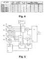
- Fig. 6shows a basic antenna selection scheme for a 4-antenna transmission system comprising a base station 10, e.g. as shown in Fig. 5, where the best two antennas are selected for each of three mobile stations 20-1 to 20-3 based on respective channel selection feedback signals transmitted from the mobile stations 20-1 to 20-3 to the base station 10.
- a first mobile station 20-1has selected antennas A1 and A4 (i.e. channels CH1 and CH4) which are then controlled based on the open-loop (i.e. ST coding) and/or closed-loop (i.e. respective feedback weights) control.
- a second base station 20-2has selected antennas A2 and A4 (i.e.
- a third mobile station 20-3has selected antennas A1 and A3 (i.e. channels CH1 and CH3) for transmission control.
- A1 and A3i.e. channels CH1 and CH3 for transmission control.
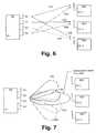
- Fig. 7shows an alternative basic beamforming scheme for a 4-antenna transmission system comprising a base station 10, where the antenna array consisting of the four antennas A1 to A4 is arranged to generate four fixed beams (i.e. channels CH1 to CH4) which can be selected e.g. by the two selectors S1 and S2 shown in Fig. 5.
- an additional controllable phase shifting network(not shown) is required between the transceivers 111 to 114 and the antennas A1 to A4.
- the phase shifting networkis arranged to divide each of the output signals of the transceivers 111 to 114 into four antenna signals and to apply individual phase shifts (or delays) to the antenna signals before supplying them to the antennas A1 to A4.
- the amounts of phase shiftsare controlled so as generate four predetermined fixed beams (i.e. channels CH1 to CH4), wherein each of the fixed beams corresponds to one of the output signals of the transceivers 111 to 114.
- the ST-coded DL signalcan be supplied to two individual ones of the transceivers 111 to 114 and thus to two individual fixed beams.
- the two selected fixed beamsmay then be controlled by the feedback weights so as to optimize the shape of the generated total beam formed by the two selected fixed beams.
- the second mobile station 20-1has selected the fixed beams of the channels CH2 and CH3 which are then controlled based on respective feedback weights so as to generate a resultant optimized beam in order to maximize the transmission gain.
- the selectors S1 and S2are controlled so as to supply the ST-coded parallel signals via the transceivers 112 and 113 to respective input terminals of the phase shifting network (not shown).
- the same beamforming operationmay be performed for the two other mobile stations 20-1 and 20-3 shown in Fig. 7, such that optimized resultant beams are also generated for the mobile stations 20-1 and 20-3.
- the fixed beams of the channels CH1 to CH4can be arranged so that the fixed beams of the channels CH1 and CH2 are orthogonally polarized with respect to the fixed beams of the channels CH3 and CH4.
- Fig. 8shows a diagram indicating simulation results confirming the gains achievable by the selection feedback according to the present invention.
- the diagramshows a raw BER (Bit Error Rate) performance for a mobile station at a speed of 50 km/h.
- M2, 3, 4, 5, and 6.
- an antenna arraycomprising a maximum number of 5 antennas should be selected depending on the desired degree of complexity.
- the present inventionis not limited to the above preferred embodiments but can be applied to any multi-antenna transmitter in order to provide an increased system capacity or spectral efficiency.
- the feedback signalingcan be performed according to any signaling or quantization concept suitable for obtaining transmit weights and the channel selection feedback information at the base station 10.
- the present inventionmay be applied to any wireless communication system comprising a transmit diversity or transmit beamforming concept used between a transmitting element and at least one receiver. Therefore, the above description of the preferred embodiment and the accompanying drawings are only intended to illustrate the present invention. The preferred embodiment of the invention may be varied within the scope of the attached claims.
Landscapes
- Engineering & Computer Science (AREA)
- Computer Networks & Wireless Communication (AREA)
- Signal Processing (AREA)
- Radio Transmission System (AREA)
- Mobile Radio Communication Systems (AREA)
- Radar Systems Or Details Thereof (AREA)
Abstract
Description


Claims (55)
- A method for transmitting a transmission signal froman antenna array(19; A1 to A4) to a receiving means(20)of a wireless communication system, said method comprisingthe steps of:wherein said selection comprises a pre-selectionperformed at said receiving means(20) and a subsequentfinal selection at the transmitting end, anda) performing a signal quality measurement at saidreceiving means(20) for predetermined antennas or beams ofsaid antenna array(19);b) selecting at least two of said predeterminedantennas or beams of said antenna array(19; A1 to A4)based on a feedback information derived from said signalquality measurement; andc) using said at least two selected antennas orbeams for transmitting said transmission signal accordingto a transmit diversity or beamforming scheme,
wherein said final selection is based on said feedbackinformation, an amplifier load condition of channelsassociated with said at least two selected antennas, and adegree of interference to co-channel users of saidassociated channels. - A method according to claim 1, wherein said at leasttwo selected antennas or beams are controlled at least in part based on another feedback information received fromsaid receiving means(20).
- A method according to claim 2, wherein said otherfeedback information is generated based on a channelestimation using respective pilot signals transmitted viasaid at least two selected antennas or beams.
- A method according to claim 3, wherein said respectivepilot signals are transmitted via the CPICH of a WCDMAsystem.
- A method according to any one of the preceding claims,wherein said signal quality measurement is performed bymeasuring a signal strength, SNR or SIR using respectivepilot signals transmitted via each of said predeterminedantenna elements or beams.
- A method according to claim 5, wherein said respectivepilot signals are-transmitted via a secondary pilotchannel.
- A method according to claim 6, wherein said secondarypilot channel is an S-CPICH of a WCDMA system.
- A method according to any one of the preceding claims,wherein said signal quality measurement is repeatedlyperformed for said predetermined number of antennas orbeams after a predetermined time period so as to achieve anadaptive selection.
- A method according to any one of the preceding claims,wherein said transmission signal is transmitted via said atleast two selected antennas or beams by using a space-timecoding scheme.
- A method according to any one of the preceding claims,wherein said predetermined number of antennas or beams isfour.
- A method according to any one of the preceding claims,wherein said feedback information is transmitted using aWCDMA feedback channel.
- A method according to claim 11, wherein said at leasttwo selected antennas or beams have the least attenuationin their associated radio channels.
- A method according to any one of the preceding claims,wherein said feedback information consists of at least onebit.
- A method according to any one of the preceding claims,wherein said selection is performed at said receiving means(20), and said feedback information indicates said at leasttwo selected antennas or beams.
- A method according to any one of the preceding claims,wherein said final selection is based on a statisticalinformation indicating a degree of involvement of aselected antenna in previous selections.
- A method according to any one of thepreceding claims, wherein said selection is performed byusing an evaluation or cost function based on a scoringsystem.
- A method according to any one of the preceding claims,wherein an antenna or beam is selected in said selectionstep when a channel response of a channel associated withsaid antenna or beam exceeds a predetermined threshold.
- A method according to any one of claim 2 to 19,wherein said other feedback information is transmittedusing a feedback signaling of said transmit diversityscheme.
- A method according to claim 18, wherein said feedbackinformation is transmitted using at least one feedback bitof said feedback signaling.
- A method according to claims 18 or 19, wherein saidtransmit diversity scheme is a WCDMA transmit diversityscheme.
- A method according to claim 20, wherein said WCDMAtransmit diversity scheme is an STTD or TxAA scheme or acombination of these.
- A method according to any one of claims 18 to 21,wherein said feedback signaling is performed using FBI bitsof an FSM signal of a WCDMA system.
- A method according to any one of claims 18 to 22,wherein an SSDT signaling is used for said feedbacksignaling.
- A method according to claim 23, wherein an ID of saidSSDT signaling refers to said at least two selectedantennas or beams.
- A method according to claim 1, wherein fixed antennaor beam pairs are selected in said selection step.
- A method according to any one of the preceding claims,wherein said other feedback information comprises feedbackweights used to control the amplitude and/or phase of saidtransmission signal.
- A method according to claim 1, wherein a variablenumber of antennas or beams are selected in said selectionstep.
- A system for transmitting a transmission signal froman antenna array(19; A1 to A4) to a receiving means(20)of a wireless communication system, said system comprising:wherein said selection means(12, 16, 26) comprisespre-selection means(26) arranged at said receiving means(20) and final selection means(12, 16) arranged at thetransmitting end(10), anda) measuring means(26) for performing a signalquality measurement at said receiving means(20) forpredetermined antennas or beams of said antenna array(19;A1 to A4);b) selection means(12, 16, 26) for selecting atleast two of said predetermined antennas or beams of saidantenna array(19; A1 to A4) based on a feedbackinformation derived from said signal quality measurement;andc) transmitting means(19) for transmittingsaid transmission signal using said at least two selectedantennas or beams according to a transmit diversity orbeamforming scheme,
wherein said final selection means(12, 16) arearranged to perform selection based on said feedbackinformation, an amplifier load condition of channelsassociated with said at least two selected antennas, and adegree of interference to co-channel users of saidassociated channels. - A system according to claim 28, further comprisingcontrol means(13, 17) for controlling said at least twoselected antennas or beams at least in part based onanother feedback information received from said receivingmeans (20).
- A system according to claim 28 or 29, furthercomprising pilot control means(18) for generating pilotsignals transmitted via said predetermined antennas orbeams of said antenna array(19; A1 to A4).
- A system according to any one of claims 28 to 30further comprising feedback extraction means(15) forfiltering said feedback information and for supplying thefiltered feedback information to said selection means(12,16).
- A system according to any one of claims 28 to 31,wherein said feedback extraction means(15) is arranged tofilter said other feedback information and to supply thefiltered other feedback information to a weightdetermination means(17) of said control means(13, 17).
- A system according to claim 30, wherein said pilotcontrol means(18) are arranged to perform control suchthat said pilot signals are transmitted via a CPICHchannel.
- A system according to any one of claims 30 to 33,wherein said measuring means(26) are arranged to measure asignal strength, SNR, or SIR by using respective pilotsignals transmitted via each of said predetermined antennaelements or beams.
- A system according to claim 34, wherein said pilotcontrol means(18) are arranged to perform control suchthat said respective pilot signals are transmitted via asecondary pilot channel.
- A system according to claim 35, wherein said secondarypilot channel is an S-CPICH of a WCDMA system.
- A system according to any one of claims 28 to 36,wherein said measuring means(26) are arranged to performsaid signal quality measurement repeatedly for saidpredetermined number of antennas or beams after apredetermined time period.
- A system according to any one of claims 28 to 37,further comprising coding means(14) for coding saidtransmission signal by using a space-time coding scheme,wherein said transmitting means(11) are arranged totransmit the space-time coded transmission signal via saidat least two selected antennas or beams.
- A system according to any one of claims 28 to 38,wherein said selection means(26) are arranged at saidreceiving means(20), and wherein said feedback informationindicates said at least two selected antennas or beams.
- A system according to claim 39, wherein said selectingmeans(36) are arranged to select at least two antennas orbeams having the least attenuation in their associatedradio channels.
- A system according to any one of claims 28 to 40,wherein said final selection means(12, 16) are arranged toperform selection based on a statistical informationindicating a degree of involvement of a selected antenna inprevious selections.
- A system according to any one of claims 28 to 41,wherein said final selection means(12, 16) are arranged toperform selection by using an evaluation or cost functionbased on a scoring system.
- A system according to any one of claims 28 to 42,wherein an antenna or beam is selected by said selectionmeans(12, 26, 26) when a channel response of a channelassociated to said antenna or beam exceeds a predeterminedthreshold.
- A system according to any one of claims 28 to 43,wherein said receiving means(20) comprises feedbackgenerating means(23, 24, 27) for generating said otherfeedback information based on a channel estimationperformed using respective pilot signals transmitted viasaid at least two selected antennas or beams.
- A system according to claim 44, wherein said feedbackgenerating means(23, 24, 27) are arranged to transmit saidother feedback information by using a feedback signaling ofsaid transmit diversity scheme.
- A system according to claim 45, wherein said feedbackgenerating means(23, 24, 27) are arranged to transmit saidfeedback information by using at least one feedback bit ofsaid feedback signaling.
- A system according to claim 45 or 46, wherein saidtransmit diversity scheme is an STTD or TxAA scheme or acombination of these.
- A system according to claim 45 or 46, wherein saidsaid feedback generating means(23, 24, 27) are arranged totransmit said feedback information by using a WCDMAfeedback channel.
- A system according to claim 48, wherein said feedbacksignaling is performed using FBI bits of an FSM signal.
- A system according to claim 44, wherein said feedbackgenerating means(23, 24, 27) are arranged to use an ID ofan SSDT signaling to refer to said at least two selectedantennas or beams.
- A system according to claim 28, wherein said selectionmeans(12, 16, 26) are arranged to select fixed antenna orbeam pairs.
- A system according to any one of claims 28 to 51,wherein said control means(13) are arranged to control theamplitude and/or phase of said transmission signal.
- A method according to claim 28, wherein said selectionmeans(12, 16, 26) are arranged to select a variable numberof antennas or beams.
- A system according to any one of claims 28 to 53,wherein said receiving means is a mobile station (20) andsaid antenna array(19) is arranged at a base station(10)of a WCDMA system.
- A base station for transmitting a transmission signal froman antenna array(19; A1 to A4) to a receiving means(20) of awireless communication system, said base station comprising:wherein said selection means(12, 16) comprises finalselection means(12, 16) being arranged to perform selectionbased on said feedback information, an amplifier loadcondition of channels associated with said at least twoselected antennas, and a degree of interference to co-channelusers of said associated channels.transmitting means (19) for transmitting said transmissionsignal using at least two selected antennas or beams accordingto a transmit diversity or beamforming scheme, andselection means(12, 16) for selecting said at least twoantennas or beams of said antenna array(19; A1 to A4) basedon a feedback information received from said receiving means;
Applications Claiming Priority (1)
| Application Number | Priority Date | Filing Date | Title |
|---|---|---|---|
| PCT/EP2000/003137WO2001078254A1 (en) | 2000-04-07 | 2000-04-07 | Multi-antenna transmission method and system |
Publications (2)
| Publication Number | Publication Date |
|---|---|
| EP1273108A1 EP1273108A1 (en) | 2003-01-08 |
| EP1273108B1true EP1273108B1 (en) | 2005-08-03 |
Family
ID=8163909
Family Applications (1)
| Application Number | Title | Priority Date | Filing Date |
|---|---|---|---|
| EP00917061AExpired - LifetimeEP1273108B1 (en) | 2000-04-07 | 2000-04-07 | Multi-antenna transmission method and system |
Country Status (6)
| Country | Link |
|---|---|
| US (1) | US7403748B1 (en) |
| EP (1) | EP1273108B1 (en) |
| AT (1) | ATE301350T1 (en) |
| AU (1) | AU2000238190A1 (en) |
| DE (1) | DE60021772T2 (en) |
| WO (1) | WO2001078254A1 (en) |
Families Citing this family (132)
| Publication number | Priority date | Publication date | Assignee | Title |
|---|---|---|---|---|
| AU4144799A (en) | 1999-05-19 | 2000-12-12 | Nokia Networks Oy | Transmit diversity method and system |
| US7139324B1 (en)* | 2000-06-02 | 2006-11-21 | Nokia Networks Oy | Closed loop feedback system for improved down link performance |
| US7295509B2 (en) | 2000-09-13 | 2007-11-13 | Qualcomm, Incorporated | Signaling method in an OFDM multiple access system |
| US9130810B2 (en) | 2000-09-13 | 2015-09-08 | Qualcomm Incorporated | OFDM communications methods and apparatus |
| GB2384652B (en) | 2002-01-29 | 2005-11-23 | Hutchison Whampoa Three G Ip | Improved communications with mobile terminals in restricted areas |
| FR2835984B1 (en)* | 2002-02-11 | 2006-06-23 | Evolium Sas | METHOD FOR IMPROVING THE PERFORMANCE OF A MOBILE RADIOCOMMUNICATION SYSTEM |
| CN100481988C (en)* | 2002-05-13 | 2009-04-22 | 美商内数位科技公司 | Allocating resources to users in a slotted CDMA system using beams |
| FI20021094A0 (en)* | 2002-06-07 | 2002-06-07 | Nokia Corp | Ensuring connection in the radio system |
| US7010055B2 (en)* | 2002-06-27 | 2006-03-07 | Motorola, Inc. | System implementing closed loop transmit diversity and method thereof |
| EP1379020A1 (en)* | 2002-07-03 | 2004-01-07 | National University Of Singapore | A wireless communication apparatus and method |
| US8194770B2 (en) | 2002-08-27 | 2012-06-05 | Qualcomm Incorporated | Coded MIMO systems with selective channel inversion applied per eigenmode |
| US8134976B2 (en) | 2002-10-25 | 2012-03-13 | Qualcomm Incorporated | Channel calibration for a time division duplexed communication system |
| US8169944B2 (en) | 2002-10-25 | 2012-05-01 | Qualcomm Incorporated | Random access for wireless multiple-access communication systems |
| US8208364B2 (en) | 2002-10-25 | 2012-06-26 | Qualcomm Incorporated | MIMO system with multiple spatial multiplexing modes |
| US8320301B2 (en) | 2002-10-25 | 2012-11-27 | Qualcomm Incorporated | MIMO WLAN system |
| US20040081131A1 (en) | 2002-10-25 | 2004-04-29 | Walton Jay Rod | OFDM communication system with multiple OFDM symbol sizes |
| US8218609B2 (en) | 2002-10-25 | 2012-07-10 | Qualcomm Incorporated | Closed-loop rate control for a multi-channel communication system |
| US8570988B2 (en) | 2002-10-25 | 2013-10-29 | Qualcomm Incorporated | Channel calibration for a time division duplexed communication system |
| US8170513B2 (en) | 2002-10-25 | 2012-05-01 | Qualcomm Incorporated | Data detection and demodulation for wireless communication systems |
| US7002900B2 (en) | 2002-10-25 | 2006-02-21 | Qualcomm Incorporated | Transmit diversity processing for a multi-antenna communication system |
| US7986742B2 (en) | 2002-10-25 | 2011-07-26 | Qualcomm Incorporated | Pilots for MIMO communication system |
| US7324429B2 (en) | 2002-10-25 | 2008-01-29 | Qualcomm, Incorporated | Multi-mode terminal in a wireless MIMO system |
| US7069052B2 (en) | 2002-11-04 | 2006-06-27 | Nokia Corporation | Data transmission method in base station of radio system, base station of radio system, and antenna array of base station |
| DE10251479A1 (en)* | 2002-11-05 | 2004-05-19 | Siemens Ag | Assessing data transmission channel quality between base station and mobile station, employs two or more antenna elements when assessing information exchange |
| JP3929388B2 (en)* | 2002-11-11 | 2007-06-13 | 松下電器産業株式会社 | Base station apparatus and communication terminal apparatus |
| WO2004049596A1 (en) | 2002-11-26 | 2004-06-10 | Matsushita Electric Industrial Co., Ltd. | Communication method, transmitter apparatus and receiver apparatus |
| US7151951B2 (en)* | 2002-12-23 | 2006-12-19 | Telefonktiebolaget Lm Ericsson (Publ) | Using beamforming and closed loop transmit diversity in a multi-beam antenna system |
| WO2004066104A2 (en)* | 2003-01-23 | 2004-08-05 | Flarion Technologies, Inc. | Methods of providing transmit traversity in wireless |
| JP2005057497A (en)* | 2003-08-04 | 2005-03-03 | Science Univ Of Tokyo | Wireless transmission control method, wireless receiver, and wireless transmitter |
| US7120395B2 (en) | 2003-10-20 | 2006-10-10 | Nortel Networks Limited | MIMO communications |
| JP2005151369A (en)* | 2003-11-19 | 2005-06-09 | Nec Corp | Antenna selection system and method, and radio communication apparatus using the same |
| US9473269B2 (en) | 2003-12-01 | 2016-10-18 | Qualcomm Incorporated | Method and apparatus for providing an efficient control channel structure in a wireless communication system |
| SE0400370D0 (en) | 2004-02-13 | 2004-02-13 | Ericsson Telefon Ab L M | Adaptive MIMO architecture |
| KR100651447B1 (en)* | 2004-04-14 | 2006-11-29 | 삼성전자주식회사 | Antenna reselection system and method in cellular mobile communication system using multiple antennas |
| US9148256B2 (en) | 2004-07-21 | 2015-09-29 | Qualcomm Incorporated | Performance based rank prediction for MIMO design |
| US9137822B2 (en) | 2004-07-21 | 2015-09-15 | Qualcomm Incorporated | Efficient signaling over access channel |
| US9002299B2 (en)* | 2004-10-01 | 2015-04-07 | Cisco Technology, Inc. | Multiple antenna processing on transmit for wireless local area networks |
| KR100909539B1 (en)* | 2004-11-09 | 2009-07-27 | 삼성전자주식회사 | Apparatus and method for supporting various multi-antenna technologies in a broadband wireless access system using multiple antennas |
| US8179834B2 (en)* | 2004-11-19 | 2012-05-15 | Samsung Electronics Co., Ltd. | Method and apparatus for adapting downlink wireless transmission between beamforming and transmit diversity on a per mobile station basis |
| KR100583240B1 (en)* | 2004-11-26 | 2006-05-25 | 한국전자통신연구원 | Optimal Beam Selection Method for Improving Digital Broadcast Reception Performance and Digital Broadcast Receiver Using the Same |
| US20060268623A1 (en)* | 2005-03-09 | 2006-11-30 | Samsung Electronics Co., Ltd. | Transmitting/receiving apparatus and method in a closed-loop MIMO system |
| US9246560B2 (en) | 2005-03-10 | 2016-01-26 | Qualcomm Incorporated | Systems and methods for beamforming and rate control in a multi-input multi-output communication systems |
| US9154211B2 (en) | 2005-03-11 | 2015-10-06 | Qualcomm Incorporated | Systems and methods for beamforming feedback in multi antenna communication systems |
| US8446892B2 (en) | 2005-03-16 | 2013-05-21 | Qualcomm Incorporated | Channel structures for a quasi-orthogonal multiple-access communication system |
| US9520972B2 (en) | 2005-03-17 | 2016-12-13 | Qualcomm Incorporated | Pilot signal transmission for an orthogonal frequency division wireless communication system |
| US9143305B2 (en) | 2005-03-17 | 2015-09-22 | Qualcomm Incorporated | Pilot signal transmission for an orthogonal frequency division wireless communication system |
| US9461859B2 (en) | 2005-03-17 | 2016-10-04 | Qualcomm Incorporated | Pilot signal transmission for an orthogonal frequency division wireless communication system |
| US9184870B2 (en) | 2005-04-01 | 2015-11-10 | Qualcomm Incorporated | Systems and methods for control channel signaling |
| US7957351B2 (en)* | 2005-04-04 | 2011-06-07 | Qualcomm Incorporated | Method and apparatus for management of multi-carrier communications in a wireless communication system |
| US9408220B2 (en) | 2005-04-19 | 2016-08-02 | Qualcomm Incorporated | Channel quality reporting for adaptive sectorization |
| US9036538B2 (en) | 2005-04-19 | 2015-05-19 | Qualcomm Incorporated | Frequency hopping design for single carrier FDMA systems |
| US7466749B2 (en) | 2005-05-12 | 2008-12-16 | Qualcomm Incorporated | Rate selection with margin sharing |
| CN1870461B (en) | 2005-05-24 | 2011-06-01 | 都科摩(北京)通信技术研究中心有限公司 | Random Transmit Beamforming Based MIMO System and Its User Scheduling Method |
| US8565194B2 (en) | 2005-10-27 | 2013-10-22 | Qualcomm Incorporated | Puncturing signaling channel for a wireless communication system |
| US8879511B2 (en) | 2005-10-27 | 2014-11-04 | Qualcomm Incorporated | Assignment acknowledgement for a wireless communication system |
| US8611284B2 (en) | 2005-05-31 | 2013-12-17 | Qualcomm Incorporated | Use of supplemental assignments to decrement resources |
| US8462859B2 (en) | 2005-06-01 | 2013-06-11 | Qualcomm Incorporated | Sphere decoding apparatus |
| US8358714B2 (en) | 2005-06-16 | 2013-01-22 | Qualcomm Incorporated | Coding and modulation for multiple data streams in a communication system |
| US8599945B2 (en)* | 2005-06-16 | 2013-12-03 | Qualcomm Incorporated | Robust rank prediction for a MIMO system |
| US9179319B2 (en) | 2005-06-16 | 2015-11-03 | Qualcomm Incorporated | Adaptive sectorization in cellular systems |
| US8885628B2 (en) | 2005-08-08 | 2014-11-11 | Qualcomm Incorporated | Code division multiplexing in a single-carrier frequency division multiple access system |
| KR100629490B1 (en)* | 2005-08-18 | 2006-09-28 | 삼성전자주식회사 | Transmission apparatus and method of transmission diversity system |
| US20070041457A1 (en) | 2005-08-22 | 2007-02-22 | Tamer Kadous | Method and apparatus for providing antenna diversity in a wireless communication system |
| US9209956B2 (en) | 2005-08-22 | 2015-12-08 | Qualcomm Incorporated | Segment sensitive scheduling |
| US8644292B2 (en) | 2005-08-24 | 2014-02-04 | Qualcomm Incorporated | Varied transmission time intervals for wireless communication system |
| US9136974B2 (en) | 2005-08-30 | 2015-09-15 | Qualcomm Incorporated | Precoding and SDMA support |
| US7917100B2 (en) | 2005-09-21 | 2011-03-29 | Broadcom Corporation | Method and system for a double search user group selection scheme with range in TDD multiuser MIMO downlink transmission |
| US7917101B2 (en)* | 2005-09-21 | 2011-03-29 | Broadcom Corporation | Method and system for a greedy user group selection with range reduction in TDD multiuser MIMO downlink transmission |
| US7515878B2 (en)* | 2005-09-21 | 2009-04-07 | Broadcom Corporation | Method and system for greedy user group selection with range reduction for FDD multiuser MIMO downlink transmission with finite-rate channel state information feedback |
| US7630337B2 (en)* | 2005-09-21 | 2009-12-08 | Broadcom Corporation | Method and system for an improved user group selection scheme with finite-rate channel state information feedback for FDD multiuser MIMO downlink transmission |
| US8068872B2 (en)* | 2005-10-06 | 2011-11-29 | Telefonaktiebolaget Lm Ericsson (Publ) | Signaling support for antenna selection using subset lists and subset masks |
| KR101241881B1 (en)* | 2005-10-26 | 2013-03-11 | 엘지전자 주식회사 | Method for encoding space-time codes in multi-antenna system |
| US9172453B2 (en) | 2005-10-27 | 2015-10-27 | Qualcomm Incorporated | Method and apparatus for pre-coding frequency division duplexing system |
| US8693405B2 (en) | 2005-10-27 | 2014-04-08 | Qualcomm Incorporated | SDMA resource management |
| US9088384B2 (en) | 2005-10-27 | 2015-07-21 | Qualcomm Incorporated | Pilot symbol transmission in wireless communication systems |
| US9210651B2 (en) | 2005-10-27 | 2015-12-08 | Qualcomm Incorporated | Method and apparatus for bootstraping information in a communication system |
| WO2007048427A1 (en)* | 2005-10-27 | 2007-05-03 | Telecom Italia S.P.A. | Method and system for multiple antenna communications using multiple transmission modes, related apparatus and computer program product |
| US8582509B2 (en) | 2005-10-27 | 2013-11-12 | Qualcomm Incorporated | Scalable frequency band operation in wireless communication systems |
| US9225488B2 (en) | 2005-10-27 | 2015-12-29 | Qualcomm Incorporated | Shared signaling channel |
| US9225416B2 (en) | 2005-10-27 | 2015-12-29 | Qualcomm Incorporated | Varied signaling channels for a reverse link in a wireless communication system |
| US8477684B2 (en) | 2005-10-27 | 2013-07-02 | Qualcomm Incorporated | Acknowledgement of control messages in a wireless communication system |
| US8045512B2 (en) | 2005-10-27 | 2011-10-25 | Qualcomm Incorporated | Scalable frequency band operation in wireless communication systems |
| US9144060B2 (en) | 2005-10-27 | 2015-09-22 | Qualcomm Incorporated | Resource allocation for shared signaling channels |
| US8582548B2 (en) | 2005-11-18 | 2013-11-12 | Qualcomm Incorporated | Frequency division multiple access schemes for wireless communication |
| US8831607B2 (en) | 2006-01-05 | 2014-09-09 | Qualcomm Incorporated | Reverse link other sector communication |
| EP1843485B1 (en) | 2006-03-30 | 2016-06-08 | Sony Deutschland Gmbh | Multiple-input multiple-output (MIMO) spatial multiplexing system with dynamic antenna beam combination selection capability |
| WO2008021644A2 (en)* | 2006-08-15 | 2008-02-21 | Cisco Technology, Inc. | Method for antenna array partitioning |
| DE602006014398D1 (en)* | 2006-08-21 | 2010-07-01 | Sony Deutschland Gmbh | Apparatus and method for selecting antennas in a radio communication system |
| US8335202B2 (en) | 2006-11-20 | 2012-12-18 | Qualcomm Incorporated | Sending pilots on secondary channels for improved acquisition and handoff in cellular communication |
| ATE496434T1 (en)* | 2006-11-29 | 2011-02-15 | Telecom Italia Spa | SWITCHING BEAM ANTENNA SYSTEM AND METHOD USING DIGITALLY CONTROLLED WEIGHTED HIGH FREQUENCY COMBINATION |
| JP5022017B2 (en)* | 2006-12-15 | 2012-09-12 | 株式会社日立製作所 | OFDM cellular wireless communication method, system and base station |
| US8750811B2 (en)* | 2007-03-14 | 2014-06-10 | Google Inc. | Method, apparatus and system for phase difference adjustment in transmit diversity |
| US7720086B2 (en)* | 2007-03-19 | 2010-05-18 | Microsoft Corporation | Distributed overlay multi-channel media access control for wireless ad hoc networks |
| US7801238B2 (en)* | 2007-03-30 | 2010-09-21 | Alcatel-Lucent Usa Inc. | MIMO communication system with user scheduling based on reduced channel state information |
| KR101346042B1 (en) | 2007-07-31 | 2013-12-31 | 재단법인서울대학교산학협력재단 | Method of communicating multi input multi output and system using the same |
| US7907677B2 (en)* | 2007-08-10 | 2011-03-15 | Intel Corporation | Open loop MU-MIMO |
| WO2009080057A1 (en)* | 2007-12-19 | 2009-07-02 | Telecom Italia S.P.A. | Method and system for switched beam antenna communications |
| US8085721B2 (en)* | 2008-03-10 | 2011-12-27 | Elektrobit Wireless Communications Oy | Adaptive transmission method and a base station using the method |
| US9100068B2 (en)* | 2008-03-17 | 2015-08-04 | Qualcomm, Incorporated | Multi-resolution beamforming in MIMO systems |
| WO2010043752A1 (en)* | 2008-10-16 | 2010-04-22 | Elektrobit Wireless Communications Oy | Beam forming method, apparatus and system |
| WO2010058245A1 (en)* | 2008-11-20 | 2010-05-27 | Nokia Corporation | Pre-coding for downlink control channel |
| JP5186355B2 (en)* | 2008-12-25 | 2013-04-17 | 株式会社Kddi研究所 | Communication characteristic measuring apparatus and wireless terminal |
| EP2392048B1 (en) | 2009-02-02 | 2018-10-31 | Commonwealth Scientific and Industrial Research Organisation | Hybrid adaptive antenna array |
| US8437361B2 (en)* | 2009-03-17 | 2013-05-07 | Cisco Technology, Inc. | Adaptive subchannel disabling in beamformed wireless communication systems |
| WO2010138735A1 (en) | 2009-05-27 | 2010-12-02 | At&T Intellectual Property I, L.P. | Transmit antenna subset selection for retransmission |
| US9136932B2 (en)* | 2009-11-09 | 2015-09-15 | Telefonaktiebolaget L M Ecrisson (publ) | Method and arrangement for tuning polarizations for orthogonally polarized antennas |
| US8559990B2 (en)* | 2010-02-05 | 2013-10-15 | Qualcomm Incorporated | Apparatus and method for enabling uplink beamforming transit diversity channel estimation |
| PT2580811T (en)* | 2010-06-11 | 2018-06-12 | Ericsson Telefon Ab L M | A node in a communication system with switchable antenna functions |
| US8937900B2 (en) | 2010-07-20 | 2015-01-20 | Qualcomm Incorporated | Enhancing pilot channel transmission in TD-SCDMA multicarrier systems using secondary carrier frequencies |
| KR20120032777A (en)* | 2010-09-29 | 2012-04-06 | 삼성전자주식회사 | Method and apparatus for determining downlink beamforming vectors in hierarchical cell communication system |
| JP5432882B2 (en)* | 2010-11-25 | 2014-03-05 | 株式会社日立製作所 | Distributed antenna system, distributed antenna switching method, base station apparatus, and antenna switch apparatus |
| GB2495110B (en)* | 2011-09-28 | 2014-03-19 | Toshiba Res Europ Ltd | Antenna combining |
| US8843150B2 (en) | 2011-12-28 | 2014-09-23 | Samsung Electronics Co., Ltd. | Beamforming method and apparatus for acquiring transmission beam diversity in a wireless communication system |
| KR20140006304A (en)* | 2012-07-03 | 2014-01-16 | 한국전자통신연구원 | Method for receiving downlink data and machine type communication device using the method |
| US9674718B2 (en)* | 2012-08-09 | 2017-06-06 | Telefonaktiebolaget Lm Ericsson (Publ) | Microwave link control |
| JP2015528653A (en)* | 2012-08-22 | 2015-09-28 | ノキア ソリューションズ アンド ネットワークス オサケユキチュア | Determining transmission parameters |
| CN107251618B (en)* | 2015-01-16 | 2021-05-14 | 梁平 | Beamforming in a multi-user multiple-input multiple-output wireless communication system with repeaters |
| EP3314963B1 (en) | 2015-06-25 | 2019-04-24 | Airspan Networks Inc. | Managing external interference in a wireless network |
| GB2539722B (en) | 2015-06-25 | 2021-10-13 | Airspan Ip Holdco Llc | Bearing calculation |
| GB2539732A (en)* | 2015-06-25 | 2016-12-28 | Airspan Networks Inc | A configurable antenna and method of operating such a configurable antenna |
| GB2539727B (en) | 2015-06-25 | 2021-05-12 | Airspan Ip Holdco Llc | A configurable antenna and method of operating such a configurable antenna |
| GB2539736A (en) | 2015-06-25 | 2016-12-28 | Airspan Networks Inc | Wireless network configuration using path loss determination between nodes |
| GB2539735A (en) | 2015-06-25 | 2016-12-28 | Airspan Networks Inc | Sub-sampling antenna elements |
| GB2539730B (en) | 2015-06-25 | 2021-04-07 | Airspan Ip Holdco Llc | Node role assignment in networks |
| GB2539731B (en) | 2015-06-25 | 2021-08-04 | Airspan Ip Holdco Llc | Quality of service in wireless backhauls |
| GB2545697B (en) | 2015-12-22 | 2020-01-08 | Airties Kablosuz Iletism Sanayi Ve Disticaret As | Dynamic channel selection and DFS re-entry |
| US10177445B1 (en)* | 2017-07-05 | 2019-01-08 | National Chung Shan Institute Of Science And Technology | Communication structure |
| KR102456783B1 (en)* | 2018-04-16 | 2022-10-21 | 삼성전자 주식회사 | Electronic apparatus and the control method thereof |
| CN110896550A (en) | 2018-09-12 | 2020-03-20 | 索尼公司 | Electronic device and method for wireless communication, computer-readable storage medium |
| US10638475B2 (en) | 2018-09-12 | 2020-04-28 | Verizon Patent And Licensing Inc. | Systems and methods for dynamically adjusting subframes |
| US12041589B2 (en) | 2020-08-17 | 2024-07-16 | Charter Communications Operating, Llc | Methods and apparatus for spectrum utilization coordination between wireline backhaul and wireless systems |
| US11563593B2 (en) | 2020-08-19 | 2023-01-24 | Charter Communications Operating, Llc | Methods and apparatus for coordination between wireline backhaul and wireless systems |
Family Cites Families (8)
| Publication number | Priority date | Publication date | Assignee | Title |
|---|---|---|---|---|
| EP0755127B1 (en)* | 1995-07-19 | 2003-08-27 | Nec Corporation | CDMA diversity transmission system |
| EP0966125B1 (en)* | 1998-06-15 | 2007-04-04 | Motorola, Inc. | Method and apparatus for improving capacity in a radio communications system |
| US6067324A (en) | 1998-06-30 | 2000-05-23 | Motorola, Inc. | Method and system for transmitting and demodulating a communications signal using an adaptive antenna array in a wireless communication system |
| FI982763L (en) | 1998-12-21 | 2000-06-22 | Nokia Networks Oy | Communication method and radio system |
| US6775260B1 (en)* | 1999-02-25 | 2004-08-10 | Texas Instruments Incorporated | Space time transmit diversity for TDD/WCDMA systems |
| AU4144799A (en)* | 1999-05-19 | 2000-12-12 | Nokia Networks Oy | Transmit diversity method and system |
| KR100689398B1 (en)* | 1999-10-09 | 2007-03-08 | 삼성전자주식회사 | Apparatus and Method for Closed Loop Transmit Antenna Diversity in Mobile Communication Systems |
| EP1204219B1 (en)* | 2000-10-11 | 2008-04-09 | Samsung Electronics Co., Ltd. | Apparatus and method for controlling transmit antenna array for physical downlink shared channel in a mobile communication system |
- 2000
- 2000-04-07EPEP00917061Apatent/EP1273108B1/ennot_activeExpired - Lifetime
- 2000-04-07WOPCT/EP2000/003137patent/WO2001078254A1/enactiveIP Right Grant
- 2000-04-07USUS10/240,628patent/US7403748B1/ennot_activeExpired - Lifetime
- 2000-04-07ATAT00917061Tpatent/ATE301350T1/ennot_activeIP Right Cessation
- 2000-04-07AUAU2000238190Apatent/AU2000238190A1/ennot_activeAbandoned
- 2000-04-07DEDE60021772Tpatent/DE60021772T2/ennot_activeExpired - Lifetime
Also Published As
| Publication number | Publication date |
|---|---|
| ATE301350T1 (en) | 2005-08-15 |
| WO2001078254A1 (en) | 2001-10-18 |
| DE60021772T2 (en) | 2006-04-20 |
| DE60021772D1 (en) | 2005-09-08 |
| EP1273108A1 (en) | 2003-01-08 |
| US7403748B1 (en) | 2008-07-22 |
| AU2000238190A1 (en) | 2001-10-23 |
Similar Documents
| Publication | Publication Date | Title |
|---|---|---|
| EP1273108B1 (en) | Multi-antenna transmission method and system | |
| EP1266463B1 (en) | Transmit diversity method and system | |
| EP1175022B1 (en) | Transmission antenna diversity method, base station and mobile station therefor | |
| EP1330050B1 (en) | A method and device for downlink feedback multiple antenna transmit in wireless communication system | |
| JP3987727B2 (en) | Beam forming method | |
| KR101513889B1 (en) | Switch beam forming apparatus and method using multi-beam combining | |
| EP1334573B1 (en) | Method for controlling the data signal weighting in multi-element transceivers and corresponding devices and telecommunications network | |
| JP4027224B2 (en) | Beam forming method | |
| KR100790165B1 (en) | Method and system for data transmission in communication system | |
| US7151951B2 (en) | Using beamforming and closed loop transmit diversity in a multi-beam antenna system | |
| JP5223012B2 (en) | System for wireless communication and method for providing wireless communication | |
| KR100575930B1 (en) | Apparatus and Method for Transmitting Diversity in Transmit Diversity in Mobile Communication System Using Transmit Diversity | |
| US20020105961A1 (en) | Transmit diversity method and system | |
| KR101660200B1 (en) | Antenna reconfiguration for mimo communications when multiplicative noise limited | |
| KR20050120441A (en) | Transmission diversity apparatus and method using multiple antenna in a mobile communication system | |
| WO2003055099A1 (en) | Parameter estimation for adaptive antenna system | |
| US20040082299A1 (en) | Method for controlling the formation of a downlink beam |
Legal Events
| Date | Code | Title | Description |
|---|---|---|---|
| PUAI | Public reference made under article 153(3) epc to a published international application that has entered the european phase | Free format text:ORIGINAL CODE: 0009012 | |
| 17P | Request for examination filed | Effective date:20021106 | |
| AK | Designated contracting states | Kind code of ref document:A1 Designated state(s):AT BE CH CY DE DK ES FI FR GB GR IE IT LI LU MC NL PT SE | |
| AX | Request for extension of the european patent | Free format text:AL;LT;LV;MK;RO;SI | |
| RIN1 | Information on inventor provided before grant (corrected) | Inventor name:KATZ, MARCOS Inventor name:KESKITALO, ILKKANOKIA NETWORKS OY Inventor name:YLITALO, JUHA | |
| GRAP | Despatch of communication of intention to grant a patent | Free format text:ORIGINAL CODE: EPIDOSNIGR1 | |
| GRAS | Grant fee paid | Free format text:ORIGINAL CODE: EPIDOSNIGR3 | |
| GRAA | (expected) grant | Free format text:ORIGINAL CODE: 0009210 | |
| 17Q | First examination report despatched | Effective date:20050531 | |
| AK | Designated contracting states | Kind code of ref document:B1 Designated state(s):AT BE CH CY DE DK ES FI FR GB GR IE IT LI LU MC NL PT SE | |
| PG25 | Lapsed in a contracting state [announced via postgrant information from national office to epo] | Ref country code:IT Free format text:LAPSE BECAUSE OF FAILURE TO SUBMIT A TRANSLATION OF THE DESCRIPTION OR TO PAY THE FEE WITHIN THE PRE;WARNING: LAPSES OF ITALIAN PATENTS WITH EFFECTIVE DATE BEFORE 2007 MAY HAVE OCCURRED AT ANY TIME BEFORE 2007. THE CORRECT EFFECTIVE DATE MAY BE DIFFERENT FROM THE ONE RECORDED.SCRIBED TIME-LIMIT Effective date:20050803 Ref country code:FI Free format text:LAPSE BECAUSE OF FAILURE TO SUBMIT A TRANSLATION OF THE DESCRIPTION OR TO PAY THE FEE WITHIN THE PRESCRIBED TIME-LIMIT Effective date:20050803 Ref country code:CH Free format text:LAPSE BECAUSE OF FAILURE TO SUBMIT A TRANSLATION OF THE DESCRIPTION OR TO PAY THE FEE WITHIN THE PRESCRIBED TIME-LIMIT Effective date:20050803 Ref country code:BE Free format text:LAPSE BECAUSE OF FAILURE TO SUBMIT A TRANSLATION OF THE DESCRIPTION OR TO PAY THE FEE WITHIN THE PRESCRIBED TIME-LIMIT Effective date:20050803 Ref country code:NL Free format text:LAPSE BECAUSE OF FAILURE TO SUBMIT A TRANSLATION OF THE DESCRIPTION OR TO PAY THE FEE WITHIN THE PRESCRIBED TIME-LIMIT Effective date:20050803 Ref country code:AT Free format text:LAPSE BECAUSE OF FAILURE TO SUBMIT A TRANSLATION OF THE DESCRIPTION OR TO PAY THE FEE WITHIN THE PRESCRIBED TIME-LIMIT Effective date:20050803 Ref country code:LI Free format text:LAPSE BECAUSE OF FAILURE TO SUBMIT A TRANSLATION OF THE DESCRIPTION OR TO PAY THE FEE WITHIN THE PRESCRIBED TIME-LIMIT Effective date:20050803 | |
| REG | Reference to a national code | Ref country code:GB Ref legal event code:FG4D | |
| REG | Reference to a national code | Ref country code:CH Ref legal event code:EP | |
| REG | Reference to a national code | Ref country code:IE Ref legal event code:FG4D | |
| REF | Corresponds to: | Ref document number:60021772 Country of ref document:DE Date of ref document:20050908 Kind code of ref document:P | |
| PG25 | Lapsed in a contracting state [announced via postgrant information from national office to epo] | Ref country code:DK Free format text:LAPSE BECAUSE OF FAILURE TO SUBMIT A TRANSLATION OF THE DESCRIPTION OR TO PAY THE FEE WITHIN THE PRESCRIBED TIME-LIMIT Effective date:20051103 Ref country code:GR Free format text:LAPSE BECAUSE OF FAILURE TO SUBMIT A TRANSLATION OF THE DESCRIPTION OR TO PAY THE FEE WITHIN THE PRESCRIBED TIME-LIMIT Effective date:20051103 Ref country code:SE Free format text:LAPSE BECAUSE OF FAILURE TO SUBMIT A TRANSLATION OF THE DESCRIPTION OR TO PAY THE FEE WITHIN THE PRESCRIBED TIME-LIMIT Effective date:20051103 | |
| PG25 | Lapsed in a contracting state [announced via postgrant information from national office to epo] | Ref country code:ES Free format text:LAPSE BECAUSE OF FAILURE TO SUBMIT A TRANSLATION OF THE DESCRIPTION OR TO PAY THE FEE WITHIN THE PRESCRIBED TIME-LIMIT Effective date:20051114 | |
| PG25 | Lapsed in a contracting state [announced via postgrant information from national office to epo] | Ref country code:PT Free format text:LAPSE BECAUSE OF FAILURE TO SUBMIT A TRANSLATION OF THE DESCRIPTION OR TO PAY THE FEE WITHIN THE PRESCRIBED TIME-LIMIT Effective date:20060103 | |
| NLV1 | Nl: lapsed or annulled due to failure to fulfill the requirements of art. 29p and 29m of the patents act | ||
| REG | Reference to a national code | Ref country code:CH Ref legal event code:PL | |
| PG25 | Lapsed in a contracting state [announced via postgrant information from national office to epo] | Ref country code:IE Free format text:LAPSE BECAUSE OF NON-PAYMENT OF DUE FEES Effective date:20060407 | |
| PG25 | Lapsed in a contracting state [announced via postgrant information from national office to epo] | Ref country code:MC Free format text:LAPSE BECAUSE OF NON-PAYMENT OF DUE FEES Effective date:20060430 | |
| PLBE | No opposition filed within time limit | Free format text:ORIGINAL CODE: 0009261 | |
| STAA | Information on the status of an ep patent application or granted ep patent | Free format text:STATUS: NO OPPOSITION FILED WITHIN TIME LIMIT | |
| 26N | No opposition filed | Effective date:20060504 | |
| EN | Fr: translation not filed | ||
| PG25 | Lapsed in a contracting state [announced via postgrant information from national office to epo] | Ref country code:FR Free format text:LAPSE BECAUSE OF FAILURE TO SUBMIT A TRANSLATION OF THE DESCRIPTION OR TO PAY THE FEE WITHIN THE PRESCRIBED TIME-LIMIT Effective date:20060929 | |
| REG | Reference to a national code | Ref country code:IE Ref legal event code:MM4A | |
| PG25 | Lapsed in a contracting state [announced via postgrant information from national office to epo] | Ref country code:LU Free format text:LAPSE BECAUSE OF NON-PAYMENT OF DUE FEES Effective date:20060407 | |
| PG25 | Lapsed in a contracting state [announced via postgrant information from national office to epo] | Ref country code:FR Free format text:LAPSE BECAUSE OF FAILURE TO SUBMIT A TRANSLATION OF THE DESCRIPTION OR TO PAY THE FEE WITHIN THE PRESCRIBED TIME-LIMIT Effective date:20050803 Ref country code:CY Free format text:LAPSE BECAUSE OF FAILURE TO SUBMIT A TRANSLATION OF THE DESCRIPTION OR TO PAY THE FEE WITHIN THE PRESCRIBED TIME-LIMIT Effective date:20050803 | |
| PGFP | Annual fee paid to national office [announced via postgrant information from national office to epo] | Ref country code:GB Payment date:20110406 Year of fee payment:12 | |
| GBPC | Gb: european patent ceased through non-payment of renewal fee | Effective date:20120407 | |
| PG25 | Lapsed in a contracting state [announced via postgrant information from national office to epo] | Ref country code:GB Free format text:LAPSE BECAUSE OF NON-PAYMENT OF DUE FEES Effective date:20120407 | |
| REG | Reference to a national code | Ref country code:DE Ref legal event code:R082 Ref document number:60021772 Country of ref document:DE Representative=s name:TBK, DE Ref country code:DE Ref legal event code:R081 Ref document number:60021772 Country of ref document:DE Owner name:NOKIA TECHNOLOGIES OY, FI Free format text:FORMER OWNER: NOKIA CORP., 02610 ESPOO, FI | |
| PGFP | Annual fee paid to national office [announced via postgrant information from national office to epo] | Ref country code:DE Payment date:20160330 Year of fee payment:17 | |
| REG | Reference to a national code | Ref country code:DE Ref legal event code:R119 Ref document number:60021772 Country of ref document:DE | |
| PG25 | Lapsed in a contracting state [announced via postgrant information from national office to epo] | Ref country code:DE Free format text:LAPSE BECAUSE OF NON-PAYMENT OF DUE FEES Effective date:20171103 | |
| REG | Reference to a national code | Ref country code:DE Ref legal event code:R082 Ref document number:60021772 Country of ref document:DE Representative=s name:BARKHOFF REIMANN VOSSIUS, DE Ref country code:DE Ref legal event code:R081 Ref document number:60021772 Country of ref document:DE Owner name:WSOU INVESTMENTS, LLC, LOS ANGELES, US Free format text:FORMER OWNER: NOKIA TECHNOLOGIES OY, ESPOO, FI |