EP1271465B1 - Method for calibrating, characterizing and driving a color flat panel display - Google Patents
Method for calibrating, characterizing and driving a color flat panel displayDownload PDFInfo
- Publication number
- EP1271465B1 EP1271465B1EP02077262.0AEP02077262AEP1271465B1EP 1271465 B1EP1271465 B1EP 1271465B1EP 02077262 AEP02077262 AEP 02077262AEP 1271465 B1EP1271465 B1EP 1271465B1
- Authority
- EP
- European Patent Office
- Prior art keywords
- luminance level
- target
- flat panel
- chromaticities
- panel display
- Prior art date
- Legal status (The legal status is an assumption and is not a legal conclusion. Google has not performed a legal analysis and makes no representation as to the accuracy of the status listed.)
- Expired - Lifetime
Links
- 238000000034methodMethods0.000titleclaimsdescription11
- 230000007935neutral effectEffects0.000description15
- 238000012545processingMethods0.000description10
- 238000009125cardiac resynchronization therapyMethods0.000description8
- 239000011159matrix materialSubstances0.000description8
- 238000001228spectrumMethods0.000description7
- 230000006978adaptationEffects0.000description5
- 238000012512characterization methodMethods0.000description5
- 230000007246mechanismEffects0.000description5
- 230000004044responseEffects0.000description5
- 239000003086colorantSubstances0.000description4
- 238000004519manufacturing processMethods0.000description4
- 230000008901benefitEffects0.000description3
- 238000003384imaging methodMethods0.000description3
- 230000003595spectral effectEffects0.000description3
- 238000013459approachMethods0.000description2
- 238000013507mappingMethods0.000description2
- 230000008569processEffects0.000description2
- 230000001131transforming effectEffects0.000description2
- OAICVXFJPJFONN-UHFFFAOYSA-NPhosphorusChemical compound[P]OAICVXFJPJFONN-UHFFFAOYSA-N0.000description1
- YTAHJIFKAKIKAV-XNMGPUDCSA-N[(1R)-3-morpholin-4-yl-1-phenylpropyl] N-[(3S)-2-oxo-5-phenyl-1,3-dihydro-1,4-benzodiazepin-3-yl]carbamateChemical compoundO=C1[C@H](N=C(C2=C(N1)C=CC=C2)C1=CC=CC=C1)NC(O[C@H](CCN1CCOCC1)C1=CC=CC=C1)=OYTAHJIFKAKIKAV-XNMGPUDCSA-N0.000description1
- 238000012937correctionMethods0.000description1
- 230000001419dependent effectEffects0.000description1
- 238000013461designMethods0.000description1
- 238000011161developmentMethods0.000description1
- 230000018109developmental processEffects0.000description1
- 238000010586diagramMethods0.000description1
- 230000002431foraging effectEffects0.000description1
- 230000006870functionEffects0.000description1
- 230000003287optical effectEffects0.000description1
- 230000000737periodic effectEffects0.000description1
- 238000011160researchMethods0.000description1
- 230000035945sensitivityEffects0.000description1
- 238000012360testing methodMethods0.000description1
- 230000000007visual effectEffects0.000description1
Images


Classifications
- G—PHYSICS
- G09—EDUCATION; CRYPTOGRAPHY; DISPLAY; ADVERTISING; SEALS
- G09G—ARRANGEMENTS OR CIRCUITS FOR CONTROL OF INDICATING DEVICES USING STATIC MEANS TO PRESENT VARIABLE INFORMATION
- G09G3/00—Control arrangements or circuits, of interest only in connection with visual indicators other than cathode-ray tubes
- G09G3/20—Control arrangements or circuits, of interest only in connection with visual indicators other than cathode-ray tubes for presentation of an assembly of a number of characters, e.g. a page, by composing the assembly by combination of individual elements arranged in a matrix no fixed position being assigned to or needed to be assigned to the individual characters or partial characters
- G09G3/2092—Details of a display terminals using a flat panel, the details relating to the control arrangement of the display terminal and to the interfaces thereto
- G—PHYSICS
- G09—EDUCATION; CRYPTOGRAPHY; DISPLAY; ADVERTISING; SEALS
- G09G—ARRANGEMENTS OR CIRCUITS FOR CONTROL OF INDICATING DEVICES USING STATIC MEANS TO PRESENT VARIABLE INFORMATION
- G09G3/00—Control arrangements or circuits, of interest only in connection with visual indicators other than cathode-ray tubes
- G09G3/20—Control arrangements or circuits, of interest only in connection with visual indicators other than cathode-ray tubes for presentation of an assembly of a number of characters, e.g. a page, by composing the assembly by combination of individual elements arranged in a matrix no fixed position being assigned to or needed to be assigned to the individual characters or partial characters
- G09G3/2003—Display of colours
- G—PHYSICS
- G09—EDUCATION; CRYPTOGRAPHY; DISPLAY; ADVERTISING; SEALS
- G09G—ARRANGEMENTS OR CIRCUITS FOR CONTROL OF INDICATING DEVICES USING STATIC MEANS TO PRESENT VARIABLE INFORMATION
- G09G3/00—Control arrangements or circuits, of interest only in connection with visual indicators other than cathode-ray tubes
- G09G3/20—Control arrangements or circuits, of interest only in connection with visual indicators other than cathode-ray tubes for presentation of an assembly of a number of characters, e.g. a page, by composing the assembly by combination of individual elements arranged in a matrix no fixed position being assigned to or needed to be assigned to the individual characters or partial characters
- G09G3/22—Control arrangements or circuits, of interest only in connection with visual indicators other than cathode-ray tubes for presentation of an assembly of a number of characters, e.g. a page, by composing the assembly by combination of individual elements arranged in a matrix no fixed position being assigned to or needed to be assigned to the individual characters or partial characters using controlled light sources
- G09G3/30—Control arrangements or circuits, of interest only in connection with visual indicators other than cathode-ray tubes for presentation of an assembly of a number of characters, e.g. a page, by composing the assembly by combination of individual elements arranged in a matrix no fixed position being assigned to or needed to be assigned to the individual characters or partial characters using controlled light sources using electroluminescent panels
- G09G3/32—Control arrangements or circuits, of interest only in connection with visual indicators other than cathode-ray tubes for presentation of an assembly of a number of characters, e.g. a page, by composing the assembly by combination of individual elements arranged in a matrix no fixed position being assigned to or needed to be assigned to the individual characters or partial characters using controlled light sources using electroluminescent panels semiconductive, e.g. using light-emitting diodes [LED]
- G09G3/3208—Control arrangements or circuits, of interest only in connection with visual indicators other than cathode-ray tubes for presentation of an assembly of a number of characters, e.g. a page, by composing the assembly by combination of individual elements arranged in a matrix no fixed position being assigned to or needed to be assigned to the individual characters or partial characters using controlled light sources using electroluminescent panels semiconductive, e.g. using light-emitting diodes [LED] organic, e.g. using organic light-emitting diodes [OLED]
- H—ELECTRICITY
- H04—ELECTRIC COMMUNICATION TECHNIQUE
- H04N—PICTORIAL COMMUNICATION, e.g. TELEVISION
- H04N17/00—Diagnosis, testing or measuring for television systems or their details
- H04N17/02—Diagnosis, testing or measuring for television systems or their details for colour television signals
- H—ELECTRICITY
- H04—ELECTRIC COMMUNICATION TECHNIQUE
- H04N—PICTORIAL COMMUNICATION, e.g. TELEVISION
- H04N17/00—Diagnosis, testing or measuring for television systems or their details
- H04N17/04—Diagnosis, testing or measuring for television systems or their details for receivers
- G—PHYSICS
- G09—EDUCATION; CRYPTOGRAPHY; DISPLAY; ADVERTISING; SEALS
- G09G—ARRANGEMENTS OR CIRCUITS FOR CONTROL OF INDICATING DEVICES USING STATIC MEANS TO PRESENT VARIABLE INFORMATION
- G09G2320/00—Control of display operating conditions
- G09G2320/02—Improving the quality of display appearance
- G09G2320/029—Improving the quality of display appearance by monitoring one or more pixels in the display panel, e.g. by monitoring a fixed reference pixel
- G—PHYSICS
- G09—EDUCATION; CRYPTOGRAPHY; DISPLAY; ADVERTISING; SEALS
- G09G—ARRANGEMENTS OR CIRCUITS FOR CONTROL OF INDICATING DEVICES USING STATIC MEANS TO PRESENT VARIABLE INFORMATION
- G09G2320/00—Control of display operating conditions
- G09G2320/06—Adjustment of display parameters
- G09G2320/0606—Manual adjustment
- G—PHYSICS
- G09—EDUCATION; CRYPTOGRAPHY; DISPLAY; ADVERTISING; SEALS
- G09G—ARRANGEMENTS OR CIRCUITS FOR CONTROL OF INDICATING DEVICES USING STATIC MEANS TO PRESENT VARIABLE INFORMATION
- G09G2320/00—Control of display operating conditions
- G09G2320/06—Adjustment of display parameters
- G09G2320/0666—Adjustment of display parameters for control of colour parameters, e.g. colour temperature
- G—PHYSICS
- G09—EDUCATION; CRYPTOGRAPHY; DISPLAY; ADVERTISING; SEALS
- G09G—ARRANGEMENTS OR CIRCUITS FOR CONTROL OF INDICATING DEVICES USING STATIC MEANS TO PRESENT VARIABLE INFORMATION
- G09G2320/00—Control of display operating conditions
- G09G2320/06—Adjustment of display parameters
- G09G2320/0693—Calibration of display systems
- G—PHYSICS
- G09—EDUCATION; CRYPTOGRAPHY; DISPLAY; ADVERTISING; SEALS
- G09G—ARRANGEMENTS OR CIRCUITS FOR CONTROL OF INDICATING DEVICES USING STATIC MEANS TO PRESENT VARIABLE INFORMATION
- G09G5/00—Control arrangements or circuits for visual indicators common to cathode-ray tube indicators and other visual indicators
- G09G5/02—Control arrangements or circuits for visual indicators common to cathode-ray tube indicators and other visual indicators characterised by the way in which colour is displayed
Definitions
- the inventionrelates generally to the field of image display technology, and in particular to processes for characterizing and driving flat panel displays such as Organic Light Emitting Diode (OLED) Displays.
- OLEDOrganic Light Emitting Diode
- Flat panel displayssuch as OLED displays have the potential for providing superior performance in brightness and color resolution, wide viewing angle, low power consumption, and compact and robust physical characteristics.
- these flat panel displayshave a fixed white point and a chromatic neutral response that result from the manufacturing process, and are not adjustable. Variations in the manufacturing process result in variations in the white point and chromatic neutral and therefore unwanted variations in display color reproduction.
- manufacturing processing variability and the need to increase yield to lower costsit becomes imperative to develop robust and easy to implement color characterization and display driving techniques that accommodate for manufacturing variations.
- US 4,700,218 Amay be construed to disclose an automated system for adjustment of the white balance in a signal displayed on the screen of a color CRT including a device attachable to the screen of a color CRT for detecting a first value for at least one of the following signal characteristics: Contrast, brightness, red/green/blue lowlights and red/green/blue highlights in a signal displayed on the screen; a mechanism for changing the first value to a second value within the control range of the CRT; a mechanism for detecting such a second value; a mechanism for storing at least one value within the control range of the CRT for at least one of the foregoing signal characteristics; a mechanism for recovering any such stored value; and a mechanism for conforming the value of one or more of such signal characteristics to a stored value.
- WO 94/22270 A1may be construed to disclose a system and method for white point setting of a CRT display in a computing system.
- the CRTis initially calibrated by individually driving the individual color cathodes and by measuring tristimulus values and cathode beam current for each of the three primary colors.
- the tristimulus valuesare normalized by dividing each value by the beam current producing it, and the normalized values are then stored in a calibration memory contained in the display unit.
- a table of gamma values representing beam current as a function of video drive voltageis measured and also added to the calibration memory.
- Calibration of the displayis implemented by driving the display controller with a white point value and calculating the cathode beam currents from the stored tristimulus values, required to produce an accurate CRT representation of the signal sent to the display controller.
- the beam currentis sampled through a digital feedback loop, and adjustments are made to the color drive circuitry of the display controller to produce the required beam currents for a given white point.
- Alternative imagescan be also used instead of white point images for making periodic recalibrations, by derating the beam currents for a given image according to values stored in the gamma table. There is a need therefore for an improved method of calibrating and driving flat panel displays.
- the flat panel displayis characterized by displaying further targets using intermediate code values for each channel of the display device; sensing the luminance level and chromaticities of the displayed further targets; and adjusting the individual channel offsets so that the luminance level matches the second predetermined aim value representing an intermediate luminance level and the chromaticities match a first set of predetermined chromaticities that represent a desired white point.
- a method for driving a color flat panel display with RGB code valuesincludes the steps of:
- the present inventionhas the advantage of correcting the multi-channel flat panel display's neutral characteristic response to be achromatic. For example, it is capable of achieving achromatic responses for any given white point. It has the further advantage that the flat panel display driving algorithm can be easily implemented with software LUTs or with digital signal processing integrated circuit technology. The flat panel display characterization data can be stored onboard and changed if necessary, thus updating the driving algorithm for aging or customization. The present invention also has the advantage of modifying the multi-channel flat panel display's color reproduction in order to achieve an aim. Using the present invention, an aim color reproduction can be achieved for any given white point. Future applications can be further advantaged using the neutral correction and color reproduction data to enhance a flat panel display's visual appearance.
- Calibrating, characterizing and driving a flat panel display according to the present inventionincludes three components. First the flat panel display is calibrated to a desired white point. Next, the flat panel display is characterized for chromaticity and luminance. Finally, an image processing path is provided for driving the display. Referring to Fig. 1 , a system useful in performing the optical characterization of a color flat panel display 10 according to the present invention is shown. According to the present invention, the flat panel display 10 is provided with electronic amplifiers to adjust each individual channel gain and offset and master adjustment controls for gain and offset. The master controls gang the individual channels together and allow simultaneous control of all channels. These controls will be used in setting the display white point for color and luminance.
- the components of the systeminclude a spectral radiometer 12 with sufficient sensitivity and accuracy to measure the display spectra.
- a preferred spectral radiometer 12is the PR-705 available from Photo Research, Chatsworth CA, which has provision to read the measured light output via central processing unit 16 or manually using its built-in display.
- the systemincludes means to produce video signals with the appropriate timing parameters to produce targets to be displayed on the flat panel display.
- the targetsare a series of patches with code values representing the level of the patch.
- the targetscan be generated by a programmable signal generator 18 (such as an ASTRO Model 819 programmable signal generator) or by a graphics card 17 in a central processing unit 16 .
- the targetsare created such that their timing and level match the input specifications of the flat panel display 10 .
- An R,G,B video switcher 14can be used to select the signals from either the signal generator 18 or the central processing unit 16 .
- the targetscan be generated in the central processing unit 16 using commercial available software packages such as Adobe Photo Shop.
- a custom software programcan be written to produce targets using the command structure for the graphics card 17 .
- Another possible approachis to have the targets stored on a disk, such as a Photo CD and use the central processing display utilities to display the image of the targets.
- the calibration of the desired white pointis accomplished according to the present invention as follows.
- a first target using a low level code value for each channelis displayed 30 .
- the luminance level of the displayed first targetis sensed 32 using the spectral radiometer 12 and the measured RGB values are compared 34 to a first aim value representing a luminance level at least 3 decades lower than a maximum luminance level.
- the gain and offset of the displayare then adjusted 36 so that the sensed luminance level matches the first predetermined aim value.
- a second targetis displayed 38 using intermediate code values for each channel of the display device.
- the luminance level and chromaticities of the displayed second targetare sensed 40 and compared 42 with a second aim value representing an intermediate luminance level.
- the individual channel gains and offsetsare then adjusted 44 so that the luminance level matches the second predetermined aim value and the chromaticities match a first set of predetermined chromaticities that represent a desired white point.
- a third target using maximum code values for each channel of the displayis displayed 46 .
- the luminance level and chromaticities of the displayed third targetare sensed 48 and compared 50 with a third aim value representing the maximum luminance level.
- the individual channel gains and offsetsare then adjusted 52 so that the luminance level matches a third predetermined aim value and the chromaticities match the first set of predetermined chromaticities. The above steps are repeated until all three aims are achieved.
- the chromaticity and luminance characterization of the multi-channel flat panel displaybegins by measuring a series of test patterns (neutral targets) with equal signals for all channels. Luminance and chromaticity data are calculated from the spectrum of each measured neutral target. An example of one measured neutral target spectrum for an OLED is shown in Fig. 3 . The 1931 CIE chromaticity specification, therefore the x, y, Y were reported and displayed as illustrated in Table 1.
- Fig. 4is an example of the OLED flat panel display measured RGB spectra. Chromaticity and luminance are calculated from the spectra of each measured primary and are shown in Table 2.
- Table 2Color Primary Y (cd/m2) CIE31x CIE31y Red 34.8 0.6534 0.3412 Green 21.6 0.2779 0.6521 Blue 22.8 0.1535 0.1965
- the primary response data from Table 2are converted to 1931 CIE XYZ tristimulus values for each red, green and blue primary. These primary XYZ values are used in equation 1 below to relate primary intensity (e.g. R i ,G i ,B i ) to 1931 CIE tristimulus values (XYZ) for any color stimulus.
- the coefficients X R , Y R , and Z Rare obtained from the xyY red primary data from Table 2 above.
- the green and blue coefficientsare obtained from the green and blue primary data from Table 2.
- the full red, green and blue intensities of a full drive whiteare normalized to produce the desired tristimulus values for the aim illuminant.
- the nine coefficientsform a 3x3 matrix, which is very commonly used for this relationship.
- the inverse 22 of the above equationsare needed to convert from tristimulus values to RGB intensities.
- the above characterization dataare used to compute the flat panel display characteristic curves 20 .
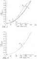
- An example of an actual display measured luminance characteristic curveis shown in Fig. 6 .
- the display characteristic curves 20describe the relationships between RGB neutral target code values (Table 1) and the computed RGB primary light intensities.
- the xyY data from Table 1are used to compute XYZ tristimulus values for the neutral targets.
- the inverse primary relationship 22is then used to compute red, green and blue intensities for the neutral targets.
- the dataare then normalized so that each channel gives an intensity of 1.0 at full white.
- the resultis a set of red, green and blue flat panel display characteristic curves 20 as shown in Fig. 7 .
- the next stepis to use the inverse primary matrix 22 and flat panel display characteristic curves 20 in the image processing chain shown in Fig. 5 .
- the chainbegins by mapping pixel-by-pixel red, green and blue image code values through a set of aim curves, such as the sRGB curves 24 shown in Fig. 8 .
- This mappingconverts sRGB image code values to red, green and blue intensities for each pixel.
- the red, green and blue intensity dataare converted to aim CIE XYZ tristimulus values using an aim primary matrix 26 that represents the intended application with a specified white point.
- the format of the aim primary matrixis usually a n x n matrix normalized to an aim white point. For RGB three primary systems, n equals 3.
- aim matriceswould be the EBU phosphor set with a CIE D65 white point or any specific aim that represents a specific gamut that you are trying to achieve for your desired white point aim.
- a chromatic adaptation transform 28may be performed to achieve the corresponding XYZ values for the flat panel display's 10 white point.
- the chromatic adaptation transform 28computes corresponding tristimulus values to insure equal color appearance between the aim and the display.
- Common chromatic adaptation transformsare the von Kries (see textbook Color Appearance Models by Mark D.
- Fig. 5shows that images can be made to achieve a color enhanced position after being processed through the steps referred to above.
- Figs. 9 and 10show results in CIELAB space of the color enhancement algorithm applied to a color target as imaged on an OLED display.
- Fig. 9is a b* vs a* vector plot showing the hue and chroma changes before and after color enhancement for the target colors.
- Fig. 10is a L* vs C* vector plot showing the lightness and chroma changes before and after color enhancement for the target colors. Note that after color enhancement, the neutral scale becomes achromatic (i.e. a* and b* are close to zero for all neutral target colors).
Landscapes
- Engineering & Computer Science (AREA)
- Physics & Mathematics (AREA)
- Theoretical Computer Science (AREA)
- General Physics & Mathematics (AREA)
- Computer Hardware Design (AREA)
- Multimedia (AREA)
- Signal Processing (AREA)
- Health & Medical Sciences (AREA)
- General Health & Medical Sciences (AREA)
- Biomedical Technology (AREA)
- Control Of Indicators Other Than Cathode Ray Tubes (AREA)
- Control Of El Displays (AREA)
- Controls And Circuits For Display Device (AREA)
- Spectrometry And Color Measurement (AREA)
- Testing Of Optical Devices Or Fibers (AREA)
- Electroluminescent Light Sources (AREA)
Description
- The invention relates generally to the field of image display technology, and in particular to processes for characterizing and driving flat panel displays such as Organic Light Emitting Diode (OLED) Displays.
- In today's digital infoimaging world, many images are previewed and manipulated on low-power, hand-held portable electronic flat panel displays. New display applications (i.e. cell phones, DVD, palm pilots, video games, GPS, etc.) impose greater design requirements and improved imaging performance than other imaging display devices used previously. Displays are intended to provide a realistic representation of the images to the viewer, thus there is a need to correct display color and tonal responses to enhance the display image quality. The color and tonal enhancement must be implemented in the display's imaging chain.
- Flat panel displays such as OLED displays have the potential for providing superior performance in brightness and color resolution, wide viewing angle, low power consumption, and compact and robust physical characteristics. However, unlike CRTs, these flat panel displays have a fixed white point and a chromatic neutral response that result from the manufacturing process, and are not adjustable. Variations in the manufacturing process result in variations in the white point and chromatic neutral and therefore unwanted variations in display color reproduction. With manufacturing processing variability and the need to increase yield to lower costs, it becomes imperative to develop robust and easy to implement color characterization and display driving techniques that accommodate for manufacturing variations.
US 4,700,218 A may be construed to disclose an automated system for adjustment of the white balance in a signal displayed on the screen of a color CRT including a device attachable to the screen of a color CRT for detecting a first value for at least one of the following signal characteristics: Contrast, brightness, red/green/blue lowlights and red/green/blue highlights in a signal displayed on the screen; a mechanism for changing the first value to a second value within the control range of the CRT; a mechanism for detecting such a second value; a mechanism for storing at least one value within the control range of the CRT for at least one of the foregoing signal characteristics; a mechanism for recovering any such stored value; and a mechanism for conforming the value of one or more of such signal characteristics to a stored value.WO 94/22270 A1 - There is provided a method according to the independent claim. Developments are set forth in the dependent claim(s).
- Preferably, there is a method of calibrating a flat panel, comprising the steps of:
- a) providing a flat panel display having an overall and individual channel adjustment for both gain and offset, and an adjustment to provide a white point for the display, the white point including color temperature, chromaticity and luminance level;
- b) displaying a first target using a low level code value for each channel of the display;
- c) sensing the luminance level of the displayed first target;
- d) adjusting the gain of the display so that the sensed luminance level matches a first predetermined aim value representing a luminance level at least 3 decades lower than a maximum luminance level;
- e) displaying a second target using intermediate code values for each channel of the display device;
- f) sensing the luminance level and chromaticities of the displayed second target;
- g) adjusting the individual channel offsets so that the luminance level matches a second predetermined aim value representing an intermediate luminance level and the chromaticities match a first set of predetermined chromaticities that represent a desired white point;
- h) displaying a third target using maximum code values for each channel of the display;
- i) sensing the luminance level and chromaticities of the displayed third target;
- j) adjusting the individual channel gains so that the luminance level matches a third predetermined aim value representing a maximum luminance level and the chromaticities match the first set of predetermined chromaticities; and k) repeating steps e) through j) a number of times until no further adjustment is required in step j).
- Preferably, the flat panel display is characterized by displaying further targets using intermediate code values for each channel of the display device; sensing the luminance level and chromaticities of the displayed further targets; and adjusting the individual channel offsets so that the luminance level matches the second predetermined aim value representing an intermediate luminance level and the chromaticities match a first set of predetermined chromaticities that represent a desired white point.
- Preferably, a method for driving a color flat panel display with RGB code values, includes the steps of:
- a) converting the RGB code values to aim RGB intensities;
- b) transforming the aim RGB intensities to CIE XYZ values at a defined aim white point;
- c) translating the CIE XYZ values to corresponding XYZ tristimulus values for the flat panel display white point;
- d) transforming the corresponding XYZ tristimulus values to display RGB intensities;
- e) converting the display RGB intensities to display drive RGB code values; and
- f) applying the display drive RGB code values to the flat panel display.
- The present invention has the advantage of correcting the multi-channel flat panel display's neutral characteristic response to be achromatic. For example, it is capable of achieving achromatic responses for any given white point. It has the further advantage that the flat panel display driving algorithm can be easily implemented with software LUTs or with digital signal processing integrated circuit technology. The flat panel display characterization data can be stored onboard and changed if necessary, thus updating the driving algorithm for aging or customization. The present invention also has the advantage of modifying the multi-channel flat panel display's color reproduction in order to achieve an aim. Using the present invention, an aim color reproduction can be achieved for any given white point. Future applications can be further advantaged using the neutral correction and color reproduction data to enhance a flat panel display's visual appearance.
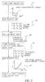
Fig. 1 is a schematic diagram of a system useful for calibrating and characterizing a flat panel display according to the present invention;Fig. 2 is a flow chart showing the flat panel white point calibration process;Fig. 3 is an example plot of the measured neutral target spectra;Fig. 4 is an example of the measured RGB primary spectra;Fig. 5 is a flow chart showing the image processing path for driving a flat panel display according to the present invention;Fig. 6 is an example plot of the measured OLED characteristic curve;Fig. 7 is an example plot of the red, green and blue OLED characteristic curves;Fig. 8 is an example plot of aim sRGB characteristic curves;Fig. 9 is a b* vs a* vector plot illustrating before and after color enhancement; andFig. 10 is an L* vs C* vector plot illustrating before and after color enhancement.- Calibrating, characterizing and driving a flat panel display according to the present invention includes three components. First the flat panel display is calibrated to a desired white point. Next, the flat panel display is characterized for chromaticity and luminance. Finally, an image processing path is provided for driving the display. Referring to
Fig. 1 , a system useful in performing the optical characterization of a colorflat panel display 10 according to the present invention is shown. According to the present invention, theflat panel display 10 is provided with electronic amplifiers to adjust each individual channel gain and offset and master adjustment controls for gain and offset. The master controls gang the individual channels together and allow simultaneous control of all channels. These controls will be used in setting the display white point for color and luminance. The components of the system include aspectral radiometer 12 with sufficient sensitivity and accuracy to measure the display spectra. A preferredspectral radiometer 12 is the PR-705 available from Photo Research, Chatsworth CA, which has provision to read the measured light output viacentral processing unit 16 or manually using its built-in display. - The system includes means to produce video signals with the appropriate timing parameters to produce targets to be displayed on the flat panel display. The targets are a series of patches with code values representing the level of the patch. The targets can be generated by a programmable signal generator 18 (such as an ASTRO Model 819 programmable signal generator) or by a
graphics card 17 in acentral processing unit 16. The targets are created such that their timing and level match the input specifications of theflat panel display 10. - An R,G,
B video switcher 14 can be used to select the signals from either thesignal generator 18 or thecentral processing unit 16. The targets can be generated in thecentral processing unit 16 using commercial available software packages such as Adobe Photo Shop. Alternatively, a custom software program can be written to produce targets using the command structure for thegraphics card 17. Another possible approach is to have the targets stored on a disk, such as a Photo CD and use the central processing display utilities to display the image of the targets. - Referring to
Fig. 2 , the calibration of the desired white point is accomplished according to the present invention as follows. A first target using a low level code value for each channel is displayed30. The luminance level of the displayed first target is sensed32 using thespectral radiometer 12 and the measured RGB values are compared34 to a first aim value representing a luminance level at least 3 decades lower than a maximum luminance level. The gain and offset of the display are then adjusted36 so that the sensed luminance level matches the first predetermined aim value. - A second target is displayed38 using intermediate code values for each channel of the display device. The luminance level and chromaticities of the displayed second target are sensed40 and compared42 with a second aim value representing an intermediate luminance level. The individual channel gains and offsets are then adjusted44 so that the luminance level matches the second predetermined aim value and the chromaticities match a first set of predetermined chromaticities that represent a desired white point.
- A third target using maximum code values for each channel of the display is displayed46. The luminance level and chromaticities of the displayed third target are sensed48 and compared50 with a third aim value representing the maximum luminance level. The individual channel gains and offsets are then adjusted52 so that the luminance level matches a third predetermined aim value and the chromaticities match the first set of predetermined chromaticities. The above steps are repeated until all three aims are achieved.
- The chromaticity and luminance characterization of the multi-channel flat panel display begins by measuring a series of test patterns (neutral targets) with equal signals for all channels. Luminance and chromaticity data are calculated from the spectrum of each measured neutral target. An example of one measured neutral target spectrum for an OLED is shown in
Fig. 3 . The 1931 CIE chromaticity specification, therefore the x, y, Y were reported and displayed as illustrated in Table 1.Table 1 Neutral Target Code Value Y(cd/m2) CIE31x CIE31y 0 4.08E-01 0.2778 0.5252 10 4.77E-01 0.2706 0.4714 20 6.95E-01 0.271 0.4332 30 1.07E+00 0.2753 0.4032 40 1.65E+00 0.283 0.3807 50 2.50E+00 0.2925 0.3647 65 4.39E+00 0.3053 0.3489 80 7.03E+00 0.3152 0.3399 95 1.04E+01 0.3215 0.3342 115 1.58E+01 0.3272 0.3297 135 2.21E+01 0.3307 0.3273 155 2.91E+01 0.3321 0.3255 175 3.66E+01 0.3305 0.3244 200 4.63E+01 0.3236 0.3236 225 5.63E+01 0.3131 0.3232 245 6.46E+01 0.3048 0.3236 255 6.89E+01 0.3019 0.3243 - Next, the color primaries were set to their maximum level and measured.
Fig. 4 is an example of the OLED flat panel display measured RGB spectra. Chromaticity and luminance are calculated from the spectra of each measured primary and are shown in Table 2.Table 2 Color Primary Y (cd/m2) CIE31x CIE31y Red 34.8 0.6534 0.3412 Green 21.6 0.2779 0.6521 Blue 22.8 0.1535 0.1965 - The primary response data from Table 2 are converted to 1931 CIE XYZ tristimulus values for each red, green and blue primary. These primary XYZ values are used in
equation 1 below to relate primary intensity (e.g. Ri,Gi,Bi) to 1931 CIE tristimulus values (XYZ) for any color stimulus. The general form of this equation for a three primary system is:
- The coefficients XR, YR, and ZR are obtained from the xyY red primary data from Table 2 above. Similarly the green and blue coefficients are obtained from the green and blue primary data from Table 2. Typically the full red, green and blue intensities of a full drive white are normalized to produce the desired tristimulus values for the aim illuminant. In practice, the nine coefficients form a 3x3 matrix, which is very commonly used for this relationship. Also the
inverse 22 of the above equations are needed to convert from tristimulus values to RGB intensities. The general form of this inverse relationship is more easily shown by the following matrix equation:
- Referring to
Fig. 5 , the above characterization data are used to compute the flat panel displaycharacteristic curves 20. An example of an actual display measured luminance characteristic curve is shown inFig. 6 . The displaycharacteristic curves 20 describe the relationships between RGB neutral target code values (Table 1) and the computed RGB primary light intensities. In order to obtain these displaycharacteristic curves 20, the xyY data from Table 1 are used to compute XYZ tristimulus values for the neutral targets. The inverseprimary relationship 22 is then used to compute red, green and blue intensities for the neutral targets. The data are then normalized so that each channel gives an intensity of 1.0 at full white. The result is a set of red, green and blue flat panel displaycharacteristic curves 20 as shown inFig. 7 . - The next step is to use the inverse
primary matrix 22 and flat panel displaycharacteristic curves 20 in the image processing chain shown inFig. 5 . The chain begins by mapping pixel-by-pixel red, green and blue image code values through a set of aim curves, such as the sRGB curves24 shown inFig. 8 . This mapping converts sRGB image code values to red, green and blue intensities for each pixel. The red, green and blue intensity data are converted to aim CIE XYZ tristimulus values using an aimprimary matrix 26 that represents the intended application with a specified white point. The format of the aim primary matrix is usually a n x n matrix normalized to an aim white point. For RGB three primary systems, n equals 3. Examples of aim matrices would be the EBU phosphor set with a CIE D65 white point or any specific aim that represents a specific gamut that you are trying to achieve for your desired white point aim. If theflat panel display 10 is not capable of achieving the aim white point tristimulus values, a chromatic adaptation transform28 may be performed to achieve the corresponding XYZ values for the flat panel display's10 white point. The chromatic adaptation transform28 computes corresponding tristimulus values to insure equal color appearance between the aim and the display. Common chromatic adaptation transforms are the von Kries (see textbookColor Appearance Models by Mark D. Fairchild, Addison-Wesley, November 1997) and the Bradford equations (seeLuo, et al., "the LLAB(1:c) colour model" Color Res. Appl. 21, 412-429 (1996)). Alternatively, if the white point is very far away from the aim point in chromaticity space, it may not be desirable to perform the chromatic adaptation transform. In this case, one may skip the chromatic adaptation transform step. This allows one to achieve the aim neutral chromaticities at the expense of reduced luminance dynamic range. - Next, it is necessary to convert those corresponding tristimulus values for each image pixel to flat panel display red, green and blue intensities using the inverse
primary matrix 22 as shown inequation 2. The last step inFig. 5 is to map those red, green and blue intensities through the flat panel display characteristic curves20 (Fig. 7 ) to produce red, green and blue code values that are used to drive theflat panel display 10. - In summary,
Fig. 5 shows that images can be made to achieve a color enhanced position after being processed through the steps referred to above.Figs. 9 and 10 show results in CIELAB space of the color enhancement algorithm applied to a color target as imaged on an OLED display.Fig. 9 is a b* vs a* vector plot showing the hue and chroma changes before and after color enhancement for the target colors.Fig. 10 is a L* vs C* vector plot showing the lightness and chroma changes before and after color enhancement for the target colors. Note that after color enhancement, the neutral scale becomes achromatic (i.e. a* and b* are close to zero for all neutral target colors).


Claims (2)
- A method of calibrating a flat panel display (10), comprising the steps of:a) providing the flat panel display having an overall and individual video signal channel adjustment for both gain and offset and an adjustment to provide a white point for the display, the white point including color temperature, chromaticity and luminance level;b) displaying (30) a first target using a low-level code value for each video signal channel of the flat panel display;c) sensing (32) the luminance level of the displayed first target and measuring the RGB values;d) comparing (34) the measured RGB values to a first predetermined aim value representing a luminance level at least 3 decades lower than a maximum luminance level;e) adjusting (36), if the first target is not equal to the first aim value, the gain and offset of the flat panel display so that the sensed luminance level matches the first predetermined aim value;f) displaying (38), if the first target is equal to the first aim value or following step e), a second target using intermediate code values for each video signal channel of the flat panel display;g) sensing (40) the luminance level and chromaticities of the displayed second target;h) comparing (42) the luminance level and chromaticities of the displayed second target to a second predetermined aim value representing an intermediate luminance level;i) adjusting (44), if the second target is not equal to the second aim value, the individual video signal channel gains and offsets so that the luminance level matches the second predetermined aim value and the chromaticities match a first set of predetermined chromaticities that represent a desired white point;j) displaying (46), if the second target is equal to the second aim value, a third target using maximum code values for each video signal channel of the flat panel display;k) sensing (48) the luminance level and chromaticities of the displayed third target;l) comparing (50) the luminance level and chromaticities of the displayed third target to a third predetermined aim value representing the maximum luminance level,m) adjusting (52), if the third target is not equal to the third aim value, the individual video signal channel gains and offsets so that the luminance level matches the third predetermined aim value, and that both the maximum luminance level and the chromaticities match the first set of predetermined chromaticities; andn) repeating steps f) through m) a number of times until the third target is equal to the third aim value.
- The method claimed in claim 1, further comprising the steps of:displaying a further target using intermediate code values for each video signal channel of the flat panel display;sensing the luminance level and chromaticities of the displayed further targets; andadjusting the individual video signal channel offsets so that the luminance level matches the second predetermined aim value representing an intermediate luminance level and the chromaticities match a first set of predetermined chromaticities that represent a desired white point.
Applications Claiming Priority (4)
| Application Number | Priority Date | Filing Date | Title |
|---|---|---|---|
| US950245 | 1978-10-10 | ||
| US887152 | 2001-06-22 | ||
| US09/887,152US20030025688A1 (en) | 2001-06-22 | 2001-06-22 | Method for calibrating, characterizing and driving a color flat panel display |
| US09/950,245US6677958B2 (en) | 2001-06-22 | 2001-09-10 | Method for calibrating, characterizing and driving a color flat panel display |
Publications (3)
| Publication Number | Publication Date |
|---|---|
| EP1271465A2 EP1271465A2 (en) | 2003-01-02 |
| EP1271465A3 EP1271465A3 (en) | 2009-08-19 |
| EP1271465B1true EP1271465B1 (en) | 2019-03-20 |
Family
ID=27128825
Family Applications (1)
| Application Number | Title | Priority Date | Filing Date |
|---|---|---|---|
| EP02077262.0AExpired - LifetimeEP1271465B1 (en) | 2001-06-22 | 2002-06-10 | Method for calibrating, characterizing and driving a color flat panel display |
Country Status (3)
| Country | Link |
|---|---|
| US (1) | US6677958B2 (en) |
| EP (1) | EP1271465B1 (en) |
| JP (1) | JP4721610B2 (en) |
Families Citing this family (42)
| Publication number | Priority date | Publication date | Assignee | Title |
|---|---|---|---|---|
| KR100419214B1 (en)* | 2001-02-24 | 2004-02-19 | 삼성전자주식회사 | Apparatus and method for transformation of color temperature in color display system |
| JP3719411B2 (en)* | 2001-05-31 | 2005-11-24 | セイコーエプソン株式会社 | Image display system, projector, program, information storage medium, and image processing method |
| US7145529B2 (en)* | 2001-08-23 | 2006-12-05 | Koninklijke Philips Electronics, N.V. | Method and drive means for color correction in an organic electroluminescent device |
| JP2004151167A (en)* | 2002-10-29 | 2004-05-27 | Fuji Photo Film Co Ltd | Method and system for image correction |
| US7907154B2 (en)* | 2003-06-04 | 2011-03-15 | Radiant Imaging, Inc. | Method and apparatus for on-site calibration of visual displays |
| US7911485B2 (en)* | 2003-06-04 | 2011-03-22 | Radiam Imaging, Inc. | Method and apparatus for visual display calibration system |
| US7312779B1 (en)* | 2003-09-23 | 2007-12-25 | Northrop Grumman Corporation | Method of color calibration for transmissive displays |
| EP1671314A1 (en)* | 2003-09-30 | 2006-06-21 | Koninklijke Philips Electronics N.V. | Multiple primary color display system and method of display using multiple primary colors |
| JP3751621B2 (en)* | 2003-10-23 | 2006-03-01 | 株式会社ナナオ | Display characteristic calibration method, display characteristic calibration apparatus, and computer program |
| JP5073920B2 (en)* | 2003-12-23 | 2012-11-14 | バルコ・ナムローゼ・フエンノートシャップ | Calibration method for calibrating fixed format light emitting display device and fixed format light emitting display device |
| JP4122381B2 (en)* | 2003-12-24 | 2008-07-23 | 国立大学法人静岡大学 | Display device color display method |
| JP4855648B2 (en)* | 2004-03-30 | 2012-01-18 | グローバル・オーエルイーディー・テクノロジー・リミテッド・ライアビリティ・カンパニー | Organic EL display device |
| US20050253777A1 (en)* | 2004-05-12 | 2005-11-17 | E Ink Corporation | Tiled displays and methods for driving same |
| KR100995040B1 (en) | 2004-06-11 | 2010-11-19 | 엘지전자 주식회사 | AC bias and gain adjustment method |
| US7218358B2 (en)* | 2004-06-15 | 2007-05-15 | Coretronic Corporation | Method and apparatus for calibrating color temperature of color display devices |
| US7576733B2 (en)* | 2004-07-12 | 2009-08-18 | Gtech Rhode Island Corporation | Touch screen image setting frame |
| US20060077135A1 (en)* | 2004-10-08 | 2006-04-13 | Eastman Kodak Company | Method for compensating an OLED device for aging |
| US7301618B2 (en)* | 2005-03-29 | 2007-11-27 | Eastman Kodak Company | Method and apparatus for uniformity and brightness correction in an OLED display |
| KR100710302B1 (en)* | 2005-05-17 | 2007-04-23 | 엘지전자 주식회사 | Apparatus and method for color correction of a display device |
| TWI309028B (en)* | 2005-06-13 | 2009-04-21 | Novatek Microelectronics Corp | Method for calibrating a flat panel display |
| US20070035536A1 (en)* | 2005-08-11 | 2007-02-15 | Eastman Kodak Company | Display calibration method for optimum angular performance |
| KR100763235B1 (en)* | 2005-10-21 | 2007-10-04 | 삼성전자주식회사 | Method and device to calibrate color characteristics of monitor |
| TW200723895A (en)* | 2005-12-09 | 2007-06-16 | Inventec Corp | Display color temperature inspection/calibration device and method |
| US7876970B2 (en)* | 2006-01-13 | 2011-01-25 | Qualcomm Incorporated | Method and apparatus for white balancing digital images |
| JP5449641B2 (en)* | 2006-04-17 | 2014-03-19 | グローバル・オーエルイーディー・テクノロジー・リミテッド・ライアビリティ・カンパニー | Display device |
| US7893975B2 (en)* | 2006-10-13 | 2011-02-22 | Apple Inc. | System and method for processing images using predetermined tone reproduction curves |
| US7835569B2 (en)* | 2006-10-13 | 2010-11-16 | Apple Inc. | System and method for raw image processing using conversion matrix interpolated from predetermined camera characterization matrices |
| US7773127B2 (en)* | 2006-10-13 | 2010-08-10 | Apple Inc. | System and method for RAW image processing |
| US8525762B2 (en)* | 2006-11-16 | 2013-09-03 | Innolux Corporation | Systems and methods for adjusting display parameters of an active matrix organic light emitting diode panel |
| TW200823562A (en)* | 2006-11-27 | 2008-06-01 | Innolux Display Corp | Liquid crystal display |
| US7884832B2 (en) | 2007-04-13 | 2011-02-08 | Global Oled Technology Llc | Calibrating RGBW displays |
| WO2008143618A1 (en)* | 2007-05-22 | 2008-11-27 | Thomson Licensing | Method and system for prediction of gamma characteristics for a display |
| US20100201667A1 (en)* | 2007-06-18 | 2010-08-12 | Bongsun Lee | Method and system for display characterization and content calibration |
| TWI402823B (en)* | 2009-04-03 | 2013-07-21 | Himax Media Solutions Inc | Color adjustment method |
| JP6082953B2 (en)* | 2012-04-16 | 2017-02-22 | 株式会社Joled | Manufacturing method of display device |
| KR20150006723A (en)* | 2013-07-09 | 2015-01-19 | 삼성디스플레이 주식회사 | Method and apparatus for controlling optical quantities of organic light emission display device |
| EP2955711B1 (en) | 2014-05-09 | 2018-11-21 | Ams Ag | Method for calibrating a color space transformation, method for color space transformation and color control system |
| US9478157B2 (en) | 2014-11-17 | 2016-10-25 | Apple Inc. | Ambient light adaptive displays |
| US9530362B2 (en) | 2014-12-23 | 2016-12-27 | Apple Inc. | Ambient light adaptive displays with paper-like appearance |
| JP6520578B2 (en)* | 2015-08-31 | 2019-05-29 | 株式会社Jvcケンウッド | Image processing apparatus and display determination method |
| CN109243365B (en)* | 2018-09-20 | 2021-03-16 | 合肥鑫晟光电科技有限公司 | Display method and display device of display device |
| TWI761968B (en)* | 2020-09-28 | 2022-04-21 | 緯創資通股份有限公司 | Color-calibration system and color-calibration method for display panel |
Family Cites Families (18)
| Publication number | Priority date | Publication date | Assignee | Title |
|---|---|---|---|---|
| JPH0583660A (en)* | 1991-09-24 | 1993-04-02 | Toshiba Corp | Electronic device automatic adjustment circuit |
| US5371537A (en)* | 1991-10-31 | 1994-12-06 | Eastman Kodak Company | Method and apparatus for automatically calibrating a CRT display |
| US5512961A (en)* | 1993-03-24 | 1996-04-30 | Apple Computer, Inc. | Method and system of achieving accurate white point setting of a CRT display |
| US5499040A (en)* | 1994-06-27 | 1996-03-12 | Radius Inc. | Method and apparatus for display calibration and control |
| US5694227A (en)* | 1994-07-15 | 1997-12-02 | Apple Computer, Inc. | Method and apparatus for calibrating and adjusting a color imaging system |
| US5528339A (en)* | 1994-08-26 | 1996-06-18 | Eastman Kodak Company | Color image reproduction of scenes with color enhancement and preferential tone mapping |
| US5881209A (en)* | 1994-09-13 | 1999-03-09 | Apple Computer, Inc. | Method and system for automatically generating printer profiles |
| US6108008A (en)* | 1994-09-22 | 2000-08-22 | Canon Kabushiki Kaisha | Color image mapping within output device reproduction range |
| US5754222A (en)* | 1996-03-08 | 1998-05-19 | Eastman Kodak Company | Visual characterization using display model |
| US6320980B1 (en)* | 1995-10-02 | 2001-11-20 | Canon Kabushiki Kaisha | Image processing apparatus and method, and recording medium |
| US6222932B1 (en)* | 1997-06-27 | 2001-04-24 | International Business Machines Corporation | Automatic adjustment of image watermark strength based on computed image texture |
| US6160644A (en)* | 1998-03-30 | 2000-12-12 | Seiko Epson Corporation | Scanner calibration technique to overcome tone inversion |
| WO1999053693A1 (en)* | 1998-04-15 | 1999-10-21 | Mitsubishi Denki Kabushiki Kaisha | Multivision system, color calibration method and display |
| US6023264A (en)* | 1998-04-24 | 2000-02-08 | Adobe Systems Incorporated | Method to estimate the white point on a display device |
| US6205244B1 (en)* | 1998-06-23 | 2001-03-20 | Intel Corporation | Method for imager device color calibration utilizing light-emitting diodes or other spectral light sources |
| JP3433406B2 (en)* | 1999-10-18 | 2003-08-04 | インターナショナル・ビジネス・マシーンズ・コーポレーション | White point adjustment method, color image processing method, white point adjustment device, and liquid crystal display device |
| US6522313B1 (en)* | 2000-09-13 | 2003-02-18 | Eastman Kodak Company | Calibration of softcopy displays for imaging workstations |
| US6320325B1 (en)* | 2000-11-06 | 2001-11-20 | Eastman Kodak Company | Emissive display with luminance feedback from a representative pixel |
- 2001
- 2001-09-10USUS09/950,245patent/US6677958B2/ennot_activeExpired - Lifetime
- 2002
- 2002-06-10EPEP02077262.0Apatent/EP1271465B1/ennot_activeExpired - Lifetime
- 2002-06-24JPJP2002182915Apatent/JP4721610B2/ennot_activeExpired - Lifetime
Non-Patent Citations (1)
| Title |
|---|
| None* |
Also Published As
| Publication number | Publication date |
|---|---|
| JP4721610B2 (en) | 2011-07-13 |
| EP1271465A2 (en) | 2003-01-02 |
| JP2003150099A (en) | 2003-05-21 |
| EP1271465A3 (en) | 2009-08-19 |
| US20030048264A1 (en) | 2003-03-13 |
| US6677958B2 (en) | 2004-01-13 |
Similar Documents
| Publication | Publication Date | Title |
|---|---|---|
| EP1271465B1 (en) | Method for calibrating, characterizing and driving a color flat panel display | |
| EP2135234B1 (en) | Calibrating rgbw displays | |
| US5561459A (en) | Automatic profile generation for a self-calibrating color display | |
| Berns | Methods for characterizing CRT displays | |
| US8587603B2 (en) | Method and apparatus for improved color correction | |
| KR100834762B1 (en) | Color Gamut Mapping Method and Apparatus | |
| KR100710302B1 (en) | Apparatus and method for color correction of a display device | |
| US5512961A (en) | Method and system of achieving accurate white point setting of a CRT display | |
| JP4829110B2 (en) | Conversion of 3-color input signal to more colors | |
| US20140002481A1 (en) | Method for converting data, display device, computing device and program incorporating same, and method for optimising coefficients and device and program incorporating same | |
| US20080252797A1 (en) | Method for input-signal transformation for rgbw displays with variable w color | |
| US6522313B1 (en) | Calibration of softcopy displays for imaging workstations | |
| CN101217674A (en) | Apparatus and method for ambient light adaptive color correction | |
| US11024255B2 (en) | Method and apparatus for color calibration for reduced motion-induced color breakup | |
| US20030025688A1 (en) | Method for calibrating, characterizing and driving a color flat panel display | |
| CN112885300B (en) | Panel calibration using multiple nonlinear models | |
| KR100565266B1 (en) | Color temperature gamma correction method of LCD | |
| KR20020024668A (en) | White Point and Inverse Gamma Selection Method from Color Modeling Process for Plasma Display Panel | |
| US20060227148A1 (en) | Visual determination of gamma for softcopy display | |
| US20110249040A1 (en) | Color signal processing apparatus and color signal processing method | |
| CN112802418B (en) | Panel color temperature matching correction method and system | |
| MacDonald | Colour in visual displays | |
| JP2001036758A (en) | Color correction processing method and device therefor | |
| MacDonald | Assessment of monitor calibration for Internet imaging | |
| CN113920961A (en) | Display device and color adjustment method |
Legal Events
| Date | Code | Title | Description |
|---|---|---|---|
| PUAI | Public reference made under article 153(3) epc to a published international application that has entered the european phase | Free format text:ORIGINAL CODE: 0009012 | |
| AK | Designated contracting states | Kind code of ref document:A2 Designated state(s):AT BE CH CY DE DK ES FI FR GB GR IE IT LI LU MC NL PT SE TR | |
| AX | Request for extension of the european patent | Free format text:AL;LT;LV;MK;RO;SI | |
| PUAL | Search report despatched | Free format text:ORIGINAL CODE: 0009013 | |
| AK | Designated contracting states | Kind code of ref document:A3 Designated state(s):AT BE CH CY DE DK ES FI FR GB GR IE IT LI LU MC NL PT SE TR | |
| AX | Request for extension of the european patent | Extension state:AL LT LV MK RO SI | |
| 17P | Request for examination filed | Effective date:20100209 | |
| RAP1 | Party data changed (applicant data changed or rights of an application transferred) | Owner name:GLOBAL OLED TECHNOLOGY LLC | |
| AKX | Designation fees paid | Designated state(s):DE FR GB | |
| 17Q | First examination report despatched | Effective date:20100701 | |
| RAP1 | Party data changed (applicant data changed or rights of an application transferred) | Owner name:GLOBAL OLED TECHNOLOGY LLC | |
| STAA | Information on the status of an ep patent application or granted ep patent | Free format text:STATUS: EXAMINATION IS IN PROGRESS | |
| GRAP | Despatch of communication of intention to grant a patent | Free format text:ORIGINAL CODE: EPIDOSNIGR1 | |
| STAA | Information on the status of an ep patent application or granted ep patent | Free format text:STATUS: GRANT OF PATENT IS INTENDED | |
| INTG | Intention to grant announced | Effective date:20180418 | |
| RAP1 | Party data changed (applicant data changed or rights of an application transferred) | Owner name:GLOBAL OLED TECHNOLOGY LLC | |
| GRAS | Grant fee paid | Free format text:ORIGINAL CODE: EPIDOSNIGR3 | |
| GRAJ | Information related to disapproval of communication of intention to grant by the applicant or resumption of examination proceedings by the epo deleted | Free format text:ORIGINAL CODE: EPIDOSDIGR1 | |
| GRAL | Information related to payment of fee for publishing/printing deleted | Free format text:ORIGINAL CODE: EPIDOSDIGR3 | |
| STAA | Information on the status of an ep patent application or granted ep patent | Free format text:STATUS: EXAMINATION IS IN PROGRESS | |
| INTC | Intention to grant announced (deleted) | ||
| GRAP | Despatch of communication of intention to grant a patent | Free format text:ORIGINAL CODE: EPIDOSNIGR1 | |
| STAA | Information on the status of an ep patent application or granted ep patent | Free format text:STATUS: GRANT OF PATENT IS INTENDED | |
| GRAJ | Information related to disapproval of communication of intention to grant by the applicant or resumption of examination proceedings by the epo deleted | Free format text:ORIGINAL CODE: EPIDOSDIGR1 | |
| GRAL | Information related to payment of fee for publishing/printing deleted | Free format text:ORIGINAL CODE: EPIDOSDIGR3 | |
| STAA | Information on the status of an ep patent application or granted ep patent | Free format text:STATUS: EXAMINATION IS IN PROGRESS | |
| INTG | Intention to grant announced | Effective date:20181030 | |
| INTC | Intention to grant announced (deleted) | ||
| GRAP | Despatch of communication of intention to grant a patent | Free format text:ORIGINAL CODE: EPIDOSNIGR1 | |
| STAA | Information on the status of an ep patent application or granted ep patent | Free format text:STATUS: GRANT OF PATENT IS INTENDED | |
| INTG | Intention to grant announced | Effective date:20190117 | |
| GRAA | (expected) grant | Free format text:ORIGINAL CODE: 0009210 | |
| STAA | Information on the status of an ep patent application or granted ep patent | Free format text:STATUS: THE PATENT HAS BEEN GRANTED | |
| AK | Designated contracting states | Kind code of ref document:B1 Designated state(s):DE FR GB | |
| REG | Reference to a national code | Ref country code:GB Ref legal event code:FG4D | |
| REG | Reference to a national code | Ref country code:DE Ref legal event code:R096 Ref document number:60249827 Country of ref document:DE | |
| REG | Reference to a national code | Ref country code:DE Ref legal event code:R097 Ref document number:60249827 Country of ref document:DE | |
| PLBE | No opposition filed within time limit | Free format text:ORIGINAL CODE: 0009261 | |
| STAA | Information on the status of an ep patent application or granted ep patent | Free format text:STATUS: NO OPPOSITION FILED WITHIN TIME LIMIT | |
| 26N | No opposition filed | Effective date:20200102 | |
| PGFP | Annual fee paid to national office [announced via postgrant information from national office to epo] | Ref country code:FR Payment date:20210622 Year of fee payment:20 Ref country code:DE Payment date:20210618 Year of fee payment:20 | |
| PGFP | Annual fee paid to national office [announced via postgrant information from national office to epo] | Ref country code:GB Payment date:20210625 Year of fee payment:20 | |
| REG | Reference to a national code | Ref country code:DE Ref legal event code:R071 Ref document number:60249827 Country of ref document:DE | |
| REG | Reference to a national code | Ref country code:GB Ref legal event code:PE20 Expiry date:20220609 | |
| PG25 | Lapsed in a contracting state [announced via postgrant information from national office to epo] | Ref country code:GB Free format text:LAPSE BECAUSE OF EXPIRATION OF PROTECTION Effective date:20220609 |