EP1269639B1 - Interference detection, identification, extraction and reporting - Google Patents
Interference detection, identification, extraction and reportingDownload PDFInfo
- Publication number
- EP1269639B1 EP1269639B1EP01924805AEP01924805AEP1269639B1EP 1269639 B1EP1269639 B1EP 1269639B1EP 01924805 AEP01924805 AEP 01924805AEP 01924805 AEP01924805 AEP 01924805AEP 1269639 B1EP1269639 B1EP 1269639B1
- Authority
- EP
- European Patent Office
- Prior art keywords
- narrowband
- signal
- threshold
- block
- interference
- Prior art date
- Legal status (The legal status is an assumption and is not a legal conclusion. Google has not performed a legal analysis and makes no representation as to the accuracy of the status listed.)
- Expired - Lifetime
Links
- 238000000605extractionMethods0.000titledescription4
- 238000001514detection methodMethods0.000title1
- 238000004891communicationMethods0.000claimsdescription61
- 238000000034methodMethods0.000claimsdescription39
- 238000001914filtrationMethods0.000claimsdescription20
- 230000004044responseEffects0.000claimsdescription12
- 230000002238attenuated effectEffects0.000claimsdescription4
- 230000003247decreasing effectEffects0.000claims2
- 238000001228spectrumMethods0.000description29
- 230000006870functionEffects0.000description17
- 238000012360testing methodMethods0.000description16
- 230000015654memoryEffects0.000description14
- 230000003044adaptive effectEffects0.000description13
- 238000010586diagramMethods0.000description9
- 238000012545processingMethods0.000description7
- 230000008859changeEffects0.000description6
- 230000008569processEffects0.000description6
- 238000005562fadingMethods0.000description4
- 238000005259measurementMethods0.000description4
- 230000009471actionEffects0.000description3
- 230000002452interceptive effectEffects0.000description3
- 238000010408sweepingMethods0.000description3
- 238000004458analytical methodMethods0.000description2
- 230000002939deleterious effectEffects0.000description2
- 230000000694effectsEffects0.000description2
- 238000012986modificationMethods0.000description2
- 230000004048modificationEffects0.000description2
- 238000002360preparation methodMethods0.000description2
- JBRZTFJDHDCESZ-UHFFFAOYSA-NAsGaChemical compound[As]#[Ga]JBRZTFJDHDCESZ-UHFFFAOYSA-N0.000description1
- 229910001218Gallium arsenideInorganic materials0.000description1
- 230000008901benefitEffects0.000description1
- 230000005540biological transmissionEffects0.000description1
- 230000015556catabolic processEffects0.000description1
- 230000001413cellular effectEffects0.000description1
- 239000000470constituentSubstances0.000description1
- 238000006731degradation reactionMethods0.000description1
- 238000005516engineering processMethods0.000description1
- 239000004065semiconductorSubstances0.000description1
- 230000003595spectral effectEffects0.000description1
Images


Classifications
- H—ELECTRICITY
- H04—ELECTRIC COMMUNICATION TECHNIQUE
- H04W—WIRELESS COMMUNICATION NETWORKS
- H04W72/00—Local resource management
- H04W72/50—Allocation or scheduling criteria for wireless resources
- H04W72/54—Allocation or scheduling criteria for wireless resources based on quality criteria
- H04W72/541—Allocation or scheduling criteria for wireless resources based on quality criteria using the level of interference
- H—ELECTRICITY
- H04—ELECTRIC COMMUNICATION TECHNIQUE
- H04B—TRANSMISSION
- H04B7/00—Radio transmission systems, i.e. using radiation field
- H04B7/005—Control of transmission; Equalising
- H—ELECTRICITY
- H04—ELECTRIC COMMUNICATION TECHNIQUE
- H04B—TRANSMISSION
- H04B1/00—Details of transmission systems, not covered by a single one of groups H04B3/00 - H04B13/00; Details of transmission systems not characterised by the medium used for transmission
- H04B1/06—Receivers
- H04B1/10—Means associated with receiver for limiting or suppressing noise or interference
- H04B1/1027—Means associated with receiver for limiting or suppressing noise or interference assessing signal quality or detecting noise/interference for the received signal
- H04B1/1036—Means associated with receiver for limiting or suppressing noise or interference assessing signal quality or detecting noise/interference for the received signal with automatic suppression of narrow band noise or interference, e.g. by using tuneable notch filters
- H—ELECTRICITY
- H04—ELECTRIC COMMUNICATION TECHNIQUE
- H04B—TRANSMISSION
- H04B1/00—Details of transmission systems, not covered by a single one of groups H04B3/00 - H04B13/00; Details of transmission systems not characterised by the medium used for transmission
- H04B1/69—Spread spectrum techniques
- H04B1/707—Spread spectrum techniques using direct sequence modulation
- H04B1/7097—Interference-related aspects
- H04B1/71—Interference-related aspects the interference being narrowband interference
- H—ELECTRICITY
- H04—ELECTRIC COMMUNICATION TECHNIQUE
- H04B—TRANSMISSION
- H04B1/00—Details of transmission systems, not covered by a single one of groups H04B3/00 - H04B13/00; Details of transmission systems not characterised by the medium used for transmission
- H04B1/69—Spread spectrum techniques
- H04B1/707—Spread spectrum techniques using direct sequence modulation
- H04B1/7097—Interference-related aspects
- H04B1/7103—Interference-related aspects the interference being multiple access interference
- H—ELECTRICITY
- H04—ELECTRIC COMMUNICATION TECHNIQUE
- H04B—TRANSMISSION
- H04B15/00—Suppression or limitation of noise or interference
- H—ELECTRICITY
- H04—ELECTRIC COMMUNICATION TECHNIQUE
- H04W—WIRELESS COMMUNICATION NETWORKS
- H04W24/00—Supervisory, monitoring or testing arrangements
- H—ELECTRICITY
- H04—ELECTRIC COMMUNICATION TECHNIQUE
- H04W—WIRELESS COMMUNICATION NETWORKS
- H04W24/00—Supervisory, monitoring or testing arrangements
- H04W24/02—Arrangements for optimising operational condition
- H—ELECTRICITY
- H04—ELECTRIC COMMUNICATION TECHNIQUE
- H04W—WIRELESS COMMUNICATION NETWORKS
- H04W24/00—Supervisory, monitoring or testing arrangements
- H04W24/04—Arrangements for maintaining operational condition
- H—ELECTRICITY
- H04—ELECTRIC COMMUNICATION TECHNIQUE
- H04W—WIRELESS COMMUNICATION NETWORKS
- H04W24/00—Supervisory, monitoring or testing arrangements
- H04W24/08—Testing, supervising or monitoring using real traffic
- H—ELECTRICITY
- H04—ELECTRIC COMMUNICATION TECHNIQUE
- H04W—WIRELESS COMMUNICATION NETWORKS
- H04W24/00—Supervisory, monitoring or testing arrangements
- H04W24/10—Scheduling measurement reports ; Arrangements for measurement reports
- H—ELECTRICITY
- H04—ELECTRIC COMMUNICATION TECHNIQUE
- H04W—WIRELESS COMMUNICATION NETWORKS
- H04W28/00—Network traffic management; Network resource management
- H04W28/02—Traffic management, e.g. flow control or congestion control
- H04W28/04—Error control
- H—ELECTRICITY
- H04—ELECTRIC COMMUNICATION TECHNIQUE
- H04W—WIRELESS COMMUNICATION NETWORKS
- H04W28/00—Network traffic management; Network resource management
- H04W28/16—Central resource management; Negotiation of resources or communication parameters, e.g. negotiating bandwidth or QoS [Quality of Service]
- H04W28/18—Negotiating wireless communication parameters
- H04W28/20—Negotiating bandwidth
- H—ELECTRICITY
- H04—ELECTRIC COMMUNICATION TECHNIQUE
- H04W—WIRELESS COMMUNICATION NETWORKS
- H04W52/00—Power management, e.g. Transmission Power Control [TPC] or power classes
- H04W52/04—Transmission power control [TPC]
- H04W52/18—TPC being performed according to specific parameters
- H04W52/24—TPC being performed according to specific parameters using SIR [Signal to Interference Ratio] or other wireless path parameters
- H04W52/243—TPC being performed according to specific parameters using SIR [Signal to Interference Ratio] or other wireless path parameters taking into account interferences
- H—ELECTRICITY
- H04—ELECTRIC COMMUNICATION TECHNIQUE
- H04W—WIRELESS COMMUNICATION NETWORKS
- H04W52/00—Power management, e.g. Transmission Power Control [TPC] or power classes
- H04W52/04—Transmission power control [TPC]
- H04W52/18—TPC being performed according to specific parameters
- H04W52/24—TPC being performed according to specific parameters using SIR [Signal to Interference Ratio] or other wireless path parameters
- H04W52/245—TPC being performed according to specific parameters using SIR [Signal to Interference Ratio] or other wireless path parameters taking into account received signal strength
- H—ELECTRICITY
- H04—ELECTRIC COMMUNICATION TECHNIQUE
- H04W—WIRELESS COMMUNICATION NETWORKS
- H04W72/00—Local resource management
- H04W72/04—Wireless resource allocation
- H04W72/044—Wireless resource allocation based on the type of the allocated resource
- H04W72/0453—Resources in frequency domain, e.g. a carrier in FDMA
- H—ELECTRICITY
- H04—ELECTRIC COMMUNICATION TECHNIQUE
- H04W—WIRELESS COMMUNICATION NETWORKS
- H04W72/00—Local resource management
- H04W72/50—Allocation or scheduling criteria for wireless resources
- H04W72/54—Allocation or scheduling criteria for wireless resources based on quality criteria
- H04W72/542—Allocation or scheduling criteria for wireless resources based on quality criteria using measured or perceived quality
- H—ELECTRICITY
- H04—ELECTRIC COMMUNICATION TECHNIQUE
- H04W—WIRELESS COMMUNICATION NETWORKS
- H04W88/00—Devices specially adapted for wireless communication networks, e.g. terminals, base stations or access point devices
- H04W88/02—Terminal devices
- H—ELECTRICITY
- H04—ELECTRIC COMMUNICATION TECHNIQUE
- H04W—WIRELESS COMMUNICATION NETWORKS
- H04W88/00—Devices specially adapted for wireless communication networks, e.g. terminals, base stations or access point devices
- H04W88/08—Access point devices
- H—ELECTRICITY
- H04—ELECTRIC COMMUNICATION TECHNIQUE
- H04B—TRANSMISSION
- H04B1/00—Details of transmission systems, not covered by a single one of groups H04B3/00 - H04B13/00; Details of transmission systems not characterised by the medium used for transmission
- H04B1/06—Receivers
- H04B1/10—Means associated with receiver for limiting or suppressing noise or interference
- H04B1/1027—Means associated with receiver for limiting or suppressing noise or interference assessing signal quality or detecting noise/interference for the received signal
- H04B2001/1063—Means associated with receiver for limiting or suppressing noise or interference assessing signal quality or detecting noise/interference for the received signal using a notch filter
- H—ELECTRICITY
- H04—ELECTRIC COMMUNICATION TECHNIQUE
- H04B—TRANSMISSION
- H04B2201/00—Indexing scheme relating to details of transmission systems not covered by a single group of H04B3/00 - H04B13/00
- H04B2201/69—Orthogonal indexing scheme relating to spread spectrum techniques in general
- H04B2201/707—Orthogonal indexing scheme relating to spread spectrum techniques in general relating to direct sequence modulation
- H04B2201/7097—Direct sequence modulation interference
- H04B2201/709709—Methods of preventing interference
- H—ELECTRICITY
- H04—ELECTRIC COMMUNICATION TECHNIQUE
- H04B—TRANSMISSION
- H04B2201/00—Indexing scheme relating to details of transmission systems not covered by a single group of H04B3/00 - H04B13/00
- H04B2201/69—Orthogonal indexing scheme relating to spread spectrum techniques in general
- H04B2201/707—Orthogonal indexing scheme relating to spread spectrum techniques in general relating to direct sequence modulation
- H04B2201/7097—Direct sequence modulation interference
- H04B2201/709718—Determine interference
Definitions
- the mobile units 12, 13 and the base stations 14, 16may exchange information in either analog or digital format.
- the mobile unit 12is a narrowband analog unit and that the mobile unit 13 is a wideband digital unit.
- the base station 14is a narrowband analog base station that communicates with the mobile unit 12 and that the base station 16 is a wideband digital base station that communicates with the mobile unit 13.
- Analog format communicationtakes place using narrowband 30 kilohertz (KHz) channels.
- KHzkilohertz
- the advanced mobile phone systems (AMPS)is one example of an analog communication system in which the mobile unit 12 communicates with the base station 14 using narrowband channels.
- the mobile unit 13communicates with the base stations 16 using a form of digital communications such as, for example, code-division multiple access (CDMA) or time-division multiple access (TDMA).
- CDMAcode-division multiple access
- TDMAtime-division multiple access
- Digital communicationtakes place using spread spectrum techniques that broadcast signals having wide bandwidths, such as, for example, 1.25 megahertz (MHz) bandwidths.
- the present inventionmay be embodied in a method of detecting and eliminating narrowband interference in a wideband communication signal having a frequency bandwidth with narrowband channels disposed therein, wherein guard bands having guard band frequencies are adjacent the frequency bandwidth, the method characterised by scanning at least some of the narrowband channels to determine signal strengths in at least some of the narrowband channels and determining the threshold based on the signal strengths in at least some of the narrowband channels, scanning the guard band frequencies to determine guard band signal strengths and filtering a guard band frequency when the guard band signal strength exceeds the threshold.
- the methodmay include scanning at least some of the narrowband channels to determine signal strengths in at least some of the narrowband channels, determining a threshold based on the signal strengths in at least some of the narrowband channels and identifying narrowband channels having signal strengths exceeding the threshold.
- the methodmay also include identifying narrowband channels having temporary interference and filtering the wideband communication signal at a frequency corresponding to a narrowband channel having a signal strength exceeding the threshold, but not filtering the narrowband channels identified as having temporary interference.
- the systemmay include a scanner adapted to scan at least some of the narrowband channels to determine signal strengths in at least some of the narrowband channels in an order representative of a probability that the narrowband channels will have interference and a notch module adapted to receive the wideband communication signal and to selectively remove narrowband interference from the wideband communication signal to produce a filtered wideband communication signal.
- the systemmay also include a controller coupled to the scanner and to the notch module, wherein the controller is adapted to operate in conjunction with the scanner to determine a threshold based on the signal strengths in at least some of the narrowband channels, to identify narrowband channels having signal strengths exceeding the threshold and to control the notch module to filter the wideband communication signal at a frequency corresponding to an identified narrowband channel having a signal strength exceeding the threshold.
- the methodmay include scanning at least some of the narrowband channels to determine signal strengths in at least some of the narrowband channels, determining a threshold based on the signal strengths in at least some of the narrowband channels and storing a list of narrowband channels having signal strengths that exceed the threshold.
- the methodmay also include assigning filters to at least some of the identified narrowband channels having signal strengths exceeding the threshold and outputting to a network administrator the list of narrowband channels having signal strengths that exceed the threshold.
- a base stationmay include two or more such signal paths that may be used to process main and diversity signals received by the base station 16.
- the wideband signal transmitted by the mobile unit 13 and received by the antenna 20has a frequency spectrum 42 as shown in FIG. 4.
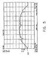
- a frequency spectrum 42includes not only the wideband signal from the mobile unit 13 having a frequency spectrum similar to the frequency spectrum 40 of FIG. 3, but includes three narrowband interferers 44, 46, 48, as shown in FIG. 4, one of which may be from the mobile unit 12. If a wideband signal having a frequency spectrum 42 including narrowband interferers 44, 46, 48 is received by the antenna 20 and amplified, split and presented to the ANF module 26, the ANF module 26 will filter the frequency spectrum 42 to produce a filtered frequency spectrum 50 as shown in FIG. 5.
- an ANF module 60scans the frequency spectrum of the signal provided by the splitter 24 and looks for narrowband interference therein. Such scanning may be implemented by scanning to various known narrowband channels that exist within the bandwidth of the wideband signal. For example, the ANF module 60 may scan to various AMPS channels that lie within the bandwidth of the wideband signal. Alternatively, all of the frequency spectrum encompassed by the wideband signal may be scanned. Either way, when narrowband interference is detected in the wideband signal, the ANF module 60 moves the narrowband interference into the notch of a notch filter, thereby filtering the wideband signal to remove the narrowband interference.
- the resulting filtered signalis coupled from the notch filter 66 to a second mixer 68, which is also driven by the VCO 64.
- the second mixer 68mixes the notch filter output with the signal from the VCO 64 to shift the frequency spectrum of the filtered signal back to an original position that the signal from the splitter 24 had.
- the output of the second mixer 68is coupled to a band pass filter 70, which removes any undesired image frequencies created by the second mixer 68.
- the output of the comparator 76is coupled to a sample and hold circuit 80, which receives input from a voltage sweep generator 82.
- the output of the voltage sweep generator 82passes through the sample and hold circuit 80 and is applied to a summer 84, which also receives input from a low pass filter 86 that is coupled to the output of the discriminator 74.
- the summer 84produces a signal that drives the VCO 64 in a closed loop manner. As the voltage sweep generator 82 sweeps its output voltage over time, the output of the summer 84 also sweeps, which causes the frequency output of the VCO 64 to sweep over time.
- the second embodiment of the ANF module 100may include a built in test equipment (BITE) module 114 and a bypass switch 116, which may be embodied in a model AS239-12 gallium arsenide single-pole, double-throw switch available from Hittite.
- BITEbuilt in test equipment
- the microcontroller 106 and the OA&M processor 108may be coupled to external memories 118 and 120, respectively.
- the scanner 102performs its function as follows.
- the signal from the splitter 24is coupled to the mixer 130, which receives an input from the programmable local oscillator 134.
- the mixer 130mixes the signals from the splitter 24 down to an IF, which is the frequency that the discriminator 132 analyses to produce an RSSI measurement that is coupled to the A/D 104.
- the A/D 104converts the RSSI signal from an analog signal into a digital signal that may be processed by the microcontroller 106.
- the microcontroller 106compares the output of the A/D 104 to an adaptive threshold that the microcontroller 106 has previously determined. Details regarding how the microcontroller 106 determines the adaptive threshold are provided hereinafter.
- the notch module 110includes a bypass switch 164 that may be used to bypass the notch module 110 in cases where there is no narrowband interference to be filtered or in the case of a notch module 110 failure.
- the microcontroller 106closes the bypass switch 164 when no interference is detected for which the notch module 110 is used to filter. Conversely, the microcontroller 106 opens the bypass switch 164 when interference is detected and the notch module 110 is to be used to filter such interference.
- a second embodiment of a notch filter block 166may include a switch 170 and multiple filters 172-178.
- each of the filters 172-178has a notch frequency tuned to the IF produced by the first mixer 150.
- each of the filters 172-178may have a different reject bandwidth at -40dB.
- the filters 172-178have reject bandwidths of 15 KHz to 120 KHz. The use of filters having various reject bandwidths enables the ANF module 100 to select a filter having an optimal reject bandwidth to best filter an interferer.
- the microcontroller 106controls the switch 170 to route the output signal from the first mixer 150 to one of the filters 172-178.
- the microcontroller 106via the switch 170, selects the filter 172-178 having a notch switch best suited to filter interference detected by the microcontroller 106. For example, if the microcontroller 106 determines that there is interference on a number of contiguous channels, the microcontroller 106 may use a filter 172-178 having a notch width wide enough to filter all such interference, as opposed to using a single filters to filter interference on each individual channel.
- a single filter having a wide bandwidthmay be used when two narrowband channels having interference are separated by a narrowband channel that does not have narrowband interference. Although the use of a single wide bandwidth filter will filter a narrowband channel not having interference thereon, the wideband signal information that is lost is negligible.
- the fail condition checkis used to ensure that the ANF module 100 is operating in a proper manner by checking for gross failures of the ANF module 100.
- the setup default values routine 202begins execution at a block 220 at which the microcontroller 106 tunes the programmable local oscillator 134 to scan for interference on a first channel designated as F1.
- F1maybe 836.52 megahertz (MHz).
- the first channel to which the ANF module 100 is tunedmay be any suitable frequency that lies within the frequency band or guard band of a wideband channel.
- the setup default values routine 202returns control to the main program and the block 204 is executed.
- the microcontroller 106reads interferer signal levels at the output of the notch module 112 via the A/D 104. Because the notch modules 110, 112 have been bypassed by the block 240, the signal levels at the output of the notch module 112 should include the interference that is produced by the BITE module 114.
- the signal processing and interference identification routine 206begins execution at a block 270.
- the microprocessor 106controls the programmable local oscillator 134 so that the microcontroller 106 can read signal strength values for each of the desired channels via the discriminator 132 and the A/D 104.
- the microcontroller 106may control the programmable local oscillator 134 to tune sequentially to a number of known channels. The tuning moves each of the known channels to the IF so that the discriminator 132 can make an RSSI reading of the signal strength of each channel.
- the channels having the higher probabilitymay be scanned first. Channels may be determined to have a higher probability of having interference based on historical interference patters or interference data observed by the ANF module 100.
- the guard band compensationhas a frequency response that is the same as the frequency response of the wideband receiver filter. For example, if a wideband receiver filter would attenuate a particular frequency by 10dB, the readings of guard bands at that particular frequency would be attenuated by 10dB.
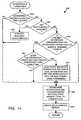
- the interference extraction routine 208begins execution at a block 290, which compares the time duration that an interferer has been present with a reference time called “duration time allowed,” which may also be referred to as "attack time.” If the interferer has been present longer than the attack time, control passes to a block 292. Alternatively, if the interferer has not been present longer than the duration time allowed, control passes to a block 296, which is described in further detail below.
- the block 290acts as a hysteresis function that prevents filters from being assigned to temporary interferers immediately as such interferers appear.
- the duration time allowedmay be on the order of 20 milliseconds (ms), which is approximately the frame rate of a CDMA communication system.
- the microcontroller 106rearranges interferers from lowest level to highest level and assigns notches to the highest level interferers.
- the block 296performs prioritizing functions to ensure that the strongest interferers are filtered with notch modules. Additionally, the block 296 may analyze the interference pattern detected by the ANF module 100 and may assign filters 172-178 having various notch widths to filter interferers. For example, if the ANF module 100 detects interference on contiguous channels collectively have a bandwidth of 50 KHz, the 50 KHz filter 176 of the notch filter block 158 may be used to filter such interference, rather than using four 15 KHz filters. Such a technique essentially frees up notch filter modules 110, 112 to filter additional interferers.
- the microcontroller 106determines if a gross failure has occurred in the ANF module 100. Such a determination may be made by, for example, determining if a voltage output from a voltage regulator of the ANF module 100 has an appropriate output voltage. Alternatively, gross failures could be determined by testing to see if each of the notch modules 110, 112 are inoperable. If each of the notch modules is inoperable, it is likely that a gross failure of the ANF module 100 has occurred. Either way, if a gross failure has occurred, control passes from the block 320 to a block 322 at which point the microcontroller 106 enables the bypass switch 116 of FIG.
- the OA&M processor 108stores the interferer start time and duration. Such information may be stored within the OA&M processor 108 itself or may be stored within the external memory 120 of the OA&M processor 108.
- controlpasses to the block 352.
- the duration of the interfereris incremented to represent the time that the interferer has been present. After the execution of block 372, control passes to the block 352.
- the block 394will determine that the bypass time does exceed the hold time and pass control to the block 396.
- the main routine 340ends.
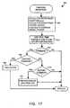
- the interference reportsmay be used by a network administrator to correlate system performance with the information provided in the interference report. Such correlations could be used to determine the effectiveness of the ANF module 100 on increasing system capacity.
Landscapes
- Engineering & Computer Science (AREA)
- Computer Networks & Wireless Communication (AREA)
- Signal Processing (AREA)
- Quality & Reliability (AREA)
- Noise Elimination (AREA)
- Mobile Radio Communication Systems (AREA)
Description
- This application claims the benefit of U.S. Provisional Application No. 60/195,387 filed on April 7, 2000.
- The present invention is directed to communication systems and, more particularly, to a technique for detecting, identifying, extracting and eliminating narrowband interference in a wideband communication system.
- As shown in FIG. 1, an
exemplary telecommunication system 10 may includemobile units reference numerals base stations base stations - During operation, the
mobile units base stations mobile unit 12 to one of thebase stations mobile unit 12 with a land line telephone so that the land line telephone may receive the voice information. Conversely, information, such as voice information may be transferred from a land line telephone to one of thebase stations mobile unit 12. - The
mobile units base stations mobile unit 12 is a narrowband analog unit and that themobile unit 13 is a wideband digital unit. Additionally, it is assumed that thebase station 14 is a narrowband analog base station that communicates with themobile unit 12 and that thebase station 16 is a wideband digital base station that communicates with themobile unit 13. - Analog format communication takes
place using narrowband 30 kilohertz (KHz) channels. The advanced mobile phone systems (AMPS) is one example of an analog communication system in which themobile unit 12 communicates with thebase station 14 using narrowband channels. Alternatively, themobile unit 13 communicates with thebase stations 16 using a form of digital communications such as, for example, code-division multiple access (CDMA) or time-division multiple access (TDMA). Digital communication takes place using spread spectrum techniques that broadcast signals having wide bandwidths, such as, for example, 1.25 megahertz (MHz) bandwidths. - The switching station 18 is generally responsible for coordinating the activities of the
base stations mobile units base station mobile unit 12 between thebase stations 14 and another analog base station as themobile unit 12 roams between geographical areas that are covered by the two base stations. - One particular problem that may arise in the
telecommunication system 10 is when themobile unit 12 or thebase station 14, each of which communicate using narrowband channels, interfere with the ability of thebase station 16 to receive and process wideband digital signals from the digitalmobile unit 13. In such a situation, the narrowband signal transmitted from themobile unit 12 or thebase station 14 may interfere with the ability of thebase station 16 to properly receive wideband communication signals. - European Patent Application No: 0704986 discloses a CDMA receiver for receiving spread spectrum modulated signals. The receiver comprises a processor that analyses each of the carrier signals of a multi carrier signal to determine the relative power of each of the constituent carrier signals and amplifies any carrier signal having a power below a threshold lower limit and attenuates any carrier signal having a power above a threshold upper limit.
- According to one aspect, the present invention may be embodied in a method of detecting and eliminating narrowband interference in a wideband communication signal having a frequency bandwidth with narrowband channels disposed therein, wherein guard bands having guard band frequencies are adjacent the frequency bandwidth, the method characterised by scanning at least some of the narrowband channels to determine signal strengths in at least some of the narrowband channels and determining the threshold based on the signal strengths in at least some of the narrowband channels, scanning the guard band frequencies to determine guard band signal strengths and filtering a guard band frequency when the guard band signal strength exceeds the threshold.
- According to a second aspect, the present invention may be embodied in a system adapted to detect and eliminate narrowband interference in a wideband communication signal having a frequency bandwidth with narrowband channels disposed therein, wherein guard bands having guard band frequencies are adjacent the frequency bandwidth the system comprising a scanner adapted to scan at least some of the narrowband channels to determine signal strengths in at least some of the narrowband channels, a notch module adapted to receive the wideband communication signal and to selectively remove narrowband interference from the wideband communication signal to produce a filtered wideband communication signal and a controller coupled to the scanner and to the notch module, wherein the controller is adapted to control the scanner to scan at least some of the narrowband channels, to determine signal strengths in at least some of the narrowband channels, characterised in that the controller is further adapted to determine a threshold based on the signal strengths in at least some of the narrowband channels, to control the scanner to scan the guard band frequencies to determine guard band signal strengths and to control the notch module to selectively filter a guard band frequency when the guard band signal strength exceeds the threshold.
- The method may include scanning at least some of the narrowband channels to determine signal strengths in at least some of the narrowband channels, determining a threshold based on the signal strengths in at least some of the narrowband channels and identifying narrowband channels having signal strengths exceeding the threshold. The method may also include identifying narrowband channels having temporary interference and filtering the wideband communication signal at a frequency corresponding to a narrowband channel having a signal strength exceeding the threshold, but not filtering the narrowband channels identified as having temporary interference.
- Such a system may include a scanner adapted to scan at least some of the narrowband channels to determine signal strengths in at least some of the narrowband channels and a notch module adapted to receive the wideband communication signal and to selectively remove narrowband interference from the wideband communication signal to produce a filtered wideband communication signal. The system may also include a controller coupled to the scanner and to the notch module, wherein the controller is adapted to operate in conjunction with the scanner to determine a threshold based on the signal strengths in at least some of the narrowband channels. The controller may also be adapted to identify narrowband channels having signal strengths exceeding the threshold and to identify narrowband channels having a temporary interference. Further, the controller may be adapted to control the notch module to filter the wideband communication signal at a frequency corresponding to an identified narrowband channel having a signal strength exceeding the threshold, but not to filter the narrowband channels having temporary interference.
- Such a method may include scanning at least some of the narrowband channels to determine signal strengths in at least some of the narrowband channels in an order representative of a probability that the narrowband channels will have interference and determining a threshold based on the signal strengths in at least some of the narrowband channels. Additionally, the method may include identifying narrowband channels having signal strengths exceeding the threshold and filtering the wideband communication signal at a frequency corresponding to an identified narrowband channel having signal strengths exceeding the threshold.
- The system may include a scanner adapted to scan at least some of the narrowband channels to determine signal strengths in at least some of the narrowband channels in an order representative of a probability that the narrowband channels will have interference and a notch module adapted to receive the wideband communication signal and to selectively remove narrowband interference from the wideband communication signal to produce a filtered wideband communication signal. The system may also include a controller coupled to the scanner and to the notch module, wherein the controller is adapted to operate in conjunction with the scanner to determine a threshold based on the signal strengths in at least some of the narrowband channels, to identify narrowband channels having signal strengths exceeding the threshold and to control the notch module to filter the wideband communication signal at a frequency corresponding to an identified narrowband channel having a signal strength exceeding the threshold.
- Such a method may include scanning at least some of the narrowband channels to determine signal strengths in at least some of the narrowband channels, determining a threshold based on the signal strengths in at least some of the narrowband channels and storing a list of narrowband channels having signal strengths that exceed the threshold. The method may also include identifying a type of interference source based on the list of narrowband channels having signal strengths that exceed the threshold and filtering the wideband communication signal at a frequency corresponding to an identified narrowband channel having a signal strength exceeding the threshold, wherein the filtering is based on the type of interference source identified.
- Such system may include a scanner adapted to scan at least some of the narrowband channels to determine signal strengths in at least some of the narrowband channels in an order representative of a probability that the narrowband channels will have interference and a notch module adapted to receive the wideband communication signal and to selectively remove narrowband interference from the wideband communication signal to produce a filtered wideband communication signal. Additionally, such a system may include a controller coupled to the scanner and to the notch module, wherein the controller is adapted to store a list of narrowband channels having signal strengths that exceed the threshold, to identify a type of interference source based on the list of narrowband channels having signal strengths that exceed the threshold and to control the notch module to filter the wideband communication signal at a frequency corresponding to an identified narrowband channel having a signal strength exceeding the threshold, wherein the filter used by the notch module is based on the type of interference source identified.
- The method may include scanning at least some of the narrowband channels to determine signal strengths in at least some of the narrowband channels, determining a threshold based on the signal strengths in at least some of the narrowband channels and storing a list of narrowband channels having signal strengths that exceed the threshold. The method may also include assigning filters to at least some of the identified narrowband channels having signal strengths exceeding the threshold and outputting to a network administrator the list of narrowband channels having signal strengths that exceed the threshold.
- These and other features of the present invention will be apparent to those of ordinary skill in the art in view of the description of the preferred embodiments, which is made with reference to the drawings, a brief description of which is provided below.
- FIG.1 is an exemplary illustration of a communication system;
- FIG. 2 is an exemplary illustration of a base station of FIG. 1;
- FIG. 3 is an exemplary illustration of a frequency spectrum of a wideband signal in the absence of interference;
- FIG. 4 is an exemplary illustration of a frequency spectrum of a wideband signal in the presence of three narrowband interferers;
- FIG. 5 is an exemplary illustration of a frequency spectrum of a wideband signal having three narrowband interferers removed therefrom;
- FIG. 6 is an exemplary illustration of one embodiment of an adaptive notch filter (ANF) module of FIG. 2;
- FIG. 7 is an exemplary illustration of a second embodiment of an ANF module of FIG. 2;
- FIG. 8 is an exemplary illustration of a notch module of FIG. 7;
- FIG. 9 is an exemplary illustration of a second embodiment of a notch filter block of FIG. 8;
- FIG. 10 is an exemplary flow diagram of a main routine executed by the microcontroller of FIG. 7;
- FIG. 11 is an exemplary flow diagram of a setup default values routine executed by the microcontroller of FIG. 7;
- FIG. 12 is an exemplary flow diagram of a built in test equipment (BITE) test routine executed by the microcontroller of FIG. 7;
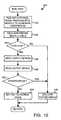
- FIG. 13 is an exemplary flow diagram of a signal processing and interference identification routine executed by the microcontroller of FIG. 7;
- FIG. 14 is an exemplary flow diagram of an interference extraction routine executed by the microcontroller of FIG. 7;
- FIG. 15 is an exemplary flow diagram of a fail condition check routine executed by the microcontroller of FIG. 7;
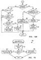
- FIGS. 16A and 16B form an exemplary flow diagram of a main routine executed by the operations, alarms and metrics (OA&M) processor of FIG. 7;
- FIG. 17 is an exemplary flow diagram of a prepare response routine executed by the OA&M processor of FIG. 7; and
- FIG. 18 is an exemplary flow diagram of a data buffer interrupt function executed by the OA&M processor of FIG. 7.
- As disclosed in detail hereinafter, a system and/or a method for detecting, identifying, extracting and reporting interference may be used in a communication system. In particular, such a system or method may be employed in a wideband communication system to protect against, or to report the presence of, narrowband interference, which has deleterious effects on the performance of the wideband communication system.
- As shown in FIG. 2, the signal reception path of the
base station 16, which was described as receiving narrowband interference from themobile unit 12 in conjunction with FIG. 1, includes anantenna 20 that provides signals to a low noise amplifier (LNA) 22. The output of theLNA 22 is coupled to asplitter 24 that splits the signal from the LNA into a number of different paths, one of which may be coupled to an adaptive notch filter (ANF)module 26 and another of which may be coupled to anarrowband receiver 28. The output of theANF module 26 is coupled to awideband receiver 30, which may, for example, be embodied in a CDMA receiver or any other suitable wideband receiver. Thenarrowband receiver 28 may be embodied in a 15 KHz bandwidth receiver or in any other suitable narrowband receiver. Although only one signal path is shown in FIG. 2, it will be readily understood to those having ordinary skill in the art that such a signal path is merely exemplary and that, in reality, a base station may include two or more such signal paths that may be used to process main and diversity signals received by thebase station 16. - The outputs of the
narrowband receiver 28 and thewideband receiver 30 are coupled to other systems within thebase station 16. Such systems may perform voice and/or data processing, call processing or any other desired function. Additionally, theANF module 26 is also communicatively coupled, via the Internet, telephone lines or any other suitable media, to a reporting and control facility that is remote from thebase station 16. In some networks, the reporting and control facility may be integrated with the switching station 18. Thenarrowband receiver 28 is communicatively coupled to the switching station 18 and may respond to commands that the switching station 18 issues. - Each of the components 20-30 of the
base station 16 shown in FIG. 2, except for theANF module 26, may be found in a conventional wideband cellular base station, the details of which are well known to those having ordinary skill in the art. It will also be appreciated by those having ordinary skill in the art that FIG. 2 does not disclose every system or subsystem of thebase station 16 and, rather, focuses on the systems and subsystems of thebase station 16 that are relevant to the description of the present invention. In particular, it will be readily appreciated that, while not shown in FIG. 2, thebase station 16 includes a transmission system or subsystem. - During operation of the
base station 16, theantenna 20 receives wideband signals that are broadcast from themobile unit 13 and couples such signals to theLNA 22, which amplifies the received signals and couples the amplified signals to thesplitter 24. Thesplitter 24 splits the amplified signal from theLNA 22 and essentially puts copies of the amplified signal on each of its output lines. TheANF module 26 receives the signal from thesplitter 24 and, if necessary, filters the wideband signal to remove any undesired narrowband interference and couples the filtered wideband signal to thewideband receiver 30. - FIG. 3 illustrates a
frequency spectrum 40 of a wideband signal that may be received at theantenna 20, amplified and split by theLNA 22 and thesplitter 24 and coupled to theANF module 26. If the wideband signal received at theantenna 20 has afrequency spectrum 40 as shown in FIG. 3, theANF module 26 will not filter the wideband signal and will simply couple the wideband signal directly through theANF module 26 to thewideband receiver 30. - However, as noted previously, it is possible that the wideband signal transmitted by the
mobile unit 13 and received by theantenna 20 has afrequency spectrum 42 as shown in FIG. 4. Such afrequency spectrum 42 includes not only the wideband signal from themobile unit 13 having a frequency spectrum similar to thefrequency spectrum 40 of FIG. 3, but includes threenarrowband interferers mobile unit 12. If a wideband signal having afrequency spectrum 42 includingnarrowband interferers antenna 20 and amplified, split and presented to theANF module 26, theANF module 26 will filter thefrequency spectrum 42 to produce a filteredfrequency spectrum 50 as shown in FIG. 5. - The filtered
frequency spectrum 50 has thenarrowband interferers frequency spectrum 50 that is very similar to thefrequency spectrum 40, which does not include any interference. The filtered wideband signal is then coupled from theANF module 26 to thewideband receiver 30, so that the filteredwideband signal spectrum 50 may be demodulated. Although some of the wideband signal was removed during filtering by theANF module 26, sufficient wideband signal remains to enable thewideband receiver 30 to recover the information that was broadcast by a mobile unit. Accordingly, in general terms, theANF module 26 selectively filters wideband signals to remove narrowband interference therefrom. Further detail regarding theANF module 26 and its operation is provided below in conjunction with FIGS. 6-17. - In general, one embodiment of an
ANF module 60, as shown in FIG. 6, scans the frequency spectrum of the signal provided by thesplitter 24 and looks for narrowband interference therein. Such scanning may be implemented by scanning to various known narrowband channels that exist within the bandwidth of the wideband signal. For example, theANF module 60 may scan to various AMPS channels that lie within the bandwidth of the wideband signal. Alternatively, all of the frequency spectrum encompassed by the wideband signal may be scanned. Either way, when narrowband interference is detected in the wideband signal, theANF module 60 moves the narrowband interference into the notch of a notch filter, thereby filtering the wideband signal to remove the narrowband interference. - In particular, as shown in FIG. 6, the signal from the
splitter 24 is coupled to afirst mixer 62, which receives an additional input from a voltage controlled oscillator (VCO) 64. Thefirst mixer 62 mixes the signal from thesplitter 26 with the signal from theVCO 64, thereby shifting the frequency spectrum of the signal from thesplitter 24 and putting a portion of the shifted frequency spectrum located at intermediate frequency (IF) into a notch frequency of anotch filter 66. Accordingly, the component of the frequency shifted signal that is at the IF is removed by thenotch filter 66 having a notch frequency set at the IF. - The resulting filtered signal is coupled from the
notch filter 66 to asecond mixer 68, which is also driven by theVCO 64. Thesecond mixer 68 mixes the notch filter output with the signal from theVCO 64 to shift the frequency spectrum of the filtered signal back to an original position that the signal from thesplitter 24 had. The output of thesecond mixer 68 is coupled to aband pass filter 70, which removes any undesired image frequencies created by thesecond mixer 68. - In the system of FIG. 6, the narrowband interference present in the wideband signal is mixed to the IF, which is the notch frequency of the
notch filter 66, by thefirst mixer 62 and is, therefore, removed by thenotch filter 66. After the narrowband interference has been removed by thenotch filter 66, thesecond mixer 68 restores the signal to its original frequency position, except that the narrowband interference has been removed. Collectively, thefirst mixer 62, theVCO 64, thenotch filter 66, thesecond mixer 68 and the band pass filter may be referred to as an "up, down filter" or a "down, up filter." - The signal from the
splitter 24 is also coupled to abypass switch 72 so that if no narrowband interference is detected in the wideband signal from thesplitter 24, thebypass switch 72 may be enabled to bypass thenotch filter 66 and themixers splitter 24 directly to thewideband receiver 30. Alternatively, if narrowband interference is detected, thebypass switch 72 is opened and the signal from thesplitter 24 is forced to go through thenotch filter 66. - To detect the presence of narrowband interference and to effectuate frequency scanning, a number of components are provided. A
discriminator 74 receives the output signal from thefirst mixer 62 and detects signal strength at the IF using a received signal strength indicator (RSSI) that is tuned to the IF. The RSSI output of thediscriminator 74 is coupled to acomparator 76, which also receives a threshold voltage on aline 78. When the RSSI signal from thediscriminator 74 exceeds the threshold voltage on theline 78, thecomparator 76 indicates that narrowband interference is present at the IF, which is the notch frequency of thenotch filter 66. When narrowband interference is detected, the sweeping action of theVCO 64 is stopped so that thenotch filter 66 can remove the interference at the IF. - To affect the sweeping action of the
VCO 64, the output of thecomparator 76 is coupled to a sample and holdcircuit 80, which receives input from avoltage sweep generator 82. Generally, when no interference is detected by thecomparator 76, the output of thevoltage sweep generator 82 passes through the sample and holdcircuit 80 and is applied to asummer 84, which also receives input from alow pass filter 86 that is coupled to the output of thediscriminator 74. Thesummer 84 produces a signal that drives theVCO 64 in a closed loop manner. As thevoltage sweep generator 82 sweeps its output voltage over time, the output of thesummer 84 also sweeps, which causes the frequency output of theVCO 64 to sweep over time. The sweeping output ofVCO 64, in conjunction with thediscriminator 74 and thecomparator 76, scan the signal from thesplitter 24 for interference. As long as thecomparator 76 indicates that narrowband interference is not present, theswitch 72 is held closed, because there is no need to filter the signal from thesplitter 24. - However, when the
comparator 76 detects narrowband interference in the signal from the splitter 24 (i.e., when the RSSI exceeds the voltage on the line 78), the sample and holdcircuit 80 samples the output of thevoltage sweep generator 82 and holds the sampled voltage level, thereby providing a fixed voltage to thesummer 84, which, in turn, provides a fixed output voltage to theVCO 64. Because a fixed voltage is provided to theVCO 64, the frequency output by theVCO 64 does not change and the signal from thesplitter 24 is no longer scanned, but is frequency shifted so that the narrowband interference is moved to the IF, which is the notch frequency of thenotch filter 66. Additionally, when thecomparator 76 indicates that narrowband interference is present, theswitch 72 opens and the only path for the signal from thesplitter 24 to take is the path through themixers notch filter 66. - The threshold voltage on the
line 78 may be hand tuned or may be generated by filtering some received signal strength. Either way, the voltage on theline 78 should be set so that thecomparator 76 does not indicate that interference is present when only a wideband signal, such as the signal shown in FIG. 3, is present, but only indicates interference when a signal having narrowband interference is present. For example, thefrequency spectrum 42 shown in FIG. 4, shows threenarrowband interferers comparator 76 to indicate the presence of narrowband interference. As will be readily appreciated, the embodiment shown in FIG. 6 is only able to select and filter a single narrowband interferer within a wideband signal. - As shown in FIG. 7, a second embodiment of an
ANF module 100, which may filter a number of narrowband interferers, generally includes ascanner 102, an analog to digital converter (A/D) 104, amicrocontroller 106, an operations, alarms and metrics (OA&M)processor 108 and notch modules, two of which are shown in FIG. 7 atreference numerals microcontroller 106 and theOA&M processor 108 may be embodied in a model PIC16C77-20P microcontroller, which is manufactured by Microchip Technology, Inc., and a model 80386 processor, which is manufactured by Intel Corp., respectively. Although they are shown and described herein as separate devices that execute separate software instructions, those having ordinary skill in the art will readily appreciate that the functionality of themicrocontroller 106 and theOA&M processor 108 may be merged into a single processing device. - Additionally, the second embodiment of the
ANF module 100 may include a built in test equipment (BITE)module 114 and abypass switch 116, which may be embodied in a model AS239-12 gallium arsenide single-pole, double-throw switch available from Hittite. Themicrocontroller 106 and theOA&M processor 108 may be coupled toexternal memories - In general, the
scanner 102, which includes amixer 130, adiscriminator 132 and a programmablelocal oscillator 134, interacts with the A/D 104 and themicrocontroller 106 to detect the presence of narrowband interference in the signal provided by thesplitter 24. Themixer 130 and the programmablelocal oscillator 134 may be embodied in a model MD-54-0005 mixer available from MIA-Com and a model AD9831 direct digital synthesizer, which is manufactured by Analog Devices, Inc., respectively. Additionally, the A/D 104 may be completely integrated within themicrocontroller 106 or may be a stand alone device coupled thereto. - As described in further detail below, once narrowband interference is detected in the signal from the
splitter 24, themicrocontroller 106, viaserial bus 136, controls thenotch modules ANF module 100, as shown in FIG. 7, includes twonotch modules ANF module 100. The number of notch modules that may be used in theANF module 100 is only limited by the signal degradation that each notch module contributes. Because multiple notch modules are provided, multiple narrowband interferers may be removed from the wideband signal from thesplitter 24. For example, if three notch modules were provided, a wideband signal having thefrequency spectrum 42, as shown in FIG. 4, may be processes by theANF module 110 to produce a filtered wideband signal having thefrequency spectrum 50, as shown in FIG. 5. - The
scanner 102 performs its function as follows. The signal from thesplitter 24 is coupled to themixer 130, which receives an input from the programmablelocal oscillator 134. Themixer 130 mixes the signals from thesplitter 24 down to an IF, which is the frequency that thediscriminator 132 analyses to produce an RSSI measurement that is coupled to the A/D 104. The A/D 104 converts the RSSI signal from an analog signal into a digital signal that may be processed by themicrocontroller 106. Themicrocontroller 106 compares the output of the A/D 104 to an adaptive threshold that themicrocontroller 106 has previously determined. Details regarding how themicrocontroller 106 determines the adaptive threshold are provided hereinafter. If themicrocontroller 106 determines that the output from the A/D 104, which represents RSSI, exceeds the adaptive threshold, one of thenotch modules splitter 24 at the IF having an RSSI that exceeds the adaptive threshold. - The
microcontroller 106 also programs the programmablelocal oscillator 134 so that themixer 130 moves various portions of the frequency spectrum of the signal from thesplitter 24 to the IF that thediscriminator 132 processes. For example, if there are 59 narrowband channels that lie within the frequency band of a particular wideband channel, themicrocontroller 106 will sequentially program the programmablelocal oscillator 134 so that each of the 59 channels is sequentially mixed down to the IF by themixer 132 so that thediscriminator 132 can produce RSSI measurements for each channel. Accordingly, themicrocontroller 106 uses the programmablelocal oscillator 134, themixer 130 and thediscriminator 132 to analyze the signal strengths in each of the 60 narrowband channels lying within the frequency band of the wideband signal. By analyzing each of the channels that lie within the frequency band of the wideband signal, themicrocontroller 106 can determine an adaptive threshold and can determine whether narrowband interference is present in one or more of the narrowband channels. - Once channels having narrowband interference are identified, the
microcontroller 106 may program thenotch modules microcontroller 106 may also store lists of channels having interferers, as well as various other parameters. Such a list may be transferred to the reporting and control facility or a base station, via theOA&M processor 108, and may be used for system diagnostic purposes. - Diagnostic purposes may include, but are not limited to, controlling the
narrowband receiver 28 to obtain particular information relating to an interferer and retasking the interferer by communicating with its base station. For example, the reporting and control facility may use thenarrowband receiver 28 to determine the identity of an interferer, such as a mobile unit, by intercepting the electronic serial number (ESN) of the mobile unit, which is sent when the mobile unit transmits information on the narrowband channel. Knowing the identity of the interferer, the reporting and control facility may contact infrastructure that is communicating with the mobile unit and may request the infrastructure to change the transmit frequency of the mobile unit (i.e., the frequency of the narrowband channel on which the mobile unit is transmitting) or may request the infrastructure to drop communications with the interfering mobile unit all together. - Additionally, diagnostic purposes may include using the
narrowband receiver 28 to determine a telephone number that the mobile unit is attempting to contact and, optionally handling the call. For example, the reporting and control facility may use thenarrowband receiver 28 to determine that the user of the mobile unit was dialing 911, or any other emergency number, and may, therefore, decide that thenarrowband receiver 28 should be used to handle the emergency call by routing the output of thenarrowband receiver 28 to a telephone network. - FIG. 8 reveals further detail of one of the
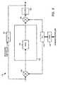
notch modules 110, it being understood that any other notch modules used in theANF module 100 may be substantially identical to thenotch module 110. In general, thenotch module 110 is an up, down or down, up filter having operational principles similar to theANF module 60 described in conjunction with FIG. 6. In particular, thenotch module 110 includes first andsecond mixers logic block 156 to theserial bus 136 of themicrocontroller 106. Disposed between themixers notch filter block 158, further detail of which is described below. In practice, themixers PLL 154 may be embodied in a model LMX2316TM frequency synthesizer that is commercially available from National Semiconductor. - During operation of the
ANF module 100, themicrocontroller 106 controls thePLL 154 to produce an output signal that causes thefirst mixer 150 to shift the frequency spectrum of the signal from thesplitter 24 to an IF, which is the notch frequency of thenotch filter block 158. Alternatively, in the case of cascaded notch modules, the notch module may receive its input from another notch module and not from thesplitter 24. The output of thePLL 154 is also coupled to the second mixer to shift the frequency spectrum of the signal from thenotch filter block 158 back to its original position as it was received from thesplitter 24 after thenotch filter block 158 has removed narrowband interference therefrom. The output of thesecond mixer 152 is further coupled to afilter 160 to remove any undesired image frequencies that may be produced by thesecond mixer 152. The output of thefilter 160 may be coupled to an additional notch module (e.g., the notch module 112) or, if no additional notch modules are used, may be coupled directly to thewideband receiver 30. - Additionally, the
notch module 110 includes abypass switch 164 that may be used to bypass thenotch module 110 in cases where there is no narrowband interference to be filtered or in the case of anotch module 110 failure. For example, themicrocontroller 106 closes thebypass switch 164 when no interference is detected for which thenotch module 110 is used to filter. Conversely, themicrocontroller 106 opens thebypass switch 164 when interference is detected and thenotch module 110 is to be used to filter such interference. - As shown in FIG. 8, the
notch filter block 158 includes afilter 165, which may be, for example a filter having a reject band that is approximately 15 KHz wide at -40dB. The reject band of thefilter 165 may be fixed at, for example, a center frequency of 150 MHz or at any other suitable frequency at which the IF of themixer 150 is located. - Although the notch filter block 158 of FIG. 8 shows only a
single filter 165, as shown in FIG. 9, a second embodiment of anotch filter block 166 may include aswitch 170 and multiple filters 172-178. In such an arrangement, each of the filters 172-178 has a notch frequency tuned to the IF produced by thefirst mixer 150. Additionally, each of the filters 172-178 may have a different reject bandwidth at -40dB. For example, as shown in FIG. 9, the filters 172-178 have reject bandwidths of 15 KHz to 120 KHz. The use of filters having various reject bandwidths enables theANF module 100 to select a filter having an optimal reject bandwidth to best filter an interferer. - During operation, of the second embodiment of the
notch filter block 166, themicrocontroller 106 controls theswitch 170 to route the output signal from thefirst mixer 150 to one of the filters 172-178. Themicrocontroller 106, via theswitch 170, selects the filter 172-178 having a notch switch best suited to filter interference detected by themicrocontroller 106. For example, if themicrocontroller 106 determines that there is interference on a number of contiguous channels, themicrocontroller 106 may use a filter 172-178 having a notch width wide enough to filter all such interference, as opposed to using a single filters to filter interference on each individual channel. Additionally, a single filter having a wide bandwidth may be used when two narrowband channels having interference are separated by a narrowband channel that does not have narrowband interference. Although the use of a single wide bandwidth filter will filter a narrowband channel not having interference thereon, the wideband signal information that is lost is negligible. - Having described the detail of the hardware aspects of the system, attention is now turned to the software aspects of the system. Of course, it will be readily understood by those having ordinary skill in the art that software functions may be readily fashioned into hardware devices such as, for example, application specific integrated circuits (ASICs). Accordingly, while the following description pertains to software, such a description is merely exemplary and should not be considered limiting in any way.
- That being said, FIGS. 10-15 include a number of blocks representative of software or hardware functions or routines. If such blocks represent software functions, instructions embodying the functions may be written as routines in a high level language such as, for example, C, or any other suitable high level language, and may be compiled into a machine readable format. Alternatively, instructions representative of the blocks may be written in assembly code or in any other suitable language. Such instructions may be stored within the
microcontroller 106 or may be stored within theexternal memory 118 and may be recalled therefrom for execution by themicrocontroller 106. - A
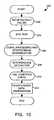
main routine 200, as shown in FIG. 10, includes a number of blocks or routines that are described at a high level in connection with FIG. 10 and are described in detail with respect to FIGS. 11-15. Themain routine 200 begins execution at ablock 202 at which themicrocontroller 102 sets up default values and prepares to carry out the functionality of theANF module 100. After the setup default values function is complete, control passes to ablock 204, which performs a built-in test equipment (BITE) test of theANF module 100. - After the BITE test has been completed, control passes from the
block 204 to ablock 206, which performs signal processing and interference identification. After the interference has been identified at theblock 206, control passes to ablock 208 where the identified interference is extracted from the wideband signal received by theANF module 100. - After the interference has been extracted at the
block 208, control passes to ablock 210 at which a fail condition check is carried out. The fail condition check is used to ensure that theANF module 100 is operating in a proper manner by checking for gross failures of theANF module 100. - After the fail condition check completes, control passes from the
block 210 to ablock 212, which performs interference data preparation that consists of passing information produced by some of the blocks 202-210 from themicrocontroller 106 to theOA&M 108. Upon completion of the interference data preparation, the main routine 200 ends its execution. The main routine 200 may be executed by themicrocontroller 106 at time intervals such as, for example, every 20 ms. - As shown in FIG. 11, the setup default values routine 202 begins execution at a
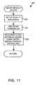
block 220 at which themicrocontroller 106 tunes the programmablelocal oscillator 134 to scan for interference on a first channel designated as F1. For example, as shown in FIG. 11, F1 maybe 836.52 megahertz (MHz). Alternatively, as will be readily appreciated by those having ordinary skill in the art, the first channel to which theANF module 100 is tuned may be any suitable frequency that lies within the frequency band or guard band of a wideband channel. - After the
microcontroller 106 is set up to scan for interference on a first frequency, control passes from theblock 220 to ablock 222, which sets up default signal to noise thresholds that are used to determine the presence of narrowband interference in wideband signals received from thesplitter 24 of FIG. 2. Although subsequent description will provide detail on how adaptive thresholds are generated, theblock 222 merely sets up an initial threshold for determining presence of narrowband interference. - After the default thresholds have been set at the
block 222 control passes to ablock 224 at which themicrocontroller 106 reads various inputs, establishes serial communication with thenotch modules OA&M processor 108. After theblock 224 completes execution, the setup default values routine 202 returns control to the main program and theblock 204 is executed. - FIG. 12 reveals further detail of the
BITE test routine 204, which begins execution after the routine 202 completes. In particular, theBITE test routine 204 begins execution at ablock 240, at which themicrocontroller 106 puts thenotch modules notch modules microcontroller 106 programs theBITE module 114 to generate interferers that will be used to test the effectiveness of thenotch modules notch modules BITE module 114 is enabled, control passes from theblock 240 to ablock 242. - At the
block 242, themicrocontroller 106 reads interferer signal levels at the output of thenotch module 112 via the A/D 104. Because thenotch modules block 240, the signal levels at the output of thenotch module 112 should include the interference that is produced by theBITE module 114. - After the interferer signal levels have been read at the
block 242, ablock 244 determines whether the read interferer levels are appropriate. Because thenotch modules block 240, themicrocontroller 106 expects to see interferers at the output of thenotch module 112. If the levels of the interferer detected at the output of thenotch module 112 are not acceptable (i.e., are too high or too low), control passes from theblock 244 to ablock 246 where a system error is declared. Declaration of a system error may include themicrocontroller 106 informing theOA&M processor 108 of the system error. TheOA&M processor 108, in turn, may report the system error to a reporting and control facility. Additionally, declaration of a system error may include writing the fact that a system error occurred into theexternal memory 118 of themicrocontroller 106. - Alternatively, if the
block 244 determines that the interferer levels are appropriate, control passes from theblock 244 to ablock 248 at which themicrocontroller 106 applies one or more of the notch modules, 110, 112. After thenotch modules block 248, control passes to ablock 250, which reads the signal level at the output of thenotch module 112. Because theBITE module 114 produces interference at frequencies to which the notch filters are applied by theblock 248, it is expected that thenotch modules - After the signal levels are read by the
block 250, control passes to ablock 252, which determines if interference is present. If interference is present, control passes from theblock 252 to theblock 246 and a system error is declared because one or more of thenotch modules notch modules BITE module 114. Alternatively, if no interference is detected at theblock 252, theANF module 100 is functioning properly and is, therefore, set to a normal mode of operation at ablock 254. After theblock 254 or theblock 246 have been executed, the BITE test routine 204 returns control to themain program 200, which begins executing theblock 206. - As shown in FIG. 13, the signal processing and
interference identification routine 206 begins execution at ablock 270. At theblock 270, themicroprocessor 106 controls the programmablelocal oscillator 134 so that themicrocontroller 106 can read signal strength values for each of the desired channels via thediscriminator 132 and the A/D 104. In particular, themicrocontroller 106 may control the programmablelocal oscillator 134 to tune sequentially to a number of known channels. The tuning moves each of the known channels to the IF so that thediscriminator 132 can make an RSSI reading of the signal strength of each channel. Optionally, if certain channels have a higher probability of having interference than other channels, the channels having the higher probability may be scanned first. Channels may be determined to have a higher probability of having interference based on historical interference patters or interference data observed by theANF module 100. - Additionally, at the
block 270, themicrocontroller 106 controls the programmablelocal oscillator 134 to frequency shift portions of the guard bands to the IF so that thediscriminator 132 can produce RSSI measurements of the guard bands. Because the guard bands are outside of a frequency response of a filter disposed within thewideband receiver 30, theblock 270 compensates guard band signal strength reading by reducing the values of such readings by the amount that the guard bands will be attenuated by a receiver filter within thewideband receiver 30. Compensation is carried out because theANF module 100 is concerned with the deleterious effect of narrowband signals on thewideband receiver 30. Accordingly, signals having frequencies that lie within the passband of the filter of thewideband receiver 30 do not need to be compensated and signals falling within the guard band that will be filtered by the receive filter of thewideband receiver 30 need to be compensated. Essentially, the guard band compensation has a frequency response that is the same as the frequency response of the wideband receiver filter. For example, if a wideband receiver filter would attenuate a particular frequency by 10dB, the readings of guard bands at that particular frequency would be attenuated by 10dB. - After the
block 270 is completed, control passes to ablock 272, which selects a number of channels having the highest signal levels. Commonly, the number of channels that will be selected by theblock 272 corresponds directly to the number of notch modules, 110, 112 that are employed by aparticular ANF module 100. After the channels having the highest signal levels are selected by theblock 272, control passes from theblock 272 to ablock 274. - At the
block 274, themicrocontroller 106 determines an adaptive threshold by calculating an average signal strength value for the desired channels read by theblock 270. However, the average is calculated without considering the channels having the highest signal levels that were selected by theblock 272. Alternatively, it would be possible to calculate the average by including the signal levels selected by theblock 272. Theblock 274 calculates an average that will be compensated by an offset and used to determine whether narrowband interference is present on any of the desired channels read by theblock 270. - After the
block 274 completes execution control passes to ablock 276, which compares the signal strength values of the channels selected by theblock 272 to the adaptive threshold, which is the sum of the average calculated by theblock 274 threshold and an offset. If the selected channels from theblock 272 have signal strengths that exceeds the adaptive threshold, control passes to ablock 278. - The
block 278 indicates the channels on which interference is present based on the channels that exceeded the adaptive threshold. Such an indication may be made by, for example, writing information from themicrocontroller 106 to theexternal memory 118, which is passed to theOA&M processor 108. After the interferers have been indicated by theblock 278, control passes to ablock 280. Additionally, if none of the channels selected by theblock 272 have signal strengths that exceed the adaptive threshold, control passes from theblock 276 to theblock 280. - At the
block 280, themicrocontroller 106 updates an interference data to indicate on which channels interferers were present. In particular, each frame (e.g., 20 ms) themicrocontroller 106 detects interferers by comparing power levels (RSSI) on a number of channels to the threshold level. When an inteferer is detected, data for that interferer is collected for the entire time that the interferer is classified as an interferer (i.e., until the RSSI level of the channel falls below the threshold for a sufficient period of time to pass the hang time test that is described below). All of this information is written to a memory (e.g., thememory 118 or 120), to which theOA&M processor 108 has access. As described below, theOA&M processor 108 processes this information to produce the interference report. - Additionally, the
block 280 reads input commands that may be received from theOA&M processor 108. Generally, such commands may be used to performANF module 100 configuration and measurement. In particular, the commands may be commands that put theANF module 100 in various modes such as, for example, a normal mode, a test mode in which built in test equipment is employed or activated, or a bypass mode in which theANF module 100 is completely bypassed. Additionally, commands may be used to change identifying characteristics of theANF module 100. For example, commands may be used to change an identification number of theANF module 100, to identify the type of equipment used in theANF module 100, to identify the geographical location of theANF module 100 or to set the time and date of a local clock within theANF module 100. Further, commands may be used to control the operation of theANF module 100 by, for example, adding, changing or deleting the narrowband channels over which theANF module 100 is used to scan or to change manually the threshold at which a signal will be classified as an interferer. Further, the attack time and the hang time, each of which is described below, may be changed using commands. Additionally, a command may be provided to disable theANF module 100. - After the
block 280 has completed execution, the signal processing and interference identification routine 260 returns control back to themain routine 200, which continues execution at theblock 208. - As shown in FIG. 14, the
interference extraction routine 208 begins execution at ablock 290, which compares the time duration that an interferer has been present with a reference time called "duration time allowed," which may also be referred to as "attack time." If the interferer has been present longer than the attack time, control passes to ablock 292. Alternatively, if the interferer has not been present longer than the duration time allowed, control passes to ablock 296, which is described in further detail below. Essentially, theblock 290 acts as a hysteresis function that prevents filters from being assigned to temporary interferers immediately as such interferers appear. Typically, the duration time allowed may be on the order of 20 milliseconds (ms), which is approximately the frame rate of a CDMA communication system. As will be readily appreciated by those having ordinary skill in the art, the frame rate is the rate at which a base station and a mobile unit exchange data. For example, if the frame rate is 20 ms, the mobile unit will receive a data burst from the base station every 20 ms. The block 90 accommodates mobile units that are in the process of initially powering up. As will be appreciated by those having ordinary skill in the art, mobile units initially power up with a transmit power that is near the mobile unit transmit power limit. After the mobile unit that has initially powered up establishes communication with a base station, the base station may instruct the mobile unit to reduce its transmit power. As the mobile unit reduces its transmit power, the mobile unit may cease to be an interference source to a base station having an ANF module. Accordingly, theblock 290 prevents theANF module 100 from assigning anotch module - At the
block 292, themicrocontroller 106 determines whether there are anynotch modules block 292 to ablock 294, which activates an available notch module and tunes that notch module to filter the interferer that is present in the wideband signal from thesplitter 24. After theblock 294 has completed execution, control passes to theblock 296, which is described below. - If, however, the
block 292 determines that there are no notch modules available, control passes from theblock 292 to ablock 298, which determines whether the present interferer is stronger than any interferer to which a notch module is presently assigned. Essentially, theblock 298 prioritizes notch modules so that interferers having the strongest signal levels are filtered first. If theblock 298 determines that the present interferer is not stronger than any other interferer to which a notch module is assigned, control passes from theblock 298 to theblock 296. - Alternatively, if the present interferer is stronger than an interferer to which a notch module is assigned, control passes from the
block 298 to ablock 300. Theblock 300 determines whether the interferer that is weaker than the present interferer passes a hang time test. The hang time test is used to prevent theANF module 100 from deassigning anotch module notch module ANF module 100 becomes low, theANF module 100 does not deassign the notch module being used to filter the fading interference until the interference has not been present for a time referred to as hang time. Essentially, hang time is a hysteresis function that prevents notch modules from being rapidly deassigned from interferers that are merely temporarily fading and that will return after time has passed. Accordingly, if the interferer that is weaker than the present interferer passes hang time, control passes to ablock 302. Alternatively, if the interferer weaker than the present interferer does not pass hang time, theblock 300 passes controlled to theblock 296. - At the
block 302, themicrocontroller 106 deactivates the notch module being used to filter the weaker interferer and reassigns that same notch module to the stronger interferer. After theblock 302 has completed the reassignment of the notch module, control passes to theblock 296. - At the
block 296, themicrocontroller 106 rearranges interferers from lowest level to highest level and assigns notches to the highest level interferers. As with theblock 298, theblock 296 performs prioritizing functions to ensure that the strongest interferers are filtered with notch modules. Additionally, theblock 296 may analyze the interference pattern detected by theANF module 100 and may assign filters 172-178 having various notch widths to filter interferers. For example, if theANF module 100 detects interference on contiguous channels collectively have a bandwidth of 50 KHz, the 50KHz filter 176 of thenotch filter block 158 may be used to filter such interference, rather than using four 15 KHz filters. Such a technique essentially frees upnotch filter modules - After the
block 296 has completed execution, control passes to ablock 304, which updates interference data by sending a list of channels and their interference status to a memory (e.g., thememory 118 or 120) that may be accessed by theOA&M processor 108. After theblock 304 has completed execution, theinterference extraction routine 208 returns control to themain module 200, which continues execution at theblock 210. - At the
block 210, as shown in FIG. 15, themicrocontroller 106 determines if a gross failure has occurred in theANF module 100. Such a determination may be made by, for example, determining if a voltage output from a voltage regulator of theANF module 100 has an appropriate output voltage. Alternatively, gross failures could be determined by testing to see if each of thenotch modules ANF module 100 has occurred. Either way, if a gross failure has occurred, control passes from theblock 320 to ablock 322 at which point themicrocontroller 106 enables thebypass switch 116 of FIG. 7 to bypass all of thenotch modules ANF module 100, thereby effectively connecting thesplitter 24 directly to thewideband receiver 30. After the execution of theblock 322, or if theblock 320 determines that a gross failure has not occurred, control passes back to themain routine 200, which continues execution at theblock 212. At theblock 212, the interference data that was written to thememory OA&M processor 108. - Having described the functionality of the software that may be executed by the
microcontroller 106, attention is now turned to theOA&M processor 108 of FIG. 7. If the blocks shown in FIG. 16 represent software functions, instructions embodying the functions may be written as routines in a high level language such as, for example, C, or any other suitable high level language, and may be compiled into a machine readable format. Alternatively, instructions representative of the blocks may be written in assembly code or in any other suitable language. Such instructions may be stored within theOA&M processor 108 or may be stored within theexternal memory 120 and may be recalled therefrom for execution by theOA&M controller 108. - In particular, as shown in FIGS. 16A and 16B, which are referred to herein collectively as FIG. 16, a main routine 340 executed by the
OA&M processor 108 may begin execution at ablock 342, at which the theOA&M processor 108 is initializes itself by establishing communication, checking alarm status and performing general housekeeping tasks. At theblock 342, theOA&M processor 108 is initialized and passes control to ablock 344. - At the
block 344, theOA&M processor 108 determines whether there is new data to read from an OA&M buffer (not shown). If theblock 344 determines that there is new data to read, control passes to ablock 346, which determines if the new data is valid. If the new data is valid, control passes from theblock 346 to ablock 348, which read the data from the OA&M buffer. Alternatively, if theblock 346 determines that the new data is not valid, control passes from theblock 346 to ablock 350, which resets the OA&M buffer. After the execution of either theblock 348 or theblock 350, control passes to ablock 352, which is described in further detail hereinafter. - Returning to the
block 344, if theblock 344 determines that there is no new data to be read, control passes to ablock 360, which calculates power levels of each of the channels scanned by theANF module 100. TheOA&M processor 108 is able to calculate power levels at theblock 360 because the data generated as themicrocontroller 106 of theANF module 100 scans the various channels is stored in a buffer that may be read by theOA&M processor 108. - After the power levels have been calculated at the
block 360, control passes to ablock 362, which determines if the any of the calculated power levels exceed a predetermined threshold. If the calculated power levels do exceed the predetermined threshold, control passes from theblock 362 to ablock 364, which tracks the duration and time of the interferer before passing control to ablock 366. Alternatively, if theblock 362 determines that none of the power levels calculated to theblock 360 exceed the predetermined threshold, control passes from theblock 362 directly to theblock 366. - The
block 366 determines whether the interferer being evaluated was previously denoted as an interferer. If theblock 366 determines that the interferer being evaluated was not previously an interferer, control passes to theblock 352. Alternatively, theblock 366 passes control to ablock 368. - At the
block 368, theOA&M processor 108 determines whether the present interferer was a previous interferer that has disappeared, if so, theOA&M processor 108 passes control to ablock 370. Alternatively, if the present interferer has not disappeared, control passes from theblock 368 to ablock 372. - At the
block 370, theOA&M processor 108 stores the interferer start time and duration. Such information may be stored within theOA&M processor 108 itself or may be stored within theexternal memory 120 of theOA&M processor 108. After theblock 370 has completed execution, control passes to theblock 352. At theblock 372, the duration of the interferer is incremented to represent the time that the interferer has been present. After the execution ofblock 372, control passes to theblock 352. - The
block 352 determines whether a command has been received at theOA&M processor 108 from the reporting and control facility. If such a command has been received, control passes from theblock 352 to ablock 380. At theblock 380, theOA&M processor 108 determines if the command is for themicrocontroller 106 of theANF module 100, or if the command is for theOA&M processor 108. If the command is for themicrocontroller 106, control passes from theblock 380 to ablock 382, which sends the command to themicrocontroller 106. After the execution of theblock 382, the main routine 340 ends. - Alternatively, if the command received by the
OA&M processor 108 is not a command for themicrocontroller 106, control passes from theblock 380 to ablock 384, which prepares a response to the command. Responses may include simple acknowledgments or may include responses including substantive data that was requested. Further detail on theblock 384 is provided in conjunction with FIG. 17. After theblock 384 has prepared a response, ablock 386 activates the serial interrupt of theOA&M processor 108 and ends execution of themain routine 340. - Alternatively, if the
block 352 determines that a command was not received, control passes from theblock 352 to ablock 390, which determines if thebypass switch 116 of FIG. 7 is closed (i.e., the bypass is on). If theblock 390 determines that the bypass is not on, the execution of the main routine 340 ends. Alternatively, if theblock 390 determines that the bypass is on, control passes from theblock 390 to ablock 392. - At the
block 392, theOA&M processor 108 determines whether there was a prior user command to bypass theANF module 100 using thebypass switch 116. If such a user command was made, execution of the main routine 340 ends. Alternatively, if there was no prior user command bypass theANF module 100, control passes from theblock 392 to ablock 394, which compares the bypass time to a hold time. If the bypass time exceeds the hold time, which may be, for example, one minute, control passes from theblock 394 to ablock 396. - At the
block 396, an alarm is generated by theOA&M processor 108 and such an alarm is communicated to a reporting and control facility by, for example, pulling a communication line connected to the reporting and control facility to a 24 volt high state. After the execution of theblock 396, the main routine 340 ends. - Alternatively, if the
block 394 determines that the bypass time has not exceeded the hold time, control passes from theblock 394 to ablock 398, which counts down the hold time, thereby bringing the bypass time closer to the hold time. Eventually, after theblock 398 sufficiently decrements the hold time, theblock 394 will determine that the bypass time does exceed the hold time and pass control to theblock 396. After theblock 398 has completed execution, the main routine 340 ends. - As shown in FIG. 17, the
prepare response routine 384 begins execution at ablock 400. At theblock 400, theOA&M processor 108 reads information that themicrocontroller 106 has written into a buffer (e.g., thememory 118 or 120) and calculates the duration of the interferers that are present, calculates interferer power levels and calculates the average signal power. This information may be stored locally within theANF module 100 or may be reported back to a network administrator in real time. Such reporting may be performed wirelessly, over dedicated lines or via an Internet connection. The interferer power levels and the average signal power may be used to evaluate the spectral integrity of a geographic area to detect the presence of any fixed interferers that may affect base station performance. Additionally, such information may be used to correlate base station performance with the interference experienced by the base station. After theblock 400 completes execution, control passes through ablock 402. - At the
block 402, theOA&M processor 108 adds real time markers to the information calculated in theblock 400 and stores the report information including the real time markers and the information calculated in theblock 400. Such information may be stored within theOA&M processor 108 itself or may be stored within theexternal memory 120 of theOA&M processor 108. - After the
block 402 has completed execution, control passes to ablock 404, which determines whether a command has been received by theANF module 100. Such commands would be received from a reporting and control facility. If theblock 404 determines that no command has been received by theOA&M processor 108, control passes from theblock 404 back to themain routine 340, which continues execution at theblock 386. - Alternatively, if the
block 404 determines that a command has been received by theOA&M processor 108, control passes from theblock 404 to ablock 406, which determines if the received command is a control command that would be used to control the operation of theANF module 100 from a remote location, such as the reporting and control facility. If theblock 406 determines that the command received is a control command, theblock 406 transfers control to ablock 408 which takes the action prescribed by the command. Commands may include commands that, for example, commands that enable or disable remote control of theANF module 100, or may include any other suitable commands. After the execution of theblock 408, control passes from theprepare response routine 384 back to themain routine 340, which then ends execution. - Alternatively, if the
block 406 determines that the command received by theOA&M processor 108 is not a control command, control passes from theblock 406 to ablock 410, which determines if the received command is a report command. If the command was not a report command, theblock 410 passes control back to themain routine 340. Alternatively, if theblock 410 determines that the received command is a report command, control passes from theblock 410 to ablock 412, which prepares and sends out the interference report. The interference report may include information that shows the parameters of the most recent 200 interferers that were detected by theANF module 100 and the information on which themicrocontroller 106 wrote to amemory OA&M processor 108 accesses to prepare the interference report. The interference report may include the frequency number (channel) on which interference was detected, the RF level of the interferer, the time the interferer appeared, the duration of the interferer and the wideband signal power that was present when the interferer was present. - In addition to the interference report, the
OA&M processor 108 may prepare a number of different reports in addition to the interference report. Such additional reports may include: mode reports (report the operational mode of the ANF module 100), status reports (reports alarm and system faults of the ANF module 100), software and firmware version reports, header reports (reports base station name, wideband carrier center frequency, antenna number and base station sector), date reports, time reports, activity reports (reports frequency number, RF level, interferer start time, interferer duration, and wideband channel power) and summary reports. - The interference report may be used for network system diagnostic purposes including determining when the network administrator should use a
narrowband receiver 28 to determine a telephone number that the mobile unit is attempting to contact and, optionally handling the call. For example, the reporting and control facility may use thenarrowband receiver 28 to determine that the user of the mobile unit was dialing 911, or any other emergency number, and may, therefore, decide that thenarrowband receiver 28 should be used to handle the emergency call by routing the output of thenarrowband receiver 28 to a telephone network. - Additionally, the interference report may be used to determine when a network administrator should control the
narrowband receiver 28 to obtain particular information relating to an interferer and retasking the interferer by communicating with its base station. For example, the reporting and control facility may use thenarrowband receiver 28 to determine the identity of an interferer, such as a mobile unit, by intercepting the electronic serial number (ESN) of the mobile unit, which is sent when the mobile unit transmits information on the narrowband channel. Knowing the identity of the interferer, the reporting and control facility may contact infrastructure that is communicating with the mobile unit and may request the infrastructure to change the transmit frequency of the mobile unit (i.e., the frequency of the narrowband channel on which the mobile unit is transmitting) or may request the infrastructure to drop communications with the interfering mobile unit all together. - Further, the interference reports may be used by a network administrator to correlate system performance with the information provided in the interference report. Such correlations could be used to determine the effectiveness of the
ANF module 100 on increasing system capacity. - After the
block 412 has completed execution, control passes back to themain routine 340, which continues execution at theblock 386. - Referring now to FIG. 18, a data buffer interrupt
function 500 is executed by theOA&M processor 108 and is used to check for, and indicate the presence of, valid data. Thefunction 500 begins execution at ablock 502, which checks for data. - After the execution of the
block 502, control passes to ablock 504, which checks to see if the data is valid. If theblock 504 determines that the data is valid, control passes from theblock 504 to ablock 506, which sets a valid data indicator before thefunction 500 ends. Alternatively, if theblock 504 determines that the data is not valid, control passes from theblock 504 to ablock 508, which sets a not valid data indicator before thefunction 500 ends. - Numerous modifications and alternative embodiments of the invention will be apparent to those skilled in the art in view of the foregoing description. For example, while the foregoing description specifically addressed the concept of eliminating interference from signals on 30 KHz narrowband channels interfering with a 1.25 MHz wideband signal, it will be readily appreciated that such concepts could be applied to wideband channels having, for example, 5, 10 or 15 MHz bandwidths or to contiguous channels that have an aggregate bandwidth of, for example, 5, 10 or 15 MHz. To accommodate such wider bandwidths, banks of downconverters may be operated in parallel to cover 1.25 MHz block of the channel. Accordingly, this description is to be construed as illustrative only and not as limiting to the scope of the invention. The details of the structure may be varied substantially without departing from the spirit of the invention, and the exclusive use of all modifications, which are within the scope of the appended claims, is reserved.
Claims (33)
- A method of detecting and eliminating narrowband interference (44,46,48) in a wideband communication signal (42) having a frequency bandwidth with narrowband channels disposed therein, wherein guard bands having guard band frequencies are adjacent the frequency bandwidth, comprising
scanning at least some of the narrowband channels to determine signal strengths in at least some of the narrowband channels;
determining a threshold based on the signal strengths in at least some of the narrowband channels, the methodcharacterised by
scanning the guard band frequencies to determine guard band signal strengths; and
filtering a guard band frequency when the guard band signal strength exceeds the threshold. - The method of claim 1, further comprising the step of compensating the guard band signal strengths by a compensation factor.
- The method of claim 2, wherein compensating the guard band signal strengths comprises decreasing the guard band signal strengths by an amount that the guard band signal strengths will be attenuated by a filter of a wideband receiver (30).
- The method of claim 2, wherein the compensation factor is based on a frequency response of a receiver filter.
- The method of claim 4, wherein filtering the guard band frequency comprises filtering the guard band frequency when the guard band signal strength that has been compensated by the compensation factor exceeds the threshold.
- The method of claim 1, wherein determining the threshold comprises determining an average of at least some of the signal strengths in at least some of the narrowband channels.
- The method of claim 6, wherein determining the threshold comprises not including a number of the largest signal strengths when determining the average of at least some of the signal strengths in at least some of the narrowband channels.
- The method of claim 7, wherein determining the threshold comprises adding an offset to the average of at least some of the signal strengths in at least some of the narrowband channels.
- A method of claim 1, furthercharacterised by:identifying narrowband channels having signal strengths exceeding the threshold;identifying narrowband channels having temporary interference; andfiltering the wideband communication signal at a frequency corresponding to a narrowband channel having a signal strength exceeding the threshold, but not filtering the narrowband channels identified as having temporary interference.
- The method of claim 9, wherein narrowband channels are identified as having temporary interference based on how long the signal strengths of the narrowband channels have exceeded the threshold.
- The method of claim 9, wherein narrowband channels are identified as having temporary interference if the signal strength of the narrowband channel has not exceeded the threshold longer than about 20 milliseconds.
- A method of claim 1, furthercharacterised by:scanning at least some of the narrowband channels to determine signal strengths in at least some of the narrowband channels in an order representative of a probability that the narrowband channels will have interference;identifying narrowband channels having signal strengths exceeding the threshold; andfiltering the wideband communication signal at a frequency corresponding to an identified narrowband channel having signal strengths exceeding the threshold.
- The method of claim 12, wherein the probability that the narrowband channels will have interference is based on historical data.
- A method of claim 1, furthercharacterised by:storing a list of narrowband channels having signal strengths that exceed the threshold;identifying a type of interference source based on the list of narrowband channels having signal strengths that exceed the threshold; andfiltering the wideband communication signal at a frequency corresponding to an identified narrowband channel having a signal strength exceeding the threshold, wherein the filtering is based on the type of interference source identified.
- The method of claim 14, comprising selecting a filter for filtering the wideband communication signal based on the bandwidth of the interference source.
- The method of claim 15, wherein a narrowband filter is used to filter a narrowband interference source.
- The method of claim 15, wherein the bandwidth of the filter used for filtering the wideband communication signal is about the bandwidth of the interference source.
- A system adapted to detect and eliminate narrowband interference (44,46,48) in a wideband communication signal (42) having a frequency bandwidth with narrowband channels disposed therein, wherein guard bands having guard band frequencies are adjacent the frequency bandwidth, the system comprising:a scanner (102) adapted to scan at least some of the narrowband channels to determine signal strengths in at least some of the narrowband channels;a notch module (110,112) adapted to receive the wideband communication signal (42) and to selectively remove narrowband interference (44,46,48) from the wideband communication signal (47) to produce a filtered wideband communication signal, and a controller (106) coupled to the scanner (102) and to the notch module (110,112), wherein the controller (106) is adapted to control the scanner (102) to scan at least some of the narrowband channels to determine signal strengths in at least some of the narrowband channels, to determine a threshold based on the signal strengths in at least some of the narrowband channels,characterised in that the controller is further adapted to control the scanner (102) to scan the guard band frequencies to determine guard band signal strengths and to control the notch module (110,112) to selectively filter a guard band frequency when the guard band signal strength exceeds the threshold.
- The system of claim 18, wherein the controller (106) is adapted to compensate the guard band signal strength by a compensation factor.
- The system of claim 19, wherein the controller (106) is adapted to compensate the guard band signal by decreasing the guard band signal strength by an amount that the guard band signal strength will be attenuated by a filter a wideband receiver.
- The system of claim 19, wherein the compensation factor is based on a frequency response of a receive filter.
- The system of claim 21, wherein the controller (106) is adapted to filter the guard band frequency when the guard band signal strength that has been compensated by the compensation factor exceeds the threshold.
- The system of claim 18, wherein the controller (106) is adapted to determine the threshold by determining an average of at least some of the signal strengths in at least some of the narrowband channels.
- The system of claim 18, wherein the notch module (110,112) is a first notch module (110) and the filtered wideband communication signal is a first filtered wideband communication signal, the system further comprising a second notch module (112) adapted to receive the first filtered wideband communication signal from the first notch module (110) and to selectively filter the first filtered wideband communication signal at a frequency corresponding to a narrowband channel having a signal strength that exceeds the threshold to produce a second filtered wideband communication signal.
- A system of claim 18, furthercharacterised by:the controller (106) coupled to the scanner (102) and to the notch module(110,112), wherein the controller (106) is adapted to operate in conjunction with the scanner (102) to determine a threshold based on the signal strengths in at least some of the narrowband channels, to identify narrowband channels having signal strengths exceeding the threshold, to identify narrowband channels having a temporary interference and to control the notch module (110,112) to filter the wideband communication signal (42) at a frequency corresponding to an identified narrowband channel having a signal strength exceeding the threshold, but not to filter the narrowband channels having temporary interference.
- The system of claim 25, wherein the controller (106) is adapted to identify narrowband channels as having temporary interference based on how long the signal strengths of the narrowband channels have exceeded the threshold.
- The system of claim 25, wherein the controller (106) is adapted to identify narrowband channels as having temporary interference if the signal strength of the narrowband channel has not exceeded the threshold longer than about 20 milliseconds.
- A system of claim 18, furthercharacterised by:the controller (106) coupled to the scanner (102) and to the notch module(110,112), wherein the controller (106) is adapted to operate in conjunction with the scanner (102) to identify narrowband channels having signal strengths exceeding the threshold and to control the notch module (110,112) to filter the wideband communication signal at a frequency corresponding to an identified narrowband channel having a signal strength exceeding the threshold.
- The system of claim 28, wherein the controller (106) is adapted to determine the probability that the narrowband channels will have interference based on historical data.
- A system of claim 18, furthercharacterised by:the controller (106) coupled to the scanner (102) and to the notch module (110,112), wherein the controller (106) is adapted to store a list of narrowband channels having signal strengths that exceed the threshold, to identify a type of interference source based on the list of narrowband channels having signal strengths that exceed the threshold and to control the notch module (110,112) to filter the wideband communication signal (42) at a frequency corresponding to an identified narrowband channel having a signal strength exceeding the threshold, wherein the filter used by the notch module is based on the type of interference source identified.
- The system of claim 30, wherein the controller (106) is adapted to select a filter for filtering the wideband communication signal based on the bandwidth of the interference source.
- The system of claim 31, wherein the notch module uses a narrowband filter to filter a narrowband interference source.
- The system of claim 31, wherein the filter bandwidth used by the notch module (110,112) is about the bandwidth of the interference source.
Applications Claiming Priority (4)
| Application Number | Priority Date | Filing Date | Title |
|---|---|---|---|
| US09/301,477US6807405B1 (en) | 1999-04-28 | 1999-04-28 | Method and a device for maintaining the performance quality of a code-division multiple access system in the presence of narrow band interference |
| US19538700P | 2000-04-07 | 2000-04-07 | |
| US195387P | 2000-04-07 | ||
| PCT/US2001/011351WO2001078242A2 (en) | 1999-04-28 | 2001-04-06 | Interference detection, identification, extraction and reporting |
Publications (2)
| Publication Number | Publication Date |
|---|---|
| EP1269639A2 EP1269639A2 (en) | 2003-01-02 |
| EP1269639B1true EP1269639B1 (en) | 2007-05-30 |
Family
ID=26890948
Family Applications (1)
| Application Number | Title | Priority Date | Filing Date |
|---|---|---|---|
| EP01924805AExpired - LifetimeEP1269639B1 (en) | 1999-04-28 | 2001-04-06 | Interference detection, identification, extraction and reporting |
Country Status (6)
| Country | Link |
|---|---|
| US (39) | US6807405B1 (en) |
| EP (1) | EP1269639B1 (en) |
| JP (1) | JP5124709B2 (en) |
| CN (1) | CN1265560C (en) |
| AU (1) | AU2001251424A1 (en) |
| WO (1) | WO2001078242A2 (en) |
Cited By (1)
| Publication number | Priority date | Publication date | Assignee | Title |
|---|---|---|---|---|
| US12418317B2 (en) | 2022-09-20 | 2025-09-16 | Honeywell International Inc. | Interference detection and rejection in a communication/navigation narrowband and wideband radio |
Families Citing this family (212)
| Publication number | Priority date | Publication date | Assignee | Title |
|---|---|---|---|---|
| US6807405B1 (en) | 1999-04-28 | 2004-10-19 | Isco International, Inc. | Method and a device for maintaining the performance quality of a code-division multiple access system in the presence of narrow band interference |
| US7245651B1 (en)* | 1999-12-20 | 2007-07-17 | Intel Corporation | Dual mode filter for mobile telecommunications |
| US20010031623A1 (en)* | 2000-03-03 | 2001-10-18 | Lee Masoian | Channel booster amplifier |
| US6959056B2 (en)* | 2000-06-09 | 2005-10-25 | Bell Canada | RFI canceller using narrowband and wideband noise estimators |
| US7231197B1 (en)* | 2000-10-27 | 2007-06-12 | Fisher Daniel E | Angle rate interferometer and passive ranger |
| JP4548954B2 (en)* | 2001-03-09 | 2010-09-22 | 株式会社日立国際電気 | Interference signal canceller |
| US7263143B1 (en)* | 2001-05-07 | 2007-08-28 | Adaptix, Inc. | System and method for statistically directing automatic gain control |
| DE10122748A1 (en)* | 2001-05-10 | 2002-11-14 | Philips Corp Intellectual Pty | Anti-demodulator circuit, filter device and demodulator circuit |
| US7346134B2 (en)* | 2001-05-15 | 2008-03-18 | Finesse Wireless, Inc. | Radio receiver |
| US20030073435A1 (en)* | 2001-10-11 | 2003-04-17 | Steven Thompson | System and method for controlling interference affecting satellite terminals in a satellite communications network by establishing and using virtual cells which are independent of the cells formed by the spot beams generated by the satellite |
| US20030099288A1 (en)* | 2001-11-28 | 2003-05-29 | Vaughn Mower | Method and apparatus for detecting and characterizing interference signals in wideband communications channels |
| US7043006B1 (en)* | 2002-02-13 | 2006-05-09 | Aastra Intecom Inc. | Distributed call progress tone detection system and method of operation thereof |
| US6714605B2 (en)* | 2002-04-22 | 2004-03-30 | Cognio, Inc. | System and method for real-time spectrum analysis in a communication device |
| US6850735B2 (en)* | 2002-04-22 | 2005-02-01 | Cognio, Inc. | System and method for signal classiciation of signals in a frequency band |
| US7269151B2 (en)* | 2002-04-22 | 2007-09-11 | Cognio, Inc. | System and method for spectrum management of a shared frequency band |
| US7292656B2 (en)* | 2002-04-22 | 2007-11-06 | Cognio, Inc. | Signal pulse detection scheme for use in real-time spectrum analysis |
| US7254191B2 (en)* | 2002-04-22 | 2007-08-07 | Cognio, Inc. | System and method for real-time spectrum analysis in a radio device |
| WO2003090376A1 (en)* | 2002-04-22 | 2003-10-30 | Cognio, Inc. | System and method for classifying signals occuring in a frequency band |
| US7424268B2 (en)* | 2002-04-22 | 2008-09-09 | Cisco Technology, Inc. | System and method for management of a shared frequency band |
| US6718166B2 (en)* | 2002-05-17 | 2004-04-06 | Illinois Superconductor Corporation, Inc. | Multiple carrier adaptive notch filter |
| US7039093B2 (en)* | 2002-06-14 | 2006-05-02 | Siemens Communications, Inc. | Arrangement for adaptive baseband filter selection |
| KR100880333B1 (en)* | 2002-06-27 | 2009-01-28 | 주식회사 케이티 | Transceiver and Method for Eliminating Radio Frequency Interference in High Speed Digital Subscriber Line System |
| US7171161B2 (en)* | 2002-07-30 | 2007-01-30 | Cognio, Inc. | System and method for classifying signals using timing templates, power templates and other techniques |
| US20040029543A1 (en)* | 2002-08-08 | 2004-02-12 | Greg Steele | Flexible frequency-hopped spread spectrum suppression scheme |
| RU2232464C2 (en)* | 2002-08-22 | 2004-07-10 | Бобков Михаил Николаевич | Method for suppressing narrow-band noise in broadband communication system |
| US7408907B2 (en)* | 2002-09-11 | 2008-08-05 | Cisco Technology, Inc. | System and method for management of a shared frequency band using client-specific management techniques |
| US7194050B2 (en)* | 2002-09-30 | 2007-03-20 | Nortel Networks Limited | Reducing narrowband interference in a wideband signal |
| US7184777B2 (en)* | 2002-11-27 | 2007-02-27 | Cognio, Inc. | Server and multiple sensor system for monitoring activity in a shared radio frequency band |
| JP4183532B2 (en)* | 2003-03-04 | 2008-11-19 | 三洋電機株式会社 | High frequency equipment |
| JP3711117B2 (en)* | 2003-03-25 | 2005-10-26 | 株式会社東芝 | Wireless receiver |
| WO2004095758A2 (en)* | 2003-04-22 | 2004-11-04 | Cognio, Inc. | Signal classification methods for scanning receiver and other applications |
| US6990327B2 (en)* | 2003-04-30 | 2006-01-24 | Agency For Science Technology And Research | Wideband monolithic tunable high-Q notch filter for image rejection in RF application |
| US20070053414A1 (en)* | 2003-05-01 | 2007-03-08 | Koninklijke Philips Electronics N.V. | Full duplex multimode transceiver |
| CN1799203B (en)* | 2003-06-04 | 2010-12-01 | Nxp股份有限公司 | Adaptive Intermodulation Distortion Filter for Zero-IF Receiver |
| US7180553B2 (en)* | 2003-06-22 | 2007-02-20 | Realtek Semiconductor Corp. | Dual mode television tuner capable of processing both digital and satellite television signals and method thereof |
| US7262815B2 (en)* | 2003-06-22 | 2007-08-28 | Realtek Semiconductor Corp. | Harmonic mixer based television tuner and method of processing a received RF signal |
| US6996197B2 (en)* | 2003-09-17 | 2006-02-07 | Motorola, Inc. | Method and apparatus for reducing interference within a communication system |
| US7197291B2 (en)* | 2003-10-03 | 2007-03-27 | Motorola, Inc. | Multimode receiver and method for controlling signal interference |
| US7110756B2 (en)* | 2003-10-03 | 2006-09-19 | Cognio, Inc. | Automated real-time site survey in a shared frequency band environment |
| US7202916B2 (en)* | 2003-12-15 | 2007-04-10 | Realtek Semiconductor Corp. | Television tuner and method of processing a received RF signal |
| WO2005064808A1 (en)* | 2003-12-23 | 2005-07-14 | Telefonaktiebolaget L M Ericsson (Publ) | A method of and a communication device for adjacent channel interference cancellation in a radio telecommunication system |
| US7848741B2 (en) | 2003-12-30 | 2010-12-07 | Kivekaes Kalle | Method and system for interference detection |
| US7324616B2 (en) | 2004-03-01 | 2008-01-29 | Motorola, Inc. | Low cost and high performance narrowband interference cancellation system |
| CA2459428A1 (en)* | 2004-03-03 | 2005-09-03 | Spotwave Wireless Inc. | Signal recognition in an on-frequency repeater |
| JP2005260860A (en)* | 2004-03-15 | 2005-09-22 | Motorola Inc | Narrow band interference suppression apparatus |
| US7460837B2 (en)* | 2004-03-25 | 2008-12-02 | Cisco Technology, Inc. | User interface and time-shifted presentation of data in a system that monitors activity in a shared radio frequency band |
| US8270927B2 (en)* | 2004-03-29 | 2012-09-18 | Qualcom, Incorporated | Adaptive interference filtering |
| CA2467201A1 (en)* | 2004-05-13 | 2005-11-13 | Sirific Wireless Corporation | Dynamic and static spurious correction and control |
| US7643811B2 (en)* | 2004-05-26 | 2010-01-05 | Nokia Corporation | Method and system for interference detection |
| EP1754315B1 (en)* | 2004-06-09 | 2014-08-06 | Thomson Licensing SA | Radiating device comprising at least one adaptive rejection filter and antenna provided with said device |
| KR100663414B1 (en)* | 2004-07-12 | 2007-01-02 | 삼성전자주식회사 | Wireless Home LAN System and Device Using Multiple Antennas |
| JP4426936B2 (en)* | 2004-09-14 | 2010-03-03 | 株式会社ゼネラル リサーチ オブ エレクトロニックス | Scanning receiver |
| US7787573B2 (en)* | 2004-11-19 | 2010-08-31 | Broadcom Corporation | Wireless system having channel fading compensation using minimum mean square error |
| US7683827B2 (en)* | 2004-12-15 | 2010-03-23 | Valeo Radar Systems, Inc. | System and method for reducing the effect of a radar interference signal |
| US7403153B2 (en)* | 2004-12-15 | 2008-07-22 | Valeo Raytheon Systems, Inc. | System and method for reducing a radar interference signal |
| US7489943B2 (en)* | 2004-12-29 | 2009-02-10 | Alcatel-Lucent Usa Inc. | Scheduling calls in downlink transmissions |
| US20060203946A1 (en)* | 2005-03-11 | 2006-09-14 | Lockheed Martin Corporation | Channelized receiver system with architecture for signal detection and discrimination |
| GB0506683D0 (en)* | 2005-04-01 | 2005-05-11 | Ubinetics Ltd | Mobile communication device receiver |
| US20060270371A1 (en)* | 2005-05-31 | 2006-11-30 | Sugar Gary L | Tracking short-term maximum power spectrum density for improved visibility of low duty cycle signals |
| US7738610B2 (en)* | 2005-08-31 | 2010-06-15 | Honeywell International Inc. | Method and apparatus for automatic alignment of notch filters |
| US7525942B2 (en)* | 2005-09-01 | 2009-04-28 | Isco International, Inc. | Method and apparatus for detecting interference using correlation |
| US20070076657A1 (en)* | 2005-09-01 | 2007-04-05 | Cypress Semiconductor Corporation | Method for channel agility in wireless access points |
| US7502410B2 (en)* | 2005-09-30 | 2009-03-10 | Freescale Semiconductor, Inc. | Method and system for controlling a notching mechanism |
| US8077795B2 (en)* | 2005-10-03 | 2011-12-13 | Telefonaktiebolaget Lm Ericsson (Publ) | Apparatus and method for interference mitigation |
| US7995981B2 (en)* | 2005-10-31 | 2011-08-09 | Silicon Laboratories Inc. | Receiver with image rejection calibration at an undesired picture carrier and method therefor |
| US7962113B2 (en)* | 2005-10-31 | 2011-06-14 | Silicon Laboratories Inc. | Receiver with multi-tone wideband I/Q mismatch calibration and method therefor |
| US7903973B1 (en) | 2005-12-23 | 2011-03-08 | Lockheed Martin Corporation | Dynamic temporal duration optical transmission privacy |
| US7792427B1 (en) | 2006-01-30 | 2010-09-07 | Lockheed Martin Corporation | Optical code division multiple access data storage and retrieval |
| US7991288B1 (en)* | 2006-02-07 | 2011-08-02 | Lockheed Martin Corporation | Optical code division multiple access data storage encryption and retrieval |
| JP5000708B2 (en)* | 2006-04-20 | 2012-08-15 | ワイアレス オーディオ アイピー ビー.ブイ. | System and method for interference identification and frequency allocation |
| WO2007134108A2 (en)* | 2006-05-09 | 2007-11-22 | Cognio, Inc. | System and method for identifying wireless devices using pulse fingerprinting and sequence analysis |
| JP4978084B2 (en)* | 2006-07-05 | 2012-07-18 | 日本電気株式会社 | Cellular system, frequency carrier allocation method thereof, base station controller and base station used therefor |
| US7577413B2 (en)* | 2006-09-19 | 2009-08-18 | Silicon Laboratories, Inc. | Method and apparatus for calibrating a filter of a receiver |
| US7796683B2 (en)* | 2006-09-28 | 2010-09-14 | Broadcom Corporation | RF transceiver with power optimization |
| ATE493795T1 (en)* | 2006-10-25 | 2011-01-15 | Istituto Superiore Mario Boella | METHOD AND DEVICE FOR REDUCING INTERFERENCE FREQUENCIES USING A NOTCH FILTER |
| KR20090086976A (en)* | 2006-11-01 | 2009-08-14 | 톰슨 라이센싱 | Co-channel interference detector |
| CN101536496B (en)* | 2006-11-01 | 2011-11-09 | 汤姆森特许公司 | A co-channel interference remover |
| US7680459B2 (en)* | 2006-12-13 | 2010-03-16 | Sony Ericsson Mobile Communications Ab | FM transmission system and method |
| US20080160920A1 (en)* | 2006-12-28 | 2008-07-03 | Tsui Ernest T | Device for reducing wireless interference |
| US20080224792A1 (en)* | 2007-03-13 | 2008-09-18 | Jorgen Staal Nielsen | Methods and apparatuses for suppressing interference |
| US8094759B2 (en)* | 2007-03-16 | 2012-01-10 | Xg Technology, Inc. | System and method for broadband pulse detection among multiple interferers using a dynamic filter receiver |
| US7937053B2 (en)* | 2007-06-08 | 2011-05-03 | Himax Technologies Limited | Method for receiving station signal and receiver for receiving the same |
| US8019029B1 (en) | 2007-06-26 | 2011-09-13 | Pmc-Sierra, Inc. | Interference erasure using soft decision weighting of the Viterbi decoder input in OFDM systems |
| US20090075644A1 (en)* | 2007-09-19 | 2009-03-19 | Adc Telecommunications, Inc. | System and method for selectively rejecting frequency bands in wireless communication systems |
| TWI364195B (en) | 2007-10-12 | 2012-05-11 | Filtering apparatus and method for dual-band sensing circuit | |
| US8594133B2 (en) | 2007-10-22 | 2013-11-26 | Corning Mobileaccess Ltd. | Communication system using low bandwidth wires |
| US8406280B2 (en) | 2008-03-18 | 2013-03-26 | Argon St, Inc. | System and method for mitigating severe multipath interference for geolocation and navigation |
| US8154892B2 (en)* | 2008-04-02 | 2012-04-10 | Arraypower, Inc. | Method for controlling electrical power |
| ES2556975T3 (en)* | 2008-05-16 | 2016-01-21 | Telefonaktiebolaget Lm Ericsson (Publ) | Method for a single radio aggregate spectrum receiver, computer program, receiver and terminal |
| US8483621B2 (en)* | 2008-07-01 | 2013-07-09 | Intel Corporation | Radio frequency interference sensing system and method |
| US8370890B2 (en)* | 2008-07-18 | 2013-02-05 | At&T Intellectual Property I, L.P. | Methods and apparatus for frequency agile band-pass filtering of broadcast signals |
| US8060043B2 (en)* | 2008-10-09 | 2011-11-15 | Freescale Semiconductor | Adaptive IIP2 calibration |
| US9042479B2 (en) | 2008-10-16 | 2015-05-26 | Qualcomm Incorporated | Method and apparatus for avoiding interference between coexisting wireless systems |
| US9048919B2 (en) | 2008-11-11 | 2015-06-02 | Isco International Llc | Method and apparatus for an adaptive filter architecture |
| US8385483B2 (en) | 2008-11-11 | 2013-02-26 | Isco International, Llc | Self-adaptive digital RF bandpass and bandstop filter architecture |
| US8018304B2 (en) | 2009-04-15 | 2011-09-13 | Nortel Networks Limited | Device and method for cascading filters of different materials |
| US8660165B2 (en)* | 2009-06-11 | 2014-02-25 | Andrew Llc | System and method for detecting spread spectrum signals in a wireless environment |
| US8223821B2 (en)* | 2009-06-25 | 2012-07-17 | Andrew Llc | Uplink signal detection in RF repeaters |
| US9338031B2 (en)* | 2009-08-17 | 2016-05-10 | Qualcomm Incorporated | Methods and apparatus for interference decrease/cancellation on downlink acquisition signals |
| US8482156B2 (en)* | 2009-09-09 | 2013-07-09 | Array Power, Inc. | Three phase power generation from a plurality of direct current sources |
| US20110081243A1 (en)* | 2009-10-02 | 2011-04-07 | Sullivan John T | Helical airfoil wind turbines |
| US20110105037A1 (en)* | 2009-10-30 | 2011-05-05 | Qualcomm Incorporated | Methods and systems for interference cancellation in multi-mode coexistence modems |
| US8576965B2 (en)* | 2009-10-30 | 2013-11-05 | Qualcomm Incorporated | Methods and systems for interference cancellation in multi-mode coexistence modems |
| US8503588B2 (en)* | 2009-11-03 | 2013-08-06 | Broadcom Corporation | Method and system for compensation of interference cancellation delay |
| US8238863B2 (en)* | 2009-12-10 | 2012-08-07 | Qualcomm Incorporated | Methods and apparatuses for identifying and mitigating interference in a wireless signal |
| JP2013515409A (en)* | 2009-12-23 | 2013-05-02 | パワー プラス コミュニケーションズ アーゲー | Method for determining notching parameters in PLC system and PLC system |
| US9203489B2 (en) | 2010-05-05 | 2015-12-01 | Google Technology Holdings LLC | Method and precoder information feedback in multi-antenna wireless communication systems |
| US8817701B2 (en)* | 2010-06-22 | 2014-08-26 | Samsung Electronics Co., Ltd. | Method and system for self-enabling portable television band devices |
| CN102075943B (en)* | 2010-09-08 | 2015-01-14 | 中国人民解放军重庆通信学院 | Cognitive radio (CR) ultra wideband (UWB) communication system |
| US8780953B2 (en)* | 2010-12-17 | 2014-07-15 | Cisco Technology, Inc. | Dynamic assignment of frequency hopping sequences in a communication network |
| WO2012093289A1 (en)* | 2011-01-04 | 2012-07-12 | Nokia Corporation | Frame structure and signaling arrangement for interference aware scheduling |
| JP5696888B2 (en)* | 2011-03-10 | 2015-04-08 | ソニー株式会社 | Receiving device, receiving method, and program |
| JP2012205052A (en)* | 2011-03-25 | 2012-10-22 | Toshiba Corp | Semiconductor integrated circuit |
| CN102694607A (en)* | 2011-03-25 | 2012-09-26 | 北京海曼无限信息技术有限公司 | Networked software radio signal monitoring method aiming at mobile interference source and system thereof |
| FR2973613A1 (en)* | 2011-03-31 | 2012-10-05 | France Telecom | METHOD FOR DETECTING AN INTERFERENCE FREQUENCY BAND IN A VERY BROADBAND FREQUENCY RADIO SIGNAL, DEVICE AND RECEIVER THEREFOR |
| US8676144B2 (en)* | 2011-04-14 | 2014-03-18 | Cisco Technology, Inc. | Adaptive interference nulling for MIMO receiver based on interference characteristics |
| US9413420B1 (en)* | 2011-04-20 | 2016-08-09 | Hrl Laboratories, Llc | Adaptive interference removal for compressive signal detection and reconstruction in real time |
| US8489031B2 (en)* | 2011-05-18 | 2013-07-16 | ReVerb Networks, Inc. | Interferer detection and interference reduction for a wireless communications network |
| KR20120138169A (en) | 2011-06-14 | 2012-12-24 | 삼성전자주식회사 | Apparatus and method for receiving signal in wireless communication system |
| JP5668852B2 (en)* | 2011-06-23 | 2015-02-12 | 株式会社村田製作所 | Duplexer |
| CN102915570B (en)* | 2011-08-05 | 2015-11-11 | 深圳市金溢科技股份有限公司 | Roadside unit, wideband self-reacting device and wideband adaptive approach |
| US8805554B1 (en)* | 2011-08-18 | 2014-08-12 | Maxim Integrated Products, Inc. | Notch filter for control signals in PWM controlled systems |
| JP5794066B2 (en)* | 2011-09-15 | 2015-10-14 | 三菱電機株式会社 | Satellite communication system and communication apparatus |
| US9112430B2 (en) | 2011-11-03 | 2015-08-18 | Firelake Acquisition Corp. | Direct current to alternating current conversion utilizing intermediate phase modulation |
| WO2013070549A1 (en)* | 2011-11-08 | 2013-05-16 | Marvell World Trade Ltd. | Methods and apparatus for mitigating known interference |
| US9008249B2 (en)* | 2012-02-10 | 2015-04-14 | Qualcomm Incorporated | Detection and filtering of an undesired narrowband signal contribution in a wireless signal receiver |
| EP2629433A1 (en)* | 2012-02-16 | 2013-08-21 | Astrium Limited | Signal conversion in communications satellites |
| US9112476B2 (en)* | 2012-02-27 | 2015-08-18 | Intel Deutschland Gmbh | Second-order filter with notch for use in receivers to effectively suppress the transmitter blockers |
| EP2829152A2 (en) | 2012-03-23 | 2015-01-28 | Corning Optical Communications Wireless Ltd. | Radio-frequency integrated circuit (rfic) chip(s) for providing distributed antenna system functionalities, and related components, systems, and methods |
| US8953724B2 (en) | 2012-06-27 | 2015-02-10 | Andrew Llc | Canceling narrowband interfering signals in a distributed antenna system |
| CN102904604B (en)* | 2012-09-10 | 2015-05-20 | 北京大学 | Narrow-band interference suppression method and device |
| US9312897B2 (en)* | 2012-10-31 | 2016-04-12 | Qualcomm Incorporated | DC offset filter for wide band beamforming receivers |
| EP2733853A1 (en)* | 2012-11-19 | 2014-05-21 | Gemalto M2M GmbH | Method, device and system for detecting a jamming transmitter |
| US9065686B2 (en) | 2012-11-21 | 2015-06-23 | Qualcomm Incorporated | Spur detection, cancellation and tracking in a wireless signal receiver |
| US9813262B2 (en) | 2012-12-03 | 2017-11-07 | Google Technology Holdings LLC | Method and apparatus for selectively transmitting data using spatial diversity |
| US9591508B2 (en) | 2012-12-20 | 2017-03-07 | Google Technology Holdings LLC | Methods and apparatus for transmitting data between different peer-to-peer communication groups |
| US9979531B2 (en)* | 2013-01-03 | 2018-05-22 | Google Technology Holdings LLC | Method and apparatus for tuning a communication device for multi band operation |
| US10229697B2 (en) | 2013-03-12 | 2019-03-12 | Google Technology Holdings LLC | Apparatus and method for beamforming to obtain voice and noise signals |
| US9319916B2 (en) | 2013-03-15 | 2016-04-19 | Isco International, Llc | Method and appartus for signal interference processing |
| US9425840B2 (en)* | 2013-04-26 | 2016-08-23 | Northrop Grumman Systems Corporation | Wideband tunable notch cancellation |
| US20150035701A1 (en)* | 2013-07-30 | 2015-02-05 | Qualcomm Incorporated | Gnss receiver dynamic spur mitigation techniques |
| US20150049651A1 (en)* | 2013-08-14 | 2015-02-19 | Qualcomm Incorporated | Dynamically updating filtering configuration in modem baseband processing |
| US9386542B2 (en) | 2013-09-19 | 2016-07-05 | Google Technology Holdings, LLC | Method and apparatus for estimating transmit power of a wireless device |
| DE102013222211B4 (en) | 2013-10-31 | 2016-02-18 | Fraunhofer-Gesellschaft zur Förderung der angewandten Forschung e.V. | Device and method for detecting signal interference |
| US9549290B2 (en) | 2013-12-19 | 2017-01-17 | Google Technology Holdings LLC | Method and apparatus for determining direction information for a wireless device |
| EP3100567B1 (en)* | 2014-01-31 | 2018-02-14 | Sony Corporation | Communications device |
| GB2524010A (en)* | 2014-03-10 | 2015-09-16 | Ibm | User authentication |
| US9491007B2 (en) | 2014-04-28 | 2016-11-08 | Google Technology Holdings LLC | Apparatus and method for antenna matching |
| US9794888B2 (en) | 2014-05-05 | 2017-10-17 | Isco International, Llc | Method and apparatus for increasing performance of a communication link of a communication node |
| US9478847B2 (en) | 2014-06-02 | 2016-10-25 | Google Technology Holdings LLC | Antenna system and method of assembly for a wearable electronic device |
| US9513671B2 (en) | 2014-08-01 | 2016-12-06 | Microsoft Technology Licensing, Llc | Peripheral retention device |
| US10191986B2 (en) | 2014-08-11 | 2019-01-29 | Microsoft Technology Licensing, Llc | Web resource compatibility with web applications |
| US9705637B2 (en) | 2014-08-19 | 2017-07-11 | Microsoft Technology Licensing, Llc | Guard band utilization for wireless data communication |
| US9397723B2 (en) | 2014-08-26 | 2016-07-19 | Microsoft Technology Licensing, Llc | Spread spectrum wireless over non-contiguous channels |
| US9424048B2 (en) | 2014-09-15 | 2016-08-23 | Microsoft Technology Licensing, Llc | Inductive peripheral retention device |
| US9184960B1 (en) | 2014-09-25 | 2015-11-10 | Corning Optical Communications Wireless Ltd | Frequency shifting a communications signal(s) in a multi-frequency distributed antenna system (DAS) to avoid or reduce frequency interference |
| US9578469B2 (en) | 2014-10-02 | 2017-02-21 | Motorola Solutions, Inc. | Method and system for direct mode communication within a talkgroup |
| US9407379B2 (en)* | 2014-10-16 | 2016-08-02 | Qualcomm Incorporated | Circuit providing harmonic response rejection for a frequency mixer |
| US9749263B2 (en)* | 2014-11-05 | 2017-08-29 | Motorola Solutions, Inc. | Methods and systems for identifying and reducing LTE-system coverage holes due to external interference |
| US9642154B2 (en) | 2015-01-29 | 2017-05-02 | Motorola Solutions, Inc. | Uplink broadband scheduling in the presence of narrowband interference |
| US9843347B2 (en)* | 2015-04-07 | 2017-12-12 | Comcast Cable Communications Management, Llc | Methods and systems for interference management |
| EP3651386B1 (en) | 2015-05-04 | 2023-08-23 | ISCO International, LLC | Method and apparatus for increasing the performance of communication paths for communication nodes |
| KR102379096B1 (en) | 2015-08-12 | 2022-03-25 | 삼성전자주식회사 | A operating method of electronic apparatus for transmitting rf signal and electronic apparatus |
| KR102482224B1 (en)* | 2015-09-17 | 2022-12-29 | 삼성전자주식회사 | Apparatus and method for transmitting and receiving signal in communication system |
| US10263818B2 (en)* | 2015-09-18 | 2019-04-16 | Qualcomm Incorporated | Integrity check techniques for multi-channel activity detection |
| KR102362586B1 (en)* | 2015-09-21 | 2022-02-11 | 사브 에이비 | Receiver architecture for increased robustness to radar interference |
| US9985671B2 (en)* | 2016-01-15 | 2018-05-29 | Avago Technologies General Ip (Singapore) Pte. Ltd. | System, device, and method for improving radio performance |
| WO2017142045A1 (en)* | 2016-02-19 | 2017-08-24 | 京セラ株式会社 | Base station and transmission antenna deciding method |
| WO2017210056A1 (en) | 2016-06-01 | 2017-12-07 | Isco International, Llc | Method and apparatus for performing signal conditioning to mitigate interference detected in a communication system |
| US10461889B2 (en) | 2016-08-11 | 2019-10-29 | Qualcomm Incorporated | Interference aware transceiver design for heterogeneous numerology systems |
| US10419558B2 (en) | 2016-08-24 | 2019-09-17 | The Directv Group, Inc. | Methods and systems for provisioning a user profile on a media processor |
| US9887787B1 (en) | 2016-12-15 | 2018-02-06 | The Nielsen Company (Us), Llc | Verification of radio station watermarking with software defined radios |
| US10298279B2 (en) | 2017-04-05 | 2019-05-21 | Isco International, Llc | Method and apparatus for increasing performance of communication paths for communication nodes |
| CN107064683B (en)* | 2017-04-20 | 2020-12-25 | 捷开通讯(深圳)有限公司 | Interference detection device |
| CN107147605A (en)* | 2017-04-28 | 2017-09-08 | 深圳芯珑电子技术有限公司 | The OFDM means of communication and system that a kind of wide and narrow strip is combined |
| EP3407637A1 (en)* | 2017-05-26 | 2018-11-28 | Fraunhofer-Gesellschaft zur Förderung der angewandten Forschung e.V. | Reduction of interference between neighbor transmissions |
| US10284313B2 (en) | 2017-08-09 | 2019-05-07 | Isco International, Llc | Method and apparatus for monitoring, detecting, testing, diagnosing and/or mitigating interference in a communication system |
| US10812121B2 (en) | 2017-08-09 | 2020-10-20 | Isco International, Llc | Method and apparatus for detecting and analyzing passive intermodulation interference in a communication system |
| CN107632217B (en)* | 2017-09-03 | 2020-03-31 | 电子科技大学 | Device for electromagnetic interference source detection and remote tracking |
| CN109861703B (en)* | 2017-11-30 | 2020-09-18 | 华为技术有限公司 | Wireless device and wireless local area network signal receiving method |
| US11057066B2 (en)* | 2017-12-22 | 2021-07-06 | Telefonaktiebolaget Lm Ericsson (Publ) | Altering filtering by changing mixing frequency when interferer present |
| CN108923841B (en)* | 2018-06-27 | 2019-05-07 | 陕西博实测控科技有限公司 | A kind of satellite communication in moving multi-mode signal detection method |
| US10567093B1 (en) | 2018-11-28 | 2020-02-18 | Motorola Solutions, Inc. | Combined parallel processing of spectral information for a radio frequency environment |
| DE102018221285A1 (en)* | 2018-12-10 | 2020-06-10 | Zf Friedrichshafen Ag | Interference suppression and signal recovery methods |
| EP3681045B1 (en)* | 2019-01-10 | 2022-03-16 | Nxp B.V. | Rf communication for secure access |
| US10904662B2 (en) | 2019-03-19 | 2021-01-26 | International Business Machines Corporation | Frequency-based audio amplification |
| CN110167058B (en)* | 2019-05-14 | 2023-02-21 | 广州三星通信技术研究有限公司 | Interference frequency identification method, mobile terminal, log management method and server |
| US11018783B2 (en)* | 2019-07-12 | 2021-05-25 | Eagle Technology, Llc | System and method for mitigating broadband interference |
| US12105125B2 (en) | 2019-08-13 | 2024-10-01 | Topcon Positioning Systems, Inc. | Digital reconfigurable apparatus for spectrum analysis and intreference rejection |
| CN110672196B (en)* | 2019-08-22 | 2021-09-24 | 北京航天易联科技发展有限公司 | A Filtering Method of Mobile Interference Vibration Source Based on Image Operator |
| US10720947B1 (en)* | 2019-10-02 | 2020-07-21 | Qualcomm Incorporated | Dynamic spur mitigation for wireless systems |
| US11201682B2 (en)* | 2019-12-18 | 2021-12-14 | Dish Wireless L.L.C. | Devices, systems and processes for detecting and remediating interfence signals and identifying signal interference sources |
| WO2021156658A1 (en) | 2020-02-05 | 2021-08-12 | Zeku Inc. | Dynamic symbol pulse-shaping based on resource allocation |
| CN111289864B (en)* | 2020-04-02 | 2023-02-28 | 全球能源互联网研究院有限公司 | Partial discharge high-frequency current anti-interference detection system and method |
| US11316656B1 (en)* | 2020-07-08 | 2022-04-26 | The Johns Hopkins University | Time transfer modem |
| CN114079478B (en)* | 2020-08-21 | 2023-09-22 | Oppo(重庆)智能科技有限公司 | Signal interference processing method and device, storage medium and electronic equipment |
| US11764862B2 (en)* | 2020-10-16 | 2023-09-19 | Deere & Company | Adaptive narrowband interference rejection for satellite navigation receiver |
| CN112272034B (en)* | 2020-10-22 | 2022-04-22 | 成都星象科技有限公司 | A variable-frequency narrow-band interference suppression method for short-wave full-band reception |
| CN112636781B (en)* | 2020-12-23 | 2022-03-15 | 电子科技大学 | A Detection Method of Digital Modulation Optimal Interference Signal |
| CN113595580B (en)* | 2021-02-09 | 2023-02-07 | 杭州海康威视数字技术股份有限公司 | Wireless communication method, electronic device, antenna and tuning device |
| DE112021007515T5 (en) | 2021-06-18 | 2024-02-29 | Mitsubishi Electric Corporation | Connector plate |
| CN113328791B (en)* | 2021-07-01 | 2022-04-26 | 北京微纳星空科技有限公司 | Satellite communication device and satellite communication method |
| US20230056713A1 (en)* | 2021-07-31 | 2023-02-23 | Sam Belkin | Dynamically optimized radio receiver |
| CN114401525B (en)* | 2021-12-16 | 2024-08-13 | 天津七一二通信广播股份有限公司 | Interference position detection method and system based on narrowband noise energy estimation |
| CN114401526B (en)* | 2021-12-16 | 2024-11-01 | 天津七一二通信广播股份有限公司 | Narrow-band interference position detection method and system based on double threshold decision |
| JP2023165238A (en)* | 2022-05-02 | 2023-11-15 | 株式会社デンソー | Radar device |
| WO2023214458A1 (en) | 2022-05-06 | 2023-11-09 | 三菱電機株式会社 | Connector panel |
| CN116248148A (en)* | 2022-12-19 | 2023-06-09 | 杭州万高科技股份有限公司 | Method and device for signal conditioning |
| CN116614146A (en)* | 2023-06-27 | 2023-08-18 | 北京智芯微电子科技有限公司 | Device, method and chip for detecting and suppressing power line communication narrowband interference |
| CN117590431B (en)* | 2024-01-16 | 2024-04-09 | 广州导远电子科技有限公司 | Method and device for inhibiting sweep frequency interference |
| EP4593295A1 (en) | 2024-01-23 | 2025-07-30 | Airbus Defence and Space GmbH | Method and apparatus for compression of signal dynamic range of a radiofrequency (rf) signal |
| CN118759592B (en)* | 2024-06-07 | 2025-09-12 | 中国地质大学(武汉) | A digital notch method and device based on adaptive threshold detection |
Family Cites Families (256)
| Publication number | Priority date | Publication date | Assignee | Title |
|---|---|---|---|---|
| US3911366A (en) | 1958-11-13 | 1975-10-07 | Elie J Baghdady | Receiver interference suppression techniques and apparatus |
| US3783397A (en) | 1968-09-27 | 1974-01-01 | Itt | Selection and processing system for signals, including frequency discriminator |
| US3781705A (en) | 1968-09-27 | 1973-12-25 | Itt | Selection and processing system for signals including frequency discriminator |
| US3732500A (en) | 1968-09-27 | 1973-05-08 | Itt | Selection and processing system for signals, including frequency discriminator |
| US3887222A (en)* | 1974-07-25 | 1975-06-03 | Hansen Mfg | Coupling with push-pull release |
| US4027264A (en) | 1976-02-24 | 1977-05-31 | The United States Of America As Represented By The Secretary Of The Army | Phase lock loop multitone interference canceling system |
| US4513249A (en) | 1979-04-23 | 1985-04-23 | Baghdady Elie J | Method and apparatus for signal detection, separation and suppression |
| US4328591A (en) | 1979-04-23 | 1982-05-04 | Baghdady Elie J | Method and apparatus for signal detection, separation and suppression |
| US4712235A (en)* | 1984-11-19 | 1987-12-08 | International Business Machines Corporation | Method and apparatus for improved control and time sharing of an echo canceller |
| NL8503208A (en) | 1985-11-21 | 1987-06-16 | Vmi Epe Holland | APPARATUS FOR FITTING AND ROLLING THE TREADMILL AND THE BELT ON THE CARCASE IN THE MANUFACTURE OF AN AIR TIRE. |
| US4805126A (en)* | 1985-11-26 | 1989-02-14 | Rodems James D | Electronic compensation network |
| US4761829A (en) | 1985-11-27 | 1988-08-02 | Motorola Inc. | Adaptive signal strength and/or ambient noise driven audio shaping system |
| JP2625759B2 (en)* | 1987-09-22 | 1997-07-02 | ソニー株式会社 | Auto tuning device |
| US4859958A (en) | 1988-08-16 | 1989-08-22 | Myers Glen A | Multiple reuse of an FM band |
| US4992747A (en) | 1988-08-16 | 1991-02-12 | Myers Glen A | Multiple reuse of an FM band |
| US4947361A (en)* | 1988-09-28 | 1990-08-07 | Unisys Corporation | Narrowband parameter estimator |
| US5038145A (en) | 1989-11-20 | 1991-08-06 | Westinghouse Electric Corp. | Constant false alarm rate with low probability of false alarms |
| JP2561868B2 (en)* | 1990-02-07 | 1996-12-11 | 国際電信電話株式会社 | Interference wave detection circuit |
| DE4005272A1 (en)* | 1990-02-20 | 1991-08-22 | Bosch Gmbh Robert | METHOD FOR ZF BANDWIDTH SWITCHING AND ZF BANDWIDTH SWITCHING DEVICE |
| US5038115A (en) | 1990-05-29 | 1991-08-06 | Myers Glen A | Method and apparatus for frequency independent phase tracking of input signals in receiving systems and the like |
| US5048015A (en) | 1990-06-14 | 1991-09-10 | At&T Bell Laboratories | Interference source identification |
| US5168508A (en) | 1990-08-07 | 1992-12-01 | Clarion Co., Ltd. | Spread spectrum receiver |
| JP2621614B2 (en) | 1990-08-22 | 1997-06-18 | 日本電気株式会社 | Code error detection circuit |
| US5121407A (en)* | 1990-09-27 | 1992-06-09 | Pittway Corporation | Spread spectrum communications system |
| US5276908A (en)* | 1990-10-25 | 1994-01-04 | Northern Telecom Limited | Call set-up and spectrum sharing in radio communication on systems with dynamic channel allocation |
| US5703874A (en) | 1990-12-05 | 1997-12-30 | Interdigital Technology Corporation | Broadband CDMA overlay system and method |
| US5185762A (en) | 1991-05-15 | 1993-02-09 | Scs Mobilecom, Inc. | Spread spectrum microwave overlay with notch filter |
| US5097221A (en)* | 1990-12-21 | 1992-03-17 | The United States Of America As Represented By The Secretary Of The Navy | Adaptive filter technique for suppression of wideband or offset narrowband radio frequency interference |
| US5226057A (en) | 1991-03-20 | 1993-07-06 | Rockwell International Corporation | Receiver and adaptive digital notch filter |
| US5193210A (en)* | 1991-07-29 | 1993-03-09 | Abc Auto Alarms, Inc. | Low power RF receiver |
| US5307517A (en) | 1991-10-17 | 1994-04-26 | Rich David A | Adaptive notch filter for FM interference cancellation |
| US5410750A (en)* | 1992-02-24 | 1995-04-25 | Raytheon Company | Interference suppressor for a radio receiver |
| US5974101A (en) | 1992-04-28 | 1999-10-26 | Canon Kabushiki Kaisha | Spread spectrum modulation communication apparatus for narrow band interference elimination |
| US5282023A (en)* | 1992-05-14 | 1994-01-25 | Hitachi America, Ltd. | Apparatus for NTSC signal interference cancellation through the use of digital recursive notch filters |
| US5325204A (en) | 1992-05-14 | 1994-06-28 | Hitachi America, Ltd. | Narrowband interference cancellation through the use of digital recursive notch filters |
| US5263048A (en) | 1992-07-24 | 1993-11-16 | Magnavox Electronic Systems Company | Narrow band interference frequency excision method and means |
| AU670955B2 (en) | 1992-08-04 | 1996-08-08 | Koninklijke Philips Electronics N.V. | Mobile radio system |
| JP2786064B2 (en)* | 1992-08-13 | 1998-08-13 | 日本電気株式会社 | Noise detection circuit |
| US5500872A (en) | 1992-11-13 | 1996-03-19 | Norand Corporation | Spread spectrum base band processor |
| JP2588292Y2 (en) | 1993-02-05 | 1999-01-06 | ニッポー株式会社 | Simple reel of packaging tape |
| US5381150A (en) | 1993-05-07 | 1995-01-10 | Trw Inc. | Partial intercept LPI (low probability of intercept) reconnaissance system |
| US5343496A (en) | 1993-09-24 | 1994-08-30 | Bell Communications Research, Inc. | Interference suppression in CDMA systems |
| US5640385A (en)* | 1994-01-04 | 1997-06-17 | Motorola, Inc. | Method and apparatus for simultaneous wideband and narrowband wireless communication |
| US5606581A (en) | 1994-03-17 | 1997-02-25 | Myers; Glen A. | Method and apparatus for the cancellation of interference in electrical systems |
| US6334219B1 (en) | 1994-09-26 | 2001-12-25 | Adc Telecommunications Inc. | Channel selection for a hybrid fiber coax network |
| US5570350A (en) | 1994-09-30 | 1996-10-29 | Lucent Technologies Inc. | CDMA cellular communications with multicarrier signal processing |
| US5640146A (en) | 1995-02-24 | 1997-06-17 | Ntp Incorporated | Radio tracking system and method of operation thereof |
| CA2215614A1 (en)* | 1995-03-28 | 1996-10-03 | Intergraph Corporation | Universal vacuum drum and mask |
| US5596600A (en) | 1995-04-06 | 1997-01-21 | Mayflower Communications Company, Inc. | Standalone canceller of narrow band interference for spread spectrum receivers |
| US5613230A (en)* | 1995-06-09 | 1997-03-18 | Ford Motor Company | AM receiver search tuning with adaptive control |
| US6327245B1 (en) | 1995-06-30 | 2001-12-04 | Philips Electronics North America Corporation | Automatic channel switching for jamming avoidance in burst-mode packet data wireless communication networks |
| GB2304000B (en) | 1995-08-03 | 2000-03-08 | Northern Telecom Ltd | Noise-excising communications receiver |
| US6104934A (en) | 1995-08-09 | 2000-08-15 | Spectral Solutions, Inc. | Cryoelectronic receiver front end |
| US5822373A (en)* | 1995-08-17 | 1998-10-13 | Pittway Corporation | Method and apparatus for optimization of wireless communications |
| US6313620B1 (en)* | 1995-09-14 | 2001-11-06 | Northrop Grumman Corporation | Detector system for identifying the frequency of a received signal useful in a channelized receiver |
| US5758275A (en) | 1995-09-29 | 1998-05-26 | Motorola, Inc. | Method and apparatus for scheduling adaptation for a notch filter |
| US5721733A (en) | 1995-10-13 | 1998-02-24 | General Wireless Communications, Inc. | Wireless network access scheme |
| US6125139A (en) | 1995-12-29 | 2000-09-26 | Advanced Micro Devices, Inc. | Narrowband digital cordless telephone |
| US5978362A (en) | 1996-02-06 | 1999-11-02 | Airtouch Communications, Inc. | Method and apparatus for eliminating intermodulation interference in cellular telephone systems |
| JPH09224283A (en)* | 1996-02-19 | 1997-08-26 | Mitsubishi Electric Corp | Channel allocation method for mobile communication device |
| FI961362A7 (en) | 1996-03-25 | 1997-09-26 | Nokia Telecommunications Oy | Interference reduction method and radio system |
| US5999574A (en) | 1996-03-29 | 1999-12-07 | Icom Incorporated | Digital filter system, carrier reproduction circuit using the digital filter system, and demodulation circuit using the carrier reproduction circuit |
| US5933420A (en) | 1996-04-30 | 1999-08-03 | 3Com Corporation | Method and apparatus for assigning spectrum of a wireless local area network |
| JPH09326713A (en)* | 1996-06-05 | 1997-12-16 | Sharp Corp | Dual-mode cellular telephone system |
| US5926761A (en)* | 1996-06-11 | 1999-07-20 | Motorola, Inc. | Method and apparatus for mitigating the effects of interference in a wireless communication system |
| US6047175A (en)* | 1996-06-28 | 2000-04-04 | Aironet Wireless Communications, Inc. | Wireless communication method and device with auxiliary receiver for selecting different channels |
| CA2180924C (en) | 1996-07-10 | 2003-04-08 | Adnan Abu-Dayya | Diversity path co-channel interference reduction |
| FR2752198A1 (en) | 1996-08-07 | 1998-02-13 | Santoni Thierry | DEVICE FOR FOLDING LETTER PAPER |
| US6167244A (en) | 1996-09-05 | 2000-12-26 | Mitsubishi Denki Kabushiki Kaisha | Gain control method and receiver |
| JP3373746B2 (en) | 1997-01-07 | 2003-02-04 | 株式会社鷹山 | Initial synchronization method and receiver in asynchronous cellular system between DS-CDMA base stations |
| US6009129A (en) | 1997-02-28 | 1999-12-28 | Nokia Mobile Phones | Device and method for detection and reduction of intermodulation distortion |
| US5991273A (en) | 1997-05-01 | 1999-11-23 | Nortel Networks Corporation | Determining SINR in a communications system |
| KR100234319B1 (en) | 1997-05-02 | 1999-12-15 | 윤종용 | Co-channel interference detector and driving method therefor |
| SE9702046L (en) | 1997-05-30 | 1998-12-01 | Ericsson Telefon Ab L M | Systems and methods related to cellular communication systems |
| US5852630A (en) | 1997-07-17 | 1998-12-22 | Globespan Semiconductor, Inc. | Method and apparatus for a RADSL transceiver warm start activation procedure with precoding |
| US5966657A (en)* | 1997-07-24 | 1999-10-12 | Telefonaktiebolaget L M Ericsson (Publ) | Method and system for radio frequency measurement and automatic frequency planning in a cellular radio system |
| JP3031306B2 (en)* | 1997-07-31 | 2000-04-10 | 日本電気株式会社 | Mobile radio equipment |
| US5947505A (en) | 1997-08-22 | 1999-09-07 | Martin; John W. | Lawn mower riding sulky |
| US5960329A (en) | 1997-09-26 | 1999-09-28 | Gte Laboratories Incorporated | System and method for determining guard zone and guard bands in a digital cellular dual mode network |
| US6005899A (en) | 1997-09-29 | 1999-12-21 | Ericsson, Inc. | Method for efficiently computing sequence correlations |
| US5949368A (en)* | 1997-12-31 | 1999-09-07 | Northrop Grumman Corporation | Adaptive constant false alarm rate circuit with extremely low loss |
| US6047171A (en)* | 1998-01-08 | 2000-04-04 | Ericsson Inc. | Method and apparatus for combating adjacent channel interference using multiple IF filters |
| US6130907A (en) | 1998-01-14 | 2000-10-10 | Lucent Technologies Inc. | Interference detection for spread spectrum systems |
| US6122309A (en) | 1998-01-30 | 2000-09-19 | Motorola, Inc. | Method and apparatus for performing interference suppression using modal moment estimates |
| US6131013A (en)* | 1998-01-30 | 2000-10-10 | Motorola, Inc. | Method and apparatus for performing targeted interference suppression |
| US6118805A (en) | 1998-01-30 | 2000-09-12 | Motorola, Inc. | Method and apparatus for performing frequency hopping adaptation |
| US6289004B1 (en) | 1998-03-12 | 2001-09-11 | Interdigital Technology Corporation | Adaptive cancellation of fixed interferers |
| US6052158A (en)* | 1998-04-24 | 2000-04-18 | Zenith Electronics Corporation | Using equalized data for filter selection in HDTV receiver |
| US5970105A (en)* | 1998-05-11 | 1999-10-19 | Cleveland Medical Devices Inc. | Apparatus and method for efficient wireless communications in the presence of frequency error |
| US6421077B1 (en) | 1998-05-18 | 2002-07-16 | Sarnoff Corporation | Method and apparatus for detecting co-channel interference and selectively filtering the interference when detected |
| US6020783A (en) | 1998-06-05 | 2000-02-01 | Signal Technology Corporation | RF notch filter having multiple notch and variable notch frequency characteristics |
| US6127962A (en)* | 1998-06-15 | 2000-10-03 | Bel-Tronics Company | Image rejection mixer |
| US6522699B1 (en) | 1998-06-19 | 2003-02-18 | Nortel Networks Limited | Transmission system for reduction of amateur radio interference |
| US6327312B1 (en)* | 1998-06-24 | 2001-12-04 | Intermec Ip Corp. | RF narrowband/wideband discriminating system for spread spectrum signal differentiation |
| GB2338866B (en) | 1998-06-26 | 2003-05-28 | Nokia Mobile Phones Ltd | Radio telephones and methods of operation |
| US6975673B1 (en) | 1998-07-14 | 2005-12-13 | Axonn, L.L.C. | Narrow-band interference rejecting spread spectrum radio system and method |
| KR100557082B1 (en) | 1998-09-08 | 2006-06-16 | 삼성전자주식회사 | Effective Service Area Calculation Method of Sector Base Station According to Antenna Type |
| US6115580A (en) | 1998-09-08 | 2000-09-05 | Motorola, Inc. | Communications network having adaptive network link optimization using wireless terrain awareness and method for use therein |
| US6426983B1 (en)* | 1998-09-14 | 2002-07-30 | Terayon Communication Systems, Inc. | Method and apparatus of using a bank of filters for excision of narrow band interference signal from CDMA signal |
| CA2288633C (en) | 1998-10-27 | 2004-04-27 | Canadian Marconi Company | An interference canceller for the protection of direct-sequence spread-spectrum communications from high-power narrowband interference |
| US6671338B1 (en) | 1998-11-12 | 2003-12-30 | Hughes Electronics Corporation | Combined interference cancellation with FEC decoding for high spectral efficiency satellite communications |
| US20020110206A1 (en) | 1998-11-12 | 2002-08-15 | Neal Becker | Combined interference cancellation with FEC decoding for high spectral efficiency satellite communications |
| US6205334B1 (en)* | 1998-11-24 | 2001-03-20 | Ericsson Inc. | Accelerated scanning of cellular channels by cellular radiotelephones |
| US6850764B1 (en) | 1998-12-17 | 2005-02-01 | Cisco Technology, Inc. | Method and system for allocating bandwidth in a wireless communications network |
| US6678520B1 (en) | 1999-01-07 | 2004-01-13 | Hughes Electronics Corporation | Method and apparatus for providing wideband services using medium and low earth orbit satellites |
| US6215812B1 (en)* | 1999-01-28 | 2001-04-10 | Bae Systems Canada Inc. | Interference canceller for the protection of direct-sequence spread-spectrum communications from high-power narrowband interference |
| CA2342402C (en) | 1999-02-02 | 2003-09-02 | Illinois Superconductor Canada Corporation | A method for detecting and eliminating narrowband channel interference |
| US6807405B1 (en) | 1999-04-28 | 2004-10-19 | Isco International, Inc. | Method and a device for maintaining the performance quality of a code-division multiple access system in the presence of narrow band interference |
| US6430164B1 (en) | 1999-06-17 | 2002-08-06 | Cellport Systems, Inc. | Communications involving disparate protocol network/bus and device subsystems |
| US6115409A (en)* | 1999-06-21 | 2000-09-05 | Envoy Networks, Inc. | Integrated adaptive spatial-temporal system for controlling narrowband and wideband sources of interferences in spread spectrum CDMA receivers |
| GB9918636D0 (en) | 1999-08-06 | 1999-10-13 | Nokia Telecommunications Oy | Inter-system handover |
| US6577670B1 (en) | 1999-08-20 | 2003-06-10 | Intersil Americas Inc. | Programmable filtering mechanism to allow bandwidth overlap between direct sequence spread spectrum communication device and frequency-hopping transmitter |
| US7031266B1 (en) | 2000-02-25 | 2006-04-18 | Cisco Technology, Inc. | Method and system for configuring wireless routers and networks |
| JP3315687B2 (en) | 2000-05-23 | 2002-08-19 | 東洋▲ろ▼機製造株式会社 | Air filter |
| US6580899B1 (en) | 2000-09-07 | 2003-06-17 | Nortel Networks Limited | Adaptive forward power management algorithm for traffic hotspots |
| US8605686B2 (en) | 2001-02-12 | 2013-12-10 | Qualcomm Incorporated | Method and apparatus for power control in a wireless communication system |
| JP4548954B2 (en) | 2001-03-09 | 2010-09-22 | 株式会社日立国際電気 | Interference signal canceller |
| US7424002B2 (en) | 2001-03-20 | 2008-09-09 | Arraycomm, Llc | Resource allocation in a wireless network |
| US6976044B1 (en) | 2001-05-11 | 2005-12-13 | Maxim Integrated Products, Inc. | Narrowband interference canceller for wideband communication systems |
| US7342973B2 (en) | 2001-09-26 | 2008-03-11 | General Atomics | Method and apparatus for adapting multi-band ultra-wideband signaling to interference sources |
| US7003310B1 (en) | 2001-09-28 | 2006-02-21 | Arraycomm Llc. | Coupled uplink/downlink power control and spatial processing with adaptive antenna arrays |
| US6999678B2 (en) | 2001-11-01 | 2006-02-14 | Pts Corporation | Adaptive method for chirping an optical data signal |
| US20030099413A1 (en) | 2001-11-26 | 2003-05-29 | Lee George C. | Seismic isolation bearing |
| US6959170B2 (en) | 2001-12-20 | 2005-10-25 | Motorola, Inc. | Communications receivers and methods therefor |
| CA2415170C (en) | 2001-12-28 | 2008-07-15 | Ntt Docomo, Inc. | Receiver, transmitter, communication system, and method of communication |
| JP3580292B2 (en) | 2002-03-20 | 2004-10-20 | 船井電機株式会社 | Disc playback device |
| US7330068B2 (en) | 2002-04-16 | 2008-02-12 | Bose Corporation | Adjusting coefficients of a filter |
| US7424268B2 (en) | 2002-04-22 | 2008-09-09 | Cisco Technology, Inc. | System and method for management of a shared frequency band |
| US6718166B2 (en) | 2002-05-17 | 2004-04-06 | Illinois Superconductor Corporation, Inc. | Multiple carrier adaptive notch filter |
| US6791995B1 (en) | 2002-06-13 | 2004-09-14 | Terayon Communications Systems, Inc. | Multichannel, multimode DOCSIS headend receiver |
| US7929953B2 (en) | 2003-08-05 | 2011-04-19 | Roamware, Inc. | Controlling traffic of an inbound roaming mobile station between a first VPMN, a second VPMN and a HPMN |
| US7054396B2 (en) | 2002-08-20 | 2006-05-30 | Rf Micro Devices, Inc. | Method and apparatus for multipath signal compensation in spread-spectrum communications systems |
| US7006583B2 (en) | 2002-08-30 | 2006-02-28 | Intel Corporation | Method and apparatus for receiving differential ultra wideband signals |
| US7408907B2 (en) | 2002-09-11 | 2008-08-05 | Cisco Technology, Inc. | System and method for management of a shared frequency band using client-specific management techniques |
| EP1550233B1 (en) | 2002-09-23 | 2012-11-07 | Rambus Inc. | Method and apparatus for selectively applying interference cancellation in spread spectrum systems |
| US7783258B2 (en) | 2003-02-14 | 2010-08-24 | Nortel Networks Limited | Wireless communication |
| US20040223484A1 (en) | 2003-05-06 | 2004-11-11 | Ying Xia | Synchronization and interference measurement for mesh network |
| US7392031B2 (en) | 2003-06-25 | 2008-06-24 | Nxp B.V. | Method for cancelling a narrow-band interference signal |
| US7460622B2 (en) | 2003-07-18 | 2008-12-02 | Artimi Ltd | Communications systems and methods |
| US7457382B1 (en) | 2003-08-18 | 2008-11-25 | Qualcomm Incorporated | Asymmetric wireless protocol communications with disparate modulation and rate for upstream and downstream traffic |
| WO2005041348A2 (en) | 2003-10-24 | 2005-05-06 | Celletra Ltd. | Distributed cell balancing |
| TWI227074B (en) | 2003-11-28 | 2005-01-21 | Accton Technology Corp | Interference source identification device in wireless communication and method thereof |
| JP4561154B2 (en) | 2004-04-13 | 2010-10-13 | パナソニック株式会社 | High frequency equipment |
| US7813733B2 (en) | 2004-07-27 | 2010-10-12 | Lenovo (Singapore) Pte. Ltd. | Forced roaming to avoid interference |
| US20060068849A1 (en) | 2004-09-29 | 2006-03-30 | Bernhard Urs P | Interference control in CDMA networks |
| US8503938B2 (en) | 2004-10-14 | 2013-08-06 | Qualcomm Incorporated | Methods and apparatus for determining, communicating and using information including loading factors which can be used for interference control purposes |
| JP4568575B2 (en) | 2004-10-15 | 2010-10-27 | 株式会社エヌ・ティ・ティ・ドコモ | Packet transmission control apparatus and packet transmission control method |
| US7203494B2 (en) | 2004-11-12 | 2007-04-10 | Motorola, Inc. | Optimizing radio communication efficiency and methods thereof |
| US20060135083A1 (en) | 2004-12-22 | 2006-06-22 | Nokia Corporation | Interoperability between receivers and transmitters in a mobile station |
| US20060153283A1 (en) | 2005-01-13 | 2006-07-13 | Scharf Louis L | Interference cancellation in adjoint operators for communication receivers |
| US8526357B2 (en) | 2005-02-07 | 2013-09-03 | Telefonaktiebolaget Lm Ericsson (Publ) | Methods and arrangements for handling unreliable scheduling grants in a telecommunication network |
| US7496145B2 (en) | 2005-07-28 | 2009-02-24 | Motorola, Inc. | Method and apparatus for reducing transmitter peak power requirements with orthogonal code noise shaping |
| US7525942B2 (en) | 2005-09-01 | 2009-04-28 | Isco International, Inc. | Method and apparatus for detecting interference using correlation |
| CN1956564A (en) | 2005-10-26 | 2007-05-02 | Ut斯达康通讯有限公司 | Multi-protocol signal transmission method based on CPRI in distributed base station system and its device |
| KR101202901B1 (en) | 2005-11-05 | 2012-11-19 | 인하대학교 산학협력단 | Method for partitioning resource in a wireless communication system based on cognitive radio scheme |
| EP1958410B1 (en) | 2005-12-02 | 2015-03-25 | Nxp B.V. | Ofdm cognitive radio with zero overhead signalling of deleted subcarriers frequencies |
| US20070274279A1 (en) | 2005-12-19 | 2007-11-29 | Wood Steven A | Distributed antenna system employing digital forward deployment of wireless transmit/receive locations |
| EP1853077B1 (en) | 2006-05-03 | 2009-01-28 | Motorola, Inc. | Resource exchange discovery in a cellular communication system |
| MX2009002847A (en) | 2006-09-14 | 2009-05-19 | Interdigital Tech Corp | Assigning cell and resource blocks by optimizing interference. |
| KR101163280B1 (en) | 2006-10-03 | 2012-07-10 | 인터디지탈 테크날러지 코포레이션 | Combined open loop/closed loop cqi-based uplink transmit power control with interference mitigation for e-utra |
| US8477608B2 (en) | 2006-10-26 | 2013-07-02 | Unwired Planet, Llc | Method and receiver for controlling the conformance of a data flow in a communication system to a traffic definition |
| US8976670B2 (en) | 2006-11-16 | 2015-03-10 | Rockstar Consortium Us Lp | System and method for delivering packet data over a multiplicity of communication links |
| EP1928115A1 (en) | 2006-11-30 | 2008-06-04 | Nokia Siemens Networks Gmbh & Co. Kg | Adaptive modulation and coding in a SC-FDMA system |
| US7917164B2 (en) | 2007-01-09 | 2011-03-29 | Alcatel-Lucent Usa Inc. | Reverse link power control |
| KR101211225B1 (en) | 2007-01-12 | 2012-12-11 | 인터디지탈 테크날러지 코포레이션 | Method and apparatus for measuring interference in wireless stations |
| CN101237685B (en) | 2007-01-30 | 2011-12-14 | 诺基亚西门子通信系统技术(北京)有限公司 | Route changing method in wireless communication |
| JP4848309B2 (en) | 2007-05-10 | 2011-12-28 | 株式会社エヌ・ティ・ティ・ドコモ | Base station apparatus and communication control method |
| US8055191B2 (en) | 2007-05-30 | 2011-11-08 | Sony Corporation | Method and structure in support of the formation of substantially co-linear wireless device pairings and mitigation of interference effects in a digital multi-media communication environment |
| US9071359B2 (en) | 2007-06-29 | 2015-06-30 | Telefonaktiebolaget LM Ericsson, Publ. | Method for noise floor and interference estimation |
| GB0713338D0 (en) | 2007-07-10 | 2007-08-22 | Vodafone Plc | Interference co-ordination |
| US8280394B2 (en) | 2007-08-06 | 2012-10-02 | Telefonaktiebolaget Lm Ericsson (Publ) | OFDMA uplink interface impact recovery in LTE system |
| US8085859B2 (en) | 2007-09-28 | 2011-12-27 | Intel Corporation | Platform noise mitigation |
| US8116792B2 (en) | 2007-11-20 | 2012-02-14 | At&T Intellectual Property I, Lp | Methods, systems, and computer-readable media for mitigating a temporary interference condition |
| FI20075859A0 (en) | 2007-11-30 | 2007-11-30 | Nokia Corp | Inter-system interference control |
| KR101572880B1 (en) | 2007-12-12 | 2015-11-30 | 엘지전자 주식회사 | A method for controlling uplink power control considering multiplexing rate/ratio |
| US9025537B2 (en) | 2008-02-12 | 2015-05-05 | Centre Of Excellence In Wireless Technology | Inter-cell interference mitigation using limited feedback in cellular networks |
| US20110014938A1 (en) | 2008-03-06 | 2011-01-20 | Runcom Technologies Ltd. | Asymmetric bands allocation in downlink and uplink using the same fft size |
| US8526903B2 (en) | 2008-03-11 | 2013-09-03 | Qualcomm, Incorporated | High-linearity receiver with transmit leakage cancellation |
| US7962091B2 (en) | 2008-03-14 | 2011-06-14 | Intel Corporation | Resource management and interference mitigation techniques for relay-based wireless networks |
| US8150345B2 (en) | 2008-03-31 | 2012-04-03 | Qualcomm Incorporated | Simplified interference suppression in multi-antenna receivers |
| US8483737B2 (en) | 2008-05-09 | 2013-07-09 | Telefonaktiebolaget Lm Ericsson (Publ) | Resource allocation in uplink OFDMA |
| JP2010016785A (en) | 2008-06-03 | 2010-01-21 | Nippon Telegr & Teleph Corp <Ntt> | Receiving device and receiving method |
| US8238954B2 (en) | 2008-06-25 | 2012-08-07 | Samsung Electronics Co., Ltd. | Inter-cell interference avoidance for downlink transmission |
| EP2296409A4 (en) | 2008-06-26 | 2016-06-22 | Ntt Docomo Inc | Closed loop transmission power control method, base station device, and terminal device |
| US8855580B2 (en) | 2008-06-27 | 2014-10-07 | Telefonaktiebolaget L M Ericsson (Publ) | Methods and apparatus for reducing own-transmitter interference in low-IF and zero-IF receivers |
| US8150478B2 (en) | 2008-07-16 | 2012-04-03 | Marvell World Trade Ltd. | Uplink power control in aggregated spectrum systems |
| US9370021B2 (en) | 2008-07-31 | 2016-06-14 | Google Technology Holdings LLC | Interference reduction for terminals operating on neighboring bands in wireless communication systems |
| US8422469B2 (en) | 2008-08-29 | 2013-04-16 | Ntt Docomo, Inc. | Method for interference-minimizing resource block-size selection at a macrocell, a microcell and a femtocell |
| US8238499B2 (en) | 2008-08-29 | 2012-08-07 | Telefonaktiebolaget Lm Ericsson (Publ) | Method and apparatus for low-complexity interference cancellation in communication signal processing |
| US8219105B2 (en) | 2008-10-01 | 2012-07-10 | Telefonaktiebolaget L M Ericsson (Publ) | Radio resource allocation to reduce uplink interference |
| US8385483B2 (en) | 2008-11-11 | 2013-02-26 | Isco International, Llc | Self-adaptive digital RF bandpass and bandstop filter architecture |
| US8090320B2 (en) | 2008-12-19 | 2012-01-03 | Telefonaktiebolaget Lm Ericsson (Publ) | Strong signal tolerant OFDM receiver and receiving methods |
| US8160631B2 (en) | 2008-12-30 | 2012-04-17 | Airvana, Corp. | Power control for reverse link |
| US8138975B2 (en) | 2008-12-30 | 2012-03-20 | Trueposition, Inc. | Interference detection, characterization and location in a wireless communications or broadcast system |
| US8743823B2 (en) | 2009-02-12 | 2014-06-03 | Qualcomm Incorporated | Transmission with collision detection and mitigation for wireless communication |
| WO2010093205A2 (en) | 2009-02-12 | 2010-08-19 | (주)엘지전자 | Method for avoiding interference |
| US8583170B2 (en) | 2009-02-16 | 2013-11-12 | Telefonaktiebolaget Lm Ericsson (Publ) | Multi-band aggregated spectrum receiver employing frequency source reuse |
| US20100220670A1 (en) | 2009-02-27 | 2010-09-02 | Koon Hoo Teo | Method for Scheduling to Reduce Inter-Cell Interference for Voice Communication in OFDMA |
| KR101524689B1 (en) | 2009-03-03 | 2015-06-01 | 삼성전자주식회사 | Communication system and method for selectively feedbacking information about interference channels for interference alignment |
| US8055294B2 (en) | 2009-04-07 | 2011-11-08 | Lg Electronics Inc. | Control of uplink transmit power |
| KR101547545B1 (en) | 2009-04-20 | 2015-09-04 | 삼성전자주식회사 | A method for inter-cell interference coordination in a wireless communication system and an apparatus thereof |
| EP2425670B1 (en) | 2009-04-30 | 2016-07-20 | Nokia Technologies Oy | Methods, apparatuses and computer program product for managing device-to-device interference |
| US8229369B2 (en) | 2009-05-01 | 2012-07-24 | Qualcomm Incorporated | Mitigating interference in a communication network |
| US8787509B2 (en) | 2009-06-04 | 2014-07-22 | Qualcomm Incorporated | Iterative interference cancellation receiver |
| JP5222794B2 (en) | 2009-06-05 | 2013-06-26 | 株式会社日立製作所 | Resource allocation method and communication apparatus for wireless communication system |
| JP5515558B2 (en) | 2009-09-25 | 2014-06-11 | ソニー株式会社 | COMMUNICATION SYSTEM, RELAY DEVICE, AND COMMUNICATION DEVICE |
| US8478342B2 (en) | 2009-11-19 | 2013-07-02 | Texas Instruments Incorporated | Inter-cell interference coordination |
| CN102714800A (en) | 2010-01-12 | 2012-10-03 | 住友电气工业株式会社 | Base station device |
| US8868091B2 (en) | 2010-01-18 | 2014-10-21 | Qualcomm Incorporated | Methods and apparatus for facilitating inter-cell interference coordination via over the air load indicator and relative narrowband transmit power |
| KR101629519B1 (en) | 2010-01-22 | 2016-06-14 | 삼성전자주식회사 | Method and apparatus for scheduling resource allocation to contorl inter-cell interference in a cellular communication system |
| US8660212B2 (en) | 2010-01-29 | 2014-02-25 | Aruba Networks, Inc. | Interference classification with minimal or incomplete information |
| WO2011099908A1 (en) | 2010-02-12 | 2011-08-18 | Telefonaktiebolaget L M Ericsson (Publ) | Method and arrangement in a telecommunication netwerk with intercell interference coordination |
| US8855240B2 (en) | 2010-02-12 | 2014-10-07 | Blackberry Limited | Channel estimation and data detection in a wireless communication system in the presence of inter-cell interference |
| JP2011193079A (en) | 2010-03-12 | 2011-09-29 | Fujitsu Ltd | Wireless communication-receiving circuit |
| GB2479173A (en) | 2010-03-31 | 2011-10-05 | Sony Corp | Reducing interference at a television receiver by identifying channel maps |
| US8781423B2 (en) | 2010-04-14 | 2014-07-15 | Cisco Technology, Inc. | Signal interference detection and avoidance via spectral analysis |
| US8509365B2 (en) | 2010-06-12 | 2013-08-13 | Montage Technology (Shanghai) Co. Ltd. | Blind adaptive filter for narrowband interference cancellation |
| WO2012015346A1 (en) | 2010-07-30 | 2012-02-02 | Telefonaktiebolaget L M Ericsson (Publ) | Interference identification and mitigation in wireless communication |
| KR101446448B1 (en) | 2010-08-13 | 2014-10-01 | 후지쯔 가부시끼가이샤 | Base station on the basis of orthogonal frequency division multiplexing scheme and interference coordination method thereof |
| US8824311B2 (en) | 2010-09-13 | 2014-09-02 | Blinq Wireless Inc. | System and method for co-channel interference measurement and managed adaptive resource allocation for wireless backhaul |
| US9413677B1 (en) | 2010-09-17 | 2016-08-09 | Sprint Spectrum L.P. | Dynamic adjustment of reverse-link rate-control parameters |
| KR101769395B1 (en) | 2010-11-24 | 2017-08-21 | 삼성전자주식회사 | Method and apparatus for controlling transmission power of base station in wireless communication system |
| TW201233108A (en) | 2011-01-31 | 2012-08-01 | Ind Tech Res Inst | Systems and methods for adaptive channel access |
| CA2826085C (en) | 2011-02-01 | 2017-03-07 | Research In Motion Limited | Downlink multi-user interference alignment scheme |
| US8817641B2 (en) | 2011-02-16 | 2014-08-26 | Intel Mobile Communications GmbH | Communication terminal, communication device and methods thereof for detecting and avoiding in-device interference |
| US8547867B2 (en) | 2011-02-18 | 2013-10-01 | Research In Motion Limited | Method and apparatus for interference identification on configuration of LTE and BT |
| WO2012116755A1 (en) | 2011-03-03 | 2012-09-07 | Telecom Italia S.P.A. | Lte scheduling |
| US9226303B2 (en) | 2011-05-10 | 2015-12-29 | Telefonaktiebolaget L M Ericsson (Publ) | Method and arrangement for supporting radio resource management |
| WO2012172476A1 (en) | 2011-06-12 | 2012-12-20 | Altair Semiconductor Ltd. | Mitigation of interference between communication terminals in td-lte |
| US8611823B2 (en) | 2011-06-16 | 2013-12-17 | Blackberry Limited | Mobile guided uplink interference management |
| US8718560B2 (en) | 2011-07-07 | 2014-05-06 | Cisco Technology, Inc. | Dynamic clear channel assessment using spectrum intelligent interference nulling |
| US9100979B2 (en) | 2011-08-02 | 2015-08-04 | Blackberry Limited | Hidden node interference issue in a type II relay network |
| WO2013040589A1 (en) | 2011-09-15 | 2013-03-21 | Andrew Wireless Systems Gmbh | Configuration sub-system for telecommunication systems |
| US20130142136A1 (en) | 2011-10-21 | 2013-06-06 | Samsung Electronics Co., Ltd. | Methods and apparatus for adaptive wireless backhaul and networks |
| KR101311524B1 (en) | 2011-10-27 | 2013-09-25 | 주식회사 케이티 | Network redirection method for terminal located near boundary of heterogeneous networks |
| EP2775764A4 (en) | 2011-11-03 | 2015-08-05 | Kyocera Corp | COMMUNICATION CONTROL METHOD, BASE STATION AND USER TERMINAL |
| US8862176B2 (en) | 2011-11-04 | 2014-10-14 | Intel Corporation | Techniques for mitigating interference associated with downlink transmissions from a base station |
| WO2013070549A1 (en) | 2011-11-08 | 2013-05-16 | Marvell World Trade Ltd. | Methods and apparatus for mitigating known interference |
| US8811994B2 (en) | 2011-12-06 | 2014-08-19 | At&T Mobility Ii Llc | Closed loop heterogeneous network for automatic cell planning |
| CN109890054B (en) | 2012-01-21 | 2023-12-15 | 华为技术有限公司 | Method and apparatus for measurement enhancement in a wireless communication system |
| US8953478B2 (en) | 2012-01-27 | 2015-02-10 | Intel Corporation | Evolved node B and method for coherent coordinated multipoint transmission with per CSI-RS feedback |
| EP2624462B1 (en) | 2012-02-03 | 2017-07-12 | Telefonaktiebolaget LM Ericsson (publ) | Down-conversion circuit |
| US8811213B1 (en) | 2012-02-24 | 2014-08-19 | Sprint Communications Company, L.P. | Avoiding satellite interference to long term evolution systems |
| US9673842B2 (en) | 2012-04-25 | 2017-06-06 | Qualcomm Incorporated | Combining multiple desired signals into a single baseband signal |
| US8971818B2 (en) | 2012-05-23 | 2015-03-03 | Futurewei Technologies, Inc. | System and method for configuring a communications network |
| DE202013012858U1 (en) | 2012-08-09 | 2021-05-07 | Axel Wireless Ltd. | Capacity-centered digital distributed antenna system |
| US9350515B2 (en) | 2012-10-15 | 2016-05-24 | Headwater Partners LLC | Enhanced relay node with additional backhaul alternative and selection |
| GB2508383B (en) | 2012-11-29 | 2014-12-17 | Aceaxis Ltd | Processing interference due to non-linear products in a wireless network |
| US9407302B2 (en) | 2012-12-03 | 2016-08-02 | Intel Corporation | Communication device, mobile terminal, method for requesting information and method for providing information |
| US20140160955A1 (en) | 2012-12-12 | 2014-06-12 | Apple Inc. | Method for Validating Radio-Frequency Self-Interference of Wireless Electronic Devices |
| WO2014109689A1 (en) | 2013-01-08 | 2014-07-17 | Telefonaktiebolaget L M Ericsson (Publ) | A radio node, a controlling node, a coordinating node and methods therein |
| US9319916B2 (en) | 2013-03-15 | 2016-04-19 | Isco International, Llc | Method and appartus for signal interference processing |
| US9288772B2 (en) | 2013-04-22 | 2016-03-15 | Blackberry Limited | Method and system for self-organizing networks using cooperative sensing |
| US9294259B2 (en) | 2013-09-30 | 2016-03-22 | Broadcom Corporation | Full duplex system in massive MIMO |
| US9755812B2 (en) | 2014-03-11 | 2017-09-05 | Nokia Solutions And Networks Oy | Scheduling improvement |
| US9794888B2 (en) | 2014-05-05 | 2017-10-17 | Isco International, Llc | Method and apparatus for increasing performance of a communication link of a communication node |
- 1999
- 1999-04-28USUS09/301,477patent/US6807405B1/ennot_activeExpired - Lifetime
- 2001
- 2001-04-06AUAU2001251424Apatent/AU2001251424A1/ennot_activeAbandoned
- 2001-04-06CNCNB018097472Apatent/CN1265560C/ennot_activeExpired - Lifetime
- 2001-04-06WOPCT/US2001/011351patent/WO2001078242A2/enactiveIP Right Grant
- 2001-04-06EPEP01924805Apatent/EP1269639B1/ennot_activeExpired - Lifetime
- 2001-04-06JPJP2001574988Apatent/JP5124709B2/ennot_activeExpired - Fee Related
- 2001-04-06USUS09/827,641patent/US7317698B2/ennot_activeExpired - Lifetime
- 2002
- 2002-03-08USUS10/093,904patent/US6704378B2/ennot_activeExpired - Lifetime
- 2008
- 2008-01-08USUS11/971,017patent/US20080160916A1/ennot_activeAbandoned
- 2012
- 2012-07-09USUS13/543,941patent/US8724552B2/ennot_activeExpired - Fee Related
- 2012-07-13USUS13/548,389patent/US8750258B2/ennot_activeExpired - Fee Related
- 2012-07-17USUS13/551,440patent/US8576808B2/ennot_activeExpired - Fee Related
- 2012-07-17USUS13/551,442patent/US8718024B2/ennot_activeExpired - Fee Related
- 2012-07-17USUS13/551,447patent/US8780808B2/ennot_activeExpired - Fee Related
- 2012-08-16USUS13/587,168patent/US8767628B2/ennot_activeExpired - Fee Related
- 2012-08-16USUS13/587,166patent/US8750259B2/ennot_activeExpired - Fee Related
- 2012-08-16USUS13/587,170patent/US8743842B2/ennot_activeExpired - Fee Related
- 2012-08-24USUS13/593,741patent/US8634386B2/ennot_activeExpired - Fee Related
- 2012-08-24USUS13/593,794patent/US9215719B2/ennot_activeExpired - Fee Related
- 2012-08-24USUS13/593,750patent/US8873464B2/ennot_activeExpired - Fee Related
- 2013
- 2013-10-02USUS14/044,262patent/US8792833B2/ennot_activeExpired - Fee Related
- 2013-10-24USUS14/062,072patent/US8774723B2/ennot_activeExpired - Fee Related
- 2014
- 2014-03-18USUS14/218,203patent/US8971207B2/ennot_activeExpired - Fee Related
- 2014-03-18USUS14/218,201patent/US8948328B2/ennot_activeExpired - Fee Related
- 2014-04-24USUS14/260,758patent/US9014100B2/ennot_activeExpired - Fee Related
- 2014-04-29USUS14/264,299patent/US9025571B2/ennot_activeExpired - Lifetime
- 2014-04-29USUS14/264,298patent/US9100859B2/ennot_activeExpired - Fee Related
- 2014-05-19USUS14/281,254patent/US8948141B2/ennot_activeExpired - Fee Related
- 2014-05-22USUS14/285,173patent/US9026057B2/ennot_activeExpired - Lifetime
- 2014-05-30USUS14/291,169patent/US8976700B2/ennot_activeExpired - Fee Related
- 2014-06-25USUS14/314,674patent/US9031509B2/ennot_activeExpired - Fee Related
- 2014-09-22USUS14/492,426patent/US9100860B2/ennot_activeExpired - Fee Related
- 2014-12-17USUS14/573,803patent/US9247553B2/ennot_activeExpired - Fee Related
- 2014-12-23USUS14/580,496patent/US9100850B2/ennot_activeExpired - Fee Related
- 2015
- 2015-01-14USUS14/596,847patent/US9107224B2/ennot_activeExpired - Fee Related
- 2015-01-14USUS14/596,832patent/US9100867B2/ennot_activeExpired - Fee Related
- 2015-03-18USUS14/661,491patent/US9198055B2/ennot_activeExpired - Fee Related
- 2015-04-09USUS14/682,802patent/US9894662B2/ennot_activeExpired - Fee Related
- 2015-04-09USUS14/682,773patent/US9215723B2/ennot_activeExpired - Fee Related
- 2015-07-02USUS14/790,879patent/US9788331B2/ennot_activeExpired - Fee Related
- 2015-07-08USUS14/793,830patent/US9232423B2/ennot_activeExpired - Fee Related
- 2015-12-14USUS14/967,804patent/US9451495B2/ennot_activeExpired - Fee Related
- 2016
- 2016-08-11USUS15/234,633patent/US9706559B2/ennot_activeExpired - Fee Related
- 2017
- 2017-06-13USUS15/621,086patent/US10039117B2/ennot_activeExpired - Fee Related
Cited By (1)
| Publication number | Priority date | Publication date | Assignee | Title |
|---|---|---|---|---|
| US12418317B2 (en) | 2022-09-20 | 2025-09-16 | Honeywell International Inc. | Interference detection and rejection in a communication/navigation narrowband and wideband radio |
Also Published As
Similar Documents
| Publication | Publication Date | Title |
|---|---|---|
| US10039117B2 (en) | Method and device for maintaining the performance quality of a communication system in the presence of narrow band interference |
Legal Events
| Date | Code | Title | Description |
|---|---|---|---|
| PUAI | Public reference made under article 153(3) epc to a published international application that has entered the european phase | Free format text:ORIGINAL CODE: 0009012 | |
| 17P | Request for examination filed | Effective date:20021024 | |
| AK | Designated contracting states | Kind code of ref document:A2 Designated state(s):AT BE CH CY DE DK ES FI FR GB GR IE IT LI LU MC NL PT SE TR | |
| AX | Request for extension of the european patent | Free format text:AL;LT;LV;MK;RO;SI | |
| RIN1 | Information on inventor provided before grant (corrected) | Inventor name:TOBIA, MICOLINO Inventor name:JAGGER, CHARLES, E. Inventor name:WILLETS, MARK, N. | |
| 17Q | First examination report despatched | Effective date:20040518 | |
| GRAP | Despatch of communication of intention to grant a patent | Free format text:ORIGINAL CODE: EPIDOSNIGR1 | |
| GRAS | Grant fee paid | Free format text:ORIGINAL CODE: EPIDOSNIGR3 | |
| GRAA | (expected) grant | Free format text:ORIGINAL CODE: 0009210 | |
| AK | Designated contracting states | Kind code of ref document:B1 Designated state(s):AT BE CH CY DE DK ES FI FR GB GR IE IT LI LU MC NL PT SE TR | |
| PG25 | Lapsed in a contracting state [announced via postgrant information from national office to epo] | Ref country code:CH Free format text:LAPSE BECAUSE OF FAILURE TO SUBMIT A TRANSLATION OF THE DESCRIPTION OR TO PAY THE FEE WITHIN THE PRESCRIBED TIME-LIMIT Effective date:20070530 Ref country code:FI Free format text:LAPSE BECAUSE OF FAILURE TO SUBMIT A TRANSLATION OF THE DESCRIPTION OR TO PAY THE FEE WITHIN THE PRESCRIBED TIME-LIMIT Effective date:20070530 Ref country code:LI Free format text:LAPSE BECAUSE OF FAILURE TO SUBMIT A TRANSLATION OF THE DESCRIPTION OR TO PAY THE FEE WITHIN THE PRESCRIBED TIME-LIMIT Effective date:20070530 | |
| REG | Reference to a national code | Ref country code:GB Ref legal event code:FG4D | |
| REG | Reference to a national code | Ref country code:CH Ref legal event code:EP | |
| REG | Reference to a national code | Ref country code:IE Ref legal event code:FG4D | |
| REF | Corresponds to: | Ref document number:60128665 Country of ref document:DE Date of ref document:20070712 Kind code of ref document:P | |
| PG25 | Lapsed in a contracting state [announced via postgrant information from national office to epo] | Ref country code:SE Free format text:LAPSE BECAUSE OF FAILURE TO SUBMIT A TRANSLATION OF THE DESCRIPTION OR TO PAY THE FEE WITHIN THE PRESCRIBED TIME-LIMIT Effective date:20070830 | |
| PG25 | Lapsed in a contracting state [announced via postgrant information from national office to epo] | Ref country code:ES Free format text:LAPSE BECAUSE OF FAILURE TO SUBMIT A TRANSLATION OF THE DESCRIPTION OR TO PAY THE FEE WITHIN THE PRESCRIBED TIME-LIMIT Effective date:20070910 | |
| ET | Fr: translation filed | ||
| PG25 | Lapsed in a contracting state [announced via postgrant information from national office to epo] | Ref country code:AT Free format text:LAPSE BECAUSE OF FAILURE TO SUBMIT A TRANSLATION OF THE DESCRIPTION OR TO PAY THE FEE WITHIN THE PRESCRIBED TIME-LIMIT Effective date:20070530 | |
| NLV1 | Nl: lapsed or annulled due to failure to fulfill the requirements of art. 29p and 29m of the patents act | ||
| REG | Reference to a national code | Ref country code:CH Ref legal event code:PL | |
| PG25 | Lapsed in a contracting state [announced via postgrant information from national office to epo] | Ref country code:BE Free format text:LAPSE BECAUSE OF FAILURE TO SUBMIT A TRANSLATION OF THE DESCRIPTION OR TO PAY THE FEE WITHIN THE PRESCRIBED TIME-LIMIT Effective date:20070530 | |
| PG25 | Lapsed in a contracting state [announced via postgrant information from national office to epo] | Ref country code:DK Free format text:LAPSE BECAUSE OF FAILURE TO SUBMIT A TRANSLATION OF THE DESCRIPTION OR TO PAY THE FEE WITHIN THE PRESCRIBED TIME-LIMIT Effective date:20070530 Ref country code:NL Free format text:LAPSE BECAUSE OF FAILURE TO SUBMIT A TRANSLATION OF THE DESCRIPTION OR TO PAY THE FEE WITHIN THE PRESCRIBED TIME-LIMIT Effective date:20070530 Ref country code:PT Free format text:LAPSE BECAUSE OF FAILURE TO SUBMIT A TRANSLATION OF THE DESCRIPTION OR TO PAY THE FEE WITHIN THE PRESCRIBED TIME-LIMIT Effective date:20071030 | |
| PLBE | No opposition filed within time limit | Free format text:ORIGINAL CODE: 0009261 | |
| STAA | Information on the status of an ep patent application or granted ep patent | Free format text:STATUS: NO OPPOSITION FILED WITHIN TIME LIMIT | |
| PG25 | Lapsed in a contracting state [announced via postgrant information from national office to epo] | Ref country code:GR Free format text:LAPSE BECAUSE OF FAILURE TO SUBMIT A TRANSLATION OF THE DESCRIPTION OR TO PAY THE FEE WITHIN THE PRESCRIBED TIME-LIMIT Effective date:20070831 | |
| 26N | No opposition filed | Effective date:20080303 | |
| PG25 | Lapsed in a contracting state [announced via postgrant information from national office to epo] | Ref country code:MC Free format text:LAPSE BECAUSE OF NON-PAYMENT OF DUE FEES Effective date:20080430 | |
| PG25 | Lapsed in a contracting state [announced via postgrant information from national office to epo] | Ref country code:IE Free format text:LAPSE BECAUSE OF NON-PAYMENT OF DUE FEES Effective date:20080407 | |
| PG25 | Lapsed in a contracting state [announced via postgrant information from national office to epo] | Ref country code:CY Free format text:LAPSE BECAUSE OF FAILURE TO SUBMIT A TRANSLATION OF THE DESCRIPTION OR TO PAY THE FEE WITHIN THE PRESCRIBED TIME-LIMIT Effective date:20070530 | |
| REG | Reference to a national code | Ref country code:GB Ref legal event code:732E Free format text:REGISTERED BETWEEN 20100624 AND 20100630 | |
| PG25 | Lapsed in a contracting state [announced via postgrant information from national office to epo] | Ref country code:LU Free format text:LAPSE BECAUSE OF NON-PAYMENT OF DUE FEES Effective date:20080406 | |
| PG25 | Lapsed in a contracting state [announced via postgrant information from national office to epo] | Ref country code:TR Free format text:LAPSE BECAUSE OF FAILURE TO SUBMIT A TRANSLATION OF THE DESCRIPTION OR TO PAY THE FEE WITHIN THE PRESCRIBED TIME-LIMIT Effective date:20070530 | |
| REG | Reference to a national code | Ref country code:FR Ref legal event code:TP | |
| REG | Reference to a national code | Ref country code:FR Ref legal event code:PLFP Year of fee payment:16 | |
| REG | Reference to a national code | Ref country code:FR Ref legal event code:PLFP Year of fee payment:17 | |
| REG | Reference to a national code | Ref country code:FR Ref legal event code:PLFP Year of fee payment:18 | |
| PGFP | Annual fee paid to national office [announced via postgrant information from national office to epo] | Ref country code:GB Payment date:20200325 Year of fee payment:20 | |
| PGFP | Annual fee paid to national office [announced via postgrant information from national office to epo] | Ref country code:FR Payment date:20200326 Year of fee payment:20 | |
| PGFP | Annual fee paid to national office [announced via postgrant information from national office to epo] | Ref country code:DE Payment date:20200325 Year of fee payment:20 | |
| PGFP | Annual fee paid to national office [announced via postgrant information from national office to epo] | Ref country code:IT Payment date:20200326 Year of fee payment:20 | |
| REG | Reference to a national code | Ref country code:DE Ref legal event code:R071 Ref document number:60128665 Country of ref document:DE | |
| REG | Reference to a national code | Ref country code:GB Ref legal event code:PE20 Expiry date:20210405 | |
| PG25 | Lapsed in a contracting state [announced via postgrant information from national office to epo] | Ref country code:GB Free format text:LAPSE BECAUSE OF EXPIRATION OF PROTECTION Effective date:20210405 |