EP1266607A2 - Percutaneous biological fluid constituent sampling and measurement devices and methods - Google Patents
Percutaneous biological fluid constituent sampling and measurement devices and methodsDownload PDFInfo
- Publication number
- EP1266607A2 EP1266607A2EP02254049AEP02254049AEP1266607A2EP 1266607 A2EP1266607 A2EP 1266607A2EP 02254049 AEP02254049 AEP 02254049AEP 02254049 AEP02254049 AEP 02254049AEP 1266607 A2EP1266607 A2EP 1266607A2
- Authority
- EP
- European Patent Office
- Prior art keywords
- micro
- biological fluid
- needle
- constituent
- electrochemical cell
- Prior art date
- Legal status (The legal status is an assumption and is not a legal conclusion. Google has not performed a legal analysis and makes no representation as to the accuracy of the status listed.)
- Withdrawn
Links
Images

Classifications
- A—HUMAN NECESSITIES
- A61—MEDICAL OR VETERINARY SCIENCE; HYGIENE
- A61B—DIAGNOSIS; SURGERY; IDENTIFICATION
- A61B5/00—Measuring for diagnostic purposes; Identification of persons
- A61B5/145—Measuring characteristics of blood in vivo, e.g. gas concentration or pH-value ; Measuring characteristics of body fluids or tissues, e.g. interstitial fluid or cerebral tissue
- A61B5/1468—Measuring characteristics of blood in vivo, e.g. gas concentration or pH-value ; Measuring characteristics of body fluids or tissues, e.g. interstitial fluid or cerebral tissue using chemical or electrochemical methods, e.g. by polarographic means
- A61B5/1486—Measuring characteristics of blood in vivo, e.g. gas concentration or pH-value ; Measuring characteristics of body fluids or tissues, e.g. interstitial fluid or cerebral tissue using chemical or electrochemical methods, e.g. by polarographic means using enzyme electrodes, e.g. with immobilised oxidase
- A61B5/14865—Measuring characteristics of blood in vivo, e.g. gas concentration or pH-value ; Measuring characteristics of body fluids or tissues, e.g. interstitial fluid or cerebral tissue using chemical or electrochemical methods, e.g. by polarographic means using enzyme electrodes, e.g. with immobilised oxidase invasive, e.g. introduced into the body by a catheter or needle or using implanted sensors
- G—PHYSICS
- G01—MEASURING; TESTING
- G01N—INVESTIGATING OR ANALYSING MATERIALS BY DETERMINING THEIR CHEMICAL OR PHYSICAL PROPERTIES
- G01N33/00—Investigating or analysing materials by specific methods not covered by groups G01N1/00 - G01N31/00
- G01N33/48—Biological material, e.g. blood, urine; Haemocytometers
- G01N33/483—Physical analysis of biological material
- G01N33/487—Physical analysis of biological material of liquid biological material
- A—HUMAN NECESSITIES
- A61—MEDICAL OR VETERINARY SCIENCE; HYGIENE
- A61B—DIAGNOSIS; SURGERY; IDENTIFICATION
- A61B5/00—Measuring for diagnostic purposes; Identification of persons
- A61B5/145—Measuring characteristics of blood in vivo, e.g. gas concentration or pH-value ; Measuring characteristics of body fluids or tissues, e.g. interstitial fluid or cerebral tissue
- A61B5/14507—Measuring characteristics of blood in vivo, e.g. gas concentration or pH-value ; Measuring characteristics of body fluids or tissues, e.g. interstitial fluid or cerebral tissue specially adapted for measuring characteristics of body fluids other than blood
- A61B5/1451—Measuring characteristics of blood in vivo, e.g. gas concentration or pH-value ; Measuring characteristics of body fluids or tissues, e.g. interstitial fluid or cerebral tissue specially adapted for measuring characteristics of body fluids other than blood for interstitial fluid
- A61B5/14514—Measuring characteristics of blood in vivo, e.g. gas concentration or pH-value ; Measuring characteristics of body fluids or tissues, e.g. interstitial fluid or cerebral tissue specially adapted for measuring characteristics of body fluids other than blood for interstitial fluid using means for aiding extraction of interstitial fluid, e.g. microneedles or suction
- A—HUMAN NECESSITIES
- A61—MEDICAL OR VETERINARY SCIENCE; HYGIENE
- A61B—DIAGNOSIS; SURGERY; IDENTIFICATION
- A61B5/00—Measuring for diagnostic purposes; Identification of persons
- A61B5/15—Devices for taking samples of blood
- A61B5/150007—Details
- A61B5/150015—Source of blood
- A61B5/150022—Source of blood for capillary blood or interstitial fluid
- A—HUMAN NECESSITIES
- A61—MEDICAL OR VETERINARY SCIENCE; HYGIENE
- A61B—DIAGNOSIS; SURGERY; IDENTIFICATION
- A61B5/00—Measuring for diagnostic purposes; Identification of persons
- A61B5/15—Devices for taking samples of blood
- A61B5/150007—Details
- A61B5/150206—Construction or design features not otherwise provided for; manufacturing or production; packages; sterilisation of piercing element, piercing device or sampling device
- A61B5/150274—Manufacture or production processes or steps for blood sampling devices
- A61B5/150282—Manufacture or production processes or steps for blood sampling devices for piercing elements, e.g. blade, lancet, canula, needle
- A—HUMAN NECESSITIES
- A61—MEDICAL OR VETERINARY SCIENCE; HYGIENE
- A61B—DIAGNOSIS; SURGERY; IDENTIFICATION
- A61B5/00—Measuring for diagnostic purposes; Identification of persons
- A61B5/15—Devices for taking samples of blood
- A61B5/150007—Details
- A61B5/150358—Strips for collecting blood, e.g. absorbent
- A—HUMAN NECESSITIES
- A61—MEDICAL OR VETERINARY SCIENCE; HYGIENE
- A61B—DIAGNOSIS; SURGERY; IDENTIFICATION
- A61B5/00—Measuring for diagnostic purposes; Identification of persons
- A61B5/15—Devices for taking samples of blood
- A61B5/150007—Details
- A61B5/150374—Details of piercing elements or protective means for preventing accidental injuries by such piercing elements
- A61B5/150381—Design of piercing elements
- A61B5/150389—Hollow piercing elements, e.g. canulas, needles, for piercing the skin
- A—HUMAN NECESSITIES
- A61—MEDICAL OR VETERINARY SCIENCE; HYGIENE
- A61B—DIAGNOSIS; SURGERY; IDENTIFICATION
- A61B5/00—Measuring for diagnostic purposes; Identification of persons
- A61B5/15—Devices for taking samples of blood
- A61B5/150007—Details
- A61B5/150374—Details of piercing elements or protective means for preventing accidental injuries by such piercing elements
- A61B5/150381—Design of piercing elements
- A61B5/150503—Single-ended needles
- A—HUMAN NECESSITIES
- A61—MEDICAL OR VETERINARY SCIENCE; HYGIENE
- A61B—DIAGNOSIS; SURGERY; IDENTIFICATION
- A61B5/00—Measuring for diagnostic purposes; Identification of persons
- A61B5/15—Devices for taking samples of blood
- A61B5/150007—Details
- A61B5/150755—Blood sample preparation for further analysis, e.g. by separating blood components or by mixing
- A—HUMAN NECESSITIES
- A61—MEDICAL OR VETERINARY SCIENCE; HYGIENE
- A61B—DIAGNOSIS; SURGERY; IDENTIFICATION
- A61B5/00—Measuring for diagnostic purposes; Identification of persons
- A61B5/15—Devices for taking samples of blood
- A61B5/150977—Arrays of piercing elements for simultaneous piercing
- A61B5/150984—Microneedles or microblades
- A—HUMAN NECESSITIES
- A61—MEDICAL OR VETERINARY SCIENCE; HYGIENE
- A61B—DIAGNOSIS; SURGERY; IDENTIFICATION
- A61B5/00—Measuring for diagnostic purposes; Identification of persons
- A61B5/15—Devices for taking samples of blood
- A61B5/151—Devices specially adapted for taking samples of capillary blood, e.g. by lancets, needles or blades
- A61B5/15186—Devices loaded with a single lancet, i.e. a single lancet with or without a casing is loaded into a reusable drive device and then discarded after use; drive devices reloadable for multiple use
- A—HUMAN NECESSITIES
- A61—MEDICAL OR VETERINARY SCIENCE; HYGIENE
- A61B—DIAGNOSIS; SURGERY; IDENTIFICATION
- A61B5/00—Measuring for diagnostic purposes; Identification of persons
- A61B5/15—Devices for taking samples of blood
- A61B5/157—Devices characterised by integrated means for measuring characteristics of blood
- A—HUMAN NECESSITIES
- A61—MEDICAL OR VETERINARY SCIENCE; HYGIENE
- A61B—DIAGNOSIS; SURGERY; IDENTIFICATION
- A61B5/00—Measuring for diagnostic purposes; Identification of persons
- A61B5/68—Arrangements of detecting, measuring or recording means, e.g. sensors, in relation to patient
- A61B5/6846—Arrangements of detecting, measuring or recording means, e.g. sensors, in relation to patient specially adapted to be brought in contact with an internal body part, i.e. invasive
- A61B5/6847—Arrangements of detecting, measuring or recording means, e.g. sensors, in relation to patient specially adapted to be brought in contact with an internal body part, i.e. invasive mounted on an invasive device
- A61B5/685—Microneedles
Definitions
- This inventionis related to percutaneous biological fluid sampling and analyte measurement, and more particularly to constituent transfer mediums to facilitate sampling of biological fluid.
- Analyte detection assaysfind use in a variety of applications, including clinical laboratory testing, home testing, etc., where the results of such testing play a prominent role in the diagnosis and management of a variety of disease conditions.
- Common analytes of interestinclude glucose, e.g. , for diabetes management, cholesterol, and the like.
- a common technique for collecting a sample of blood for analyte determinationis to pierce the skin at least into the subcutaneous layer to access the underlining blood vessels in order to produce localized bleeding on the body surface.
- the accessed bloodis then collected into a small tube for delivery and analyzed by testing equipment, often in the form of a hand-held instrument having a reagent test strip onto which the blood sample is placed.
- the fingertipis the most frequently used site for this method of blood collection due to the large number of small blood vessels located therein. This method has the significant disadvantage of being very painful because subcutaneous tissue of the fingertip has a large concentration of nerve endings. It is not uncommon for patients who require frequent monitoring of an analyte to avoid having their blood sampled.
- micro-needles or analogous structuresto access the interstitial fluid within the skin.
- the micro-needlesare penetrated into the skin to a depth less than the subcutaneous layer so as to minimize the pain felt by the patient.
- the interstitial fluidis then sampled and tested to determine the concentration of the target constituent.
- the concentration of a constituent within the interstitial fluidis representative of the concentration of that constituent in other bodily fluids, such as blood.
- micro-needle sampling systemshave a drawback in that, because the interstitial fluid inside the human body is at a negative pressure of about 6 mm/Hg, some kind of mechanical or vacuum means is often used in conjunction with the micro-piercing members.
- International Patent Application WO 99/27852discloses the use of vacuum pressure and/or heat to increase the availability of interstitial fluid at the area of skin in which the vacuum or heat is applied.
- the vacuum pressurecauses the portion of skin in the vicinity of the vacuum to become stretched and engorged with interstitial fluid, facilitating the extraction of fluid upon entry into the skin.
- Another methodis disclosed wherein a localized heating element is positioned above the skin, causing interstitial fluid to flow more rapidly at that location, thereby allowing more interstitial fluid to be collected per given unit to time.
- U.S. Patents of interestinclude: 5,582,184, 5,746,217, 5,820,570, 5,942,102, 6,091,975 and 6,162,611.
- Other patent documents and publications of interestinclude: WO 97/00441, WO 97/42888, WO 98/00193 WO 98/34541, WO 99/13336, WO 99/27852, WO 99/64580, WO 00/35530, WO 00/57177 and WO 00/74765A1.
- a feature of the subject devicesis the presence of a constituent transfer medium that samples and transfers at least the target constituent(s) of biological fluid accessed within the skin to an electrochemical cell for measurement of the targeted constituent(s) within the fluid sample.
- the present inventionfinds use in accessing biological fluids such as blood and interstitial fluid, and in the detection and measurement of various analytes, e.g. , glucose, cholesterol, electrolytes, pharmaceuticals, or illicit drugs, and the like, which are present in the accessed biological fluid.
- the present inventionis especially well-suited for the sampling and measurement of interstitial fluid constituents such as glucose.
- the subject sampling and measurement devicesinclude an elongated skin-piercing or skin-penetrating means to provide access to the biological fluid, at least one sampling means in the form of a constituent transfer medium, and a measuring means in the form of an electrochemical measurement cell in fluid communication with the constituent transfer medium.
- the skin-penetrating meansincludes at least one micro-needle defining a substantially annular bore or channel through at least a portion of the interior of the micro-needle structure and having an access opening at a distal end through which one or more biological fluid constituents enter into the device.
- the skin-piercing meanscomprises an array of such micro-needles.
- the electrochemical measurement cellcomprises spaced-apart working and reference electrodes positioned within and/or further defining the micro-needle structure.
- the area between the electrodesis defined as the reaction zone in which the actual measurement of analyte concentration takes place.
- the electrode pairare co-axially positioned and concentrically-spaced from each other, wherein at least the outer electrode has a hollow, cylindrical configuration and, at least in part, defines the micro-needle structure.
- the inner electrodeis positioned within the cylindrical wall of the outer electrode and may also have a cylindrical configuration, either as hollow cylinder filled with a center core material or as a solid cylinder.
- the electrochemical celldefines the proximal end of the micro-needle structure in the form of two parallel-spaced planes positioned substantially transverse to the longitudinal axis of the micro-needle.
- one of the electrodes of the electrochemical cellis used as the reference electrode by which an input reference signal is provided to the sensor from a signal generating means.
- the other electrodeoperates as a working electrode that provides an output signal from the sensor to a signal receiving means.
- the reference electrodeis located at the bottom and the working electrode is located at the top of the device. This output signal represents the concentration of the target analyte in accessed biological fluid.
- a redox reagent system or materialmay be used within the electrochemical cell to facilitate targeting the analyte(s) of interest.
- the particular redox reagent material usedis selected based on the analyte targeted for measurement.
- the constituent transfer medium of the sampling meansoccupies the area between the two electrodes, referred to as the reaction zone, and at least a portion of each micro-needle channel.
- the constituent transfer mediumis made of a hydrogel or gel material or matrix that is hydrophilic and has an affinity for ionic and anionic particles within biological fluid.
- the gel matrixmay be configured to transfer only particles having a molecular weight less than a specified weight.
- the gelacts to transfer at least the targeted biological fluid constituent(s) present at the access opening of a micro-needle into the reaction zone. In other words, the targeted constituent(s) migrates through the gel matrix until equilibrium is reached between the concentration of the constituent(s)within the tissue and the concentration of the constituent(s) within the gel matrix.
- the subject constituent transfer mediummay be configured ( i . e ., presented in a fully saturated state) to eliminate the transfer of water and other fluids contained within the accessed biological fluid, while transferring only constituents of the biological fluid. It is the configuration of the electrochemical cell that selects the targeted constituent(s) from the remaining constituents for testing.
- the gel matrix of the present inventionis characterized by a concentration gradient that changes in accordance with a first order system. This allows calculation of ionic and non-ionic element concentrations by means of the exponential characteristics of the first order system.
- the subject sensor devicesmay function as a part of an analyte sensing system that includes a means for controlling the sensor device.
- a control unitis provided in which the control means is electrically coupled with the sensor device and functions to generate and send input signals to the electrochemical cell and to receive output signals from the cell.
- An exemplary method of the subject inventioninvolves using at least one subject sensor device comprising one or more hollow micro-needles having an open distal end defining a constituent transfer pathway to an integrally-coupled electrochemical cell.
- a hydrophilic gel materialfills the interior of the micro-needle and the electrochemical cell.
- the micro-needleis inserted into the skin to a selected depth, preferably to a depth that avoids contacting nerve endings and blood vessels.
- the at least the targeted constituent(s) of the biological fluid present at the open distal end of the micro-needleis wicked into the gel material and transferred into the reaction zone of the electrochemical cell.
- An electrochemical measurementis then made between the working and reference electrodes that provides an electrical signal that is representative of the concentration the constituent in the sample.
- concentration of the constituent in the patient's bloodis then derived from the obtained electrical signal.
- a numerical value representing this concentrationmay then be displayed on a display unit.
- a software algorithm that is part of the device, e.g. , programmed into a control unit present in the device,may be employed to determine the signal levels transmitted by the control unit to the cell and for deriving the concentration level of the target analyte.
- the subject devices, systems and methodsfind use in analyte concentration measurement of a variety of analytes and are particularly suited for use in the measurement of glucose concentration in interstitial fluid.
- Percutaneous biological fluide . g ., interstitial fluid
- sampling and analyte measurement sensor devices and systemsas well as methods for using the same, are provided.
- the present inventionfinds use in the sampling of constituents found in biological fluids such as blood and interstitial fluid, and in the detection and measurement of a variety of different analytes, e . g ., glucose, cholesterol, electrolytes, pharmaceuticals, illicit drugs, and the like.
- the subject devicesinclude a skin-piercing means, a biological fluid constituent sampling means in the form of a constituent transfer medium, and a constituent concentration measuring means in the form of an electrochemical cell in fluid communication with the constituent transfer medium.
- a skin-piercing meansfor piercing a biological fluid constituent sampling means in the form of a constituent transfer medium
- a constituent concentration measuring meansin the form of an electrochemical cell in fluid communication with the constituent transfer medium.
- these componentsare integrated into a single structure.
- test stripincludes a plurality of such test strips
- processorincludes reference to one or more processors and equivalents thereof known to those skilled in the art, and so forth.
- the skin-penetration meanscomprises at least one micro-piercing member, preferably in the form of a micro-needle, used to penetrate the skin to a depth where pain and bleeding are minimized, and preferably non-existent.
- the micro-needlepenetrates above the level where nerves are present.
- target skin layers into which the subject piercing members may extendinclude the dermis, epidermis and the stratum corneum ( i . e ., the outermost layer of the epidermis).
- the micro-needledefines a substantially annular bore or channel through the interior of a narrow, elongated structure having a distal access opening through which biological fluid constituents may enter into the micro-needle.
- the skin-piercing meanscomprises an array of such micro-needles.
- the subject micro-needlesare configured to be mechanically stable and strong enough to penetrate the stratum corneum without breaking or flexing. Preferably, they are made of a biocompatible material so as not to cause irritation to the skin or an undesirable tissue response.
- the sensor devicesmay be disposable, for reusable embodiments, it is preferable that the material of the micro-needles and/or micro-needle arrays is able to withstand sterilization cycles.
- the micro-needles and/or the array of micro-needlesmay be formed of or coated with an insulating material, such as a ceramic, glass, silica, polymer, plastics and the like.
- an insulating materialsuch as a ceramic, glass, silica, polymer, plastics and the like.
- polymersare polyacrylates, epoxies, polyesters polyetheretherketone, liquid crystalline polyesters, or their composites.
- ceramicsare aluminum oxide, silicon carbide and zirconium oxide. Suitable metallic materials include stainless steel, titanium, precious metals or alloys thereof and the like.
- Figs. 1A and 2Aillustrate micro-needles 100 and 200, respectively, having a configuration that is substantially straight along the longitudinal axis and has a substantially circular cross-section.
- any suitable cross-sectional configurationmay be employed including, but not limited to other annular shapes such as elliptical or oblong, or polygonal configurations, such as square and rectangular.
- the outer diameter of a micro-needle at its thickest pointis between about 200 ⁇ m to 300 ⁇ m, and typically does not exceed about 350 ⁇ m. In certain embodiments the outer diameter is typically about 250 ⁇ m.
- An important aspect of the present inventionis to eliminate or at least greatly minimize the pain and bleeding suffered by a patient during the sampling process. Accordingly, the penetration lengths and diameters of the micro-needles must be within certain ranges to accomplish this goal. Of course, those values will vary depending on the type of biological fluid (e . g ., interstitial fluid, blood or both) desired for sampling and the thickness of the skin layers of the particular patient being tested.
- biological fluide . g ., interstitial fluid, blood or both
- the skinincludes three distinct layers, a top layer called the epidermis, a middle layer called the dermis and a bottom layer called the subcutaneous layer.
- the epidermisis about 60 to 120 ⁇ m (microns) thick and comprises four distinct layers: a 10 to 20 ⁇ m outer layer, called the stratum corneum, followed by the stratum granulosum, stratum malpighii and stratum germinativum.
- the stratum corneumcontains cells filled with bundles of cross-linked keratin and keratohyalin surrounded by an extracellular matrix of lipids.
- the inner three layersare collectively referred to as the viable epidermis and have a total thickness in the range of about 50 to 100 ⁇ m.
- the viable epidermisis responsible for diffusing metabolites to and from the dermis.
- the epidermiscontains no blood cells or nerve endings.
- the dermisis much thicker than the epidermis, having a thickness in the range from about 2,000 to 3,000 ⁇ m.
- the dermal layergenerally consists of a dense bed of connective tissue, including collagen fibers, and interstitial fluid dispersed throughout these fibers. Below the dermal layer is the subcutaneous tissue that contains the blood capillaries and the majority of nerve endings within the skin.
- the micro-needles of the present inventionpreferably have penetration lengths that extend no deeper than the dermis layer when fully penetrated into the skin in order to minimize pain, however, they may be longer if necessary for the particular sampling application at hand.
- the length-to-diameter aspect ratio of the micro-needleis another factor to consider in determining an optimal length for the subject micro-needles.
- the length of the micro-needleis generally at least about 5 times greater than the diameter of the micro-needle, but may be more or less.
- the minimum micro-needle diameteris dependent upon the necessary spacing between the electrodes and the diameters of the other components of the electrochemical cell.
- the subject micro-needlesgenerally have a length in the range from about 500 to 4,000 ⁇ m, typically between about 600 to 3,000 ⁇ m, and more typically between about 1,000 to 2,000 ⁇ m; however, these lengths will vary from patient to patient depending on the thickness of the skin layers of the particular patient being tested. While the micro-needles may have lengths that are longer than the depth of the target skin layer, the micro-needle may be penetrated into the skin at depth (referred to as the penetration length) that is less than the length of the micro-needle structure. Thus, in order to minimize pain to the patient, the micro-needles preferably have a penetration length in the range from about 50 to 4,000 ⁇ m, and more typically from about 100 to 3,000 ⁇ m.
- the penetration length of the micro-needleis typically between about 50 to 120 ⁇ m.
- the penetration length of the micro-needleis typically from about 2,000 to 3,000 ⁇ m.
- Micro-needles 100 and 200terminate at distal ends 104 and 204, respectively, in preferably sharp tips 102 and 202, respectively, having a beveled or sliced configuration, as shown in Fig. 1D, to more easily penetrate the skin.
- tips 102 and 202may have other suitable configurations such as one that is not tapered and defines an edge that lies in a plane perpendicular to the longitudinal axis of the micro-needle (not shown).
- micro-needlesin the form of an array, may be employed by the present invention.
- the number of micro-needles employedwill depend upon various factors including the agent being detected, the body surface location into which the micro-needles are inserted, the sample site, the fluid volume and the like.
- the micro-needle arraymay comprise micro-needles having varying shapes, lengths, widths and tip configurations.
- the electrochemical cell of the present inventioncomprises an electrode arrangement of a working electrode and a reference electrode that provides an input reference signal to the sampled biological fluid constituent(s) and an output signal representing the concentration of the target constituent(s) or analyte(s) in the sampled fluid.
- the two electrodesare in a spaced-apart relationship such that a surface of one electrode faces a surface of the other electrode.
- the space between the two electrodesdefines a reaction zone into which sampled constituent is transferred and is tested for the concentration of a targeted analyte.
- electrochemical systems and methods commonly known in the art of analyte detection and measurementmay be employed by the present invention, including systems that are amperometric (i . e ., measure current), coulometric (i . e ., measure electrical charge) or potentiometric ( i . e ., measure voltage).
- amperometrici . e ., measure current
- coulometrici . e ., measure electrical charge
- potentiometrici . e ., measure voltage
- Figs. 1 and 2illustrate two exemplary embodiments of the electrochemical cell of the present invention.
- Figs. 1A-Cshow an electrochemical cell embodiment having two co-axially aligned, concentrically-spaced electrodes fully housed within the micro-needle.
- Figs. 2A and Bshow an electrochemical cell embodiment having two substantially planar electrodes parallely-spaced at a proximal end of the micro-needle.
- micro-needle 100includes an electrochemical cell that provides an electrical signal or signals representative of the concentration of the analyte being measured in a sampled biological fluid constituent.
- the electrochemical cellcomprises various components or layers arranged concentrically with respect to each other. More specifically, this concentric arrangement may also be described as circumferential or co-axial.
- micro-needle 100includes, a solid wire core 106 and an outer plating 114.
- the solid wire core 106provides rigidity to the micro-needle structure and may be part of the adjacent electrode.
- the outer plating 114may be made of stainless steel or the like.
- the subject electrochemical cellwhich includes a first or inner electrode 108, a second or outer electrode 112 and a reaction zone 110 therebetween. Second electrode 112 and outer plating 114 extend to define edge 116 and tip 102 of micro-needle 100.
- first or inner electrode 108is shown covering the proximal end of solid wire core 106; however, the proximal end may be exposed.
- First electrode 108 and solid wire core 106extend evenly to a point 118 (proximal to distal end 104) wherein these two layers have distal edges that are flush with each other. These flush edges define the closed proximal end of a lumen portion 120 having a lumenal wall, defined by second electrode 112 and outer plating 114, which extends to a distal opening at distal edge 116, as viewed in Fig. 1A.
- micro-needle 100defined by lumen 120 and reaction zone 110 is filled with a constituent transfer medium, here a hydrophilic gel material, as discussed above.
- a constituent transfer mediumhere a hydrophilic gel material, as discussed above.
- the gelacts to absorb and transfer constituents of biological fluid present at tip 102 into lumen 120 and then into reaction zone 110.
- the length of outer electrode 112may be substantially same as the penetration depth of the micro-needle, and thus is generally not greater than about 4,000 ⁇ m or less depending on the desired length of penetration. More typically, the length of the outer electrode is between about 1,000 ⁇ m to 3,000 ⁇ m, and preferably about 2,000 ⁇ m.
- the inner electrodemay have the same length as the outer electrode but is preferably shorter. The length of the inner electrode is generally about 20% shorter than the outer electrode and is generally not greater than about 3,200 ⁇ m or less, and is typically between about 800 to 2,400 ⁇ m, and is more typically about 1,600 ⁇ m.
- Solid wire core 106has a diameter in the general range from about 80 to 100 ⁇ m, and typically does not exceed about 120 ⁇ m. In certain embodiments the diameter is typically about 90 ⁇ m.
- First electrode 108has a cylindrical configuration (although other configurations are possible) having a thickness in the general range from about 70 to 200 Angstroms, and typically does not exceed about 300 Angstroms. Thus, as first electrode is formed around core 106, it has an outside diameter that is slightly greater than that of core 106.
- Second electrode 112also has a cylindrical configuration (although other configurations are possible) having a thickness in the general range from about 70 to 200 Angstroms, and typically does not exceed about 300 Angstroms.
- the reaction zone or spacing between the two electrodesalso has a cylindrical configuration (although other configurations are possible) having a thickness in the general range from about 50 to 80 ⁇ m, and typically does not exceed about 200 ⁇ m.
- the thin outer tube 114 upon which the second electrode 112 is electroplatedhas a thickness in the general range from about 12 to 20 ⁇ m, and typically does not exceed 25 ⁇ m. Therefore, the total outside diameter of micro-needle 100 is generally no less than about 200 ⁇ m, and typically in the range from about 250 to 300 ⁇ m, and typically does not exceed about 350 ⁇ m.
- Lumen 120has a volume generally in the range from about 20 to 140 nL, and typically does not exceed about 250 nL.
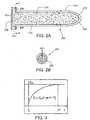
- micro-needle 200having a tubular configuration defined by outer plating 214 and lumen 220.
- Lumen 220has a volume generally in the range from about 25 to_280 nL, and more typically in the range from about 25 to 160 nL.
- the entirety of its lengthis hollow.
- Micro-needle 200may have the same or similar length and diameter dimensions as discussed above, but may instead have smaller dimensions as the electrochemical cell is located outside micro-needle lumen 220 rather than housed within it.
- Electrode 208defines a surface which circumferentially extends from proximal end 205 of micro-needle 200.
- electrode 208is in the form of an annular ring, as shown in Fig. 2B but may have any suitable shape, such as square or rectangular.
- Electrode 212is spaced proximally from electrode 208, defining a spacing there between which functions as the reaction zone 210 of the electrochemical cell.
- Electrode 212preferably has a shape and size that correspond to the shape and size of electrode 208.
- electrode 212preferably has a circular disk shape and a diameter the same as the outer diameter of electrode 208. This diameter dimension is generally in the range from about 600 to 800 ⁇ m, and typically does not exceed 1mm.
- the inner diameter of electrode 108preferably matches the diameter of outer plating 214, and thus has values mentioned above.
- At least the surfaces of the electrodes of Figs. 1 and 2 that face the reaction zones 110 and 210 within micro-needles 100 and 200, respectively,are comprised of highly conductive metal, such as palladium, gold, platinum, silver, iridium, carbon, doped indium tin oxide, stainless steel and the like, or a combination of such materials. Most typically the metal is gold, platinum or palladium.
- each electrodecan be made up of an inert support or backing substrate on the surface of which is a thin layer of the metal component ( e . g ., an electroplated metal layer) of the electrode.
- the constituent transfer medium of the sampling means of the present inventionmay occupy the entire volume of the reaction zones 110 and 210, respectively, and at least a portion of each micro-needle needle lumen 120 and 220, respectively, but may completely fill the lumen.
- the constituent transfer mediumis preferably made of a water-based gel material or matrix having a high affinity for water, i . e ., is highly water-absorbent.
- the hydrophilic gelhelps to precondition the electrodes and reconstitute the reagent material in preparation for the electrochemical measurement of target analytes.
- the transfer medium's ability to absorb fluids, particularly water,is dependent upon the extent to which the transfer medium is saturated prior to being exposed to fluid.
- the constituent transfer mediumis preferably provided in a fully saturated state prior to insertion of the micro-needle into the skin.
- interstitial fluidfor example, is about 98% water, the reduction in diffusion time through the gel may be significant in certain applications.
- the speed at which they reach the reaction zonewill vary depending on the size of the molecules of the constituents. Generally, the smaller the molecule the faster the diffusion rate through the gel. As many commonly targeted analytes, such as glucose, electrolytes, ascorbic acid, uric acid, etc., have small molecules, these analytes will diffuse through the gel matrix faster than other components of the interstitial fluid comprised of larger molecules.
- the concentration kinetics of the selected hydrogelis that of a first order system. As such, the constituent transfer rate and the analyte concentration level of the biological fluid are more predictable.
- the value of the time constantdepends on several factors: (1) the area of the interface between the hydrogel and the interstitial fluid ( i . e ., the surface area of the opening defined by edge 116 and 216 of micro-needles 100 and 200, respectively, (2) the volume of the hydrogel, and (3) the transport characteristics of the target analyte through the particular hydrogel material used.
- the graph of Fig. 3depicts the first order system described in the above equation.
- the dependent axisrepresents time (t) where t o is the point in time at which a micro-needle is inserted into the skin.
- t ois the point in time at which a micro-needle is inserted into the skin.
- the time it takes for the constituent concentration in the hydrogel to reach equilibrium with that of the biological fluid present at the distal opening of the micro-needleis generally no more than about 5 times the time constant of the system. If the time to achieve equilibrium is impractical for a given application, the micro-needle may be removed from the skin prior to reaching equilibrium and then the analyte concentration level within the patient (C o ) can be calculated based on the first order characteristics of the system. Alternately, the time duration of contact between the micro-needle and the interstitial fluid may be controlled ( i.e., fixed) and C o can be derived based on the first order equation above.
- Gel materials suitable for use as the constituent transfer medium of the present inventioninclude natural gels made up of naturally occurring polymers, such as agarose, gelatin, mucopolysaccharide, starch and the like, and synthetic gels made up, at least in part, of synthetic polymers, such as anyone of the neutral water-soluble polymers or polyelectrolytes ( i . e ., synthetic or natural polymers which form ionic charges when dissolved in water), such as polyvinyl pyrrolidone, polyethylene glycol, polyacrylic acid, polyvinyl alcohol, polyacrylamide, and copolymers thereof.
- synthetic polymerssuch as anyone of the neutral water-soluble polymers or polyelectrolytes ( i . e ., synthetic or natural polymers which form ionic charges when dissolved in water), such as polyvinyl pyrrolidone, polyethylene glycol, polyacrylic acid, polyvinyl alcohol, polyacrylamide, and copolymers thereof.
- a redox reagentis typically employed within the reaction zone within the electrochemical cell.
- the redox reagent materialis typically deposited on at least one of the facing surfaces of the two electrodes whereby biological fluid present in the reaction zone chemically reacts with the reagent material.
- the reagentis preferably coated or deposited on the surface(s) by means of dip coating.
- the reagent being usedis selected based on the analyte targeted for detection.
- the interaction of the reagent system and the corresponding constituent or analyteis employed in the electrochemical measurement protocol to determine the concentration of the target analyte or constituent in the cell.
- the reagent system present in the reaction areatypically includes at least an enzyme(s) and a mediator.
- the enzyme member(s) of the reagent systemis an enzyme or a plurality of enzymes that work in concert to oxidize the analyte of interest.
- the enzyme component of the reagent systemis made up of a single analyte oxidizing enzyme or a collection of two or more enzymes that work in concert to oxidize the analyte of interest.
- Enzymes of interestinclude oxidases, dehydrogenases, lipases, kinases, diaphorases, quinoproteins and the like.
- the specific enzyme present in the reaction areadepends on the particular analyte for which the electrochemical test strip is designed to detect, where representative enzymes include: glucose oxidase, glucose dehydrogenase, cholesterol esterase, cholesterol oxidase, lipoprotein lipase, glycerol kinase, glycerol-3-phosphate oxidase, lactate oxidase, lactate dehydrogenase, pyruvate oxidase, alcohol oxidase, bilirubin oxidase, uricase, and the like.
- the enzyme component of the reagent systemis a glucose-oxidizing enzyme (e.g., a glucose oxidase or glucose dehydrogenase).
- the second component of the reagent systemis a mediator component, which is made up of one or more mediator agents.
- mediator agentsinclude: ferricyanide, phenazine ethosulphate, phenazine methosulfate, pheylenediamine, 1-methoxy-phenazine methosulfate, 2,6-dimethyl-1,4-benzoquinone, 2,5-dichloro-1,4-benzoquinone, ferrocene derivatives, osmium bipyridyl complexes, ruthenium complexes and the like.
- the mediator of particular interestis ferricyanide.
- buffering agentse . g ., citraconate, citrate, phosphate
- Good buffersand the like.
- the reagentis generally present in dry form.
- the amounts of the various componentsmay vary wherein the amount of enzyme component typically ranges from about 0.1 to 10% by weight.
- the reference and working electrodes of the electrochemical cellare in electrical communication with a control means that sets the input reference signal transmitted to the electrochemical cell, receives the output signal from the electrochemical cell and then derives the concentration level of the analyte within the sample from the output signal.
- the control meansprovides a means for applying an electrical current between the two electrodes, measuring a change in the current over time and relating the observed change in current to the concentration of analyte present in the electrochemical cell.
- the concentration of the analyte in the patient's bloodis then derived, the numerical value of which is preferably provided as an output signal to a display means.
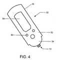
- control and display meansare integrally housed within a hand-held control unit such as that illustrated in Fig. 4.
- the control unitpreferably also provides a means of securing or holding one or more micro-needles or an array of micro-needles in a position and arrangement suitable for the particular sampling and measuring application at hand.
- Sensor system 50comprises a hand-held control unit 52 and a sensor device 10 operatively mounted to distal end 54 of control unit 52.
- Sensor device 10includes array of the micro-needles of the present invention, such as micro-needle 100 of Figs. 1 and 2.
- Control unit 52has a housing 56, preferably made of a medical grade plastic material, having a low-profile configuration which houses a means (not shown) for controlling the measurement means of sensor device 10, i.e., generating and transmitting input reference signals to the electrochemical cell of micro-needle 100 and receiving output measurement signals from the cell.
- a software algorithm programmed within control unit 52automatically calculates and determines the concentration of the target analyte in the biological sample upon receipt of the output signal.
- the concentration level(among other desired information) is then transmitted to an external display means or screen 58 that displays information to the user.
- Control interface buttons 60are provided to allow the user to input information, such as the type of analyte targeted for measurement, to the control means.
- Sensor device 10is electrically and physically coupled to control unit 52. Electrical communication between the two is established by means of conductive contacts (not shown) on device 10 and corresponding electrical traces (not shown) within control unit 52. Preferably, device 10 and control unit 52 are physically coupled by a quick lock-and-release mechanism (many of which are commonly known) such that a used sensor device can be easily removed and replaced. Control unit 52 is preferably reusable and usable with any number of sensor devices of the subject invention. These features facilitate the taking of multiple samples and measurements in an efficient and rapid manner.
- Also provided by the subject inventionare methods for using the subject devices and sensor systems to determine the concentration of an analyte in a physiological sample.
- a variety of different analytesmay be detected using the subject sensor systems, where representative analytes include glucose, cholesterol, lactate, alcohol, and the like.
- the first stepis to provide a sensor device 10 having one or more micro-needles 100 of the present invention.
- sensor device 10is particularly configured ( i . e ., containing the appropriate reagent) for targeting the analyte(s) of interest.
- the sensor device 10is operatively engaged and interfaced with a control unit 52 that can be manually held and controlled by the user.
- Control unit 52is programmed for testing the targeted analyte(s).
- the userpositions sensor device 10 over a selected area of the patient's skin, and, with slight pressure, the array of micro-needles 100 of sensor device 10 are caused to penetrate into the skin.
- the depth to which the micro-needles 100 are insertedwill depend on the length of the respective micro-needles or by some other means associated with the sensor unit 10 for limiting the insertion depth.
- an amounti . e ., a sample
- constituents of the biological fluid present at the open tips 102 of micro-needles 100is absorbed by the gel-based, constituent transfer medium into lumens 120 of the respective micro-needles by means of osmosis.
- the targeted analyte(s)chemically reacts with the selected reagent(s) to form electroactive products.
- the electroactive productsare then either oxidized or reduced by the optional mediator or directly by the working electrode 108.
- the resulting output signal levelis then conducted to the control unit by electrode 108.
- a software algorithm programmed within control unit 52then automatically determines the differential between the output and reference signals, derives the concentration of analyte in the sample from this differential value, and then derives the corresponding concentration level of the selected analyte(s) in the patient's blood. Any or all of these values may be displayed by display means or screen 58.
- a devicesuch as control unit 52 which automatically calculates and determines the concentration of a selected analyte in a biological sample and/or in the patient's system, such that a user need only insert a micro-needle of the subject invention into the patient's skin and then read the final analyte concentration result from a display of the device, is further described in U.S. Patent No. 6,193,873 entitled “Sample Detection to Initiate Timing of an Electrochemical Assay," the disclosure of which is herein incorporated by reference.
- kits for use in practicing the subject methodsinclude at least one subject sensor device having one or more micro-needles.
- the kitsmay also include a reusable or disposable control unit that may be used with reusable or disposable sensor devices of the kit or from other kits of the subject invention.
- These kitsmay include sensors having an array of micro-needles having the same or different lengths.
- Certain kitsmay include various sensors each containing the same or different reagents.
- kitspreferably include instructions for using the subject sensors in the determination of an analyte concentration in a physiological sample. These instructions may be present on one or more of the packaging, a label insert, or containers present in the kits, and the like.
- the subject inventionsare easy to use and can provide for analyte testing without the need to cut or lance the skin and without minimal or no pain and blood. As such, the subject invention represents a significant contribution to the field.
Landscapes
- Health & Medical Sciences (AREA)
- Life Sciences & Earth Sciences (AREA)
- Engineering & Computer Science (AREA)
- Physics & Mathematics (AREA)
- Biomedical Technology (AREA)
- General Health & Medical Sciences (AREA)
- Pathology (AREA)
- Molecular Biology (AREA)
- Biophysics (AREA)
- Veterinary Medicine (AREA)
- Public Health (AREA)
- Animal Behavior & Ethology (AREA)
- Surgery (AREA)
- Medical Informatics (AREA)
- Heart & Thoracic Surgery (AREA)
- Hematology (AREA)
- Manufacturing & Machinery (AREA)
- Chemical & Material Sciences (AREA)
- Optics & Photonics (AREA)
- Chemical Kinetics & Catalysis (AREA)
- General Chemical & Material Sciences (AREA)
- Analytical Chemistry (AREA)
- Medicinal Chemistry (AREA)
- Food Science & Technology (AREA)
- Biochemistry (AREA)
- Urology & Nephrology (AREA)
- General Physics & Mathematics (AREA)
- Immunology (AREA)
- Measurement Of The Respiration, Hearing Ability, Form, And Blood Characteristics Of Living Organisms (AREA)
- Investigating Or Analysing Biological Materials (AREA)
Abstract


Description
Claims (10)
- A biological fluid constituent sampling and analyte concentrationmeasurement device comprising:(a) an elongated member having an open distal end configured to pierce askin surface and to provide access to the biological fluid;(b) concentrically-spaced electrodes positioned within the elongatedmember that define an electrochemical cell for measuring the concentration of a targetanalyte within the biological fluid; and(c) a constituent transfer medium comprising a hydrophilic material influid communication with the elongated member and with the electrochemical, wherein theconstituent transfer medium transfers at least one biological fluid constituent present at theopen distal end of the elongated member into the electrochemical cell.
- The device of claim 1 wherein the elongated member comprises alumen, wherein the open distal end provides a passageway into the lumen.
- A device for sampling biological fluid constituents and measuring theconcentration of at least one target constituent in the biological fluid, comprising:a first electrode having a first length;a second electrode having a second length greater than the first length andconcentrically positioned about and spaced apart from the first electrode, wherein the secondelectrode is configured for piercing the skin; anda hydrogel material within the space between the first and second electrodes.
- The device according to claim 3 having a penetration length no deeperthan the dermis.
- The device according to claim 3 wherein the second electrode has anopen distal end and defines a space within the device and wherein the space is substantiallyfilled with the hydrogel material.
- A micro-needle for sampling a biological fluid constituents andmeasuring a target constituent within the biological fluid, comprising:a core having a length;a first electrode coaxially conformed about the core length;a second electrode coaxially spaced-apart from the first electrode and havinga length that extends beyond the core length and terminates at an open tip; anda hydrogel material located between the first and second electrodes; anda reagent contained within the micro-needle wherein the reagent is selected based onthe target constituent.
- A biological fluid constituent sampling and analyte concentrationmeasurement device, said device comprising:(a) an elongated hollow member having an open distal end configured topierce a skin surface and to provide access to the biological fluid and a proximal end;(b) two parallely-spaced electrodes positioned at the proximal end of theelongated hollow sampling means that define an electrochemical cell for measuring theconcentration of analyte within the biological fluid; and(c) a constituent transfer medium comprising a water-absorbent materialin fluid communication with the elongated hollow member and with the electrochemical cell,wherein the constituent transfer medium transfers biological fluid present at the open distalend of the at least one piercing member into the electrochemical cell.
- A system for sampling biological fluid constituents from the skin of apatient and measuring a target constituent within the biological fluid, the systemcomprising:(a) at least one micro-needle at least a portion of which is hollow andhaving an open distal end for accessing the biological fluid;(b) an electrochemical cell associated with the micro-needle, the cellcomprising a reference electrode and a working electrode spaced apart from eachother;(c) a water-absorbent gel matrix at least partially contained within thehollow portion of the micro-needle and the space between the electrodes; and(d) a control unit in electrical communication with the electrochemicalcell, comprising:(1) means for sending an electrical reference signal to the referenceelectrode and for receiving an electrical output signal from the working electrode,and(2) a software algorithm which automatically calculates and determinesthe concentration of the target constituent in the biological fluid upon receipt of theelectrical output signal.
- A method for determining the concentration of at least one targetconstituent contained within biological fluid, the method comprising the steps of:providing at least one micro-needle comprising an open distal end and alumen;providing an electrochemical cell within the lumen, the electrochemical cellcomprising a concentrically-layered electrode configuration;inserting the open distal end of the micro-needle into the skin to a selecteddepth;transferring a sample of at least one target constituent within the biologicalfluid present at the open distal end through the lumen and into the electrochemical cell;providing a first electrical signal to the electrochemical cell; andreceiving a second electrical signal generated by the electrochemical cell,wherein the second electrical signal is representative of the concentration the constituent inthe biological fluid.
- A method for determining the concentration of at least one targetconstituent contained within biological fluid, the method comprising the steps of:providing at least one hollow micro-needle comprising an open distal end, anopen proximal end and a lumen extending there between;providing an electrochemical cell in fluid communication with the hollow micro-needle,the cell comprising a parallely-spaced electrode configuration, wherein the electrodeconfiguration is positioned at the open proximal end of the hollow micro-needlesubstantially transverse to the micro-needle;inserting the open distal end of the hollow micro-needle into the skin to aselected depth;transferring a sample of the at least one targeted biological fluid constituentpresent at the open distal end of the hollow micro-needle into the electrochemical cell;providing a first electrical signal to the electrochemical cell; andreceiving a second electrical signal generated by the electrochemical cell,wherein the second electrical signal is representative of the concentration the constituent inthe biological fluid.
Applications Claiming Priority (2)
| Application Number | Priority Date | Filing Date | Title |
|---|---|---|---|
| US09/878,742US6793632B2 (en) | 2001-06-12 | 2001-06-12 | Percutaneous biological fluid constituent sampling and measurement devices and methods |
| US878742 | 2001-06-12 |
Publications (2)
| Publication Number | Publication Date |
|---|---|
| EP1266607A2true EP1266607A2 (en) | 2002-12-18 |
| EP1266607A3 EP1266607A3 (en) | 2004-07-21 |
Family
ID=25372738
Family Applications (1)
| Application Number | Title | Priority Date | Filing Date |
|---|---|---|---|
| EP02254049AWithdrawnEP1266607A3 (en) | 2001-06-12 | 2002-06-11 | Percutaneous biological fluid constituent sampling and measurement devices and methods |
Country Status (16)
| Country | Link |
|---|---|
| US (2) | US6793632B2 (en) |
| EP (1) | EP1266607A3 (en) |
| JP (1) | JP2003038465A (en) |
| KR (1) | KR20020094896A (en) |
| CN (2) | CN1391102A (en) |
| AR (1) | AR034378A1 (en) |
| AU (1) | AU784882B2 (en) |
| CA (1) | CA2390330A1 (en) |
| CZ (1) | CZ20022023A3 (en) |
| HK (1) | HK1049595A1 (en) |
| IL (2) | IL150098A (en) |
| MX (1) | MXPA02005618A (en) |
| PL (1) | PL354420A1 (en) |
| RU (1) | RU2002115721A (en) |
| SG (1) | SG115479A1 (en) |
| TW (1) | TWI236364B (en) |
Cited By (46)
| Publication number | Priority date | Publication date | Assignee | Title |
|---|---|---|---|---|
| EP1613370A4 (en)* | 2003-03-31 | 2007-05-02 | Rosedale Medical Inc | Body fluid sampling constructions and techniques |
| WO2007145897A3 (en)* | 2006-06-05 | 2008-03-20 | Mit Llp | Iontosonic-microneedle biosensor apparatus and methods |
| WO2008042625A3 (en)* | 2006-10-04 | 2008-08-21 | Dexcom Inc | Analyte sensor |
| US8287453B2 (en) | 2003-12-05 | 2012-10-16 | Dexcom, Inc. | Analyte sensor |
| US8311749B2 (en) | 2003-08-01 | 2012-11-13 | Dexcom, Inc. | Transcutaneous analyte sensor |
| US8360994B2 (en) | 2005-09-30 | 2013-01-29 | Intuity Medical, Inc. | Arrangement for body fluid sample extraction |
| US8801631B2 (en) | 2005-09-30 | 2014-08-12 | Intuity Medical, Inc. | Devices and methods for facilitating fluid transport |
| US8812072B2 (en) | 2004-07-13 | 2014-08-19 | Dexcom, Inc. | Transcutaneous medical device with variable stiffness |
| US8886273B2 (en) | 2003-08-01 | 2014-11-11 | Dexcom, Inc. | Analyte sensor |
| US8919605B2 (en) | 2009-11-30 | 2014-12-30 | Intuity Medical, Inc. | Calibration material delivery devices and methods |
| US8969097B2 (en) | 2005-06-13 | 2015-03-03 | Intuity Medical, Inc. | Analyte detection devices and methods with hematocrit-volume correction and feedback control |
| WO2015056176A1 (en)* | 2013-10-15 | 2015-04-23 | Ecole Polytechnique Federale De Lausanne (Epfl) | Sensing tip with electrical impedance sensor |
| US9050413B2 (en) | 2004-02-26 | 2015-06-09 | Dexcom, Inc. | Integrated delivery device for continuous glucose sensor |
| US9095292B2 (en) | 2003-03-24 | 2015-08-04 | Intuity Medical, Inc. | Analyte concentration detection devices and methods |
| US9636051B2 (en) | 2008-06-06 | 2017-05-02 | Intuity Medical, Inc. | Detection meter and mode of operation |
| US9741139B2 (en) | 2007-06-08 | 2017-08-22 | Dexcom, Inc. | Integrated medicament delivery device for use with continuous analyte sensor |
| US9763609B2 (en) | 2003-07-25 | 2017-09-19 | Dexcom, Inc. | Analyte sensors having a signal-to-noise ratio substantially unaffected by non-constant noise |
| US9782114B2 (en) | 2011-08-03 | 2017-10-10 | Intuity Medical, Inc. | Devices and methods for body fluid sampling and analysis |
| US9833183B2 (en) | 2008-05-30 | 2017-12-05 | Intuity Medical, Inc. | Body fluid sampling device—sampling site interface |
| US10052055B2 (en) | 2003-08-01 | 2018-08-21 | Dexcom, Inc. | Analyte sensor |
| US10052051B2 (en) | 2002-05-22 | 2018-08-21 | Dexcom, Inc. | Silicone based membranes for use in implantable glucose sensors |
| US10278580B2 (en) | 2004-02-26 | 2019-05-07 | Dexcom, Inc. | Integrated medicament delivery device for use with continuous analyte sensor |
| US10330667B2 (en) | 2010-06-25 | 2019-06-25 | Intuity Medical, Inc. | Analyte monitoring methods and systems |
| US10349873B2 (en) | 2006-10-04 | 2019-07-16 | Dexcom, Inc. | Analyte sensor |
| US10376143B2 (en) | 2003-07-25 | 2019-08-13 | Dexcom, Inc. | Analyte sensors having a signal-to-noise ratio substantially unaffected by non-constant noise |
| US10383556B2 (en) | 2008-06-06 | 2019-08-20 | Intuity Medical, Inc. | Medical diagnostic devices and methods |
| US10524703B2 (en) | 2004-07-13 | 2020-01-07 | Dexcom, Inc. | Transcutaneous analyte sensor |
| US10602968B2 (en) | 2008-03-25 | 2020-03-31 | Dexcom, Inc. | Analyte sensor |
| US10610136B2 (en) | 2005-03-10 | 2020-04-07 | Dexcom, Inc. | System and methods for processing analyte sensor data for sensor calibration |
| US10653835B2 (en) | 2007-10-09 | 2020-05-19 | Dexcom, Inc. | Integrated insulin delivery system with continuous glucose sensor |
| US10667733B2 (en) | 2009-09-30 | 2020-06-02 | Dexcom, Inc. | Transcutaneous analyte sensor |
| US10729386B2 (en) | 2013-06-21 | 2020-08-04 | Intuity Medical, Inc. | Analyte monitoring system with audible feedback |
| US10772550B2 (en) | 2002-02-08 | 2020-09-15 | Intuity Medical, Inc. | Autonomous, ambulatory analyte monitor or drug delivery device |
| US10791928B2 (en) | 2007-05-18 | 2020-10-06 | Dexcom, Inc. | Analyte sensors having a signal-to-noise ratio substantially unaffected by non-constant noise |
| US10813577B2 (en) | 2005-06-21 | 2020-10-27 | Dexcom, Inc. | Analyte sensor |
| US10898113B2 (en) | 2003-12-09 | 2021-01-26 | Dexcom, Inc. | Signal processing for continuous analyte sensor |
| US10980461B2 (en) | 2008-11-07 | 2021-04-20 | Dexcom, Inc. | Advanced analyte sensor calibration and error detection |
| US11000215B1 (en) | 2003-12-05 | 2021-05-11 | Dexcom, Inc. | Analyte sensor |
| US11102306B2 (en) | 2008-02-21 | 2021-08-24 | Dexcom, Inc. | Systems and methods for processing, transmitting and displaying sensor data |
| US11331022B2 (en) | 2017-10-24 | 2022-05-17 | Dexcom, Inc. | Pre-connected analyte sensors |
| US11350862B2 (en) | 2017-10-24 | 2022-06-07 | Dexcom, Inc. | Pre-connected analyte sensors |
| US11399745B2 (en) | 2006-10-04 | 2022-08-02 | Dexcom, Inc. | Dual electrode system for a continuous analyte sensor |
| WO2022195236A1 (en)* | 2021-03-19 | 2022-09-22 | Pkvitality | Irritation-limiting sensor for body monitoring device |
| US11564602B2 (en) | 2003-11-19 | 2023-01-31 | Dexcom, Inc. | Integrated receiver for continuous analyte sensor |
| US11633133B2 (en) | 2003-12-05 | 2023-04-25 | Dexcom, Inc. | Dual electrode system for a continuous analyte sensor |
| US12409515B2 (en) | 2009-07-02 | 2025-09-09 | Dexcom, Inc. | Continuous analyte sensors and methods of making same |
Families Citing this family (167)
| Publication number | Priority date | Publication date | Assignee | Title |
|---|---|---|---|---|
| SE9700384D0 (en)* | 1997-02-04 | 1997-02-04 | Biacore Ab | Analytical method and apparatus |
| US7657297B2 (en) | 2004-05-03 | 2010-02-02 | Dexcom, Inc. | Implantable analyte sensor |
| US7192450B2 (en) | 2003-05-21 | 2007-03-20 | Dexcom, Inc. | Porous membranes for use with implantable devices |
| US6862465B2 (en) | 1997-03-04 | 2005-03-01 | Dexcom, Inc. | Device and method for determining analyte levels |
| US8527026B2 (en) | 1997-03-04 | 2013-09-03 | Dexcom, Inc. | Device and method for determining analyte levels |
| US6001067A (en) | 1997-03-04 | 1999-12-14 | Shults; Mark C. | Device and method for determining analyte levels |
| US6036924A (en) | 1997-12-04 | 2000-03-14 | Hewlett-Packard Company | Cassette of lancet cartridges for sampling blood |
| US6391005B1 (en) | 1998-03-30 | 2002-05-21 | Agilent Technologies, Inc. | Apparatus and method for penetration with shaft having a sensor for sensing penetration depth |
| US8641644B2 (en) | 2000-11-21 | 2014-02-04 | Sanofi-Aventis Deutschland Gmbh | Blood testing apparatus having a rotatable cartridge with multiple lancing elements and testing means |
| JP2002228668A (en)* | 2001-01-31 | 2002-08-14 | Shimadzu Corp | Auto sampler |
| JP4209767B2 (en) | 2001-06-12 | 2009-01-14 | ペリカン テクノロジーズ インコーポレイテッド | Self-optimized cutting instrument with adaptive means for temporary changes in skin properties |
| US6721586B2 (en)* | 2001-06-12 | 2004-04-13 | Lifescan, Inc. | Percutaneous biological fluid sampling and analyte measurement devices and methods |
| US9226699B2 (en) | 2002-04-19 | 2016-01-05 | Sanofi-Aventis Deutschland Gmbh | Body fluid sampling module with a continuous compression tissue interface surface |
| US7041068B2 (en) | 2001-06-12 | 2006-05-09 | Pelikan Technologies, Inc. | Sampling module device and method |
| US7344507B2 (en) | 2002-04-19 | 2008-03-18 | Pelikan Technologies, Inc. | Method and apparatus for lancet actuation |
| US9795747B2 (en) | 2010-06-02 | 2017-10-24 | Sanofi-Aventis Deutschland Gmbh | Methods and apparatus for lancet actuation |
| AU2002344825A1 (en) | 2001-06-12 | 2002-12-23 | Pelikan Technologies, Inc. | Method and apparatus for improving success rate of blood yield from a fingerstick |
| EP1395185B1 (en) | 2001-06-12 | 2010-10-27 | Pelikan Technologies Inc. | Electric lancet actuator |
| US6793632B2 (en)* | 2001-06-12 | 2004-09-21 | Lifescan, Inc. | Percutaneous biological fluid constituent sampling and measurement devices and methods |
| US7749174B2 (en) | 2001-06-12 | 2010-07-06 | Pelikan Technologies, Inc. | Method and apparatus for lancet launching device intergrated onto a blood-sampling cartridge |
| WO2002101359A2 (en) | 2001-06-12 | 2002-12-19 | Pelikan Technologies, Inc. | Integrated blood sampling analysis system with multi-use sampling module |
| US9427532B2 (en) | 2001-06-12 | 2016-08-30 | Sanofi-Aventis Deutschland Gmbh | Tissue penetration device |
| JP4272051B2 (en) | 2001-06-12 | 2009-06-03 | ペリカン テクノロジーズ インコーポレイテッド | Blood sampling apparatus and method |
| US6837988B2 (en)* | 2001-06-12 | 2005-01-04 | Lifescan, Inc. | Biological fluid sampling and analyte measurement devices and methods |
| US8337419B2 (en) | 2002-04-19 | 2012-12-25 | Sanofi-Aventis Deutschland Gmbh | Tissue penetration device |
| US7981056B2 (en) | 2002-04-19 | 2011-07-19 | Pelikan Technologies, Inc. | Methods and apparatus for lancet actuation |
| US6702857B2 (en) | 2001-07-27 | 2004-03-09 | Dexcom, Inc. | Membrane for use with implantable devices |
| US7344894B2 (en) | 2001-10-16 | 2008-03-18 | Agilent Technologies, Inc. | Thermal regulation of fluidic samples within a diagnostic cartridge |
| US20050049632A1 (en)* | 2002-01-22 | 2005-03-03 | Yukio Inokuti | Ceramic-coated instruments for medical use, ceramic-coated instruments for studying living organisms and process for producing the same |
| JP2004121064A (en)* | 2002-10-01 | 2004-04-22 | Jfe Steel Kk | Ceramic coated needle for gene control |
| CN1292717C (en)* | 2002-01-22 | 2007-01-03 | 杰富意钢铁株式会社 | Ceramic coated medical and biological research instruments and methods of making the same |
| US7524293B2 (en) | 2002-04-19 | 2009-04-28 | Pelikan Technologies, Inc. | Method and apparatus for penetrating tissue |
| US8267870B2 (en) | 2002-04-19 | 2012-09-18 | Sanofi-Aventis Deutschland Gmbh | Method and apparatus for body fluid sampling with hybrid actuation |
| US7892183B2 (en) | 2002-04-19 | 2011-02-22 | Pelikan Technologies, Inc. | Method and apparatus for body fluid sampling and analyte sensing |
| US7229458B2 (en) | 2002-04-19 | 2007-06-12 | Pelikan Technologies, Inc. | Method and apparatus for penetrating tissue |
| US7648468B2 (en) | 2002-04-19 | 2010-01-19 | Pelikon Technologies, Inc. | Method and apparatus for penetrating tissue |
| US7371247B2 (en) | 2002-04-19 | 2008-05-13 | Pelikan Technologies, Inc | Method and apparatus for penetrating tissue |
| US7976476B2 (en) | 2002-04-19 | 2011-07-12 | Pelikan Technologies, Inc. | Device and method for variable speed lancet |
| US7674232B2 (en) | 2002-04-19 | 2010-03-09 | Pelikan Technologies, Inc. | Method and apparatus for penetrating tissue |
| US9795334B2 (en) | 2002-04-19 | 2017-10-24 | Sanofi-Aventis Deutschland Gmbh | Method and apparatus for penetrating tissue |
| US7491178B2 (en) | 2002-04-19 | 2009-02-17 | Pelikan Technologies, Inc. | Method and apparatus for penetrating tissue |
| US7244265B2 (en) | 2002-04-19 | 2007-07-17 | Pelikan Technologies, Inc. | Method and apparatus for penetrating tissue |
| WO2003088824A2 (en) | 2002-04-19 | 2003-10-30 | Pelikan Technologies, Inc. | Device and method for variable speed lancet |
| US8784335B2 (en) | 2002-04-19 | 2014-07-22 | Sanofi-Aventis Deutschland Gmbh | Body fluid sampling device with a capacitive sensor |
| US8579831B2 (en) | 2002-04-19 | 2013-11-12 | Sanofi-Aventis Deutschland Gmbh | Method and apparatus for penetrating tissue |
| US7297122B2 (en) | 2002-04-19 | 2007-11-20 | Pelikan Technologies, Inc. | Method and apparatus for penetrating tissue |
| US7410468B2 (en) | 2002-04-19 | 2008-08-12 | Pelikan Technologies, Inc. | Method and apparatus for penetrating tissue |
| US9248267B2 (en) | 2002-04-19 | 2016-02-02 | Sanofi-Aventis Deustchland Gmbh | Tissue penetration device |
| US8702624B2 (en) | 2006-09-29 | 2014-04-22 | Sanofi-Aventis Deutschland Gmbh | Analyte measurement device with a single shot actuator |
| US9314194B2 (en) | 2002-04-19 | 2016-04-19 | Sanofi-Aventis Deutschland Gmbh | Tissue penetration device |
| US7374544B2 (en) | 2002-04-19 | 2008-05-20 | Pelikan Technologies, Inc. | Method and apparatus for penetrating tissue |
| US7141058B2 (en) | 2002-04-19 | 2006-11-28 | Pelikan Technologies, Inc. | Method and apparatus for a body fluid sampling device using illumination |
| US8372016B2 (en) | 2002-04-19 | 2013-02-12 | Sanofi-Aventis Deutschland Gmbh | Method and apparatus for body fluid sampling and analyte sensing |
| US7901362B2 (en) | 2002-04-19 | 2011-03-08 | Pelikan Technologies, Inc. | Method and apparatus for penetrating tissue |
| US7331931B2 (en) | 2002-04-19 | 2008-02-19 | Pelikan Technologies, Inc. | Method and apparatus for penetrating tissue |
| US7485128B2 (en) | 2002-04-19 | 2009-02-03 | Pelikan Technologies, Inc. | Method and apparatus for penetrating tissue |
| US8360992B2 (en) | 2002-04-19 | 2013-01-29 | Sanofi-Aventis Deutschland Gmbh | Method and apparatus for penetrating tissue |
| US7232451B2 (en) | 2002-04-19 | 2007-06-19 | Pelikan Technologies, Inc. | Method and apparatus for penetrating tissue |
| US8221334B2 (en) | 2002-04-19 | 2012-07-17 | Sanofi-Aventis Deutschland Gmbh | Method and apparatus for penetrating tissue |
| US7708701B2 (en) | 2002-04-19 | 2010-05-04 | Pelikan Technologies, Inc. | Method and apparatus for a multi-use body fluid sampling device |
| US7717863B2 (en) | 2002-04-19 | 2010-05-18 | Pelikan Technologies, Inc. | Method and apparatus for penetrating tissue |
| US7547287B2 (en) | 2002-04-19 | 2009-06-16 | Pelikan Technologies, Inc. | Method and apparatus for penetrating tissue |
| US7563232B2 (en) | 2002-04-19 | 2009-07-21 | Pelikan Technologies, Inc. | Method and apparatus for penetrating tissue |
| US7291117B2 (en) | 2002-04-19 | 2007-11-06 | Pelikan Technologies, Inc. | Method and apparatus for penetrating tissue |
| US7909778B2 (en) | 2002-04-19 | 2011-03-22 | Pelikan Technologies, Inc. | Method and apparatus for penetrating tissue |
| US8574895B2 (en) | 2002-12-30 | 2013-11-05 | Sanofi-Aventis Deutschland Gmbh | Method and apparatus using optical techniques to measure analyte levels |
| US7120483B2 (en)* | 2003-01-13 | 2006-10-10 | Isense Corporation | Methods for analyte sensing and measurement |
| US7228162B2 (en)* | 2003-01-13 | 2007-06-05 | Isense Corporation | Analyte sensor |
| US7134999B2 (en) | 2003-04-04 | 2006-11-14 | Dexcom, Inc. | Optimized sensor geometry for an implantable glucose sensor |
| US7875293B2 (en)* | 2003-05-21 | 2011-01-25 | Dexcom, Inc. | Biointerface membranes incorporating bioactive agents |
| DE602004028463D1 (en) | 2003-05-30 | 2010-09-16 | Pelikan Technologies Inc | METHOD AND DEVICE FOR INJECTING LIQUID |
| US7850621B2 (en) | 2003-06-06 | 2010-12-14 | Pelikan Technologies, Inc. | Method and apparatus for body fluid sampling and analyte sensing |
| US8460243B2 (en) | 2003-06-10 | 2013-06-11 | Abbott Diabetes Care Inc. | Glucose measuring module and insulin pump combination |
| WO2006001797A1 (en) | 2004-06-14 | 2006-01-05 | Pelikan Technologies, Inc. | Low pain penetrating |
| EP1635700B1 (en) | 2003-06-13 | 2016-03-09 | Sanofi-Aventis Deutschland GmbH | Apparatus for a point of care device |
| US7146202B2 (en)* | 2003-06-16 | 2006-12-05 | Isense Corporation | Compound material analyte sensor |
| US7722536B2 (en) | 2003-07-15 | 2010-05-25 | Abbott Diabetes Care Inc. | Glucose measuring device integrated into a holster for a personal area network device |
| US20050015019A1 (en)* | 2003-07-18 | 2005-01-20 | Yamatake Corporation | Sampling syringe unit, sampling device and sampling method for sampling blood or body fluid |
| US7460898B2 (en)* | 2003-12-05 | 2008-12-02 | Dexcom, Inc. | Dual electrode system for a continuous analyte sensor |
| WO2007120442A2 (en) | 2003-07-25 | 2007-10-25 | Dexcom, Inc. | Dual electrode system for a continuous analyte sensor |
| US7467003B2 (en) | 2003-12-05 | 2008-12-16 | Dexcom, Inc. | Dual electrode system for a continuous analyte sensor |
| US7366556B2 (en) | 2003-12-05 | 2008-04-29 | Dexcom, Inc. | Dual electrode system for a continuous analyte sensor |
| US7424318B2 (en) | 2003-12-05 | 2008-09-09 | Dexcom, Inc. | Dual electrode system for a continuous analyte sensor |
| US8282576B2 (en) | 2003-09-29 | 2012-10-09 | Sanofi-Aventis Deutschland Gmbh | Method and apparatus for an improved sample capture device |
| EP1680014A4 (en) | 2003-10-14 | 2009-01-21 | Pelikan Technologies Inc | METHOD AND DEVICE FOR A VARIABLE USER INTERFACE |
| ATE480761T1 (en) | 2003-12-05 | 2010-09-15 | Dexcom Inc | CALIBRATION METHODS FOR A CONTINUOUSLY WORKING ANALYTICAL SENSOR |
| US8364230B2 (en) | 2006-10-04 | 2013-01-29 | Dexcom, Inc. | Analyte sensor |
| US8425416B2 (en) | 2006-10-04 | 2013-04-23 | Dexcom, Inc. | Analyte sensor |
| US8425417B2 (en) | 2003-12-05 | 2013-04-23 | Dexcom, Inc. | Integrated device for continuous in vivo analyte detection and simultaneous control of an infusion device |
| US7822454B1 (en) | 2005-01-03 | 2010-10-26 | Pelikan Technologies, Inc. | Fluid sampling device with improved analyte detecting member configuration |
| US8668656B2 (en) | 2003-12-31 | 2014-03-11 | Sanofi-Aventis Deutschland Gmbh | Method and apparatus for improving fluidic flow and sample capture |
| US7819822B2 (en)* | 2004-03-06 | 2010-10-26 | Roche Diagnostics Operations, Inc. | Body fluid sampling device |
| PT1722670E (en) | 2004-03-06 | 2013-11-27 | Hoffmann La Roche | Body fluid sampling device |
| US8792955B2 (en) | 2004-05-03 | 2014-07-29 | Dexcom, Inc. | Transcutaneous analyte sensor |
| WO2006011062A2 (en) | 2004-05-20 | 2006-02-02 | Albatros Technologies Gmbh & Co. Kg | Printable hydrogel for biosensors |
| WO2005120365A1 (en) | 2004-06-03 | 2005-12-22 | Pelikan Technologies, Inc. | Method and apparatus for a fluid sampling device |
| US9775553B2 (en) | 2004-06-03 | 2017-10-03 | Sanofi-Aventis Deutschland Gmbh | Method and apparatus for a fluid sampling device |
| EP1810185A4 (en) | 2004-06-04 | 2010-01-06 | Therasense Inc | Diabetes care host-client architecture and data management system |
| EP2335566A1 (en)* | 2004-06-16 | 2011-06-22 | iSense Corporation | Compound metal analyte sensor |
| US20070045902A1 (en) | 2004-07-13 | 2007-03-01 | Brauker James H | Analyte sensor |
| US8886272B2 (en) | 2004-07-13 | 2014-11-11 | Dexcom, Inc. | Analyte sensor |
| CN101087822B (en)* | 2004-10-28 | 2012-05-30 | 拜尔健康护理有限责任公司 | Hydrogel composition |
| US8652831B2 (en) | 2004-12-30 | 2014-02-18 | Sanofi-Aventis Deutschland Gmbh | Method and apparatus for analyte measurement test time |
| US8133178B2 (en) | 2006-02-22 | 2012-03-13 | Dexcom, Inc. | Analyte sensor |
| CA2602259A1 (en) | 2005-03-29 | 2006-10-05 | Arkal Medical, Inc. | Devices, systems, methods and tools for continuous glucose monitoring |
| US20060263763A1 (en)* | 2005-04-15 | 2006-11-23 | Simpson Peter C | Analyte sensing biointerface |
| US8060174B2 (en) | 2005-04-15 | 2011-11-15 | Dexcom, Inc. | Analyte sensing biointerface |
| US20090134043A1 (en)* | 2005-11-10 | 2009-05-28 | Kevin Ward | Non-biofouling, universal redox electrode and measurement system |
| US20080058726A1 (en)* | 2006-08-30 | 2008-03-06 | Arvind Jina | Methods and Apparatus Incorporating a Surface Penetration Device |
| US8478377B2 (en) | 2006-10-04 | 2013-07-02 | Dexcom, Inc. | Analyte sensor |
| US8447376B2 (en) | 2006-10-04 | 2013-05-21 | Dexcom, Inc. | Analyte sensor |
| US7831287B2 (en) | 2006-10-04 | 2010-11-09 | Dexcom, Inc. | Dual electrode system for a continuous analyte sensor |
| US8449464B2 (en) | 2006-10-04 | 2013-05-28 | Dexcom, Inc. | Analyte sensor |
| US8298142B2 (en) | 2006-10-04 | 2012-10-30 | Dexcom, Inc. | Analyte sensor |
| US8562528B2 (en) | 2006-10-04 | 2013-10-22 | Dexcom, Inc. | Analyte sensor |
| US8275438B2 (en) | 2006-10-04 | 2012-09-25 | Dexcom, Inc. | Analyte sensor |
| US8709709B2 (en) | 2007-05-18 | 2014-04-29 | Luoxis Diagnostics, Inc. | Measurement and uses of oxidative status |
| EP2147303B1 (en)* | 2007-05-18 | 2017-03-29 | Aytu BioScience, Inc. | Measurement and uses of oxidative status |
| US9439585B2 (en)* | 2008-02-04 | 2016-09-13 | Ascensia Diabetes Care Holdings Ag | Semiconductor based analyte sensors and methods |
| GB0802447D0 (en)* | 2008-02-09 | 2008-03-19 | Univ Manchester | Fluid extraction device, associated materials and methods |
| EP2265324B1 (en) | 2008-04-11 | 2015-01-28 | Sanofi-Aventis Deutschland GmbH | Integrated analyte measurement system |
| US8551400B2 (en)* | 2008-09-19 | 2013-10-08 | Bayer Healthcare Llc | Analyte sensors, testing apparatus and manufacturing methods |
| CN102171557B (en) | 2008-09-19 | 2016-10-19 | 安晟信医疗科技控股公司 | There is electrochemical appliance and the manufacture method thereof of the electro-chemical activity of enhancing |
| WO2010033741A1 (en)* | 2008-09-19 | 2010-03-25 | Bayer Healthcare Llc | Analyte sensors, systems, testing apparatus and manufacturing methods |
| WO2010033660A1 (en)* | 2008-09-19 | 2010-03-25 | Bayer Healthcare Llc | Lancet analyte sensors and methods of manufacturing |
| US9375169B2 (en) | 2009-01-30 | 2016-06-28 | Sanofi-Aventis Deutschland Gmbh | Cam drive for managing disposable penetrating member actions with a single motor and motor and control system |
| US20100256524A1 (en) | 2009-03-02 | 2010-10-07 | Seventh Sense Biosystems, Inc. | Techniques and devices associated with blood sampling |
| WO2011094573A1 (en) | 2010-01-28 | 2011-08-04 | Seventh Sense Biosystems, Inc. | Monitoring or feedback systems and methods |
| US8965476B2 (en) | 2010-04-16 | 2015-02-24 | Sanofi-Aventis Deutschland Gmbh | Tissue penetration device |
| WO2011156095A2 (en) | 2010-06-10 | 2011-12-15 | The Regents Of The University Of California | Textile-based printable electrodes for electrochemical sensing |
| WO2011163347A2 (en)* | 2010-06-23 | 2011-12-29 | Seventh Sense Biosystems, Inc. | Sampling devices and methods involving relatively little pain |
| US20120016308A1 (en) | 2010-07-16 | 2012-01-19 | Seventh Sense Biosystems, Inc. | Low-pressure packaging for fluid devices |
| US20130158482A1 (en) | 2010-07-26 | 2013-06-20 | Seventh Sense Biosystems, Inc. | Rapid delivery and/or receiving of fluids |
| WO2012021801A2 (en) | 2010-08-13 | 2012-02-16 | Seventh Sense Biosystems, Inc. | Systems and techniques for monitoring subjects |
| WO2012064802A1 (en) | 2010-11-09 | 2012-05-18 | Seventh Sense Biosystems, Inc. | Systems and interfaces for blood sampling |
| GB2486677A (en)* | 2010-12-22 | 2012-06-27 | Agilent Technologies Inc | Ceramic injection needle for analysis system |
| US10136845B2 (en) | 2011-02-28 | 2018-11-27 | Abbott Diabetes Care Inc. | Devices, systems, and methods associated with analyte monitoring devices and devices incorporating the same |
| ES2658709T3 (en) | 2011-02-28 | 2018-03-12 | Aytu Bioscience, Inc. | Apparatus for measuring oxidation-reduction potential |
| US20130158468A1 (en) | 2011-12-19 | 2013-06-20 | Seventh Sense Biosystems, Inc. | Delivering and/or receiving material with respect to a subject surface |
| KR102013466B1 (en) | 2011-04-29 | 2019-08-22 | 세븐쓰 센스 바이오시스템즈, 인크. | Delivering and/or receiving fluids |
| WO2012149155A1 (en) | 2011-04-29 | 2012-11-01 | Seventh Sense Biosystems, Inc. | Systems and methods for collecting fluid from a subject |
| CN103874461B (en) | 2011-04-29 | 2017-05-10 | 第七感生物系统有限公司 | Devices for collecting and/or manipulating blood spots or other bodily fluids |
| KR101542549B1 (en) | 2011-09-02 | 2015-08-06 | 산디아 코포레이션 | Microneedle arrays for biosensing and drug delivery |
| MX353252B (en) | 2011-09-23 | 2018-01-05 | Hoffmann La Roche | Method for the mask-etching of a piercing element. |
| KR20150013146A (en) | 2012-04-19 | 2015-02-04 | 로익스 다이어그노스틱스, 아이엔씨. | Multiple layer gel |
| CA2872915A1 (en)* | 2012-05-09 | 2013-11-14 | The Governors Of The University Of Alberta | Solid gel amplification method and apparatus for platform molecular diagnostics |
| SG11201401110WA (en) | 2012-10-23 | 2014-06-27 | Luoxis Diagnostics Inc | Methods and systems for measuring and using the oxidation-reduction potential of a biological sample |
| CN105228522B (en) | 2013-03-14 | 2018-06-26 | 萨诺智能公司 | Microsensors on the human body for biomonitoring |
| US10820860B2 (en) | 2013-03-14 | 2020-11-03 | One Drop Biosensor Technologies, Llc | On-body microsensor for biomonitoring |
| CN104090094A (en)* | 2013-05-28 | 2014-10-08 | 长兴化学工业股份有限公司 | biomedical device |
| US20150257687A1 (en) | 2014-03-13 | 2015-09-17 | Sano Intelligence, Inc. | System for monitoring body chemistry |
| US10595754B2 (en) | 2014-03-13 | 2020-03-24 | Sano Intelligence, Inc. | System for monitoring body chemistry |
| US10987039B2 (en) | 2014-12-03 | 2021-04-27 | Stmicroelectronics S.R.L. | Microneedle array device and method of making |
| LU92920B1 (en)* | 2015-12-21 | 2017-07-13 | Luxembourg Inst Science & Tech List | Electrochemical reactor to control the pH in miniaturized dimensions |
| US12109032B1 (en) | 2017-03-11 | 2024-10-08 | Biolinq Incorporated | Methods for achieving an isolated electrical interface between an anterior surface of a microneedle structure and a posterior surface of a support structure |
| JP6963600B2 (en)* | 2017-03-21 | 2021-11-10 | テルモ株式会社 | Sensors, measuring devices, and methods for manufacturing sensors |
| US11045142B1 (en) | 2017-04-29 | 2021-06-29 | Biolinq, Inc. | Heterogeneous integration of silicon-fabricated solid microneedle sensors and CMOS circuitry |
| CN111225604A (en)* | 2017-06-20 | 2020-06-02 | 穆罕默德.阿波拉哈德 | Real-time label-free analyzer for in vitro and in vivo detection of cancer suspicious regions |
| WO2020069572A1 (en)* | 2018-10-02 | 2020-04-09 | Vitaltrace Pty Ltd | A device, system and method for monitoring an analyte concentration in a foetus |
| CA3114763A1 (en) | 2018-10-02 | 2020-04-09 | WearOptimo Pty Ltd | System for performing measurements on a biological subject |
| JP7628953B2 (en) | 2018-10-02 | 2025-02-12 | ウェアオプティモ ピーティーワイ リミテッド | Electrode Equipment |
| SE2251496A1 (en) | 2020-07-29 | 2022-12-20 | Biolinq Incorporated | Continuous analyte monitoring system with microneedle array |
| USD1076079S1 (en) | 2021-04-21 | 2025-05-20 | One Health Biosensing Inc. | Applicator assembly |
| USD988882S1 (en) | 2021-04-21 | 2023-06-13 | Informed Data Systems Inc. | Sensor assembly |
| USD1086030S1 (en) | 2021-04-21 | 2025-07-29 | One Health Biosensing Inc. | Charging station |
| CA3184224A1 (en) | 2021-05-08 | 2022-11-17 | Joshua Ray Windmiller | Fault detection for microneedle array based continuous analyte monitoring device |
| US12336816B2 (en) | 2023-02-02 | 2025-06-24 | Biolinq Incorporated | Method for improved sensor sensitivity of a microneedle-based continuous analyte monitoring system |
Family Cites Families (45)
| Publication number | Priority date | Publication date | Assignee | Title |
|---|---|---|---|---|
| EP0078636B2 (en)* | 1981-10-23 | 1997-04-02 | MediSense, Inc. | Sensor for components of a liquid mixture |
| CA1226036A (en)* | 1983-05-05 | 1987-08-25 | Irving J. Higgins | Analytical equipment and sensor electrodes therefor |
| US4671288A (en)* | 1985-06-13 | 1987-06-09 | The Regents Of The University Of California | Electrochemical cell sensor for continuous short-term use in tissues and blood |
| DE3700119A1 (en)* | 1987-01-03 | 1988-07-14 | Inst Diabetestechnologie Gemei | IMPLANTABLE ELECTROCHEMICAL SENSOR |
| DK61488D0 (en)* | 1988-02-05 | 1988-02-05 | Novo Industri As | COURSE OF ACTION |
| US5431160A (en)* | 1989-07-19 | 1995-07-11 | University Of New Mexico | Miniature implantable refillable glucose sensor and material therefor |
| US5161532A (en) | 1990-04-19 | 1992-11-10 | Teknekron Sensor Development Corporation | Integral interstitial fluid sensor |
| US5165407A (en)* | 1990-04-19 | 1992-11-24 | The University Of Kansas | Implantable glucose sensor |
| US5593852A (en) | 1993-12-02 | 1997-01-14 | Heller; Adam | Subcutaneous glucose electrode |
| JP2773524B2 (en)* | 1992-02-29 | 1998-07-09 | 日本電気株式会社 | Digital mobile radio receiver |
| DK148592D0 (en)* | 1992-12-10 | 1992-12-10 | Novo Nordisk As | APPARATUS |
| US5582184A (en) | 1993-10-13 | 1996-12-10 | Integ Incorporated | Interstitial fluid collection and constituent measurement |
| IE72524B1 (en)* | 1994-11-04 | 1997-04-23 | Elan Med Tech | Analyte-controlled liquid delivery device and analyte monitor |
| AUPN363995A0 (en) | 1995-06-19 | 1995-07-13 | Memtec Limited | Electrochemical cell |
| AUPN487495A0 (en)* | 1995-08-18 | 1995-09-14 | Cardiac Crc Nominees Pty Limited | A multipolar transmural probe |
| WO1997010745A1 (en) | 1995-09-08 | 1997-03-27 | Integ, Inc. | Body fluid sampler |
| US5879367A (en) | 1995-09-08 | 1999-03-09 | Integ, Inc. | Enhanced interstitial fluid collection |
| AUPN661995A0 (en) | 1995-11-16 | 1995-12-07 | Memtec America Corporation | Electrochemical cell 2 |
| EP0868144B1 (en)* | 1995-12-19 | 2005-01-26 | Abbott Laboratories | Device for the detection of analyte and administration of a therapeutic substance |
| DE19758948B3 (en) | 1996-05-17 | 2013-11-14 | Roche Diagnostics Operations, Inc. | Multi-chamber tube for use in a body fluid sampling device for collecting a body fluid sample |
| DK0921840T3 (en) | 1996-07-03 | 2003-09-22 | Altea Therapeutics Corp | Multiple mechanical microperforation of skin or mucosa |
| US5913833A (en) | 1997-02-07 | 1999-06-22 | Abbott Laboratories | Method and apparatus for obtaining biological fluids |
| US6503198B1 (en) | 1997-09-11 | 2003-01-07 | Jack L. Aronowtiz | Noninvasive transdermal systems for detecting an analyte obtained from or underneath skin and methods |
| US6155992A (en) | 1997-12-02 | 2000-12-05 | Abbott Laboratories | Method and apparatus for obtaining interstitial fluid for diagnostic tests |
| ATE302041T1 (en) | 1997-12-11 | 2005-09-15 | Alza Corp | DEVICE FOR INCREASE THE TRANSDERMAL FLOW OF ACTIVE INGREDIENTS |
| US6091975A (en) | 1998-04-01 | 2000-07-18 | Alza Corporation | Minimally invasive detecting device |
| CA2329411C (en)* | 1998-05-13 | 2004-01-27 | Cygnus, Inc. | Collection assemblies for transdermal sampling system |
| JP2002517300A (en) | 1998-06-10 | 2002-06-18 | ジョージア テック リサーチ コーポレイション | Microneedle devices and methods of manufacture and uses thereof |
| JP3398598B2 (en)* | 1998-06-10 | 2003-04-21 | 松下電器産業株式会社 | Substrate quantification method and analytical element and measuring device used for the method |
| JP3433789B2 (en)* | 1998-06-11 | 2003-08-04 | 松下電器産業株式会社 | Electrode probe and body fluid testing device provided with the same |
| US6248067B1 (en)* | 1999-02-05 | 2001-06-19 | Minimed Inc. | Analyte sensor and holter-type monitor system and method of using the same |
| IL141774A0 (en)* | 1998-09-04 | 2002-03-10 | Powderject Res Ltd | Monitoring methods using particle delivery methods |
| CA2352974A1 (en) | 1998-12-18 | 2000-06-22 | John H. Livingston | Insertion sets with micro-piercing members for use with medical devices and methods of using the same |
| JP2002536042A (en) | 1999-02-04 | 2002-10-29 | インテグ・インコーポレーテッド | Needle for body fluid analysis |
| US7577469B1 (en) | 1999-03-11 | 2009-08-18 | Jack L. Aronowitz | Noninvasive transdermal systems for detecting an analyte in a biological fluid and methods |
| ATE462468T1 (en) | 1999-06-04 | 2010-04-15 | Georgia Tech Res Inst | DEVICES FOR ENLARGED MICRONEEDLES PENETRATION IN BIOLOGICAL SKIN LAYERS |
| US6256533B1 (en) | 1999-06-09 | 2001-07-03 | The Procter & Gamble Company | Apparatus and method for using an intracutaneous microneedle array |
| JP3985022B2 (en)* | 1999-11-08 | 2007-10-03 | アークレイ株式会社 | Body fluid measuring device and insertion body used by being inserted into the body fluid measuring device |
| US6663820B2 (en)* | 2001-03-14 | 2003-12-16 | The Procter & Gamble Company | Method of manufacturing microneedle structures using soft lithography and photolithography |
| US6875613B2 (en)* | 2001-06-12 | 2005-04-05 | Lifescan, Inc. | Biological fluid constituent sampling and measurement devices and methods |
| US6793632B2 (en)* | 2001-06-12 | 2004-09-21 | Lifescan, Inc. | Percutaneous biological fluid constituent sampling and measurement devices and methods |
| US6501976B1 (en)* | 2001-06-12 | 2002-12-31 | Lifescan, Inc. | Percutaneous biological fluid sampling and analyte measurement devices and methods |
| US6837988B2 (en)* | 2001-06-12 | 2005-01-04 | Lifescan, Inc. | Biological fluid sampling and analyte measurement devices and methods |
| US6721586B2 (en)* | 2001-06-12 | 2004-04-13 | Lifescan, Inc. | Percutaneous biological fluid sampling and analyte measurement devices and methods |
| US20030143113A2 (en)* | 2002-05-09 | 2003-07-31 | Lifescan, Inc. | Physiological sample collection devices and methods of using the same |
- 2001
- 2001-06-12USUS09/878,742patent/US6793632B2/ennot_activeExpired - Lifetime
- 2002
- 2002-05-29AUAU44452/02Apatent/AU784882B2/ennot_activeCeased
- 2002-06-06ARARP020102118Apatent/AR034378A1/enunknown
- 2002-06-06ILIL150098Apatent/IL150098A/ennot_activeIP Right Cessation
- 2002-06-06MXMXPA02005618Apatent/MXPA02005618A/enactiveIP Right Grant
- 2002-06-07SGSG200203370Apatent/SG115479A1/enunknown
- 2002-06-10CZCZ20022023Apatent/CZ20022023A3/enunknown
- 2002-06-10TWTW091112465Apatent/TWI236364B/ennot_activeIP Right Cessation
- 2002-06-11CNCN02124319Apatent/CN1391102A/enactivePending
- 2002-06-11KRKR1020020032581Apatent/KR20020094896A/ennot_activeWithdrawn
- 2002-06-11JPJP2002170477Apatent/JP2003038465A/enactivePending
- 2002-06-11PLPL02354420Apatent/PL354420A1/ennot_activeApplication Discontinuation
- 2002-06-11CNCNA2006100037641Apatent/CN1817297A/enactivePending
- 2002-06-11EPEP02254049Apatent/EP1266607A3/ennot_activeWithdrawn
- 2002-06-11CACA002390330Apatent/CA2390330A1/ennot_activeAbandoned
- 2002-06-11RURU2002115721/14Apatent/RU2002115721A/ennot_activeApplication Discontinuation
- 2003
- 2003-03-12HKHK03101793.4Apatent/HK1049595A1/enunknown
- 2003-09-23USUS10/669,397patent/US20050261606A1/ennot_activeAbandoned
- 2006
- 2006-03-09ILIL174204Apatent/IL174204A0/enunknown
Cited By (131)
| Publication number | Priority date | Publication date | Assignee | Title |
|---|---|---|---|---|
| US10772550B2 (en) | 2002-02-08 | 2020-09-15 | Intuity Medical, Inc. | Autonomous, ambulatory analyte monitor or drug delivery device |
| US11020026B2 (en) | 2002-05-22 | 2021-06-01 | Dexcom, Inc. | Silicone based membranes for use in implantable glucose sensors |
| US10052051B2 (en) | 2002-05-22 | 2018-08-21 | Dexcom, Inc. | Silicone based membranes for use in implantable glucose sensors |
| US9095292B2 (en) | 2003-03-24 | 2015-08-04 | Intuity Medical, Inc. | Analyte concentration detection devices and methods |
| EP1613370A4 (en)* | 2003-03-31 | 2007-05-02 | Rosedale Medical Inc | Body fluid sampling constructions and techniques |
| US9763609B2 (en) | 2003-07-25 | 2017-09-19 | Dexcom, Inc. | Analyte sensors having a signal-to-noise ratio substantially unaffected by non-constant noise |
| US10376143B2 (en) | 2003-07-25 | 2019-08-13 | Dexcom, Inc. | Analyte sensors having a signal-to-noise ratio substantially unaffected by non-constant noise |
| US8886273B2 (en) | 2003-08-01 | 2014-11-11 | Dexcom, Inc. | Analyte sensor |
| US8311749B2 (en) | 2003-08-01 | 2012-11-13 | Dexcom, Inc. | Transcutaneous analyte sensor |
| US10052055B2 (en) | 2003-08-01 | 2018-08-21 | Dexcom, Inc. | Analyte sensor |
| US11564602B2 (en) | 2003-11-19 | 2023-01-31 | Dexcom, Inc. | Integrated receiver for continuous analyte sensor |
| US8287453B2 (en) | 2003-12-05 | 2012-10-16 | Dexcom, Inc. | Analyte sensor |
| US11000215B1 (en) | 2003-12-05 | 2021-05-11 | Dexcom, Inc. | Analyte sensor |
| US11633133B2 (en) | 2003-12-05 | 2023-04-25 | Dexcom, Inc. | Dual electrode system for a continuous analyte sensor |
| US11020031B1 (en) | 2003-12-05 | 2021-06-01 | Dexcom, Inc. | Analyte sensor |
| US11638541B2 (en) | 2003-12-09 | 2023-05-02 | Dexconi, Inc. | Signal processing for continuous analyte sensor |
| US10898113B2 (en) | 2003-12-09 | 2021-01-26 | Dexcom, Inc. | Signal processing for continuous analyte sensor |
| US10835672B2 (en) | 2004-02-26 | 2020-11-17 | Dexcom, Inc. | Integrated insulin delivery system with continuous glucose sensor |
| US10966609B2 (en) | 2004-02-26 | 2021-04-06 | Dexcom, Inc. | Integrated medicament delivery device for use with continuous analyte sensor |
| US10278580B2 (en) | 2004-02-26 | 2019-05-07 | Dexcom, Inc. | Integrated medicament delivery device for use with continuous analyte sensor |
| US12115357B2 (en) | 2004-02-26 | 2024-10-15 | Dexcom, Inc. | Integrated delivery device for continuous glucose sensor |
| US9050413B2 (en) | 2004-02-26 | 2015-06-09 | Dexcom, Inc. | Integrated delivery device for continuous glucose sensor |
| US11246990B2 (en) | 2004-02-26 | 2022-02-15 | Dexcom, Inc. | Integrated delivery device for continuous glucose sensor |
| US12102410B2 (en) | 2004-02-26 | 2024-10-01 | Dexcom, Inc | Integrated medicament delivery device for use with continuous analyte sensor |
| US12226617B2 (en) | 2004-02-26 | 2025-02-18 | Dexcom, Inc. | Integrated delivery device for continuous glucose sensor |
| US9937293B2 (en) | 2004-02-26 | 2018-04-10 | Dexcom, Inc. | Integrated delivery device for continuous glucose sensor |
| US10993641B2 (en) | 2004-07-13 | 2021-05-04 | Dexcom, Inc. | Analyte sensor |
| US10918313B2 (en) | 2004-07-13 | 2021-02-16 | Dexcom, Inc. | Analyte sensor |
| US11883164B2 (en) | 2004-07-13 | 2024-01-30 | Dexcom, Inc. | System and methods for processing analyte sensor data for sensor calibration |
| US11026605B1 (en) | 2004-07-13 | 2021-06-08 | Dexcom, Inc. | Analyte sensor |
| US11045120B2 (en) | 2004-07-13 | 2021-06-29 | Dexcom, Inc. | Analyte sensor |
| US8812072B2 (en) | 2004-07-13 | 2014-08-19 | Dexcom, Inc. | Transcutaneous medical device with variable stiffness |
| US10827956B2 (en) | 2004-07-13 | 2020-11-10 | Dexcom, Inc. | Analyte sensor |
| US10813576B2 (en) | 2004-07-13 | 2020-10-27 | Dexcom, Inc. | Analyte sensor |
| US10980452B2 (en) | 2004-07-13 | 2021-04-20 | Dexcom, Inc. | Analyte sensor |
| US10799158B2 (en) | 2004-07-13 | 2020-10-13 | Dexcom, Inc. | Analyte sensor |
| US11064917B2 (en) | 2004-07-13 | 2021-07-20 | Dexcom, Inc. | Analyte sensor |
| US10932700B2 (en) | 2004-07-13 | 2021-03-02 | Dexcom, Inc. | Analyte sensor |
| US10799159B2 (en) | 2004-07-13 | 2020-10-13 | Dexcom, Inc. | Analyte sensor |
| US10722152B2 (en) | 2004-07-13 | 2020-07-28 | Dexcom, Inc. | Analyte sensor |
| US10918315B2 (en) | 2004-07-13 | 2021-02-16 | Dexcom, Inc. | Analyte sensor |
| US10524703B2 (en) | 2004-07-13 | 2020-01-07 | Dexcom, Inc. | Transcutaneous analyte sensor |
| US10918314B2 (en) | 2004-07-13 | 2021-02-16 | Dexcom, Inc. | Analyte sensor |
| US10709362B2 (en) | 2004-07-13 | 2020-07-14 | Dexcom, Inc. | Analyte sensor |
| US10709363B2 (en) | 2004-07-13 | 2020-07-14 | Dexcom, Inc. | Analyte sensor |
| US10993642B2 (en) | 2004-07-13 | 2021-05-04 | Dexcom, Inc. | Analyte sensor |
| US10610137B2 (en) | 2005-03-10 | 2020-04-07 | Dexcom, Inc. | System and methods for processing analyte sensor data for sensor calibration |
| US10743801B2 (en) | 2005-03-10 | 2020-08-18 | Dexcom, Inc. | System and methods for processing analyte sensor data for sensor calibration |
| US10617336B2 (en) | 2005-03-10 | 2020-04-14 | Dexcom, Inc. | System and methods for processing analyte sensor data for sensor calibration |
| US10610135B2 (en) | 2005-03-10 | 2020-04-07 | Dexcom, Inc. | System and methods for processing analyte sensor data for sensor calibration |
| US10610136B2 (en) | 2005-03-10 | 2020-04-07 | Dexcom, Inc. | System and methods for processing analyte sensor data for sensor calibration |
| US10709364B2 (en) | 2005-03-10 | 2020-07-14 | Dexcom, Inc. | System and methods for processing analyte sensor data for sensor calibration |
| US10716498B2 (en) | 2005-03-10 | 2020-07-21 | Dexcom, Inc. | System and methods for processing analyte sensor data for sensor calibration |
| US10918318B2 (en) | 2005-03-10 | 2021-02-16 | Dexcom, Inc. | System and methods for processing analyte sensor data for sensor calibration |
| US10918316B2 (en) | 2005-03-10 | 2021-02-16 | Dexcom, Inc. | System and methods for processing analyte sensor data for sensor calibration |
| US10918317B2 (en) | 2005-03-10 | 2021-02-16 | Dexcom, Inc. | System and methods for processing analyte sensor data for sensor calibration |
| US11000213B2 (en) | 2005-03-10 | 2021-05-11 | Dexcom, Inc. | System and methods for processing analyte sensor data for sensor calibration |
| US10898114B2 (en) | 2005-03-10 | 2021-01-26 | Dexcom, Inc. | System and methods for processing analyte sensor data for sensor calibration |
| US10925524B2 (en) | 2005-03-10 | 2021-02-23 | Dexcom, Inc. | System and methods for processing analyte sensor data for sensor calibration |
| US11051726B2 (en) | 2005-03-10 | 2021-07-06 | Dexcom, Inc. | System and methods for processing analyte sensor data for sensor calibration |
| US10856787B2 (en) | 2005-03-10 | 2020-12-08 | Dexcom, Inc. | System and methods for processing analyte sensor data for sensor calibration |
| US9366636B2 (en) | 2005-06-13 | 2016-06-14 | Intuity Medical, Inc. | Analyte detection devices and methods with hematocrit/volume correction and feedback control |
| US11419532B2 (en) | 2005-06-13 | 2022-08-23 | Intuity Medical, Inc. | Analyte detection devices and methods with hematocrit/volume correction and feedback control |
| US10226208B2 (en) | 2005-06-13 | 2019-03-12 | Intuity Medical, Inc. | Analyte detection devices and methods with hematocrit/volume correction and feedback control |
| US8969097B2 (en) | 2005-06-13 | 2015-03-03 | Intuity Medical, Inc. | Analyte detection devices and methods with hematocrit-volume correction and feedback control |
| US10813577B2 (en) | 2005-06-21 | 2020-10-27 | Dexcom, Inc. | Analyte sensor |
| US10842427B2 (en) | 2005-09-30 | 2020-11-24 | Intuity Medical, Inc. | Body fluid sampling arrangements |
| US8360994B2 (en) | 2005-09-30 | 2013-01-29 | Intuity Medical, Inc. | Arrangement for body fluid sample extraction |
| US9060723B2 (en) | 2005-09-30 | 2015-06-23 | Intuity Medical, Inc. | Body fluid sampling arrangements |
| US8801631B2 (en) | 2005-09-30 | 2014-08-12 | Intuity Medical, Inc. | Devices and methods for facilitating fluid transport |
| US8795201B2 (en) | 2005-09-30 | 2014-08-05 | Intuity Medical, Inc. | Catalysts for body fluid sample extraction |
| US9380974B2 (en) | 2005-09-30 | 2016-07-05 | Intuity Medical, Inc. | Multi-site body fluid sampling and analysis cartridge |
| US8382681B2 (en) | 2005-09-30 | 2013-02-26 | Intuity Medical, Inc. | Fully integrated wearable or handheld monitor |
| US10441205B2 (en) | 2005-09-30 | 2019-10-15 | Intuity Medical, Inc. | Multi-site body fluid sampling and analysis cartridge |
| US10433780B2 (en) | 2005-09-30 | 2019-10-08 | Intuity Medical, Inc. | Devices and methods for facilitating fluid transport |
| US8360993B2 (en) | 2005-09-30 | 2013-01-29 | Intuity Medical, Inc. | Method for body fluid sample extraction |
| US9839384B2 (en) | 2005-09-30 | 2017-12-12 | Intuity Medical, Inc. | Body fluid sampling arrangements |
| US11986298B2 (en) | 2005-09-30 | 2024-05-21 | Intuity Medical, Inc. | Devices and methods for facilitating fluid transport |
| WO2007145897A3 (en)* | 2006-06-05 | 2008-03-20 | Mit Llp | Iontosonic-microneedle biosensor apparatus and methods |
| EP2796090A1 (en)* | 2006-10-04 | 2014-10-29 | DexCom, Inc. | Analyte sensor |
| WO2008042625A3 (en)* | 2006-10-04 | 2008-08-21 | Dexcom Inc | Analyte sensor |
| US11382539B2 (en) | 2006-10-04 | 2022-07-12 | Dexcom, Inc. | Analyte sensor |
| US10349873B2 (en) | 2006-10-04 | 2019-07-16 | Dexcom, Inc. | Analyte sensor |
| US11399745B2 (en) | 2006-10-04 | 2022-08-02 | Dexcom, Inc. | Dual electrode system for a continuous analyte sensor |
| US12433485B2 (en) | 2007-05-18 | 2025-10-07 | Dexcom, Inc. | Analyte sensors having a signal-to-noise ratio substantially unaffected by non-constant noise |
| US10791928B2 (en) | 2007-05-18 | 2020-10-06 | Dexcom, Inc. | Analyte sensors having a signal-to-noise ratio substantially unaffected by non-constant noise |
| US9741139B2 (en) | 2007-06-08 | 2017-08-22 | Dexcom, Inc. | Integrated medicament delivery device for use with continuous analyte sensor |
| US10403012B2 (en) | 2007-06-08 | 2019-09-03 | Dexcom, Inc. | Integrated medicament delivery device for use with continuous analyte sensor |
| US12394120B2 (en) | 2007-06-08 | 2025-08-19 | Dexcom, Inc. | Integrated medicament delivery device for use with continuous analyte sensor |
| US11373347B2 (en) | 2007-06-08 | 2022-06-28 | Dexcom, Inc. | Integrated medicament delivery device for use with continuous analyte sensor |
| US11744943B2 (en) | 2007-10-09 | 2023-09-05 | Dexcom, Inc. | Integrated insulin delivery system with continuous glucose sensor |
| US12397110B2 (en) | 2007-10-09 | 2025-08-26 | Dexcom, Inc. | Integrated insulin delivery system with continuous glucose sensor |
| US10653835B2 (en) | 2007-10-09 | 2020-05-19 | Dexcom, Inc. | Integrated insulin delivery system with continuous glucose sensor |
| US12397113B2 (en) | 2007-10-09 | 2025-08-26 | Dexcom, Inc. | Integrated insulin delivery system with continuous glucose sensor |
| US12246166B2 (en) | 2007-10-09 | 2025-03-11 | Dexcom, Inc. | Integrated insulin delivery system with continuous glucose sensor |
| US11160926B1 (en) | 2007-10-09 | 2021-11-02 | Dexcom, Inc. | Pre-connected analyte sensors |
| US11102306B2 (en) | 2008-02-21 | 2021-08-24 | Dexcom, Inc. | Systems and methods for processing, transmitting and displaying sensor data |
| US11896374B2 (en) | 2008-03-25 | 2024-02-13 | Dexcom, Inc. | Analyte sensor |
| US10602968B2 (en) | 2008-03-25 | 2020-03-31 | Dexcom, Inc. | Analyte sensor |
| US9833183B2 (en) | 2008-05-30 | 2017-12-05 | Intuity Medical, Inc. | Body fluid sampling device—sampling site interface |
| US11045125B2 (en) | 2008-05-30 | 2021-06-29 | Intuity Medical, Inc. | Body fluid sampling device-sampling site interface |
| US9636051B2 (en) | 2008-06-06 | 2017-05-02 | Intuity Medical, Inc. | Detection meter and mode of operation |
| US11553860B2 (en) | 2008-06-06 | 2023-01-17 | Intuity Medical, Inc. | Medical diagnostic devices and methods |
| US11986293B2 (en) | 2008-06-06 | 2024-05-21 | Intuity Medical, Inc. | Medical diagnostic devices and methods |
| US10383556B2 (en) | 2008-06-06 | 2019-08-20 | Intuity Medical, Inc. | Medical diagnostic devices and methods |
| US11399744B2 (en) | 2008-06-06 | 2022-08-02 | Intuity Medical, Inc. | Detection meter and mode of operation |
| US10980461B2 (en) | 2008-11-07 | 2021-04-20 | Dexcom, Inc. | Advanced analyte sensor calibration and error detection |
| US12409515B2 (en) | 2009-07-02 | 2025-09-09 | Dexcom, Inc. | Continuous analyte sensors and methods of making same |
| US10667733B2 (en) | 2009-09-30 | 2020-06-02 | Dexcom, Inc. | Transcutaneous analyte sensor |
| US10835161B2 (en) | 2009-09-30 | 2020-11-17 | Dexcom, Inc. | Transcutaneous analyte sensor |
| US11937927B2 (en) | 2009-09-30 | 2024-03-26 | Dexcom, Inc. | Transcutaneous analyte sensor |
| US9897610B2 (en) | 2009-11-30 | 2018-02-20 | Intuity Medical, Inc. | Calibration material delivery devices and methods |
| US11002743B2 (en) | 2009-11-30 | 2021-05-11 | Intuity Medical, Inc. | Calibration material delivery devices and methods |
| US8919605B2 (en) | 2009-11-30 | 2014-12-30 | Intuity Medical, Inc. | Calibration material delivery devices and methods |
| US11933789B2 (en) | 2009-11-30 | 2024-03-19 | Intuity Medical, Inc. | Calibration material delivery devices and methods |
| US10330667B2 (en) | 2010-06-25 | 2019-06-25 | Intuity Medical, Inc. | Analyte monitoring methods and systems |
| US9782114B2 (en) | 2011-08-03 | 2017-10-10 | Intuity Medical, Inc. | Devices and methods for body fluid sampling and analysis |
| US11382544B2 (en) | 2011-08-03 | 2022-07-12 | Intuity Medical, Inc. | Devices and methods for body fluid sampling and analysis |
| US11672452B2 (en) | 2011-08-03 | 2023-06-13 | Intuity Medical, Inc. | Devices and methods for body fluid sampling and analysis |
| US11051734B2 (en) | 2011-08-03 | 2021-07-06 | Intuity Medical, Inc. | Devices and methods for body fluid sampling and analysis |
| US10729386B2 (en) | 2013-06-21 | 2020-08-04 | Intuity Medical, Inc. | Analyte monitoring system with audible feedback |
| US10352954B2 (en) | 2013-10-15 | 2019-07-16 | Ecole Polytechnique Federale De Lausanne (Epfl) | Sensing tip with electrical impedance sensor |
| WO2015056176A1 (en)* | 2013-10-15 | 2015-04-23 | Ecole Polytechnique Federale De Lausanne (Epfl) | Sensing tip with electrical impedance sensor |
| US11350862B2 (en) | 2017-10-24 | 2022-06-07 | Dexcom, Inc. | Pre-connected analyte sensors |
| US12150250B2 (en) | 2017-10-24 | 2024-11-19 | Dexcom, Inc. | Pre-connected analyte sensors |
| US11943876B2 (en) | 2017-10-24 | 2024-03-26 | Dexcom, Inc. | Pre-connected analyte sensors |
| US11382540B2 (en) | 2017-10-24 | 2022-07-12 | Dexcom, Inc. | Pre-connected analyte sensors |
| US11331022B2 (en) | 2017-10-24 | 2022-05-17 | Dexcom, Inc. | Pre-connected analyte sensors |
| US11706876B2 (en) | 2017-10-24 | 2023-07-18 | Dexcom, Inc. | Pre-connected analyte sensors |
| WO2022195236A1 (en)* | 2021-03-19 | 2022-09-22 | Pkvitality | Irritation-limiting sensor for body monitoring device |
| FR3120779A1 (en)* | 2021-03-19 | 2022-09-23 | Pkvitality | SENSOR FOR BODY MONITORING DEVICE LIMITING IRRITATION |
Also Published As
| Publication number | Publication date |
|---|---|
| CA2390330A1 (en) | 2002-12-12 |
| KR20020094896A (en) | 2002-12-18 |
| IL174204A0 (en) | 2006-08-01 |
| EP1266607A3 (en) | 2004-07-21 |
| AR034378A1 (en) | 2004-02-18 |
| AU784882B2 (en) | 2006-07-20 |
| IL150098A (en) | 2006-08-20 |
| RU2002115721A (en) | 2004-01-20 |
| JP2003038465A (en) | 2003-02-12 |
| SG115479A1 (en) | 2005-10-28 |
| US20020188221A1 (en) | 2002-12-12 |
| TWI236364B (en) | 2005-07-21 |
| AU4445202A (en) | 2002-12-19 |
| US6793632B2 (en) | 2004-09-21 |
| CN1391102A (en) | 2003-01-15 |
| MXPA02005618A (en) | 2004-09-10 |
| US20050261606A1 (en) | 2005-11-24 |
| CZ20022023A3 (en) | 2003-02-12 |
| HK1049595A1 (en) | 2003-05-23 |
| PL354420A1 (en) | 2002-12-16 |
| CN1817297A (en) | 2006-08-16 |
| IL150098A0 (en) | 2002-12-01 |
Similar Documents
| Publication | Publication Date | Title |
|---|---|---|
| US6793632B2 (en) | Percutaneous biological fluid constituent sampling and measurement devices and methods | |
| AU784699B2 (en) | Percutaneous biological fluid sampling and analyte measurement devices and methods | |
| EP2286720B1 (en) | Biological fluid constituent sampling and measurement devices and methods | |
| US6501976B1 (en) | Percutaneous biological fluid sampling and analyte measurement devices and methods | |
| AU2006202256A1 (en) | Percutaneous biological fluid constituent sampling and measurement devices and methods | |
| HK1154192B (en) | Biological fluid constituent sampling and measurement devices and methods | |
| HK1050128B (en) | Biological fluid constituent sampling and measurement devices and methods | |
| HK1153372B (en) | Biological fluid constituent sampling and measurement devices and methods | |
| AU2006202678A1 (en) | Percutaneous biological fluid sampling and analyte measurement devices and methods |
Legal Events
| Date | Code | Title | Description |
|---|---|---|---|
| PUAI | Public reference made under article 153(3) epc to a published international application that has entered the european phase | Free format text:ORIGINAL CODE: 0009012 | |
| AK | Designated contracting states | Kind code of ref document:A2 Designated state(s):AT BE CH CY DE DK ES FI FR GB GR IE IT LI LU MC NL PT SE TR | |
| AX | Request for extension of the european patent | Free format text:AL;LT;LV;MK;RO;SI | |
| RIC1 | Information provided on ipc code assigned before grant | Ipc:7A 61B 5/15 A | |
| PUAL | Search report despatched | Free format text:ORIGINAL CODE: 0009013 | |
| AK | Designated contracting states | Kind code of ref document:A3 Designated state(s):AT BE CH CY DE DK ES FI FR GB GR IE IT LI LU MC NL PT SE TR | |
| AX | Request for extension of the european patent | Extension state:AL LT LV MK RO SI | |
| 17P | Request for examination filed | Effective date:20050107 | |
| AKX | Designation fees paid | Designated state(s):AT BE CH CY DE DK ES FI FR GB GR IE IT LI LU MC NL PT SE TR | |
| 17Q | First examination report despatched | Effective date:20050503 | |
| GRAP | Despatch of communication of intention to grant a patent | Free format text:ORIGINAL CODE: EPIDOSNIGR1 | |
| RTI1 | Title (correction) | Free format text:PERCUTANEOUS BIOLOGICAL FLUID CONSTITUENT SAMPLING AND MEASUREMENT DEVICE | |
| STAA | Information on the status of an ep patent application or granted ep patent | Free format text:STATUS: THE APPLICATION IS DEEMED TO BE WITHDRAWN | |
| 18D | Application deemed to be withdrawn | Effective date:20070814 | |
| REG | Reference to a national code | Ref country code:HK Ref legal event code:WD Ref document number:1049595 Country of ref document:HK |