EP1264613A2 - Shrinkage of dilations in the body - Google Patents
Shrinkage of dilations in the bodyDownload PDFInfo
- Publication number
- EP1264613A2 EP1264613A2EP02020629AEP02020629AEP1264613A2EP 1264613 A2EP1264613 A2EP 1264613A2EP 02020629 AEP02020629 AEP 02020629AEP 02020629 AEP02020629 AEP 02020629AEP 1264613 A2EP1264613 A2EP 1264613A2
- Authority
- EP
- European Patent Office
- Prior art keywords
- lumen
- catheter
- dilatation
- catheter according
- energy
- Prior art date
- Legal status (The legal status is an assumption and is not a legal conclusion. Google has not performed a legal analysis and makes no representation as to the accuracy of the status listed.)
- Granted
Links
Images


Classifications
- A—HUMAN NECESSITIES
- A61—MEDICAL OR VETERINARY SCIENCE; HYGIENE
- A61M—DEVICES FOR INTRODUCING MEDIA INTO, OR ONTO, THE BODY; DEVICES FOR TRANSDUCING BODY MEDIA OR FOR TAKING MEDIA FROM THE BODY; DEVICES FOR PRODUCING OR ENDING SLEEP OR STUPOR
- A61M25/00—Catheters; Hollow probes
- A61M25/10—Balloon catheters
- A61M25/1011—Multiple balloon catheters
- A—HUMAN NECESSITIES
- A61—MEDICAL OR VETERINARY SCIENCE; HYGIENE
- A61M—DEVICES FOR INTRODUCING MEDIA INTO, OR ONTO, THE BODY; DEVICES FOR TRANSDUCING BODY MEDIA OR FOR TAKING MEDIA FROM THE BODY; DEVICES FOR PRODUCING OR ENDING SLEEP OR STUPOR
- A61M25/00—Catheters; Hollow probes
- A61M25/10—Balloon catheters
- A61M2025/1043—Balloon catheters with special features or adapted for special applications
- A61M2025/105—Balloon catheters with special features or adapted for special applications having a balloon suitable for drug delivery, e.g. by using holes for delivery, drug coating or membranes
- A—HUMAN NECESSITIES
- A61—MEDICAL OR VETERINARY SCIENCE; HYGIENE
- A61M—DEVICES FOR INTRODUCING MEDIA INTO, OR ONTO, THE BODY; DEVICES FOR TRANSDUCING BODY MEDIA OR FOR TAKING MEDIA FROM THE BODY; DEVICES FOR PRODUCING OR ENDING SLEEP OR STUPOR
- A61M25/00—Catheters; Hollow probes
- A61M25/10—Balloon catheters
- A61M2025/1043—Balloon catheters with special features or adapted for special applications
- A61M2025/1052—Balloon catheters with special features or adapted for special applications for temporarily occluding a vessel for isolating a sector
- A—HUMAN NECESSITIES
- A61—MEDICAL OR VETERINARY SCIENCE; HYGIENE
- A61M—DEVICES FOR INTRODUCING MEDIA INTO, OR ONTO, THE BODY; DEVICES FOR TRANSDUCING BODY MEDIA OR FOR TAKING MEDIA FROM THE BODY; DEVICES FOR PRODUCING OR ENDING SLEEP OR STUPOR
- A61M25/00—Catheters; Hollow probes
- A61M25/10—Balloon catheters
- A61M2025/1043—Balloon catheters with special features or adapted for special applications
- A61M2025/1095—Balloon catheters with special features or adapted for special applications with perfusion means for enabling blood circulation while the balloon is in an inflated state or in a deflated state, e.g. permanent by-pass within catheter shaft
- A—HUMAN NECESSITIES
- A61—MEDICAL OR VETERINARY SCIENCE; HYGIENE
- A61M—DEVICES FOR INTRODUCING MEDIA INTO, OR ONTO, THE BODY; DEVICES FOR TRANSDUCING BODY MEDIA OR FOR TAKING MEDIA FROM THE BODY; DEVICES FOR PRODUCING OR ENDING SLEEP OR STUPOR
- A61M2205/00—General characteristics of the apparatus
- A61M2205/36—General characteristics of the apparatus related to heating or cooling
Definitions
- This inventionrelates to techniques for shrinking dilatations in the body by localized tissue modification.
- a dilatationis an abnormally enlarged or distended segment of an otherwise patent biological lumen or conduit, such as the gastrointestinal, genito-urinary, pulmonary, vascular, or other systems in the body. Dilatations may also occur at other places within the body, such as in the nervous system, the eyes, or the skin. The degree of enlargement, the length, and the significance of the dilatation may differ greatly between particular dilatations, and is responsive to the nature of the lumen subject to the dilatation.
- Various etiological factorsmight be responsible for the development or exacerbation of any particular dilatation; these may include, for example, blockage, stenosis, infection, inflammation, trauma (whether external, internal, or surgical), or cancer. One or more of these factors causes the affected lumen to enlarge, expand or distend, with consequential compromise of the function of the lumen and increased danger of rupture of the lumen.
- Treatment of dilatationsis aimed at restoration of normal intraluminal diameter and strengthening of the lumen walls. Because of the presence of abnormal or diseased tissue at the dilatation, surgical treatment by endoscopic or by open surgical techniques often poses extra difficulties and has significant morbidity. Moreover, because the tissue of the lumen wall at the dilatation is already diseased, it often generates further scarring and fibrosis when it heals after surgery, which can lead to recurrence of the dilatation.
- vascular aneurysmswhich uses existing tissue, which promotes healing of existing tissue, and which helps to prevent recurrence of the dilatation.
- This advantageis achieved in an embodiment of the invention whereby the dilatation is occluded, a saline solution is introduced into the occluded region and perfused into the lumen-wall tissue of the occluded region, radio frequency ("RF") or other energy is emitted controllably to heat and soften only the lumen-wall tissue perfused with saline solution in the occluded region of the dilatation, the dilatation is shrunk by application of a chilled saline solution and a vacuum, additional RF or other energy is emitted to ablate, further shrink, and harden only the lumen-wall tissue perfused with saline solution in the occluded region of the dilatation, all without destroying the inner surface of the lumen or other tissues of the body beyond the lumen wall and thereby promoting growth of epithelial cells in the lumen wall.
- RFradio frequency
- tissuesuch as cysts, gangrenous tissue, necrotic tissue or tumors, including shrinking, reducing, destroying and removing such tissue, from any system of the body including the cardiovascular system, the lymphatic system, the cardiopulmonary system, the gastrointestinal system (head and neck, esophagus, stomach, intestines, colon, rectum), the urogenital system, the nervous system, particular organs such as the kidney or prostate, retinal lesions and skin lesions.
- tissuesuch as cysts, gangrenous tissue, necrotic tissue or tumors
- any system of the bodyincluding the cardiovascular system, the lymphatic system, the cardiopulmonary system, the gastrointestinal system (head and neck, esophagus, stomach, intestines, colon, rectum), the urogenital system, the nervous system, particular organs such as the kidney or prostate, retinal lesions and skin lesions.
- the inventionprovides a method and system for treatment of dilatations using a catheter for precise application of RF energy to subsurface lumen-wall tissue to reduce the diameter of an enlarged portion of any sphincter or lumen of the body.
- the catheteris introduced into a lumen of the body and directed to the vicinity of the dilatation to be treated, the position of the catheter is fixed and the dilatation is occluded between two inflatable balloons, and a first saline solution is introduced into the occluded region at a temperature and pressure sufficient to perfuse the saline solution into tissue of the lumen wall in the occluded region; the first saline solution is then exchanged for a chilled saline solution, a vacuum is applied, and RF energy is emitted at a frequency which is absorbed more readily by the lumen-wall tissue which has absorbed the first saline solution, thereby shrinking, ablating and hardening the lumen-wall tissue of the dilatation without effecting either the mucos
- Figure 1shows a catheter inserted into a lumen of the body and located in a dilatation of that lumen, with two occluding balloons and an optional intermediate treatment balloon inflated.
- Figure 2is a cross-section of the catheter with the sides of the three inflated balloons cut away, showing additional features of the catheter tip assembly.
- Figure 3shows a mesh of direct contact bipolar electrodes that have been expanded by and about the optional intermediate treatment balloon.
- Figure 4shows a catheter tip assembly with monopolar ring electrodes that can be used with or without the optional intermediate treatment balloon.
- Figure 5shows a catheter tip assembly with bipolar ring electrodes that can be used with or without the optional intermediate treatment balloon.
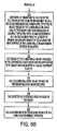
- Figure 6shows a flow chart of a method of operation for the catheter.
- a catheter 100includes a tip assembly 101 and a multi-lumen tube 102 coupled thereto.
- the tip assembly 101comprises a generally prolate spheroid with a long axis 103.
- the tip assembly 101includes a proximal end 109 and a distal end 110, with the proximal end 109 coupled to the multi-lumen tube 102 for coupling control signals, energy and fluids between the tip assembly 101 and a control system (not show).
- the tip assembly 101is disposed in a dilatation 113 of a lumen 104 of the body of a patient with the long axis 103 approximately parallel to lumen walls 105.
- the dilatation 113 in the lumen 104may comprise an aneurysm in a blood vessel.
- the dilatation 113may comprise any sphincter or lumen of the body.
- the tip assembly 101may comprise another shape, such as curved or needle-like disposed for fitting within a particular body cavity, for avoiding a particular body structure, or for adaptation to a particular body structure.
- the tip assembly 101may comprise a curved, needle-like shape adapted to a surface curvature of an eyeball so that the tip assembly 101 can be inserted under an eyelid.
- the catheter tube 102comprises a relatively inert and nonconducting substance such as woven dacron.
- the catheter tube 102may comprise other relatively inert and nonconducting materials such as kevlar, nylon, or plastic, or combinations thereof.
- the tip assembly 101may include one or more marker elements preferably disposed at or near the distal end 110 of the tip assembly 101 and/or at or near the proximal end 109 of the tip assembly 101, which are noticeable using fluoroscopy or ultrasound or other suitable means.
- a radiologist or surgeoncan position the catheter 100 relative to the dilatation 113 without any requirement for a camera or other optical equipment disposed in or near the dilatation 113.
- such a camera or other optical equipmentmay be included.
- the tip assembly 101includes at least one port 111, from which a treatment fluid 112 may flow out of the tip assembly 101 and into or near the dilatation 113, and at least one suction port 114.
- the port 111 and suction port 114are further disposed to comprise a fluid circulation system, wherein at least one port 111 is a fluid outlet port and at least one suction port 114 is a fluid inlet port.
- the fluid circulation systemis disposed for circulating fluid in the region of the dilatation 113 near the catheter 100, such as for delivering fluid for cooling the region and for removing other fluid for aspirating the region.
- the port 111is disposed for delivering substantially equal amounts of treatment fluid 112 in all directions from the tip assembly 101.
- the port 111may be disposed for delivering differing amounts of treatment fluid 112 in an asymmetrical pattern near the tip assembly 101, either by altering the shape of a single port 111 or by including a plurality of ports 111.
- there could be a single port 111alternatively there could be a plurality of ports 111 each substantially the same size but with a variable number of ports 111 located in various locations about the tip assembly 101, and further alternatively there may be ports 111 of substantially different sizes.
- the ports 111are each open at all times, in alternative embodiments, they may be subject to a microscopic mechanical device or other technique for closing some or all of them at selected times.
- the ports 111are also disposed for removing fluids from the lumen 104.
- the ports 111may handle all fluid delivery and removal during treatment, and no suction ports 114 are needed. All of the ports 111 may be coupled to a single lumen in the catheter tube 102, or some ports 111 may be coupled to one lumen and other ports 111 coupled to another lumen in the catheter tube 102.
- movement of treatment fluid 112 through the ports 111is controllable so that, according to the needs of a treatment regimen, at a given time all of the ports 111 may deliver treatment fluid 112, all of the ports 111 may remove treatment fluid 112 and/or other fluids, or some ports 111 may deliver treatment fluid 112 while other ports 111 simultaneously remove treatment fluid 112 and/or other fluids.
- separately controllable suction ports 114coupled to a lumen in the catheter tube 102, may also be located on an exterior surface of the tip assembly 101, and in combination with the ports 111 may comprise a fluid circulation system.
- the tip assembly 101may also include at least one temperature sensor 115 and at least one pressure sensor 116, both preferably disposed at or near the surface of the tip assembly 101.
- the sensorsare coupled using the catheter tube 102 to a control system (not shown) and to an operator presentation device (not shown). The sensors provide signals to the control system for feedback control, and to the operator presentation device for presenting information to an operator.
- the temperature sensor 115comprises a plurality of temperature sensors, such as thermistors or thermocouples, and the control system provides feedback control to maintain various temperatures selected by the operator.
- the operator presentation devicecomprises a temperature reporting gauge.
- the pressure sensor 116comprises a plurality of pressure sensors, and the control system provides feedback control to maintain various pressures selected by the operator.
- the operator presentation devicecomprises a pressure reporting gauge.
- the tip assembly 101may be fitted with other and further equipment.
- equipmentmay include a camera or other light-gathering device, either for aiding a surgeon in manipulating the catheter 100 (e.g., maneuvering the tip assembly 101 to reach the dilatation 113), or for photographically recording the action of the catheter 100 and associated equipment; a laser or other device for ablating or reducing obstructions; or other equipment. Coupling cameras or other light-gathering devices, or lasers or other ablating or reducing devices, to catheters 100 is known in the art of medical devices.
- treatment fluidis used generically to mean and refer to any fluid which can act as an electrolyte.
- the treatment fluid 112is a saline solution.
- the treatment fluid 112may be collagen, a collagenous fluid, or any other fluid which is readily absorbed by the tissue of the lumen walls 104 and which readily absorbs RF energy.
- the treatment fluid 112may comprise medicine, water, or a fluid which is relatively inert and non-bioreactive but heat conductive.
- the tip assembly 101also includes a first occluding balloon 106 preferably disposed at or near a proximal end 109 of the tip assembly 101, and a second occluding balloon 107 preferably disposed at or near the distal end 110 of the tip assembly 101.
- the occluding balloons 106 and 107are disposed so that when inflated, and in combination with the body of the tip assembly 101, they form a gas-tight or fluid-tight seal against the lumen walls 105 and seal off the portion of the dilatation 113 to be treated from other portions of the lumen 104.
- the occluding balloons 106 and 107preferably comprise ring-shaped annular balloons; however, in an alternative embodiment, the distal occluding balloon 107 may comprise a spherical or ellipsoidal balloon disposed at the distal end 110 of the tip assembly 101 in such a manner that when inflated it surrounds the catheter 100 and makes a gas-tight or fluid-tight seal against the lumen walls 104.
- both occluding balloons 106 and 107are coupled to a single lumen in the catheter tube 102 disposed for delivery of an inflation fluid from a source (not shown).
- the occluding balloons 106 and 107are coupled to separate lumina in the catheter tube 102 disposed for delivery of inflation fluid from sources (not shown), so that the occluding balloons 106 and 107 may be inflated independently of each other.
- At least one occluding balloon 106 or 107is disposed to anchor the catheter 100 at a selected location within the lumen 104; alternatively, both occluding balloons 106 and 107 may be to anchor the catheter 100.
- the occluding balloons 106 and 107when inflated prevent the catheter 100 from being expelled from the body in like manner as the operation of a Foley catheter.
- the balloon used to anchor the catheter 100may comprise either occluding balloon 106 or 107, or an additional or alternative balloon which is disposed solely or primarily for the purpose of anchoring the catheter 100 into the selected location, again in like manner as the operation of a Foley catheter.
- the tip assembly 101may also include a third balloon 108 (hereinafter referred to as a "treatment balloon 108"), preferably located intermediately between the occluding balloons 106 and 107, which is inflated using a lumen in the catheter tube 102 for delivery of treatment fluid 112 from a source (not shown) through at least one port 111.
- the treatment balloon 108is disposed so that when inflated its surface physically comes into contact with the tissue of the lumen walls 105 which comprise the dilatation 113.
- the treatment balloon 108may also include a porous, microporous, or semiporous membrane through which the treatment fluid 112 may flow.
- the suction ports 114are preferably located between the outside surface of intermediate treatment balloon 108 and the outside surfaces of the occluding balloons 106 and/or 107, so that the fluid is drawn into the suction ports 114 from the occluded region of the lumen 104.
- the suction ports 114may be used either separately or at the same time that treatment fluid 112 is delivered from the ports 111 into the treatment balloon 108.
- the catheter 110also includes at least one electrode, described in more detail below, preferably disposed on the tip assembly 101 between the occluding balloons 106 and 107.
- the electrodesare coupled using the catheter tube 102 to a power source 120.
- the power source 120provides energy to the electrodes, which emit that energy into the lumen walls 105 of the dilatation 113 which have been perfused with the treatment fluid 112 so as to affect the lumen walls 105 of the dilatation 113.
- Fig. 3shows a first aspect of the preferred embodiment using direct contact bipolar electrodes 123 to emit RF energy for heating, ablation and/or shrinkage of the dilatation 113.
- a plurality of bipolar electrodes 123are distributed more or less equidistant from each other and disposed so that when the treatment balloon 108 is inflated the electrodes 123 are put in direct contact with the inner surface of the lumen walls 105 in the occluded region of the dilatation 113.
- the electrodes 123are disposed on an expandable conductor mesh 122 surrounding around the treatment balloon 108.
- the conductor mesh 122 and electrodes 123may be disposed in or near the surface of the treatment balloon 108.
- Fig. 4shows a second aspect of the preferred embodiment using monopolar ring electrodes 124 to emit RF energy for heating, ablation and shrinkage of the dilatation 113.
- a plurality of monopolar ring electrodes 124are disposed repeatedly on or near the surface of the tip assembly 101 between its proximal end 109 and distal end 110.
- Fig. 5shows a third aspect of the preferred embodiment using bipolar ring electrodes 125 to emit RF energy for heating, ablation and shrinkage of the dilatation 113.
- a plurality of bipolar ring electrodes 125are disposec repeatedly on or near the surface of the tip assembly 101 between the proximal end 109 and the distal end 110 of the tip assembly 101.
- many configurations of electrodes and sensors 116may operate under processor control to achieve such effects.
- distances between pairs of ring electrodes 124may be adjusted, either during manufacture, dynamically before use of the catheter tip 101, or otherwise.
- the sensors 116may be effective to measure other dynamic features of the treatment fluid 112 and lumen-wall tissue of the dilatation 113, such as a localized electrical impedance, a localized fluid flow, or some combination thereof.
- the processormay be effective to control other features ofthe RF energy, such as a pulse shape or duty cycle of a pulse for RF energy delivery, a frequency for RF energy delivery, a time duration for pulses or time duration between pulses, an order for selection of individual ring electrodes 120 for delivery of RF energy, or some combination thereof.
- Electrodesare coupled to a power source 120 using a conductor 121 in the catheter tube 102.
- the conductor 121is preferably insulated so as to avoid electrical coupling with the catheter tube 102, the treatment fluid 112 or the lumen walls 105.
- the power source 120provides energy to the electrodes, which emit that energy into the treatment fluid 112 and tissue of the lumen walls 105 in the occluded region of the dilatation 113.
- RF energyis used generically to mean and refer to any means for heating the treatment fluid 112 and/or tissue of the lumen walls 105, broadly including the application of RF energy in a wide range of frequencies, such as the 300 to 700 MHz frequency described herein as well as other microwave frequencies and other frequencies. Those skilled in the art would recognize, after perusal of this application, that other means for heating the treatment fluid 112 and lumen walls 105 may be applied.
- the means for heatingmay comprise light.
- the lightmay be delivered by a laser, light-emitting diode, or other light source coupled to the tip assembly 101.
- the energy source 120is preferably located outside the lumen 104 and outside the body.
- the RF energy source 120generates a continuous or pulsed waveform, preferably a sinusoidal waveform or a square waveform, such as an RF energy generator available as a standard product from Radionics Valley Laboratories, a division of Pfizer, Inc.
- the RF energy source 120supplies about 50 watts of power, distributed to all of the electrodes 123 collectively, and pulsed in a round-robin fashion among the electrodes 123 so as to equally distribute the delivered energy to all positions along the tip assembly 101.
- the RF energy source 120may comprise a processor which is responsive to signals from the sensors 116 and to a computed or expected amount of the treatment fluid 112 and lumen wall tissue 105 to be treated.
- the processorcomputes an effective amount of time and RF energy to deliver to each individual electrode, and controls delivery of RF energy to each individual electrode so as to deliver RF energy to localized points of the treatment fluid 112 and lumen wall tissues 105 which have absorbed it.
- Figure 6shows a flowchart for a method of operation of the catheter 100.
- a method 200 of operation for the catheter 100comprises a sequence of steps between the flow points 201 and 220.
- the method 200is carried out using the catheter 100, as well as other and further equipment which would be clearly deemed necessary or desirable by those skilled in the art.
- the catheter 100is ready for use to treat dilatation 113.
- the catheter 100is inserted into the lumen 104 of a patient at a natural body orifice such as the mouth, anus or urethra.
- the catheter 100may be inserted into a blood vessel near a body surface, such as the jugular vein or carotid artery or other blood vessel in the neck, or may be inserted into the patient at a body structure which is made available during surgery or by virtue of a wound; the body structure may comprise a blood vessel, tubular organ, the lymphatic system, a sinus cavity or other ear/nose/throat structure, the intestines, the urethra, a mass of tissue such as a cyst or a fatty deposit, or some other body structure.
- the catheter 100is maneuvered by an operator (not shown) to a position in the lumen 104 approximately adjacent to the dilatation 113 while the operator views the position of the catheter 100 using fluoroscopy, ultrasound, or other suitable means.
- the occluding balloons 106 and 107are inflated and the dilatation 113 sealed off from the remainder of the lumen 104.
- the treatment balloon 108is inflated with treatment fluid 112 exuded from ports 11I while simultaneously any body fluids in the occluded dilatation 113 are removed by suctioning them into suction ports 114 disposed on the tip assembly 101 between the occluding balloons 106 and 107 and coupled to a suction lumen in the catheter tube 102. Body fluids are thus removed from the occluded portion of the dilatation 113 by the dual action of suction outside the treatment balloon 108 and pressure within it.
- RF energyis emitted by electrodes in the catheter tip assembly 101 at a selected frequency and power level effective to heat the treatment fluid 112 to a temperature at which it is readily absorbable into the tissue of the lumen walls 105.
- the treatment fluid 112 in the treatment balloon 108is pressurized to a selected pressure, effective to cause the treatment fluid 112 to exude through the microporous membrane of the treatment balloon and come into contact with the lumen walls 105.
- the heated treatment fluid 112is suffused into and absorbed by the tissues of the lumen walls 105.
- additional RF energyis emitted by the electrodes in the catheter tip assembly 101 at a selected frequency and power level effective to preferentially heat tissues of the lumen walls 105 which have absorbed the treatment fluid 112.
- cool treatment fluid 112may be circulated in the occluded portion of the lumen 104 by exuding it from ports 111 and suctioning it into suction ports 114, in order to minimize heating and damage of cells lining the inner surface of the lumen walls 105. Heating of lumen wall tissues 105 continues until they have been softened.
- the heated treatment fluid 112is removed from the occluded portion of the dilatation 113 via the suction ports 114 and the occluded portion of the dilatation is filled with chilled treatment fluid 112 via the ports 111.
- the dilatation 113is contracted by application of the chilled treatment fluid 112 and by application of a vacuum via the suction ports 114 so that dilatation 113 shrinks to a diameter within a normal diameter range for the lumen 104.
- additional RF energymay be emitted by the electrodes in the catheter tip assembly 101 at a selected frequency and power level effective to ablate tissues of the lumen walls 105, while chilled treatment fluid 112 is circulated by exuding it in via the ports 111 and suctioning it out via the suction ports 114 in order to minimize heating and damage of cells lining the inner surface of the lumen walls 105 and remove detritus of ablation.
- the tissues of the lumen walls 105are hardened in the contracted condition by further application of RF energy and circulation of chilled treatment fluid 112.
- the occluding balloons 106 and 107 and the treatment balloon 108are deflated.
- the catheter 100is removed from the body of the patient.
- the dilatationhas been treated and should be in a condition for normal operation.
Landscapes
- Health & Medical Sciences (AREA)
- Life Sciences & Earth Sciences (AREA)
- Heart & Thoracic Surgery (AREA)
- Animal Behavior & Ethology (AREA)
- Public Health (AREA)
- Pulmonology (AREA)
- Engineering & Computer Science (AREA)
- Anesthesiology (AREA)
- Biomedical Technology (AREA)
- Hematology (AREA)
- Child & Adolescent Psychology (AREA)
- General Health & Medical Sciences (AREA)
- Biophysics (AREA)
- Veterinary Medicine (AREA)
- Media Introduction/Drainage Providing Device (AREA)
- Surgical Instruments (AREA)
- Mechanical Treatment Of Semiconductor (AREA)
- Lasers (AREA)
- Electrotherapy Devices (AREA)
- Radiation-Therapy Devices (AREA)
- Thermotherapy And Cooling Therapy Devices (AREA)
- Laser Surgery Devices (AREA)
- Materials For Medical Uses (AREA)
Abstract
Description
Claims (16)
- A catheter for use in treating a dilatation of a body and being insertableinto a localised region of said body, said catheter comprising:a port (111) through which a substance (112) capable of perfusing into atleast some tissue in said localised region may be exuded; andmeans for emitting energy of a frequency and in an amount effective tocause a temperature change in said substance.
- A catheter according to claim 1 wherein said means for emitting energycomprises direct contact bipolar electrodes (123) to emit RF energy.
- A catheter according to claim 2 comprising a plurality of bipolar electrodes(123) distributed substantially equidistant from each other on said cathode.
- A catheter according to claim 1 wherein said means for emitting energycomprise a plurality of monopolar ring electrodes (124).
- A catheter according to claim 1 wherein said means for emitting energycomprise a plurality of bipolar ring electrodes (125).
- A catheter according to any one of the preceding claims further comprisinga first occluding balloon (106) disposed at or near a proximal end of a tip part ofsaid catheter and a second occluding balloon (107) disposed at or near the distalend of said tip part of said catheter, said occluding balloons being inflatable toform gas-tight or fluid-tight seals against walls of a part of the body into which thecatheter has been inserted.
- A catheter according to claim 6 wherein said occluding balloons comprisering-shaped annular balloons.
- A catheter according to claim 6 wherein said second occluding balloon(107) comprises a spherical or ellipsoidal balloon.
- A catheter according to any one of the preceding claims further comprisinga treatment balloon (108) and wherein said port opens into said treatment balloon(108).
- A catheter according to claim 9 wherein said treatment balloon includes aporous, microporous or semiporous membrane through which said substance (112)may flow.
- A catheter according to claim 9 or 10 wherein said means for emittingenergy comprise bipolar electrodes disposed on an expandible conductor mesh(112) surrounding said treatment balloon (108).
- A catheter according to any one of the preceding claims further comprisinga power source coupled to said means for emitting energy.
- A catheter according to claim 12 wherein said power source is adapted toprovide RF energy at a frequency in the range of from 300 to 700 MHz.
- A catheter according to claim 12 or 13 wherein said energy source isadapted to provide about 50 W of power.
- A catheter according to any one of the preceding claims further comprisinga source of said substance, said substance being selected from the groupcomprising: electrolyte; saline solution; collagen; a collagenous fluid; medicine;non-toxic foam; and water.
- A catheter according to any one of the preceding claims further comprisinga sensor for measurement of pH, pressure or temperature.
Applications Claiming Priority (3)
| Application Number | Priority Date | Filing Date | Title |
|---|---|---|---|
| US490622 | 1983-05-02 | ||
| US09/490,622US7184827B1 (en) | 2000-01-24 | 2000-01-24 | Shrinkage of dilatations in the body |
| EP01902144AEP1250170A1 (en) | 2000-01-24 | 2001-01-24 | Shrinkage of dilatations in the body |
Related Parent Applications (1)
| Application Number | Title | Priority Date | Filing Date |
|---|---|---|---|
| EP01902144ADivisionEP1250170A1 (en) | 2000-01-24 | 2001-01-24 | Shrinkage of dilatations in the body |
Publications (3)
| Publication Number | Publication Date |
|---|---|
| EP1264613A2true EP1264613A2 (en) | 2002-12-11 |
| EP1264613A3 EP1264613A3 (en) | 2004-01-28 |
| EP1264613B1 EP1264613B1 (en) | 2007-02-21 |
Family
ID=23948829
Family Applications (2)
| Application Number | Title | Priority Date | Filing Date |
|---|---|---|---|
| EP01902144AWithdrawnEP1250170A1 (en) | 2000-01-24 | 2001-01-24 | Shrinkage of dilatations in the body |
| EP02020629AExpired - LifetimeEP1264613B1 (en) | 2000-01-24 | 2001-01-24 | Catheter for shrinkage of dilations in the body |
Family Applications Before (1)
| Application Number | Title | Priority Date | Filing Date |
|---|---|---|---|
| EP01902144AWithdrawnEP1250170A1 (en) | 2000-01-24 | 2001-01-24 | Shrinkage of dilatations in the body |
Country Status (8)
| Country | Link |
|---|---|
| US (1) | US7184827B1 (en) |
| EP (2) | EP1250170A1 (en) |
| JP (1) | JP2004500184A (en) |
| AT (1) | ATE354397T1 (en) |
| AU (1) | AU2001227975A1 (en) |
| CA (1) | CA2390800A1 (en) |
| DE (1) | DE60126748T2 (en) |
| WO (1) | WO2001052930A1 (en) |
Cited By (16)
| Publication number | Priority date | Publication date | Assignee | Title |
|---|---|---|---|---|
| US8364237B2 (en) | 2005-03-28 | 2013-01-29 | Vessix Vascular, Inc. | Tuned RF energy for selective treatment of atheroma and other target tissues and/or structures |
| US8396548B2 (en) | 2008-11-14 | 2013-03-12 | Vessix Vascular, Inc. | Selective drug delivery in a lumen |
| US8401667B2 (en) | 2008-11-17 | 2013-03-19 | Vessix Vascular, Inc. | Selective accumulation of energy with or without knowledge of tissue topography |
| US8496653B2 (en) | 2007-04-23 | 2013-07-30 | Boston Scientific Scimed, Inc. | Thrombus removal |
| US8551096B2 (en) | 2009-05-13 | 2013-10-08 | Boston Scientific Scimed, Inc. | Directional delivery of energy and bioactives |
| US8920414B2 (en) | 2004-09-10 | 2014-12-30 | Vessix Vascular, Inc. | Tuned RF energy and electrical tissue characterization for selective treatment of target tissues |
| US9125667B2 (en) | 2004-09-10 | 2015-09-08 | Vessix Vascular, Inc. | System for inducing desirable temperature effects on body tissue |
| US9125666B2 (en) | 2003-09-12 | 2015-09-08 | Vessix Vascular, Inc. | Selectable eccentric remodeling and/or ablation of atherosclerotic material |
| US9277955B2 (en) | 2010-04-09 | 2016-03-08 | Vessix Vascular, Inc. | Power generating and control apparatus for the treatment of tissue |
| WO2016130098A1 (en)* | 2015-02-10 | 2016-08-18 | Ozturk Kayhan | Transesophageal thermal tactile stimulation apparatus |
| WO2017064134A1 (en)* | 2015-10-12 | 2017-04-20 | Acandis Gmbh & Co. Kg | Balloon catheter for endovascular temperature control |
| US9757193B2 (en) | 2002-04-08 | 2017-09-12 | Medtronic Ardian Luxembourg S.A.R.L. | Balloon catheter apparatus for renal neuromodulation |
| US9827040B2 (en) | 2002-04-08 | 2017-11-28 | Medtronic Adrian Luxembourg S.a.r.l. | Methods and apparatus for intravascularly-induced neuromodulation |
| US9919144B2 (en) | 2011-04-08 | 2018-03-20 | Medtronic Adrian Luxembourg S.a.r.l. | Iontophoresis drug delivery system and method for denervation of the renal sympathetic nerve and iontophoretic drug delivery |
| US9974607B2 (en) | 2006-10-18 | 2018-05-22 | Vessix Vascular, Inc. | Inducing desirable temperature effects on body tissue |
| US10709490B2 (en) | 2014-05-07 | 2020-07-14 | Medtronic Ardian Luxembourg S.A.R.L. | Catheter assemblies comprising a direct heating element for renal neuromodulation and associated systems and methods |
Families Citing this family (167)
| Publication number | Priority date | Publication date | Assignee | Title |
|---|---|---|---|---|
| US8353908B2 (en) | 1996-09-20 | 2013-01-15 | Novasys Medical, Inc. | Treatment of tissue in sphincters, sinuses, and orifices |
| US9023031B2 (en)* | 1997-08-13 | 2015-05-05 | Verathon Inc. | Noninvasive devices, methods, and systems for modifying tissues |
| US20100114087A1 (en)* | 1998-02-19 | 2010-05-06 | Edwards Stuart D | Methods and devices for treating urinary incontinence |
| US7229469B1 (en) | 1999-10-02 | 2007-06-12 | Quantumcor, Inc. | Methods for treating and repairing mitral valve annulus |
| US20040215235A1 (en) | 1999-11-16 | 2004-10-28 | Barrx, Inc. | Methods and systems for determining physiologic characteristics for treatment of the esophagus |
| WO2001035846A1 (en)* | 1999-11-16 | 2001-05-25 | Ganz Robert A | System and method of treating abnormal tissue in the human esophagus |
| US7306591B2 (en) | 2000-10-02 | 2007-12-11 | Novasys Medical, Inc. | Apparatus and methods for treating female urinary incontinence |
| DE10105592A1 (en) | 2001-02-06 | 2002-08-08 | Achim Goepferich | Placeholder for drug release in the frontal sinus |
| US7653438B2 (en) | 2002-04-08 | 2010-01-26 | Ardian, Inc. | Methods and apparatus for renal neuromodulation |
| US8317816B2 (en) | 2002-09-30 | 2012-11-27 | Acclarent, Inc. | Balloon catheters and methods for treating paranasal sinuses |
| US7064187B2 (en) | 2002-11-26 | 2006-06-20 | Crosscart, Inc. | Substantially non-immunogenic injectable collagen |
| US7410480B2 (en) | 2004-04-21 | 2008-08-12 | Acclarent, Inc. | Devices and methods for delivering therapeutic substances for the treatment of sinusitis and other disorders |
| US9101384B2 (en) | 2004-04-21 | 2015-08-11 | Acclarent, Inc. | Devices, systems and methods for diagnosing and treating sinusitis and other disorders of the ears, Nose and/or throat |
| US20070208252A1 (en) | 2004-04-21 | 2007-09-06 | Acclarent, Inc. | Systems and methods for performing image guided procedures within the ear, nose, throat and paranasal sinuses |
| US7361168B2 (en) | 2004-04-21 | 2008-04-22 | Acclarent, Inc. | Implantable device and methods for delivering drugs and other substances to treat sinusitis and other disorders |
| US9399121B2 (en) | 2004-04-21 | 2016-07-26 | Acclarent, Inc. | Systems and methods for transnasal dilation of passageways in the ear, nose or throat |
| US20190314620A1 (en) | 2004-04-21 | 2019-10-17 | Acclarent, Inc. | Apparatus and methods for dilating and modifying ostia of paranasal sinuses and other intranasal or paranasal structures |
| US8764729B2 (en) | 2004-04-21 | 2014-07-01 | Acclarent, Inc. | Frontal sinus spacer |
| US9351750B2 (en) | 2004-04-21 | 2016-05-31 | Acclarent, Inc. | Devices and methods for treating maxillary sinus disease |
| US20060004323A1 (en) | 2004-04-21 | 2006-01-05 | Exploramed Nc1, Inc. | Apparatus and methods for dilating and modifying ostia of paranasal sinuses and other intranasal or paranasal structures |
| US8747389B2 (en) | 2004-04-21 | 2014-06-10 | Acclarent, Inc. | Systems for treating disorders of the ear, nose and throat |
| US7419497B2 (en) | 2004-04-21 | 2008-09-02 | Acclarent, Inc. | Methods for treating ethmoid disease |
| US8146400B2 (en) | 2004-04-21 | 2012-04-03 | Acclarent, Inc. | Endoscopic methods and devices for transnasal procedures |
| US8864787B2 (en) | 2004-04-21 | 2014-10-21 | Acclarent, Inc. | Ethmoidotomy system and implantable spacer devices having therapeutic substance delivery capability for treatment of paranasal sinusitis |
| US7654997B2 (en) | 2004-04-21 | 2010-02-02 | Acclarent, Inc. | Devices, systems and methods for diagnosing and treating sinusitus and other disorders of the ears, nose and/or throat |
| US8932276B1 (en) | 2004-04-21 | 2015-01-13 | Acclarent, Inc. | Shapeable guide catheters and related methods |
| US9089258B2 (en) | 2004-04-21 | 2015-07-28 | Acclarent, Inc. | Endoscopic methods and devices for transnasal procedures |
| US7462175B2 (en) | 2004-04-21 | 2008-12-09 | Acclarent, Inc. | Devices, systems and methods for treating disorders of the ear, nose and throat |
| US7803150B2 (en) | 2004-04-21 | 2010-09-28 | Acclarent, Inc. | Devices, systems and methods useable for treating sinusitis |
| US7559925B2 (en) | 2006-09-15 | 2009-07-14 | Acclarent Inc. | Methods and devices for facilitating visualization in a surgical environment |
| US9554691B2 (en) | 2004-04-21 | 2017-01-31 | Acclarent, Inc. | Endoscopic methods and devices for transnasal procedures |
| US8894614B2 (en) | 2004-04-21 | 2014-11-25 | Acclarent, Inc. | Devices, systems and methods useable for treating frontal sinusitis |
| US20060063973A1 (en) | 2004-04-21 | 2006-03-23 | Acclarent, Inc. | Methods and apparatus for treating disorders of the ear, nose and throat |
| US20070167682A1 (en) | 2004-04-21 | 2007-07-19 | Acclarent, Inc. | Endoscopic methods and devices for transnasal procedures |
| US8702626B1 (en) | 2004-04-21 | 2014-04-22 | Acclarent, Inc. | Guidewires for performing image guided procedures |
| US10188413B1 (en) | 2004-04-21 | 2019-01-29 | Acclarent, Inc. | Deflectable guide catheters and related methods |
| WO2006031541A1 (en)* | 2004-09-09 | 2006-03-23 | Vnus Medical Technologies, Inc. | Methods and apparatus for treatment of hollow anatomical structures |
| US9713730B2 (en) | 2004-09-10 | 2017-07-25 | Boston Scientific Scimed, Inc. | Apparatus and method for treatment of in-stent restenosis |
| US8951225B2 (en) | 2005-06-10 | 2015-02-10 | Acclarent, Inc. | Catheters with non-removable guide members useable for treatment of sinusitis |
| US8114113B2 (en) | 2005-09-23 | 2012-02-14 | Acclarent, Inc. | Multi-conduit balloon catheter |
| US8019435B2 (en) | 2006-05-02 | 2011-09-13 | Boston Scientific Scimed, Inc. | Control of arterial smooth muscle tone |
| US8190389B2 (en) | 2006-05-17 | 2012-05-29 | Acclarent, Inc. | Adapter for attaching electromagnetic image guidance components to a medical device |
| US9820688B2 (en) | 2006-09-15 | 2017-11-21 | Acclarent, Inc. | Sinus illumination lightwire device |
| US8439687B1 (en) | 2006-12-29 | 2013-05-14 | Acclarent, Inc. | Apparatus and method for simulated insertion and positioning of guidewares and other interventional devices |
| US10463886B2 (en) | 2007-02-22 | 2019-11-05 | Ramot At Tel-Aviv University Ltd. | Treating weakened vessel wall such as vulnerable plaque or aneurysms |
| US8118757B2 (en) | 2007-04-30 | 2012-02-21 | Acclarent, Inc. | Methods and devices for ostium measurement |
| US8641711B2 (en) | 2007-05-04 | 2014-02-04 | Covidien Lp | Method and apparatus for gastrointestinal tract ablation for treatment of obesity |
| US8485199B2 (en) | 2007-05-08 | 2013-07-16 | Acclarent, Inc. | Methods and devices for protecting nasal turbinate during surgery |
| US20090012518A1 (en)* | 2007-07-06 | 2009-01-08 | Utley David S | Method and Apparatus for Ablation of Benign, Pre-Cancerous and Early Cancerous Lesions That Originate Within the Epithelium and are Limited to the Mucosal Layer of the Gastrointestinal Tract |
| WO2009009443A1 (en) | 2007-07-06 | 2009-01-15 | Barrx Medical, Inc. | Method and apparatus for gastrointestinal tract ablation to achieve loss of persistent and/or recurrent excess body weight following a weight-loss operation |
| CN102688092B (en)* | 2007-07-06 | 2015-04-22 | 柯惠有限合伙公司 | Ablation in the gastrointestinal tract to achieve hemostasis and eradicate lesions with a propensity for bleeding |
| US20090054922A1 (en)* | 2007-08-23 | 2009-02-26 | Broker Harshal S | Apparatus and Method for the Intravascular Control of Trauma |
| US20100198191A1 (en)* | 2007-12-20 | 2010-08-05 | Acclarent, Inc. | Method and system for treating target tissue within the eustachian tube |
| US10206821B2 (en) | 2007-12-20 | 2019-02-19 | Acclarent, Inc. | Eustachian tube dilation balloon with ventilation path |
| US8182432B2 (en) | 2008-03-10 | 2012-05-22 | Acclarent, Inc. | Corewire design and construction for medical devices |
| RU2500337C2 (en) | 2008-07-30 | 2013-12-10 | Аккларент, Инк. | Device and methods of identifying orifice of paranasal sinus |
| DE102008045038A1 (en)* | 2008-08-29 | 2010-03-04 | Osypka, Peter, Dr.- Ing. | Device for ablating the mouth of the pulmonary veins |
| BRPI0919195A2 (en) | 2008-09-18 | 2019-09-24 | Acclarent Inc | Methods and Apparatus for the Treatment of Ear, Nose, and Throat Disorders |
| US20100241155A1 (en) | 2009-03-20 | 2010-09-23 | Acclarent, Inc. | Guide system with suction |
| US7978742B1 (en) | 2010-03-24 | 2011-07-12 | Corning Incorporated | Methods for operating diode lasers |
| US8435290B2 (en) | 2009-03-31 | 2013-05-07 | Acclarent, Inc. | System and method for treatment of non-ventilating middle ear by providing a gas pathway through the nasopharynx |
| US20100312338A1 (en)* | 2009-06-05 | 2010-12-09 | Entrigue Surgical, Inc. | Systems, devices and methods for providing therapy to an anatomical structure |
| CA2788082C (en) | 2010-01-28 | 2018-02-20 | Art Healthcare Ltd. | Method and device of detecting and/or blocking reflux |
| US9192790B2 (en) | 2010-04-14 | 2015-11-24 | Boston Scientific Scimed, Inc. | Focused ultrasonic renal denervation |
| US8473067B2 (en) | 2010-06-11 | 2013-06-25 | Boston Scientific Scimed, Inc. | Renal denervation and stimulation employing wireless vascular energy transfer arrangement |
| US9358365B2 (en) | 2010-07-30 | 2016-06-07 | Boston Scientific Scimed, Inc. | Precision electrode movement control for renal nerve ablation |
| US9155589B2 (en) | 2010-07-30 | 2015-10-13 | Boston Scientific Scimed, Inc. | Sequential activation RF electrode set for renal nerve ablation |
| US9084609B2 (en) | 2010-07-30 | 2015-07-21 | Boston Scientific Scime, Inc. | Spiral balloon catheter for renal nerve ablation |
| US9463062B2 (en) | 2010-07-30 | 2016-10-11 | Boston Scientific Scimed, Inc. | Cooled conductive balloon RF catheter for renal nerve ablation |
| US9408661B2 (en) | 2010-07-30 | 2016-08-09 | Patrick A. Haverkost | RF electrodes on multiple flexible wires for renal nerve ablation |
| US10744307B2 (en) | 2010-09-23 | 2020-08-18 | Best Medical International, Inc. | Multi-purpose balloon catheter for intra cavity radiation delivery |
| US10589071B2 (en) | 2010-09-23 | 2020-03-17 | Best Medical International, Inc. | Multiple function balloon catheter |
| US9155492B2 (en) | 2010-09-24 | 2015-10-13 | Acclarent, Inc. | Sinus illumination lightwire device |
| US8974451B2 (en) | 2010-10-25 | 2015-03-10 | Boston Scientific Scimed, Inc. | Renal nerve ablation using conductive fluid jet and RF energy |
| US9220558B2 (en) | 2010-10-27 | 2015-12-29 | Boston Scientific Scimed, Inc. | RF renal denervation catheter with multiple independent electrodes |
| US9028485B2 (en) | 2010-11-15 | 2015-05-12 | Boston Scientific Scimed, Inc. | Self-expanding cooling electrode for renal nerve ablation |
| US9089350B2 (en) | 2010-11-16 | 2015-07-28 | Boston Scientific Scimed, Inc. | Renal denervation catheter with RF electrode and integral contrast dye injection arrangement |
| US9668811B2 (en) | 2010-11-16 | 2017-06-06 | Boston Scientific Scimed, Inc. | Minimally invasive access for renal nerve ablation |
| US9326751B2 (en) | 2010-11-17 | 2016-05-03 | Boston Scientific Scimed, Inc. | Catheter guidance of external energy for renal denervation |
| US9060761B2 (en) | 2010-11-18 | 2015-06-23 | Boston Scientific Scime, Inc. | Catheter-focused magnetic field induced renal nerve ablation |
| US9192435B2 (en) | 2010-11-22 | 2015-11-24 | Boston Scientific Scimed, Inc. | Renal denervation catheter with cooled RF electrode |
| US9023034B2 (en) | 2010-11-22 | 2015-05-05 | Boston Scientific Scimed, Inc. | Renal ablation electrode with force-activatable conduction apparatus |
| US20120157993A1 (en) | 2010-12-15 | 2012-06-21 | Jenson Mark L | Bipolar Off-Wall Electrode Device for Renal Nerve Ablation |
| US9220561B2 (en) | 2011-01-19 | 2015-12-29 | Boston Scientific Scimed, Inc. | Guide-compatible large-electrode catheter for renal nerve ablation with reduced arterial injury |
| EP2665433B1 (en) | 2011-01-19 | 2021-03-10 | Fractyl Laboratories Inc. | Devices for the treatment of tissue |
| WO2012148969A2 (en) | 2011-04-25 | 2012-11-01 | Brian Kelly | Apparatus and methods related to constrained deployment of cryogenic balloons for limited cryogenic ablation of vessel walls |
| CN103813745B (en) | 2011-07-20 | 2016-06-29 | 波士顿科学西美德公司 | In order to visualize, be directed at and to melt transcutaneous device and the method for nerve |
| EP2734264B1 (en) | 2011-07-22 | 2018-11-21 | Boston Scientific Scimed, Inc. | Nerve modulation system with a nerve modulation element positionable in a helical guide |
| WO2013055826A1 (en) | 2011-10-10 | 2013-04-18 | Boston Scientific Scimed, Inc. | Medical devices including ablation electrodes |
| EP2765940B1 (en) | 2011-10-11 | 2015-08-26 | Boston Scientific Scimed, Inc. | Off-wall electrode device for nerve modulation |
| US9420955B2 (en) | 2011-10-11 | 2016-08-23 | Boston Scientific Scimed, Inc. | Intravascular temperature monitoring system and method |
| US9364284B2 (en) | 2011-10-12 | 2016-06-14 | Boston Scientific Scimed, Inc. | Method of making an off-wall spacer cage |
| US9162046B2 (en) | 2011-10-18 | 2015-10-20 | Boston Scientific Scimed, Inc. | Deflectable medical devices |
| EP2768568B1 (en) | 2011-10-18 | 2020-05-06 | Boston Scientific Scimed, Inc. | Integrated crossing balloon catheter |
| US8951251B2 (en) | 2011-11-08 | 2015-02-10 | Boston Scientific Scimed, Inc. | Ostial renal nerve ablation |
| WO2013074813A1 (en) | 2011-11-15 | 2013-05-23 | Boston Scientific Scimed, Inc. | Device and methods for renal nerve modulation monitoring |
| US9119632B2 (en) | 2011-11-21 | 2015-09-01 | Boston Scientific Scimed, Inc. | Deflectable renal nerve ablation catheter |
| US20140309550A1 (en)* | 2011-11-28 | 2014-10-16 | Remendium Labs Llc | Treatment of urinary incontinence |
| US9265969B2 (en) | 2011-12-21 | 2016-02-23 | Cardiac Pacemakers, Inc. | Methods for modulating cell function |
| US9028472B2 (en) | 2011-12-23 | 2015-05-12 | Vessix Vascular, Inc. | Methods and apparatuses for remodeling tissue of or adjacent to a body passage |
| EP2797534A1 (en) | 2011-12-28 | 2014-11-05 | Boston Scientific Scimed, Inc. | Device and methods for nerve modulation using a novel ablation catheter with polymeric ablative elements |
| US9050106B2 (en) | 2011-12-29 | 2015-06-09 | Boston Scientific Scimed, Inc. | Off-wall electrode device and methods for nerve modulation |
| CA2865567C (en) | 2012-02-27 | 2022-10-11 | Fractyl Laboratories, Inc. | Heat ablation systems, devices and methods for the treatment of tissue |
| CN103301562B (en) | 2012-03-08 | 2015-08-26 | 财团法人工业技术研究院 | Enzyme treatment method, enzyme treatment apparatus used for the method, and kit comprising the apparatus |
| US8403927B1 (en) | 2012-04-05 | 2013-03-26 | William Bruce Shingleton | Vasectomy devices and methods |
| EP3711810B1 (en) | 2012-04-19 | 2023-02-22 | Fractyl Health, Inc. | Tissue expansion systems |
| US10660703B2 (en) | 2012-05-08 | 2020-05-26 | Boston Scientific Scimed, Inc. | Renal nerve modulation devices |
| EP3714826A1 (en) | 2012-07-30 | 2020-09-30 | Fractyl Laboratories, Inc. | Electrical energy ablation systems and devices for the treatment of tissue |
| WO2014026055A1 (en) | 2012-08-09 | 2014-02-13 | Fractyl Laboratories Inc. | Ablation systems, devices and methods for the treatment of tissue |
| US10321946B2 (en) | 2012-08-24 | 2019-06-18 | Boston Scientific Scimed, Inc. | Renal nerve modulation devices with weeping RF ablation balloons |
| CN104780859B (en) | 2012-09-17 | 2017-07-25 | 波士顿科学西美德公司 | Self-positioning electrode systems and methods for renal neuromodulation |
| US10549127B2 (en) | 2012-09-21 | 2020-02-04 | Boston Scientific Scimed, Inc. | Self-cooling ultrasound ablation catheter |
| US10398464B2 (en) | 2012-09-21 | 2019-09-03 | Boston Scientific Scimed, Inc. | System for nerve modulation and innocuous thermal gradient nerve block |
| US20140088584A1 (en)* | 2012-09-26 | 2014-03-27 | Boston Scientific Scimed, Inc. | Medical device balloon catheter |
| EP2903626A4 (en) | 2012-10-05 | 2016-10-19 | Fractyl Lab Inc | METHODS, SYSTEMS AND DEVICES FOR REALIZING MULTIPLE TREATMENTS ON A PATIENT |
| CN104869930B (en) | 2012-10-10 | 2020-12-25 | 波士顿科学国际有限公司 | Renal neuromodulation apparatus and methods |
| WO2014163987A1 (en) | 2013-03-11 | 2014-10-09 | Boston Scientific Scimed, Inc. | Medical devices for modulating nerves |
| WO2014143571A1 (en) | 2013-03-11 | 2014-09-18 | Boston Scientific Scimed, Inc. | Medical devices for modulating nerves |
| US9808311B2 (en) | 2013-03-13 | 2017-11-07 | Boston Scientific Scimed, Inc. | Deflectable medical devices |
| US10265122B2 (en) | 2013-03-15 | 2019-04-23 | Boston Scientific Scimed, Inc. | Nerve ablation devices and related methods of use |
| CN105228546B (en) | 2013-03-15 | 2017-11-14 | 波士顿科学国际有限公司 | Medical devices and methods for treating hypertension utilizing impedance compensation |
| EP2967734B1 (en) | 2013-03-15 | 2019-05-15 | Boston Scientific Scimed, Inc. | Methods and apparatuses for remodeling tissue of or adjacent to a body passage |
| US9629684B2 (en) | 2013-03-15 | 2017-04-25 | Acclarent, Inc. | Apparatus and method for treatment of ethmoid sinusitis |
| US9433437B2 (en) | 2013-03-15 | 2016-09-06 | Acclarent, Inc. | Apparatus and method for treatment of ethmoid sinusitis |
| EP3744391B1 (en) | 2013-04-30 | 2023-03-01 | Alcon Inc. | Systems for the treatment of eye conditions |
| US9763827B2 (en) | 2013-04-30 | 2017-09-19 | Tear Film Innovations, Inc. | Systems and methods for the treatment of eye conditions |
| EP3003461B1 (en) | 2013-06-04 | 2019-05-01 | Fractyl Laboratories, Inc. | Systems and devices for reducing the luminal surface area of the gastrointestinal tract |
| CN105473091B (en) | 2013-06-21 | 2020-01-21 | 波士顿科学国际有限公司 | Renal denervation balloon catheter with co-movable electrode supports |
| CN105473092B (en) | 2013-06-21 | 2019-05-17 | 波士顿科学国际有限公司 | The medical instrument for renal nerve ablation with rotatable shaft |
| US9707036B2 (en) | 2013-06-25 | 2017-07-18 | Boston Scientific Scimed, Inc. | Devices and methods for nerve modulation using localized indifferent electrodes |
| CN105358084B (en) | 2013-07-01 | 2018-11-09 | 波士顿科学国际有限公司 | Medical instrument for renal nerve ablation |
| US10413357B2 (en) | 2013-07-11 | 2019-09-17 | Boston Scientific Scimed, Inc. | Medical device with stretchable electrode assemblies |
| CN105377169B (en) | 2013-07-11 | 2019-04-19 | 波士顿科学国际有限公司 | Devices and methods for neuromodulation |
| US9925001B2 (en) | 2013-07-19 | 2018-03-27 | Boston Scientific Scimed, Inc. | Spiral bipolar electrode renal denervation balloon |
| US10342609B2 (en) | 2013-07-22 | 2019-07-09 | Boston Scientific Scimed, Inc. | Medical devices for renal nerve ablation |
| US10695124B2 (en) | 2013-07-22 | 2020-06-30 | Boston Scientific Scimed, Inc. | Renal nerve ablation catheter having twist balloon |
| CN105473093B (en) | 2013-08-22 | 2019-02-05 | 波士顿科学国际有限公司 | Flexible circuit with improved adhesion to renal neuromodulation balloon |
| US9895194B2 (en) | 2013-09-04 | 2018-02-20 | Boston Scientific Scimed, Inc. | Radio frequency (RF) balloon catheter having flushing and cooling capability |
| EP3043732B1 (en) | 2013-09-12 | 2021-04-07 | Fractyl Laboratories, Inc. | Systems and devices for treatment of target tissue |
| EP3043733A1 (en) | 2013-09-13 | 2016-07-20 | Boston Scientific Scimed, Inc. | Ablation balloon with vapor deposited cover layer |
| AT514060B1 (en)* | 2013-10-03 | 2014-10-15 | Ami Agency Medical Innovations Gmbh | Device for the treatment of intraluminal injuries to the gastrointestinal tract |
| US11246654B2 (en) | 2013-10-14 | 2022-02-15 | Boston Scientific Scimed, Inc. | Flexible renal nerve ablation devices and related methods of use and manufacture |
| EP3057488B1 (en) | 2013-10-14 | 2018-05-16 | Boston Scientific Scimed, Inc. | High resolution cardiac mapping electrode array catheter |
| US9770606B2 (en) | 2013-10-15 | 2017-09-26 | Boston Scientific Scimed, Inc. | Ultrasound ablation catheter with cooling infusion and centering basket |
| US9962223B2 (en) | 2013-10-15 | 2018-05-08 | Boston Scientific Scimed, Inc. | Medical device balloon |
| EP3057521B1 (en) | 2013-10-18 | 2020-03-25 | Boston Scientific Scimed, Inc. | Balloon catheters with flexible conducting wires |
| CN105658163B (en) | 2013-10-25 | 2020-08-18 | 波士顿科学国际有限公司 | Embedded thermocouple in denervation flexible circuit |
| KR102284469B1 (en) | 2013-11-22 | 2021-08-02 | 프랙틸 헬쓰, 인코포레이티드 | Systems, devices and methods for the creation of a therapeutic restriction in the gastrointestinal tract |
| EP3091922B1 (en) | 2014-01-06 | 2018-10-17 | Boston Scientific Scimed, Inc. | Tear resistant flex circuit assembly |
| US11000679B2 (en) | 2014-02-04 | 2021-05-11 | Boston Scientific Scimed, Inc. | Balloon protection and rewrapping devices and related methods of use |
| CN106572881B (en) | 2014-02-04 | 2019-07-26 | 波士顿科学国际有限公司 | Alternative placement of thermal sensors on bipolar electrodes |
| US10959774B2 (en) | 2014-03-24 | 2021-03-30 | Fractyl Laboratories, Inc. | Injectate delivery devices, systems and methods |
| EP3169260B1 (en) | 2014-07-16 | 2019-09-25 | Fractyl Laboratories, Inc. | System for treating diabetes and related diseases and disorders |
| US9757535B2 (en) | 2014-07-16 | 2017-09-12 | Fractyl Laboratories, Inc. | Systems, devices and methods for performing medical procedures in the intestine |
| US11185367B2 (en) | 2014-07-16 | 2021-11-30 | Fractyl Health, Inc. | Methods and systems for treating diabetes and related diseases and disorders |
| JP6927500B2 (en)* | 2015-09-17 | 2021-09-01 | ベイラー カレッジ オブ メディスンBaylor College Of Medicine | Esophageal probe and method |
| CN105214216B (en)* | 2015-11-17 | 2017-11-03 | 中国人民解放军第二军医大学 | The staylace that a kind of SRT auxiliary is used |
| US20170157366A1 (en)* | 2015-12-03 | 2017-06-08 | Benny Assif | Urinary catheters, systems and methods for use during treatment of the prostate |
| US10974063B2 (en) | 2016-06-30 | 2021-04-13 | Alcon Inc. | Light therapy for eyelash growth |
| US11896823B2 (en) | 2017-04-04 | 2024-02-13 | Btl Healthcare Technologies A.S. | Method and device for pelvic floor tissue treatment |
| WO2019089392A1 (en)* | 2017-10-30 | 2019-05-09 | Metaboscopy Medical, Inc. | Diabetes treatment methods and devices |
| US20220409257A1 (en)* | 2018-10-17 | 2022-12-29 | University Of Florida Research Foundation, Inc. | Controlling esophageal temperature during cardiac ablation |
| IT201900001223A1 (en)* | 2019-01-28 | 2020-07-28 | I Vasc Srl | Catheter handpiece, catheter and method |
| HUE062411T2 (en) | 2019-06-13 | 2023-10-28 | Hollister Inc | Reusable urinary catheter products |
| EP4090282A4 (en) | 2020-01-15 | 2024-02-21 | Fractyl Health, Inc. | AUTOMATIC FABRIC TREATMENT DEVICES, SYSTEMS AND METHODS |
| US20220339402A1 (en)* | 2021-04-23 | 2022-10-27 | Ohio State Innovation Foundation | Tunneled Intravascular Catheters, Catheter Systems, and Related Methods |
| JP7410199B2 (en)* | 2022-02-28 | 2024-01-09 | 日本ライフライン株式会社 | Balloon electrode catheter |
Family Cites Families (20)
| Publication number | Priority date | Publication date | Assignee | Title |
|---|---|---|---|---|
| EP0165993A1 (en)* | 1983-12-27 | 1986-01-02 | The Board Of Trustees Of The Leland Stanford Junior University | Catheter for treatment of tumors and method for using same |
| US4587975A (en) | 1984-07-02 | 1986-05-13 | Cardiac Pacemakers, Inc. | Dimension sensitive angioplasty catheter |
| US5231995A (en) | 1986-11-14 | 1993-08-03 | Desai Jawahar M | Method for catheter mapping and ablation |
| US5843156A (en) | 1988-08-24 | 1998-12-01 | Endoluminal Therapeutics, Inc. | Local polymeric gel cellular therapy |
| EP0431046B1 (en) | 1988-08-24 | 1995-05-03 | SLEPIAN, Marvin J. | Biodegradable polymeric endoluminal sealing |
| US4994069A (en)* | 1988-11-02 | 1991-02-19 | Target Therapeutics | Vaso-occlusion coil and method |
| US5236413B1 (en) | 1990-05-07 | 1996-06-18 | Andrew J Feiring | Method and apparatus for inducing the permeation of medication into internal tissue |
| US5634899A (en) | 1993-08-20 | 1997-06-03 | Cortrak Medical, Inc. | Simultaneous cardiac pacing and local drug delivery method |
| US5256141A (en) | 1992-12-22 | 1993-10-26 | Nelson Gencheff | Biological material deployment method and apparatus |
| US5505700A (en) | 1994-06-14 | 1996-04-09 | Cordis Corporation | Electro-osmotic infusion catheter |
| US5728068A (en)* | 1994-06-14 | 1998-03-17 | Cordis Corporation | Multi-purpose balloon catheter |
| US5779673A (en) | 1995-06-26 | 1998-07-14 | Focal, Inc. | Devices and methods for application of intraluminal photopolymerized gels |
| US5865801A (en) | 1995-07-18 | 1999-02-02 | Houser; Russell A. | Multiple compartmented balloon catheter with external pressure sensing |
| US5728066A (en) | 1995-12-13 | 1998-03-17 | Daneshvar; Yousef | Injection systems and methods |
| US5846218A (en) | 1996-09-05 | 1998-12-08 | Pharmasonics, Inc. | Balloon catheters having ultrasonically driven interface surfaces and methods for their use |
| EP0873145A2 (en)* | 1996-11-15 | 1998-10-28 | Advanced Bio Surfaces, Inc. | Biomaterial system for in situ tissue repair |
| US5971983A (en)* | 1997-05-09 | 1999-10-26 | The Regents Of The University Of California | Tissue ablation device and method of use |
| US5938660A (en) | 1997-06-27 | 1999-08-17 | Daig Corporation | Process and device for the treatment of atrial arrhythmia |
| US5916235A (en)* | 1997-08-13 | 1999-06-29 | The Regents Of The University Of California | Apparatus and method for the use of detachable coils in vascular aneurysms and body cavities |
| US6645167B1 (en)* | 1999-05-21 | 2003-11-11 | Micro Therapeutics, Inc. | Methods for embolizing vascular sites with an embolizing composition |
- 2000
- 2000-01-24USUS09/490,622patent/US7184827B1/ennot_activeExpired - Fee Related
- 2001
- 2001-01-24WOPCT/US2001/002428patent/WO2001052930A1/ennot_activeApplication Discontinuation
- 2001-01-24AUAU2001227975Apatent/AU2001227975A1/ennot_activeAbandoned
- 2001-01-24EPEP01902144Apatent/EP1250170A1/ennot_activeWithdrawn
- 2001-01-24ATAT02020629Tpatent/ATE354397T1/enactive
- 2001-01-24EPEP02020629Apatent/EP1264613B1/ennot_activeExpired - Lifetime
- 2001-01-24CACA002390800Apatent/CA2390800A1/ennot_activeAbandoned
- 2001-01-24JPJP2001552976Apatent/JP2004500184A/enactivePending
- 2001-01-24DEDE60126748Tpatent/DE60126748T2/ennot_activeExpired - Lifetime
Cited By (28)
| Publication number | Priority date | Publication date | Assignee | Title |
|---|---|---|---|---|
| US10420606B2 (en) | 2002-04-08 | 2019-09-24 | Medtronic Ardian Luxembourg S.A.R.L. | Methods and apparatus for performing a non-continuous circumferential treatment of a body lumen |
| US10376311B2 (en) | 2002-04-08 | 2019-08-13 | Medtronic Ardian Luxembourg S.A.R.L. | Methods and apparatus for intravascularly-induced neuromodulation |
| US10105180B2 (en) | 2002-04-08 | 2018-10-23 | Medtronic Ardian Luxembourg S.A.R.L. | Methods and apparatus for intravascularly-induced neuromodulation |
| US9827040B2 (en) | 2002-04-08 | 2017-11-28 | Medtronic Adrian Luxembourg S.a.r.l. | Methods and apparatus for intravascularly-induced neuromodulation |
| US9827041B2 (en) | 2002-04-08 | 2017-11-28 | Medtronic Ardian Luxembourg S.A.R.L. | Balloon catheter apparatuses for renal denervation |
| US9757193B2 (en) | 2002-04-08 | 2017-09-12 | Medtronic Ardian Luxembourg S.A.R.L. | Balloon catheter apparatus for renal neuromodulation |
| US9510901B2 (en) | 2003-09-12 | 2016-12-06 | Vessix Vascular, Inc. | Selectable eccentric remodeling and/or ablation |
| US10188457B2 (en) | 2003-09-12 | 2019-01-29 | Vessix Vascular, Inc. | Selectable eccentric remodeling and/or ablation |
| US9125666B2 (en) | 2003-09-12 | 2015-09-08 | Vessix Vascular, Inc. | Selectable eccentric remodeling and/or ablation of atherosclerotic material |
| US9125667B2 (en) | 2004-09-10 | 2015-09-08 | Vessix Vascular, Inc. | System for inducing desirable temperature effects on body tissue |
| US8920414B2 (en) | 2004-09-10 | 2014-12-30 | Vessix Vascular, Inc. | Tuned RF energy and electrical tissue characterization for selective treatment of target tissues |
| US8939970B2 (en) | 2004-09-10 | 2015-01-27 | Vessix Vascular, Inc. | Tuned RF energy and electrical tissue characterization for selective treatment of target tissues |
| US8364237B2 (en) | 2005-03-28 | 2013-01-29 | Vessix Vascular, Inc. | Tuned RF energy for selective treatment of atheroma and other target tissues and/or structures |
| US9974607B2 (en) | 2006-10-18 | 2018-05-22 | Vessix Vascular, Inc. | Inducing desirable temperature effects on body tissue |
| US10213252B2 (en) | 2006-10-18 | 2019-02-26 | Vessix, Inc. | Inducing desirable temperature effects on body tissue |
| US12336752B2 (en) | 2006-10-18 | 2025-06-24 | Boston Scientific Scimed, Inc. | Tuned RF energy and electrical tissue characterization for selective treatment of target tissues |
| US12161392B2 (en) | 2006-10-18 | 2024-12-10 | Boston Scientific Scimed, Inc. | System for inducing desirable temperature effects on body tissue |
| US10413356B2 (en) | 2006-10-18 | 2019-09-17 | Boston Scientific Scimed, Inc. | System for inducing desirable temperature effects on body tissue |
| US8496653B2 (en) | 2007-04-23 | 2013-07-30 | Boston Scientific Scimed, Inc. | Thrombus removal |
| US9327100B2 (en) | 2008-11-14 | 2016-05-03 | Vessix Vascular, Inc. | Selective drug delivery in a lumen |
| US8396548B2 (en) | 2008-11-14 | 2013-03-12 | Vessix Vascular, Inc. | Selective drug delivery in a lumen |
| US8401667B2 (en) | 2008-11-17 | 2013-03-19 | Vessix Vascular, Inc. | Selective accumulation of energy with or without knowledge of tissue topography |
| US8551096B2 (en) | 2009-05-13 | 2013-10-08 | Boston Scientific Scimed, Inc. | Directional delivery of energy and bioactives |
| US9277955B2 (en) | 2010-04-09 | 2016-03-08 | Vessix Vascular, Inc. | Power generating and control apparatus for the treatment of tissue |
| US9919144B2 (en) | 2011-04-08 | 2018-03-20 | Medtronic Adrian Luxembourg S.a.r.l. | Iontophoresis drug delivery system and method for denervation of the renal sympathetic nerve and iontophoretic drug delivery |
| US10709490B2 (en) | 2014-05-07 | 2020-07-14 | Medtronic Ardian Luxembourg S.A.R.L. | Catheter assemblies comprising a direct heating element for renal neuromodulation and associated systems and methods |
| WO2016130098A1 (en)* | 2015-02-10 | 2016-08-18 | Ozturk Kayhan | Transesophageal thermal tactile stimulation apparatus |
| WO2017064134A1 (en)* | 2015-10-12 | 2017-04-20 | Acandis Gmbh & Co. Kg | Balloon catheter for endovascular temperature control |
Also Published As
| Publication number | Publication date |
|---|---|
| AU2001227975A1 (en) | 2001-07-31 |
| JP2004500184A (en) | 2004-01-08 |
| WO2001052930A1 (en) | 2001-07-26 |
| EP1264613A3 (en) | 2004-01-28 |
| US7184827B1 (en) | 2007-02-27 |
| DE60126748D1 (en) | 2007-04-05 |
| EP1250170A1 (en) | 2002-10-23 |
| EP1264613B1 (en) | 2007-02-21 |
| CA2390800A1 (en) | 2001-07-26 |
| ATE354397T1 (en) | 2007-03-15 |
| DE60126748T2 (en) | 2007-12-06 |
Similar Documents
| Publication | Publication Date | Title |
|---|---|---|
| EP1264613B1 (en) | Catheter for shrinkage of dilations in the body | |
| CA2250603C (en) | Treating urinary and other body strictures | |
| US6605055B1 (en) | Balloon catheter with irrigation sheath | |
| US8911430B2 (en) | Medical probes for the treatment of blood vessels | |
| US8272383B2 (en) | Systems and methods for male sterilization | |
| CN113015495A (en) | Heating steam ablation system and method for treating heart disease | |
| US6425853B1 (en) | Treating body tissue by applying energy and substances with a retractable catheter and contained cooling element | |
| JP2022088389A (en) | Ablation catheter with integrated cooling | |
| CN102905633B (en) | Multi-fluid tissue resection method and device | |
| CA2524901C (en) | Method and apparatus for treatment of tissue adjacent a bodily conduit with a compression balloon | |
| JP7486427B2 (en) | Devices and methods for deactivating the gallbladder | |
| US20120303103A1 (en) | Device and method for treatment of tissue adjacent a bodily conduit by thermocompression | |
| US20040249343A1 (en) | Combination treatment catheters and post treatment stents | |
| US12137969B2 (en) | Heated vapor ablation systems and methods for treating cardiac conditions | |
| JP2002523130A (en) | Inflatable catheter with two sets of electrodes and method of use | |
| WO2000000100A1 (en) | Endometrial balloon ablation catheter having heater | |
| WO2009075752A2 (en) | Systems and methods for thermal treatment of body tissue | |
| CN111374753A (en) | ablation balloon catheters that allow blood flow | |
| EP1450728A1 (en) | Combination treatment catheters and post treatment stents | |
| KR100898413B1 (en) | Catheter system | |
| EP1281366B1 (en) | Treatment of sphincters with electrosurgery and active substances | |
| CN222367753U (en) | Catheter for transmitting shock waves in body lumen | |
| CN117958962A (en) | Polymorphic laser ablation balloon and application method thereof |
Legal Events
| Date | Code | Title | Description |
|---|---|---|---|
| PUAI | Public reference made under article 153(3) epc to a published international application that has entered the european phase | Free format text:ORIGINAL CODE: 0009012 | |
| AC | Divisional application: reference to earlier application | Ref document number:1250170 Country of ref document:EP | |
| AK | Designated contracting states | Kind code of ref document:A2 Designated state(s):AT BE CH CY DE DK ES FI FR GB GR IE IT LI LU MC NL PT SE TR | |
| AX | Request for extension of the european patent | Free format text:AL;LT;LV;MK;RO;SI | |
| PUAL | Search report despatched | Free format text:ORIGINAL CODE: 0009013 | |
| AK | Designated contracting states | Kind code of ref document:A3 Designated state(s):AT BE CH CY DE DK ES FI FR GB GR IE IT LI LU MC NL PT SE TR | |
| AX | Request for extension of the european patent | Extension state:AL LT LV MK RO SI | |
| 17P | Request for examination filed | Effective date:20040528 | |
| AKX | Designation fees paid | Designated state(s):AT BE CH CY DE DK ES FI FR GB GR IE IT LI LU MC NL PT SE TR | |
| 17Q | First examination report despatched | Effective date:20050114 | |
| RTI1 | Title (correction) | Free format text:CATHETER FOR SHRINKAGE OF DILATIONS IN THE BODY | |
| GRAP | Despatch of communication of intention to grant a patent | Free format text:ORIGINAL CODE: EPIDOSNIGR1 | |
| GRAS | Grant fee paid | Free format text:ORIGINAL CODE: EPIDOSNIGR3 | |
| GRAA | (expected) grant | Free format text:ORIGINAL CODE: 0009210 | |
| RAP1 | Party data changed (applicant data changed or rights of an application transferred) | Owner name:NOVASYS MEDICAL, INC. | |
| RIN1 | Information on inventor provided before grant (corrected) | Inventor name:EDWARDS, STUART D. | |
| AC | Divisional application: reference to earlier application | Ref document number:1250170 Country of ref document:EP Kind code of ref document:P | |
| AK | Designated contracting states | Kind code of ref document:B1 Designated state(s):AT BE CH CY DE DK ES FI FR GB GR IE IT LI LU MC NL PT SE TR | |
| PG25 | Lapsed in a contracting state [announced via postgrant information from national office to epo] | Ref country code:DK Free format text:LAPSE BECAUSE OF FAILURE TO SUBMIT A TRANSLATION OF THE DESCRIPTION OR TO PAY THE FEE WITHIN THE PRESCRIBED TIME-LIMIT Effective date:20070221 Ref country code:FI Free format text:LAPSE BECAUSE OF FAILURE TO SUBMIT A TRANSLATION OF THE DESCRIPTION OR TO PAY THE FEE WITHIN THE PRESCRIBED TIME-LIMIT Effective date:20070221 Ref country code:NL Free format text:LAPSE BECAUSE OF FAILURE TO SUBMIT A TRANSLATION OF THE DESCRIPTION OR TO PAY THE FEE WITHIN THE PRESCRIBED TIME-LIMIT Effective date:20070221 | |
| REG | Reference to a national code | Ref country code:GB Ref legal event code:FG4D | |
| REG | Reference to a national code | Ref country code:CH Ref legal event code:EP | |
| REF | Corresponds to: | Ref document number:60126748 Country of ref document:DE Date of ref document:20070405 Kind code of ref document:P | |
| REG | Reference to a national code | Ref country code:IE Ref legal event code:FG4D | |
| PG25 | Lapsed in a contracting state [announced via postgrant information from national office to epo] | Ref country code:SE Free format text:LAPSE BECAUSE OF FAILURE TO SUBMIT A TRANSLATION OF THE DESCRIPTION OR TO PAY THE FEE WITHIN THE PRESCRIBED TIME-LIMIT Effective date:20070521 | |
| REG | Reference to a national code | Ref country code:CH Ref legal event code:NV Representative=s name:R. A. EGLI & CO. PATENTANWAELTE | |
| PG25 | Lapsed in a contracting state [announced via postgrant information from national office to epo] | Ref country code:ES Free format text:LAPSE BECAUSE OF FAILURE TO SUBMIT A TRANSLATION OF THE DESCRIPTION OR TO PAY THE FEE WITHIN THE PRESCRIBED TIME-LIMIT Effective date:20070601 | |
| PG25 | Lapsed in a contracting state [announced via postgrant information from national office to epo] | Ref country code:PT Free format text:LAPSE BECAUSE OF FAILURE TO SUBMIT A TRANSLATION OF THE DESCRIPTION OR TO PAY THE FEE WITHIN THE PRESCRIBED TIME-LIMIT Effective date:20070723 | |
| ET | Fr: translation filed | ||
| NLV1 | Nl: lapsed or annulled due to failure to fulfill the requirements of art. 29p and 29m of the patents act | ||
| PLBE | No opposition filed within time limit | Free format text:ORIGINAL CODE: 0009261 | |
| STAA | Information on the status of an ep patent application or granted ep patent | Free format text:STATUS: NO OPPOSITION FILED WITHIN TIME LIMIT | |
| 26N | No opposition filed | Effective date:20071122 | |
| PG25 | Lapsed in a contracting state [announced via postgrant information from national office to epo] | Ref country code:IT Free format text:LAPSE BECAUSE OF FAILURE TO SUBMIT A TRANSLATION OF THE DESCRIPTION OR TO PAY THE FEE WITHIN THE PRESCRIBED TIME-LIMIT Effective date:20070221 Ref country code:GR Free format text:LAPSE BECAUSE OF FAILURE TO SUBMIT A TRANSLATION OF THE DESCRIPTION OR TO PAY THE FEE WITHIN THE PRESCRIBED TIME-LIMIT Effective date:20070522 | |
| PG25 | Lapsed in a contracting state [announced via postgrant information from national office to epo] | Ref country code:MC Free format text:LAPSE BECAUSE OF NON-PAYMENT OF DUE FEES Effective date:20080131 | |
| PG25 | Lapsed in a contracting state [announced via postgrant information from national office to epo] | Ref country code:CY Free format text:LAPSE BECAUSE OF FAILURE TO SUBMIT A TRANSLATION OF THE DESCRIPTION OR TO PAY THE FEE WITHIN THE PRESCRIBED TIME-LIMIT Effective date:20070221 | |
| PG25 | Lapsed in a contracting state [announced via postgrant information from national office to epo] | Ref country code:LU Free format text:LAPSE BECAUSE OF NON-PAYMENT OF DUE FEES Effective date:20080124 | |
| PG25 | Lapsed in a contracting state [announced via postgrant information from national office to epo] | Ref country code:TR Free format text:LAPSE BECAUSE OF FAILURE TO SUBMIT A TRANSLATION OF THE DESCRIPTION OR TO PAY THE FEE WITHIN THE PRESCRIBED TIME-LIMIT Effective date:20070221 | |
| PGFP | Annual fee paid to national office [announced via postgrant information from national office to epo] | Ref country code:FR Payment date:20120202 Year of fee payment:12 Ref country code:IE Payment date:20120110 Year of fee payment:12 Ref country code:CH Payment date:20120112 Year of fee payment:12 | |
| PGFP | Annual fee paid to national office [announced via postgrant information from national office to epo] | Ref country code:DE Payment date:20120118 Year of fee payment:12 | |
| PGFP | Annual fee paid to national office [announced via postgrant information from national office to epo] | Ref country code:BE Payment date:20120117 Year of fee payment:12 Ref country code:GB Payment date:20120118 Year of fee payment:12 | |
| PGFP | Annual fee paid to national office [announced via postgrant information from national office to epo] | Ref country code:AT Payment date:20120110 Year of fee payment:12 | |
| BERE | Be: lapsed | Owner name:NOVASYS MEDICAL, INC. Effective date:20130131 | |
| REG | Reference to a national code | Ref country code:CH Ref legal event code:PL | |
| REG | Reference to a national code | Ref country code:AT Ref legal event code:MM01 Ref document number:354397 Country of ref document:AT Kind code of ref document:T Effective date:20130131 | |
| GBPC | Gb: european patent ceased through non-payment of renewal fee | Effective date:20130124 | |
| REG | Reference to a national code | Ref country code:IE Ref legal event code:MM4A | |
| REG | Reference to a national code | Ref country code:FR Ref legal event code:ST Effective date:20130930 | |
| PG25 | Lapsed in a contracting state [announced via postgrant information from national office to epo] | Ref country code:DE Free format text:LAPSE BECAUSE OF NON-PAYMENT OF DUE FEES Effective date:20130801 Ref country code:AT Free format text:LAPSE BECAUSE OF NON-PAYMENT OF DUE FEES Effective date:20130131 Ref country code:LI Free format text:LAPSE BECAUSE OF NON-PAYMENT OF DUE FEES Effective date:20130131 Ref country code:CH Free format text:LAPSE BECAUSE OF NON-PAYMENT OF DUE FEES Effective date:20130131 Ref country code:BE Free format text:LAPSE BECAUSE OF NON-PAYMENT OF DUE FEES Effective date:20130131 | |
| REG | Reference to a national code | Ref country code:DE Ref legal event code:R119 Ref document number:60126748 Country of ref document:DE Effective date:20130801 | |
| PG25 | Lapsed in a contracting state [announced via postgrant information from national office to epo] | Ref country code:GB Free format text:LAPSE BECAUSE OF NON-PAYMENT OF DUE FEES Effective date:20130124 Ref country code:FR Free format text:LAPSE BECAUSE OF NON-PAYMENT OF DUE FEES Effective date:20130131 | |
| PG25 | Lapsed in a contracting state [announced via postgrant information from national office to epo] | Ref country code:IE Free format text:LAPSE BECAUSE OF NON-PAYMENT OF DUE FEES Effective date:20130124 |