EP1264610B1 - Extravasation Detection - Google Patents
Extravasation DetectionDownload PDFInfo
- Publication number
- EP1264610B1 EP1264610B1EP02009424AEP02009424AEP1264610B1EP 1264610 B1EP1264610 B1EP 1264610B1EP 02009424 AEP02009424 AEP 02009424AEP 02009424 AEP02009424 AEP 02009424AEP 1264610 B1EP1264610 B1EP 1264610B1
- Authority
- EP
- European Patent Office
- Prior art keywords
- electrodes
- extravasation
- zone
- patch
- patient
- Prior art date
- Legal status (The legal status is an assumption and is not a legal conclusion. Google has not performed a legal analysis and makes no representation as to the accuracy of the status listed.)
- Expired - Lifetime
Links
- 206010015866ExtravasationDiseases0.000titleclaimsdescription66
- 230000036251extravasationEffects0.000titleclaimsdescription66
- 238000001514detection methodMethods0.000titleclaimsdescription16
- 230000035945sensitivityEffects0.000claimsdescription6
- 239000000017hydrogelSubstances0.000claimsdescription5
- 239000012530fluidSubstances0.000claimsdescription4
- 230000008878couplingEffects0.000claimsdescription3
- 238000010168coupling processMethods0.000claimsdescription3
- 238000005859coupling reactionMethods0.000claimsdescription3
- 229910021607Silver chlorideInorganic materials0.000claimsdescription2
- 239000000463materialSubstances0.000claimsdescription2
- 229910052709silverInorganic materials0.000claimsdescription2
- 239000004332silverSubstances0.000claimsdescription2
- HKZLPVFGJNLROG-UHFFFAOYSA-Msilver monochlorideChemical compound[Cl-].[Ag+]HKZLPVFGJNLROG-UHFFFAOYSA-M0.000claimsdescription2
- 230000002792vascularEffects0.000claims4
- 238000000034methodMethods0.000description30
- 238000002347injectionMethods0.000description21
- 239000007924injectionSubstances0.000description21
- 241000282472Canis lupus familiarisSpecies0.000description18
- 230000008859changeEffects0.000description9
- 238000005259measurementMethods0.000description9
- 239000000853adhesiveSubstances0.000description6
- 230000001070adhesive effectEffects0.000description6
- 239000002611ionic contrast mediaSubstances0.000description6
- 239000003690nonionic contrast mediaSubstances0.000description6
- 210000004204blood vesselAnatomy0.000description4
- 239000002872contrast mediaSubstances0.000description4
- 229940039231contrast mediaDrugs0.000description4
- 208000014674injuryDiseases0.000description4
- 125000000391vinyl groupChemical group[H]C([*])=C([H])[H]0.000description4
- 229920002554vinyl polymerPolymers0.000description4
- 239000011248coating agentSubstances0.000description3
- 238000000576coating methodMethods0.000description3
- 230000008733traumaEffects0.000description3
- 210000005166vasculatureAnatomy0.000description3
- 241001465754MetazoaSpecies0.000description2
- 230000006378damageEffects0.000description2
- 238000002847impedance measurementMethods0.000description2
- 238000001802infusionMethods0.000description2
- 238000010253intravenous injectionMethods0.000description2
- 238000012544monitoring processMethods0.000description2
- 230000002787reinforcementEffects0.000description2
- 239000004820Pressure-sensitive adhesiveSubstances0.000description1
- 208000027418Wounds and injuryDiseases0.000description1
- 230000008901benefitEffects0.000description1
- 230000010259detection of temperature stimulusEffects0.000description1
- 208000015181infectious diseaseDiseases0.000description1
- 230000008595infiltrationEffects0.000description1
- 238000001764infiltrationMethods0.000description1
- 238000003780insertionMethods0.000description1
- 230000037431insertionEffects0.000description1
- 230000003993interactionEffects0.000description1
- 238000001990intravenous administrationMethods0.000description1
- 230000007246mechanismEffects0.000description1
- 230000017074necrotic cell deathEffects0.000description1
- 231100000252nontoxicToxicity0.000description1
- 230000003000nontoxic effectEffects0.000description1
- 238000002278reconstructive surgeryMethods0.000description1
- 230000008439repair processEffects0.000description1
- 230000000284resting effectEffects0.000description1
- 238000012360testing methodMethods0.000description1
- 210000003462veinAnatomy0.000description1
- 230000000007visual effectEffects0.000description1
Images


Classifications
- A—HUMAN NECESSITIES
- A61—MEDICAL OR VETERINARY SCIENCE; HYGIENE
- A61N—ELECTROTHERAPY; MAGNETOTHERAPY; RADIATION THERAPY; ULTRASOUND THERAPY
- A61N1/00—Electrotherapy; Circuits therefor
- A61N1/02—Details
- A61N1/04—Electrodes
- A61N1/0404—Electrodes for external use
- A61N1/0472—Structure-related aspects
- A61N1/0492—Patch electrodes
- A—HUMAN NECESSITIES
- A61—MEDICAL OR VETERINARY SCIENCE; HYGIENE
- A61M—DEVICES FOR INTRODUCING MEDIA INTO, OR ONTO, THE BODY; DEVICES FOR TRANSDUCING BODY MEDIA OR FOR TAKING MEDIA FROM THE BODY; DEVICES FOR PRODUCING OR ENDING SLEEP OR STUPOR
- A61M5/00—Devices for bringing media into the body in a subcutaneous, intra-vascular or intramuscular way; Accessories therefor, e.g. filling or cleaning devices, arm-rests
- A61M5/14—Infusion devices, e.g. infusing by gravity; Blood infusion; Accessories therefor
- A61M5/168—Means for controlling media flow to the body or for metering media to the body, e.g. drip meters, counters ; Monitoring media flow to the body
- A—HUMAN NECESSITIES
- A61—MEDICAL OR VETERINARY SCIENCE; HYGIENE
- A61B—DIAGNOSIS; SURGERY; IDENTIFICATION
- A61B5/00—Measuring for diagnostic purposes; Identification of persons
- A61B5/05—Detecting, measuring or recording for diagnosis by means of electric currents or magnetic fields; Measuring using microwaves or radio waves
- A—HUMAN NECESSITIES
- A61—MEDICAL OR VETERINARY SCIENCE; HYGIENE
- A61B—DIAGNOSIS; SURGERY; IDENTIFICATION
- A61B5/00—Measuring for diagnostic purposes; Identification of persons
- A61B5/24—Detecting, measuring or recording bioelectric or biomagnetic signals of the body or parts thereof
- A61B5/25—Bioelectric electrodes therefor
- A61B5/279—Bioelectric electrodes therefor specially adapted for particular uses
- A61B5/28—Bioelectric electrodes therefor specially adapted for particular uses for electrocardiography [ECG]
- A61B5/282—Holders for multiple electrodes
- A—HUMAN NECESSITIES
- A61—MEDICAL OR VETERINARY SCIENCE; HYGIENE
- A61M—DEVICES FOR INTRODUCING MEDIA INTO, OR ONTO, THE BODY; DEVICES FOR TRANSDUCING BODY MEDIA OR FOR TAKING MEDIA FROM THE BODY; DEVICES FOR PRODUCING OR ENDING SLEEP OR STUPOR
- A61M5/00—Devices for bringing media into the body in a subcutaneous, intra-vascular or intramuscular way; Accessories therefor, e.g. filling or cleaning devices, arm-rests
- A61M5/14—Infusion devices, e.g. infusing by gravity; Blood infusion; Accessories therefor
- A61M5/168—Means for controlling media flow to the body or for metering media to the body, e.g. drip meters, counters ; Monitoring media flow to the body
- A61M5/16831—Monitoring, detecting, signalling or eliminating infusion flow anomalies
- A61M5/16836—Monitoring, detecting, signalling or eliminating infusion flow anomalies by sensing tissue properties at the infusion site, e.g. for detecting infiltration
- A—HUMAN NECESSITIES
- A61—MEDICAL OR VETERINARY SCIENCE; HYGIENE
- A61N—ELECTROTHERAPY; MAGNETOTHERAPY; RADIATION THERAPY; ULTRASOUND THERAPY
- A61N1/00—Electrotherapy; Circuits therefor
- A61N1/02—Details
- A61N1/04—Electrodes
- A61N1/0404—Electrodes for external use
- A61N1/0408—Use-related aspects
- A—HUMAN NECESSITIES
- A61—MEDICAL OR VETERINARY SCIENCE; HYGIENE
- A61B—DIAGNOSIS; SURGERY; IDENTIFICATION
- A61B2562/00—Details of sensors; Constructional details of sensor housings or probes; Accessories for sensors
- A61B2562/02—Details of sensors specially adapted for in-vivo measurements
- A61B2562/0209—Special features of electrodes classified in A61B5/24, A61B5/25, A61B5/283, A61B5/291, A61B5/296, A61B5/053
- A61B2562/0215—Silver or silver chloride containing
- A—HUMAN NECESSITIES
- A61—MEDICAL OR VETERINARY SCIENCE; HYGIENE
- A61M—DEVICES FOR INTRODUCING MEDIA INTO, OR ONTO, THE BODY; DEVICES FOR TRANSDUCING BODY MEDIA OR FOR TAKING MEDIA FROM THE BODY; DEVICES FOR PRODUCING OR ENDING SLEEP OR STUPOR
- A61M5/00—Devices for bringing media into the body in a subcutaneous, intra-vascular or intramuscular way; Accessories therefor, e.g. filling or cleaning devices, arm-rests
- A61M5/42—Devices for bringing media into the body in a subcutaneous, intra-vascular or intramuscular way; Accessories therefor, e.g. filling or cleaning devices, arm-rests having means for desensitising skin, for protruding skin to facilitate piercing, or for locating point where body is to be pierced
- A61M5/427—Locating point where body is to be pierced, e.g. vein location means using ultrasonic waves, injection site templates
Definitions
- This inventionrelates to a device for the detection of extravasation and more particularly to the detection of extravasation of ionic and non-ionic contrast media.
- Extravasation or infiltrationis a complication related to the use of power injectors during contrast media infection procedures.
- contrastis injected into the tissue surrounding the blood vessel, instead of into the blood vessel itself.
- the causes for extravasationvary, ranging from operator error in placement of the needle to physiological limitations of the blood vessel to tolerate the rate of fluid administration.
- Complications related to extravasationmay be quite severe and may include tissue necrosis. This may require reconstructive surgery to repair.
- any detection technique to be acceptablecombine an extremely small number of false indications of extravasation coupled with a reasonably high specificity to the extravasation event being detected.
- the present inventionrelates to an extravasation detection device.
- the extravasation deviceis an electrode patch for sensing certain electrical information.
- the electrode patchhas a body portion which is adapted to be removably affixed to the skin of a patient. Outer and inner pairs of elongated electrodes are deployed along the body of the patch. The inner pair defines a measuring zone which is shaped and dimensioned to encompass the tip of the needle within the zone. The zone is small enough to optimize sensitivity yet large enough to facilitate placement of the patch over the needle tip.
- a method for determining the extravasationincludes a first step of determining a pre-injection baseline measurement of the tissue impedance.
- the electrode patchis affixed so that the measuring zone encompasses the tip of the needle. Energizing the outer pair of electrodes induces a signal in the inner pair of electrodes as a function of the impedance of the body tissue in the measuring zone. Tissue impedance is measured during the media injection procedure using the electrical information sensed by the inner pair of electrodes. The characteristics of the change in this impedance from the baseline impedance measurement is determined. This tissue impedance is monitored during the injection procedure. A predetermined characteristic of the change in tissue impedance indicates extravasation.
- the reference numeral 10generally denotes an extravasation detection system.
- Extravasation detection system 10includes an electrode patch 12 capable of sensing certain electrical information.
- Electrode patch 12, as best shown in Fig 1,includes a PVC body 15 and an adhesive backing 17. Adhesive backing 17 is protected by a clear release backing sheet 19.
- Electrode patch 12is formed with four spaced apart electrodes thereon, two inner surface electrodes 18, 20 and two outer surface electrodes, 22 and 24. Between inner electrodes 18, 20 a space 26 is provided. Space 26 is shaped and dimensioned to permit a needle 21 to be placed thereunder and to optimize the sensitivity of the system for the depth of the needle tip within the tissue during a typical injection.
- adhesive backing 15By using adhesive backing 15, electrode patch 12 can be easily applied to, and removed from the skin.
- Electrode patch 12is provided with a coupling region 23 shaped and dimensioned to fit within a clip 28.
- Clip 28is provided with electrical contacts 30, 32, 34, 36 positioned within the clip so that they can contact surface electrodes 18, 20, 22, 24 when conductor-patch 12 is placed within clip 28.
- clip 28includes a spring 25.
- Clip 28has electrical leads 50, 52 which connect to a constant alternating current source of power and electrical leads 54, 56 which connects to voltage potential measuring circuitry.
- Clip 28further includes a first conduit 27 housing leads 50, 52, 54, 56 which connects to a device 29 which interprets the data sensed by electrode patch 12 and a second conduit 40 which connects to a CT injector 42.
- Conduit 40has capability to halt operation of injector 42 in the event an extravasation has been detected or to convey this information to injector 42.
- electrodes 18, 20, 22, 24are silver/silver chloride strips. Each of the electrodes has a first relatively short vertical section 18a, 20a, 22a, 24a and a second relatively long vertical section 18b, 20b, 22b, 24b. Each electrode has a total length of about 7,62 cm (3 inches) and a width of about 0,47 cm (3/16 of an inch). Inner electrodes 18, 20 are spaced from one another by about 1,905 cm (0.75 inches), and outer electrodes 22, 24 are spaced apart by about 3,81 cm (1.5 inches).
- the electrode patch 12has a length of about 7,62 cm (3 inches) and a width, at its widest point, of about 5,08 cm (2 inches).
- the extravasation detective systemworks as follows.
- a syringe needle 21is introduced into the patient's vasculature.
- the release backing 19is removed from the patch body 15 and the electrode patch 12 is then adhered to the patient's skin using adhesive backing 17.
- patch 12is positioned such that the needle tip is covered by the space 26.
- Electrode patch 12is clipped into clip 28 via coupling region 23 so that surface electrodes 18, 20, 22, 24 are in contact with electrical contacts 30, 32, 34, 36.
- Clip 28is then connected through conduit 27 to impedance monitoring and interpreting circuitry in device 29.
- the provision of the short vertical sectionsallows use of one clip for all electrical connections without compromising the spacing of the surface electrodes in the measurement area 26 of the electrode patch 12 where measurements are being made.
- Preliminary datais collected to determine the tissue impedance before any injection is made. An injection is then started using injector 42. Continuous calculations of tissue impedance are made during the injection procedure. An extravasation is deemed to have occurred if during the injection procedure the impedance change shows a fairly consistent slope of at least plus or minus 0.5 ohms per second when material is being infused into the vasculature at a rate of more than 0.25 milliliters per second. It is contemplated that, in certain embodiments, if it is determined that such an extravasation has occurred, there will be an automatic stop mechanism to cease the injection of the media, via conduit 40 or in the alternative some visual or other type of warning signal. Ionic contrast media has a lower impedance than tissue and will cause a decrease in tissue impedance during an extravasation. Non-ionic contrast media has a higher impedance than tissue and will cause an increase in tissue impedance during an extravasation.
- a constant alternating currentis applied to the two outer electrodes 22, 24.
- the current and frequency usedis about 200 micro amperes sinusoidal at 20 kilohertz.
- Inner electrodes 18, 20provide measurement of voltage potential.
- Device 10provides a method of detecting extravasations. The method includes the steps of determining a pre-injection of baseline measurement for tissue impedance. It also involves the step of determining the amount of change in tissue impedance which indicates an extravasation.
- the methodinvolves the step of monitoring tissue impedance during an injection procedure to ascertain if the amount of change previously determined indicates an extravasation has occurred.
- the slope change which is indicative of an extravasationwas derived from a series of tests done on animals. Animals were intravenously injected, with both ionic and non-ionic contrast media. Prior to each injection, a measurement of tissue impedance was made and during the course of the injections continuous measurements of tissue impedance were made. It was found that when the injections were intravenous (no extravasation) there was very little change in impedance over time. A second series of ionic and non-ionic contrast media were also made.
- Tissue impedancewas plotted as a function of time to determine the slope change indicative of an extravasation.
- Table 1Summary of Data From Five Dogs Variable I.V. Infusion Ionic Media Extravasation Ionic Media LV.
- Device 10 and the method associated therewithalthough thus far only used to determine extravasations of ionic and non-ionic contrast media, may be useful to determine extravasations of other types of injectable fluids.
- an extravasation detection system employing au electrode patchinvolves a non-invasive procedure. Another important consideration is that the electrode configuration adequately encompasses and responds to the extravasation.
- This electrode patchwith its elongated measuring zone 26 (between the pickup electrodes 18 and 20 of FIG. 2) provides the required sensing area.
- these sensing electrodes 18 and 20have the opening 26 between them that is shown in FIG. 2 so that the zone under that space 26 that is within the patient's body will be sensed if an extravasation occurs.
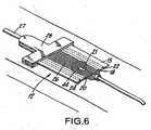
- These elongated sensing electrodes 18, 20 and parallel elongated energizing current electrodes 22, 24provide the configuration necessary to reliably pickup an extravasation where it occurs. This is illustrated in FIG. 6. Specifically, this sensitivity occurs because applicant's structure assures placement of the electrodes 18, 20, 22, 24 around the point where the needle 21 enters the skin. Thus, the extravasation 44 is substantially centered in the measurement zone that is subtended by the inner electrodes 18, 20. In general, the extravasation will be picked up within ten to twenty ccs of extravasation.
- FIGs. 7 and 8illustrate a presently preferred embodiment of the patch.
- the top of the patchis a clear vinyl ply 60.
- This ply 60has on the surface facing the patient, an adhesive which serves to hold the electrodes and to adhere the patch to the patient.
- an adhesivewhich serves to hold the electrodes and to adhere the patch to the patient.
- Under this vinyl ply 60there is a reinforcement ply 62 that provides rigidity for the end of the patch that is to be held by the clamp 28 (see FIG. 1).
- the set of four electrodes 64Just below the reinforcement 62, and in large part in contact with and held by the adhesive side of the ply 60 is the set of four electrodes 64. A discussed in connection with FIG. 2, each electrode has an elongate portion.
- Electrodes 64are essentially similar to the electrode arrangement shown in FIG. 1.
- the patient side of each electrodehas a hydrogel coating to assure good contact against the patient's skin. Since this hydrogel is conducting, it is important that the hydrogel coating only be on the electrode and not on any of the surfaces between the electrode since such would tend to short out the signals involved.
- a clear insulating tape 66 along the short portions of the electrodeshas the important function of minimizing interaction between the short portion of the electrodes and the patient so that it is the long portion of the electrodes 64 which are the effective energization and pick up electrodes.
- the release liner 68having a perforated line 70 that provides the base liner of the patch.
- the release liner(which is the liner 19 in FIG. 1) can be bent back initially so that the patch can be placed into the clamp 28 before it is put into use. Then when it is put into use, the main portion of the liner 68 can be removed by ripping it at the perforation line 70 so that the electrodes 64 can be placed against the patient's skin.
- the patient side of the vinyl layer 60has the pressure sensitive adhesive that will adhere the patch firmly to the patient's skin.
- FIG. 7shows the assembly of the FIG. 8 plies with the clear vinyl ply omitted.
- the overall dimensionsare about 9,4 cm by 5,84 cm (3.7 inches by 2.3 inches).
- the electrodes 64are each about 0,51 cm (0.2 inches) wide and the elongate portions are about 5,08 cm (two inches).
- the hydrogel coating in the electrodes 64ends at the line 72.
- the spacing between the inboard edges of the inner electrodesis about 1,78 cm (0.70 inches) and the spacing between the inboard edges of the outer pair of electrodes is about 3,81 cm (1.5 inches).
Landscapes
- Health & Medical Sciences (AREA)
- Life Sciences & Earth Sciences (AREA)
- Engineering & Computer Science (AREA)
- Biomedical Technology (AREA)
- Animal Behavior & Ethology (AREA)
- Veterinary Medicine (AREA)
- Public Health (AREA)
- General Health & Medical Sciences (AREA)
- Heart & Thoracic Surgery (AREA)
- Nuclear Medicine, Radiotherapy & Molecular Imaging (AREA)
- Radiology & Medical Imaging (AREA)
- Biophysics (AREA)
- Vascular Medicine (AREA)
- Anesthesiology (AREA)
- Physics & Mathematics (AREA)
- Hematology (AREA)
- Pathology (AREA)
- Medical Informatics (AREA)
- Molecular Biology (AREA)
- Surgery (AREA)
- Cardiology (AREA)
- Infusion, Injection, And Reservoir Apparatuses (AREA)
- Investigating Or Analyzing Materials By The Use Of Electric Means (AREA)
Description
- This invention relates to a device for the detection of extravasation and more particularly to the detection of extravasation of ionic and non-ionic contrast media.
- Extravasation or infiltration is a complication related to the use of power injectors during contrast media infection procedures. When an extravasation occurs, contrast is injected into the tissue surrounding the blood vessel, instead of into the blood vessel itself. The causes for extravasation vary, ranging from operator error in placement of the needle to physiological limitations of the blood vessel to tolerate the rate of fluid administration.
- Complications related to extravasation may be quite severe and may include tissue necrosis. This may require reconstructive surgery to repair.
- Presently, a method for detecting an extravasation is for the operator to visually observe it. However, by the time an extravasation is visually observable, much of the previously discussed damage may have occurred. Other known methods employ the detection of temperature variations (US-A-4 010 749) or use electromagnetic waves (US-A-4 877 034, US-A-5 334 141). Document EP-A-0 784 960 discloses an electrode assembly comprising a plurality of electrodes for electrocardiographic measurement.
- Accordingly, it is an object of the present invention to provide a safe, efficient, inexpensive and reliable means for the early detection of extravasations.
- A very large number of contrast media injection procedures are undertaken each year in the United States; something in the order of ten million. Less than 0.2% of these procedures result in an extravasation. Yet the absolute number is substantial because the base number is so large. The occurrence of an extravasation requires that the procedure be terminated and reinstituted. Accordingly, in a normal situation where an extravasation occurs, early detection is important from the point of view of minimizing the impact on the patient, saving time and providing a timely reinstitution of the procedure.
- Although extravasation is not life-threatening, when it does occur it causes discomfort to the patient. It requires a great deal of attention from the doctor and usually means that a procedure has to be interrupted. Thus, it is important that any extravasation detection technique avoid a false indication of extravasation.
- In relatively rare cases the extravasation can be quite harmful to the patient. Therefore early detection will avoid patient trauma or other injury.
- The false detection of an extravasation results in terminating a procedure. Starting the procedure constitutes unnecessary trauma to the patient and expense. Therefore, any detection technique that gives a noticeable number of false indications will not be used by the doctor.
- Accordingly, it is important that any detection technique to be acceptable combine an extremely small number of false indications of extravasation coupled with a reasonably high specificity to the extravasation event being detected.
- The relatively large number of contrast media injections undertaken coupled with the relatively small percentage of extravasations that occur means that any procedure to be acceptable to the medical profession has to be non-invasive.
- It is an accepted fact that any invasive procedure carries with it risks and trauma. They are to be avoided unless the benefit trade-off warrants such.
- Thus, in order for an extravasation detection technique to be acceptable in this context, it must meet the following objectives.
- First, it has to be inexpensive and be a disposable single use item.
- Second, it must be relatively acceptable to the patient. Therefore, it should be non-invasive and create no pain or other patient problem.
- Third, it has to be easy for the technician or doctor to use and readily fits within the procedure involved in the contrast media injection routine.
- Fourth, and perhaps more importantly, it must provide next to no false indications of extravasation. A false indication would mean stopping a procedure which did not have to be stopped. Thus it follows that the technique must be specific to extravasation and non-responsive to other phenomenon such as the patient moving his or her arm.
- Only a device that meets the above criteria (a) will be safe, (b) have technicians and doctors willing to use it, (c) have patients accept it and (d) have it come within the economic requirements of the institution providing the media injection procedure.
- The present invention relates to an extravasation detection device. The extravasation device is an electrode patch for sensing certain electrical information.
- The electrode patch has a body portion which is adapted to be removably affixed to the skin of a patient. Outer and inner pairs of elongated electrodes are deployed along the body of the patch. The inner pair defines a measuring zone which is shaped and dimensioned to encompass the tip of the needle within the zone. The zone is small enough to optimize sensitivity yet large enough to facilitate placement of the patch over the needle tip. When the body of the patch is affixed to the skin of the patient and alternating electrical energy is applied to the outer electrodes, a field is provided which induces a signal in the inner electrodes, which field is a function of the impedance of the tissue of the measuring zone.
- Information from the electrode patch is gathered and processed in order to calculate tissue impedance. The presence of an extravasation is determined by interpreting the tissue impedance measurement and, in that way, extravasations can be detected early. A method for determining the extravasation includes a first step of determining a pre-injection baseline measurement of the tissue impedance.
- The electrode patch is affixed so that the measuring zone encompasses the tip of the needle. Energizing the outer pair of electrodes induces a signal in the inner pair of electrodes as a function of the impedance of the body tissue in the measuring zone. Tissue impedance is measured during the media injection procedure using the electrical information sensed by the inner pair of electrodes. The characteristics of the change in this impedance from the baseline impedance measurement is determined. This tissue impedance is monitored during the injection procedure. A predetermined characteristic of the change in tissue impedance indicates extravasation.
- FIG. 1 is an overall perspective view with parts separated of the underside of the preferred embodiment, illustrating the backing paper peeling off the adhesive-backed body of the electrode patch with an open spring clip connector adjacent.
- FIG. 2 is a top plan view of the electrode-patch, illustrating the conductive electrode strips within the patch.
- FIG 3 is a perspective view of the lower jaw of the spring clip connector with a typical contact and hardware exploded off.
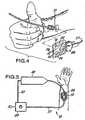
- FIG 4 is a perspective view of a typical method of application, with patch and clip shown prior to placement over the point of needle insertion.
- FIG 5 is a diagrammatic plan view of a typical application and apparatus hook-up.
- FIG 6 is a diagrammatic plan view of the patch in place on a patient showing, in idealized form, the relation between an extravasation and the measuring zone.
- FIG. 7 is a bottom plan view of a presently preferred embodiment of the patch similar to that shown in FIG. 2 except that the clear release liner or
ply 68 that is the base or bottom ply is omitted from FIG. 7. - FIG. 8 is an exploded view of the FIG. 7 patch showing the plies and elements which constitute the patch.
- Referring now to the drawings, the
reference numeral 10 generally denotes an extravasation detection system. Extravasation detection system 10 includes anelectrode patch 12 capable of sensing certain electrical information.Electrode patch 12, as best shown in Fig 1, includes aPVC body 15 and anadhesive backing 17.Adhesive backing 17 is protected by a clearrelease backing sheet 19.Electrode patch 12 is formed with four spaced apart electrodes thereon, twoinner surface electrodes inner electrodes 18, 20 aspace 26 is provided.Space 26 is shaped and dimensioned to permit aneedle 21 to be placed thereunder and to optimize the sensitivity of the system for the depth of the needle tip within the tissue during a typical injection. By usingadhesive backing 15,electrode patch 12 can be easily applied to, and removed from the skin.Electrode patch 12 is provided with acoupling region 23 shaped and dimensioned to fit within aclip 28.Clip 28 is provided withelectrical contacts surface electrodes patch 12 is placed withinclip 28. In apreferred embodiment clip 28 includes a spring 25.Clip 28 haselectrical leads electrical leads Clip 28 further includes afirst conduit 27 housing leads 50, 52, 54, 56 which connects to adevice 29 which interprets the data sensed byelectrode patch 12 and asecond conduit 40 which connects to aCT injector 42.Conduit 40 has capability to halt operation ofinjector 42 in the event an extravasation has been detected or to convey this information toinjector 42.- In one embodiment,
electrodes vertical section vertical section 18b, 20b, 22b, 24b. Each electrode has a total length of about 7,62 cm (3 inches) and a width of about 0,47 cm (3/16 of an inch).Inner electrodes outer electrodes - In that embodiment, the
electrode patch 12 has a length of about 7,62 cm (3 inches) and a width, at its widest point, of about 5,08 cm (2 inches). - In use, the extravasation detective system works as follows. A
syringe needle 21 is introduced into the patient's vasculature. Therelease backing 19 is removed from thepatch body 15 and theelectrode patch 12 is then adhered to the patient's skin usingadhesive backing 17. As heretofore mentioned,patch 12 is positioned such that the needle tip is covered by thespace 26.Electrode patch 12 is clipped intoclip 28 viacoupling region 23 so thatsurface electrodes electrical contacts Clip 28 is then connected throughconduit 27 to impedance monitoring and interpreting circuitry indevice 29. The provision of the short vertical sections allows use of one clip for all electrical connections without compromising the spacing of the surface electrodes in themeasurement area 26 of theelectrode patch 12 where measurements are being made. - Preliminary data is collected to determine the tissue impedance before any injection is made. An injection is then started using
injector 42. Continuous calculations of tissue impedance are made during the injection procedure. An extravasation is deemed to have occurred if during the injection procedure the impedance change shows a fairly consistent slope of at least plus or minus 0.5 ohms per second when material is being infused into the vasculature at a rate of more than 0.25 milliliters per second. It is contemplated that, in certain embodiments, if it is determined that such an extravasation has occurred, there will be an automatic stop mechanism to cease the injection of the media, viaconduit 40 or in the alternative some visual or other type of warning signal. Ionic contrast media has a lower impedance than tissue and will cause a decrease in tissue impedance during an extravasation. Non-ionic contrast media has a higher impedance than tissue and will cause an increase in tissue impedance during an extravasation. - In order to have the appropriate data derived from the electrode patch 12 a constant alternating current is applied to the two
outer electrodes Inner electrodes Device 10 provides a method of detecting extravasations. The method includes the steps of determining a pre-injection of baseline measurement for tissue impedance. It also involves the step of determining the amount of change in tissue impedance which indicates an extravasation.- Further, the method involves the step of monitoring tissue impedance during an injection procedure to ascertain if the amount of change previously determined indicates an extravasation has occurred.
- The aforementioned method, and
system 10, has been used in conjunction with injections of both ionic and non-ionic contrast media to determine the existence of extravasation. - The slope change which is indicative of an extravasation was derived from a series of tests done on animals. Animals were intravenously injected, with both ionic and non-ionic contrast media. Prior to each injection, a measurement of tissue impedance was made and during the course of the injections continuous measurements of tissue impedance were made. It was found that when the injections were intravenous (no extravasation) there was very little change in impedance over time. A second series of ionic and non-ionic contrast media were also made.
- These injections were deliberately made out of the vasculature to simulate an extravasation. During these injections, a substantial change in tissue impedance occurred almost instantaneously. Tissue impedance was plotted as a function of time to determine the slope change indicative of an extravasation.
- Set forth below in Table 1 is a summary of four studies done on dogs in the aforementioned manner. Tables 2-5 are the underlying studies summarized in Table 1.
Table 1 Summary of Data From Five Dogs Variable I.V. Infusion Ionic Media Extravasation Ionic Media LV. Infusion Non-Toxic Media Extravasation Non-Ionic Media Resting Impedance 36 Ohms 35.2 Ohms 29.4 Ohms 32.6 Ohms Slope 9.1% per minute -163% per minute 20.0% per minute 172% per minute TABLE 2 Results of Intravenous Injection of Ionic Contrast in 5 Dogs Dog 1 Dog 2 Dog 3 Dog 4 Dog 5 Mean (S.D.) Leg L R R L R Baseline Resist- ance 30 Ohms 47 Ohms 29 Ohms 36 Ohms 38 Ohms 36.0 (7.2) Injected Volume 20cc 10cc 10cc 15cc 50cc 21.0cc (16.7cc) %ΔZ/ml 0.05 0.30 0.16 0.13 0.08 0.14(0.10) ΔOhms/ml 0.015 0.14 0.05 0.05 0.03 0.06 (0.05) %ΔZ/min 5.4 18.0 10.0 7.5 4.6 9.1 (5.4) TABLE 3 Results of Extravasation of Ionic Contrast in 5 Dogs Dog 1 Dog 2 Dog 3 Dog 4 Dog 5 Mean (S.D.) Leg L R R L R Baseline Resistance 30 Ohms 47 Ohms 30 Ohms 37 Ohms 32 Ohms 35.2(7.2) Injected Volume 10cc 6cc 3cc 6cc 5cc 6.0cc (2.5cc) %ΔZ/ml -2.3 -4.0 -1.3 -2.0 -4.0 -2.7(1.2) ΔOhms/ml -0.69 -1.9 -0.38 -0.74 -1.28 -1.0 (0.6) %ΔZ/min -140.0 -240.0 -75.0 -120.0 -240.0 -163.0(74) TABLE 4 Results of Intravenous Injection of Non-Ionic Contrast in 5 Dogs Dog 1 Dog 2 Dog 3 Dog 4 Dog 5 Mean (S.D.) Leg R L L R L Baseline Resistance 30 Ohms 24 Ohms 27 Ohms 35 Ohms 31 Ohms 29.4(4.2) Injected Volume 10cc 10cc 6cc 4cc 10cc 8.0cc (2.8cc) %ΔZ/ml 0.30 0.43 0.32 0.11 0.50 0.33 (0.15) ΔOhms/ml 0.09 0.10 0.09 0.04 0.16 0.10 (0.4) %ΔZ/mim 18.0 26.0 19.2 6.7 30.0 20.0(8.9) TABLE 5 Results of Extravasation of Non-Ionic Contrast in 5 Dogs Dog 1 Dog 2 Dog 3 Dog 4 Dog 5 Mean (S.D.) Leg R L L R L Baseline 30 Resistance Ohms 24 Ohms 28 Ohms 32 Ohms 49 Ohms 32.6 (9.6) Injected Volume 5cc 5cc 3cc 4cc 3cc 4.0cc (1.0cc) %ΔZ/ml 1.4 3.0 4.0 1.9 4.1 2.9(1.2) ΔOhms/ml 0.41 0.72 1.12 0.60 2.0 1.0(0.6) %ΔZ/min 81.6 180.0 240.0 112.5 246.0 172.0 (74.0) Device 10 and the method associated therewith, although thus far only used to determine extravasations of ionic and non-ionic contrast media, may be useful to determine extravasations of other types of injectable fluids.- One value of an extravasation detection system employing au electrode patch is that it involves a non-invasive procedure. Another important consideration is that the electrode configuration adequately encompasses and responds to the extravasation.
- During a procedure when the needle is in place within a vein, one cannot visualize exactly where the needle tip is. Since the extravasation occurs at the needle tip, one cannot be certain of where that extravasation will precisely occur along the path of the blood vessel. This electrode patch with its elongated measuring zone 26 (between the
pickup electrodes - Furthermore, it is important that these
sensing electrodes opening 26 between them that is shown in FIG. 2 so that the zone under thatspace 26 that is within the patient's body will be sensed if an extravasation occurs. - These
elongated sensing electrodes current electrodes electrodes needle 21 enters the skin. Thus, theextravasation 44 is substantially centered in the measurement zone that is subtended by theinner electrodes - It is the geometric configuration set forth in the above referenced application which meets the objective of providing substantial assurance that an extravasation will be detected yet nearly completely avoid providing a false indication of extravasation.
- FIGs. 7 and 8 illustrate a presently preferred embodiment of the patch. As best seen in the exploded view of FIG. 8, the top of the patch is a clear vinyl ply 60. This
ply 60, has on the surface facing the patient, an adhesive which serves to hold the electrodes and to adhere the patch to the patient. Under this vinyl ply 60, there is areinforcement ply 62 that provides rigidity for the end of the patch that is to be held by the clamp 28 (see FIG. 1). Just below thereinforcement 62, and in large part in contact with and held by the adhesive side of theply 60 is the set of fourelectrodes 64. A discussed in connection with FIG. 2, each electrode has an elongate portion. These elongate portions are the active portions for providing the field and for picking up the signal. Theseelectrodes 64 are essentially similar to the electrode arrangement shown in FIG. 1. The patient side of each electrode has a hydrogel coating to assure good contact against the patient's skin. Since this hydrogel is conducting, it is important that the hydrogel coating only be on the electrode and not on any of the surfaces between the electrode since such would tend to short out the signals involved. A clear insulatingtape 66 along the short portions of the electrodes has the important function of minimizing interaction between the short portion of the electrodes and the patient so that it is the long portion of theelectrodes 64 which are the effective energization and pick up electrodes. Finally, there is theclear release liner 68 having aperforated line 70 that provides the base liner of the patch. As shown in FIG 1, the release liner (which is theliner 19 in FIG. 1) can be bent back initially so that the patch can be placed into theclamp 28 before it is put into use. Then when it is put into use, the main portion of theliner 68 can be removed by ripping it at theperforation line 70 so that theelectrodes 64 can be placed against the patient's skin. The patient side of thevinyl layer 60 has the pressure sensitive adhesive that will adhere the patch firmly to the patient's skin. - FIG. 7 shows the assembly of the FIG. 8 plies with the clear vinyl ply omitted. The overall dimensions are about 9,4 cm by 5,84 cm (3.7 inches by 2.3 inches). The
electrodes 64 are each about 0,51 cm (0.2 inches) wide and the elongate portions are about 5,08 cm (two inches). The hydrogel coating in theelectrodes 64 ends at theline 72. The spacing between the inboard edges of the inner electrodes is about 1,78 cm (0.70 inches) and the spacing between the inboard edges of the outer pair of electrodes is about 3,81 cm (1.5 inches).
Claims (15)
- A device for use with a non-invasive detection system to detect extravasation when fluid is delivered into a patient's vascular system, comprising:a) an outer pair of elongated electrodes (22, 24) and an inner pair of elongated electrodes (18, 20) deployed along a patch (12);b) said inner pair of electrodes being spaced from one another on either side of a centre line, said inner pair defining a measuring zone (26), said measuring zone (26) being shaped and dimensioned to encompass within said zone an end of a channel (21) inserted in the patient's vascular system for delivering fluid into the vascular system, said zone (26) being spaced to provide adequate sensitivity and long enough to facilitate placement of the end of the channel (21) within the measuring zone (26);c) each of said outer pair of electrodes being outward, relative to said centre line, of a respective one of said inner electrodes (18, 20);d) means for providing energization of said outer electrodes for providing a field which induces a signal in said inner electrodes that is a function of the impedance of the tissue in said measuring zone.
- A device as claimed in claim 1, wherein said zone is small enough to optimize sensitivity.
- A device as claimed in claim 1, wherein said zone is of uniform sensitivity and sized to encompass the end of the channel (21).
- The device of any preceding claim wherein the electrodes are substantially the same length.
- The device of any preceding claim wherein each electrode (18, 20, 22, 24) is about 7.6 cm (3 inches) in length, and about 0.48 cm (3/16th of an inch) wide.
- The device of any preceding claim, wherein the electrodes (18, 20, 22, 24) are silver/silver chloride strips.
- The device of any preceding claim wherein a hydrogel material is placed on the electrodes (18, 20, 22, 24).
- The device of any preceding claim wherein the length of the electrodes (18, 20, 22, 24) are parallel relative to each other.
- The device of any preceding claim, wherein said patch is adapted to be affixed to a patient's skin.
- The device of any preceding claim, wherein the end of a channel inserted in the patient's vascular system is a needle tip (21).
- The device of any preceding claim, wherein each of the electrodes includes a coupling region (23) capable of being connected to a clip (28) having electrical contacts (30, 32, 34, 36).
- The device of any preceding claim, wherein the inner pair of electrodes (18, 20) are separated from each other to encompass a vicinity around the end of the channel and the measuring zone (26) being sized to encompass the vicinity around the end of the channel so that extravasation occurring in said vicinity is within the measuring zone.
- The device of any preceding claim, wherein the means for providing energization is adapted to supply a current in the micro ampere range at a frequency of about 1 kilo-hertz to 20 kilo-hertz.
- The device of any preceding claim, wherein the means for providing energization is adapted to supply a current in the micro ampere range at a frequency of about 20 kilo-hertz.
- The device of any preceding claim, wherein the patch (21) is about 5cm (two inches) in width and about 5cm (two inches) in length.
Priority Applications (1)
| Application Number | Priority Date | Filing Date | Title |
|---|---|---|---|
| DE69735316TDE69735316T2 (en) | 1997-11-26 | 1997-11-26 | Detection of extravasation |
Applications Claiming Priority (2)
| Application Number | Priority Date | Filing Date | Title |
|---|---|---|---|
| PCT/US1997/021945WO1999026686A1 (en) | 1997-11-26 | 1997-11-26 | Extravasation detection |
| EP97949704AEP1032442B1 (en) | 1997-11-26 | 1997-11-26 | Extravasation detection |
Related Parent Applications (1)
| Application Number | Title | Priority Date | Filing Date |
|---|---|---|---|
| EP97949704ADivisionEP1032442B1 (en) | 1997-11-26 | 1997-11-26 | Extravasation detection |
Publications (2)
| Publication Number | Publication Date |
|---|---|
| EP1264610A1 EP1264610A1 (en) | 2002-12-11 |
| EP1264610B1true EP1264610B1 (en) | 2006-03-01 |
Family
ID=22262177
Family Applications (2)
| Application Number | Title | Priority Date | Filing Date |
|---|---|---|---|
| EP02009424AExpired - LifetimeEP1264610B1 (en) | 1997-11-26 | 1997-11-26 | Extravasation Detection |
| EP97949704AExpired - LifetimeEP1032442B1 (en) | 1997-11-26 | 1997-11-26 | Extravasation detection |
Family Applications After (1)
| Application Number | Title | Priority Date | Filing Date |
|---|---|---|---|
| EP97949704AExpired - LifetimeEP1032442B1 (en) | 1997-11-26 | 1997-11-26 | Extravasation detection |
Country Status (8)
| Country | Link |
|---|---|
| EP (2) | EP1264610B1 (en) |
| JP (1) | JP3548117B2 (en) |
| KR (1) | KR20010032477A (en) |
| AU (1) | AU740633B2 (en) |
| CA (1) | CA2311451C (en) |
| DE (2) | DE69727986T2 (en) |
| ES (2) | ES2218707T3 (en) |
| WO (1) | WO1999026686A1 (en) |
Families Citing this family (40)
| Publication number | Priority date | Publication date | Assignee | Title |
|---|---|---|---|---|
| US6408204B1 (en) | 1999-07-28 | 2002-06-18 | Medrad, Inc. | Apparatuses and methods for extravasation detection |
| FR2811878B1 (en)* | 2000-07-19 | 2003-02-07 | C2C | DEVICE FOR ACQUIRING ELECTRIC SIGNALS FROM THE HUMAN BODY AND MORE PARTICULARLY FOR THE ACQUISITION OF ELECTRIC SIGNALS FROM THE HEART |
| US7047058B1 (en) | 2001-02-06 | 2006-05-16 | Medrad, Inc. | Apparatuses, systems and methods for extravasation detection |
| US7147615B2 (en)* | 2001-06-22 | 2006-12-12 | Baxter International Inc. | Needle dislodgement detection |
| CA2455402C (en) | 2001-07-26 | 2011-10-11 | Medrad, Inc. | Electromagnetic sensors for biological tissue applications and methods for their use |
| WO2003009753A2 (en) | 2001-07-26 | 2003-02-06 | Chad Bouton | Detection of fluids in tissue |
| US7138088B2 (en) | 2002-04-10 | 2006-11-21 | Baxter International Inc. | Access disconnection system and methods |
| US7052480B2 (en) | 2002-04-10 | 2006-05-30 | Baxter International Inc. | Access disconnection systems and methods |
| US20040254513A1 (en) | 2002-04-10 | 2004-12-16 | Sherwin Shang | Conductive polymer materials and applications thereof including monitoring and providing effective therapy |
| US7022098B2 (en) | 2002-04-10 | 2006-04-04 | Baxter International Inc. | Access disconnection systems and methods |
| US10155082B2 (en) | 2002-04-10 | 2018-12-18 | Baxter International Inc. | Enhanced signal detection for access disconnection systems |
| US7801583B2 (en) | 2002-12-10 | 2010-09-21 | Neorad As | Extravasation detector |
| GB2396221B (en) | 2002-12-10 | 2006-06-07 | Neorad As | Extravasation detector |
| EP1462141B1 (en)* | 2003-03-26 | 2006-09-20 | Terumo Kabushiki Kaisha | Catheter with puncture sensor |
| JP4698128B2 (en)* | 2003-03-28 | 2011-06-08 | テルモ株式会社 | Catheter with puncture sensor |
| JP4443957B2 (en) | 2003-04-28 | 2010-03-31 | 株式会社根本杏林堂 | Leak detection device and method |
| US8029454B2 (en) | 2003-11-05 | 2011-10-04 | Baxter International Inc. | High convection home hemodialysis/hemofiltration and sorbent system |
| DE102006041265B3 (en)* | 2006-09-02 | 2007-12-06 | Fresenius Medical Care Deutschland Gmbh | Vascular access e.g. butterfly cannula, creating device for extracorporeal blood treatment, has base body with electrically conductive contact component provided at lower side of fin pieces, where body is made of non-conductive material |
| DE102006042336A1 (en)* | 2006-09-08 | 2008-03-27 | Fresenius Medical Care Deutschland Gmbh | Device and method for monitoring access to a patient, in particular a vascular access in an extracorporeal blood treatment |
| FR2928551A1 (en) | 2008-03-14 | 2009-09-18 | Gambro Lundia Ab | PROBE FOR LEAK DETECTION OF MULTI-LAYER FLUID |
| FR2928550A1 (en) | 2008-03-14 | 2009-09-18 | Gambro Lundia Ab | PROBE FOR FLUID LEAK DETECTION WITH SPECIFIC DISTAL PART |
| EP2434950A1 (en) | 2009-05-29 | 2012-04-04 | Gambro Lundia AB | Electrical connector clip for medical sensors |
| US8808218B2 (en) | 2010-01-29 | 2014-08-19 | Baxter International Inc. | Needle placement detection and security device and method |
| US8444585B2 (en) | 2010-01-29 | 2013-05-21 | Baxter International Inc. | Catheter needle retention and placement monitoring system and method |
| GB201001631D0 (en) | 2010-02-01 | 2010-03-17 | Eumedic Ltd | Treatment patch electrode for applying electrical impulses to the body of a patient |
| EP2750595B1 (en) | 2011-09-02 | 2021-02-24 | Battelle Memorial Institute | Wireless and power-source-free extravasation and infiltration detection sensor |
| DE102011113839B4 (en) | 2011-09-21 | 2013-05-02 | Fresenius Medical Care Deutschland Gmbh | Connection terminal for a humidity sensor and arrangement of a humidity sensor and a connection terminal for monitoring a vascular access and device for monitoring a vascular access |
| US20130317368A1 (en) | 2012-03-12 | 2013-11-28 | Ivwatch, Llc | System for Mitigating the Effects of Tissue Blood Volume Changes to Aid in Diagnosing Infiltration or Extravasation in Animalia Tissue |
| JP2014083072A (en)* | 2012-10-19 | 2014-05-12 | Tatsuta Electric Wire & Cable Co Ltd | Electrode connector |
| JP5997001B2 (en)* | 2012-10-19 | 2016-09-21 | タツタ電線株式会社 | Electrode connector |
| US20150335286A1 (en)* | 2014-05-20 | 2015-11-26 | Sle Limited | Electrode array |
| WO2016089307A1 (en)* | 2014-12-02 | 2016-06-09 | Agency for Science,Technology and Research | Sensor patch and sensing device having the same |
| US10195367B2 (en) | 2015-10-19 | 2019-02-05 | Fresenius Medical Care Holdings, Inc. | Medical wetness sensing devices and related systems and methods |
| CN105342613A (en)* | 2015-12-02 | 2016-02-24 | 中国科学院半导体研究所 | Flexible electrode for measuring muscle impedance and preparation method thereof |
| US10441705B2 (en) | 2017-04-05 | 2019-10-15 | Fresenius Medical Care Holdings, Inc. | Medical wetness sensing devices and related systems and methods |
| KR101883136B1 (en)* | 2018-02-13 | 2018-07-27 | 부산대학교 산학협력단 | Infiltration detecting device |
| US11281878B2 (en) | 2018-02-20 | 2022-03-22 | Fresenius Medical Care Holdings, Inc. | Wetness detection with biometric sensor device for use in blood treatment |
| KR102448604B1 (en) | 2020-11-25 | 2022-09-27 | 신한대학교 산학협력단 | Extravasation detection and monitoring device |
| KR102552808B1 (en) | 2021-04-05 | 2023-07-06 | 신한대학교 산학협력단 | Measurement device for extravasation volume |
| KR20230081511A (en)* | 2021-11-30 | 2023-06-07 | (주)엑솔아이티 | Ultra_Thin Patch Type Bio Impedance Measuring System for Detecting and Noticing Infiltration |
Family Cites Families (10)
| Publication number | Priority date | Publication date | Assignee | Title |
|---|---|---|---|---|
| US4010749A (en)* | 1975-05-09 | 1977-03-08 | Shaw Robert F | Method of detecting infiltration of infused liquid by comparing altered skin temperature with skin temperature in area of infiltrated liquid |
| JPS58216036A (en)* | 1982-06-11 | 1983-12-15 | フクダ電子株式会社 | Induction electrode |
| US4877034A (en)* | 1987-06-18 | 1989-10-31 | Smith & Nephew, Inc. | Method and device for detection of tissue infiltration |
| US4877634A (en)* | 1987-07-01 | 1989-10-31 | Microlife Technics, Inc. | Food product containing novel dried compositions with polysaccharides |
| US4846792A (en)* | 1988-03-08 | 1989-07-11 | Baxter International Inc. | Automatic infiltration detection system and method |
| JPH01236036A (en)* | 1988-03-17 | 1989-09-20 | Kazusawa Osawa | Brain wave measuring probe |
| JPH052163Y2 (en)* | 1988-10-05 | 1993-01-20 | ||
| JPH088910B2 (en)* | 1991-11-15 | 1996-01-31 | 日本光電工業株式会社 | Biomedical electrode |
| US5334141A (en)* | 1992-06-26 | 1994-08-02 | Medrad, Inc. | Extravasation detection system and apparatus |
| JP3561858B2 (en)* | 1995-12-28 | 2004-09-02 | 務 大竹 | Medical device with medical electrode body |
- 1997
- 1997-11-26EPEP02009424Apatent/EP1264610B1/ennot_activeExpired - Lifetime
- 1997-11-26DEDE69727986Tpatent/DE69727986T2/ennot_activeExpired - Lifetime
- 1997-11-26AUAU35864/99Apatent/AU740633B2/ennot_activeCeased
- 1997-11-26WOPCT/US1997/021945patent/WO1999026686A1/enactiveIP Right Grant
- 1997-11-26JPJP2000521884Apatent/JP3548117B2/ennot_activeExpired - Fee Related
- 1997-11-26DEDE69735316Tpatent/DE69735316T2/ennot_activeExpired - Lifetime
- 1997-11-26EPEP97949704Apatent/EP1032442B1/ennot_activeExpired - Lifetime
- 1997-11-26ESES97949704Tpatent/ES2218707T3/ennot_activeExpired - Lifetime
- 1997-11-26KRKR1020007005719Apatent/KR20010032477A/ennot_activeWithdrawn
- 1997-11-26CACA002311451Apatent/CA2311451C/ennot_activeExpired - Fee Related
- 1997-11-26ESES02009424Tpatent/ES2261549T3/ennot_activeExpired - Lifetime
Also Published As
| Publication number | Publication date |
|---|---|
| DE69727986D1 (en) | 2004-04-08 |
| WO1999026686A1 (en) | 1999-06-03 |
| EP1032442B1 (en) | 2004-03-03 |
| AU3586499A (en) | 1999-06-15 |
| JP3548117B2 (en) | 2004-07-28 |
| KR20010032477A (en) | 2001-04-25 |
| DE69727986T2 (en) | 2005-01-05 |
| CA2311451C (en) | 2007-08-21 |
| JP2001523532A (en) | 2001-11-27 |
| ES2261549T3 (en) | 2006-11-16 |
| EP1264610A1 (en) | 2002-12-11 |
| AU740633B2 (en) | 2001-11-08 |
| ES2218707T3 (en) | 2004-11-16 |
| EP1032442A1 (en) | 2000-09-06 |
| CA2311451A1 (en) | 1999-06-03 |
| DE69735316T2 (en) | 2006-12-21 |
| DE69735316D1 (en) | 2006-04-27 |
Similar Documents
| Publication | Publication Date | Title |
|---|---|---|
| EP1264610B1 (en) | Extravasation Detection | |
| US5964703A (en) | Extravasation detection electrode patch | |
| USRE38879E1 (en) | Extravasation detection technique | |
| US20240408299A1 (en) | Patch delivery device with skin contact sensor | |
| US6190370B1 (en) | Devices, systems and methods for determining proper placement of epidural catheters | |
| EP0678308B1 (en) | Transcutaneous sensor insertion set | |
| EP1401518B1 (en) | Needle dislodgement detection | |
| USRE38695E1 (en) | Extravasation detection electrode patch | |
| EP1032441B1 (en) | Extravasation detection device | |
| US20080132797A1 (en) | Monitoring infusion of a substance | |
| AU2003288417B2 (en) | Extravasation detector | |
| AU1005002A (en) | Extravasation detection | |
| AU1196902A (en) | Extravasation detection | |
| EP4355197A2 (en) | Smart intravenous catheter system | |
| CA2260080A1 (en) | Devices, systems and methods for determining proper placement of epidural catheters |
Legal Events
| Date | Code | Title | Description |
|---|---|---|---|
| PUAI | Public reference made under article 153(3) epc to a published international application that has entered the european phase | Free format text:ORIGINAL CODE: 0009012 | |
| AC | Divisional application: reference to earlier application | Ref document number:1032442 Country of ref document:EP | |
| AK | Designated contracting states | Kind code of ref document:A1 Designated state(s):DE ES FR GB IT | |
| 17P | Request for examination filed | Effective date:20030609 | |
| AKX | Designation fees paid | Designated state(s):DE ES FR GB IT | |
| 17Q | First examination report despatched | Effective date:20040622 | |
| GRAP | Despatch of communication of intention to grant a patent | Free format text:ORIGINAL CODE: EPIDOSNIGR1 | |
| GRAS | Grant fee paid | Free format text:ORIGINAL CODE: EPIDOSNIGR3 | |
| GRAA | (expected) grant | Free format text:ORIGINAL CODE: 0009210 | |
| AC | Divisional application: reference to earlier application | Ref document number:1032442 Country of ref document:EP Kind code of ref document:P | |
| AK | Designated contracting states | Kind code of ref document:B1 Designated state(s):DE ES FR GB IT | |
| PG25 | Lapsed in a contracting state [announced via postgrant information from national office to epo] | Ref country code:IT Free format text:LAPSE BECAUSE OF FAILURE TO SUBMIT A TRANSLATION OF THE DESCRIPTION OR TO PAY THE FEE WITHIN THE PRESCRIBED TIME-LIMIT;WARNING: LAPSES OF ITALIAN PATENTS WITH EFFECTIVE DATE BEFORE 2007 MAY HAVE OCCURRED AT ANY TIME BEFORE 2007. THE CORRECT EFFECTIVE DATE MAY BE DIFFERENT FROM THE ONE RECORDED. Effective date:20060301 | |
| REG | Reference to a national code | Ref country code:GB Ref legal event code:FG4D | |
| REF | Corresponds to: | Ref document number:69735316 Country of ref document:DE Date of ref document:20060427 Kind code of ref document:P | |
| ET | Fr: translation filed | ||
| REG | Reference to a national code | Ref country code:ES Ref legal event code:FG2A Ref document number:2261549 Country of ref document:ES Kind code of ref document:T3 | |
| PLBE | No opposition filed within time limit | Free format text:ORIGINAL CODE: 0009261 | |
| STAA | Information on the status of an ep patent application or granted ep patent | Free format text:STATUS: NO OPPOSITION FILED WITHIN TIME LIMIT | |
| 26N | No opposition filed | Effective date:20061204 | |
| REG | Reference to a national code | Ref country code:GB Ref legal event code:732E | |
| REG | Reference to a national code | Ref country code:FR Ref legal event code:TP | |
| REG | Reference to a national code | Ref country code:ES Ref legal event code:PC2A | |
| REG | Reference to a national code | Ref country code:FR Ref legal event code:PLFP Year of fee payment:19 | |
| PGFP | Annual fee paid to national office [announced via postgrant information from national office to epo] | Ref country code:GB Payment date:20151127 Year of fee payment:19 Ref country code:DE Payment date:20151127 Year of fee payment:19 Ref country code:IT Payment date:20151124 Year of fee payment:19 | |
| PGFP | Annual fee paid to national office [announced via postgrant information from national office to epo] | Ref country code:FR Payment date:20151117 Year of fee payment:19 Ref country code:ES Payment date:20151126 Year of fee payment:19 | |
| REG | Reference to a national code | Ref country code:DE Ref legal event code:R119 Ref document number:69735316 Country of ref document:DE | |
| GBPC | Gb: european patent ceased through non-payment of renewal fee | Effective date:20161126 | |
| REG | Reference to a national code | Ref country code:FR Ref legal event code:ST Effective date:20170731 | |
| PG25 | Lapsed in a contracting state [announced via postgrant information from national office to epo] | Ref country code:FR Free format text:LAPSE BECAUSE OF NON-PAYMENT OF DUE FEES Effective date:20161130 Ref country code:IT Free format text:LAPSE BECAUSE OF NON-PAYMENT OF DUE FEES Effective date:20161126 | |
| PG25 | Lapsed in a contracting state [announced via postgrant information from national office to epo] | Ref country code:GB Free format text:LAPSE BECAUSE OF NON-PAYMENT OF DUE FEES Effective date:20161126 Ref country code:DE Free format text:LAPSE BECAUSE OF NON-PAYMENT OF DUE FEES Effective date:20170601 | |
| REG | Reference to a national code | Ref country code:ES Ref legal event code:FD2A Effective date:20180507 | |
| PG25 | Lapsed in a contracting state [announced via postgrant information from national office to epo] | Ref country code:ES Free format text:LAPSE BECAUSE OF FAILURE TO SUBMIT A TRANSLATION OF THE DESCRIPTION OR TO PAY THE FEE WITHIN THE PRESCRIBED TIME-LIMIT Effective date:20060301 | |
| PG25 | Lapsed in a contracting state [announced via postgrant information from national office to epo] | Ref country code:ES Free format text:LAPSE BECAUSE OF FAILURE TO SUBMIT A TRANSLATION OF THE DESCRIPTION OR TO PAY THE FEE WITHIN THE PRESCRIBED TIME-LIMIT Effective date:20161127 |