EP1263329B9 - Sheaths for implantable fixation devices - Google Patents
Sheaths for implantable fixation devicesDownload PDFInfo
- Publication number
- EP1263329B9 EP1263329B9EP01916648AEP01916648AEP1263329B9EP 1263329 B9EP1263329 B9EP 1263329B9EP 01916648 AEP01916648 AEP 01916648AEP 01916648 AEP01916648 AEP 01916648AEP 1263329 B9EP1263329 B9EP 1263329B9
- Authority
- EP
- European Patent Office
- Prior art keywords
- sheath
- tubes
- graft
- bone
- screw
- Prior art date
- Legal status (The legal status is an assumption and is not a legal conclusion. Google has not performed a legal analysis and makes no representation as to the accuracy of the status listed.)
- Expired - Lifetime
Links
- 210000004872soft tissueAnatomy0.000claimsdescription30
- 239000000463materialSubstances0.000claimsdescription17
- 239000003795chemical substances by applicationSubstances0.000claimsdescription14
- 239000003814drugSubstances0.000claimsdescription7
- 229940124597therapeutic agentDrugs0.000claimsdescription7
- 239000003102growth factorSubstances0.000claimsdescription4
- 230000002138osteoinductive effectEffects0.000claimsdescription4
- 239000000560biocompatible materialSubstances0.000claimsdescription3
- 229920000747poly(lactic acid)Polymers0.000claimsdescription2
- 239000004626polylactic acidSubstances0.000claimsdescription2
- 229920000954PolyglycolidePolymers0.000claims1
- 239000004633polyglycolic acidSubstances0.000claims1
- 238000000034methodMethods0.000abstractdescription16
- 210000000988bone and boneAnatomy0.000description77
- 210000000689upper legAnatomy0.000description15
- AEMRFAOFKBGASW-UHFFFAOYSA-NGlycolic acidChemical compoundOCC(O)=OAEMRFAOFKBGASW-UHFFFAOYSA-N0.000description6
- 239000000835fiberSubstances0.000description6
- 239000007787solidSubstances0.000description5
- 210000002303tibiaAnatomy0.000description5
- 210000001264anterior cruciate ligamentAnatomy0.000description4
- 210000003041ligamentAnatomy0.000description4
- 239000004005microsphereSubstances0.000description4
- 229920000642polymerPolymers0.000description4
- 238000001356surgical procedureMethods0.000description4
- 210000001519tissueAnatomy0.000description4
- 239000008186active pharmaceutical agentSubstances0.000description3
- 238000002513implantationMethods0.000description3
- 238000003780insertionMethods0.000description3
- 230000037431insertionEffects0.000description3
- 239000000853adhesiveSubstances0.000description2
- 230000001070adhesive effectEffects0.000description2
- 239000012867bioactive agentSubstances0.000description2
- OSGAYBCDTDRGGQ-UHFFFAOYSA-Lcalcium sulfateChemical compound[Ca+2].[O-]S([O-])(=O)=OOSGAYBCDTDRGGQ-UHFFFAOYSA-L0.000description2
- 238000004891communicationMethods0.000description2
- 230000012010growthEffects0.000description2
- -1hydroxyapaptiteSubstances0.000description2
- 238000011065in-situ storageMethods0.000description2
- JVTAAEKCZFNVCJ-UHFFFAOYSA-Nlactic acidChemical compoundCC(O)C(O)=OJVTAAEKCZFNVCJ-UHFFFAOYSA-N0.000description2
- 102000004169proteins and genesHuman genes0.000description2
- 108090000623proteins and genesProteins0.000description2
- 238000005245sinteringMethods0.000description2
- 238000005507sprayingMethods0.000description2
- OYPRJOBELJOOCE-UHFFFAOYSA-NCalciumChemical compound[Ca]OYPRJOBELJOOCE-UHFFFAOYSA-N0.000description1
- 102000004127CytokinesHuman genes0.000description1
- 108090000695CytokinesProteins0.000description1
- 208000034693LacerationDiseases0.000description1
- 102000010780Platelet-Derived Growth FactorHuman genes0.000description1
- 108010038512Platelet-Derived Growth FactorProteins0.000description1
- ZLMJMSJWJFRBEC-UHFFFAOYSA-NPotassiumChemical compound[K]ZLMJMSJWJFRBEC-UHFFFAOYSA-N0.000description1
- 238000010420art techniqueMethods0.000description1
- 230000004323axial lengthEffects0.000description1
- 230000008468bone growthEffects0.000description1
- 238000009954braidingMethods0.000description1
- 239000011575calciumSubstances0.000description1
- 229910052791calciumInorganic materials0.000description1
- 239000001506calcium phosphateSubstances0.000description1
- 239000001175calcium sulphateSubstances0.000description1
- 235000011132calcium sulphateNutrition0.000description1
- 239000000919ceramicSubstances0.000description1
- 230000008602contractionEffects0.000description1
- 238000013270controlled releaseMethods0.000description1
- 238000009945crochetingMethods0.000description1
- 238000005520cutting processMethods0.000description1
- 238000011161developmentMethods0.000description1
- 230000018109developmental processEffects0.000description1
- 238000007598dipping methodMethods0.000description1
- 238000010410dustingMethods0.000description1
- 238000005538encapsulationMethods0.000description1
- 238000001125extrusionMethods0.000description1
- 239000007943implantSubstances0.000description1
- 230000010354integrationEffects0.000description1
- 210000003127kneeAnatomy0.000description1
- 238000009940knittingMethods0.000description1
- 229920002521macromoleculePolymers0.000description1
- 239000000203mixtureSubstances0.000description1
- 230000000921morphogenic effectEffects0.000description1
- 239000002105nanoparticleSubstances0.000description1
- 210000000963osteoblastAnatomy0.000description1
- 229920000728polyesterPolymers0.000description1
- 239000011591potassiumSubstances0.000description1
- 229910052700potassiumInorganic materials0.000description1
- 238000002360preparation methodMethods0.000description1
- 238000003825pressingMethods0.000description1
- 230000001737promoting effectEffects0.000description1
- 230000002787reinforcementEffects0.000description1
- 238000011160researchMethods0.000description1
- 210000000130stem cellAnatomy0.000description1
- 239000000758substrateSubstances0.000description1
- 210000002435tendonAnatomy0.000description1
- 230000008467tissue growthEffects0.000description1
- QORWJWZARLRLPR-UHFFFAOYSA-Htricalcium bis(phosphate)Chemical compound[Ca+2].[Ca+2].[Ca+2].[O-]P([O-])([O-])=O.[O-]P([O-])([O-])=OQORWJWZARLRLPR-UHFFFAOYSA-H0.000description1
- 229940078499tricalcium phosphateDrugs0.000description1
- 229910000391tricalcium phosphateInorganic materials0.000description1
- 235000019731tricalcium phosphateNutrition0.000description1
- 238000009941weavingMethods0.000description1
- 238000003466weldingMethods0.000description1
- 238000004804windingMethods0.000description1
Images


Classifications
- A—HUMAN NECESSITIES
- A61—MEDICAL OR VETERINARY SCIENCE; HYGIENE
- A61F—FILTERS IMPLANTABLE INTO BLOOD VESSELS; PROSTHESES; DEVICES PROVIDING PATENCY TO, OR PREVENTING COLLAPSING OF, TUBULAR STRUCTURES OF THE BODY, e.g. STENTS; ORTHOPAEDIC, NURSING OR CONTRACEPTIVE DEVICES; FOMENTATION; TREATMENT OR PROTECTION OF EYES OR EARS; BANDAGES, DRESSINGS OR ABSORBENT PADS; FIRST-AID KITS
- A61F2/00—Filters implantable into blood vessels; Prostheses, i.e. artificial substitutes or replacements for parts of the body; Appliances for connecting them with the body; Devices providing patency to, or preventing collapsing of, tubular structures of the body, e.g. stents
- A61F2/02—Prostheses implantable into the body
- A61F2/08—Muscles; Tendons; Ligaments
- A61F2/0811—Fixation devices for tendons or ligaments
- A—HUMAN NECESSITIES
- A61—MEDICAL OR VETERINARY SCIENCE; HYGIENE
- A61B—DIAGNOSIS; SURGERY; IDENTIFICATION
- A61B17/00—Surgical instruments, devices or methods
- A61B17/04—Surgical instruments, devices or methods for suturing wounds; Holders or packages for needles or suture materials
- A61B17/0401—Suture anchors, buttons or pledgets, i.e. means for attaching sutures to bone, cartilage or soft tissue; Instruments for applying or removing suture anchors
- A—HUMAN NECESSITIES
- A61—MEDICAL OR VETERINARY SCIENCE; HYGIENE
- A61B—DIAGNOSIS; SURGERY; IDENTIFICATION
- A61B17/00—Surgical instruments, devices or methods
- A61B17/34—Trocars; Puncturing needles
- A61B17/3417—Details of tips or shafts, e.g. grooves, expandable, bendable; Multiple coaxial sliding cannulas, e.g. for dilating
- A61B17/3421—Cannulas
- A61B17/3431—Cannulas being collapsible, e.g. made of thin flexible material
- A—HUMAN NECESSITIES
- A61—MEDICAL OR VETERINARY SCIENCE; HYGIENE
- A61B—DIAGNOSIS; SURGERY; IDENTIFICATION
- A61B17/00—Surgical instruments, devices or methods
- A61B17/56—Surgical instruments or methods for treatment of bones or joints; Devices specially adapted therefor
- A61B17/58—Surgical instruments or methods for treatment of bones or joints; Devices specially adapted therefor for osteosynthesis, e.g. bone plates, screws or setting implements
- A61B17/68—Internal fixation devices, including fasteners and spinal fixators, even if a part thereof projects from the skin
- A61B17/686—Plugs, i.e. elements forming interface between bone hole and implant or fastener, e.g. screw
- A—HUMAN NECESSITIES
- A61—MEDICAL OR VETERINARY SCIENCE; HYGIENE
- A61F—FILTERS IMPLANTABLE INTO BLOOD VESSELS; PROSTHESES; DEVICES PROVIDING PATENCY TO, OR PREVENTING COLLAPSING OF, TUBULAR STRUCTURES OF THE BODY, e.g. STENTS; ORTHOPAEDIC, NURSING OR CONTRACEPTIVE DEVICES; FOMENTATION; TREATMENT OR PROTECTION OF EYES OR EARS; BANDAGES, DRESSINGS OR ABSORBENT PADS; FIRST-AID KITS
- A61F2/00—Filters implantable into blood vessels; Prostheses, i.e. artificial substitutes or replacements for parts of the body; Appliances for connecting them with the body; Devices providing patency to, or preventing collapsing of, tubular structures of the body, e.g. stents
- A61F2/02—Prostheses implantable into the body
- A61F2/08—Muscles; Tendons; Ligaments
- A—HUMAN NECESSITIES
- A61—MEDICAL OR VETERINARY SCIENCE; HYGIENE
- A61B—DIAGNOSIS; SURGERY; IDENTIFICATION
- A61B17/00—Surgical instruments, devices or methods
- A61B17/56—Surgical instruments or methods for treatment of bones or joints; Devices specially adapted therefor
- A61B17/58—Surgical instruments or methods for treatment of bones or joints; Devices specially adapted therefor for osteosynthesis, e.g. bone plates, screws or setting implements
- A61B17/88—Osteosynthesis instruments; Methods or means for implanting or extracting internal or external fixation devices
- A61B17/8861—Apparatus for manipulating flexible wires or straps
- A—HUMAN NECESSITIES
- A61—MEDICAL OR VETERINARY SCIENCE; HYGIENE
- A61B—DIAGNOSIS; SURGERY; IDENTIFICATION
- A61B17/00—Surgical instruments, devices or methods
- A61B17/56—Surgical instruments or methods for treatment of bones or joints; Devices specially adapted therefor
- A61B17/58—Surgical instruments or methods for treatment of bones or joints; Devices specially adapted therefor for osteosynthesis, e.g. bone plates, screws or setting implements
- A61B17/88—Osteosynthesis instruments; Methods or means for implanting or extracting internal or external fixation devices
- A61B17/8869—Tensioning devices
- A—HUMAN NECESSITIES
- A61—MEDICAL OR VETERINARY SCIENCE; HYGIENE
- A61B—DIAGNOSIS; SURGERY; IDENTIFICATION
- A61B17/00—Surgical instruments, devices or methods
- A61B2017/00004—(bio)absorbable, (bio)resorbable or resorptive
- A—HUMAN NECESSITIES
- A61—MEDICAL OR VETERINARY SCIENCE; HYGIENE
- A61B—DIAGNOSIS; SURGERY; IDENTIFICATION
- A61B17/00—Surgical instruments, devices or methods
- A61B2017/0046—Surgical instruments, devices or methods with a releasable handle; with handle and operating part separable
- A—HUMAN NECESSITIES
- A61—MEDICAL OR VETERINARY SCIENCE; HYGIENE
- A61F—FILTERS IMPLANTABLE INTO BLOOD VESSELS; PROSTHESES; DEVICES PROVIDING PATENCY TO, OR PREVENTING COLLAPSING OF, TUBULAR STRUCTURES OF THE BODY, e.g. STENTS; ORTHOPAEDIC, NURSING OR CONTRACEPTIVE DEVICES; FOMENTATION; TREATMENT OR PROTECTION OF EYES OR EARS; BANDAGES, DRESSINGS OR ABSORBENT PADS; FIRST-AID KITS
- A61F2/00—Filters implantable into blood vessels; Prostheses, i.e. artificial substitutes or replacements for parts of the body; Appliances for connecting them with the body; Devices providing patency to, or preventing collapsing of, tubular structures of the body, e.g. stents
- A61F2/02—Prostheses implantable into the body
- A61F2/30—Joints
- A61F2/30721—Accessories
- A61F2/30749—Fixation appliances for connecting prostheses to the body
- A—HUMAN NECESSITIES
- A61—MEDICAL OR VETERINARY SCIENCE; HYGIENE
- A61F—FILTERS IMPLANTABLE INTO BLOOD VESSELS; PROSTHESES; DEVICES PROVIDING PATENCY TO, OR PREVENTING COLLAPSING OF, TUBULAR STRUCTURES OF THE BODY, e.g. STENTS; ORTHOPAEDIC, NURSING OR CONTRACEPTIVE DEVICES; FOMENTATION; TREATMENT OR PROTECTION OF EYES OR EARS; BANDAGES, DRESSINGS OR ABSORBENT PADS; FIRST-AID KITS
- A61F2/00—Filters implantable into blood vessels; Prostheses, i.e. artificial substitutes or replacements for parts of the body; Appliances for connecting them with the body; Devices providing patency to, or preventing collapsing of, tubular structures of the body, e.g. stents
- A61F2/02—Prostheses implantable into the body
- A61F2/08—Muscles; Tendons; Ligaments
- A61F2/0811—Fixation devices for tendons or ligaments
- A61F2002/0817—Structure of the anchor
- A61F2002/0823—Modular anchors comprising a plurality of separate parts
- A61F2002/0835—Modular anchors comprising a plurality of separate parts with deformation of anchor parts, e.g. expansion of dowel by set screw
- A—HUMAN NECESSITIES
- A61—MEDICAL OR VETERINARY SCIENCE; HYGIENE
- A61F—FILTERS IMPLANTABLE INTO BLOOD VESSELS; PROSTHESES; DEVICES PROVIDING PATENCY TO, OR PREVENTING COLLAPSING OF, TUBULAR STRUCTURES OF THE BODY, e.g. STENTS; ORTHOPAEDIC, NURSING OR CONTRACEPTIVE DEVICES; FOMENTATION; TREATMENT OR PROTECTION OF EYES OR EARS; BANDAGES, DRESSINGS OR ABSORBENT PADS; FIRST-AID KITS
- A61F2/00—Filters implantable into blood vessels; Prostheses, i.e. artificial substitutes or replacements for parts of the body; Appliances for connecting them with the body; Devices providing patency to, or preventing collapsing of, tubular structures of the body, e.g. stents
- A61F2/02—Prostheses implantable into the body
- A61F2/08—Muscles; Tendons; Ligaments
- A61F2/0811—Fixation devices for tendons or ligaments
- A61F2002/0847—Mode of fixation of anchor to tendon or ligament
- A61F2002/0864—Fixation of tendon or ligament between anchor elements, e.g. by additional screws in the anchor, anchor crimped around tendon
- A—HUMAN NECESSITIES
- A61—MEDICAL OR VETERINARY SCIENCE; HYGIENE
- A61F—FILTERS IMPLANTABLE INTO BLOOD VESSELS; PROSTHESES; DEVICES PROVIDING PATENCY TO, OR PREVENTING COLLAPSING OF, TUBULAR STRUCTURES OF THE BODY, e.g. STENTS; ORTHOPAEDIC, NURSING OR CONTRACEPTIVE DEVICES; FOMENTATION; TREATMENT OR PROTECTION OF EYES OR EARS; BANDAGES, DRESSINGS OR ABSORBENT PADS; FIRST-AID KITS
- A61F2/00—Filters implantable into blood vessels; Prostheses, i.e. artificial substitutes or replacements for parts of the body; Appliances for connecting them with the body; Devices providing patency to, or preventing collapsing of, tubular structures of the body, e.g. stents
- A61F2/02—Prostheses implantable into the body
- A61F2/08—Muscles; Tendons; Ligaments
- A61F2/0811—Fixation devices for tendons or ligaments
- A61F2002/0876—Position of anchor in respect to the bone
- A61F2002/0882—Anchor in or on top of a bone tunnel, i.e. a hole running through the entire bone
- A—HUMAN NECESSITIES
- A61—MEDICAL OR VETERINARY SCIENCE; HYGIENE
- A61F—FILTERS IMPLANTABLE INTO BLOOD VESSELS; PROSTHESES; DEVICES PROVIDING PATENCY TO, OR PREVENTING COLLAPSING OF, TUBULAR STRUCTURES OF THE BODY, e.g. STENTS; ORTHOPAEDIC, NURSING OR CONTRACEPTIVE DEVICES; FOMENTATION; TREATMENT OR PROTECTION OF EYES OR EARS; BANDAGES, DRESSINGS OR ABSORBENT PADS; FIRST-AID KITS
- A61F2/00—Filters implantable into blood vessels; Prostheses, i.e. artificial substitutes or replacements for parts of the body; Appliances for connecting them with the body; Devices providing patency to, or preventing collapsing of, tubular structures of the body, e.g. stents
- A61F2/02—Prostheses implantable into the body
- A61F2/30—Joints
- A61F2002/30001—Additional features of subject-matter classified in A61F2/28, A61F2/30 and subgroups thereof
- A61F2002/30003—Material related properties of the prosthesis or of a coating on the prosthesis
- A61F2002/3006—Properties of materials and coating materials
- A61F2002/30062—(bio)absorbable, biodegradable, bioerodable, (bio)resorbable, resorptive
- A—HUMAN NECESSITIES
- A61—MEDICAL OR VETERINARY SCIENCE; HYGIENE
- A61F—FILTERS IMPLANTABLE INTO BLOOD VESSELS; PROSTHESES; DEVICES PROVIDING PATENCY TO, OR PREVENTING COLLAPSING OF, TUBULAR STRUCTURES OF THE BODY, e.g. STENTS; ORTHOPAEDIC, NURSING OR CONTRACEPTIVE DEVICES; FOMENTATION; TREATMENT OR PROTECTION OF EYES OR EARS; BANDAGES, DRESSINGS OR ABSORBENT PADS; FIRST-AID KITS
- A61F2/00—Filters implantable into blood vessels; Prostheses, i.e. artificial substitutes or replacements for parts of the body; Appliances for connecting them with the body; Devices providing patency to, or preventing collapsing of, tubular structures of the body, e.g. stents
- A61F2/02—Prostheses implantable into the body
- A61F2/30—Joints
- A61F2002/30001—Additional features of subject-matter classified in A61F2/28, A61F2/30 and subgroups thereof
- A61F2002/30108—Shapes
- A61F2002/30199—Three-dimensional shapes
- A61F2002/30224—Three-dimensional shapes cylindrical
- A61F2002/30235—Three-dimensional shapes cylindrical tubular, e.g. sleeves
- A—HUMAN NECESSITIES
- A61—MEDICAL OR VETERINARY SCIENCE; HYGIENE
- A61F—FILTERS IMPLANTABLE INTO BLOOD VESSELS; PROSTHESES; DEVICES PROVIDING PATENCY TO, OR PREVENTING COLLAPSING OF, TUBULAR STRUCTURES OF THE BODY, e.g. STENTS; ORTHOPAEDIC, NURSING OR CONTRACEPTIVE DEVICES; FOMENTATION; TREATMENT OR PROTECTION OF EYES OR EARS; BANDAGES, DRESSINGS OR ABSORBENT PADS; FIRST-AID KITS
- A61F2/00—Filters implantable into blood vessels; Prostheses, i.e. artificial substitutes or replacements for parts of the body; Appliances for connecting them with the body; Devices providing patency to, or preventing collapsing of, tubular structures of the body, e.g. stents
- A61F2/02—Prostheses implantable into the body
- A61F2/30—Joints
- A61F2002/30001—Additional features of subject-matter classified in A61F2/28, A61F2/30 and subgroups thereof
- A61F2002/30667—Features concerning an interaction with the environment or a particular use of the prosthesis
- A61F2002/30677—Means for introducing or releasing pharmaceutical products, e.g. antibiotics, into the body
- A—HUMAN NECESSITIES
- A61—MEDICAL OR VETERINARY SCIENCE; HYGIENE
- A61F—FILTERS IMPLANTABLE INTO BLOOD VESSELS; PROSTHESES; DEVICES PROVIDING PATENCY TO, OR PREVENTING COLLAPSING OF, TUBULAR STRUCTURES OF THE BODY, e.g. STENTS; ORTHOPAEDIC, NURSING OR CONTRACEPTIVE DEVICES; FOMENTATION; TREATMENT OR PROTECTION OF EYES OR EARS; BANDAGES, DRESSINGS OR ABSORBENT PADS; FIRST-AID KITS
- A61F2/00—Filters implantable into blood vessels; Prostheses, i.e. artificial substitutes or replacements for parts of the body; Appliances for connecting them with the body; Devices providing patency to, or preventing collapsing of, tubular structures of the body, e.g. stents
- A61F2/02—Prostheses implantable into the body
- A61F2/30—Joints
- A61F2/30767—Special external or bone-contacting surface, e.g. coating for improving bone ingrowth
- A61F2/30907—Nets or sleeves applied to surface of prostheses or in cement
- A61F2002/30909—Nets
- A61F2002/30914—Details of the mesh structure, e.g. disposition of the woven warp and weft wires
- A—HUMAN NECESSITIES
- A61—MEDICAL OR VETERINARY SCIENCE; HYGIENE
- A61F—FILTERS IMPLANTABLE INTO BLOOD VESSELS; PROSTHESES; DEVICES PROVIDING PATENCY TO, OR PREVENTING COLLAPSING OF, TUBULAR STRUCTURES OF THE BODY, e.g. STENTS; ORTHOPAEDIC, NURSING OR CONTRACEPTIVE DEVICES; FOMENTATION; TREATMENT OR PROTECTION OF EYES OR EARS; BANDAGES, DRESSINGS OR ABSORBENT PADS; FIRST-AID KITS
- A61F2/00—Filters implantable into blood vessels; Prostheses, i.e. artificial substitutes or replacements for parts of the body; Appliances for connecting them with the body; Devices providing patency to, or preventing collapsing of, tubular structures of the body, e.g. stents
- A61F2/02—Prostheses implantable into the body
- A61F2/30—Joints
- A61F2/30767—Special external or bone-contacting surface, e.g. coating for improving bone ingrowth
- A61F2/30907—Nets or sleeves applied to surface of prostheses or in cement
- A61F2002/30919—Sleeves
- A—HUMAN NECESSITIES
- A61—MEDICAL OR VETERINARY SCIENCE; HYGIENE
- A61F—FILTERS IMPLANTABLE INTO BLOOD VESSELS; PROSTHESES; DEVICES PROVIDING PATENCY TO, OR PREVENTING COLLAPSING OF, TUBULAR STRUCTURES OF THE BODY, e.g. STENTS; ORTHOPAEDIC, NURSING OR CONTRACEPTIVE DEVICES; FOMENTATION; TREATMENT OR PROTECTION OF EYES OR EARS; BANDAGES, DRESSINGS OR ABSORBENT PADS; FIRST-AID KITS
- A61F2210/00—Particular material properties of prostheses classified in groups A61F2/00 - A61F2/26 or A61F2/82 or A61F9/00 or A61F11/00 or subgroups thereof
- A61F2210/0004—Particular material properties of prostheses classified in groups A61F2/00 - A61F2/26 or A61F2/82 or A61F9/00 or A61F11/00 or subgroups thereof bioabsorbable
- A—HUMAN NECESSITIES
- A61—MEDICAL OR VETERINARY SCIENCE; HYGIENE
- A61F—FILTERS IMPLANTABLE INTO BLOOD VESSELS; PROSTHESES; DEVICES PROVIDING PATENCY TO, OR PREVENTING COLLAPSING OF, TUBULAR STRUCTURES OF THE BODY, e.g. STENTS; ORTHOPAEDIC, NURSING OR CONTRACEPTIVE DEVICES; FOMENTATION; TREATMENT OR PROTECTION OF EYES OR EARS; BANDAGES, DRESSINGS OR ABSORBENT PADS; FIRST-AID KITS
- A61F2220/00—Fixations or connections for prostheses classified in groups A61F2/00 - A61F2/26 or A61F2/82 or A61F9/00 or A61F11/00 or subgroups thereof
- A61F2220/0008—Fixation appliances for connecting prostheses to the body
- A—HUMAN NECESSITIES
- A61—MEDICAL OR VETERINARY SCIENCE; HYGIENE
- A61F—FILTERS IMPLANTABLE INTO BLOOD VESSELS; PROSTHESES; DEVICES PROVIDING PATENCY TO, OR PREVENTING COLLAPSING OF, TUBULAR STRUCTURES OF THE BODY, e.g. STENTS; ORTHOPAEDIC, NURSING OR CONTRACEPTIVE DEVICES; FOMENTATION; TREATMENT OR PROTECTION OF EYES OR EARS; BANDAGES, DRESSINGS OR ABSORBENT PADS; FIRST-AID KITS
- A61F2230/00—Geometry of prostheses classified in groups A61F2/00 - A61F2/26 or A61F2/82 or A61F9/00 or A61F11/00 or subgroups thereof
- A61F2230/0063—Three-dimensional shapes
- A61F2230/0069—Three-dimensional shapes cylindrical
- A—HUMAN NECESSITIES
- A61—MEDICAL OR VETERINARY SCIENCE; HYGIENE
- A61F—FILTERS IMPLANTABLE INTO BLOOD VESSELS; PROSTHESES; DEVICES PROVIDING PATENCY TO, OR PREVENTING COLLAPSING OF, TUBULAR STRUCTURES OF THE BODY, e.g. STENTS; ORTHOPAEDIC, NURSING OR CONTRACEPTIVE DEVICES; FOMENTATION; TREATMENT OR PROTECTION OF EYES OR EARS; BANDAGES, DRESSINGS OR ABSORBENT PADS; FIRST-AID KITS
- A61F2250/00—Special features of prostheses classified in groups A61F2/00 - A61F2/26 or A61F2/82 or A61F9/00 or A61F11/00 or subgroups thereof
- A61F2250/0058—Additional features; Implant or prostheses properties not otherwise provided for
- A61F2250/0067—Means for introducing or releasing pharmaceutical products into the body
- Y—GENERAL TAGGING OF NEW TECHNOLOGICAL DEVELOPMENTS; GENERAL TAGGING OF CROSS-SECTIONAL TECHNOLOGIES SPANNING OVER SEVERAL SECTIONS OF THE IPC; TECHNICAL SUBJECTS COVERED BY FORMER USPC CROSS-REFERENCE ART COLLECTIONS [XRACs] AND DIGESTS
- Y10—TECHNICAL SUBJECTS COVERED BY FORMER USPC
- Y10S—TECHNICAL SUBJECTS COVERED BY FORMER USPC CROSS-REFERENCE ART COLLECTIONS [XRACs] AND DIGESTS
- Y10S623/00—Prosthesis, i.e. artificial body members, parts thereof, or aids and accessories therefor
- Y10S623/902—Method of implanting
- Y10S623/908—Bone
Definitions
- the inventionrelates to devices that fix soft tissue to support structures, particularly devices that fix soft tissue grafts within bone tunnels.
- soft tissue graftsIn certain types of surgical procedures, soft tissue grafts must be fixed within a bone tunnel.
- ACLanterior cruciate ligament
- a ligament graftis harvested from the patient or from a donor, and implanted within the knee by securing one end within a bone tunnel drilled through the tibia, and the other end within a bone tunnel drilled through the femur.
- RosenbergU.S. Patent No. 5,139,520 , which is incorporated herein by reference.
- a ligament graft 10can be fixed within a bone tunnel using a bone screw 12.
- Graft 10is made from e.g., a single or double long strip of soft tissue.
- the middle of the strip(not shown) is first passed in a distal direction through a first tunnel 14 in the tibia into a second tunnel 18 in the femur, and then attached to the femur tunnel (or attached to bone adjacent the femur tunnel) with a femur fixation device (not shown).
- Two approximately equal length segments 19a, 19b of the graftextend proximally from the attached middle portion through tunnels 18 and 14.
- segment 19a and 19b of the graftare then fixed within tibial tunnel 14 by inserting bone screw 12 between the two segments, such that shaft 22 of the screw presses the segments against internal wall 24 of tunnel 14.
- the inventionfeatures a sheath for an implantable fixation device that includes at least three generally parallel tubes arranged to form a ring.
- the ringdefines a central cavity between the tubes that is sized and shaped to receive the fixation device.
- Embodiments of this aspect of the inventionmay include one or more of the following features.
- the central cavitymay include a bore that is coextensive with the tubes.
- the ring of tubesincludes a plurality, e.g., 3, 4, 5, 6, 7, or 8 tubes, and the sheath includes an external sleeve that surrounds the tubes.
- the tubesmay be flexible, and at least some of the tubes are sized and shaped to receive a portion of the soft tissue graft. At least some of the tubes are perforated. For example, in one embodiment, all the tubes have a mesh structure, and the ring of tubes is integrally formed. Further features are defined in claims 10-17.
- the invention sheathmay be used in a method of fixing soft tissue within a bone tunnel that includes: (a) inserting a sheath into the bone tunnel, the sheath having at least three generally parallel tubes arranged to form a ring, the ring defining a central cavity between the tubes; (b) passing segments of the soft tissue through at least two of the tubes; and (c) positioning a fixation device within the central cavity of the ring to compress the tubes between the fixation device and a wall of the bone tunnel, and to compress the soft tissue segments within their respective tubes, thereby fixing the soft tissue within the bone tunnel.
- This methodmay further include one or more of the following features.
- the passing stepis performed prior to inserting the sheath into the bone tunnel.
- the sheathhas exactly four tubes arranged to form the ring, and the passing step includes passing segments of the soft tissue through each of the four tubes.
- the fixation deviceis a bone screw having a shaft, and the positioning step includes positioning the shaft within the central portion of the ring.
- the inventionmay include one or more of the following advantages.
- the flexibility and thinness of certain embodiments of the sheathallows the sheath to conform, e.g., to the shape of the fixation device, or to the shape of a bone tunnel.
- the sheathprotects the soft tissue graft from laceration or cutting by threads of a fixation screw, and reduces twisting of the graft upon insertion of a screw.
- the relief in the sheathe.g., perforations in a wall of the sheath, allows in situ contact between a soft tissue graft and the wall of a bone tunnel, promoting development of Sharpy-like fibers and permanent attachment of the soft tissue to the bone.
- the relieved wallfacilitates improved graft fixation.
- Therapeutic agentssuch as osteoinductors or growth factors, can be disposed on or embedded into the material of the sheath, allowing delivery of the agent directly to the site of fixation.
- Embodiments of the inventionfeature sheaths that surround bone screws and soft tissue grafts to improve fixation of the grafts.
- the sheathis a flexible, mesh tube that surrounds only the bone screw, both the bone screw and the graft, or only the graft.
- the sheathincludes multiple tubes as defined in claim 1.
- a sheath 50has a tube-shaped body 52 that defines a generally cylindrical exterior surface 53 and a generally cylindrical interior 54.
- Body 52is formed from a biocompatible material woven into a mesh structure.
- the meshdefines numerous holes 56 that expose interior 54 to the outside.
- Sheath 50also has two circular, open ends 58a, 58b, allowing a tissue graft to pass entirely through the interior of the sheath.
- Sheath 50is sized and shaped to receive bone screw 12.
- Sheath 50has an internal diameter D 1 greater than the diameter D S of bone screw 12, so that both screw 12 and segments 19a and 19b of graft 10 can fit snugly within the sheath.
- the sheathhas a length L 1 slightly larger than the length L S of screw 12.
- the mesh body 52is thin and flexible, allowing the sheath to adjust to fit snugly surround the screw; body 52 can be compressed to reduce the volume of interior 54, twisted, or stretched. Since sheath 50 is thin and flexible rather than rigid, it cannot on its own shore up soft bone, or fix a graft within a bone tunnel. (i.e., sheath 50 is not designed to be used alone as a fixation device or as a solid, rigid reinforcement of soft bone.)
- the threads forming the mesh body 52are larger in the radial direction than in the axial direction. This difference in thread size results in sheath 50 being less flexible radially than axially. In these embodiments, the diameter D 1 is more resistant to expansion or contraction than length L 1 . In other embodiments, the thread size is equal throughout body 52.
- Diameter D 1is, e.g., between about 8 and 10 mm, and L 1 is, between about 25 and 40 mm. If sheath 50 is designed for a 7x25 bone screw (7 mm diameter, 25 mm length), then L 1 is, e.g., about 30 mm, and D 1 is, e.g., about 9 mm. Most of exterior surface 53 is open. For example, about 40% of the area exterior surface 53 is mesh strands, and about 60% is holes 56. The thickness T 1 the mesh wall of sheath 50 is, for example, less than about 0.3 mm, e.g., about 0.1-0.2 mm.
- Body 52can be made from a variety of bioabsorbable materials, including polylactic acid, or polylactic glycolic acid. Alternatively, body 52 can be made from a blend of absorbable materials, or from a non-absorbable material, such as a polyester. The material forming the body preferably has a higher coefficient of friction than graft 10, so that exterior surface 53 of the sheath grips internal wall 24 of bone tunnel 14 more firmly than graft 10 alone, improving fixation.
- Body 52can be formed, e.g., by weaving, braiding, knitting, or crocheting strands of the material to form the cylindrical shape, or by extrusion, using techniques known in the art.
- the strands forming body 52have diameters of about 0.1-1.0 mm, e.g., 0.4-0.6 mm, or 0.51 mm.
- screw 12preferably has blunt or rounded screw threads, as opposed to sharp threads, so that the threads do not cut the sheath or the soft tissue graft.
- a typical rounded-thread screwis shown in Roger et al., U.S. Patent No. 5,383,878 , which is incorporated herein by reference.
- a surgeonfirst forms bone tunnels 14 and 18 within the tibia and femur, respectively.
- graft 10is fixed to the femur tunnel using any technique known in the art (not shown).
- the femur fixation devicecan include a loop attached to the femur at a distal end of femur tunnel 18. End 20a of the graft is passed distally through tunnels 14 and 18, passed through the loop, and then pulled proximally through tunnels 18 and 14 until the middle portion of the graft is centered on the loop.
- the graftcan be threaded through the loop prior to implantation of the loop.
- one end of graft 10can be fixed within the femur tunnel, allowing the other end to extend proximally through tunnels 18 and 14.
- multiple strips of soft tissuei.e., multiple grafts
- Various techniques for attaching a graft within a bone tunnelare described in Ferragamo, U.S. Patent No. 5,769,894 , which is incorporated herein by reference, and in Rosenberg, supra.
- the surgeonAfter attaching graft 10 within (or adjacent to) femur tunnel 18, the surgeon passes ends 20a, 20b of graft 10 through interior 54 of sheath 50 (via open ends 58a and 58b), and then slides sheath 50 into tibial tunnel 14.
- the diameter of tunnel 14is only slightly larger than the outer diameter of sheath 50, such that sheath 50 fits snugly within tunnel 14.
- sheath 50can be inserted into tunnel 14 prior to passing the graft through the sheath.
- the surgeoncan use a delivery tool, such as a rigid tube detachably fixed to the distal end of the sheath.
- a suturecan be threaded through the distal end of sheath 50, and the sheath can be pulled into place within tunnel 14 using the suture.
- the screwmay be inserted using an insertion tool known in the art, such as a screw driver.
- a screw driverWhen screw 12 is in place as shown in Fig. 3, the screw presses segments 19a and 19b of the graft against the interior surface of sheath 50, and presses exterior surface 53 of the sheath against wall 24, fixing the graft within the tunnel.
- sheath 50within bone tunnel 14 improves fixation of graft 10. Since exterior surface 53 of sheath 50 has a higher coefficient of fiction than graft 10, sheath 50 is less likely than graft 10 (which is made of tissue) to slide along wall 24 of the tunnel, or to twist when screw 12 is inserted into the tunnel. In addition, since body 52 of sheath 50 has a mesh structure, portions of graft 10 protrude through holes 56 of the mesh, resisting sliding of graft 10 relative to sheath 50. The flexibility of sheath 50 allows the sheath to conform to the shape of wall 24, maximizing the surface area contact between the exterior surface of the sheath and wall 24, thereby increasing frictional forces between the sheath and the wall.
- graft 10permanently affixes to wall 24 by growth of Sharpy-like fibers between the soft tissue of graft 10 and the bone tissue of wall 24.
- Sharpy-like fibersare collagenous fibers that grow from bone into a soft tissue graft. The presence of Sharpy-like fibers indicate good bony growth to the graft, and therefore good fixation. See Pinczewski et al., "Integration of Hamstring Tendon Graft With Bone in Reconstruction of the Anterior Cruciate Ligament," Arthroscopy, 13: 641-43 (1997) .
- the open holes 56 in body 52 of the sheathfacilitate permanent fixation by increasing the direct contact between the graft and the bone tunnel wall. Sheath 50 eventually dissolves, and new bone grows to fill its position.
- sheath 50can include an osteoinductive agent, such as hydroxyapaptite, tricalcium phosphate, calcium sulphate, or a "ceramic" (a calcium and potassium crystalline).
- the osteoinductive agentcan be applied to sheath 50 prior to surgery by, e.g., spraying the sheath with the agent, by dipping the sheath into a bath that includes the agent, by dusting or spraying the agent onto the sheath, or by filling the sheath with a gel that includes the agent.
- the strands of material forming the mesh body 52can be hollow, and the agent can be within the hollow interiors of the strands.
- the agentcan be incorporated into the material that forms body 52.
- the agentcan be blended into the material used to make the threads that form mesh body 52, or can be added to the fibers as an osteoinductive felt.
- body 52can be formed from a material comprising microspheres of the agent and a polymer, such as polylactic glycolic acid.
- the microspheres of the agent and polymercan be prepared using known techniques. See, e.g., Cohen et al., "Controlled Delivery Systems for Proteins Based on Poly(Lactic/Glycolic Acid) Microspheres," Pharm. Research.
- the agent and polymercan also be mixed together using, e.g., sintering techniques. See, Cohen et al., "Sintering Techniques for the Preparation of Polymer Matrices for the Controlled Release of Macromolecules," J. Pharm. Sciences, 73:1034-37 (1984) .
- the bioactive agentscan also be attached to body 52 using adhesives or electrical charge, or can be directly loaded onto the sheath by a delivery mechanism after implantation of the sheath.
- the sheathcan be used to assist fixation of a bone screw within the femur tunnel 18, in addition to the tibial tunnel 14.
- screw 12can be placed between sheath 50 and wall 24 of tunnel 14.
- screw 12is inserted into tunnel 14 along the side of the sheath.
- the sheathcan optionally include an external loop 102.
- Loop 102has a diameter slightly larger than the diameter of screw 12, so that shaft 22 of screw 12 fits snugly within the loop.
- Loop 102can be made from the same material as body 52, or can be made from an inflexible, rigid material.
- screw 12When screw 12 is inserted, it compresses graft 10 within the sheath, and presses exterior surface 53 of the sheath against, wall 24, fixing graft 10 within tunnel 14.
- segments 19a and 19b of graft 10can be positioned radially outside of sheath 50.
- sheath 50when sheath 50 is inserted into tunnel 14, it is located between ends 19a and 19b of the graft, so that the graft surrounds the sheath, rather than the sheath surrounding the graft.
- Screw 12is then inserted into the sheath, pressing segments 19a and 19b between exterior surface 53 of the sheath and wall 24, fixing the graph in place.
- the screwcan first be inserted into the sheath, and then the sheath and screw together can be positioned within the bone tunnel.
- the structure of the bone screw sheathcan be modified as well.
- the diameter D 1 , length L 1 , and thickness T of the sheathcan be varied to accommodate different sized bone tunnels, different sized screws, and different deployment methods.
- the inner diameter D 1 of the sheathcan be approximately equal to the diameter D S of the screw shaft, so that the screw fits very snugly within the sheath, and exterior surface 53 of the sheath conforms to the shape of the screw shaft.
- sheaths used in the deployment method of Fig. 5can have less open space than sheaths used with the method of Figs. 3 or 4. (I.e., less than 60% of the sheath's surface area will be holes.)
- sheath 50can be woven tighter, so that the sheath is less flexible, thereby providing a more firm substrate for screw 12 to engage.
- the sheathneed not have a mesh structure.
- the sheathcan have a solid body with holes cut through the body, allowing communication between the exterior and interior of the sheath.
- the sheath's bodyneed not be integrally formed.
- the bodycan be formed by winding a strip of material around an implantable device to form a relieved body that defines an interior.
- the sheathcan have relief structures other than holes to allow communication between the exterior and interior.
- other types of perforationssuch as slits, can be used, instead of holes.
- the devicecan have a solid wall with thinned sections. When implanted, the thinned sections biodegrade more quickly than other sections of the wall, such that in situ, the device develops perforations.
- exterior surface 53can have a roughened finish.
- sheath 150has an open end 158a and a closed end 158b. Closed end 158b gives sheath a "bag” or “sock” shaped structure.
- a sheath 250includes a washer 280 attached to the proximal end 282 of the sheath.
- the washer 280has a diameter D 2 that is larger than diameter D 1 of sheath 250, and is larger than the diameter of the bone tunnel.
- Washer 280prevents proximal end 282 of the sheath from passing into the bone tunnel when the screw is inserted into the sheath, thereby ensuring that the sheath is ultimately positioned around the screw shaft, rather than in front of the screw.
- the washercan be square, triangular, or any other shape, so long as it has a dimension larger than the diameter of the bone tunnel. Referring to Fig.
- the upper surface 284 of the washercan include teeth or spikes 286 to grip bone, thereby reducing twisting of sheath 250 when a bone screw is inserted into the sheath.
- the washercan be made from a bioabsorbable material, or a non-absorbable, biocompatible material. In operation, the washer can be detached from the sheath after implantation of the graft and bone screw, or can be left attached to the sheath.
- a sheath 350includes two contiguous, parallel mesh tubes, 352a and 352b.
- Tubes 352a and 352bare integrally woven, braided, knitted, or crocheted from threads.
- Each tubehas a diameter D 3 that is slightly larger than diameter D S of screw 12, and slightly less than diameter D 1 of sheath 50.
- Diameter D 3can be, e.g., 2 mm, 4 mm, 6 mm, or 8 mm.
- Sheath 50has a length L 3 approximately equal to the length of a fixation screw, e.g., about 10-50 mm, or 20-35 mm.
- the walls 354a, 354b of tubes 352a and 352beach have a thickness of, e.g., between 0.1 mm and 1.0 mm.
- a soft tissue graftis passed through one of the tubes (e.g., tube 352a), and the fixation screw is inserted into the second tube (e.g., tube 352b).
- tube 352ais compressed between the screw and a wall of the bone tunnel. The graft, therefore, is compressed within tube 352a, fixing the graft within the bone tunnel.
- a sheath 450includes four parallel mesh tubes, 452a, 452b, 452c, and 452d.
- the four tubesare arranged to form a ring 454.
- Ring 454defines a central cavity 456 disposed between the tubes.
- the cavitydefines an axial bore that is coextensive with the axial lengths of each of the tubes.
- Each tube 452a, 452b, 452c, and 452dhas a diameter D 4 and a length L 4 similar to diameter D 3 and length L 3 of sheath 350 (fig. 8). As with sheath 350, the tubes of sheath 450 are integrally woven.
- segments of a soft tissue graftare passed through each of tubes 452a-452d.
- the surgeoncan either use multiple, independent tissue grafts separately attached to the femur tunnel, or can split the proximal end of a single graft into four separate segments.
- the sheathis then inserted into the tibial bone tunnel, and a fixation screw is inserted into central cavity 456.
- the tubesare compressed between the screw and the bone tunnel wall, and the soft tissue segments are compressed within each tube, thereby fixing the soft tissue within the bone tunnel.
- sheath 450includes four tubes forming a ring.
- the sheathneed not, however, be limited to this number.
- the sheathcan include a ring of 3, 5, 6, 7, or 8 tubes.
- soft tissueneed not be passed through each tube.
- soft tissue segmentscan be passed through two tubes, leaving the remaining tubes unoccupied.
- the tubes of sheath 450can be woven, braided, or knitted separately, and attached together using, e.g., stitching, spot welding, or an adhesive.
- the tubescan also be solid rather than mesh, and need not all have the same diameter.
- sheath 450can be rigid, rather than flexible.
- sheath 550is identical to sheath 450 in all respects, except that sheath 550 further includes a mesh sleeve 580 that surrounds the four tubes 552a-552d.
- Sleeve 580is axially coextensive with tubes 552a-552d, and is integrally woven with the four tubes.
- sleeve 580can be a separate solid or mesh structure adhesively bound to the four tubes.
- Sleeve 580acts to stabilize sheath 550, and facilitates insertion of the sheath into the bone tunnel.
- a suture or delivery toolcan be attached to sleeve 580, rather than directly to one of the tubes.
- the sheathsneed not be used exclusively with bone screws or bone tunnels. Rather, the invention includes sheaths that improve fixation of other types of implantable fixation devices, such as soft tissue tacks, plugs, and suture anchors.
- implantable fixation devicessuch as soft tissue tacks, plugs, and suture anchors.
- the size and shapes of the sheathscan be varied to accommodate the different types of fixation devices.
- soft tissuecan be positioned inside of a sheath, and the sheath can be attached to the side of a bone with a fixation device such as a tack.
Landscapes
- Health & Medical Sciences (AREA)
- Life Sciences & Earth Sciences (AREA)
- Surgery (AREA)
- Public Health (AREA)
- Engineering & Computer Science (AREA)
- Biomedical Technology (AREA)
- Heart & Thoracic Surgery (AREA)
- Orthopedic Medicine & Surgery (AREA)
- Veterinary Medicine (AREA)
- Animal Behavior & Ethology (AREA)
- General Health & Medical Sciences (AREA)
- Rheumatology (AREA)
- Molecular Biology (AREA)
- Nuclear Medicine, Radiotherapy & Molecular Imaging (AREA)
- Medical Informatics (AREA)
- Rehabilitation Therapy (AREA)
- Cardiology (AREA)
- Oral & Maxillofacial Surgery (AREA)
- Transplantation (AREA)
- Vascular Medicine (AREA)
- Pathology (AREA)
- Neurology (AREA)
- Prostheses (AREA)
- Surgical Instruments (AREA)
- Materials For Medical Uses (AREA)
Abstract
Description
- The invention relates to devices that fix soft tissue to support structures, particularly devices that fix soft tissue grafts within bone tunnels.
- In certain types of surgical procedures, soft tissue grafts must be fixed within a bone tunnel. For example, in anterior cruciate ligament (ACL) replacement surgery, a ligament graft is harvested from the patient or from a donor, and implanted within the knee by securing one end within a bone tunnel drilled through the tibia, and the other end within a bone tunnel drilled through the femur. Several ACL reconstructive techniques are described in Rosenberg,
U.S. Patent No. 5,139,520 , which is incorporated herein by reference. - Referring to Fig. 1, a
ligament graft 10 can be fixed within a bone tunnel using abone screw 12. Graft 10 is made from e.g., a single or double long strip of soft tissue. To implantgraft 10, the middle of the strip (not shown) is first passed in a distal direction through afirst tunnel 14 in the tibia into asecond tunnel 18 in the femur, and then attached to the femur tunnel (or attached to bone adjacent the femur tunnel) with a femur fixation device (not shown). Two approximatelyequal length segments tunnels ends segments tibial tunnel 14.Segments tibial tunnel 14 by insertingbone screw 12 between the two segments, such thatshaft 22 of the screw presses the segments againstinternal wall 24 oftunnel 14. - In attaching soft tissue within a bone tunnel using a bone screw, it is important that the tissue be rigidly fixed within the tunnel to prevent slippage. When the bone involved is relatively soft (less calcified), a common problem in elderly patients, screws may not adequately fix the graft to the bone
- Further sheaths for an implantable fixation device are known from
US-A-5 984 926 . - The invention features a sheath for an implantable fixation device that includes at least three generally parallel tubes arranged to form a ring. The ring defines a central cavity between the tubes that is sized and shaped to receive the fixation device.
- Embodiments of this aspect of the invention may include one or more of the following features.
- The central cavity may include a bore that is coextensive with the tubes. The ring of tubes includes a plurality, e.g., 3, 4, 5, 6, 7, or 8 tubes, and the sheath includes an external sleeve that surrounds the tubes. The tubes may be flexible, and at least some of the tubes are sized and shaped to receive a portion of the soft tissue graft. At least some of the tubes are perforated. For example, in one embodiment, all the tubes have a mesh structure, and the ring of tubes is integrally formed. Further features are defined in claims 10-17.
- The invention sheath may be used in a method of fixing soft tissue within a bone tunnel that includes: (a) inserting a sheath into the bone tunnel, the sheath having at least three generally parallel tubes arranged to form a ring, the ring defining a central cavity between the tubes; (b) passing segments of the soft tissue through at least two of the tubes; and (c) positioning a fixation device within the central cavity of the ring to compress the tubes between the fixation device and a wall of the bone tunnel, and to compress the soft tissue segments within their respective tubes, thereby fixing the soft tissue within the bone tunnel.
- This method may further include one or more of the following features.
- The passing step is performed prior to inserting the sheath into the bone tunnel. The sheath has exactly four tubes arranged to form the ring, and the passing step includes passing segments of the soft tissue through each of the four tubes. The fixation device is a bone screw having a shaft, and the positioning step includes positioning the shaft within the central portion of the ring.
- The invention may include one or more of the following advantages.
- The flexibility and thinness of certain embodiments of the sheath allows the sheath to conform, e.g., to the shape of the fixation device, or to the shape of a bone tunnel.
- In certain embodiments, the sheath protects the soft tissue graft from laceration or cutting by threads of a fixation screw, and reduces twisting of the graft upon insertion of a screw.
- The relief in the sheath, e.g., perforations in a wall of the sheath, allowsin situ contact between a soft tissue graft and the wall of a bone tunnel, promoting development of Sharpy-like fibers and permanent attachment of the soft tissue to the bone. In addition, the relieved wall facilitates improved graft fixation.
- Therapeutic agents, such as osteoinductors or growth factors, can be disposed on or embedded into the material of the sheath, allowing delivery of the agent directly to the site of fixation.
- Other embodiments and advantages of the invention will be apparent from the following description and from the claims.
- Fig. 1 is a sectional view of a prior art technique of fixing a ligament graft within a tibial bone tunnel by using a bone screw;
- Fig. 2A is a perspective view of a bone screw sheath;
- Fig: 2B is a sectional view of the bone screw sheath of Fig. 2A;
- Fig. 2C is a sectional view of the bone screw of Fig. 1;
- Fig. 3 is a sectional view of a the bone screw and sheath of Figs. 2A-2C fixing a ligament graft within a bone tunnel in the tibia;
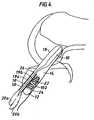
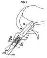
- Figs. 4 and 5 are sectional views illustrating alternative arrangements for the bone screw, sheath, and graft of Fig. 3 within the bone tunnel in the tibia;
- Fig. 6 is a perspective view of an alternative embodiment of the sheath of Fig. 2A;
- Fig. 7A is a perspective view of an alternative embodiment of the sheath of Fig. 2A that includes a washer;
- Fig. 7B is a top view of the washer of Fig. 7A;
- Fig. 8 is a perspective view of an alternative bone screw sheath that includes two tubes;
- Fig. 9 is a perspective view of a bone screw sheath according to the invention that includes four tubes arranged to form a ring; and
- Fig. 10 is a perspective view of the inventive bone screw sheath of Fig. 9 with an external sleeve.
- Embodiments of the invention feature sheaths that surround bone screws and soft tissue grafts to improve fixation of the grafts. In its simplest form not form, part of the present invention, the sheath is a flexible, mesh tube that surrounds only the bone screw, both the bone screw and the graft, or only the graft. In the inventive embodiments, the sheath includes multiple tubes as defined in claim 1.
- Referring to Figs. 2A-2C, a
sheath 50 has a tube-shaped body 52 that defines a generally cylindricalexterior surface 53 and a generallycylindrical interior 54.Body 52 is formed from a biocompatible material woven into a mesh structure. The mesh definesnumerous holes 56 that exposeinterior 54 to the outside. Sheath 50 also has two circular,open ends Interior 54 ofsheath 50 is sized and shaped to receivebone screw 12.Sheath 50 has an internal diameter D1 greater than the diameter DS ofbone screw 12, so that bothscrew 12 andsegments graft 10 can fit snugly within the sheath. The sheath has a length L1 slightly larger than the length LS ofscrew 12. Themesh body 52 is thin and flexible, allowing the sheath to adjust to fit snugly surround the screw;body 52 can be compressed to reduce the volume ofinterior 54, twisted, or stretched. Sincesheath 50 is thin and flexible rather than rigid, it cannot on its own shore up soft bone, or fix a graft within a bone tunnel. (i.e.,sheath 50 is not designed to be used alone as a fixation device or as a solid, rigid reinforcement of soft bone.)- In some embodiments, the threads forming the
mesh body 52 are larger in the radial direction than in the axial direction. This difference in thread size results insheath 50 being less flexible radially than axially. In these embodiments, the diameter D1 is more resistant to expansion or contraction than length L1. In other embodiments, the thread size is equal throughoutbody 52. - Diameter D1 is, e.g., between about 8 and 10 mm, and L1 is, between about 25 and 40 mm. If
sheath 50 is designed for a 7x25 bone screw (7 mm diameter, 25 mm length), then L1 is, e.g., about 30 mm, and D1 is, e.g., about 9 mm. Most ofexterior surface 53 is open. For example, about 40% of thearea exterior surface 53 is mesh strands, and about 60% is holes 56. The thickness T1 the mesh wall ofsheath 50 is, for example, less than about 0.3 mm, e.g., about 0.1-0.2 mm. Body 52 can be made from a variety of bioabsorbable materials, including polylactic acid, or polylactic glycolic acid. Alternatively,body 52 can be made from a blend of absorbable materials, or from a non-absorbable material, such as a polyester. The material forming the body preferably has a higher coefficient of friction thangraft 10, so thatexterior surface 53 of the sheath gripsinternal wall 24 ofbone tunnel 14 more firmly thangraft 10 alone, improving fixation.Body 52 can be formed, e.g., by weaving, braiding, knitting, or crocheting strands of the material to form the cylindrical shape, or by extrusion, using techniques known in the art. Thestrands forming body 52 have diameters of about 0.1-1.0 mm, e.g., 0.4-0.6 mm, or 0.51 mm.- Although
sheath 50 can be used with a variety of fixation screws, screw 12 preferably has blunt or rounded screw threads, as opposed to sharp threads, so that the threads do not cut the sheath or the soft tissue graft. A typical rounded-thread screw is shown inRoger et al., U.S. Patent No. 5,383,878 , which is incorporated herein by reference. - Referring to Fig. 3, in operation, a surgeon first forms
bone tunnels graft 10 is fixed to the femur tunnel using any technique known in the art (not shown). For example, the femur fixation device can include a loop attached to the femur at a distal end offemur tunnel 18.End 20a of the graft is passed distally throughtunnels tunnels graft 10 can be fixed within the femur tunnel, allowing the other end to extend proximally throughtunnels U.S. Patent No. 5,769,894 , which is incorporated herein by reference, and in Rosenberg,supra. - After attaching
graft 10 within (or adjacent to)femur tunnel 18, the surgeon passes ends 20a, 20b ofgraft 10 throughinterior 54 of sheath 50 (viaopen ends sheath 50 intotibial tunnel 14. The diameter oftunnel 14 is only slightly larger than the outer diameter ofsheath 50, such thatsheath 50 fits snugly withintunnel 14. Alternatively,sheath 50 can be inserted intotunnel 14 prior to passing the graft through the sheath. To insertsheath 50 intotibial tunnel 14, the surgeon can use a delivery tool, such as a rigid tube detachably fixed to the distal end of the sheath. Alternatively, a suture can be threaded through the distal end ofsheath 50, and the sheath can be pulled into place withintunnel 14 using the suture. - The surgeon then inserts
bone screw 12 intointerior 54 ofsheath 50, betweensegments screw 12 is in place as shown in Fig. 3, the screw pressessegments sheath 50, and pressesexterior surface 53 of the sheath againstwall 24, fixing the graft within the tunnel. - As shown in Fig. 3, when
screw 12 is inserted, it will typically be slightly of center, such that the screw's threads dig intowall 24 ofbone tunnel 14 along asegment 24a ofwall 24. For example, ifscrew 12 has a major diameter of 9 mm, and a minor diameter of 7 mm, then the screw threads will dig intowall 24 by about 1 mm alongsegment 24a, wheresegment 24a is about 120 degrees. This engagement of the threads withsegment 24a of the wall helps holdscrew 12 withintunnel 14, and therefore improves fixation ofgraft 10 within the tunnel. - The presence of
sheath 50 withinbone tunnel 14 improves fixation ofgraft 10. Sinceexterior surface 53 ofsheath 50 has a higher coefficient of fiction thangraft 10,sheath 50 is less likely than graft 10 (which is made of tissue) to slide alongwall 24 of the tunnel, or to twist whenscrew 12 is inserted into the tunnel. In addition, sincebody 52 ofsheath 50 has a mesh structure, portions ofgraft 10 protrude throughholes 56 of the mesh, resisting sliding ofgraft 10 relative tosheath 50. The flexibility ofsheath 50 allows the sheath to conform to the shape ofwall 24, maximizing the surface area contact between the exterior surface of the sheath andwall 24, thereby increasing frictional forces between the sheath and the wall. - After
screw 12 has been inserted intotunnel 14, the surgeon may trim the portions ofsegments tunnel 14, completing the surgical procedure. Over time,graft 10 permanently affixes to wall 24 by growth of Sharpy-like fibers between the soft tissue ofgraft 10 and the bone tissue ofwall 24. ("Sharpy-like fibers" are collagenous fibers that grow from bone into a soft tissue graft. The presence of Sharpy-like fibers indicate good bony growth to the graft, and therefore good fixation.SeePinczewski et al., "Integration of Hamstring Tendon Graft With Bone in Reconstruction of the Anterior Cruciate Ligament," Arthroscopy, 13: 641-43 (1997). Theopen holes 56 inbody 52 of the sheath facilitate permanent fixation by increasing the direct contact between the graft and the bone tunnel wall.Sheath 50 eventually dissolves, and new bone grows to fill its position. - To accelerate bone growth and permanent attachment of
graft 10 to wall 24,sheath 50 can include an osteoinductive agent, such as hydroxyapaptite, tricalcium phosphate, calcium sulphate, or a "ceramic" (a calcium and potassium crystalline). The osteoinductive agent can be applied tosheath 50 prior to surgery by, e.g., spraying the sheath with the agent, by dipping the sheath into a bath that includes the agent, by dusting or spraying the agent onto the sheath, or by filling the sheath with a gel that includes the agent. In addition, the strands of material forming themesh body 52 can be hollow, and the agent can be within the hollow interiors of the strands. Alternatively, the agent can be incorporated into the material that formsbody 52. For example, the agent can be blended into the material used to make the threads that formmesh body 52, or can be added to the fibers as an osteoinductive felt. - Other therapeutic agents, such as growth factors (e.g., tissue growth factor or platelet derived growth factor), bone morphogenic proteins, stem cells, osteoblasts, and cytokines, can also be included in the sheath. These bioactive agents can be added using the techniques described above, or can be blended into the material that forms
body 52 using micro-encapsulation or nanoparticles. For example,body 52 can be formed from a material comprising microspheres of the agent and a polymer, such as polylactic glycolic acid. The microspheres of the agent and polymer can be prepared using known techniques.See, e.g.,Cohen et al., "Controlled Delivery Systems for Proteins Based on Poly(Lactic/Glycolic Acid) Microspheres," Pharm. Research. 8:713-20 (1991);DeLuca et al., U.S. Patent Nos. 5,160,745 and4,741,872 . Rather than forming microspheres, the agent and polymer can also be mixed together using, e.g., sintering techniques.See,Cohen et al., "Sintering Techniques for the Preparation of Polymer Matrices for the Controlled Release of Macromolecules," J. Pharm. Sciences, 73:1034-37 (1984). The bioactive agents can also be attached tobody 52 using adhesives or electrical charge, or can be directly loaded onto the sheath by a delivery mechanism after implantation of the sheath. - Other embodiments are within the scope of the claims. For example, the sheath can be used to assist fixation of a bone screw within the
femur tunnel 18, in addition to thetibial tunnel 14. - Referring to Fig. 4, screw 12 can be placed between
sheath 50 andwall 24 oftunnel 14. In this embodiment, rather than insertingscrew 12 into the sheath after placement of the sheath withintunnel 14,screw 12 is inserted intotunnel 14 along the side of the sheath. To holdscrew 12 to the side of the sheath, the sheath can optionally include anexternal loop 102.Loop 102 has a diameter slightly larger than the diameter ofscrew 12, so thatshaft 22 ofscrew 12 fits snugly within the loop.Loop 102 can be made from the same material asbody 52, or can be made from an inflexible, rigid material. - When
screw 12 is inserted, it compressesgraft 10 within the sheath, and pressesexterior surface 53 of the sheath against,wall 24, fixinggraft 10 withintunnel 14. - Referring to Fig. 5,
segments graft 10 can be positioned radially outside ofsheath 50. In this embodiment, whensheath 50 is inserted intotunnel 14, it is located between ends 19a and 19b of the graft, so that the graft surrounds the sheath, rather than the sheath surrounding the graft.Screw 12 is then inserted into the sheath, pressingsegments exterior surface 53 of the sheath andwall 24, fixing the graph in place. Alternatively, the screw can first be inserted into the sheath, and then the sheath and screw together can be positioned within the bone tunnel. - The structure of the bone screw sheath can be modified as well. The diameter D1, length L1, and thickness T of the sheath can be varied to accommodate different sized bone tunnels, different sized screws, and different deployment methods. For example, in the deployment method of Fig. 5, the inner diameter D1 of the sheath can be approximately equal to the diameter DS of the screw shaft, so that the screw fits very snugly within the sheath, and
exterior surface 53 of the sheath conforms to the shape of the screw shaft. - In the deployment methods shown in Figs. 4 and 5, the sheath need not be more rigid in the radial direction than in the axial direction. The threads forming the mesh body, therefore, are generally the same size in both the radial and axial directions. In addition, sheaths used in the deployment method of Fig. 5 can have less open space than sheaths used with the method of Figs. 3 or 4. (I.e., less than 60% of the sheath's surface area will be holes.)
- If the bone is particularly soft,
sheath 50 can be woven tighter, so that the sheath is less flexible, thereby providing a more firm substrate forscrew 12 to engage. - The sheath need not have a mesh structure. For example, the sheath can have a solid body with holes cut through the body, allowing communication between the exterior and interior of the sheath. In addition, the sheath's body need not be integrally formed. For example, the body can be formed by winding a strip of material around an implantable device to form a relieved body that defines an interior.
- The sheath can have relief structures other than holes to allow communication between the exterior and interior. For example, other types of perforations, such as slits, can be used, instead of holes. In addition, the device can have a solid wall with thinned sections. When implanted, the thinned sections biodegrade more quickly than other sections of the wall, such thatin situ, the device develops perforations.
- To increase the coefficient of friction of
exterior surface 53 to improve fixation of the sheath within the bone tunnel,exterior surface 53 can have a roughened finish. - Referring to Fig. 6, rather than having two open circular ends,
sheath 150 has anopen end 158a and aclosed end 158b.Closed end 158b gives sheath a "bag" or "sock" shaped structure. - Referring to Fig. 7A, a
sheath 250 includes awasher 280 attached to theproximal end 282 of the sheath. Thewasher 280 has a diameter D2 that is larger than diameter D1 ofsheath 250, and is larger than the diameter of the bone tunnel.Washer 280 preventsproximal end 282 of the sheath from passing into the bone tunnel when the screw is inserted into the sheath, thereby ensuring that the sheath is ultimately positioned around the screw shaft, rather than in front of the screw. Rather than being circular, the washer can be square, triangular, or any other shape, so long as it has a dimension larger than the diameter of the bone tunnel. Referring to Fig. 7B, theupper surface 284 of the washer can include teeth orspikes 286 to grip bone, thereby reducing twisting ofsheath 250 when a bone screw is inserted into the sheath. The washer can be made from a bioabsorbable material, or a non-absorbable, biocompatible material. In operation, the washer can be detached from the sheath after implantation of the graft and bone screw, or can be left attached to the sheath. - Referring to Fig. 8, a
sheath 350 includes two contiguous, parallel mesh tubes, 352a and 352b.Tubes screw 12, and slightly less than diameter D1 ofsheath 50. Diameter D3 can be, e.g., 2 mm, 4 mm, 6 mm, or 8 mm.Sheath 50 has a length L3 approximately equal to the length of a fixation screw, e.g., about 10-50 mm, or 20-35 mm. Thewalls tubes - In operation, a soft tissue graft is passed through one of the tubes (e.g.,
tube 352a), and the fixation screw is inserted into the second tube (e.g.,tube 352b). When the sheath, graft, and fixation screw are positioned within the bone tunnel,tube 352a is compressed between the screw and a wall of the bone tunnel. The graft, therefore, is compressed withintube 352a, fixing the graft within the bone tunnel. - Referring to Fig. 9, a
sheath 450 includes four parallel mesh tubes, 452a, 452b, 452c, and 452d. The four tubes are arranged to form aring 454.Ring 454 defines acentral cavity 456 disposed between the tubes. The cavity defines an axial bore that is coextensive with the axial lengths of each of the tubes. - Each
tube sheath 350, the tubes ofsheath 450 are integrally woven. - In operation, segments of a soft tissue graft are passed through each of
tubes 452a-452d. The surgeon can either use multiple, independent tissue grafts separately attached to the femur tunnel, or can split the proximal end of a single graft into four separate segments. The sheath is then inserted into the tibial bone tunnel, and a fixation screw is inserted intocentral cavity 456. When the sheath, soft tissue, and screw are in place within the bone tunnel, the tubes are compressed between the screw and the bone tunnel wall, and the soft tissue segments are compressed within each tube, thereby fixing the soft tissue within the bone tunnel. - In the embodiment shown Fig. 9,
sheath 450 includes four tubes forming a ring. The sheath need not, however, be limited to this number. For example, the sheath can include a ring of 3, 5, 6, 7, or 8 tubes. In addition, soft tissue need not be passed through each tube. For example, soft tissue segments can be passed through two tubes, leaving the remaining tubes unoccupied. - Instead of being integrally woven, the tubes of
sheath 450 can be woven, braided, or knitted separately, and attached together using, e.g., stitching, spot welding, or an adhesive. The tubes can also be solid rather than mesh, and need not all have the same diameter. In addition, unlike the single tube sheaths of Figs. 2A, 6, and 7,sheath 450 can be rigid, rather than flexible. - Referring to Fig. 10,
sheath 550 is identical tosheath 450 in all respects, except thatsheath 550 further includes amesh sleeve 580 that surrounds the fourtubes 552a-552d.Sleeve 580 is axially coextensive withtubes 552a-552d, and is integrally woven with the four tubes. Alternatively,sleeve 580 can be a separate solid or mesh structure adhesively bound to the four tubes.Sleeve 580 acts to stabilizesheath 550, and facilitates insertion of the sheath into the bone tunnel. For example, to insertsheath 550, a suture or delivery tool can be attached tosleeve 580, rather than directly to one of the tubes. - The sheaths need not be used exclusively with bone screws or bone tunnels. Rather, the invention includes sheaths that improve fixation of other types of implantable fixation devices, such as soft tissue tacks, plugs, and suture anchors. The size and shapes of the sheaths can be varied to accommodate the different types of fixation devices. For example, in one embodiment, soft tissue can be positioned inside of a sheath, and the sheath can be attached to the side of a bone with a fixation device such as a tack.
Claims (17)
- A sheath (450) for an implantable fixation device comprising at least three generally parallel tubes (452)characterized in that the tubes are arranged side by side to form a ring (454), the ring defining a central cavity (456) between the tubes sized and shaped to receive the fixation device.
- The sheath of claim 1, wherein the central cavity includes a bore that is coextensive with the tubes.
- The sheath of claim 1, further comprising an external sleeve (580) surrounding the ring of tubes.
- The sheath of claim 1, wherein the ring of tubes includes exactly four tubes.
- The sheath of claim 1, wherein the tubes are flexible.
- The sheath of claim 1, wherein at least one of the tubes is sized and shaped to receive a portion of a soft tissue graft.
- The sheath of claim 6, wherein the tubes sized and shaped to receive a portion of the soft tissue graft are relieved.
- The sheath of claim 7, wherein the relieved tubes have a mesh structure.
- The sheath of claim 8, wherein each tube in the ring of tubes has a mesh structure, and the ring of tubes is integrally formed.
- The sheath according to any one of claims 1 to 9, wherein the tubes are made from a bioabsorbable material.
- The sheath according to any one of claims 1 to 10, wherein the tubes comprise a biocompatible material selected from the group consisting of hydroxyapetite, polylactic acid and polyglycolic acid.
- The sheath according to any one of claims 1 to 11, wherein the exterior of the tubes have a roughened exterior surface.
- The sheath according to any one of claims 1 to 12, further comprising a therapeutic agent.
- The sheath of claim 13, wherein the therapeutic agent Is an osteoinductive agent.
- The sheath of claim 13, wherein the therapeutic agent is a growth factor.
- The sheath of claim 13, wherein the therapeutic agent is disposed on at least a portion of an exterior surface of the tubes
- The sheath of claim 13, wherein the therapeutic agent is integrated into a material that forms the tubes.
Priority Applications (2)
| Application Number | Priority Date | Filing Date | Title |
|---|---|---|---|
| EP06021633AEP1752102B1 (en) | 2000-03-16 | 2001-03-14 | Sheaths for implantable fixation devices |
| EP10007318AEP2298182A1 (en) | 2000-03-16 | 2001-03-14 | Sheaths for implantable fixation devices |
Applications Claiming Priority (3)
| Application Number | Priority Date | Filing Date | Title |
|---|---|---|---|
| US526960 | 1995-09-13 | ||
| US09/526,960US6746483B1 (en) | 2000-03-16 | 2000-03-16 | Sheaths for implantable fixation devices |
| PCT/US2001/008124WO2001070135A2 (en) | 2000-03-16 | 2001-03-14 | Sheaths for implantable fixation devices |
Related Child Applications (1)
| Application Number | Title | Priority Date | Filing Date |
|---|---|---|---|
| EP06021633ADivisionEP1752102B1 (en) | 2000-03-16 | 2001-03-14 | Sheaths for implantable fixation devices |
Publications (3)
| Publication Number | Publication Date |
|---|---|
| EP1263329A2 EP1263329A2 (en) | 2002-12-11 |
| EP1263329B1 EP1263329B1 (en) | 2007-01-10 |
| EP1263329B9true EP1263329B9 (en) | 2007-06-27 |
Family
ID=24099528
Family Applications (3)
| Application Number | Title | Priority Date | Filing Date |
|---|---|---|---|
| EP01916648AExpired - LifetimeEP1263329B9 (en) | 2000-03-16 | 2001-03-14 | Sheaths for implantable fixation devices |
| EP06021633AExpired - LifetimeEP1752102B1 (en) | 2000-03-16 | 2001-03-14 | Sheaths for implantable fixation devices |
| EP10007318AWithdrawnEP2298182A1 (en) | 2000-03-16 | 2001-03-14 | Sheaths for implantable fixation devices |
Family Applications After (2)
| Application Number | Title | Priority Date | Filing Date |
|---|---|---|---|
| EP06021633AExpired - LifetimeEP1752102B1 (en) | 2000-03-16 | 2001-03-14 | Sheaths for implantable fixation devices |
| EP10007318AWithdrawnEP2298182A1 (en) | 2000-03-16 | 2001-03-14 | Sheaths for implantable fixation devices |
Country Status (8)
| Country | Link |
|---|---|
| US (8) | US6746483B1 (en) |
| EP (3) | EP1263329B9 (en) |
| JP (2) | JP4931317B2 (en) |
| AT (1) | ATE508691T1 (en) |
| AU (2) | AU4364601A (en) |
| CA (1) | CA2400630A1 (en) |
| DE (1) | DE60125916T2 (en) |
| WO (1) | WO2001070135A2 (en) |
Families Citing this family (184)
| Publication number | Priority date | Publication date | Assignee | Title |
|---|---|---|---|---|
| US6554862B2 (en)* | 1996-11-27 | 2003-04-29 | Ethicon, Inc. | Graft ligament anchor and method for attaching a graft ligament to a bone |
| US5899938A (en) | 1996-11-27 | 1999-05-04 | Joseph H. Sklar | Graft ligament anchor and method for attaching a graft ligament to a bone |
| US7083647B1 (en) | 1996-11-27 | 2006-08-01 | Sklar Joseph H | Fixation screw, graft ligament anchor assembly, and method for securing a graft ligament in a bone tunnel |
| US6746483B1 (en)* | 2000-03-16 | 2004-06-08 | Smith & Nephew, Inc. | Sheaths for implantable fixation devices |
| US7279008B2 (en)* | 2000-03-16 | 2007-10-09 | Smith & Nephew, Inc. | Sheaths for implantable fixation devices |
| US7556638B2 (en)* | 2000-05-26 | 2009-07-07 | Arthrex, Inc. | Retrograde fixation technique with insert-molded interference screw |
| US7195642B2 (en)* | 2001-03-13 | 2007-03-27 | Mckernan Daniel J | Method and apparatus for fixing a graft in a bone tunnel |
| US6887271B2 (en) | 2001-09-28 | 2005-05-03 | Ethicon, Inc. | Expanding ligament graft fixation system and method |
| EP1334702B1 (en)* | 2002-02-08 | 2004-07-07 | Karl Storz GmbH & Co. KG | Anchor element to anchor a ligament transplant |
| US20040153076A1 (en)* | 2002-10-29 | 2004-08-05 | Wamis Singhatat | Ligament graft cage fixation device |
| GB0227161D0 (en)* | 2002-11-21 | 2002-12-24 | Xiros Plc | Prosthetic implant assembly |
| WO2005000159A2 (en) | 2003-06-25 | 2005-01-06 | Baylor College Of Medicine | Tissue integration design for seamless implant fixation |
| US7309355B2 (en) | 2003-06-27 | 2007-12-18 | Depuy Mitek, Inc. | Flexible tibial sheath |
| US7326247B2 (en) | 2003-10-30 | 2008-02-05 | Arthrex, Inc. | Method for creating a double bundle ligament orientation in a single bone tunnel during knee ligament reconstruction |
| US20050159748A1 (en)* | 2003-12-19 | 2005-07-21 | Ron Clark | Compression bio-compatible fixation for soft tissue bone fixation |
| US7608092B1 (en) | 2004-02-20 | 2009-10-27 | Biomet Sports Medicince, LLC | Method and apparatus for performing meniscus repair |
| US20050278023A1 (en)* | 2004-06-10 | 2005-12-15 | Zwirkoski Paul A | Method and apparatus for filling a cavity |
| US8137382B2 (en) | 2004-11-05 | 2012-03-20 | Biomet Sports Medicine, Llc | Method and apparatus for coupling anatomical features |
| US8088130B2 (en) | 2006-02-03 | 2012-01-03 | Biomet Sports Medicine, Llc | Method and apparatus for coupling soft tissue to a bone |
| US7658751B2 (en) | 2006-09-29 | 2010-02-09 | Biomet Sports Medicine, Llc | Method for implanting soft tissue |
| US7909851B2 (en) | 2006-02-03 | 2011-03-22 | Biomet Sports Medicine, Llc | Soft tissue repair device and associated methods |
| US8840645B2 (en) | 2004-11-05 | 2014-09-23 | Biomet Sports Medicine, Llc | Method and apparatus for coupling soft tissue to a bone |
| US7857830B2 (en) | 2006-02-03 | 2010-12-28 | Biomet Sports Medicine, Llc | Soft tissue repair and conduit device |
| US8128658B2 (en) | 2004-11-05 | 2012-03-06 | Biomet Sports Medicine, Llc | Method and apparatus for coupling soft tissue to bone |
| US7905903B2 (en) | 2006-02-03 | 2011-03-15 | Biomet Sports Medicine, Llc | Method for tissue fixation |
| US8303604B2 (en) | 2004-11-05 | 2012-11-06 | Biomet Sports Medicine, Llc | Soft tissue repair device and method |
| US7749250B2 (en) | 2006-02-03 | 2010-07-06 | Biomet Sports Medicine, Llc | Soft tissue repair assembly and associated method |
| US8118836B2 (en) | 2004-11-05 | 2012-02-21 | Biomet Sports Medicine, Llc | Method and apparatus for coupling soft tissue to a bone |
| US7905904B2 (en) | 2006-02-03 | 2011-03-15 | Biomet Sports Medicine, Llc | Soft tissue repair device and associated methods |
| US20060189993A1 (en) | 2004-11-09 | 2006-08-24 | Arthrotek, Inc. | Soft tissue conduit device |
| US9801708B2 (en) | 2004-11-05 | 2017-10-31 | Biomet Sports Medicine, Llc | Method and apparatus for coupling soft tissue to a bone |
| US9017381B2 (en) | 2007-04-10 | 2015-04-28 | Biomet Sports Medicine, Llc | Adjustable knotless loops |
| US8361113B2 (en) | 2006-02-03 | 2013-01-29 | Biomet Sports Medicine, Llc | Method and apparatus for coupling soft tissue to a bone |
| US8298262B2 (en) | 2006-02-03 | 2012-10-30 | Biomet Sports Medicine, Llc | Method for tissue fixation |
| US7608098B1 (en) | 2004-11-09 | 2009-10-27 | Biomet Sports Medicine, Llc | Bone fixation device |
| US8034090B2 (en) | 2004-11-09 | 2011-10-11 | Biomet Sports Medicine, Llc | Tissue fixation device |
| US7914539B2 (en) | 2004-11-09 | 2011-03-29 | Biomet Sports Medicine, Llc | Tissue fixation device |
| US8998949B2 (en) | 2004-11-09 | 2015-04-07 | Biomet Sports Medicine, Llc | Soft tissue conduit device |
| CN101170966A (en)* | 2005-04-01 | 2008-04-30 | 科罗拉多州立大学董事会 | Graft fixation devices and methods |
| CN103251449B (en)* | 2005-10-13 | 2016-03-02 | 斯恩蒂斯有限公司 | Drug-impregnated encasement |
| WO2007070024A2 (en)* | 2005-12-09 | 2007-06-21 | Spinal Ventures, Inc. | Non-soft tissue repair |
| US8652172B2 (en) | 2006-02-03 | 2014-02-18 | Biomet Sports Medicine, Llc | Flexible anchors for tissue fixation |
| US8562645B2 (en) | 2006-09-29 | 2013-10-22 | Biomet Sports Medicine, Llc | Method and apparatus for forming a self-locking adjustable loop |
| US7959650B2 (en) | 2006-09-29 | 2011-06-14 | Biomet Sports Medicine, Llc | Adjustable knotless loops |
| US9271713B2 (en) | 2006-02-03 | 2016-03-01 | Biomet Sports Medicine, Llc | Method and apparatus for tensioning a suture |
| US10517587B2 (en) | 2006-02-03 | 2019-12-31 | Biomet Sports Medicine, Llc | Method and apparatus for forming a self-locking adjustable loop |
| US8597327B2 (en) | 2006-02-03 | 2013-12-03 | Biomet Manufacturing, Llc | Method and apparatus for sternal closure |
| US8506597B2 (en) | 2011-10-25 | 2013-08-13 | Biomet Sports Medicine, Llc | Method and apparatus for interosseous membrane reconstruction |
| US8251998B2 (en) | 2006-08-16 | 2012-08-28 | Biomet Sports Medicine, Llc | Chondral defect repair |
| US9078644B2 (en) | 2006-09-29 | 2015-07-14 | Biomet Sports Medicine, Llc | Fracture fixation device |
| US8652171B2 (en) | 2006-02-03 | 2014-02-18 | Biomet Sports Medicine, Llc | Method and apparatus for soft tissue fixation |
| US8562647B2 (en) | 2006-09-29 | 2013-10-22 | Biomet Sports Medicine, Llc | Method and apparatus for securing soft tissue to bone |
| US8574235B2 (en) | 2006-02-03 | 2013-11-05 | Biomet Sports Medicine, Llc | Method for trochanteric reattachment |
| US9468433B2 (en) | 2006-02-03 | 2016-10-18 | Biomet Sports Medicine, Llc | Method and apparatus for forming a self-locking adjustable loop |
| US9538998B2 (en) | 2006-02-03 | 2017-01-10 | Biomet Sports Medicine, Llc | Method and apparatus for fracture fixation |
| US9149267B2 (en) | 2006-02-03 | 2015-10-06 | Biomet Sports Medicine, Llc | Method and apparatus for coupling soft tissue to a bone |
| US11259792B2 (en) | 2006-02-03 | 2022-03-01 | Biomet Sports Medicine, Llc | Method and apparatus for coupling anatomical features |
| US8801783B2 (en) | 2006-09-29 | 2014-08-12 | Biomet Sports Medicine, Llc | Prosthetic ligament system for knee joint |
| US8771352B2 (en) | 2011-05-17 | 2014-07-08 | Biomet Sports Medicine, Llc | Method and apparatus for tibial fixation of an ACL graft |
| US8968364B2 (en) | 2006-02-03 | 2015-03-03 | Biomet Sports Medicine, Llc | Method and apparatus for fixation of an ACL graft |
| US11311287B2 (en) | 2006-02-03 | 2022-04-26 | Biomet Sports Medicine, Llc | Method for tissue fixation |
| US20070250114A1 (en)* | 2006-04-20 | 2007-10-25 | Sdgi Holdings, Inc. | Flexible tissue sheath for fibrous connective tissue repair |
| US9918826B2 (en) | 2006-09-29 | 2018-03-20 | Biomet Sports Medicine, Llc | Scaffold for spring ligament repair |
| US8500818B2 (en) | 2006-09-29 | 2013-08-06 | Biomet Manufacturing, Llc | Knee prosthesis assembly with ligament link |
| US11259794B2 (en) | 2006-09-29 | 2022-03-01 | Biomet Sports Medicine, Llc | Method for implanting soft tissue |
| US8226714B2 (en)* | 2006-09-29 | 2012-07-24 | Depuy Mitek, Inc. | Femoral fixation |
| US8672969B2 (en) | 2006-09-29 | 2014-03-18 | Biomet Sports Medicine, Llc | Fracture fixation device |
| US8753391B2 (en)* | 2007-02-12 | 2014-06-17 | The Trustees Of Columbia University In The City Of New York | Fully synthetic implantable multi-phased scaffold |
| US8795194B2 (en) | 2007-03-30 | 2014-08-05 | Smith & Nephew, Inc. | Tissue harvesting |
| GB0710023D0 (en)* | 2007-05-25 | 2007-07-04 | Facilities Council | Graft fixation device |
| JP6017759B2 (en)* | 2007-12-21 | 2016-11-02 | スミス アンド ネフュー インコーポレーテッドSmith & Nephew,Inc. | Cannula |
| JP5283377B2 (en)* | 2007-12-26 | 2013-09-04 | 株式会社ハイレックスコーポレーション | Ligament or tendon anchor, graft ligament set using the same, and ligament transplantation method using the same |
| US20090193338A1 (en) | 2008-01-28 | 2009-07-30 | Trevor Fiatal | Reducing network and battery consumption during content delivery and playback |
| AU2008349523B2 (en)* | 2008-01-29 | 2013-10-24 | Zimmer, Inc. | Implant device for use in an implant system |
| EP2259749A1 (en)* | 2008-03-13 | 2010-12-15 | Tavor (I.T.N) Ltd. | Ligament and tendon prosthesis |
| EP2306913A4 (en)* | 2008-03-28 | 2014-06-04 | Warsaw Orthopedic Inc | Bone anchors for orthopedic applications |
| US20090275945A1 (en)* | 2008-04-30 | 2009-11-05 | Exploramed Nc4, Inc. | Sheaths for extra-articular implantable systems |
| US20090281581A1 (en) | 2008-05-06 | 2009-11-12 | Berg Jeffery H | Method and device for securing sutures to bones |
| KR20110033199A (en)* | 2008-06-19 | 2011-03-30 | 신세스 게엠바하 | Bone Screw Percussion Augmented Implants, Systems and Technologies |
| US12419632B2 (en) | 2008-08-22 | 2025-09-23 | Biomet Sports Medicine, Llc | Method and apparatus for coupling anatomical features |
| US12245759B2 (en) | 2008-08-22 | 2025-03-11 | Biomet Sports Medicine, Llc | Method and apparatus for coupling soft tissue to bone |
| US9011533B2 (en)* | 2008-10-13 | 2015-04-21 | The General Hospital Corporation | Single tunnel, double bundle anterior cruciate ligament reconstruction using bone-patellar tendon-bone grafts |
| US20100121355A1 (en) | 2008-10-24 | 2010-05-13 | The Foundry, Llc | Methods and devices for suture anchor delivery |
| US8858634B2 (en) | 2008-11-04 | 2014-10-14 | Mayo Foundation For Medical Education And Research | Soft tissue attachment device |
| EP2349089A4 (en)* | 2008-11-21 | 2014-01-15 | Lifecell Corp | Reinforced biologic material |
| US8845725B2 (en)* | 2009-04-17 | 2014-09-30 | Lumaca Orthopaedics Pty Ltd | Tenodesis system |
| US20100292733A1 (en) | 2009-05-12 | 2010-11-18 | Foundry Newco Xi, Inc. | Knotless suture anchor and methods of use |
| WO2010132310A1 (en) | 2009-05-12 | 2010-11-18 | Foundry Newco Xi, Inc. | Methods and devices to treat diseased or injured musculoskeletal tissue |
| US8343227B2 (en) | 2009-05-28 | 2013-01-01 | Biomet Manufacturing Corp. | Knee prosthesis assembly with ligament link |
| US12096928B2 (en) | 2009-05-29 | 2024-09-24 | Biomet Sports Medicine, Llc | Method and apparatus for coupling soft tissue to a bone |
| US8460350B2 (en)* | 2009-06-19 | 2013-06-11 | Arthrex, Inc. | Graft protection mesh and fixation technique |
| US9364276B2 (en) | 2009-07-09 | 2016-06-14 | Smith & Nephew, Inc | Tissue graft anchor assembly and instrumentation for use therewith |
| AU2010271431B2 (en) | 2009-07-09 | 2015-12-24 | Smith & Nephew, Inc. | Tissue graft anchor assembly and instrumentation for use therewith |
| US8828053B2 (en) | 2009-07-24 | 2014-09-09 | Depuy Mitek, Llc | Methods and devices for repairing and anchoring damaged tissue |
| US8814903B2 (en)* | 2009-07-24 | 2014-08-26 | Depuy Mitek, Llc | Methods and devices for repairing meniscal tissue |
| US20120029578A1 (en)* | 2010-02-05 | 2012-02-02 | Sean Suh | Bio-Resorbable Capsule Containing Fenestrated Screw System For Osteoporotic Subject |
| KR101151358B1 (en)* | 2010-03-17 | 2012-06-08 | 동국대학교 산학협력단 | Composite Scaffold Containing Silk and Collagen and Preparation Method Thereof |
| CA2797607A1 (en) | 2010-04-27 | 2011-11-03 | Synthes Usa, Llc | Anchor assembly including expandable anchor |
| US9597064B2 (en) | 2010-04-27 | 2017-03-21 | DePuy Synthes Products, Inc. | Methods for approximating a tissue defect using an anchor assembly |
| US9451938B2 (en) | 2010-04-27 | 2016-09-27 | DePuy Synthes Products, Inc. | Insertion instrument for anchor assembly |
| US9743919B2 (en) | 2010-04-27 | 2017-08-29 | DePuy Synthes Products, Inc. | Stitch lock for attaching two or more structures |
| US8858577B2 (en) | 2010-05-19 | 2014-10-14 | University Of Utah Research Foundation | Tissue stabilization system |
| US8945156B2 (en) | 2010-05-19 | 2015-02-03 | University Of Utah Research Foundation | Tissue fixation |
| WO2011160166A1 (en)* | 2010-06-22 | 2011-12-29 | Peter Michael Sutherland Walker | Ligament retainer device and method |
| CH703627B1 (en)* | 2010-08-25 | 2014-12-15 | Arnold Schefer | Anchor sleeve. |
| US9724188B2 (en) | 2010-10-27 | 2017-08-08 | The General Hospital Corporation | System and method for ligament reconstruction |
| US8852214B2 (en) | 2011-02-04 | 2014-10-07 | University Of Utah Research Foundation | System for tissue fixation to bone |
| US9427493B2 (en) | 2011-03-07 | 2016-08-30 | The Regents Of The University Of Colorado | Shape memory polymer intraocular lenses |
| US12329373B2 (en) | 2011-05-02 | 2025-06-17 | Biomet Sports Medicine, Llc | Method and apparatus for soft tissue fixation |
| US20140222088A1 (en)* | 2011-05-08 | 2014-08-07 | Spinal Ventures, Llc | Implant and Fastener Fixation Devices and Delivery Instrumentation |
| WO2013010283A2 (en)* | 2011-07-18 | 2013-01-24 | Sportwelding Gmbh | Method of fastening a soft tissue graft in an opening provided in a human or animal bone and fastener suitable for the method |
| US8556970B2 (en)* | 2011-09-28 | 2013-10-15 | Depuy Mitek, Llc | Graft introducer |
| US9357991B2 (en) | 2011-11-03 | 2016-06-07 | Biomet Sports Medicine, Llc | Method and apparatus for stitching tendons |
| US9314241B2 (en) | 2011-11-10 | 2016-04-19 | Biomet Sports Medicine, Llc | Apparatus for coupling soft tissue to a bone |
| US9370350B2 (en) | 2011-11-10 | 2016-06-21 | Biomet Sports Medicine, Llc | Apparatus for coupling soft tissue to a bone |
| US9381013B2 (en) | 2011-11-10 | 2016-07-05 | Biomet Sports Medicine, Llc | Method for coupling soft tissue to a bone |
| CN116746973A (en) | 2011-11-14 | 2023-09-15 | 亚瑟罗凯尔公司 | Tissue repair assembly |
| TWI590843B (en) | 2011-12-28 | 2017-07-11 | 信迪思有限公司 | Films and methods of manufacture |
| US9259217B2 (en) | 2012-01-03 | 2016-02-16 | Biomet Manufacturing, Llc | Suture Button |
| US8926662B2 (en) | 2012-02-01 | 2015-01-06 | Smith & Nephew, Inc. | Tissue graft anchoring |
| US9204959B2 (en)* | 2012-02-02 | 2015-12-08 | Smith & Nephew, Inc. | Implantable biologic holder |
| CN104994809A (en)* | 2012-03-23 | 2015-10-21 | 匹兹堡大学联邦制高等教育 | Tissue graft anchoring |
| US9427309B2 (en) | 2012-07-30 | 2016-08-30 | Conextions, Inc. | Soft tissue repair devices, systems, and methods |
| US10390935B2 (en) | 2012-07-30 | 2019-08-27 | Conextions, Inc. | Soft tissue to bone repair devices, systems, and methods |
| US10219804B2 (en) | 2012-07-30 | 2019-03-05 | Conextions, Inc. | Devices, systems, and methods for repairing soft tissue and attaching soft tissue to bone |
| US10835241B2 (en) | 2012-07-30 | 2020-11-17 | Conextions, Inc. | Devices, systems, and methods for repairing soft tissue and attaching soft tissue to bone |
| US11944531B2 (en) | 2012-07-30 | 2024-04-02 | Conextions, Inc. | Devices, systems, and methods for repairing soft tissue and attaching soft tissue to bone |
| US11253252B2 (en) | 2012-07-30 | 2022-02-22 | Conextions, Inc. | Devices, systems, and methods for repairing soft tissue and attaching soft tissue to bone |
| US11957334B2 (en) | 2012-07-30 | 2024-04-16 | Conextions, Inc. | Devices, systems, and methods for repairing soft tissue and attaching soft tissue to bone |
| US9232939B2 (en) | 2012-09-11 | 2016-01-12 | Biomet Sports Medicine, Llc | Flexible planar member for tissue fixation |
| US20140088647A1 (en)* | 2012-09-21 | 2014-03-27 | Atlas Spine, Inc. | Minimally invasive spine surgery instruments: spinal rod with flange |
| US9757119B2 (en) | 2013-03-08 | 2017-09-12 | Biomet Sports Medicine, Llc | Visual aid for identifying suture limbs arthroscopically |
| US9974643B2 (en) | 2013-03-11 | 2018-05-22 | Medos International Sàrl | Implant having adjustable filament coils |
| US10052094B2 (en) | 2013-03-11 | 2018-08-21 | Medos International Sàrl | Implant having adjustable filament coils |
| US10182806B2 (en) | 2013-03-12 | 2019-01-22 | Arthrocare Corporation | Tissue repair assembly |
| US9918827B2 (en) | 2013-03-14 | 2018-03-20 | Biomet Sports Medicine, Llc | Scaffold for spring ligament repair |
| KR102391275B1 (en) | 2013-03-14 | 2022-04-27 | 케이에프엑스 메디컬, 엘엘씨 | Tissue capturing bone anchor |
| US20140277449A1 (en)* | 2013-03-15 | 2014-09-18 | Woven Orthopedic Technologies, LLC. | Bone screw and tendon fixation enhancement devices and methods |
| US9585695B2 (en) | 2013-03-15 | 2017-03-07 | Woven Orthopedic Technologies, Llc | Surgical screw hole liner devices and related methods |
| CA2904717C (en)* | 2013-03-15 | 2021-05-11 | Malcolm Heaven | System and method for securing tissue to bone |
| WO2014169058A1 (en)* | 2013-04-09 | 2014-10-16 | Smith & Nephew, Inc | Open-architecture interference screw |
| US20160100934A1 (en)* | 2013-05-24 | 2016-04-14 | Northeastern University | Nanomaterials for the integration of soft into hard tissue |
| US20160144067A1 (en) | 2013-06-21 | 2016-05-26 | DePuy Synthes Products, Inc. | Films and methods of manufacture |
| US9757113B2 (en) | 2013-07-31 | 2017-09-12 | Medos International Sàrl | Adjustable graft fixation device |
| US10405968B2 (en) | 2013-12-11 | 2019-09-10 | Medos International Sarl | Implant having filament limbs of an adjustable loop disposed in a shuttle suture |
| US10136886B2 (en) | 2013-12-20 | 2018-11-27 | Biomet Sports Medicine, Llc | Knotless soft tissue devices and techniques |
| US9962150B2 (en) | 2013-12-20 | 2018-05-08 | Arthrocare Corporation | Knotless all suture tissue repair |
| US11583384B2 (en) | 2014-03-12 | 2023-02-21 | Conextions, Inc. | Devices, systems, and methods for repairing soft tissue and attaching soft tissue to bone |
| WO2015138760A1 (en) | 2014-03-12 | 2015-09-17 | Conextions, Inc. | Soft tissue repair devices, systems, and methods |
| US9615822B2 (en) | 2014-05-30 | 2017-04-11 | Biomet Sports Medicine, Llc | Insertion tools and method for soft anchor |
| US9700291B2 (en) | 2014-06-03 | 2017-07-11 | Biomet Sports Medicine, Llc | Capsule retractor |
| US8956394B1 (en) | 2014-08-05 | 2015-02-17 | Woven Orthopedic Technologies, Llc | Woven retention devices, systems and methods |
| US9907593B2 (en) | 2014-08-05 | 2018-03-06 | Woven Orthopedic Technologies, Llc | Woven retention devices, systems and methods |
| US10039543B2 (en) | 2014-08-22 | 2018-08-07 | Biomet Sports Medicine, Llc | Non-sliding soft anchor |
| US9943351B2 (en) | 2014-09-16 | 2018-04-17 | Woven Orthopedic Technologies, Llc | Woven retention devices, systems, packaging, and related methods |
| USD740427S1 (en) | 2014-10-17 | 2015-10-06 | Woven Orthopedic Technologies, Llc | Orthopedic woven retention device |
| US9955980B2 (en) | 2015-02-24 | 2018-05-01 | Biomet Sports Medicine, Llc | Anatomic soft tissue repair |
| US9974534B2 (en) | 2015-03-31 | 2018-05-22 | Biomet Sports Medicine, Llc | Suture anchor with soft anchor of electrospun fibers |
| US10973621B2 (en) | 2015-07-31 | 2021-04-13 | Arthrex, Inc. | Graft compression and sizing tubes |
| US10555758B2 (en)* | 2015-08-05 | 2020-02-11 | Woven Orthopedic Technologies, Llc | Tapping devices, systems and methods for use in bone tissue |
| US20170035481A1 (en)* | 2015-08-05 | 2017-02-09 | Woven Orthopedic Technologies, Llc | Devices, systems and methods for use in bone tissue |
| US20180228596A1 (en)* | 2015-08-14 | 2018-08-16 | Douglas J. Wyland | Device, Kit and Surgical Method Including Sleeve |
| US9931196B2 (en)* | 2015-08-26 | 2018-04-03 | Albert Einstein Healthcare Network | Connector for attaching tissue to bone |
| WO2017035563A1 (en)* | 2015-09-02 | 2017-03-09 | Maxm Medical Pty Ltd | A tibial anchor arrangement for a short surgical graft used in anterior cruciate ligament knee joint reconstruction |
| US10596660B2 (en) | 2015-12-15 | 2020-03-24 | Howmedica Osteonics Corp. | Porous structures produced by additive layer manufacturing |
| KR101822588B1 (en)* | 2016-03-28 | 2018-02-27 | 연세대학교 산학협력단 | Tube member and implant apparatus comprising the same |
| US10524837B2 (en)* | 2016-07-26 | 2020-01-07 | Arthrex, Inc. | Three dimensional spacer fabric to increase the holding power of screws |
| US10828146B2 (en) | 2016-08-04 | 2020-11-10 | Stryker Corporation | Instrumentation for soft tissue reconstruction |
| US11696822B2 (en) | 2016-09-28 | 2023-07-11 | Conextions, Inc. | Devices, systems, and methods for repairing soft tissue and attaching soft tissue to bone |
| WO2018107114A1 (en)* | 2016-12-09 | 2018-06-14 | Woven Orthopedic Technologies, LLC. | Retention devices, lattices and related systems and methods |
| US10368857B2 (en) | 2017-03-13 | 2019-08-06 | Medos International Sarl | Methods and devices for knotless suture anchoring |
| US10245020B2 (en) | 2017-03-13 | 2019-04-02 | Medos International Sarl | Methods and systems for knotless suture anchoring |
| US11628517B2 (en) | 2017-06-15 | 2023-04-18 | Howmedica Osteonics Corp. | Porous structures produced by additive layer manufacturing |
| EP3479798B1 (en) | 2017-11-03 | 2023-06-21 | Howmedica Osteonics Corp. | Flexible construct for femoral reconstruction |
| US10912867B2 (en)* | 2017-11-15 | 2021-02-09 | De Novo Orthopedics Inc. | Bioinductive patch |
| US11547397B2 (en) | 2017-12-20 | 2023-01-10 | Conextions, Inc. | Devices, systems, and methods for repairing soft tissue and attaching soft tissue to bone |
| US12102317B2 (en) | 2017-12-20 | 2024-10-01 | Conextions, Inc. | Devices, systems, and methods for repairing soft tissue and attaching soft tissue to bone |
| US10973509B2 (en) | 2017-12-20 | 2021-04-13 | Conextions, Inc. | Devices, systems, and methods for repairing soft tissue and attaching soft tissue to bone |
| WO2020197973A1 (en)* | 2019-03-22 | 2020-10-01 | Douglas J Wyland M D | Fibrous connective tissue protective device, method of manufacturing, and surgical method |
| US11883243B2 (en) | 2019-10-31 | 2024-01-30 | Orthopediatrics Corp. | Assessment of tension between bone anchors |
| US11903620B2 (en)* | 2021-01-25 | 2024-02-20 | Medos International Sarl | Flexible sleeve for bone fixation, and related systems and methods |
| CN113974730B (en)* | 2021-12-30 | 2022-04-22 | 杭州锐健马斯汀医疗器材有限公司 | Fixing system |
| WO2023212004A1 (en)* | 2022-04-27 | 2023-11-02 | Aesclepius Corporation | Systems, devices, and methods for bone suture attachment and support |
| DE102022127583A1 (en)* | 2022-10-19 | 2024-04-25 | Karl Storz Se & Co. Kg | Support device for an implantable thread construction, system and measuring method with such a support device and manufacturing method for a support device |
Family Cites Families (71)
| Publication number | Priority date | Publication date | Assignee | Title |
|---|---|---|---|---|
| DE1107898B (en) | 1957-03-07 | 1961-05-31 | Buchler & Co | Applicator for irradiating the parametria and portio mucosa |
| US3921498A (en)* | 1974-05-24 | 1975-11-25 | Us Navy | Fin clip and connector mount |
| US3921496A (en)* | 1974-11-04 | 1975-11-25 | J Frank Helderman | Fastener assembly |
| US4469101A (en) | 1980-10-23 | 1984-09-04 | Battelle Memorial Institute | Suture device |
| US4605414A (en)* | 1984-06-06 | 1986-08-12 | John Czajka | Reconstruction of a cruciate ligament |
| DE3445738A1 (en)* | 1984-12-14 | 1986-06-19 | Draenert Klaus | IMPLANT FOR BONE REINFORCEMENT AND ANCHORING OF BONE SCREWS, IMPLANTS OR IMPLANT PARTS |
| US4731084A (en) | 1986-03-14 | 1988-03-15 | Richards Medical Company | Prosthetic ligament |
| US5160745A (en) | 1986-05-16 | 1992-11-03 | The University Of Kentucky Research Foundation | Biodegradable microspheres as a carrier for macromolecules |
| US4741872A (en) | 1986-05-16 | 1988-05-03 | The University Of Kentucky Research Foundation | Preparation of biodegradable microspheres useful as carriers for macromolecules |
| EP0280572A1 (en) | 1987-02-27 | 1988-08-31 | Synthes Ag Chur | Tension isometer |
| DE3814815A1 (en)* | 1988-05-02 | 1989-11-16 | Fischer Artur Werke Gmbh | SPREADING DOWEL FOR MEDICAL APPLICATIONS |
| US5702371A (en)* | 1989-07-24 | 1997-12-30 | Venetec International, Inc. | Tube fitting anchoring system |
| US5290558A (en) | 1989-09-21 | 1994-03-01 | Osteotech, Inc. | Flowable demineralized bone powder composition and its use in bone repair |
| US5139520A (en) | 1990-01-31 | 1992-08-18 | American Cyanamid Company | Method for acl reconstruction |
| ATE159163T1 (en)* | 1990-09-04 | 1997-11-15 | Hip Dev Pty Ltd | SURGICAL SCREW |
| US7074203B1 (en)* | 1990-09-25 | 2006-07-11 | Depuy Mitek, Inc. | Bone anchor and deployment device therefor |
| US5152790A (en)* | 1991-03-21 | 1992-10-06 | American Cyanamid Company | Ligament reconstruction graft anchor apparatus |
| US5071420A (en)* | 1991-04-25 | 1991-12-10 | Depuy Du Pont Orthopaedics | Isometry testing device |
| FR2678823B1 (en) | 1991-07-11 | 1995-07-07 | Legrand Jean Jacques | DEVICE FOR REINFORCING A LIGAMENT DURING A LIGAMENT PLASTY. |
| US5197976A (en) | 1991-09-16 | 1993-03-30 | Atrium Medical Corporation | Manually separable multi-lumen vascular graft |
| US5211647A (en) | 1992-02-19 | 1993-05-18 | Arthrex Inc. | Interference screw and cannulated sheath for endosteal fixation of ligaments |
| US5380334A (en)* | 1993-02-17 | 1995-01-10 | Smith & Nephew Dyonics, Inc. | Soft tissue anchors and systems for implantation |
| US5632748A (en) | 1993-06-14 | 1997-05-27 | Linvatec Corporation | Endosteal anchoring device for urging a ligament against a bone surface |
| EP0642773B1 (en)* | 1993-09-14 | 2003-05-28 | Lanny L. Johnson | Biological replacement ligament |
| CA2109493A1 (en)* | 1993-10-28 | 1995-04-29 | Laurie Kutzner | Hair band with removable cover |
| FR2714817B1 (en) | 1994-01-12 | 1996-03-08 | Franck Baudry | Semi-artificial prosthetic ligament. |
| US5456685A (en) | 1994-02-14 | 1995-10-10 | Smith & Nephew Dyonics, Inc. | Interference screw having a tapered back root |
| US5641256A (en) | 1994-06-09 | 1997-06-24 | Npc, Inc. | Anchoring device for a threaded member |
| US5490750A (en) | 1994-06-09 | 1996-02-13 | Gundy; William P. | Anchoring device for a threaded member |
| US5671695A (en)* | 1994-07-28 | 1997-09-30 | Depuy Inc. | Replacement ligament graft passer and method |
| US5765682A (en)* | 1994-10-13 | 1998-06-16 | Menlo Care, Inc. | Restrictive package for expandable or shape memory medical devices and method of preventing premature change of same |
| JP3689146B2 (en) | 1995-05-30 | 2005-08-31 | ペンタックス株式会社 | Elements for screw fixation to bone |
| EP0910287B1 (en) | 1995-06-06 | 2007-12-19 | Raymond Thal | Knotless suture anchor assembly |
| US5569306A (en) | 1995-06-06 | 1996-10-29 | Thal; Raymond | Knotless suture anchor assembly |
| FR2745710B1 (en)* | 1996-03-11 | 1998-05-29 | Rippstein Pascal Francois | TENDON PASSING DEVICE |
| JPH1014936A (en)* | 1996-07-05 | 1998-01-20 | Homuzu Giken:Kk | Bone joint fastener |
| US5632784A (en)* | 1996-08-07 | 1997-05-27 | Daewoo Electronics, Co., Ltd. | Method of manufacturing a lithium battery |
| US6254628B1 (en)* | 1996-12-09 | 2001-07-03 | Micro Therapeutics, Inc. | Intracranial stent |
| AU5407598A (en) | 1996-11-15 | 1998-06-10 | Medisolve Ltd. | Bone implant |
| US6533816B2 (en) | 1999-02-09 | 2003-03-18 | Joseph H. Sklar | Graft ligament anchor and method for attaching a graft ligament to a bone |
| US5899938A (en) | 1996-11-27 | 1999-05-04 | Joseph H. Sklar | Graft ligament anchor and method for attaching a graft ligament to a bone |
| US5769894A (en) | 1997-02-05 | 1998-06-23 | Smith & Nephew, Inc. | Graft attachment device and method of attachment |
| US5713904A (en) | 1997-02-12 | 1998-02-03 | Third Millennium Engineering, Llc | Selectively expandable sacral fixation screw-sleeve device |
| US5918604A (en)* | 1997-02-12 | 1999-07-06 | Arthrex, Inc. | Method of loading tendons into the knee |
| AUPO530997A0 (en)* | 1997-02-25 | 1997-03-20 | Esnouf, Philip Stuart | Surgical aid for connective tissue grafting and method for employing same |
| US5935129A (en)* | 1997-03-07 | 1999-08-10 | Innovasive Devices, Inc. | Methods and apparatus for anchoring objects to bone |
| DE69826688T2 (en) | 1997-07-03 | 2005-11-17 | Ethicon, Inc. | DEVICE FOR ANCHORING BODY-FREE OR ARTIFICIAL TENANTS IN BONES |
| EP0893109B1 (en) | 1997-07-23 | 2005-03-02 | Arthrotek, Inc. | Apparatus for tibial fixation of soft tissue |
| US5906632A (en)* | 1997-10-03 | 1999-05-25 | Innovasive Devices, Inc. | Intratunnel attachment device and system for a flexible load-bearing structure and method of use |
| US6415373B1 (en)* | 1997-12-24 | 2002-07-02 | Avid Technology, Inc. | Computer system and process for transferring multiple high bandwidth streams of data between multiple storage units and multiple applications in a scalable and reliable manner |
| US6454808B1 (en) | 1998-01-28 | 2002-09-24 | M-E-System Inc. | Finger joint prosthesis |
| US5984926A (en)* | 1998-02-24 | 1999-11-16 | Jones; A. Alexander M. | Bone screw shimming and bone graft containment system and method |
| US5964764A (en) | 1998-03-24 | 1999-10-12 | Hugh S. West, Jr. | Apparatus and methods for mounting a ligament graft to a bone |
| CA2360168C (en) | 1999-02-01 | 2008-10-14 | Hideki Hyodoh | Woven bifurcated and trifurcated stents and methods for making the same |
| US6203572B1 (en) | 1999-02-09 | 2001-03-20 | Linvatec Corporation | Device and method for ligament reconstruction |
| AU772581B2 (en)* | 1999-08-06 | 2004-04-29 | Isotis N.V. | Fixative device |
| US7279008B2 (en) | 2000-03-16 | 2007-10-09 | Smith & Nephew, Inc. | Sheaths for implantable fixation devices |
| US6746483B1 (en) | 2000-03-16 | 2004-06-08 | Smith & Nephew, Inc. | Sheaths for implantable fixation devices |
| TW480663B (en)* | 2001-02-15 | 2002-03-21 | Winbond Electronics Corp | Method for combining self-aligned contact processing and salicide processing |
| US6840770B2 (en) | 2001-12-28 | 2005-01-11 | Mcdevitt Dennis | Expandable polymer dental implant and method of use |
| US20050260541A1 (en) | 2001-12-28 | 2005-11-24 | Incumed, Inc. | Expandable polymer dental implant and method of use |
| US20050022213A1 (en)* | 2003-07-25 | 2005-01-27 | Hitachi, Ltd. | Method and apparatus for synchronizing applications for data recovery using storage based journaling |
| US7347868B2 (en)* | 2004-10-26 | 2008-03-25 | Baronova, Inc. | Medical device delivery catheter |
| US8137382B2 (en)* | 2004-11-05 | 2012-03-20 | Biomet Sports Medicine, Llc | Method and apparatus for coupling anatomical features |
| US7220283B2 (en) | 2005-01-24 | 2007-05-22 | Exactech, Inc. | Prosthesis including a mechanism for attaching a first component to a second component |
| EP1910949A4 (en)* | 2005-07-29 | 2012-05-30 | Cataphora Inc | An improved method and apparatus for sociological data analysis |
| GB0710023D0 (en)* | 2007-05-25 | 2007-07-04 | Facilities Council | Graft fixation device |
| US20090210427A1 (en)* | 2008-02-15 | 2009-08-20 | Chris Eidler | Secure Business Continuity and Disaster Recovery Platform for Multiple Protected Systems |
| US7867812B2 (en)* | 2008-07-11 | 2011-01-11 | Duy-Phach Vu | Method for production of thin semiconductor solar cells and integrated circuits |
| US8805953B2 (en)* | 2009-04-03 | 2014-08-12 | Microsoft Corporation | Differential file and system restores from peers and the cloud |
| WO2013033634A1 (en)* | 2011-09-01 | 2013-03-07 | Toby Orthopaedics, Llc | Tendon crimp for passage into a bone tunnel and method for use thereof |
- 2000
- 2000-03-16USUS09/526,960patent/US6746483B1/ennot_activeExpired - Lifetime
- 2001
- 2001-03-14DEDE60125916Tpatent/DE60125916T2/ennot_activeExpired - Lifetime
- 2001-03-14CACA002400630Apatent/CA2400630A1/ennot_activeAbandoned
- 2001-03-14EPEP01916648Apatent/EP1263329B9/ennot_activeExpired - Lifetime
- 2001-03-14AUAU4364601Apatent/AU4364601A/enactivePending
- 2001-03-14JPJP2001568336Apatent/JP4931317B2/ennot_activeExpired - Fee Related
- 2001-03-14AUAU2001243646Apatent/AU2001243646B2/ennot_activeCeased
- 2001-03-14ATAT06021633Tpatent/ATE508691T1/ennot_activeIP Right Cessation
- 2001-03-14WOPCT/US2001/008124patent/WO2001070135A2/enactiveIP Right Grant
- 2001-03-14EPEP06021633Apatent/EP1752102B1/ennot_activeExpired - Lifetime
- 2001-03-14EPEP10007318Apatent/EP2298182A1/ennot_activeWithdrawn
- 2004
- 2004-06-08USUS10/862,573patent/US7407512B2/ennot_activeExpired - Fee Related
- 2007
- 2007-10-03USUS11/866,917patent/US7740657B2/ennot_activeExpired - Fee Related
- 2008
- 2008-01-07USUS11/970,196patent/US7731750B2/ennot_activeExpired - Fee Related
- 2008-08-29USUS12/201,184patent/US7758642B2/ennot_activeExpired - Fee Related
- 2010
- 2010-05-10USUS12/776,506patent/US7988732B2/ennot_activeExpired - Fee Related
- 2011
- 2011-07-22JPJP2011160983Apatent/JP5690682B2/ennot_activeExpired - Fee Related
- 2011-07-29USUS13/193,791patent/US8696748B2/ennot_activeExpired - Fee Related
- 2014
- 2014-03-13USUS14/208,776patent/US9265601B2/ennot_activeExpired - Fee Related
Also Published As
| Publication number | Publication date |
|---|---|
| ATE508691T1 (en) | 2011-05-15 |
| CA2400630A1 (en) | 2001-09-27 |
| US20080109079A1 (en) | 2008-05-08 |
| EP1752102B1 (en) | 2011-05-11 |
| US7758642B2 (en) | 2010-07-20 |
| US8696748B2 (en) | 2014-04-15 |
| US7731750B2 (en) | 2010-06-08 |
| US20040225359A1 (en) | 2004-11-11 |
| JP5690682B2 (en) | 2015-03-25 |
| EP1752102A1 (en) | 2007-02-14 |
| AU4364601A (en) | 2001-10-03 |
| JP2003527193A (en) | 2003-09-16 |
| US20080319546A1 (en) | 2008-12-25 |
| US7740657B2 (en) | 2010-06-22 |
| EP1263329A2 (en) | 2002-12-11 |
| EP2298182A1 (en) | 2011-03-23 |
| DE60125916D1 (en) | 2007-02-22 |
| WO2001070135A2 (en) | 2001-09-27 |
| US20080027445A1 (en) | 2008-01-31 |
| US20110282362A1 (en) | 2011-11-17 |
| US20140194938A1 (en) | 2014-07-10 |
| US20100222826A1 (en) | 2010-09-02 |
| AU2001243646B2 (en) | 2006-03-16 |
| US9265601B2 (en) | 2016-02-23 |
| JP4931317B2 (en) | 2012-05-16 |
| US6746483B1 (en) | 2004-06-08 |
| JP2011251139A (en) | 2011-12-15 |
| EP1263329B1 (en) | 2007-01-10 |
| DE60125916T2 (en) | 2007-09-06 |
| US7407512B2 (en) | 2008-08-05 |
| US7988732B2 (en) | 2011-08-02 |
| WO2001070135A3 (en) | 2002-01-10 |
Similar Documents
| Publication | Publication Date | Title |
|---|---|---|
| EP1263329B9 (en) | Sheaths for implantable fixation devices | |
| AU2001243646A1 (en) | Sheaths for implantable fixation devices | |
| US7279008B2 (en) | Sheaths for implantable fixation devices | |
| US7001390B2 (en) | Anchoring element for anchoring a ligament transplant | |
| EP1294313B1 (en) | Fixation anchor | |
| CN112494174B (en) | Interface anchor knitting sheath device and manufacturing method thereof | |
| AU2005202598B2 (en) | Sheaths for implantable fixation devices |
Legal Events
| Date | Code | Title | Description |
|---|---|---|---|
| PUAI | Public reference made under article 153(3) epc to a published international application that has entered the european phase | Free format text:ORIGINAL CODE: 0009012 | |
| AK | Designated contracting states | Kind code of ref document:A2 Designated state(s):AT BE CH CY DE DK ES FI FR GB GR IE IT LI LU MC NL PT SE TR | |
| AX | Request for extension of the european patent | Free format text:AL;LT;LV;MK;RO;SI | |
| 17P | Request for examination filed | Effective date:20020912 | |
| 17Q | First examination report despatched | Effective date:20050603 | |
| GRAP | Despatch of communication of intention to grant a patent | Free format text:ORIGINAL CODE: EPIDOSNIGR1 | |
| GRAS | Grant fee paid | Free format text:ORIGINAL CODE: EPIDOSNIGR3 | |
| GRAA | (expected) grant | Free format text:ORIGINAL CODE: 0009210 | |
| AK | Designated contracting states | Kind code of ref document:B1 Designated state(s):AT BE CH CY DE DK ES FI FR GB GR IE IT LI LU MC NL PT SE TR | |
| PG25 | Lapsed in a contracting state [announced via postgrant information from national office to epo] | Ref country code:CH Free format text:LAPSE BECAUSE OF FAILURE TO SUBMIT A TRANSLATION OF THE DESCRIPTION OR TO PAY THE FEE WITHIN THE PRESCRIBED TIME-LIMIT Effective date:20070110 Ref country code:DK Free format text:LAPSE BECAUSE OF FAILURE TO SUBMIT A TRANSLATION OF THE DESCRIPTION OR TO PAY THE FEE WITHIN THE PRESCRIBED TIME-LIMIT Effective date:20070110 Ref country code:LI Free format text:LAPSE BECAUSE OF FAILURE TO SUBMIT A TRANSLATION OF THE DESCRIPTION OR TO PAY THE FEE WITHIN THE PRESCRIBED TIME-LIMIT Effective date:20070110 Ref country code:AT Free format text:LAPSE BECAUSE OF FAILURE TO SUBMIT A TRANSLATION OF THE DESCRIPTION OR TO PAY THE FEE WITHIN THE PRESCRIBED TIME-LIMIT Effective date:20070110 Ref country code:FI Free format text:LAPSE BECAUSE OF FAILURE TO SUBMIT A TRANSLATION OF THE DESCRIPTION OR TO PAY THE FEE WITHIN THE PRESCRIBED TIME-LIMIT Effective date:20070110 | |
| REG | Reference to a national code | Ref country code:GB Ref legal event code:FG4D | |
| REG | Reference to a national code | Ref country code:IE Ref legal event code:FG4D | |
| REF | Corresponds to: | Ref document number:60125916 Country of ref document:DE Date of ref document:20070222 Kind code of ref document:P | |
| PG25 | Lapsed in a contracting state [announced via postgrant information from national office to epo] | Ref country code:SE Free format text:LAPSE BECAUSE OF FAILURE TO SUBMIT A TRANSLATION OF THE DESCRIPTION OR TO PAY THE FEE WITHIN THE PRESCRIBED TIME-LIMIT Effective date:20070410 | |
| PG25 | Lapsed in a contracting state [announced via postgrant information from national office to epo] | Ref country code:ES Free format text:LAPSE BECAUSE OF FAILURE TO SUBMIT A TRANSLATION OF THE DESCRIPTION OR TO PAY THE FEE WITHIN THE PRESCRIBED TIME-LIMIT Effective date:20070421 | |
| PG25 | Lapsed in a contracting state [announced via postgrant information from national office to epo] | Ref country code:PT Free format text:LAPSE BECAUSE OF FAILURE TO SUBMIT A TRANSLATION OF THE DESCRIPTION OR TO PAY THE FEE WITHIN THE PRESCRIBED TIME-LIMIT Effective date:20070611 | |
| ET | Fr: translation filed | ||
| REG | Reference to a national code | Ref country code:CH Ref legal event code:PL | |
| PLBE | No opposition filed within time limit | Free format text:ORIGINAL CODE: 0009261 | |
| STAA | Information on the status of an ep patent application or granted ep patent | Free format text:STATUS: NO OPPOSITION FILED WITHIN TIME LIMIT | |
| 26N | No opposition filed | Effective date:20071011 | |
| PG25 | Lapsed in a contracting state [announced via postgrant information from national office to epo] | Ref country code:IE Free format text:LAPSE BECAUSE OF NON-PAYMENT OF DUE FEES Effective date:20070314 Ref country code:MC Free format text:LAPSE BECAUSE OF NON-PAYMENT OF DUE FEES Effective date:20070331 | |
| PG25 | Lapsed in a contracting state [announced via postgrant information from national office to epo] | Ref country code:GR Free format text:LAPSE BECAUSE OF FAILURE TO SUBMIT A TRANSLATION OF THE DESCRIPTION OR TO PAY THE FEE WITHIN THE PRESCRIBED TIME-LIMIT Effective date:20070411 | |
| PG25 | Lapsed in a contracting state [announced via postgrant information from national office to epo] | Ref country code:CY Free format text:LAPSE BECAUSE OF FAILURE TO SUBMIT A TRANSLATION OF THE DESCRIPTION OR TO PAY THE FEE WITHIN THE PRESCRIBED TIME-LIMIT Effective date:20070110 | |
| PG25 | Lapsed in a contracting state [announced via postgrant information from national office to epo] | Ref country code:LU Free format text:LAPSE BECAUSE OF NON-PAYMENT OF DUE FEES Effective date:20070314 | |
| PG25 | Lapsed in a contracting state [announced via postgrant information from national office to epo] | Ref country code:TR Free format text:LAPSE BECAUSE OF FAILURE TO SUBMIT A TRANSLATION OF THE DESCRIPTION OR TO PAY THE FEE WITHIN THE PRESCRIBED TIME-LIMIT Effective date:20070110 | |
| REG | Reference to a national code | Ref country code:FR Ref legal event code:PLFP Year of fee payment:16 | |
| REG | Reference to a national code | Ref country code:FR Ref legal event code:PLFP Year of fee payment:17 | |
| PGFP | Annual fee paid to national office [announced via postgrant information from national office to epo] | Ref country code:FR Payment date:20170213 Year of fee payment:17 Ref country code:NL Payment date:20170320 Year of fee payment:17 Ref country code:DE Payment date:20170307 Year of fee payment:17 | |
| PGFP | Annual fee paid to national office [announced via postgrant information from national office to epo] | Ref country code:GB Payment date:20170308 Year of fee payment:17 Ref country code:BE Payment date:20170124 Year of fee payment:17 | |
| PGFP | Annual fee paid to national office [announced via postgrant information from national office to epo] | Ref country code:IT Payment date:20170320 Year of fee payment:17 | |
| REG | Reference to a national code | Ref country code:DE Ref legal event code:R119 Ref document number:60125916 Country of ref document:DE | |
| REG | Reference to a national code | Ref country code:NL Ref legal event code:MM Effective date:20180401 | |
| GBPC | Gb: european patent ceased through non-payment of renewal fee | Effective date:20180314 | |
| REG | Reference to a national code | Ref country code:BE Ref legal event code:MM Effective date:20180331 | |
| PG25 | Lapsed in a contracting state [announced via postgrant information from national office to epo] | Ref country code:NL Free format text:LAPSE BECAUSE OF NON-PAYMENT OF DUE FEES Effective date:20180401 | |
| PG25 | Lapsed in a contracting state [announced via postgrant information from national office to epo] | Ref country code:DE Free format text:LAPSE BECAUSE OF NON-PAYMENT OF DUE FEES Effective date:20181002 | |
| PG25 | Lapsed in a contracting state [announced via postgrant information from national office to epo] | Ref country code:IT Free format text:LAPSE BECAUSE OF NON-PAYMENT OF DUE FEES Effective date:20180314 Ref country code:GB Free format text:LAPSE BECAUSE OF NON-PAYMENT OF DUE FEES Effective date:20180314 Ref country code:BE Free format text:LAPSE BECAUSE OF NON-PAYMENT OF DUE FEES Effective date:20180331 | |
| PG25 | Lapsed in a contracting state [announced via postgrant information from national office to epo] | Ref country code:FR Free format text:LAPSE BECAUSE OF NON-PAYMENT OF DUE FEES Effective date:20180331 |