EP1254019B1 - Method and device for joining sections of a thermoplastic continuous web material - Google Patents
Method and device for joining sections of a thermoplastic continuous web materialDownload PDFInfo
- Publication number
- EP1254019B1 EP1254019B1EP00902554AEP00902554AEP1254019B1EP 1254019 B1EP1254019 B1EP 1254019B1EP 00902554 AEP00902554 AEP 00902554AEP 00902554 AEP00902554 AEP 00902554AEP 1254019 B1EP1254019 B1EP 1254019B1
- Authority
- EP
- European Patent Office
- Prior art keywords
- block
- added
- previously
- strips
- portions
- Prior art date
- Legal status (The legal status is an assumption and is not a legal conclusion. Google has not performed a legal analysis and makes no representation as to the accuracy of the status listed.)
- Expired - Lifetime
Links
- 239000000463materialSubstances0.000titleclaimsabstractdescription31
- 238000000034methodMethods0.000titleclaimsabstractdescription20
- 229920001169thermoplasticPolymers0.000titleclaimsabstractdescription10
- 239000004416thermosoftening plasticSubstances0.000titleclaimsabstractdescription10
- 238000005304joiningMethods0.000titleclaimsabstractdescription8
- 238000010438heat treatmentMethods0.000claimsabstractdescription33
- 238000003825pressingMethods0.000claimsabstractdescription8
- 238000003466weldingMethods0.000claimsdescription26
- 230000007723transport mechanismEffects0.000claims3
- 239000012815thermoplastic materialSubstances0.000claims2
- 239000000109continuous materialSubstances0.000claims1
- 239000004744fabricSubstances0.000claims1
- 230000003116impacting effectEffects0.000claims1
- 239000004033plasticSubstances0.000claims1
- 230000001413cellular effectEffects0.000abstract3
- 238000004519manufacturing processMethods0.000description13
- 230000008569processEffects0.000description5
- 210000004243sweatAnatomy0.000description5
- 230000032258transportEffects0.000description5
- 230000005855radiationEffects0.000description4
- 230000015572biosynthetic processEffects0.000description2
- 239000000969carrierSubstances0.000description2
- 238000004049embossingMethods0.000description2
- 239000003292glueSubstances0.000description2
- 239000012209synthetic fiberSubstances0.000description2
- 229920002994synthetic fiberPolymers0.000description2
- 239000004743PolypropyleneSubstances0.000description1
- 230000009471actionEffects0.000description1
- 210000001520combAnatomy0.000description1
- 239000004035construction materialSubstances0.000description1
- 238000006073displacement reactionMethods0.000description1
- 239000000835fiberSubstances0.000description1
- 230000001771impaired effectEffects0.000description1
- 230000007246mechanismEffects0.000description1
- -1polypropylenePolymers0.000description1
- 229920001155polypropylenePolymers0.000description1
- 230000007704transitionEffects0.000description1
- 238000011144upstream manufacturingMethods0.000description1
- 238000010792warmingMethods0.000description1
Images

Classifications
- B—PERFORMING OPERATIONS; TRANSPORTING
- B29—WORKING OF PLASTICS; WORKING OF SUBSTANCES IN A PLASTIC STATE IN GENERAL
- B29C—SHAPING OR JOINING OF PLASTICS; SHAPING OF MATERIAL IN A PLASTIC STATE, NOT OTHERWISE PROVIDED FOR; AFTER-TREATMENT OF THE SHAPED PRODUCTS, e.g. REPAIRING
- B29C69/00—Combinations of shaping techniques not provided for in a single one of main groups B29C39/00 - B29C67/00, e.g. associations of moulding and joining techniques; Apparatus therefore
- B29C69/005—Combinations of shaping techniques not provided for in a single one of main groups B29C39/00 - B29C67/00, e.g. associations of moulding and joining techniques; Apparatus therefore cutting-off or cutting-out a part of a strip-like or sheet-like material, transferring that part and fixing it to an article
- B29C69/006—Combinations of shaping techniques not provided for in a single one of main groups B29C39/00 - B29C67/00, e.g. associations of moulding and joining techniques; Apparatus therefore cutting-off or cutting-out a part of a strip-like or sheet-like material, transferring that part and fixing it to an article rotating transfer means
- B—PERFORMING OPERATIONS; TRANSPORTING
- B29—WORKING OF PLASTICS; WORKING OF SUBSTANCES IN A PLASTIC STATE IN GENERAL
- B29C—SHAPING OR JOINING OF PLASTICS; SHAPING OF MATERIAL IN A PLASTIC STATE, NOT OTHERWISE PROVIDED FOR; AFTER-TREATMENT OF THE SHAPED PRODUCTS, e.g. REPAIRING
- B29C65/00—Joining or sealing of preformed parts, e.g. welding of plastics materials; Apparatus therefor
- B29C65/02—Joining or sealing of preformed parts, e.g. welding of plastics materials; Apparatus therefor by heating, with or without pressure
- B29C65/18—Joining or sealing of preformed parts, e.g. welding of plastics materials; Apparatus therefor by heating, with or without pressure using heated tools
- B29C65/20—Joining or sealing of preformed parts, e.g. welding of plastics materials; Apparatus therefor by heating, with or without pressure using heated tools with direct contact, e.g. using "mirror"
- B29C65/2007—Joining or sealing of preformed parts, e.g. welding of plastics materials; Apparatus therefor by heating, with or without pressure using heated tools with direct contact, e.g. using "mirror" characterised by the type of welding mirror
- B29C65/203—Joining or sealing of preformed parts, e.g. welding of plastics materials; Apparatus therefor by heating, with or without pressure using heated tools with direct contact, e.g. using "mirror" characterised by the type of welding mirror being several single mirrors, e.g. not mounted on the same tool
- B—PERFORMING OPERATIONS; TRANSPORTING
- B29—WORKING OF PLASTICS; WORKING OF SUBSTANCES IN A PLASTIC STATE IN GENERAL
- B29C—SHAPING OR JOINING OF PLASTICS; SHAPING OF MATERIAL IN A PLASTIC STATE, NOT OTHERWISE PROVIDED FOR; AFTER-TREATMENT OF THE SHAPED PRODUCTS, e.g. REPAIRING
- B29C65/00—Joining or sealing of preformed parts, e.g. welding of plastics materials; Apparatus therefor
- B29C65/02—Joining or sealing of preformed parts, e.g. welding of plastics materials; Apparatus therefor by heating, with or without pressure
- B29C65/18—Joining or sealing of preformed parts, e.g. welding of plastics materials; Apparatus therefor by heating, with or without pressure using heated tools
- B29C65/20—Joining or sealing of preformed parts, e.g. welding of plastics materials; Apparatus therefor by heating, with or without pressure using heated tools with direct contact, e.g. using "mirror"
- B29C65/2053—Joining or sealing of preformed parts, e.g. welding of plastics materials; Apparatus therefor by heating, with or without pressure using heated tools with direct contact, e.g. using "mirror" characterised by special ways of bringing the welding mirrors into position
- B29C65/2084—Joining or sealing of preformed parts, e.g. welding of plastics materials; Apparatus therefor by heating, with or without pressure using heated tools with direct contact, e.g. using "mirror" characterised by special ways of bringing the welding mirrors into position by pivoting
- B—PERFORMING OPERATIONS; TRANSPORTING
- B29—WORKING OF PLASTICS; WORKING OF SUBSTANCES IN A PLASTIC STATE IN GENERAL
- B29C—SHAPING OR JOINING OF PLASTICS; SHAPING OF MATERIAL IN A PLASTIC STATE, NOT OTHERWISE PROVIDED FOR; AFTER-TREATMENT OF THE SHAPED PRODUCTS, e.g. REPAIRING
- B29C65/00—Joining or sealing of preformed parts, e.g. welding of plastics materials; Apparatus therefor
- B29C65/78—Means for handling the parts to be joined, e.g. for making containers or hollow articles, e.g. means for handling sheets, plates, web-like materials, tubular articles, hollow articles or elements to be joined therewith; Means for discharging the joined articles from the joining apparatus
- B29C65/7841—Holding or clamping means for handling purposes
- B29C65/7847—Holding or clamping means for handling purposes using vacuum to hold at least one of the parts to be joined
- B—PERFORMING OPERATIONS; TRANSPORTING
- B29—WORKING OF PLASTICS; WORKING OF SUBSTANCES IN A PLASTIC STATE IN GENERAL
- B29C—SHAPING OR JOINING OF PLASTICS; SHAPING OF MATERIAL IN A PLASTIC STATE, NOT OTHERWISE PROVIDED FOR; AFTER-TREATMENT OF THE SHAPED PRODUCTS, e.g. REPAIRING
- B29C65/00—Joining or sealing of preformed parts, e.g. welding of plastics materials; Apparatus therefor
- B29C65/78—Means for handling the parts to be joined, e.g. for making containers or hollow articles, e.g. means for handling sheets, plates, web-like materials, tubular articles, hollow articles or elements to be joined therewith; Means for discharging the joined articles from the joining apparatus
- B29C65/7858—Means for handling the parts to be joined, e.g. for making containers or hollow articles, e.g. means for handling sheets, plates, web-like materials, tubular articles, hollow articles or elements to be joined therewith; Means for discharging the joined articles from the joining apparatus characterised by the feeding movement of the parts to be joined
- B29C65/7879—Means for handling the parts to be joined, e.g. for making containers or hollow articles, e.g. means for handling sheets, plates, web-like materials, tubular articles, hollow articles or elements to be joined therewith; Means for discharging the joined articles from the joining apparatus characterised by the feeding movement of the parts to be joined said parts to be joined moving in a closed path, e.g. a rectangular path
- B29C65/7882—Means for handling the parts to be joined, e.g. for making containers or hollow articles, e.g. means for handling sheets, plates, web-like materials, tubular articles, hollow articles or elements to be joined therewith; Means for discharging the joined articles from the joining apparatus characterised by the feeding movement of the parts to be joined said parts to be joined moving in a closed path, e.g. a rectangular path said parts to be joined moving in a circular path
- B—PERFORMING OPERATIONS; TRANSPORTING
- B29—WORKING OF PLASTICS; WORKING OF SUBSTANCES IN A PLASTIC STATE IN GENERAL
- B29C—SHAPING OR JOINING OF PLASTICS; SHAPING OF MATERIAL IN A PLASTIC STATE, NOT OTHERWISE PROVIDED FOR; AFTER-TREATMENT OF THE SHAPED PRODUCTS, e.g. REPAIRING
- B29C66/00—General aspects of processes or apparatus for joining preformed parts
- B29C66/01—General aspects dealing with the joint area or with the area to be joined
- B29C66/05—Particular design of joint configurations
- B29C66/10—Particular design of joint configurations particular design of the joint cross-sections
- B29C66/11—Joint cross-sections comprising a single joint-segment, i.e. one of the parts to be joined comprising a single joint-segment in the joint cross-section
- B29C66/112—Single lapped joints
- B29C66/1122—Single lap to lap joints, i.e. overlap joints
- B—PERFORMING OPERATIONS; TRANSPORTING
- B29—WORKING OF PLASTICS; WORKING OF SUBSTANCES IN A PLASTIC STATE IN GENERAL
- B29C—SHAPING OR JOINING OF PLASTICS; SHAPING OF MATERIAL IN A PLASTIC STATE, NOT OTHERWISE PROVIDED FOR; AFTER-TREATMENT OF THE SHAPED PRODUCTS, e.g. REPAIRING
- B29C66/00—General aspects of processes or apparatus for joining preformed parts
- B29C66/40—General aspects of joining substantially flat articles, e.g. plates, sheets or web-like materials; Making flat seams in tubular or hollow articles; Joining single elements to substantially flat surfaces
- B29C66/41—Joining substantially flat articles ; Making flat seams in tubular or hollow articles
- B29C66/43—Joining a relatively small portion of the surface of said articles
- B29C66/438—Joining sheets for making hollow-walled, channelled structures or multi-tubular articles
- B—PERFORMING OPERATIONS; TRANSPORTING
- B29—WORKING OF PLASTICS; WORKING OF SUBSTANCES IN A PLASTIC STATE IN GENERAL
- B29C—SHAPING OR JOINING OF PLASTICS; SHAPING OF MATERIAL IN A PLASTIC STATE, NOT OTHERWISE PROVIDED FOR; AFTER-TREATMENT OF THE SHAPED PRODUCTS, e.g. REPAIRING
- B29C66/00—General aspects of processes or apparatus for joining preformed parts
- B29C66/80—General aspects of machine operations or constructions and parts thereof
- B29C66/83—General aspects of machine operations or constructions and parts thereof characterised by the movement of the joining or pressing tools
- B29C66/834—General aspects of machine operations or constructions and parts thereof characterised by the movement of the joining or pressing tools moving with the parts to be joined
- B29C66/8351—Jaws mounted on rollers, cylinders, drums, bands, belts or chains; Flying jaws
- B29C66/83511—Jaws mounted on rollers, cylinders, drums, bands, belts or chains; Flying jaws jaws mounted on rollers, cylinders or drums
- B—PERFORMING OPERATIONS; TRANSPORTING
- B29—WORKING OF PLASTICS; WORKING OF SUBSTANCES IN A PLASTIC STATE IN GENERAL
- B29D—PRODUCING PARTICULAR ARTICLES FROM PLASTICS OR FROM SUBSTANCES IN A PLASTIC STATE
- B29D99/00—Subject matter not provided for in other groups of this subclass
- B29D99/0089—Producing honeycomb structures
- B—PERFORMING OPERATIONS; TRANSPORTING
- B29—WORKING OF PLASTICS; WORKING OF SUBSTANCES IN A PLASTIC STATE IN GENERAL
- B29L—INDEXING SCHEME ASSOCIATED WITH SUBCLASS B29C, RELATING TO PARTICULAR ARTICLES
- B29L2031/00—Other particular articles
- B29L2031/60—Multitubular or multicompartmented articles, e.g. honeycomb
- B29L2031/608—Honeycomb structures
- Y—GENERAL TAGGING OF NEW TECHNOLOGICAL DEVELOPMENTS; GENERAL TAGGING OF CROSS-SECTIONAL TECHNOLOGIES SPANNING OVER SEVERAL SECTIONS OF THE IPC; TECHNICAL SUBJECTS COVERED BY FORMER USPC CROSS-REFERENCE ART COLLECTIONS [XRACs] AND DIGESTS
- Y10—TECHNICAL SUBJECTS COVERED BY FORMER USPC
- Y10T—TECHNICAL SUBJECTS COVERED BY FORMER US CLASSIFICATION
- Y10T156/00—Adhesive bonding and miscellaneous chemical manufacture
- Y10T156/10—Methods of surface bonding and/or assembly therefor
- Y10T156/1002—Methods of surface bonding and/or assembly therefor with permanent bending or reshaping or surface deformation of self sustaining lamina
- Y10T156/1003—Methods of surface bonding and/or assembly therefor with permanent bending or reshaping or surface deformation of self sustaining lamina by separating laminae between spaced secured areas [e.g., honeycomb expanding]
- Y—GENERAL TAGGING OF NEW TECHNOLOGICAL DEVELOPMENTS; GENERAL TAGGING OF CROSS-SECTIONAL TECHNOLOGIES SPANNING OVER SEVERAL SECTIONS OF THE IPC; TECHNICAL SUBJECTS COVERED BY FORMER USPC CROSS-REFERENCE ART COLLECTIONS [XRACs] AND DIGESTS
- Y10—TECHNICAL SUBJECTS COVERED BY FORMER USPC
- Y10T—TECHNICAL SUBJECTS COVERED BY FORMER US CLASSIFICATION
- Y10T156/00—Adhesive bonding and miscellaneous chemical manufacture
- Y10T156/10—Methods of surface bonding and/or assembly therefor
- Y10T156/1002—Methods of surface bonding and/or assembly therefor with permanent bending or reshaping or surface deformation of self sustaining lamina
- Y10T156/1043—Subsequent to assembly
- Y—GENERAL TAGGING OF NEW TECHNOLOGICAL DEVELOPMENTS; GENERAL TAGGING OF CROSS-SECTIONAL TECHNOLOGIES SPANNING OVER SEVERAL SECTIONS OF THE IPC; TECHNICAL SUBJECTS COVERED BY FORMER USPC CROSS-REFERENCE ART COLLECTIONS [XRACs] AND DIGESTS
- Y10—TECHNICAL SUBJECTS COVERED BY FORMER USPC
- Y10T—TECHNICAL SUBJECTS COVERED BY FORMER US CLASSIFICATION
- Y10T156/00—Adhesive bonding and miscellaneous chemical manufacture
- Y10T156/17—Surface bonding means and/or assemblymeans with work feeding or handling means
- Y10T156/1702—For plural parts or plural areas of single part
- Y10T156/1744—Means bringing discrete articles into assembled relationship
- Y10T156/1768—Means simultaneously conveying plural articles from a single source and serially presenting them to an assembly station
- Y10T156/1771—Turret or rotary drum-type conveyor
Definitions
- the inventionrelates to a method for joining a plurality of sections of a thermoplastic web material, in particular a nonwoven material made of thermoplastic Synthetic fibers, into an expandable block
- the inventionalso relates to a device for Joining a plurality of sections of a thermoplastic sheet material.
- CH 684 589discloses methods and apparatus for separating in a stationary Sheet magazine stacked printed sheets.
- the devicecomprises two spaced disks which drum-shaped drivers 7 are attached, which are driven planetarily.
- a tensioning bandthat fits frictionally with the carriers is connected and thereby the transport of the printed sheet withdrawn from a stack guaranteed between driver and guide belt.
- the printing sheetis through removed the drum-shaped driver by peeling it under the action of suction cups and isolated.
- the inventionhas for its object a method for joining sections made of a thermoplastic sheet material, in particular a thermoplastic Synthetic fiber fleece to create a block that becomes a lightweight construction material can be processed further.
- the processis intended to create a block of sections be made with little effort without the use of glue and without fold embossing Web material can be manufactured and expanded.
- the processmakes an expandable hobe material without the use of glue and created without embossing the web material.
- the procedureis suitable for achieving this high production speeds.
- the processcan be the formation of the individual to be put together Sections from a track are connected upstream. But you can also from the Sections run out directly if they are delivered as such.
- Process productis that Hobe material, which due to its small space requirement for a further or final processor is delivered. Of course, it is also possible to use the Hobe material after the expand directly according to the inventive production.
- the hobe material blockthrough intermittent addition of sections formed, its cross section through the section size is determined.
- the width of the material(corresponding to the width of the original web material) can be up to 5.20 m or more.
- the height of the generated blockcorresponds to the free selectable width of the track sections.
- the steps c) and f)the section to be added and the block formed from the sections to it Merge moving in opposite directions. This stands for the subsequent one Contacting and welding a longer press time is available, which for the Welding is advantageous.
- the section block formedis preferably held below one in the direction of production vertical clamping pressure.
- This clamping pressureextends over the front area of the Blocks in which the block is formed.
- the clamping pressureis adjustable and thus enables Setting of when pressing and welding the new section on the block achievable welding pressure.
- the hobe material block shortly after it Formation under heatingcan be expanded without tearing the welding surfaces or otherwise impaired.
- the heatingtakes place for the purpose of formability Expansion to a temperature that is significantly below the welding temperature.
- a Non-woven material made of polypropylene fibersfor example, is sufficient to heat to 75 to 85 ° C, while the welding temperature is above 120 ° C, e.g. is at 165 ° C.
- the block formedis preferably heated by infrared radiation.
- the Heatingadvantageously in an area of the block in which it has already partially expanded.
- the heat radiation(or another heat transfer medium) is due to the partial expansion formed gaps directed so that a fairly even heating throughout Block cross section is reached.
- the sectionsare preferably transported in cycles on an arc-shaped path the welding position in front of the block formed from the sections. That way you can several sections transported on a rotor in succession and high Production speeds can be achieved.
- the rotoris arranged between the continuous magazine and a transfer station. He takes over individually cut sections at the stationary transfer station and transports it in front of the continuous magazine that contains the block that has already been formed. In This position in front of the continuous magazine is used to weld the transported material Section with the block previously formed from the sections.
- the arranged on the rotor Stationshave multiple functions. They take over and transport each one Sections in the welding position in front of the continuous magazine. They heat each other up opposite surfaces of the last blocked section and the transported in front the portion positioned in the blocked portion, and they cause the pressing of the front section positioned on the block.
- the rotoris included an even number of stations and are the strip heaters of one Axially offset the station to the next station. This allows the in the block successive sections are provided with appropriately offset welding strips.
- the Hobe blockcan then be expanded to an equilateral hexagonal honeycomb material Honeycomb cross section can be expanded.
- the even number of stations on the The rotorcan be freely selected depending on the size of the rotor; six or eight stations are e.g. an appropriate number.
- the offset of the strip heaters from adjacent stationsis in the production of honeycomb material equal to twice the width of the welding strip.
- the Pressure devicescan extend over the entire width of the section carrier. she but can only press on the width of the sweat strips. In this case they are Pressure devices as well as the strip heating devices from station to station back and forth added.
- the pneumatically working section carriersBores formed which can be connected to a vacuum source. At the transfer station a section is sucked in by the section carrier and thus taken over. In the The welding position in front of the continuous magazine is completed after the sections have been heated the strip heater turned off the vacuum so that the section of the Section carrier released and immediately afterwards by the pressure device on the block can be pressed on and thus blocked.
- the strip heating devicesexpediently consist of a large number of combs trained heating elements, which is twice the width of the station from station to station Sweatstrip are offset against each other.
- the strip heaters on the rotorcan against other heating devices with a different width and accordingly different Distance of the comb-like heating elements to be interchangeable. In this way, the Honeycomb size can be changed.
- the pressure devicesare preferably designed as rollers.
- the rollerscan with adjustable spring bearing, so that the pressure along the welding strips can be changed in accordance with the clamping of the block in the continuous magazine.
- an expanded honeycomb materialis to be produced from the Hobe material, that is Continuous magazine a heating device and at least one pair of expansion rollers downstream.
- the heating devicecan be one-way or two-way Be an infrared heater.
- the heat radiationexpediently takes place in the direction of Sweat strips or after partial expansion in the direction of the channels formed.
- the expansion rollersare useful brush rollers or clad with another compliant material Rollers that can grasp the expanded block without damage.
- FIG. 1shows a table 1 for guiding a block of material made according to the invention 2.
- a continuous magazine 3with a Clamping device (not shown) through which the block 2 under an adjustable, vertical clamping pressure acting on the production direction can be set.
- the table 1 with the Continuous magazine 3is by a mechanism (not shown) in the direction of arrows 4 can be moved back and forth in terms of drive.
- an infrared radiator 5directed towards the top of the lifting block 2, through which the Block 2 can be heated to the deformation temperature.
- a pair of expansion rollers 15which is engaged with the block and subtracts this from the continuous magazine 3 under expansion.
- the expansion rollers 15are designed as bristle rollers.
- the distance of the upper roller from the lower roller 15is corresponding to the height of the block 2 and the desired pressure force adjustable.
- a conveyor belt 16is arranged, which takes over the expanded block and transports it away.
- Section width-reaching rotor 6rotatably mounted.
- the rotoris clocked working drive (not shown) connected. It wears evenly distributed over its circumference Provide welding stations to six stations, each of which transports a section of the track and is pressed against the block 2 in front of the continuous magazine 3.
- Each stationcomprises in essentially three units, namely a radially displaceable, bar-shaped Section carrier 8, a tangentially displaceable in front of the section carrier 8 Strip heater 9 and a roller-like pressure device 10.
- the three unitsextend essentially over the entire width (perpendicular to the plane of the drawing) of the Rotors 6.
- the displacements of the section carrier 8 and the comb-shaped Strip heaters 9are made by pneumatic drives (not shown) and are centrally controlled.
- the pressure device 10generally consists of a spring-loaded Roll, as the rotor turns, the section provided with sweat strips from above presses down on the lifting block 2 and thus the welding with the block completed.
- this deviceIn front of the section magazine 7 at retracted strip heater 9 of the section carrier 8 activated, thereby a Section from the section magazine 7 is taken over by the carrier 8. During the Rotation of the rotor 6 in the direction of the arrow 11 already becomes the strip heating device 9 extended so that the portion taken over between the section carrier 8 and the comb-like elements of the heater 12 is located. The section carrier 8 is in one of the strip heater 9 retracted position. As soon as this station after three Clocking in front of the continuous magazine 3, the section carrier 8 with the section on the one hand and the table I with the continuous magazine 3 and the block 2 on the other hand so far moved towards each other that it is contacted by the comb-shaped strip heater 9 can be.
- FIG. 2shows the end view of the strip heating device 9 whose comb-like heating elements 12 electrically heated to the temperature required to weld the sections.
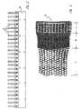
- FIG. 3shows the block 2 at the transition from the unexpanded State (Hobe material) in area a over a partially expanded state in area b into one essentially fully expanded state in area c.
- the warming by the Infrared emitter 5takes place at least partially in area b, so that the heat radiation also in the inside of block 2 can enter.
Landscapes
- Engineering & Computer Science (AREA)
- Mechanical Engineering (AREA)
- Lining Or Joining Of Plastics Or The Like (AREA)
- Treatment Of Fiber Materials (AREA)
- Laminated Bodies (AREA)
- Chain Conveyers (AREA)
Abstract
Description
Translated fromGermanDie Erfindung betrifft ein Verfahren zum Zusammenfügen einer Vielzahl von Abschnitten einesthermoplastischen Bahnmaterials, insbesondere eines Vliesmaterials aus thermoplastischenKunstfasern, zu einem expandierbaren Block Die Erfindung betrifft auch eine Vorrichtung zumZusammenfügen einer Vielzahl von Abschnitten eines thermoplastischen Bahnmaterials.The invention relates to a method for joining a plurality of sections of athermoplastic web material, in particular a nonwoven material made of thermoplasticSynthetic fibers, into an expandable block The invention also relates to a device forJoining a plurality of sections of a thermoplastic sheet material.
Die CH 684 589 offenbart Verfahren und Vorrichtung zum Vereinzeln von in einem stationärenBogenmagazin gestapelten Druckbogen. Die Vorrichtung umfaßt zwei distanzierte Scheiben, aufdenen trommelförmige Mitnehmer 7 angebracht sind, die planetär angetrieben werden. Um dieMitnehmer ist ein Führungsband gespannt anliegend, daß mit den Mitnehmern reibungsschlüssigverbunden ist und dadurch den Transport des von einem Stapel abgezogenen Druckbogenszwischen Mitnehmer und Führungsband gewährleistet. Im Betrieb wird der Druckbogen durchden trommelförmigen Mitnehmer unter Wirkung von Saugnäpfen durch abschälen entnommenund vereinzelt.CH 684 589 discloses methods and apparatus for separating in a stationarySheet magazine stacked printed sheets. The device comprises two spaced diskswhich drum-
Der Erfindung liegt die Aufgabe zugrunde, ein Verfahren zum Zusammenfügen von Abschnittenaus einem thermoplastischen Bahnmaterial, insbesondere einem thermoplastischenKunstfaservlies, zu einem Block zu schaffen, der zu einem leichten Konstruktionswerkstoffweiterverarbeitet werden kann. Durch das Verfahren soll ein Block aus Abschnitten geschaffenwerden, der mit geringem Aufwand ohne Verwendung von Klebstoff und ohne Faltprägungen desBahnmaterials hergestellt und expandiert werden kann. Ferner soll eine Vorrichtung zurHerstellung eines expandierbaren Blocks aus Abschnitten geschaffen werden, die hoheProduktionsgeschwindigkeiten erlaubt. Weitere Vorteile der Erfindung ergeben sich aus derfolgenden Beschreibung.The invention has for its object a method for joining sectionsmade of a thermoplastic sheet material, in particular a thermoplasticSynthetic fiber fleece to create a block that becomes a lightweight construction materialcan be processed further. The process is intended to create a block of sectionsbe made with little effort without the use of glue and without fold embossingWeb material can be manufactured and expanded. Furthermore, a device forMaking an expandable block from sections that are highProduction speeds allowed. Further advantages of the invention result from thefollowing description.
Diese Aufgabe wird bei dem eingangs genannten Verfahren erfindungsgemäß dadurch gelöst, daßman
zu dem letzten Abschnitt des gebildeten Blocks bringt, b) einander gegenüberliegende ersteStreifen auf den Oberflächen des ersten und letzten Abschnitts auf die Schweißtemperatur desMaterials erwärmt,
to the last section of the block formed, b) heating opposing first strips on the surfaces of the first and last sections to the welding temperature of the material,
Durch das Verfahren wird ein expansionsfähiges Hobe-Material ohne Verwendung von Klebstoffund ohne Prägefaltungen des Bahnmaterials geschaffen. Das Verfahren eignet sich zur Erreichunghoher Produktionsgeschwindigkeiten. Dem Verfahren kann die Bildung der einzelnen zusammenzufügendenAbschnitte aus einer Bahn vorgeschaltet werden. Man kann jedoch auch von denAbschnitten direkt ausgehen, wenn diese als solche angeliefert werden. Verfahrensprodukt ist dasHobe-Material, das wegen seines geringen Raumbedarfs an einen Weiter-oder Endverarbeitergeliefert wird. Selbstverständlich ist es auch möglich, das Hobe-Material im Anschluß an dieerfindungsgemäße Herstellung direkt zu expandieren. Durch das erfindungsgemäße Verfahrenwird der Hobe-Material-Block durch taktweise Addition von Abschnitten gebildet, wobei sein Querschnitt durch die Abschnittsgrößebestimmt ist. Die Breite des Materials (entsprechend der Breite des ursprünglichen Bahnmaterials)kann bis zu 5,20 m oder mehr betragen. Die Höhe des erzeugten Blocks entspricht der freiwählbaren Breite der Bahnabschnitte.The process makes an expandable hobe material without the use of glueand created without embossing the web material. The procedure is suitable for achieving thishigh production speeds. The process can be the formation of the individual to be put togetherSections from a track are connected upstream. But you can also from theSections run out directly if they are delivered as such. Process product is thatHobe material, which due to its small space requirement for a further or final processoris delivered. Of course, it is also possible to use the Hobe material after theexpand directly according to the inventive production. By the method according to the inventionis the hobe material block throughintermittent addition of sections formed, its cross section through the section sizeis determined. The width of the material (corresponding to the width of the original web material)can be up to 5.20 m or more. The height of the generated block corresponds to the freeselectable width of the track sections.
Nach der bevorzugten Ausführungsform des erfindungsgemäßen Verfahrens werden in den Stufenc) und f) der zu addierende Abschnitt und der aus den Abschnitten gebildete Block zu ihrerZusammenführung entgegengerichtet aufeinander zu bewegt. Dadurch steht für die anschließendeKontaktierung und Verschweissung eine längere Andruckzeit zur Verfügung, was für dieVerschweissung vorteilhaft ist.According to the preferred embodiment of the method according to the invention, the stepsc) and f) the section to be added and the block formed from the sections to itMerge moving in opposite directions. This stands for the subsequent oneContacting and welding a longer press time is available, which for theWelding is advantageous.
Nach der bevorzugten Ausführungsform des erfindungsgemäßen Verfahrens bewegt man in denStufen c) und f) den addierten Abschnitt und den aus den Abschnitten gebildeten Block währendund/oder nach ihrer Kontaktierung um die Dicke eines Abschnitts gleichgerichtet inProduktionsrichtung. Gleichzeitig mit der Addition eines Abschnitts wird somit der Block um dieDicke eines Abschnitts in Produktionsrichtung weiterbewegt.According to the preferred embodiment of the method according to the invention, one moves into theStages c) and f) during the added section and the block formed from the sectionsand / or after contacting them in the same direction as the thickness of a sectionProduction direction. Simultaneously with the addition of a section, the block is added to theThickness of a section moved in the direction of production.
Vorzugsweise hält man den gebildeten Abschnittsblock unter einem zur Produktionsrichtungsenkrechten Klemmdruck. Dieser Klemmdruck erstreckt sich über den vorderen Bereich desBlocks, in dem die Blockbildung erfolgt. Der Klemmdruck ist einstellbar und ermöglicht so dieEinstellung des beim Andrücken und Verschweissen des neuen Abschnitts an dem Blockerreichbaren Schweißdruck.The section block formed is preferably held below one in the direction of productionvertical clamping pressure. This clamping pressure extends over the front area of theBlocks in which the block is formed. The clamping pressure is adjustable and thus enablesSetting of when pressing and welding the new section on the blockachievable welding pressure.
Zweckmäßigerweise erwärmt man zur Bildung eines expandierten Wabenmaterials den durch dieStufen a) bis g) gebildeten Block bis zu seiner Formbarkeit und expandiert ihn dann senkrecht zuseinen Abschnitten, d.h. in Produktionsrichtung.Appropriately heated to form an expanded honeycomb material by theStages a) to g) formed block to its formability and then expanded perpendicular to itits sections, i.e. in the production direction.
Überraschenderweise hat sich gezeigt, daß der Hobe-Material-Block schon kurz nach seinerBildung unter Erwärmung expandiert werden kann, ohne daß dadurch die Schweißflächen reissenoder anderweitig beeinträchtigt werden. Dabei erfolgt die Erwärmung zur Formbarkeit zwecksExpansion auf eine Temperatur, die erheblich unterhalb der Schweißtemperatur liegt. Bei einemVliesmaterial aus Polypropylenfasern beispielsweise genügt eine Erwärmung auf 75 bis 85°C,während die Schweißtemperatur oberhalb von 120°C, z.B. bei 165°C liegt.Surprisingly, it has been shown that the hobe material block shortly after itFormation under heating can be expanded without tearing the welding surfacesor otherwise impaired. The heating takes place for the purpose of formabilityExpansion to a temperature that is significantly below the welding temperature. At aNon-woven material made of polypropylene fibers, for example, is sufficient to heat to 75 to 85 ° C,while the welding temperature is above 120 ° C, e.g. is at 165 ° C.
Vorzugsweise erwärmt man den gebildeten Block durch Infrarotstrahlung. Dabei erfolgt dieErwärmung vorteilhaft in einem Bereich des Blocks, in dem dieser schon teilweise expandiert ist.Die Wärmestrahlung (oder ein anderer Wärmeträger) ist in die durch die Teilexpansiongebildeten Zwischenräume gerichtet, so daß eine ziemlich gleichmäßige Erwärmung im gesamtenBlockquerschnitt erreicht wird.The block formed is preferably heated by infrared radiation. TheHeating advantageously in an area of the block in which it has already partially expanded.The heat radiation (or another heat transfer medium) is due to the partial expansionformed gaps directed so that a fairly even heating throughoutBlock cross section is reached.
Vorzugsweise transportiert man die Abschnitte auf einer kreisbogenförmigen Bahn taktweise indie Schweißposition vor dem aus den Abschnitten gebildeten Block. Auf diese Weise könnenmehrere Abschnitte auf einem Rotor hintereinander transportiert und hoheProduktionsgeschwindigkeiten erreicht werden.The sections are preferably transported in cycles on an arc-shaped paththe welding position in front of the block formed from the sections. That way you canseveral sections transported on a rotor in succession and highProduction speeds can be achieved.
Die Aufgabe wird ferner durch eine Vorrichtung zum Zusammenfügen einer Vielzahl vonAbschnitten eines thermoplastischen Bahnmaterials zu einem expandierfähigen Block gelöst, dieerfindungsgemäß gekennzeichnet ist durch
ein Durchlaufmagazin zur Aufnahme des aus den Abschnitten gebildeten Blocks undeinen vor dem Durchlaufmagazin angeordneten Rotor mit mehreren, über den Rotorumfangverteilten Stationen aus
a continuous magazine for receiving the block formed from the sections and a rotor arranged in front of the continuous magazine with a plurality of stations distributed over the circumference of the rotor
Der Rotor ist zwischen dem Durchlaufmagazin und einer Übernahmestation angeordnet. Erübernimmt an der stationären Übernahmestation jeweils einzelne fertig zugeschnittene Abschnitteund transportiert diese vor das Durchlaufmagazin, das den bereits gebildeten Block enthält. Indieser Position vor dem Durchlaufmagazin erfolgt die Verschweißung des herantransportiertenAbschnitts mit dem zuvor aus den Abschnitten gebildeten Block. Die auf dem Rotor angeordnetenStationen haben eine mehrfache Funktion. Sie übernehmen und transportieren jeweils einzelneAbschnitte in die Schweißposition vor dem Durchlaufmagazin. Sie erhitzen die einandergegenüberliegenden Flächen des letzten verblockten Abschnitts und des herantransportierten, vor dem verblockten Abschnitt positionierten Abschnitts, und sie bewirken das Andrücken des vordem Block positionierten Abschnitts an den Block.The rotor is arranged between the continuous magazine and a transfer station. Hetakes over individually cut sections at the stationary transfer stationand transports it in front of the continuous magazine that contains the block that has already been formed. InThis position in front of the continuous magazine is used to weld the transported materialSection with the block previously formed from the sections. The arranged on the rotorStations have multiple functions. They take over and transport each oneSections in the welding position in front of the continuous magazine. They heat each other upopposite surfaces of the last blocked section and the transported in frontthe portion positioned in the blocked portion, and they cause the pressing of the frontsection positioned on the block.
Nach der bevorzugten Ausführungsform der erfindungsgemäßen Vorrichtung ist der Rotor miteiner geraden Anzahl von Stationen bestückt und sind die Streifenheizeinrichtungen von einerStation zur nächsten Station axial hin und her versetzt. Hierdurch können die im Blockaufeinanderfolgenden Abschnitte mit entsprechend versetzten Schweißstreifen versehen werden.Der Hobe-Block kann dann durch Expansion zu einem Wabenmaterial mit gleichseitigsechseckigemWabenquerschnitt expandiert werden. Die gerade Anzahl der Stationen auf demRotor kann je nach Größe des Rotors frei gewählt werden; sechs oder acht Stationen sind z.B.eine zweckmäßige Anzahl. Der Versatz der Streifenheizeinrichtungen benachbarter Stationen istbei der Herstellung von Wabenmaterial gleich der doppelten Breite des Schweißstreifens. DieAndruckeinrichtungen können sich über die gesamte Breite des Abschnittsträgers erstrecken. Siekönnen aber auch nur auf der Breite der Schweißstreifen andrücken. In diesem Falle sind dieAndruckeinrichtungen ebenso wie die Streifenheizeinrichtungen von Station zu Station hin und herversetzt.According to the preferred embodiment of the device according to the invention, the rotor is includedan even number of stations and are the strip heaters of oneAxially offset the station to the next station. This allows the in the blocksuccessive sections are provided with appropriately offset welding strips.The Hobe block can then be expanded to an equilateral hexagonal honeycomb materialHoneycomb cross section can be expanded. The even number of stations on theThe rotor can be freely selected depending on the size of the rotor; six or eight stations are e.g.an appropriate number. The offset of the strip heaters from adjacent stations isin the production of honeycomb material equal to twice the width of the welding strip. ThePressure devices can extend over the entire width of the section carrier. shebut can only press on the width of the sweat strips. In this case they arePressure devices as well as the strip heating devices from station to station back and forthadded.
Nach der bevorzugten Ausführungsform sind in den pneumatisch arbeitenden AbschnittsträgernBohrungen ausgebildet, die an eine Unterdruckquelle anschließbar sind. An der Übernahmestationwird ein Abschnitt von dem Abschnittsträger angesaugt und so übernommen. In derSchweißposition vor dem Durchlaufmagazin wird nach erfolgter Erhitzung der Abschnitte durchdie Streifenheizeinrichtung der Unterdruck abgeschaltet, so daß der Abschnitt von demAbschnittsträger freigegeben und unmittelbar danach durch die Andruckeinrichtung an den Blockangedrückt und damit verblockt werden kann.According to the preferred embodiment, the pneumatically working section carriersBores formed which can be connected to a vacuum source. At the transfer stationa section is sucked in by the section carrier and thus taken over. In theThe welding position in front of the continuous magazine is completed after the sections have been heatedthe strip heater turned off the vacuum so that the section of theSection carrier released and immediately afterwards by the pressure device on the blockcan be pressed on and thus blocked.
Zweckmäßigerweise bestehen die Streifenheizeinrichtungen aus einer Vielzahl kammartigausgebildeter Heizelemente, die von Station zu Station um die zweifache Breite desSchweißstreifens gegeneinander versetzt sind. Die Streifenheizeinrichtungen auf dem Rotorkönnen gegen andere Heizeinrichtungen mit anderer Breite und dementsprechend anderemAbstand der kammartigen Heizelemente austauschbar sein. Auf diese Weise kann dieWabengröße verändert werden.The strip heating devices expediently consist of a large number of combstrained heating elements, which is twice the width of the station from station to stationSweatstrip are offset against each other. The strip heaters on the rotorcan against other heating devices with a different width and accordingly differentDistance of the comb-like heating elements to be interchangeable. In this way, theHoneycomb size can be changed.
Vorzugsweise sind die Andruckeinrichtungen als Walzen ausgebildet. Die Walzen können miteinstellbarer Federlagerung versehen sein, so daß der Andruck längs der Schweißstreifenentsprechend der Klemmung des Blocks in dem Durchlaufmagazin verändert werden kann.The pressure devices are preferably designed as rollers. The rollers can withadjustable spring bearing, so that the pressure along the welding stripscan be changed in accordance with the clamping of the block in the continuous magazine.
Wenn aus dem Hobe-Material ein expandiertes Wabenmaterial erzeugt werden soll, sind demDurchlaufmagazin eine Erwärmungseinrichtung und wenigstens ein Expansionswalzenpaarnachgeschaltet. Die Erwärmungseinrichtung kann ein einseitig oder zweiseitig einwirkenderInfrarotstrahler sein. Zweckmäßigerweise erfolgt die Wärmestrahlung in Richtung derSchweißstreifen bzw. nach Teilexpansion in Richtung der gebildeten Kanäle. Die Expansionswalzensind zweckmäßig Bürstenwalzen oder mit einem anderen nachgiebigen Material bekleidetenWalzen, die den expandierten Block ohne Beschädigung erfassen können.If an expanded honeycomb material is to be produced from the Hobe material, that isContinuous magazine a heating device and at least one pair of expansion rollersdownstream. The heating device can be one-way or two-wayBe an infrared heater. The heat radiation expediently takes place in the direction ofSweat strips or after partial expansion in the direction of the channels formed. The expansion rollersare useful brush rollers or clad with another compliant materialRollers that can grasp the expanded block without damage.
Eine Ausführungsform der erfindungsgemäßen Vorrichtung wird nun an Hand der Zeichnungnäher beschrieben. Es zeigen
Figur 1- die Gesamtansicht der Vorrichtung in schematischer Darstellung;
Figur 2- die Frontansicht der kammartigen Streifenheizeinrichtung in vergrößertem Maßstab; und
- Figur 3
- ein Photo des erzeugten Blocks in der Expansionsphase.
- Figure 1
- the overall view of the device in a schematic representation;
- Figure 2
- the front view of the comb-like strip heater on an enlarged scale; and
- Figure 3
- a photo of the generated block in the expansion phase.
Figur 1 zeigt einen Tisch 1 für die Führung eines erfindungsgemäß hergestellten Hobe-Material-Blocks2. Am vorderen Ende des Tisches 1 befindet sich ein Durchlaufmagazin 3 mit einerKlemmeinrichtung (nicht dargestellt), durch die der Block 2 unter einen einstellbaren, senkrechtzur Produktionsrichtung wirkenden Klemmdruck gesetzt werden kann. Der Tisch 1 mit demDurchlaufmagazin 3 ist durch eine Mechanik (nicht dargestellt) in Richtung der Pfeile 4antriebsmäßig hin und her verschiebbar. In Produktionsrichtung hinter dem Durchlaufmagazin 3 istein auf die Oberseite des Hobe-Blocks 2 gerichteter Infrarotstrahler 5 angeordnet, durch den derBlock 2 auf die Verformungstemperatur erwärmt werden kann. In der Produktionsrichtung hinterdem Tisch 1 ist ein Expansionswalzenpaar 15 angeordnet, das mit dem Block in Eingriff ist unddiesen von dem Durchlaufmagazin 3 unter Expansion abzieht. Bei der dargestelltenAusführungsform sind die Expansionswalzen 15 als Borstenwalzen ausgebildet. Der Abstand deroberen Walze von der unteren Walze 15 ist entsprechend der Höhe des Blocks 2 und dergewünschten Andruckkraft einstellbar. In Produktionsrichtung hinter dem Expansionswalzenpaar15 ist ein Förderband 16 angeordnet, das den expandierten Block übernimmt und abtransportiert.FIG. 1 shows a table 1 for guiding a block of material made according to the
Zwischen dem Durchlaufmagazin 3 und einem Abschnittmagazin 7 ist ein über die gesamteAbschnittsbreite reichender Rotor 6 drehbar gelagert. Der Rotor ist mit einem taktweisearbeitenden Antrieb (nicht dargestellt) verbunden. Er trägt auf seinem Umfang gleichmäßig verteilt sechs Stationen, durch die jeweils ein Bahnabschnitt transportiert, mit Schweißstreifen versehenund vor dem Durchlaufmagazin 3 an den Block 2 angedrückt wird. Jede Station umfaßt imwesentlichen drei Aggregate, nämlich einen radial verschiebbaren, balkenförmigenAbschnittsträger 8, eine vor dem Abschnittsträger 8 tangential verschiebbareStreifenheizeinrichtung 9 und eine walzenartige Andruckeinrichtung 10. Die drei Aggregateerstrecken sich im wesentlichen über die gesamte Breite (senkrecht zur Zeichenebene) desRotors 6. Die Verschiebungen der Abschnittsträger 8 und der kammförmigenStreifenheizeinrichtungen 9 erfolgen durch pneumatische Antriebe (nicht dargestellt) und werdenzentral gesteuert. Die Andruckeinrichtung 10 besteht im allgemeinen aus einer federbelastetenWalze, die im Zuge der Rotordrehung den mit Schweißstreifen versehenen Abschnitt von obennach unten an den Hobe-Block 2 andrückt und damit die Verschweissung mit dem Blockvervollständigt.Between the continuous magazine 3 and a
Die Arbeitsweise dieser Vorrichtung ist wie folgt: Vor dem Abschnittsmagazin 7 wird beizurückgezogener Streifenheizeinrichtung 9 der Abschnittsträger 8 aktiviert, wodurch einAbschnitt aus dem Abschnittsmagazin 7 von dem Träger 8 übernommen wird. Während derDrehung des Rotors 6 in Richtung des Pfeils 11 wird bereits die Streifenheizeinrichtung 9ausgefahren, so daß der übernommene Abschnitt zwischen dem Abschnittsträger 8 und denkammartigen Elementen der Heizeinrichtung 12 liegt. Dabei ist der Abschnittsträger 8 in einer vonder Streifenheizeinrichtung 9 zurückgefahrenen Position. Sobald sich diese Station nach dreiTakten vor dem Durchlaufmagazin 3 befindet, werden der Abschnittsträger 8 mit dem Abschnitteinerseits und der Tisch I mit dem Durchlaufmagazin 3 und dem Block 2 andererseits soweitaufeinander zu bewegt, daß sie von der kammförmigen Streifenheizeinrichtung 9 kontaktiertwerden können. Nun wird die kammförmige Streifenheizeinrichtung 9 zwischen dem Abschnitt andem Abschnittsträger 8 und dem Block 2 zurückgezogen, wobei durch Kontaktierung dieSchweißstreifen auf den einander gegenüberliegenden Flächen des Abschnitts und des Blocks 2erzeugt werden. Schließlich werden der Abschnittsträger 8 mit dem Abschnitt und dasDurchlaufmagazin 3 mit dem Block 2 weiter aufeinander zu bewegt, bis die Schweißstreifenaufeinandertreffen. Anschließend fahren der Abschnittsträger 8 und das Durchlaufmagazin 3wieder auseinander, und der Rotor 6 wird weitergetaktet. Dabei fährt dann die Walze derAndruckeinrichtung 10 dieser Station über den verschweißten Abschnitt, wodurch ein erneuterAndruck und ein Vorschub des Blocks 2 um die Dicke des Abschnitts erzeugt werden. DieseVorgänge wiederholen sich, sobald die nächste Station des Rotors vor dem Block 2 steht.The operation of this device is as follows: In front of the
Figur 2 zeigt die Stirnansicht der Streifenheizeinrichtung 9 deren kammartige Heizelemente 12elektrisch auf die zur Verschweißung der Abschnitte erforderliche Temperatur erhitzt werden.FIG. 2 shows the end view of the strip heating device 9 whose comb-
Das in Figur 3 abgebildete Photo zeigt den Block 2 beim Übergang von dem nicht-expandiertenZustand (Hobe-Material) im Bereich a über einen teilexpandierten Zustand im Bereich b in einenim wesentlichen vollständig expandierten Zustand im Bereich c. Die Erwärmung durch denInfrarotstrahler 5 erfolgt wenigstens teilweise im Bereich b, so daß die Wärmestrahlung auch indas Innere des Blocks 2 gelangen kann.The photo shown in Figure 3 shows the
- 1.1.
- Tischtable
- 2.Second
- Blockblock
- 3.Third
- DurchlaufmagazinBy running magazine
- 4.4th
- Pfeilearrows
- 5.5th
- Infrarotstrahlerinfrared Heaters
- 6.6th
- Rotorrotor
- 7.7th
- Abschnittsmagazinsection Magazine
- 8.8th.
- Abschnittsträgersection carrier
- 9.9th
- Einrichtung (Schweißeinrichtung)Device (welding device)
- 10.10th
- Andruckeinrichtungpressure device
- 11.11th
- Pfeilarrow
- 12.12th
- Heizelementeheating elements
- 13.13th
- entfälltdeleted
- 14.14th
- entfälltdeleted
- 15.15th
- Walzeroller
- 16.16th
- Förderbandconveyor belt
Claims (11)
- A device for joining a plurality of portions of acontinuous material for forming a block (2),comprising
a rotor (6) with several stations distributed aboutits circumference for arranging a portion to be addedto the block (2) in an adjoining surface-to-surfacerelationship with a portion which was previously addedto the block (2); and
an apparatus (9) for simultaneously forming manydiscrete, longish and spaced-apart connections betweenthe portion which is being added to the block (2) andthe portion which was previously added to the block(2), whereby the apparatus (9) is comprised of therotor (6) with several stations distributed about itscircumference, for gripping and rotating, along thelongitudinal stretch, at least one of the portionswhich is being added to the block (2) as well theportion which was previously welded to the block (2),in order to provide a plurality of rotating contactareas, where the connections are formed at leastpartially, and where the portion which is being addedto the block (2) as well as the block which waspreviously added to the block (2), find themselves inan adjoining surface-to-surface relationship,
characterised in that
the portions consist of a thermoplastic material andthe apparatus (9) is a welding apparatus (9) so thatthe portion which is being added to the block (2) andthe portion which was previously added to the block(2) are welded together and thereby find themselves inan adjoining surface-to-surface relationship so thateach of the welds has an longish stretch and the weldsare each laterally spaced apart from one another, andthat it is furthermore true to say that the finishedblock (2) can be expanded. - The device according to claim 1characterised in thatthe transport mechanism of the rotor (6) and thewelding apparatus (9) are arranged such that thelongish stretch is essentially upright.
- The device according to claim 1characterised in thatthe rotor (6) arranges the portion to be added to theblock (2) in a discrete adjoining surface-to-surfacerelationship next to the portion which was previouslywelded to the block (2),
whereby the welding apparatus (9) furthermore includesa plurality of heating elements (12) which areattached such that they are positioned in the spacebetween the portion which is to be added to the block(2) and the portion which was previously welded to theblock (2), whereas the portion which is to be added tothe block (2) and the portion which was previouslywelded to the block (2) find themselves in a discrete,spaced apart, adjoining surface-to-surfacerelationship,
whereby furthermore the device is constructed in sucha way that the heating elements (12) are meshing withat least one of the respective portion which is to beadded to the block (2) and the portion which waspreviously welded to the block (2), in order to heatstrips of the portion which is meshing with theheating elements (12) to at least the weldingtemperature of the portion, whereas the heatingelements (12) are arranged in the space between theportion which is to be added to the block (2) and theportion which was previously welded to the block (2);and
the welding apparatus (9) is able to form weldsbetween the portion which is to be added to the block(2) and the portion which was previously welded to the block (2) at the respective positions of the heatedstrips. - The device according to claim 3characterised in thatthe heating elements (12) are designed to perform ato-and-fro movement relative to the transportmechanism of the rotor (6).
- The device according to claim 3characterised in thatthe device is designed such that the heating elements(12) are simultaneously meshing with both the portionwhich is being added to the block (2) and the portionwhich was previously welded to the block (2), in orderto heat strips of both the portion which is to beadded the block (2) and of the portion which waspreviously welded to the block (2) to at least thewelding temperature,
whereby the heating elements (12) are arranged in thespace between the portions. - The device according to claim 5characterised in thatthe heating elements (12) are designed to perform ato-and-fro movement relative to the transportmechanism of the rotor (6).
- A method for joining a plurality of portions of athermoplastic material in order to form a block (2),comprising:a) positioning a portion which is to be added to theblock (2) in an adjoining surface-to-surfacerelationship with a portion which was previouslyadded to the block (2);b) heating first strips to at least the weldingtemperature of the portions, whereby the firststrips find themselves on the opposing surfaces ofthe portion which is being added to the block (2) and the portion which was previously added to theblock (2);c) pressing together the surfaces of the portionwhich is being added to the block (2) and of theportion which was previously added to the block(2), so that the first strips of the portion whichwas previously added to the block (2) and thefirst strips of the portion which was added to theblock (2) meet up with each other respectively,and whereby the portion which is being added tothe block (2) and the portion which was previouslyadded to the block (2) are thermally fusedtogether, and the portion which is being added tothe block (2) is the last portion previously addedto the block (2);d) positioning a portion which is to be added to theblock (2) in an adjoining surface-to-surfacerelationship with a portion which was previouslyadded to the block (2);e) heating second strips to at least the weldingtemperature of the portions whereby the secondstrips find themselves on opposing surfaces of theportion which is being added to the block (2) andthe portion which was previously added to theblock (2);f) pressing together the surfaces of the portionwhich is being added to the block (2) and theportion which was previously added to the block(2), so that the second strips of the portionwhich is been added to the block (2) and thesecond strips of the portion which was previouslywelded to the block meet up with each otherrespectively, and whereby the portion which isbeing added to the block (2) and the portion whichwas previously added to the block are thermallyfused together and the portion which is being added to the block (2) is the last portionpreviously added to the block (2);g) continuously repeating the steps a) to f) withmany further portions.
- The method according to claim 7characterised in thatit comprises heating the block (2) to at least thepoint of the plastic deformation and expansion of theblock (2) in order to transform the block (2) into ahoneycomb material.
- The method according to claim 7characterised in thatthe portions comprise thermoplastic fleece fabrics.
- The method according to claim 7characterised in thatthe pressing together of the surfaces of the portionwhich is being added to the block (2) and the portionwhich was previously added to the block (2) includes arotor (6) impacting against and, at the same point intime, rotating past at least one of the portions whichare to be added to the block or the portion which waspreviously added to the block (2).
- The method according to claim 10characterised in thatthe portions comprise thermoplastic fleece fibres.
Applications Claiming Priority (1)
| Application Number | Priority Date | Filing Date | Title |
|---|---|---|---|
| PCT/DE2000/000070WO2001051273A1 (en) | 2000-01-11 | 2000-01-11 | Method and device for joining sections of a thermoplastic continuous web material |
Publications (2)
| Publication Number | Publication Date |
|---|---|
| EP1254019A1 EP1254019A1 (en) | 2002-11-06 |
| EP1254019B1true EP1254019B1 (en) | 2004-10-13 |
Family
ID=5647399
Family Applications (1)
| Application Number | Title | Priority Date | Filing Date |
|---|---|---|---|
| EP00902554AExpired - LifetimeEP1254019B1 (en) | 2000-01-11 | 2000-01-11 | Method and device for joining sections of a thermoplastic continuous web material |
Country Status (7)
| Country | Link |
|---|---|
| US (4) | US6837962B2 (en) |
| EP (1) | EP1254019B1 (en) |
| JP (1) | JP3992983B2 (en) |
| AT (1) | ATE279316T1 (en) |
| CA (1) | CA2396933A1 (en) |
| DE (1) | DE50008275D1 (en) |
| WO (1) | WO2001051273A1 (en) |
Families Citing this family (8)
| Publication number | Priority date | Publication date | Assignee | Title |
|---|---|---|---|---|
| EP1254019B1 (en)* | 2000-01-11 | 2004-10-13 | Versacore Industrial Corporation | Method and device for joining sections of a thermoplastic continuous web material |
| DE10248177B4 (en)* | 2002-10-16 | 2004-08-12 | Wt Wickeltechnik Gmbh | Plant for the production of block and plate elements with a hexagonal honeycomb structure made of thermoplastic material |
| US7535991B2 (en)* | 2006-10-16 | 2009-05-19 | Oraya Therapeutics, Inc. | Portable orthovoltage radiotherapy |
| DE102008005220B4 (en)* | 2008-01-18 | 2016-07-14 | Bernard J. Michels | Honeycomb material sheet welding machine |
| USD609922S1 (en)* | 2008-04-23 | 2010-02-16 | Polymer Group, Inc. | Nonwoven fabric |
| EP2311629B1 (en) | 2009-10-16 | 2011-05-25 | Rieter Technologies AG | Honeycomb sandwich construction for the automotive industry |
| CN109435265A (en)* | 2018-12-18 | 2019-03-08 | 振石集团华美新材料有限公司 | Continuous glass-fiber enhances cellular thermoplastic cored structure and its manufacturing equipment and manufacturing method |
| CN111633994B (en)* | 2020-06-30 | 2025-03-25 | 东莞市精溢高周波机械有限公司 | A plastic honeycomb core weaving forming mold |
Family Cites Families (46)
| Publication number | Priority date | Publication date | Assignee | Title |
|---|---|---|---|---|
| USRE26287E (en) | 1967-10-17 | Core manufacture | ||
| US2975263A (en) | 1954-07-06 | 1961-03-14 | John J Foster Mfg Co | Method for producing honeycomb structures |
| US2821616A (en) | 1955-08-15 | 1958-01-28 | Louis H Spott | Method and apparatus for making honeycomb material |
| US3283118A (en) | 1956-12-10 | 1966-11-01 | Hexcel Products Inc | Resistance welded honeycomb core and method of and machine for making same |
| US2951145A (en)* | 1958-04-28 | 1960-08-30 | John J Foster Mfg Co | Method and apparatus for fabricating honeycomb core |
| US2968712A (en) | 1959-08-07 | 1961-01-17 | Hexcel Products Inc | Pneumatic hold down device |
| US3007834A (en) | 1960-06-17 | 1961-11-07 | Dow Chemical Co | Honeycomb fabrication |
| GB1016692A (en) | 1961-04-11 | 1966-01-12 | Broadbent & Sons Ltd Thomas | Improved length measuring device for automatic folders |
| US3077533A (en) | 1961-04-17 | 1963-02-12 | Rohr Aircraft Corp | Novel framework for honeycomb core machine |
| DE1479016A1 (en)* | 1962-10-04 | 1969-04-24 | Kalk Chemische Fabrik Gmbh | Process for the production of decorative, structural or reinforcement elements from thermoplastics |
| US3134705A (en)* | 1962-10-15 | 1964-05-26 | Dow Chemical Co | Honeycomb fabrication |
| US3379594A (en) | 1963-10-24 | 1968-04-23 | Dow Chemical Co | Honeycomb fabrication |
| US3356555A (en) | 1964-10-29 | 1967-12-05 | Hexcel Corp | Method and apparatus for the manufacture of honeycomb product |
| US3675522A (en)* | 1970-05-13 | 1972-07-11 | Hexcel Corp | Method and apparatus for stacking sheets |
| US4174987A (en) | 1978-04-07 | 1979-11-20 | The Boeing Company | Method of making heat exchange structure |
| FR2595874B1 (en) | 1986-03-13 | 1989-11-17 | Boeing Co | DUAL MODE SIGNAL SEPARATOR |
| JPH01192536A (en) | 1988-01-27 | 1989-08-02 | Ube Ind Ltd | Polyimide honeycomb core and its manufacturing method |
| US4957577A (en) | 1988-04-04 | 1990-09-18 | Plascore, Inc. | Method for making welded honeycomb core |
| DE3820718C1 (en)* | 1988-06-18 | 1989-05-11 | Hans Aesch Ch Schmidlin | |
| US5102485A (en)* | 1989-02-01 | 1992-04-07 | International Paper Company | Apparatus for continuous feeding and synchronized application of fitments to carton blanks and related method |
| JPH0829571B2 (en)* | 1989-08-07 | 1996-03-27 | 王子建材工業株式会社 | Method for manufacturing laminated body for honeycomb structure |
| US5039567A (en) | 1989-12-04 | 1991-08-13 | Supracor Systems, Inc. | Resilient panel having anisotropic flexing characteristics and method of making same |
| US5549773A (en) | 1990-02-05 | 1996-08-27 | Northrop Grumman Corporation | Woven preform/magnetic press process for thermoplastic honeycomb cores |
| US5131970A (en) | 1990-03-02 | 1992-07-21 | Northrop Corporation | Block-bonded process for producing thermoplastic resin impregnated fiber honeycomb core |
| US5399221A (en) | 1990-05-04 | 1995-03-21 | Northrop Grumman Corporation | Continuous process for forming fiber-reinforced high temperature thermoplastic resin honeycomb structures |
| US5217556A (en) | 1990-05-31 | 1993-06-08 | Hexcel Corporation | Continuous process for the preparation of unitary thermoplastic honeycomb containing areas with different physical properties |
| US5139596A (en) | 1990-05-31 | 1992-08-18 | Basf Structural Materials, Inc. | Continuous process for the preparation of thermoplastic honeycomb |
| US5252163A (en) | 1990-05-31 | 1993-10-12 | Hexcel Corporation | Process for the preparation of thermoplastic honeycomb shaped structures without machining |
| MX9204071A (en) | 1991-07-12 | 1993-04-01 | Hexcel Corp | METHOD AND APPARATUS FOR MAKING THERMOPLASTIC ALVEOLAR STRUCTURES, THERMALLY CAST. |
| CH683829A5 (en) | 1991-08-05 | 1994-05-31 | Alusuisse Lonza Services Ag | A method of manufacturing a honeycomb core from a ribbon-shaped foil, apparatus for performing the method and use of the honeycomb core for laminated plates. |
| US5296280A (en) | 1991-11-25 | 1994-03-22 | E. I. Du Pont De Nemours And Company | Process for making a honeycomb core from a honeycomb half-cell structure and honeycomb core made thereby |
| CH684589A5 (en)* | 1992-03-09 | 1994-10-31 | Grapha Holding Ag | Process and apparatus for separating printed sheets stacked in a stationary sheet magazine |
| US5354394A (en) | 1992-11-10 | 1994-10-11 | Seeton Technologies | Apparatus and method for forming honeycomb core |
| JPH07214709A (en)* | 1994-02-07 | 1995-08-15 | Showa Aircraft Ind Co Ltd | Honeycomb core and method for manufacturing the same |
| US5746879A (en) | 1994-04-13 | 1998-05-05 | Plascore, Inc. | Apparatus for making honeycomb from substrates and node strips |
| US5635237A (en)* | 1995-01-31 | 1997-06-03 | Rawhide Select | Method of manufacturing substantially pure rawhide pet products |
| US5735986A (en) | 1995-11-03 | 1998-04-07 | Fell; Barry Michael | Continuous process for the preparation of honeycomb structural material and apparatus suitable for use therein |
| US5897730A (en) | 1996-07-16 | 1999-04-27 | Teh Yor Industrial Co., Ltd. | Method for producing shade material |
| US5792295A (en) | 1996-08-12 | 1998-08-11 | Plascore, Inc. | Honeycomb fabrication |
| AU4426197A (en) | 1996-09-20 | 1998-04-14 | Hexcel Corporation | Improved lightweight, self-sustaining anisotropic honeycomb material |
| GB9706261D0 (en)* | 1997-03-26 | 1997-05-14 | Molins Plc | Blank handling apparatus |
| US6146484A (en) | 1998-05-21 | 2000-11-14 | Northrop Grumman Corporation | Continuous honeycomb lay-up process |
| DE19830380A1 (en)* | 1998-07-08 | 2000-01-13 | Gerhard Klaus Hering | Joining sections of thermoplastic fleece to form expansible sectional block |
| DE19916842A1 (en) | 1999-04-14 | 2000-10-19 | Gerhard Klaus Hering | Method for transverse cutting film material, and to stack cut sections; involves cutting film sections between stationary and rotating knives and transporting on curved path to stacking station |
| DE19928712C1 (en) | 1999-06-23 | 2000-11-16 | Achim Kehl | Free-standing flexible honeycomb material is composed of corrugated strips with a U-shaped cross section bonded together at their contact points |
| EP1254019B1 (en)* | 2000-01-11 | 2004-10-13 | Versacore Industrial Corporation | Method and device for joining sections of a thermoplastic continuous web material |
- 2000
- 2000-01-11EPEP00902554Apatent/EP1254019B1/ennot_activeExpired - Lifetime
- 2000-01-11ATAT00902554Tpatent/ATE279316T1/ennot_activeIP Right Cessation
- 2000-01-11CACA002396933Apatent/CA2396933A1/ennot_activeAbandoned
- 2000-01-11DEDE2000508275patent/DE50008275D1/ennot_activeExpired - Fee Related
- 2000-01-11JPJP2001551675Apatent/JP3992983B2/ennot_activeExpired - Fee Related
- 2000-01-11WOPCT/DE2000/000070patent/WO2001051273A1/enactiveIP Right Grant
- 2001
- 2001-08-21USUS09/934,177patent/US6837962B2/ennot_activeExpired - Fee Related
- 2002
- 2002-07-11USUS10/193,661patent/US6907912B2/ennot_activeExpired - Fee Related
- 2005
- 2005-06-20USUS11/157,111patent/US7559351B2/ennot_activeExpired - Fee Related
- 2009
- 2009-06-17USUS12/486,510patent/US8075727B2/ennot_activeExpired - Fee Related
Also Published As
| Publication number | Publication date |
|---|---|
| ATE279316T1 (en) | 2004-10-15 |
| US6837962B2 (en) | 2005-01-04 |
| US20090250167A1 (en) | 2009-10-08 |
| EP1254019A1 (en) | 2002-11-06 |
| JP2003519730A (en) | 2003-06-24 |
| US6907912B2 (en) | 2005-06-21 |
| CA2396933A1 (en) | 2001-07-19 |
| US20060144524A1 (en) | 2006-07-06 |
| US7559351B2 (en) | 2009-07-14 |
| US8075727B2 (en) | 2011-12-13 |
| US20020092603A1 (en) | 2002-07-18 |
| WO2001051273A1 (en) | 2001-07-19 |
| DE50008275D1 (en) | 2004-11-18 |
| JP3992983B2 (en) | 2007-10-17 |
| US20030037861A1 (en) | 2003-02-27 |
Similar Documents
| Publication | Publication Date | Title |
|---|---|---|
| AT401610B (en) | METHOD AND DEVICE FOR PRODUCING WRAPPED, IN ESSENTIAL CYLINDRICAL ITEMS, IN PARTICULAR TAMPONS | |
| EP0344765B1 (en) | Method and arrangement for glueing flat parts | |
| DE60033065T2 (en) | Material parts in favorable cuts | |
| EP0531251B1 (en) | Method and apparatus for making a honey comb case from foil webs, and use of such a case as case for continuously produced composite panels | |
| CH651505A5 (en) | METHOD FOR PRODUCING A BOOK FOR A BOOK, A BOOKLET OR A BROCHURE, AND DEVICE FOR CARRYING OUT THE METHOD. | |
| DE3203992C2 (en) | Arrangement for making sanitary napkins | |
| DE3109981A1 (en) | "VACUUM MOLDING MACHINE" | |
| DE1479848B2 (en) | Method and device for Her provide perforated carrier bags made of weldable material | |
| CH686620A5 (en) | Method and apparatus for producing bookers or brochures. | |
| DE69108237T2 (en) | CONTINUOUS FOLDING DEVICE FOR FILMS FOR THE PRODUCTION OF SUPPLEMENTAL WRINKLES AND ADDITIONAL DEVICE FOR REALIZING WRINKLESS AREAS. | |
| EP1254019B1 (en) | Method and device for joining sections of a thermoplastic continuous web material | |
| DE3018987A1 (en) | METHOD AND DEVICE FOR THE PRODUCTION OF STACKS OF SHEETS | |
| DE3020009A1 (en) | DEVICE FOR PRODUCING BAGS FROM A PLASTIC TUBE TUBE | |
| DE2828901B2 (en) | Device for transversely assembling and gluing flat workpieces made of wood | |
| CH622462A5 (en) | ||
| EP0376007B1 (en) | Machine for producing carrier bags with handle openings and welded-on thermoplastic reinforcement tags surrounding them | |
| EP0041685A1 (en) | Process and apparatus for joining metal or synthetic spiral elements into a belt | |
| CH466957A (en) | Method and device for the manufacture of filter inserts | |
| DE19830380A1 (en) | Joining sections of thermoplastic fleece to form expansible sectional block | |
| DE2248181B2 (en) | METHOD AND DEVICE FOR BONDING AREA-SHAPED TEXTILE PIECES | |
| EP1410897B1 (en) | Device for producing block elements and panels from a thermoplastic material with hexagonal honeycomb structure | |
| DE2351069C3 (en) | Machine for dividing foils, plates, trays or other objects in the transverse and longitudinal direction | |
| DE1918297C3 (en) | Device for wrapping a cuboid object stacked optionally from individual parts | |
| EP0210504A2 (en) | Method and apparatus of making a hollow plastic panel | |
| DE2167117C2 (en) | Continuous web of successively linked business forms |
Legal Events
| Date | Code | Title | Description |
|---|---|---|---|
| PUAI | Public reference made under article 153(3) epc to a published international application that has entered the european phase | Free format text:ORIGINAL CODE: 0009012 | |
| 17P | Request for examination filed | Effective date:20020525 | |
| AK | Designated contracting states | Kind code of ref document:A1 Designated state(s):AT BE CH CY DE DK ES FI FR GB GR IE IT LI LU MC NL PT SE | |
| 17Q | First examination report despatched | Effective date:20030120 | |
| GRAP | Despatch of communication of intention to grant a patent | Free format text:ORIGINAL CODE: EPIDOSNIGR1 | |
| GRAS | Grant fee paid | Free format text:ORIGINAL CODE: EPIDOSNIGR3 | |
| GRAA | (expected) grant | Free format text:ORIGINAL CODE: 0009210 | |
| AK | Designated contracting states | Kind code of ref document:B1 Designated state(s):AT BE CH CY DE DK ES FI FR GB GR IE IT LI LU MC NL PT SE | |
| PG25 | Lapsed in a contracting state [announced via postgrant information from national office to epo] | Ref country code:IT Free format text:LAPSE BECAUSE OF FAILURE TO SUBMIT A TRANSLATION OF THE DESCRIPTION OR TO PAY THE FEE WITHIN THE PRESCRIBED TIME-LIMIT;WARNING: LAPSES OF ITALIAN PATENTS WITH EFFECTIVE DATE BEFORE 2007 MAY HAVE OCCURRED AT ANY TIME BEFORE 2007. THE CORRECT EFFECTIVE DATE MAY BE DIFFERENT FROM THE ONE RECORDED. Effective date:20041013 Ref country code:FI Free format text:LAPSE BECAUSE OF FAILURE TO SUBMIT A TRANSLATION OF THE DESCRIPTION OR TO PAY THE FEE WITHIN THE PRESCRIBED TIME-LIMIT Effective date:20041013 Ref country code:GB Free format text:LAPSE BECAUSE OF FAILURE TO SUBMIT A TRANSLATION OF THE DESCRIPTION OR TO PAY THE FEE WITHIN THE PRESCRIBED TIME-LIMIT Effective date:20041013 Ref country code:FR Free format text:LAPSE BECAUSE OF FAILURE TO SUBMIT A TRANSLATION OF THE DESCRIPTION OR TO PAY THE FEE WITHIN THE PRESCRIBED TIME-LIMIT Effective date:20041013 Ref country code:IE Free format text:LAPSE BECAUSE OF FAILURE TO SUBMIT A TRANSLATION OF THE DESCRIPTION OR TO PAY THE FEE WITHIN THE PRESCRIBED TIME-LIMIT Effective date:20041013 Ref country code:NL Free format text:LAPSE BECAUSE OF FAILURE TO SUBMIT A TRANSLATION OF THE DESCRIPTION OR TO PAY THE FEE WITHIN THE PRESCRIBED TIME-LIMIT Effective date:20041013 | |
| REG | Reference to a national code | Ref country code:GB Ref legal event code:FG4D Free format text:NOT ENGLISH | |
| REG | Reference to a national code | Ref country code:CH Ref legal event code:EP | |
| REG | Reference to a national code | Ref country code:IE Ref legal event code:FG4D Free format text:GERMAN | |
| REF | Corresponds to: | Ref document number:50008275 Country of ref document:DE Date of ref document:20041118 Kind code of ref document:P | |
| PG25 | Lapsed in a contracting state [announced via postgrant information from national office to epo] | Ref country code:CY Free format text:LAPSE BECAUSE OF FAILURE TO SUBMIT A TRANSLATION OF THE DESCRIPTION OR TO PAY THE FEE WITHIN THE PRESCRIBED TIME-LIMIT Effective date:20050111 Ref country code:LU Free format text:LAPSE BECAUSE OF NON-PAYMENT OF DUE FEES Effective date:20050111 | |
| PG25 | Lapsed in a contracting state [announced via postgrant information from national office to epo] | Ref country code:GR Free format text:LAPSE BECAUSE OF FAILURE TO SUBMIT A TRANSLATION OF THE DESCRIPTION OR TO PAY THE FEE WITHIN THE PRESCRIBED TIME-LIMIT Effective date:20050113 Ref country code:SE Free format text:LAPSE BECAUSE OF FAILURE TO SUBMIT A TRANSLATION OF THE DESCRIPTION OR TO PAY THE FEE WITHIN THE PRESCRIBED TIME-LIMIT Effective date:20050113 Ref country code:DK Free format text:LAPSE BECAUSE OF FAILURE TO SUBMIT A TRANSLATION OF THE DESCRIPTION OR TO PAY THE FEE WITHIN THE PRESCRIBED TIME-LIMIT Effective date:20050113 | |
| PG25 | Lapsed in a contracting state [announced via postgrant information from national office to epo] | Ref country code:ES Free format text:LAPSE BECAUSE OF FAILURE TO SUBMIT A TRANSLATION OF THE DESCRIPTION OR TO PAY THE FEE WITHIN THE PRESCRIBED TIME-LIMIT Effective date:20050124 | |
| PG25 | Lapsed in a contracting state [announced via postgrant information from national office to epo] | Ref country code:AT Free format text:LAPSE BECAUSE OF NON-PAYMENT OF DUE FEES Effective date:20050131 Ref country code:LI Free format text:LAPSE BECAUSE OF NON-PAYMENT OF DUE FEES Effective date:20050131 Ref country code:MC Free format text:LAPSE BECAUSE OF NON-PAYMENT OF DUE FEES Effective date:20050131 Ref country code:BE Free format text:LAPSE BECAUSE OF NON-PAYMENT OF DUE FEES Effective date:20050131 Ref country code:CH Free format text:LAPSE BECAUSE OF NON-PAYMENT OF DUE FEES Effective date:20050131 | |
| NLV1 | Nl: lapsed or annulled due to failure to fulfill the requirements of art. 29p and 29m of the patents act | ||
| GBV | Gb: ep patent (uk) treated as always having been void in accordance with gb section 77(7)/1977 [no translation filed] | Effective date:20041013 | |
| REG | Reference to a national code | Ref country code:IE Ref legal event code:FD4D | |
| BERE | Be: lapsed | Owner name:VERSACORE INDUSTRIAL CORP. Effective date:20050131 | |
| PG25 | Lapsed in a contracting state [announced via postgrant information from national office to epo] | Ref country code:DE Free format text:LAPSE BECAUSE OF NON-PAYMENT OF DUE FEES Effective date:20050802 | |
| PLBE | No opposition filed within time limit | Free format text:ORIGINAL CODE: 0009261 | |
| STAA | Information on the status of an ep patent application or granted ep patent | Free format text:STATUS: NO OPPOSITION FILED WITHIN TIME LIMIT | |
| REG | Reference to a national code | Ref country code:CH Ref legal event code:PL | |
| 26N | No opposition filed | Effective date:20050714 | |
| EN | Fr: translation not filed | ||
| BERE | Be: lapsed | Owner name:*VERSACORE INDUSTRIAL CORP. Effective date:20050131 | |
| PG25 | Lapsed in a contracting state [announced via postgrant information from national office to epo] | Ref country code:PT Free format text:LAPSE BECAUSE OF NON-PAYMENT OF DUE FEES Effective date:20050313 |