EP1251582A1 - Data transmission system - Google Patents
Data transmission systemDownload PDFInfo
- Publication number
- EP1251582A1 EP1251582A1EP01810375AEP01810375AEP1251582A1EP 1251582 A1EP1251582 A1EP 1251582A1EP 01810375 AEP01810375 AEP 01810375AEP 01810375 AEP01810375 AEP 01810375AEP 1251582 A1EP1251582 A1EP 1251582A1
- Authority
- EP
- European Patent Office
- Prior art keywords
- data transmission
- transmission system
- data
- pipeline
- antennas
- Prior art date
- Legal status (The legal status is an assumption and is not a legal conclusion. Google has not performed a legal analysis and makes no representation as to the accuracy of the status listed.)
- Withdrawn
Links
Images
Classifications
- H—ELECTRICITY
- H01—ELECTRIC ELEMENTS
- H01P—WAVEGUIDES; RESONATORS, LINES, OR OTHER DEVICES OF THE WAVEGUIDE TYPE
- H01P3/00—Waveguides; Transmission lines of the waveguide type
- H01P3/12—Hollow waveguides
Definitions
- the present inventionrelates to the field of data transmission, especially in the field of high speed data transmission. It affects a data transmission system according to the preamble of claim 1.
- the density of such a networkis very close to larger conurbations.
- a system for using existing hollow duct systems of a building, in particular ventilation pipes, for the efficient transmission of electromagnetic waves in the interior of a buildingis known.
- the systemalso includes antennas for feeding the electromagnetic waves into the cables. Through openings in the ventilation pipes, the electromagnetic waves enter different rooms separated by walls inside the building. These openings in the ventilation pipes inhibit the propagation of the electromagnetic waves. As a result, larger distances cannot be covered without repeatedly strengthening the waves.
- the object of the present inventionis to provide a data transmission system for transmitting data between at least two data terminals via a data transmission medium according to the preamble of claim 1, in which the data transmission medium can be relocated and maintained without the problems mentioned above.
- the objectis achieved according to independent claim 1.
- the essence of the inventionis that the data transmission medium of the data transmission system with at least two data terminals, each having a modulator for modulating the data on an electromagnetic wave and / or a demodulator for demodulating the data from an electromagnetic wave and an antenna for transmitting and / or Receiving electromagnetic waves comprise, as a waveguide in the form of a closed, at least partially fluid-carrying pipeline.
- the existing pipeswhich are connected to form a dense network and are not primarily intended for data transmission, are used as waveguides. Thanks to the use of existing infrastructure, there is no need to intervene in the landscape and to change buildings when laying and maintaining the data transmission medium. Closed pipelines or piping systems with a metallic encapsulation and / or a highly conductive coating on the inner surface are particularly suitable as data transmission medium. Thanks to the shallow depth of penetration and the high conductivity in the enclosed encapsulation, optimal propagation of the electromagnetic waves is ensured with low losses. In addition, the enclosed encapsulation rsp. the coating shields external fields, which results in a very low noise level.
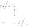
- FIG. 1shows the data transmission system according to the invention with a pipeline.
- a mechanical structuresuch as a pipeline or pipeline for transporting fluids, is used as the data transmission medium in the data transmission system according to the invention.
- 1shows such a pipeline 1, which transports a fluid 4 in a given direction.
- the pipelineis used as a data transmission medium for transmitting data between two data terminals 2 and 3.
- the dataare coupled from the first data device 2 into the interior of the pipeline 1 as electromagnetic waves 4 by means of a first antenna 5.
- the data signalis processed in a modulator and amplified with a high-frequency amplifier.
- the electromagnetic wavespropagate inside the pipeline 1.
- Using a second antenna 5 and a high-frequency receiverthe data are decoupled from the inside of the pipeline by the second data terminal 2 and converted back into the original data signal via a demodulator.
- the data transmission system according to the inventionworks best with electrically conductive, completely encapsulated pipelines which transport fluids with a low dielectric loss factor.
- gasessuch as natural gas or air, insulating liquids or even solids can be considered as fluids.
- the data transmission system according to the inventionfunctions only to a very reduced extent with tap water, since the attenuation losses due to the increased specific conductivity of the tap water are too high to achieve a reasonable transmission range.
- closed, electrically conductive pipesexternal fields are strongly shielded from the inside, which means that the interference level is very low. The reception sensitivity of the antennas can thus be set very low, with which large attenuations and thus large distances can be overcome.
- a high outputcan also be coupled in with the closed, electrically conductive pipelines since the radiation from the pipeline is very small. This also leads to the overcoming of large attenuations and distances.
- the pipelineshave the smoothest possible inner surface (small electrical penetration depth) in order to achieve an optimal spread of the microwaves. If necessary, the inner surface of the pipes can be treated accordingly. For example, by applying a coating made of a material with a small depth of penetration and high conductivity, such as aluminum or silver, and / or by polishing. Such treatment leads to reduced losses.
- the data transmission system according to the inventionalso works reduced with electrically non-conductive pipelines. Different dielectric constants of pipe and transported fluid are used. However, there may be large emissions with such pipelines.
- Conductive coatings on the inner surface of the pipelineremedy this problem.
- the coatingscan be applied across the board or at locations that are particularly sensitive to radiation.
- the pipeshave a round cross section. However, this is not of the utmost importance for the transmission of electromagnetic waves. Other cross sections, in particular rectangular ones, can also be used.
- the frequency rangeis mainly due to the roughness of the inner Surface of the pipe is limited, which is dependent on the frequency Depth of penetration influences the spreading characteristics.
- linearly polarized antennasare particularly suitable in the area of end flanges of pipelines.
- Linear or elliptically polarized antennashave the advantage that they are mechanically smaller. For this, the propagation level is specified, which requires the antennas to be aligned in order to achieve the best possible transmission.
- an evaluation for a maximum signalcan be made. This means that any necessary alignment can be dispensed with. If, for example, a dipole antenna (10% of the frequency) that is quite narrow-band in its actual characteristics is used, a larger bandwidth (more than 30% of the upper frequency limit) can be used in combination with the pipeline by exciting higher propagation modes.
- This ringis pre-assembled as an open, curved band with a smaller diameter than that of the pipeline and can be inserted and expanded using a pig.
- the patch antennas lying extremely flat on the inner wall of the pipelinealso have the great advantage that a cleaning or maintenance pig that passes through the pipeline can easily get past them.
- the signalcan be directly coupled through a wire that is insulated from the outside through a possibly sealed bushing into the interior of the pipeline, formed into a loop projecting into the interior along the direction of propagation and contacting the pipeline at the end of the loop.
Landscapes
- Cable Transmission Systems, Equalization Of Radio And Reduction Of Echo (AREA)
Abstract
Description
Translated fromGermanDie vorliegende Erfindung bezieht sich auf das Gebiet der Datenübertragung,insbesondere auf das Gebiet der Hochgeschwindigkeitsdatenübertragung. Sie betrifftein Datenübertragungssystem gemäss dem Oberbegriff des Patentanspruchs 1.The present invention relates to the field of data transmission,especially in the field of high speed data transmission. It affectsa data transmission system according to the preamble of
Herkömmliche Hochgeschwindigkeitsdatenübertragungssysteme im Distanzbereich vonbis zu einigen Kilometern sind als Draht- oder Fiberoptikleitungleitung, oder aber alsMikrowellen- rsp. generell als Funksystem realisiert.
Das Verlegen von neuen und der Unterhalt bestehender Draht- oder Fiberoptikleitungenist mit grossem Aufwand verbunden. Insbesondere in stark überbauten Gebietenverursacht das Verlegen einer neuen Leitung oftmals beinahe unlösbare Probleme.Nicht selten gilt es beispielsweise Strassen oder Eisenbahnschienen mit einer neuenLeitung zu kreuzen, was meistens zur Folge hat, dass diese für einige Stunden oderTage gesperrt bleiben.
Für funkbasierte Datenübertragungssysteme sind an erhöhten Lagen oder in flacherenGebieten auf entsprechend hohen Masten Antennen angebracht. Diese stören dasLandschaftsbild und stossen wegen der Abstrahlung auf immer weniger Akzeptanz beider Bevölkerung.
Rohrleitungen, sogenannte Pipelines, insbesondere zum Transportieren vongasförmigen Stoffen, bilden weltweit ein riesiges und weitvermaschtes Netz. In derNähe von grösseren Ballungszentren ist die Dichte eines solchen Netzes sehr gross.
Aus US 5,994,984 ist ein System zur Benutzung von bestehendenHohlleitungssystemen eines Gebäudes, insbesondere Lüftungsrohre, zur effizienten Übertragung von elektromagnetischen Wellen im Innern eines Gebäudes bekannt. DasSystem umfasst neben den Leitungen Antennen zum Einspeisen derelektromagnetischen Wellen in die Leitungen. Durch Öffnungen in den Lüftungsrohrengelangen die elektromagnetischen Wellen in verschiedene, durch Wände getrennteRäume im Innern des Gebäudes. Diese Öffnungen in den Lüftungsrohren hemmen dieAusbreitung der elektromagnetischen Wellen. Dadurch können keine grösserenDistanzen überwunden werden, ohne die Wellen immer wieder zu verstärken.Conventional high-speed data transmission systems in the distance range of up to a few kilometers are available as wire or fiber optic line, or as microwave rsp. generally implemented as a radio system.
The laying of new and the maintenance of existing wire or fiber optic cables is associated with great effort. Especially in heavily built-up areas, laying a new line often causes almost insoluble problems. It is not uncommon, for example, to cross streets or railroad tracks with a new line, which usually means that they remain closed for a few hours or days.
For radio-based data transmission systems, antennas are installed at higher altitudes or in flat areas on high masts. These disturb the landscape and, due to the radiation, are less and less accepted by the population.
Pipelines, so-called pipelines, especially for transporting gaseous substances, form a huge and widely meshed network worldwide. The density of such a network is very close to larger conurbations.
From US 5,994,984 a system for using existing hollow duct systems of a building, in particular ventilation pipes, for the efficient transmission of electromagnetic waves in the interior of a building is known. In addition to the cables, the system also includes antennas for feeding the electromagnetic waves into the cables. Through openings in the ventilation pipes, the electromagnetic waves enter different rooms separated by walls inside the building. These openings in the ventilation pipes inhibit the propagation of the electromagnetic waves. As a result, larger distances cannot be covered without repeatedly strengthening the waves.
Aufgabe der vorliegenden Erfindung ist es, ein Datenübertragungssystem zumÜbertragen von Daten zwischen mindestens zwei Datenendgeräten über einDatenübertragungsmedium gemäss dem Oberbegriff des Patentanspruchs 1 zuschaffen, bei welchem das Datenübertragungsmedium ohne die oben erwähntenProbleme neu verlegt und unterhalten werden kann.
Die Aufgabe wird gemäss dem unabhängigen Anspruch 1 gelöst.
Der Kern der Erfindung besteht darin, dass das Datenübertragungsmedium desDatenübertragungssystems mit mindestens zwei Datenendgeräten, welche jeweilseinen Modulator zum modulieren der Daten auf eine elektromagnetische Welle und/odereinen Demodulator zum demodulieren der Daten von einer elektromagnetischenWelle sowie eine Antenne zum Senden und/ oder Empfangen von elektromagnetischenWellen umfassen, als Wellenleiter in der Form einer abgeschlossenen, zumindestabschnittsweise ein Fluid transportierenden Rohrleitungausgebildet ist.
Erfindungsgemäss werden die bestehenden, zu einem dichten Netzzusammengeschlossenen, nicht primär zur Datenübertragung vorgesehenenRohrleitungen als Wellenleiter genutzt. Dank der Nutzung bestehender Infrastrukturkann auf das Landschaftsbild negativ verändernde Eingriffe und Bauten beim Verlegenund Unterhalten des Datenübertragungsmediums verzichtet werden.
Besonders geeignet als Datenübertragungsmedium sind geschlossene Rohrleitungenoder Rohrleitungssysteme mit einer metallenen Kapselung und/ oder einer gutleitendenBeschichtung auf der Innenoberfläche. Dank der geringen Eindringtiefe und der hohenLeitfähigkeit in der abgeschlossenen Kapselung ist eine optimale Ausbreitung derelektromagnetischen Wellen bei geringen Verlusten gewährleistet. Zudem werden durch die abgeschlossene Kapselung rsp. die Beschichtung externe Felderabgeschirmt, was einen sehr tiefen Störpegel zur Folge hat.The object of the present invention is to provide a data transmission system for transmitting data between at least two data terminals via a data transmission medium according to the preamble of
The object is achieved according to
The essence of the invention is that the data transmission medium of the data transmission system with at least two data terminals, each having a modulator for modulating the data on an electromagnetic wave and / or a demodulator for demodulating the data from an electromagnetic wave and an antenna for transmitting and / or Receiving electromagnetic waves comprise, as a waveguide in the form of a closed, at least partially fluid-carrying pipeline.
According to the invention, the existing pipes, which are connected to form a dense network and are not primarily intended for data transmission, are used as waveguides. Thanks to the use of existing infrastructure, there is no need to intervene in the landscape and to change buildings when laying and maintaining the data transmission medium.
Closed pipelines or piping systems with a metallic encapsulation and / or a highly conductive coating on the inner surface are particularly suitable as data transmission medium. Thanks to the shallow depth of penetration and the high conductivity in the enclosed encapsulation, optimal propagation of the electromagnetic waves is ensured with low losses. In addition, the enclosed encapsulation rsp. the coating shields external fields, which results in a very low noise level.
Fig. 1 zeigt das erfindungsgemässe Datenübertragungssystem mit einer Rohrleitung.1 shows the data transmission system according to the invention with a pipeline.
Eine mechanische Struktur, wie eine Rohrleitung oder Pipeline zum Transportieren vonFluiden, wird im erfindungsgemässen Datenübertragungssystem alsDatenübertragungsmedium genutzt.
Fig. 1 zeigt eine solche Rohrleitung 1, welche ein Fluid 4 in eine gegebene Richtungtransportiert. Die Rohrleitung dient als Datenübertragungsmedium zum Übertragen vonDaten zwischen zwei Datenendgeräten 2 und 3. Mittels einer ersten Antenne 5 werdendie Daten vom ersten Datenengerät 2 ins Innere der Rohrleitung 1 alselektromagnetische Wellen 4 eingekoppelt. Dabei wird das Datensignal in einemModulator aufbereitet und mit einem Hochfrequenzverstärker verstärkt. Dieelektromagnetischen Wellen breiten sich im Innern der Rohrleitung 1 aus. Mittels einerzweiten Antenne 5 und einem Hochfrequenzempfänger werden die Daten vom zweitenDatenendgerät 2 aus dem Innern der Rohrleitung entkoppelt und über einenDemodulator in das ursprüngliche Datensignal zurückgewandelt.
Das erfindungsgemässe Datenübertragungssystem funktioniert am besten mitelektrisch leitenden, abgeschlossen gekapselten Rohrleitungen, welche Fluide mitniedrigem dielektrischen Verlustfaktor transportieren. Als Fluide kommen beispielsweiseGase wie Erdgas oder Luft, isolierende Flüssigkeiten oder sogar Feststoffe in Frage. MitLeitungswasser funktioniert das erfindungsgemässe Datenübertragungssystemallerdings nur sehr reduziert, da die Dämpfungsverluste aufgrund der erhöhtenspezifischen Leitfähigkeit vom Leitungswasser zu hoch ausfallen um eine vernünftigeÜbertragungsreichweite zu erreichen.
Bei geschlossenen, elektrisch leitfähigen Rohrleitungen werden externe Felder nachinnen stark abgeschirmt, wodurch der Störpegel sehr tief ist. Die Empfangssensitivitätder Antennen kann somit sehr tief angesetzt werden, womit grosse Dämpfungen und somit grosse Distanzen überwunden werden können. Ebenso kann mit denabgeschlossenen, elektrisch leitenden Rohrleitungen eine grosse Leistung eingekoppeltwerden, da die Abstrahlung aus der Rohrleitung heraus sehr klein ist. Auch dies führtzur Überwindung von grossen Dämpfungen und Distanzen.
Die Rohrleitungen weisen eine möglichst glatte Innenoberfläche auf (kleine elektrischeEindringtiefe), um eine optimale Ausbreitung der Mikrowellen zu erwirken.Gegebenenfalls kann die Innenoberfläche der Rohrleitungen entsprechend behandeltwerden. Beispielsweise durch Aufbringen einer Beschichtung aus einem Material mitkleiner Eindringtiefe und hoher Leitfähigkeit wie etwa Aluminium oder Silber und/ oderdurch Polieren. Eine solche Behandlung führt zu reduzierten Verlusten.
Reduziert funktioniert das erfindungsgemässe Datenübertragungssystem auch mitelektrisch nichtleitenden Rohrleitungen. Dabei werden unterschiedlicheDielektrizitätskonstanten von Rohr und transportiertem Fluid genutzt. Allerdings kann esbei solchen Rohrleitungen zu grossen Abstrahlungen kommen. LeitfähigeBeschichtungen auf der Innenoberfläche der Rohrleitung leisten diesem ProblemAbhilfe. Die Beschichtungen können dabei flächendeckend, oder an gegen Abstrahlungbesonders empfindlichen Stellen aufgetragen werden.
Die Rohrleitungen haben einen runden Querschnitt. Dies ist jedoch für das Übertragenvon elektromagnetischen Wellen nicht von grösster Bedeutung. Andere Querschnitte,insbesondere rechteckförmige können durchaus auch verwendet werden.
Der Bereich der möglichen Übertragungsfrequenzen ergibt sich aus den Dimensionendes Rohrleitungsquerschnitts. Je grösser der Durchmesser desRohrleitungsquerschnitts, desto tiefer ist die untere Frequenzgrenze fG (Grundmode),bei der die Datenübertragung noch funktioniert. Für einen runden Querschnitt mitDurchmesser D ergibt sich als untere Frequenzgrenze
1 shows such a
The data transmission system according to the invention works best with electrically conductive, completely encapsulated pipelines which transport fluids with a low dielectric loss factor. For example, gases such as natural gas or air, insulating liquids or even solids can be considered as fluids. However, the data transmission system according to the invention functions only to a very reduced extent with tap water, since the attenuation losses due to the increased specific conductivity of the tap water are too high to achieve a reasonable transmission range.
In the case of closed, electrically conductive pipes, external fields are strongly shielded from the inside, which means that the interference level is very low. The reception sensitivity of the antennas can thus be set very low, with which large attenuations and thus large distances can be overcome. A high output can also be coupled in with the closed, electrically conductive pipelines since the radiation from the pipeline is very small. This also leads to the overcoming of large attenuations and distances.
The pipelines have the smoothest possible inner surface (small electrical penetration depth) in order to achieve an optimal spread of the microwaves. If necessary, the inner surface of the pipes can be treated accordingly. For example, by applying a coating made of a material with a small depth of penetration and high conductivity, such as aluminum or silver, and / or by polishing. Such treatment leads to reduced losses.
The data transmission system according to the invention also works reduced with electrically non-conductive pipelines. Different dielectric constants of pipe and transported fluid are used. However, there may be large emissions with such pipelines. Conductive coatings on the inner surface of the pipeline remedy this problem. The coatings can be applied across the board or at locations that are particularly sensitive to radiation.
The pipes have a round cross section. However, this is not of the utmost importance for the transmission of electromagnetic waves. Other cross sections, in particular rectangular ones, can also be used.
The range of possible transmission frequencies results from the dimensions of the pipe cross-section. The larger the diameter of the pipe cross-section, the lower the lower frequency limit fG (basic mode) at which the data transmission still works. For a round cross-section with diameter D, the lower frequency limit results
Nach oben ist der Frequenzbereich hauptsächlich durch die Rauheit der innerenOberfläche der Rohrleitung beschränkt, welche über die frequenzabhängigeEindringtiefe die Ausbreitungscharakteristik beeinflusst.The frequency range is mainly due to the roughness of the innerSurface of the pipe is limited, which is dependent on the frequencyDepth of penetration influences the spreading characteristics.
Für eine runde Rohrleitung mit einem Durchmesser von 0.25 m ergibt sich eine untereFrequenzgrenze von ca. 700 MHz. Nach oben hin kann mit einer Frequenz von bis zueinigen GHz gearbeitet werden. Daraus ergibt sich eine nutzbare Bandbreite zwischeneinigen hundert MHz und mehreren GHz. Die erreichbare Datenrate beträgt somiteinige hundert Mb/s bis zu einigen Gb/s, womit das erfindungsgemässeDatenübertragungssystem die Anforderungen heutigerHochgeschwindigkeitsdatenübertragungssysteme erfüllt.
Die überwindbaren Datenübertragungsdistanzen können bis zu einigen Kilometernbetragen.
Vorteilhaft ist der Einsatz von zirkular polarisierten Antennen, da diese eine Ausrichtungder Antenne im Innern der Rohrleitung überflüssig machen und zudem eine sehrbreitbandige Charakteristik aufweisen. Wegen ihrem relativ aufwendigen mechanischenAufbau eignen sich zirkular polarisierte Antennen insbesondere im Bereich vonEndflanschen von Rohrleitungen.
Linear oder elliptisch polarisierte Antennen haben den Vorteil, dass sie mechanischkleiner sind. Dafür ist die Ausbreitungsebene vorgegeben, was eine Ausrichtung derAntennen voraussetzt, um eine möglichst optimale Übertragung zu erreichen.
Durch das Kombinieren mehrerer linear oder elliptisch polarisierter Antennen und unterVerwendung von mehreren redundanten Empfängern kann eine Auswertung auf einmaximales Signal gemacht werden. Dadurch kann auf ein allfällig nötiges Ausrichtenverzichtet werden. Beim Einsatz beispielsweise einer in ihrer eigentlichen Charakteristikrecht schmalbandigen (10% der Frequenz) Dipolantenne, wird in Kombination mit derRohrleitung durch Anregung höherer Ausbreitungsmodi eine grössere Bandbreite (mehrals 30% der oberen Frequenzgrenze) nutzbar.
Durch die Kombination mehrerer linear polarisierter Antennen mit versetzterPhasenansteuerung kann eine zirkulare Charakteristik erreicht werden, ohne dass eineAusrichtung nötig ist. Zudem wird keine Redundanz im Empfänger benötigt, dafür bleibtdie nutzbare Bandbreite in einem engen Rahmen beschränkt.
Patchantennen (flache Blechstücke, mit Dielektrikum isoliert im Innern der Rohrleitungangebracht) ergeben vor allem im Hinblick auf mechanische Montierbarkeit sehr grosseVorteile, da sie fast keine Volumen beanspruchen. Auch Patchantennen haben schmalbandigen Charakter, können aber in Kombination mit der Rohrleitung ebenfallsmehrere Modi anregen und somit breitbandiger genutzt werden.
Besonders vorteilhaft ist die Anwendung von Patchantennen mit nicht orthogonalerStrahlcharakteristik. Diese Antenne ist als ein leitender Flachring ausgebildet, welcherisoliert am Innenrand der Rohrleitung angebracht ist. Dieser Ring wird als zu einemKreis gekrümmtes offenes Band mit kleinerem Durchmesser als der der Pipelinevorkonfektioniert und kann mittels eines Molches eingeführt und expandiert werden.
Die äusserst flach auf der Innenwand der Rohrleitung aufliegenden Patchantennenhaben zudem den grossen Vorteil, dass ein durch die Rohrleitung geführter ReinigungsoderUnterhaltsmolch problemlos an ihnen vorbeikommt.
Anstelle einer Antenne kann das Signal durch einen von aussen isoliert durch eineallenfalls abgedichtete Durchführung in das Innere der Rohrleitung geführten, zu einerins Innere ragenden Schlaufe längs der Ausbreitungsrichtung geformten und am Endeder Schlaufe die Rohrleitung kontaktierenden Draht direkt eingekoppelt werden.For a round pipeline with a diameter of 0.25 m there is a lower frequency limit of approx. 700 MHz. Upwards, a frequency of up to a few GHz can be used. This results in a usable bandwidth between a few hundred MHz and several GHz. The achievable data rate is thus a few hundred Mb / s up to a few Gb / s, with which the data transmission system according to the invention fulfills the requirements of today's high-speed data transmission systems.
The data transmission distances that can be overcome can be up to a few kilometers.
The use of circularly polarized antennas is advantageous, since they make it unnecessary to align the antenna inside the pipeline and also have a very broadband characteristic. Because of their relatively complex mechanical structure, circularly polarized antennas are particularly suitable in the area of end flanges of pipelines.
Linear or elliptically polarized antennas have the advantage that they are mechanically smaller. For this, the propagation level is specified, which requires the antennas to be aligned in order to achieve the best possible transmission.
By combining several linearly or elliptically polarized antennas and using several redundant receivers, an evaluation for a maximum signal can be made. This means that any necessary alignment can be dispensed with. If, for example, a dipole antenna (10% of the frequency) that is quite narrow-band in its actual characteristics is used, a larger bandwidth (more than 30% of the upper frequency limit) can be used in combination with the pipeline by exciting higher propagation modes.
By combining several linearly polarized antennas with offset phase control, a circular characteristic can be achieved without the need for alignment. In addition, no redundancy is required in the receiver, but the usable bandwidth remains limited within a narrow range.
Patch antennas (flat pieces of sheet metal, insulated with dielectric attached to the inside of the pipeline) offer great advantages, particularly in terms of mechanical assembly, since they take up almost no volume. Patch antennas also have a narrow-band character, but in combination with the pipeline can also excite several modes and can therefore be used in a broadband manner.
The use of patch antennas with non-orthogonal beam characteristics is particularly advantageous. This antenna is designed as a conductive flat ring, which is attached insulated on the inner edge of the pipeline. This ring is pre-assembled as an open, curved band with a smaller diameter than that of the pipeline and can be inserted and expanded using a pig.
The patch antennas lying extremely flat on the inner wall of the pipeline also have the great advantage that a cleaning or maintenance pig that passes through the pipeline can easily get past them.
Instead of an antenna, the signal can be directly coupled through a wire that is insulated from the outside through a possibly sealed bushing into the interior of the pipeline, formed into a loop projecting into the interior along the direction of propagation and contacting the pipeline at the end of the loop.
- 11
- Datenübertragungsmedium, RohrleitungData transmission medium, pipeline
- 2, 32, 3
- Datenendgerätedata terminals
- 44
- Fluidfluid
- 55
- Antenneantenna
- 66
- Elektromagnetische WellenElectromagnetic waves
Claims (10)
Translated fromGermanPriority Applications (1)
| Application Number | Priority Date | Filing Date | Title |
|---|---|---|---|
| EP01810375AEP1251582A1 (en) | 2001-04-17 | 2001-04-17 | Data transmission system |
Applications Claiming Priority (1)
| Application Number | Priority Date | Filing Date | Title |
|---|---|---|---|
| EP01810375AEP1251582A1 (en) | 2001-04-17 | 2001-04-17 | Data transmission system |
Publications (1)
| Publication Number | Publication Date |
|---|---|
| EP1251582A1true EP1251582A1 (en) | 2002-10-23 |
Family
ID=8183857
Family Applications (1)
| Application Number | Title | Priority Date | Filing Date |
|---|---|---|---|
| EP01810375AWithdrawnEP1251582A1 (en) | 2001-04-17 | 2001-04-17 | Data transmission system |
Country Status (1)
| Country | Link |
|---|---|
| EP (1) | EP1251582A1 (en) |
Cited By (4)
| Publication number | Priority date | Publication date | Assignee | Title |
|---|---|---|---|---|
| JP2005164219A (en)* | 2003-11-14 | 2005-06-23 | Mitsubishi Electric Corp | Air conditioner and signal transmission method |
| WO2006068550A1 (en)* | 2004-12-22 | 2006-06-29 | Telefonaktiebolaget Lm Ericsson (Publ) | An arrangement relating to antenna communication |
| US7921665B2 (en) | 2004-03-09 | 2011-04-12 | Mitsubishi Electric Corporation | Air conditioning equipment, signal transmission method, and signal transmission method for air conditioning equipment |
| WO2014124344A1 (en) | 2013-02-08 | 2014-08-14 | Wilson Kenneth B | An improved power transmission system and method using a conducting tube |
Citations (7)
| Publication number | Priority date | Publication date | Assignee | Title |
|---|---|---|---|---|
| FR768505A (en)* | 1933-11-28 | 1934-08-07 | Use of pipes carrying water, gas, oil, etc., to transmit signals, voice and sounds at a distance, either by acoustic waves or by electromagnetic waves | |
| FR2462787A1 (en)* | 1979-07-27 | 1981-02-13 | Thomson Csf | Planar coupler for waveguide and HF line - is oriented at right angles to waveguide end and has two conductive layers on either side of dielectric |
| GB2235340A (en)* | 1989-08-22 | 1991-02-27 | Funai Electric Engineering Com | Signal receiver for satellite broadcast |
| JPH0650592A (en)* | 1992-07-30 | 1994-02-22 | Daikin Ind Ltd | Signal transmitter for separate type air conditioner |
| JPH07177066A (en)* | 1993-12-20 | 1995-07-14 | Tokyo Gas Co Ltd | Information transmission system |
| US5831549A (en)* | 1997-05-27 | 1998-11-03 | Gearhart; Marvin | Telemetry system involving gigahertz transmission in a gas filled tubular waveguide |
| US5994984A (en)* | 1997-11-13 | 1999-11-30 | Carnegie Mellon University | Wireless signal distribution in a building HVAC system |
- 2001
- 2001-04-17EPEP01810375Apatent/EP1251582A1/ennot_activeWithdrawn
Patent Citations (7)
| Publication number | Priority date | Publication date | Assignee | Title |
|---|---|---|---|---|
| FR768505A (en)* | 1933-11-28 | 1934-08-07 | Use of pipes carrying water, gas, oil, etc., to transmit signals, voice and sounds at a distance, either by acoustic waves or by electromagnetic waves | |
| FR2462787A1 (en)* | 1979-07-27 | 1981-02-13 | Thomson Csf | Planar coupler for waveguide and HF line - is oriented at right angles to waveguide end and has two conductive layers on either side of dielectric |
| GB2235340A (en)* | 1989-08-22 | 1991-02-27 | Funai Electric Engineering Com | Signal receiver for satellite broadcast |
| JPH0650592A (en)* | 1992-07-30 | 1994-02-22 | Daikin Ind Ltd | Signal transmitter for separate type air conditioner |
| JPH07177066A (en)* | 1993-12-20 | 1995-07-14 | Tokyo Gas Co Ltd | Information transmission system |
| US5831549A (en)* | 1997-05-27 | 1998-11-03 | Gearhart; Marvin | Telemetry system involving gigahertz transmission in a gas filled tubular waveguide |
| US5994984A (en)* | 1997-11-13 | 1999-11-30 | Carnegie Mellon University | Wireless signal distribution in a building HVAC system |
Non-Patent Citations (2)
| Title |
|---|
| PATENT ABSTRACTS OF JAPAN vol. 018, no. 283 (M - 1613) 30 May 1994 (1994-05-30)* |
| PATENT ABSTRACTS OF JAPAN vol. 1995, no. 10 30 November 1995 (1995-11-30)* |
Cited By (8)
| Publication number | Priority date | Publication date | Assignee | Title |
|---|---|---|---|---|
| JP2005164219A (en)* | 2003-11-14 | 2005-06-23 | Mitsubishi Electric Corp | Air conditioner and signal transmission method |
| US7921665B2 (en) | 2004-03-09 | 2011-04-12 | Mitsubishi Electric Corporation | Air conditioning equipment, signal transmission method, and signal transmission method for air conditioning equipment |
| US8302875B2 (en) | 2004-03-09 | 2012-11-06 | Mitsubishi Electric Corporation | Airconditioning equipment, signal transmission method, and signal transmission method for air conditioning equipment |
| US8733119B2 (en) | 2004-03-09 | 2014-05-27 | Mitsubishi Electric Corporation | Air conditioning equipment, signal transmission method, and signal transmission method for air conditioning equipment |
| US8807444B2 (en) | 2004-03-09 | 2014-08-19 | Mitsubishi Electric Corporation | Air conditioning equipment, signal transmission method, and signal transmission method for air conditioning equipment |
| WO2006068550A1 (en)* | 2004-12-22 | 2006-06-29 | Telefonaktiebolaget Lm Ericsson (Publ) | An arrangement relating to antenna communication |
| WO2014124344A1 (en) | 2013-02-08 | 2014-08-14 | Wilson Kenneth B | An improved power transmission system and method using a conducting tube |
| EP2954351A4 (en)* | 2013-02-08 | 2016-11-02 | Kenneth B Wilson | An improved power transmission system and method using a conducting tube |
Similar Documents
| Publication | Publication Date | Title |
|---|---|---|
| DE3789051T2 (en) | Intrusion detection system. | |
| US4188595A (en) | Shielded surface wave transmission line | |
| EP1012899B1 (en) | Device for contactless transmission of electrical signals and/or energy | |
| DE69623609T2 (en) | MULTICOUPLER WITH A VERY LOW NOISE LEVEL | |
| DE69206333T2 (en) | Antenna combination for the reception of signals from satellites and ground stations, in particular for the reception of digital audio broadcast signals. | |
| DE69216407T2 (en) | LIQUID LEVEL INDICATOR | |
| EP1076380B1 (en) | Antenna | |
| EP0821431B1 (en) | Device for generating and emitting microwaves, especially for a filling level measuring device | |
| EP0952625A2 (en) | Antenna for several radio communications services | |
| EP1239543A1 (en) | Flat antenna for the mobil satellite communication | |
| DE69427847T2 (en) | Medium-frequency radio transmission system | |
| DE2618772A1 (en) | MESSAGE TRANSMISSION SYSTEM | |
| DE2555909C3 (en) | Device for the transmission of messages between a track-bound vehicle provided with an antenna and a waveguide arranged parallel to the lane | |
| EP1251582A1 (en) | Data transmission system | |
| CH659556A5 (en) | HF TRANSMISSION DEVICE FOR TUNNEL, MINING AND BUILDING. | |
| DE2335792A1 (en) | RADIO NAVIGATION, IN PARTICULAR LANDING SYSTEM | |
| DE1082942B (en) | Surface wave transmission system for communication with vehicles | |
| DE2104467C3 (en) | Electrical communication system for the transmission of high-frequency signals | |
| EP0644608B1 (en) | Double feeder for angular diversity for the illumination of a parabolic antenna reflector | |
| DE4411720B4 (en) | Traveling wave antenna with parametric amplification | |
| DE69112537T2 (en) | Radio transmission device with radiating lines. | |
| DE2461283A1 (en) | OTATION-SYMMETRIC CASSEGRAIN ANTENNA | |
| EP0131828B1 (en) | Radio communication system for transmitting local information | |
| DE102006025047A1 (en) | Arrangement e.g. for connecting data processing devices, has WLAN hardware connected to central data processor having management functionality | |
| DE869647C (en) | Carrier frequency communication system |
Legal Events
| Date | Code | Title | Description |
|---|---|---|---|
| PUAI | Public reference made under article 153(3) epc to a published international application that has entered the european phase | Free format text:ORIGINAL CODE: 0009012 | |
| AK | Designated contracting states | Kind code of ref document:A1 Designated state(s):AT BE CH CY DE DK ES FI FR GB GR IE IT LI LU MC NL PT SE TR | |
| AX | Request for extension of the european patent | Free format text:AL;LT;LV;MK;RO;SI | |
| AKX | Designation fees paid | ||
| REG | Reference to a national code | Ref country code:DE Ref legal event code:8566 | |
| STAA | Information on the status of an ep patent application or granted ep patent | Free format text:STATUS: THE APPLICATION IS DEEMED TO BE WITHDRAWN | |
| 18D | Application deemed to be withdrawn | Effective date:20030424 |