EP1251455A2 - Illuminated touch pad - Google Patents
Illuminated touch padDownload PDFInfo
- Publication number
- EP1251455A2 EP1251455A2EP02252106AEP02252106AEP1251455A2EP 1251455 A2EP1251455 A2EP 1251455A2EP 02252106 AEP02252106 AEP 02252106AEP 02252106 AEP02252106 AEP 02252106AEP 1251455 A2EP1251455 A2EP 1251455A2
- Authority
- EP
- European Patent Office
- Prior art keywords
- light
- touch pad
- layer
- user
- finger
- Prior art date
- Legal status (The legal status is an assumption and is not a legal conclusion. Google has not performed a legal analysis and makes no representation as to the accuracy of the status listed.)
- Granted
Links
Images


Classifications
- G—PHYSICS
- G06—COMPUTING OR CALCULATING; COUNTING
- G06F—ELECTRIC DIGITAL DATA PROCESSING
- G06F3/00—Input arrangements for transferring data to be processed into a form capable of being handled by the computer; Output arrangements for transferring data from processing unit to output unit, e.g. interface arrangements
- G06F3/01—Input arrangements or combined input and output arrangements for interaction between user and computer
- G06F3/048—Interaction techniques based on graphical user interfaces [GUI]
- G06F3/0487—Interaction techniques based on graphical user interfaces [GUI] using specific features provided by the input device, e.g. functions controlled by the rotation of a mouse with dual sensing arrangements, or of the nature of the input device, e.g. tap gestures based on pressure sensed by a digitiser
- G06F3/0488—Interaction techniques based on graphical user interfaces [GUI] using specific features provided by the input device, e.g. functions controlled by the rotation of a mouse with dual sensing arrangements, or of the nature of the input device, e.g. tap gestures based on pressure sensed by a digitiser using a touch-screen or digitiser, e.g. input of commands through traced gestures
- G06F3/04886—Interaction techniques based on graphical user interfaces [GUI] using specific features provided by the input device, e.g. functions controlled by the rotation of a mouse with dual sensing arrangements, or of the nature of the input device, e.g. tap gestures based on pressure sensed by a digitiser using a touch-screen or digitiser, e.g. input of commands through traced gestures by partitioning the display area of the touch-screen or the surface of the digitising tablet into independently controllable areas, e.g. virtual keyboards or menus
- G—PHYSICS
- G06—COMPUTING OR CALCULATING; COUNTING
- G06F—ELECTRIC DIGITAL DATA PROCESSING
- G06F3/00—Input arrangements for transferring data to be processed into a form capable of being handled by the computer; Output arrangements for transferring data from processing unit to output unit, e.g. interface arrangements
- G06F3/01—Input arrangements or combined input and output arrangements for interaction between user and computer
- G06F3/03—Arrangements for converting the position or the displacement of a member into a coded form
- G06F3/033—Pointing devices displaced or positioned by the user, e.g. mice, trackballs, pens or joysticks; Accessories therefor
- G06F3/0354—Pointing devices displaced or positioned by the user, e.g. mice, trackballs, pens or joysticks; Accessories therefor with detection of 2D relative movements between the device, or an operating part thereof, and a plane or surface, e.g. 2D mice, trackballs, pens or pucks
- G06F3/03547—Touch pads, in which fingers can move on a surface
Definitions
- the inventionpertains generally to the field of computing devices and, more particularly, to input devices used with computing devices.
- a touch padis often used as a graphical input device that conveys user inputs which control the operations of the computing device.
- the touch padmakes use of a two-dimensional array of capacitive or resistive surfaces that determine the position of a user's finger on the surface of the touch pad.
- These inputsare directed to a keyboard controller or to a main central processing unit.
- the inputsenable aspects of the computing device to be controlled by way of the touch pad located on the computing device, thus providing a control means other than an external graphical pointing device, such as a mouse or trackball.
- a computing device usermakes use of a touch pad to control the movement of a cursor as well as to control other aspects of the display, such as scroll bars, zooming, and so forth.
- the usercan become confused as to the operating mode of the touch pad at a given time.
- a partial solutionhas been offered in which an indicator is used to identify whether the touch pad is controlling the cursor, horizontal or vertical scroll bars, or similar display functions.
- the placement of the indicatormay not enable the user to intuitively determine the mode of operation of the touch pad.
- a touch padthat presents feedback that is responsive to user inputs. This can provide a more intuitive method and system of indicating to a user whether or not the touch pad has been activated for use for cursor control, or to control other aspects of the computing device's display.
- a touch padresponds to an operator input to a computing device.
- the devicecomprises a first layer that includes a translucent surface. Also included is a second layer that makes use of a plurality of surfaces that are constructed using a translucent and conductive material.
- the devicefurther includes a third layer that incorporates a light-emitting material that generates light in response to the operator input.
- a lighted touch padprovides a method and apparatus for indicating the operating state of the touch pad.
- the lighted touch padcan be used in conjunction with conventional capacitive or resistive sensor arrays that report the position of a user's finger or thumb on the surface of the touch pad.
- capacitive or resistive sensor arraysthat report the position of a user's finger or thumb on the surface of the touch pad.
- multiple layerscan provide additional colors, graphics, and illumination of sections that indicate specific modes of operation.
- FIG. 1is an illustration of a touch pad used in a computing device in accordance with a preferred embodiment of the invention.
- computing device 5represents a hand-held computing device, laptop computer, or similar computing resource.
- Computing device 5includes touch pad 7, which enables a user's finger (8) to control operations of the computing device.
- touch pad 7is a smooth, two-dimensional surface used to position graphical icon, such as a cursor or an arrow, within an area of a display unit controlled by computing device 5.
- graphical iconsuch as a cursor or an arrow
- switch 12 located adjacent to touch pad 7is representative of a selector that activates or deactivates touch pad 7.
- touch pad 7is predominantly two-dimensional, nothing prevents the use of a touch pad that is curved, domed, or rounded, thus including a third dimension.
- FIG 2is a view showing the layers of the touch pad of Figure 1 in accordance with a preferred embodiment of the invention.
- Cover 10represents an environmental seal that protects touch sensor 20 and a light-emitting layer 40 from external environmental effects.
- Cover 10can be constructed of any suitable translucent material that can be applied over a two-dimensional surface such as touch pad 7. It is also desirable that the material used for cover 10 is isotropic and possesses desirable electrical properties such as low relative permittivity and low electrical conductivity. These properties ensure that any electric fields that emanate from touch sensor 20 (described below) are not affected by the presence of cover 10.
- touch sensor 20which incorporates capacitive or resistive surfaces used to identify the location of a user's finger, such as user's finger 8, above cover 10.
- touch sensor 20includes capacitive surfaces 22, which are coupled in the "x" axis by way of "x" axis inputs 24.
- the underside of touch sensor 20includes similar capacitive surfaces, as well as “y” axis inputs.
- capacitive surfaces 22 and "x" axis inputs 24, as well as the similar capacitive surfaces and "y” axis inputs present on the reverse side of touch sensor 20 (not shown)are fabricated by way of a conductive ink applied to a flexible and translucent substrate. Further, it is most desirable that all capacitive surfaces, as well as “x” and “y” axis inputs are fabricated using a transparent conductor, such as Indium Tin Oxide.
- a resistive sensor arrayis used to sense the position of a user's finger or thumb that applies pressure to the surface of cover 10.
- an array of resistive surfacesdetermines the location of the user's finger or thumb by measuring the resistance through individual and adjacent resistive elements of a resistor array.
- the conductors used to implement the resistor array as well as the required conductorsbe of a transparent material, such as Indium Tin Oxide.
- Beneath touch sensor 20lays light-emitting layer 40, which provides illumination of touch sensor 20 as well as cover 10 from the underside of the touch sensor. Thus, at least a portion of the light generated by light-emitting layer 40 is visible to a user from above the surface of cover 10.
- light-emitting layer 40operates by way of electroluminescence.
- alternating current source 65applies a voltage to conductive layer 44. This alternating current voltage excites light-emitting material 46, thereby causing the material to radiate light of a predetermined wavelength.
- Conductive layer 42, above light-emitting material 46is interfaced to a signal ground by way of ground 70.
- FIG 3is a view of the capacitive surfaces (22) shown in Figure 2 in accordance with a preferred embodiment of the invention.
- capacitive surfaces 22are joined to each other by way of "x" axis inputs 24.
- capacitive surfaces 22are shown in Figure 3 as being diamond shaped, nothing prevents the use of other shapes, such as circles or rectangles, to optimize the self-capacitance of each of capacitive surfaces 22, as well as the mutual capacitances that exist between an element of capacitive surfaces 22 and the others of capacitive surfaces 22.
- capacitive surfaces 22 as well as "x" axis inputs 24are applied by way of conductive ink screened onto a flexible and translucent substrate.
- it is most desirable that all conductive constituents of the touch sensor of Figure 3are fabricated using a transparent conductor, such as Indium Tin Oxide.
- FIG 4is a composite view showing the capacitive surfaces on both the top and the bottom of touch sensor 20 of Figure 2 in accordance with a preferred embodiment of the invention.
- the substrate onto which capacitive surfaces 22, "x" axis inputs 24, as well as “y” axis inputs 26 are mountedis shown as being transparent, which allows capacitive surfaces 22, present on both the front side and reverse side of second layer 20, to be visible.
- a transparent substrate materialhas been assumed, nothing prevents the use of a substrate that is merely translucent, thereby permitting some distortion of light passing from the reverse to the front side of the substrate.
- FIG. 5is a block diagram of the touch pad and associated electronics in accordance with a preferred embodiment of the invention.
- an end view of touch pad 7shows cover 10, touch sensor 20, light-emitting layer 40, as well as intervening layers. Cover 10 is shown as being located above touch sensor 20.
- Capacitive surfaces 22are shown as being interfaced to each other along the "x" axis by way of "x" axis inputs 24.
- touch pad 7 of Figure 5identifies only "x" axis inputs, an end view from another aspect could have been used without jeopardizing the creative principles of the invention.
- "x" axis inputscan be replaced by "y” axis inputs in Figure 5.
- each of capacitive surfaces 22is substantially electrically isolated from each other, and from conductive layers 42 and 44 by way of insulating materials 28 and 30, which are positioned above and below, respectively, the capacitive surfaces.
- the plurality of "x" axis inputs 24is shown as being interfaced with touch pad sensor controller 32.
- touch pad sensor controller 32ascertains the location on touch pad 7of a user's finger, such as user's finger 8 of Figure 1, by combining the "x" axis inputs 24 and "y" axis inputs 26.
- the output of touch pad sensor controller 32is conveyed to keyboard controller 34, which conveys the location of the cursor or other graphical indicator to main CPU 36.
- main CPU 36places the cursor or other graphical icon at a corresponding location on display 38.
- Touch pad sensor controller 32preferably possesses an additional capability to operate the touch pad to control either a vertically-oriented scroll bar to control a horizontally-oriented scroll bar that permits panning or moving the field of the display within a larger field-of-view. Further, touch pad sensor controller 32 can also be used to operate the touch pad to control the magnification (i.e. zoom) of the area of a document, picture, or other file being displayed on display 38. Control of these additional functions can be activated by way of a user-controlled switch or other input to touch pad sensor controller 32, in accordance with conventional techniques. Further, touch pad sensor controller 32 operating in concert with main CPU 36 can also be used to launch a software application that runs on CPU 36. Thus, touch pad sensor controller 32 can operate as a general-purpose input device capable of controlling operating modes of the associated computing device as well as controlling aspects of cursors and other graphical icons on display 38.
- light-emitting layer 40 of Figure 5is embodied by way of an electroluminescent layer excited by way of alternating current source 65. Control over the coupling of the alternating current from source 65 is provided by way of switch 12, which is desirably located on the surface of computing device 5.
- switch 12which is desirably located on the surface of computing device 5.
- conductive layers 42, as well as capacitive surfaces 22 and "x" axis inputs 24are constructed of a transparent material. The use of a transparent material (Indium Tin Oxide for example) enables light generated by way of light-emitting layer 40 to be visible from a location above cover 10.
- the color of light generated by light-emitting layer 40is preferably controlled by way of a dye or metal oxide present within light-emitting material 46.
- a light-emitting material that emits light in a narrow range of colorsuch as green, blue, or yellow, can be blended to produce an effective white light.
- a dye of a particular colorcan be added to light-emitting material 46 in order to produce a different color. For example in the event that light-emitting material 46 emits a blue light, adding a red dye would cause light-emitting layer 40 to produce light of a magenta color.
- light-emitting layer 40is replaced by an organic light-emitting diode (OLED) that employs small molecule, polymer, or other type of amorphous organic material in place of light-emitting material 46.
- OLEDorganic light-emitting diode
- an organic material in a powder formis sublimated in a vacuum to from the diode.
- the organic polymeris spun onto a surface to form the diode.
- alternating current source 65is replaced by a direct current source preferably in the range of 2 to 8 volts but could be as high as 16 volts.
- touch sensor 20can be replaced by any translucent or transparent means for determining the position of a user's finger or thumb near the topside of the touch sensor 20.
- light-emitting layer 40can be replaced by any means for illuminating the means for determining the position of a user's finger.
- additional light-emitting layerscan be used to generate additional colors that illuminate a graphical pointing device, such as touch pad 7, from the bottom of the pointing device.
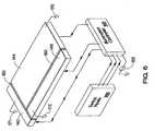
- FIG 6is an isometric view of an additional light-emitting layer that can be positioned beneath light-emitting layer 40 of Figure 2 in accordance with a preferred embodiment of the invention.
- insulating material 180which can be also be a dielectric material such as barium titanate, has been applied to the additional light-emitting layer in order to provide three separate illumination zones.
- each illumination zoneis controlled by way of a separate output from illumination controller 168.
- signal grounds 170, 171, and 172provide the necessary relative ground for each alternating or direct current signal applied to the three illumination zones by way of light-emitting controller 168.
- switch inputs 160 and illumination controller 168are used to control the excitation of each of the three zones shown in Figure 6.
- the arrangement of Figure 6allows independent control over light generated from each of the three illumination zones shown in the figure.
- one of switch inputs 160can be used to generate light visible through illumination zone 146, thus providing light to a small portion of touch pad 7.
- one of switch inputs 160can be used to illuminate a relatively small portion of the right side of the touch pad.
- this illumination schemecan be used to indicate that the touch pad is being used to control a scroll bar visible on an associated computer display.
- this illumination schemecan be used to indicate that touch pad 7 is being used to control a horizontal scroll bar.
- illumination zones 142 and 146can be used to indicate touch pad 7 is being used to move or pan the view of the display within a larger area.
- illumination of illumination zones 144, 142, and 146can be used to indicate the normal operation of the touch pad.
- FIG. 7is an isometric view of a light-emitting layer that provides a graphics capability constructed in accordance with a preferred embodiment of the invention.
- the light-emitting layer of Figure 7has been partitioned to provide numerous illumination zones, each of which can be separately controlled by way of illumination controller 268.
- each illumination zoneincludes a light-emitting material 246 similar to light-emitting material 46 of Figures 2 and 5.
- illumination controller 268is shown as being coupled to the underside of a select few of illumination zones 24 ⁇ , although it is preferred that the controller be coupled to each zone to permit excitation of the underside of each zone.
- signal grounds 270are shown as being coupled to a select few of the top sides of illumination zones 240; however, it is preferred that one of signal grounds 270 be coupled to each of the top sides of illumination zones 240.
- insulating material 280has been applied to the interstices that exist between adjacent ones of illumination zones 240.
- This insulating materialallows the independent generation of light from each of illumination zones 240 as illumination controller 268 modulates excitation signals from voltage source 265.
- the electroluminescence layer of Figure 7can be used to generate graphics with a resolution commensurate with the size and number of illumination zones 240. Further, the activation and deactivation of illumination zones 240 can be modulated in a time dependent manner to create moving graphics.
- Figure 8shows a user's finger (8) being moved across a touch pad (7) while nearby illumination zones are activated.
- user's finger 8moves in the -y direction toward rear portion 6 of computing device 5.
- illumination zonessuch as illumination zones 240 of Figure 7 are shown as generating light, thus providing the user with visual feedback as to the position of his or her finger above touch pad 7.
- the illumination zonesno longer generate light, thus indicating to the user that the touch pad is no longer active.
- the usercan influence the persistence of the illuminated zones by way of interacting with a setup program that is executed by computing device 5. This allows the illumination zones to be illuminated for a variable period of time after the user's finger passes over the touch pad.
- the inverse of the illumination scheme of Figure 8is also possible. Accordingly, when a user selects to invert the touch pad illumination scheme, the pad is generally illuminated except in the area proximate to the current location of the user's finger. Desirably, the user can influence the persistence of the illuminated zones by way of a setup page, thus allowing the zones to be extinguished for a variable period of time after the user's finger passes over the touch pad.
- illumination zones 240can be made with much greater resolution than that shown in Figure 7. This increase in resolution, combined with the correct persistence in the illumination of illumination zones 240, brings about the capability for a user to view a complex character entered by way of the touch pad. Thus, when touch pad 7 is used to enter an alphabetic, pictographic, or other symbolic character, a trace of the entered character can remain illuminated on the touch pad.
- a touch padthat presents the appearance and performs the functions of the user-definable or "soft" keys (F1-F12 on many standard keyboards) is used to augment or to replace these keys.
- F1-F12on many standard keyboards
- applications that require input from these keyscan provide the user with the opportunity to make use of the touch pad to enter this information.
- other applicationsthat occasionally present a window that notifies the user of a specific, required action can present this information by way of the touch pad.
- the touch padcan then be used to receive the required input, thus providing the user with another means of entering the required information.
- each layerneed not encompass the entire area of the touch pad.
- a particular layercan be limited to one side of the pad and become illuminated when the pad is used to control a vertical scroll bar.
- Another layercan be limited to the bottom of the touch pad (in the direction of rear portion 6 of the computing device of Figure 8) in order to provide feedback when the touch pad is being used to control a horizontal scroll bar.
- yet another layercan be added to present a symbol, such as a trademark, logo, or other statement that conveys the identity of the manufacturer of the touch pad or of the computing device.
- a lighted touch padthat presents feedback to user inputs provides a method and apparatus for indicating the operating state of the touch pad.
- the lighted touch padcan be used in conjunction with conventional capacitive or resistive sensor arrays that report the position of a user's finger or thumb on the surface of the touch pad. Aside from providing illumination of the entire touch pad surface by way of a single light-emitting layer, multiple layers can provide additional colors, graphics, and illumination of sections that indicate specific modes of operation.
Landscapes
- Engineering & Computer Science (AREA)
- General Engineering & Computer Science (AREA)
- Theoretical Computer Science (AREA)
- Human Computer Interaction (AREA)
- Physics & Mathematics (AREA)
- General Physics & Mathematics (AREA)
- Position Input By Displaying (AREA)
- Input From Keyboards Or The Like (AREA)
- User Interface Of Digital Computer (AREA)
Abstract
Description
Claims (10)
- A device used to accept an operator input to a computing device (5),comprising:a first layer which includes a translucent cover (10);a second layer which includes a plurality of surfaces (22), said surfaces beingone of a capacitive or resistive surface and being constructed using a translucent andconductive material; anda third layer which includes a light-emitting material (46) which generateslight in response to said operator input.
- The device of claim 1 wherein said operator input is one of a user's finger(8) and thumb positioned at a location near a side of said first layer, said side beingopposite said second layer, said operator input being used to control an aspect of acomputer display (38) controlled by said computing device (5).
- The device of claim 2 wherein said plurality of surfaces (22) function byresponding to changes in capacitance between adjacent ones of said plurality ofsurfaces (22).
- The device of claim 1 further comprising a fourth layer which generateslight of a different color than light generated by said third layer.
- The device of claim 1 wherein said computing device (5) launches asoftware application that runs on said computing device (5) in response to saidoperator input.
- The device of claim 1 wherein said light-emitting material (46) generateslight that persists for a period of time after one of a user's finger (8) and thumb hasbeen positioned at a location on the top side of said first layer, said light beinggenerated only in an area proximate to said location.
- The device of claim 1 wherein said light-emitting material (46) generateslight that persists for a period of time after one of a user's finger (8) and thumb hasbeen positioned at a location on the top side of said first layer, said light beinggenerated in areas other than an area proximate to said location.
- A graphical pointing device used to position an icon on a display (38),comprising:means for determining the position of a user's finger (8) near a top side of saidgraphical pointing device, at least a portion of said means for determining saidposition being predominantly translucent; andmeans for illuminating said graphical pointing device, said means forilluminating being near a bottom side of said graphical pointing device.
- The graphical pointing device of claim 8, wherein said at least a portion ofsaid means for determining said position is transparent.
- The graphical pointing device of claim 8, wherein said means forilluminating said graphical pointing device is translucent, and wherein said graphicalpointing device further comprises a second means for illuminating, said second meansfor illuminating being used to generate light of a different color than said first meansfor illuminating.
Applications Claiming Priority (2)
| Application Number | Priority Date | Filing Date | Title |
|---|---|---|---|
| US829692 | 2001-04-10 | ||
| US09/829,692US6822640B2 (en) | 2001-04-10 | 2001-04-10 | Illuminated touch pad |
Publications (3)
| Publication Number | Publication Date |
|---|---|
| EP1251455A2true EP1251455A2 (en) | 2002-10-23 |
| EP1251455A3 EP1251455A3 (en) | 2003-09-10 |
| EP1251455B1 EP1251455B1 (en) | 2006-06-21 |
Family
ID=25255270
Family Applications (1)
| Application Number | Title | Priority Date | Filing Date |
|---|---|---|---|
| EP02252106AExpired - LifetimeEP1251455B1 (en) | 2001-04-10 | 2002-03-22 | Illuminated touch pad |
Country Status (4)
| Country | Link |
|---|---|
| US (2) | US6822640B2 (en) |
| EP (1) | EP1251455B1 (en) |
| JP (1) | JP4105884B2 (en) |
| DE (1) | DE60212490T2 (en) |
Cited By (41)
| Publication number | Priority date | Publication date | Assignee | Title |
|---|---|---|---|---|
| WO2004114105A3 (en)* | 2003-06-14 | 2005-09-15 | Ronald Peter Binstead | Improvements in touch technology |
| WO2006135127A1 (en) | 2005-06-14 | 2006-12-21 | Melfas, Inc. | Apparatus for controlling digital device based on touch input interface capable of visual input feedback and method for the same |
| EP1761002A1 (en)* | 2005-08-30 | 2007-03-07 | LG Electronics Inc. | Touch key assembly for a mobile terminal |
| WO2007078478A1 (en)* | 2005-12-30 | 2007-07-12 | Apple Inc. | Illuminated touchpad |
| EP1852771A2 (en)* | 2006-05-03 | 2007-11-07 | LG Electronics Inc. | Mobile communication terminal and method of processing key signal |
| US7333092B2 (en) | 2002-02-25 | 2008-02-19 | Apple Computer, Inc. | Touch pad for handheld device |
| US7348967B2 (en) | 2001-10-22 | 2008-03-25 | Apple Inc. | Touch pad for handheld device |
| WO2008045414A1 (en)* | 2006-10-06 | 2008-04-17 | Kyocera Wireless Corp. | Navigation pad and method of using same |
| GB2446468A (en)* | 2007-02-12 | 2008-08-13 | Me2B Holdings Ltd | Touchpad With A Plurality Of Display Elements Located In The Touchpad Area |
| US7495659B2 (en) | 2003-11-25 | 2009-02-24 | Apple Inc. | Touch pad for handheld device |
| US7499040B2 (en) | 2003-08-18 | 2009-03-03 | Apple Inc. | Movable touch pad with added functionality |
| EP1927917A3 (en)* | 2006-11-28 | 2009-08-19 | SMK Corporation | Noncontact input apparatus |
| WO2009095848A3 (en)* | 2008-01-29 | 2009-09-24 | Philips Intellectual Property & Standards Gmbh | Oled illumination device with integrated proximity sensor |
| US7671837B2 (en) | 2005-09-06 | 2010-03-02 | Apple Inc. | Scrolling input arrangements using capacitive sensors on a flexible membrane |
| US7710394B2 (en) | 2001-10-22 | 2010-05-04 | Apple Inc. | Method and apparatus for use of rotational user inputs |
| US7710393B2 (en) | 2001-10-22 | 2010-05-04 | Apple Inc. | Method and apparatus for accelerated scrolling |
| US7795553B2 (en) | 2006-09-11 | 2010-09-14 | Apple Inc. | Hybrid button |
| US7825907B2 (en) | 2005-08-30 | 2010-11-02 | Lg Electronics Inc. | Touch key assembly for a mobile terminal |
| US7880729B2 (en) | 2005-10-11 | 2011-02-01 | Apple Inc. | Center button isolation ring |
| US7910843B2 (en) | 2007-09-04 | 2011-03-22 | Apple Inc. | Compact input device |
| US7932897B2 (en) | 2004-08-16 | 2011-04-26 | Apple Inc. | Method of increasing the spatial resolution of touch sensitive devices |
| AU2006333471B2 (en)* | 2005-12-30 | 2011-06-16 | Apple Inc. | Touch pad with symbols based on mode |
| US7982718B2 (en) | 2005-08-30 | 2011-07-19 | Lg Electronics Inc. | Mobile terminal with back-lighted directional keys |
| US8022935B2 (en) | 2006-07-06 | 2011-09-20 | Apple Inc. | Capacitance sensing electrode with integrated I/O mechanism |
| US8059099B2 (en) | 2006-06-02 | 2011-11-15 | Apple Inc. | Techniques for interactive input to portable electronic devices |
| US8125461B2 (en) | 2008-01-11 | 2012-02-28 | Apple Inc. | Dynamic input graphic display |
| DE102011017383A1 (en)* | 2011-04-18 | 2012-10-18 | Ident Technology Ag | OLED interface |
| US8395590B2 (en) | 2008-12-17 | 2013-03-12 | Apple Inc. | Integrated contact switch and touch sensor elements |
| US8416198B2 (en) | 2007-12-03 | 2013-04-09 | Apple Inc. | Multi-dimensional scroll wheel |
| US8482530B2 (en) | 2006-11-13 | 2013-07-09 | Apple Inc. | Method of capacitively sensing finger position |
| US8514185B2 (en) | 2006-07-06 | 2013-08-20 | Apple Inc. | Mutual capacitance touch sensing device |
| CN102043550B (en)* | 2009-10-12 | 2013-09-25 | 晨星软件研发(深圳)有限公司 | Capacitive touch sensing device and method |
| US8743060B2 (en) | 2006-07-06 | 2014-06-03 | Apple Inc. | Mutual capacitance touch sensing device |
| US8816967B2 (en) | 2008-09-25 | 2014-08-26 | Apple Inc. | Capacitive sensor having electrodes arranged on the substrate and the flex circuit |
| US8820133B2 (en) | 2008-02-01 | 2014-09-02 | Apple Inc. | Co-extruded materials and methods |
| US8872771B2 (en) | 2009-07-07 | 2014-10-28 | Apple Inc. | Touch sensing device having conductive nodes |
| US9354751B2 (en) | 2009-05-15 | 2016-05-31 | Apple Inc. | Input device with optimized capacitive sensing |
| US9454256B2 (en) | 2008-03-14 | 2016-09-27 | Apple Inc. | Sensor configurations of an input device that are switchable based on mode |
| US9654104B2 (en) | 2007-07-17 | 2017-05-16 | Apple Inc. | Resistive force sensor with capacitive discrimination |
| US10180732B2 (en) | 2006-10-11 | 2019-01-15 | Apple Inc. | Gimballed scroll wheel |
| US10866718B2 (en) | 2007-09-04 | 2020-12-15 | Apple Inc. | Scrolling techniques for user interfaces |
Families Citing this family (133)
| Publication number | Priority date | Publication date | Assignee | Title |
|---|---|---|---|---|
| US7730401B2 (en) | 2001-05-16 | 2010-06-01 | Synaptics Incorporated | Touch screen with user interface enhancement |
| US7106307B2 (en)* | 2001-05-24 | 2006-09-12 | Eastman Kodak Company | Touch screen for use with an OLED display |
| JP4630502B2 (en)* | 2001-08-30 | 2011-02-09 | キヤノン株式会社 | Image forming apparatus and control method thereof |
| US7294059B2 (en)* | 2001-09-10 | 2007-11-13 | Igt | Gaming apparatus having touch pad input |
| US20070085841A1 (en)* | 2001-10-22 | 2007-04-19 | Apple Computer, Inc. | Method and apparatus for accelerated scrolling |
| US7215813B2 (en)* | 2001-12-03 | 2007-05-08 | Apple Computer, Inc. | Method and apparatus for color correction |
| US6980777B2 (en)* | 2002-07-31 | 2005-12-27 | Nokia Corporation | Smart pouch cover for mobile device |
| US20040187184A1 (en)* | 2003-03-27 | 2004-09-30 | Rubin Aaron Cole | Apparel articles including flexible personal device and information displays |
| US7382360B2 (en)* | 2003-04-15 | 2008-06-03 | Synaptics Incorporated | Methods and systems for changing the appearance of a position sensor with a light effect |
| US7884804B2 (en) | 2003-04-30 | 2011-02-08 | Microsoft Corporation | Keyboard with input-sensitive display device |
| US7119794B2 (en)* | 2003-04-30 | 2006-10-10 | Microsoft Corporation | Character and text unit input correction system |
| DE10326684A1 (en)* | 2003-06-03 | 2004-12-23 | Ego Control Systems Gmbh + Co. Kg | sensor device |
| US20060181517A1 (en)* | 2005-02-11 | 2006-08-17 | Apple Computer, Inc. | Display actuator |
| US7324652B2 (en)* | 2003-12-30 | 2008-01-29 | Starkey Laboratories, Inc. | Hearing aid having a supply source providing multiple supply voltages |
| US20050151727A1 (en)* | 2004-01-08 | 2005-07-14 | Intel Corporation | Wireless enabled touch pad pointing device with integrated remote control function |
| US20050172785A1 (en)* | 2004-02-02 | 2005-08-11 | Fisher-Robbins Holly E. | Musical instrument |
| TW200540490A (en)* | 2004-05-05 | 2005-12-16 | Koninkl Philips Electronics Nv | Lighting device with user interface for light control |
| JP2006018546A (en)* | 2004-07-01 | 2006-01-19 | Alps Electric Co Ltd | Input device |
| US20060001655A1 (en)* | 2004-07-01 | 2006-01-05 | Koji Tanabe | Light-transmitting touch panel and detection device |
| CA2519960A1 (en)* | 2004-09-15 | 2006-03-15 | Ludington Technologies, Inc. | Universal control adapter system |
| KR100577273B1 (en) | 2004-11-10 | 2006-05-10 | 엘지전자 주식회사 | Touchpad with travel direction indicator |
| EP1833700B1 (en)* | 2004-12-23 | 2011-07-13 | TouchSensor Technologies, L.L.C. | Seat control system |
| JP2008533559A (en)* | 2005-02-09 | 2008-08-21 | サーク・コーポレーション | Touchpad integrated into keyboard keycaps to improve user interaction |
| US20060214016A1 (en)* | 2005-03-18 | 2006-09-28 | Edward Erdely | Hands-free faucet |
| JP2006330790A (en)* | 2005-05-23 | 2006-12-07 | Alps Electric Co Ltd | Coordinate input device and terminal device equipped with same |
| US20070063876A1 (en)* | 2005-08-24 | 2007-03-22 | Wong Alex K | Multiple sensing element touch sensor |
| US20070068786A1 (en)* | 2005-09-21 | 2007-03-29 | Lear Corporation | Touch pad having integrated lighting feature and touch sensor and method of operating the same |
| JP2007133698A (en)* | 2005-11-10 | 2007-05-31 | Sony Ericsson Mobilecommunications Japan Inc | Portable terminal |
| KR100700143B1 (en) | 2005-12-02 | 2007-03-28 | 엘지전자 주식회사 | Key selection display device of touch keypad and method |
| US8421755B2 (en)* | 2006-01-17 | 2013-04-16 | World Properties, Inc. | Capacitive touch sensor with integral EL backlight |
| US7538760B2 (en)* | 2006-03-30 | 2009-05-26 | Apple Inc. | Force imaging input device and system |
| TWI356630B (en)* | 2006-04-17 | 2012-01-11 | Panasonic Corp | Input device, electronic apparatus and method for |
| KR100846188B1 (en)* | 2006-08-08 | 2008-07-14 | (주)멜파스 | A user input device having a plurality of touch sensors, and a method for controlling a digital device by detecting a user's contact from the device |
| FR2905195B1 (en)* | 2006-08-23 | 2008-10-10 | Dav Sa | CONTROL MODULE, IN PARTICULAR FOR MOTOR VEHICLE |
| US20080088600A1 (en)* | 2006-10-11 | 2008-04-17 | Apple Inc. | Method and apparatus for implementing multiple push buttons in a user input device |
| US20080088597A1 (en)* | 2006-10-11 | 2008-04-17 | Apple Inc. | Sensor configurations in a user input device |
| US7755615B2 (en)* | 2006-12-18 | 2010-07-13 | Motorola, Inc. | Optical shuttered touchscreen and method therefor |
| US20080204412A1 (en)* | 2007-02-22 | 2008-08-28 | Peter On | User interface navigation mechanism and method of using the same |
| US7979315B2 (en)* | 2007-03-14 | 2011-07-12 | Microsoft Corporation | Virtual features of physical items |
| TWI339806B (en)* | 2007-04-04 | 2011-04-01 | Htc Corp | Electronic device capable of executing commands therein and method for executing commands in the same |
| US20080266272A1 (en)* | 2007-04-26 | 2008-10-30 | World Properties, Inc. | Luminous touch sensor |
| EP1995992A3 (en)* | 2007-05-24 | 2009-12-02 | Starkey Laboratories, Inc. | Hearing assistance device with capacitive switch |
| US20090058801A1 (en)* | 2007-09-04 | 2009-03-05 | Apple Inc. | Fluid motion user interface control |
| US20090073130A1 (en)* | 2007-09-17 | 2009-03-19 | Apple Inc. | Device having cover with integrally formed sensor |
| JP4551923B2 (en)* | 2007-11-30 | 2010-09-29 | 株式会社東芝 | Electronics |
| US20090179870A1 (en)* | 2008-01-16 | 2009-07-16 | World Properties, Inc. | Luminous touch screen with interstitial layers |
| JP4918529B2 (en)* | 2008-07-24 | 2012-04-18 | 陞達科技股▲ふん▼有限公司 | Integrated input system |
| US20100058251A1 (en)* | 2008-08-27 | 2010-03-04 | Apple Inc. | Omnidirectional gesture detection |
| US7782133B2 (en)* | 2008-09-03 | 2010-08-24 | Infineon Technologies Ag | Power amplifier with output power control |
| US20100060568A1 (en)* | 2008-09-05 | 2010-03-11 | Apple Inc. | Curved surface input device with normalized capacitive sensing |
| TW201025391A (en)* | 2008-12-22 | 2010-07-01 | Asustek Comp Inc | Mobile electric device with touch illumination and touch illumination method thereof |
| WO2010078321A1 (en) | 2008-12-29 | 2010-07-08 | Otter Products, Llc | Protective cushion cover for an electronic device |
| TW201025101A (en)* | 2008-12-31 | 2010-07-01 | Asustek Comp Inc | Touch pad and electronic device |
| US9703411B2 (en) | 2009-04-30 | 2017-07-11 | Synaptics Incorporated | Reduction in latency between user input and visual feedback |
| DE102009036162A1 (en)* | 2009-07-28 | 2011-02-03 | E.G.O. Elektro-Gerätebau GmbH | Sensor element means |
| US8965458B2 (en) | 2009-08-21 | 2015-02-24 | Otter Products, Llc | Protective cushion cover for an electronic device |
| US8179376B2 (en)* | 2009-08-27 | 2012-05-15 | Research In Motion Limited | Touch-sensitive display with capacitive and resistive touch sensors and method of control |
| US20110091058A1 (en)* | 2009-10-16 | 2011-04-21 | Starkey Laboratories, Inc. | Method and apparatus for in-the-ear hearing aid with capacitive sensor |
| DK2348758T3 (en)* | 2009-10-17 | 2019-09-23 | Starkey Labs Inc | Method and device for rear-ear hearing aid with capacitive sensor |
| US8982063B2 (en) | 2010-02-25 | 2015-03-17 | Blackberry Limited | Optical naviagation module having a metallic illumination ring |
| US20110205179A1 (en)* | 2010-02-25 | 2011-08-25 | Research In Motion Limited | Three-dimensional illuminated area for optical navigation |
| US8937598B2 (en)* | 2010-02-25 | 2015-01-20 | Blackberry Limited | Illuminated optical navigation module |
| US9025317B2 (en) | 2010-03-17 | 2015-05-05 | Otter Products, Llc | Multi-material protective case for sliding/articulating/rotating handheld electronic devices |
| US8866744B2 (en)* | 2010-03-30 | 2014-10-21 | Howay Corp. | Keyboard having touch input device |
| DE102011006448A1 (en) | 2010-03-31 | 2011-10-06 | Tk Holdings, Inc. | steering wheel sensors |
| US8587422B2 (en) | 2010-03-31 | 2013-11-19 | Tk Holdings, Inc. | Occupant sensing system |
| DE102011006649B4 (en) | 2010-04-02 | 2018-05-03 | Tk Holdings Inc. | Steering wheel with hand sensors |
| US9089367B2 (en) | 2010-04-08 | 2015-07-28 | Alcon Research, Ltd. | Patient eye level touch control |
| CN102971635A (en) | 2010-05-10 | 2013-03-13 | 普尔想象力有限责任公司 | One sided thin film capacitive touch sensors |
| US8339288B2 (en) | 2010-06-10 | 2012-12-25 | Intellectual Discovery Co., Ltd. | Light guide having a capacitive sensing grid for a keypad and related methodology |
| US20110304542A1 (en)* | 2010-06-10 | 2011-12-15 | Isaac Calderon | Multi purpose remote control with display |
| US8471138B2 (en) | 2010-06-17 | 2013-06-25 | Pure Imagination, LLC | Musical instrument with one sided thin film capacitive touch sensors |
| US9092096B2 (en)* | 2010-07-26 | 2015-07-28 | Pure Imagination, LLC | Low-cost mass-produced touch sensors |
| US8378203B2 (en) | 2010-07-27 | 2013-02-19 | Pure Imagination, LLC | Simulated percussion instrument |
| US8317542B2 (en) | 2010-09-30 | 2012-11-27 | Apple Inc. | High-speed card connector |
| MX2013003563A (en) | 2010-09-30 | 2013-06-28 | Apple Inc | PORTABLE COMPUTATION DEVICE. |
| WO2012042493A1 (en) | 2010-09-30 | 2012-04-05 | Koninklijke Philips Electronics N.V. | System for amplitude adjustment of an oral care appliance |
| KR101793313B1 (en) | 2010-10-12 | 2017-11-02 | 트리프로그 디벨롭먼츠, 인크. | Housing for encasing an electronic device |
| US9549598B2 (en) | 2010-10-12 | 2017-01-24 | Treefrog Developments, Inc. | Housing for encasing an electronic device |
| MX2013004374A (en)* | 2010-10-18 | 2013-05-22 | Apple Inc | Portable computer with reveal region. |
| US8866735B2 (en)* | 2010-12-16 | 2014-10-21 | Motorla Mobility LLC | Method and apparatus for activating a function of an electronic device |
| JP5118217B2 (en)* | 2011-02-02 | 2013-01-16 | 株式会社東海理化電機製作所 | controller |
| USD687831S1 (en)* | 2011-02-12 | 2013-08-13 | Samsung Electronics Co., Ltd. | Notebook computer |
| DE102011014872B4 (en)* | 2011-03-23 | 2017-04-13 | Continental Automotive Gmbh | operating device |
| TWI446240B (en)* | 2011-06-03 | 2014-07-21 | Primax Electronics Ltd | Input device with light patterns |
| CN105843331B (en) | 2011-06-13 | 2019-06-14 | 树蛙开发公司 | Case to protect tablet |
| US9615476B2 (en) | 2011-06-13 | 2017-04-04 | Treefrog Developments, Inc. | Housing for encasing a mobile device |
| USD736777S1 (en) | 2012-06-13 | 2015-08-18 | Treefrog Developments, Inc. | Case for an electronic device |
| CN102830828A (en)* | 2011-06-17 | 2012-12-19 | 致伸科技股份有限公司 | Input device with luminous pattern |
| TWI471773B (en)* | 2011-08-12 | 2015-02-01 | Wintek Corp | Touch-sensing panel and touch-sensing display apparatus |
| EP3193456B1 (en) | 2011-12-22 | 2018-12-12 | TreeFrog Developments, Inc. | Accessories for use with housing for an electronic device |
| US9204697B2 (en) | 2012-01-10 | 2015-12-08 | The Joy Factory, Inc. | Protective casing providing impact absorption and water resistance for portable electronic devices |
| WO2013154720A1 (en) | 2012-04-13 | 2013-10-17 | Tk Holdings Inc. | Pressure sensor including a pressure sensitive material for use with control systems and methods of using the same |
| US9469469B2 (en) | 2012-06-01 | 2016-10-18 | Treefrog Developments, Inc. | Housing for encasing an object having a thin profile |
| US9241551B2 (en) | 2012-06-13 | 2016-01-26 | Otter Products, Llc | Protective case with compartment |
| US9493342B2 (en) | 2012-06-21 | 2016-11-15 | Nextinput, Inc. | Wafer level MEMS force dies |
| EP2870445A1 (en) | 2012-07-05 | 2015-05-13 | Ian Campbell | Microelectromechanical load sensor and methods of manufacturing the same |
| CA2880430A1 (en) | 2012-07-30 | 2014-02-06 | Treefrog Developments, Inc. | Weatherproof loudspeaker and speaker assembly |
| US20140070933A1 (en)* | 2012-09-07 | 2014-03-13 | GM Global Technology Operations LLC | Vehicle user control system and method of performing a vehicle command |
| WO2014043664A1 (en) | 2012-09-17 | 2014-03-20 | Tk Holdings Inc. | Single layer force sensor |
| JP6020037B2 (en)* | 2012-10-25 | 2016-11-02 | 大日本印刷株式会社 | Touch switch element and touch switch device |
| JP6145634B2 (en)* | 2013-03-29 | 2017-06-14 | 株式会社コナミデジタルエンタテインメント | Input system, operation input method, and computer program |
| EP2996513B1 (en) | 2013-05-18 | 2018-03-28 | Otter Products, LLC | Waterproof protective case for an electronic device |
| US9300078B2 (en) | 2013-08-23 | 2016-03-29 | Otter Products, Llc | Waterproof housing for mobile electronic device and waterproof adapter for accessory device |
| JP6253923B2 (en)* | 2013-08-30 | 2017-12-27 | 株式会社ジャパンディスプレイ | Organic electroluminescence device with built-in touch sensor |
| EP3094950B1 (en) | 2014-01-13 | 2022-12-21 | Nextinput, Inc. | Miniaturized and ruggedized wafer level mems force sensors |
| DE102014113732B4 (en)* | 2014-09-23 | 2022-11-24 | Pictiva Displays International Limited | 3D OLED and method of making a 3D OLED |
| US10963117B2 (en) | 2014-09-30 | 2021-03-30 | Apple Inc. | Configurable force-sensitive input structure for electronic devices |
| DE202014105755U1 (en)* | 2014-11-28 | 2016-03-01 | Zumtobel Lighting Gmbh | Operating device for generating control information for the control of consumers |
| US9577697B2 (en) | 2015-05-27 | 2017-02-21 | Otter Products, Llc | Protective case with stylus access feature |
| CN107848788B (en) | 2015-06-10 | 2023-11-24 | 触控解决方案股份有限公司 | Ruggedized wafer-level MEMS force sensor with tolerance trench |
| TWI649686B (en) | 2015-09-30 | 2019-02-01 | 美商蘋果公司 | Keyboard with adaptive input columns |
| US10409412B1 (en) | 2015-09-30 | 2019-09-10 | Apple Inc. | Multi-input element for electronic device |
| US9960521B2 (en) | 2016-02-24 | 2018-05-01 | Otter Products, Llc | Connector for fluidly sealing an aperture of a protective case |
| US10295612B2 (en)* | 2016-04-05 | 2019-05-21 | Apple Inc. | Electronic device with resistive sensor array |
| DE102016108262A1 (en)* | 2016-05-04 | 2017-11-09 | Osram Oled Gmbh | Light-emitting assembly and method for operating a light-emitting assembly |
| US10318065B2 (en) | 2016-08-03 | 2019-06-11 | Apple Inc. | Input device having a dimensionally configurable input area |
| US10178902B2 (en) | 2016-09-07 | 2019-01-15 | Otter Products, Llc | Protective enclosure for encasing an electronic device |
| US10871860B1 (en) | 2016-09-19 | 2020-12-22 | Apple Inc. | Flexible sensor configured to detect user inputs |
| US11243125B2 (en) | 2017-02-09 | 2022-02-08 | Nextinput, Inc. | Integrated piezoresistive and piezoelectric fusion force sensor |
| EP3580539A4 (en) | 2017-02-09 | 2020-11-25 | Nextinput, Inc. | INTEGRATED DIGITAL FORCE SENSORS AND RELATED METHOD OF MANUFACTURING |
| US11096850B2 (en) | 2017-06-27 | 2021-08-24 | Stryker Corporation | Patient support apparatus control systems |
| US10732743B2 (en) | 2017-07-18 | 2020-08-04 | Apple Inc. | Concealable input region for an electronic device having microperforations |
| US11221263B2 (en) | 2017-07-19 | 2022-01-11 | Nextinput, Inc. | Microelectromechanical force sensor having a strain transfer layer arranged on the sensor die |
| WO2019023309A1 (en) | 2017-07-25 | 2019-01-31 | Nextinput, Inc. | Integrated fingerprint and force sensor |
| WO2019023552A1 (en) | 2017-07-27 | 2019-01-31 | Nextinput, Inc. | A wafer bonded piezoresistive and piezoelectric force sensor and related methods of manufacture |
| US10732676B2 (en) | 2017-09-06 | 2020-08-04 | Apple Inc. | Illuminated device enclosure with dynamic trackpad |
| WO2019079420A1 (en) | 2017-10-17 | 2019-04-25 | Nextinput, Inc. | Temperature coefficient of offset compensation for force sensor and strain gauge |
| WO2019090057A1 (en) | 2017-11-02 | 2019-05-09 | Nextinput, Inc. | Sealed force sensor with etch stop layer |
| WO2019099821A1 (en) | 2017-11-16 | 2019-05-23 | Nextinput, Inc. | Force attenuator for force sensor |
| US10827809B2 (en) | 2018-04-05 | 2020-11-10 | Otter Products, Llc | Protective case for electronic device |
| US10962427B2 (en) | 2019-01-10 | 2021-03-30 | Nextinput, Inc. | Slotted MEMS force sensor |
| DE202021002012U1 (en) | 2021-06-09 | 2021-06-22 | Claus Linder | Steering wheel with a touchscreen control element for motor vehicles or e-cars, e-cars, trucks, electric trucks or construction machines |
Family Cites Families (18)
| Publication number | Priority date | Publication date | Assignee | Title |
|---|---|---|---|---|
| US5153386A (en)* | 1989-05-10 | 1992-10-06 | Summagraphics Corporation | Digitizer tablet with illuminable working surface |
| US5132681A (en)* | 1989-07-05 | 1992-07-21 | Ryoichi Yabe | Intelligent switch system |
| DE68928987T2 (en) | 1989-10-02 | 1999-11-11 | Koninkl Philips Electronics Nv | Data processing system with a touch display and a digitizing tablet, both integrated in an input device |
| DE69324067T2 (en) | 1992-06-08 | 1999-07-15 | Synaptics Inc | Object position detector |
| US5359155A (en)* | 1993-03-25 | 1994-10-25 | Tiger Scientific Corp. | Illumination apparatus for a digitizer tablet |
| KR200151013Y1 (en) | 1993-04-20 | 1999-07-15 | 손욱 | Digitizer |
| US5736686A (en)* | 1995-03-01 | 1998-04-07 | Gtco Corporation | Illumination apparatus for a digitizer tablet with improved light panel |
| US5560696A (en)* | 1995-04-07 | 1996-10-01 | Orlich; William N. | Method and apparatus for establishing an alignment grid or pattern |
| US5748185A (en)* | 1996-07-03 | 1998-05-05 | Stratos Product Development Group | Touchpad with scroll and pan regions |
| US5747756A (en) | 1996-09-10 | 1998-05-05 | Gm Nameplate, Inc. | Electroluminescent backlit keypad |
| US6061051A (en)* | 1997-01-17 | 2000-05-09 | Tritech Microelectronics | Command set for touchpad pen-input mouse |
| US6118435A (en)* | 1997-04-10 | 2000-09-12 | Idec Izumi Corporation | Display unit with touch panel |
| US6215476B1 (en)* | 1997-10-10 | 2001-04-10 | Apple Computer, Inc. | Flat panel display with integrated electromagnetic pen digitizer |
| US8089470B1 (en) | 1998-10-20 | 2012-01-03 | Synaptics Incorporated | Finger/stylus touch pad |
| JP2001076582A (en)* | 1999-09-01 | 2001-03-23 | Matsushita Electric Ind Co Ltd | Electronics |
| US6462941B1 (en)* | 2000-06-30 | 2002-10-08 | Palm, Inc. | Method and apparatus for backlighting a handwriting input area for a portable computing device |
| US6587097B1 (en)* | 2000-11-28 | 2003-07-01 | 3M Innovative Properties Co. | Display system |
| EP1227388A1 (en)* | 2001-01-24 | 2002-07-31 | Inventec Appliances Corp. | Construction of touch screen |
- 2001
- 2001-04-10USUS09/829,692patent/US6822640B2/ennot_activeExpired - Lifetime
- 2002
- 2002-03-22DEDE60212490Tpatent/DE60212490T2/ennot_activeExpired - Lifetime
- 2002-03-22EPEP02252106Apatent/EP1251455B1/ennot_activeExpired - Lifetime
- 2002-04-08JPJP2002104879Apatent/JP4105884B2/ennot_activeExpired - Lifetime
- 2003
- 2003-07-07USUS10/616,357patent/US20040027341A1/ennot_activeAbandoned
Cited By (70)
| Publication number | Priority date | Publication date | Assignee | Title |
|---|---|---|---|---|
| US7348967B2 (en) | 2001-10-22 | 2008-03-25 | Apple Inc. | Touch pad for handheld device |
| US9009626B2 (en) | 2001-10-22 | 2015-04-14 | Apple Inc. | Method and apparatus for accelerated scrolling |
| US9977518B2 (en) | 2001-10-22 | 2018-05-22 | Apple Inc. | Scrolling based on rotational movement |
| US7710409B2 (en) | 2001-10-22 | 2010-05-04 | Apple Inc. | Method and apparatus for use of rotational user inputs |
| US7710393B2 (en) | 2001-10-22 | 2010-05-04 | Apple Inc. | Method and apparatus for accelerated scrolling |
| US7710394B2 (en) | 2001-10-22 | 2010-05-04 | Apple Inc. | Method and apparatus for use of rotational user inputs |
| US8952886B2 (en) | 2001-10-22 | 2015-02-10 | Apple Inc. | Method and apparatus for accelerated scrolling |
| US10353565B2 (en) | 2002-02-25 | 2019-07-16 | Apple Inc. | Input apparatus and button arrangement for handheld device |
| US7333092B2 (en) | 2002-02-25 | 2008-02-19 | Apple Computer, Inc. | Touch pad for handheld device |
| US8446370B2 (en) | 2002-02-25 | 2013-05-21 | Apple Inc. | Touch pad for handheld device |
| GB2418259B (en)* | 2003-06-14 | 2007-08-08 | Ronald Peter Binstead | Improvements in touch technology |
| GB2418259A (en)* | 2003-06-14 | 2006-03-22 | Ronald Peter Binstead | Improvements in touch technology |
| CN100472415C (en)* | 2003-06-14 | 2009-03-25 | 罗纳德·P·宾斯蒂德 | Improvements in touch technology |
| WO2004114105A3 (en)* | 2003-06-14 | 2005-09-15 | Ronald Peter Binstead | Improvements in touch technology |
| AU2006333374B2 (en)* | 2003-08-18 | 2010-11-04 | Apple Inc. | Illuminated input device |
| US7499040B2 (en) | 2003-08-18 | 2009-03-03 | Apple Inc. | Movable touch pad with added functionality |
| US8749493B2 (en) | 2003-08-18 | 2014-06-10 | Apple Inc. | Movable touch pad with added functionality |
| US8552990B2 (en) | 2003-11-25 | 2013-10-08 | Apple Inc. | Touch pad for handheld device |
| US7495659B2 (en) | 2003-11-25 | 2009-02-24 | Apple Inc. | Touch pad for handheld device |
| US8933890B2 (en) | 2003-11-25 | 2015-01-13 | Apple Inc. | Techniques for interactive input to portable electronic devices |
| US7932897B2 (en) | 2004-08-16 | 2011-04-26 | Apple Inc. | Method of increasing the spatial resolution of touch sensitive devices |
| EP1894080A4 (en)* | 2005-06-14 | 2009-05-27 | Melfas Inc | Apparatus for controlling digital device based on touch input interface capable of visual input feedback and method for the same |
| US8462122B2 (en) | 2005-06-14 | 2013-06-11 | Melfas, Inc. | Apparatus for controlling digital device based on touch input interface capable of visual input feedback and method for the same |
| WO2006135127A1 (en) | 2005-06-14 | 2006-12-21 | Melfas, Inc. | Apparatus for controlling digital device based on touch input interface capable of visual input feedback and method for the same |
| US7825907B2 (en) | 2005-08-30 | 2010-11-02 | Lg Electronics Inc. | Touch key assembly for a mobile terminal |
| EP1761002A1 (en)* | 2005-08-30 | 2007-03-07 | LG Electronics Inc. | Touch key assembly for a mobile terminal |
| US7982718B2 (en) | 2005-08-30 | 2011-07-19 | Lg Electronics Inc. | Mobile terminal with back-lighted directional keys |
| US8049728B2 (en) | 2005-08-30 | 2011-11-01 | Lg Electronics Inc. | Touch key assembly for a mobile terminal |
| US7671837B2 (en) | 2005-09-06 | 2010-03-02 | Apple Inc. | Scrolling input arrangements using capacitive sensors on a flexible membrane |
| US7880729B2 (en) | 2005-10-11 | 2011-02-01 | Apple Inc. | Center button isolation ring |
| GB2446996B (en)* | 2005-12-30 | 2009-10-21 | Apple Inc | Handheld computing device with an illuminated input device |
| AU2006333471B2 (en)* | 2005-12-30 | 2011-06-16 | Apple Inc. | Touch pad with symbols based on mode |
| WO2007078478A1 (en)* | 2005-12-30 | 2007-07-12 | Apple Inc. | Illuminated touchpad |
| GB2446996A (en)* | 2005-12-30 | 2008-08-27 | Apple Inc | Illuminated touchpad |
| US9367151B2 (en) | 2005-12-30 | 2016-06-14 | Apple Inc. | Touch pad with symbols based on mode |
| EP1852771A2 (en)* | 2006-05-03 | 2007-11-07 | LG Electronics Inc. | Mobile communication terminal and method of processing key signal |
| US8059099B2 (en) | 2006-06-02 | 2011-11-15 | Apple Inc. | Techniques for interactive input to portable electronic devices |
| US8022935B2 (en) | 2006-07-06 | 2011-09-20 | Apple Inc. | Capacitance sensing electrode with integrated I/O mechanism |
| US10139870B2 (en) | 2006-07-06 | 2018-11-27 | Apple Inc. | Capacitance sensing electrode with integrated I/O mechanism |
| US9360967B2 (en) | 2006-07-06 | 2016-06-07 | Apple Inc. | Mutual capacitance touch sensing device |
| US10359813B2 (en) | 2006-07-06 | 2019-07-23 | Apple Inc. | Capacitance sensing electrode with integrated I/O mechanism |
| US10890953B2 (en) | 2006-07-06 | 2021-01-12 | Apple Inc. | Capacitance sensing electrode with integrated I/O mechanism |
| US8514185B2 (en) | 2006-07-06 | 2013-08-20 | Apple Inc. | Mutual capacitance touch sensing device |
| US8743060B2 (en) | 2006-07-06 | 2014-06-03 | Apple Inc. | Mutual capacitance touch sensing device |
| US8044314B2 (en) | 2006-09-11 | 2011-10-25 | Apple Inc. | Hybrid button |
| US7795553B2 (en) | 2006-09-11 | 2010-09-14 | Apple Inc. | Hybrid button |
| WO2008045414A1 (en)* | 2006-10-06 | 2008-04-17 | Kyocera Wireless Corp. | Navigation pad and method of using same |
| US8786553B2 (en) | 2006-10-06 | 2014-07-22 | Kyocera Corporation | Navigation pad and method of using same |
| US10180732B2 (en) | 2006-10-11 | 2019-01-15 | Apple Inc. | Gimballed scroll wheel |
| US8482530B2 (en) | 2006-11-13 | 2013-07-09 | Apple Inc. | Method of capacitively sensing finger position |
| EP1927917A3 (en)* | 2006-11-28 | 2009-08-19 | SMK Corporation | Noncontact input apparatus |
| GB2446468A (en)* | 2007-02-12 | 2008-08-13 | Me2B Holdings Ltd | Touchpad With A Plurality Of Display Elements Located In The Touchpad Area |
| US9654104B2 (en) | 2007-07-17 | 2017-05-16 | Apple Inc. | Resistive force sensor with capacitive discrimination |
| US12159028B2 (en) | 2007-09-04 | 2024-12-03 | Apple Inc. | Scrolling techniques for user interfaces |
| US10866718B2 (en) | 2007-09-04 | 2020-12-15 | Apple Inc. | Scrolling techniques for user interfaces |
| US7910843B2 (en) | 2007-09-04 | 2011-03-22 | Apple Inc. | Compact input device |
| US8330061B2 (en) | 2007-09-04 | 2012-12-11 | Apple Inc. | Compact input device |
| US8416198B2 (en) | 2007-12-03 | 2013-04-09 | Apple Inc. | Multi-dimensional scroll wheel |
| US8125461B2 (en) | 2008-01-11 | 2012-02-28 | Apple Inc. | Dynamic input graphic display |
| WO2009095848A3 (en)* | 2008-01-29 | 2009-09-24 | Philips Intellectual Property & Standards Gmbh | Oled illumination device with integrated proximity sensor |
| RU2511567C2 (en)* | 2008-01-29 | 2014-04-10 | Конинклейке Филипс Электроникс Н.В. | Lighting facility based on organic light-emitting diodes (led) with in-built proximity sensor |
| US8319434B2 (en) | 2008-01-29 | 2012-11-27 | Koninklijke Philips Electronics N.V. | OLED illumination device with integrated proximity sensor |
| US8820133B2 (en) | 2008-02-01 | 2014-09-02 | Apple Inc. | Co-extruded materials and methods |
| US9454256B2 (en) | 2008-03-14 | 2016-09-27 | Apple Inc. | Sensor configurations of an input device that are switchable based on mode |
| US8816967B2 (en) | 2008-09-25 | 2014-08-26 | Apple Inc. | Capacitive sensor having electrodes arranged on the substrate and the flex circuit |
| US8395590B2 (en) | 2008-12-17 | 2013-03-12 | Apple Inc. | Integrated contact switch and touch sensor elements |
| US9354751B2 (en) | 2009-05-15 | 2016-05-31 | Apple Inc. | Input device with optimized capacitive sensing |
| US8872771B2 (en) | 2009-07-07 | 2014-10-28 | Apple Inc. | Touch sensing device having conductive nodes |
| CN102043550B (en)* | 2009-10-12 | 2013-09-25 | 晨星软件研发(深圳)有限公司 | Capacitive touch sensing device and method |
| DE102011017383A1 (en)* | 2011-04-18 | 2012-10-18 | Ident Technology Ag | OLED interface |
Also Published As
| Publication number | Publication date |
|---|---|
| US20040027341A1 (en) | 2004-02-12 |
| US20020145594A1 (en) | 2002-10-10 |
| EP1251455A3 (en) | 2003-09-10 |
| DE60212490D1 (en) | 2006-08-03 |
| JP4105884B2 (en) | 2008-06-25 |
| EP1251455B1 (en) | 2006-06-21 |
| JP2002312116A (en) | 2002-10-25 |
| DE60212490T2 (en) | 2007-01-11 |
| US6822640B2 (en) | 2004-11-23 |
Similar Documents
| Publication | Publication Date | Title |
|---|---|---|
| US6822640B2 (en) | Illuminated touch pad | |
| US7176885B2 (en) | Retaskable switch-indicator unit | |
| US7423635B2 (en) | Single-layer touchpad having touch zones | |
| US10268312B2 (en) | Electronic device having multi-functional human interface | |
| US8570298B2 (en) | Display/input device | |
| US8194040B2 (en) | Compact touch-type keyboard | |
| KR100725392B1 (en) | Key input device combined with a key display unit and a digital device providing the same | |
| TWI550441B (en) | Handwritten information inputting device and portable electronic apparatus including handwritten information inputting device | |
| JP6325576B2 (en) | Physical force capacity type touch sensor | |
| US20110148807A1 (en) | Human interface device and related methods | |
| CN100520683C (en) | Reconfigurable illuminated keypad | |
| US20020180707A1 (en) | Input device capable of button input and coordinate input on the same operating surface | |
| US20080272927A1 (en) | Illuminated feedback for a touchpad by providing a light source that is associated with a finger position on a touchpad | |
| CA2449447A1 (en) | System for disposing a proximity sensitive touchpad behind a mobile phone keymat | |
| US20110090150A1 (en) | Input processing device | |
| CN112470108A (en) | Mechanical keyboard overlay for touch screen | |
| US20060077187A1 (en) | Coordinate input apparatus having light-emission function and terminal apparatus having the same | |
| US20180292924A1 (en) | Input processing apparatus | |
| KR20090046587A (en) | Touch sensing device | |
| JP5108824B2 (en) | Input processing device | |
| JP3926108B2 (en) | Coordinate input device, keyboard input device, and electronic apparatus | |
| CN101587388A (en) | Touch screen and electric system applying same | |
| JP2005346402A (en) | Input device and electronic apparatus | |
| HK1084481A (en) | Single-layer touchpad having touch zones |
Legal Events
| Date | Code | Title | Description |
|---|---|---|---|
| PUAI | Public reference made under article 153(3) epc to a published international application that has entered the european phase | Free format text:ORIGINAL CODE: 0009012 | |
| AK | Designated contracting states | Kind code of ref document:A2 Designated state(s):AT BE CH CY DE DK ES FI FR GB GR IE IT LI LU MC NL PT SE TR | |
| AX | Request for extension of the european patent | Free format text:AL;LT;LV;MK;RO;SI | |
| PUAL | Search report despatched | Free format text:ORIGINAL CODE: 0009013 | |
| AK | Designated contracting states | Kind code of ref document:A3 Designated state(s):AT BE CH CY DE DK ES FI FR GB GR IE IT LI LU MC NL PT SE TR | |
| AX | Request for extension of the european patent | Extension state:AL LT LV MK RO SI | |
| RIC1 | Information provided on ipc code assigned before grant | Ipc:7G 06F 3/033 B Ipc:7G 06K 11/18 A | |
| 17P | Request for examination filed | Effective date:20031017 | |
| 17Q | First examination report despatched | Effective date:20031118 | |
| AKX | Designation fees paid | Designated state(s):DE FR GB | |
| GRAP | Despatch of communication of intention to grant a patent | Free format text:ORIGINAL CODE: EPIDOSNIGR1 | |
| RIC1 | Information provided on ipc code assigned before grant | Ipc:G06F 3/033 20060101AFI20060131BHEP | |
| GRAS | Grant fee paid | Free format text:ORIGINAL CODE: EPIDOSNIGR3 | |
| GRAA | (expected) grant | Free format text:ORIGINAL CODE: 0009210 | |
| AK | Designated contracting states | Kind code of ref document:B1 Designated state(s):DE FR GB | |
| REG | Reference to a national code | Ref country code:GB Ref legal event code:FG4D | |
| REF | Corresponds to: | Ref document number:60212490 Country of ref document:DE Date of ref document:20060803 Kind code of ref document:P | |
| ET | Fr: translation filed | ||
| PLBE | No opposition filed within time limit | Free format text:ORIGINAL CODE: 0009261 | |
| STAA | Information on the status of an ep patent application or granted ep patent | Free format text:STATUS: NO OPPOSITION FILED WITHIN TIME LIMIT | |
| 26N | No opposition filed | Effective date:20070322 | |
| REG | Reference to a national code | Ref country code:GB Ref legal event code:732E Free format text:REGISTERED BETWEEN 20120329 AND 20120404 | |
| REG | Reference to a national code | Ref country code:FR Ref legal event code:PLFP Year of fee payment:15 | |
| REG | Reference to a national code | Ref country code:FR Ref legal event code:PLFP Year of fee payment:16 | |
| REG | Reference to a national code | Ref country code:FR Ref legal event code:PLFP Year of fee payment:17 | |
| PGFP | Annual fee paid to national office [announced via postgrant information from national office to epo] | Ref country code:GB Payment date:20180226 Year of fee payment:17 | |
| PGFP | Annual fee paid to national office [announced via postgrant information from national office to epo] | Ref country code:FR Payment date:20181207 Year of fee payment:18 | |
| PGFP | Annual fee paid to national office [announced via postgrant information from national office to epo] | Ref country code:DE Payment date:20181207 Year of fee payment:18 | |
| GBPC | Gb: european patent ceased through non-payment of renewal fee | Effective date:20190322 | |
| PG25 | Lapsed in a contracting state [announced via postgrant information from national office to epo] | Ref country code:GB Free format text:LAPSE BECAUSE OF NON-PAYMENT OF DUE FEES Effective date:20190322 | |
| REG | Reference to a national code | Ref country code:DE Ref legal event code:R119 Ref document number:60212490 Country of ref document:DE | |
| PG25 | Lapsed in a contracting state [announced via postgrant information from national office to epo] | Ref country code:FR Free format text:LAPSE BECAUSE OF NON-PAYMENT OF DUE FEES Effective date:20200331 Ref country code:DE Free format text:LAPSE BECAUSE OF NON-PAYMENT OF DUE FEES Effective date:20201001 |