EP1251294A2 - Speed change control method and speed change controller - Google Patents
Speed change control method and speed change controllerDownload PDFInfo
- Publication number
- EP1251294A2 EP1251294A2EP02008730AEP02008730AEP1251294A2EP 1251294 A2EP1251294 A2EP 1251294A2EP 02008730 AEP02008730 AEP 02008730AEP 02008730 AEP02008730 AEP 02008730AEP 1251294 A2EP1251294 A2EP 1251294A2
- Authority
- EP
- European Patent Office
- Prior art keywords
- power roller
- speed change
- variable transmission
- tilt angle
- continuously variable
- Prior art date
- Legal status (The legal status is an assumption and is not a legal conclusion. Google has not performed a legal analysis and makes no representation as to the accuracy of the status listed.)
- Granted
Links
Images


Classifications
- F—MECHANICAL ENGINEERING; LIGHTING; HEATING; WEAPONS; BLASTING
- F16—ENGINEERING ELEMENTS AND UNITS; GENERAL MEASURES FOR PRODUCING AND MAINTAINING EFFECTIVE FUNCTIONING OF MACHINES OR INSTALLATIONS; THERMAL INSULATION IN GENERAL
- F16H—GEARING
- F16H61/00—Control functions within control units of change-speed- or reversing-gearings for conveying rotary motion ; Control of exclusively fluid gearing, friction gearing, gearings with endless flexible members or other particular types of gearing
- F16H61/66—Control functions within control units of change-speed- or reversing-gearings for conveying rotary motion ; Control of exclusively fluid gearing, friction gearing, gearings with endless flexible members or other particular types of gearing specially adapted for continuously variable gearings
- F16H61/664—Friction gearings
- F16H61/6648—Friction gearings controlling of shifting being influenced by a signal derived from the engine and the main coupling
- F—MECHANICAL ENGINEERING; LIGHTING; HEATING; WEAPONS; BLASTING
- F16—ENGINEERING ELEMENTS AND UNITS; GENERAL MEASURES FOR PRODUCING AND MAINTAINING EFFECTIVE FUNCTIONING OF MACHINES OR INSTALLATIONS; THERMAL INSULATION IN GENERAL
- F16H—GEARING
- F16H37/00—Combinations of mechanical gearings, not provided for in groups F16H1/00 - F16H35/00
- F16H37/02—Combinations of mechanical gearings, not provided for in groups F16H1/00 - F16H35/00 comprising essentially only toothed or friction gearings
- F16H37/06—Combinations of mechanical gearings, not provided for in groups F16H1/00 - F16H35/00 comprising essentially only toothed or friction gearings with a plurality of driving or driven shafts; with arrangements for dividing torque between two or more intermediate shafts
- F16H37/08—Combinations of mechanical gearings, not provided for in groups F16H1/00 - F16H35/00 comprising essentially only toothed or friction gearings with a plurality of driving or driven shafts; with arrangements for dividing torque between two or more intermediate shafts with differential gearing
- F16H37/0833—Combinations of mechanical gearings, not provided for in groups F16H1/00 - F16H35/00 comprising essentially only toothed or friction gearings with a plurality of driving or driven shafts; with arrangements for dividing torque between two or more intermediate shafts with differential gearing with arrangements for dividing torque between two or more intermediate shafts, i.e. with two or more internal power paths
- F16H37/084—Combinations of mechanical gearings, not provided for in groups F16H1/00 - F16H35/00 comprising essentially only toothed or friction gearings with a plurality of driving or driven shafts; with arrangements for dividing torque between two or more intermediate shafts with differential gearing with arrangements for dividing torque between two or more intermediate shafts, i.e. with two or more internal power paths at least one power path being a continuously variable transmission, i.e. CVT
- F16H2037/088—Power-split transmissions with summing differentials, with the input of the CVT connected or connectable to the input shaft
- F—MECHANICAL ENGINEERING; LIGHTING; HEATING; WEAPONS; BLASTING
- F16—ENGINEERING ELEMENTS AND UNITS; GENERAL MEASURES FOR PRODUCING AND MAINTAINING EFFECTIVE FUNCTIONING OF MACHINES OR INSTALLATIONS; THERMAL INSULATION IN GENERAL
- F16H—GEARING
- F16H59/00—Control inputs to control units of change-speed- or reversing-gearings for conveying rotary motion
- F16H59/68—Inputs being a function of gearing status
- F16H59/70—Inputs being a function of gearing status dependent on the ratio established
- F16H2059/704—Monitoring gear ratio in CVT's
- F—MECHANICAL ENGINEERING; LIGHTING; HEATING; WEAPONS; BLASTING
- F16—ENGINEERING ELEMENTS AND UNITS; GENERAL MEASURES FOR PRODUCING AND MAINTAINING EFFECTIVE FUNCTIONING OF MACHINES OR INSTALLATIONS; THERMAL INSULATION IN GENERAL
- F16H—GEARING
- F16H37/00—Combinations of mechanical gearings, not provided for in groups F16H1/00 - F16H35/00
- F16H37/02—Combinations of mechanical gearings, not provided for in groups F16H1/00 - F16H35/00 comprising essentially only toothed or friction gearings
- F16H37/06—Combinations of mechanical gearings, not provided for in groups F16H1/00 - F16H35/00 comprising essentially only toothed or friction gearings with a plurality of driving or driven shafts; with arrangements for dividing torque between two or more intermediate shafts
- F16H37/08—Combinations of mechanical gearings, not provided for in groups F16H1/00 - F16H35/00 comprising essentially only toothed or friction gearings with a plurality of driving or driven shafts; with arrangements for dividing torque between two or more intermediate shafts with differential gearing
- F16H37/0833—Combinations of mechanical gearings, not provided for in groups F16H1/00 - F16H35/00 comprising essentially only toothed or friction gearings with a plurality of driving or driven shafts; with arrangements for dividing torque between two or more intermediate shafts with differential gearing with arrangements for dividing torque between two or more intermediate shafts, i.e. with two or more internal power paths
- F16H37/084—Combinations of mechanical gearings, not provided for in groups F16H1/00 - F16H35/00 comprising essentially only toothed or friction gearings with a plurality of driving or driven shafts; with arrangements for dividing torque between two or more intermediate shafts with differential gearing with arrangements for dividing torque between two or more intermediate shafts, i.e. with two or more internal power paths at least one power path being a continuously variable transmission, i.e. CVT
- F16H37/086—CVT using two coaxial friction members cooperating with at least one intermediate friction member
Definitions
- the present inventionrelates to a speed change control method and a speed change controller. More specifically, the present invention relates to a speed change control method and a speed change controller for accurately controlling the output speed of an automotive or airborne traction-drive continuously variable transmission for an automobile, an aircraft, etc.
- a toroidal continuously variable transmissionwhich uses the inner circumference of a toroidal member as a friction surface, is one of traction-drive continuously variable transmissions (hereinafter referred to simply as "traction continuously variable transmissions" when necessary) for transmitting comparatively large power.
- traction continuously variable transmissionsthe tilt angle of a power roller rotating in contact with the respective friction surfaces of an input disk and an output disk is adjusted for the continuously variable control of speed change ratio.
- a method of controlling the tilt angle of the power rollermeasures the tilt angle of the power roller or a parameter representing the tilt angle of the power roller and adjusts the tilt angle of the power roller by a local feedback control to improve control characteristic of speed change ratio control of such a toroidal continuously variable transmission, instead of measuring only output rotating speed and adjusting the tilt angle of the power roller.
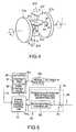
- Fig. 9is a diagrammatic view showing the basic idea of a conventional speed change control.
- a power generating system 100converts the rotative output 101 of an aircraft engine into a rotative driving force 104 of a fixed rotating speed by a continuously variable transmission mechanism 103 including a toroidal continuously variable transmission 102, and drives a generator 105 by the rotative driving force 104 to produce an alternate current of a predetermined frequency.
- the power generating system 100employs a hydraulic cylinder actuator 111 as an actuator for adjusting the tilt angle of a power roller 110 included in the toroidal continuously variable transmission 102.
- the hydraulic cylinder actuator 111shifts the position of the axis of rotation of the power roller 110 (hereinafter referred to as "power roller position”) to adjust the tilt angle of the power roller 110.
- a control systemcontrols the continuously-variable transmission mechanism 103.
- the control systemincludes a subtractor 109 which subtracts a measured rotating speed 107 of the output shaft that provides the rotative driving force 104 of the toroidal continuously variable transmission 102 from a desired rotating speed 106 of the output shaft of the toroidal continuously variable transmission 102 to obtain a rotating speed difference 108, a rotating speed controller 113 which generates a desired power roller position 112 specifying a power roller position for reducing the rotating speed difference 108 to zero, and a tilt angle control loop 114 which controls the tilt angle of the power roller 110 in a feedback control mode to make a measured power roller position 115 coincide with the desired power roller position 112.
- the tilt angle control loop 114includes a position subtractor 117 which subtracts the measured power roller position 115 from the desired power roller position 112 to provide a power roller position difference 116, and a position controller 119 which generates a desired valve opening signal 118 indicating a desired opening of a flow control valve, not shown, for controlling the flow of a working fluid into the hydraulic cylinder actuator 111.
- the tilt angle control loop 114i.e., a local feedback control loop, of the power generating system 100 controls the tilt angle of the power roller 110 on the basis of the measured power roller position 115 to control speed change ratio.
- Fig. 10shows a mechanism 200 proposed in Japanese Pat. No. 2568684 including a local feedback control system.
- the control mechanism 200measures a tilt angle change ⁇ g in the tilt angle of a power roller 201 mechanically by a precession cam, and changes power roller position to control the tilt angle of the power roller 201 in a feedback control mode.
- the control mechanism 200includes a hydraulic cylinder actuator 202 for changing the power roller position, a flow control valve mechanism 203 for regulating the flow of a working fluid into the hydraulic cylinder actuator 202, and a tilt angle change measuring mechanism 204 for measuring the tilt angle change ⁇ g mechanically and adjusting the valve opening of the flow control valve mechanism 203.
- the flow control valve mechanism 203includes a sleeve 206 driven for axial displacement by a speed change motor 205, a spool 208 fitted in the bore of the sleeve 206 and urged by a spring 207 in a direction to increase the valve opening, and a port 209 opened and closed by the spool 208.
- the control mechanism 200provides a speed change signal indicating a desired speed change ratio for the toroidal continuously variable transmission 102 corresponding to an angular position for the output shaft of the speed change motor 205, and adjusts the valve opening of the flow control valve mechanism 203 according to the tilt angle change ⁇ g mechanically measured by the tilt angle change measuring mechanism 204.
- the flow of the working fluid supplied to the hydraulic cylinder actuator 202is adjusted to provide a power roller position signal.
- the position 214 of a piston 213 included in the hydraulic cylinder actuator 202is displaced according to the change of the flow of the working fluid to adjust the power roller position.
- Fig. 11shows another control mechanism 300 proposed in JP-A No. 257686/2000.
- the control mechanism 300employs a position sensor, such as a linear variable differential transformer (abbreviated to "LVDT"), for measuring a tilt angle change ⁇ g in the tilt angle of a power roller 301.
- the control mechanism 300controls the tilt angle of the power roller 301 on the basis of a data provided by the position sensor 302 in a feedback control mode.
- the position sensor.302measures the position of a piston 304 included in a hydraulic cylinder actuator 303 for adjusting the position of the power roller 301 to determine a power roller position.
- the position sensor 302gives measured power roller position data 305 to a position controller 306.
- the position controller 306generates a valve-opening signal 309 indicating a valve opening for a flow control valve mechanism 308 on the basis of the power roller position data 305 and a speed change signal 307.
- the flow of the working fluid supplied to the hydraulic cylinder actuator 303is adjusted according to the valve-opening signal 309 to adjust the power roller position.
- a method of mechanically measuring the tilt angle change in the tilt angle of the power rollerrequires the effect of machining errors in the dimensions of the components of the measuring mechanism, assembly errors in the measuring mechanism, and errors attributable to play and backlash between the component parts on the accuracy of measurement to be limited below a level that will adversely affect the accuracy of measurement.
- a precise speed change ratio controlis necessary, the dimensional accuracies of the component parts of the measuring mechanism must be raised, and the component parts need very difficult machining and assembling work.
- the mechanical measuring mechanismSince the mechanical measuring mechanism is an assembly of many accurate component parts, the measuring mechanism becomes unavoidably large and heavy. Such a measuring mechanism is unsuitable for use on an aircraft and is inevitably costly.
- the performance of the mechanical measuring mechanismis greatly affected by the deterioration of the accuracy of the component parts with time. Increase in play and backlash between the component parts with time and deformation of the component parts deteriorate the accuracy of control and entails the deterioration of the stability and performance of the power generating system.
- the control mechanism 300 proposed in JP-A No. 257686/2000 employing the highly accurate position sensor, such as a LVDT, for measuring the power roller positionis inevitably large and heavy.
- the control mechanism 300is difficult to install when the same is applied to an aircraft power generating system, and such a highly accurate position sensor is expensive and increases the costs of the control mechanism 300 unavoidably.
- the present inventionhas been made in view of the foregoing problems and it is therefore an object of the present invention to provide a speed change control method and a speed change controller capable of maintaining a satisfactory control characteristic for an extended period of use and of enabling a continuously variable transmission mechanism including a traction continuously-variable transmission to be formed in small, lightweight construction and to be manufactured at low costs.
- a speed change control method of controlling a speed change ratio of a continuously variable transmission mechanism including a traction continuously variable transmissioncomprises: estimating a tilt angle of a power roller included in the continuously variable transmission based on an input rotating speed and an output rotating speed of the continuously-variable transmission mechanism; estimating a position of the power roller based on an estimated tilt angle obtained by the tilt angle estimating step and a command signal given to a driving device of adjusting the tilt angle of the power roller; and executing a feedback control operation based on an estimated position of the power roller obtained by the position estimating step.
- the speed change ratio of the continuously variable transmission mechanismis controlled so that the output rotating speed of the continuously variable transmission mechanism coincides with a predetermined rotating speed.
- the position of the power rolleris estimated by an observer constituted using the tilt angle and a model of the driving device.
- the driving deviceincludes a hydraulic cylinder actuator.
- a speed change controllerfor controlling a speed change ratio of a continuously variable transmission mechanism including a traction continuously variable transmission, comprises: a tilt angle estimating unit of estimating a tilt angle of a power roller included in the continuously variable transmission based on an input rotating speed and an output rotating speed of the continuously variable transmission mechanism; and a power roller position estimating unit of estimating a position of the power roller based on an estimated tilt angle estimated by the tilt angle estimating unit and a command signal given to a driving device of adjusting the tilt angle of the power roller, the position of the power roller estimated by the power roller position estimating unit being used to execute a feed back control operation.
- the speed change ratio of the continuously variable transmission mechanismis controlled so that the output rotating speed of the continuously variable transmission mechanism coincides with a predetermined rotating speed.
- the power roller position estimating unitincludes an observer constituted using the tilt angle and a model of the driving device.
- the driving deviceincludes a hydraulic cylinder actuator.
- Fig. 1shows a power generating system A including a speed change controller 50 for carrying out a speed change control method in a preferred embodiment according to the present invention.
- the power generating system Aproduces an alternate current of a predetermined frequency by using the rotative output of, for example, the main engine of an aircraft.
- the power generating system Aincludes, as principal components, a generator 10, a continuously variable transmission mechanism 20 which converts an input rotating speed of its input member, i.e., the rotating speed N 1 of the output member of an engine E (hereinafter referred to as "engine speed N 1 "), into a predetermined output rotating speed, i.e., the rotating speed N 2 of the input member of the generator 10 (hereinafter referred to as "generator input speed N 2 ”) and transmits the rotative power of the engine E to the generator 10, an engine speed sensor 30 for measuring the engine speed N 1 , generator input speed sensor 40 for measuring the generator input speed N 2 , and a speed change controller 50 for controlling the speed change ratio of the continuously variable transmission mechanism 20 on the basis of signals provided by the engine speed sensor 30 and the generator input speed sensor 40 so that the generator input speed N 2 coincides with a predetermined rotating speed.
- engine speed N 1the rotating speed of the output member of an engine E
- generator input speed N 2the rotating speed N 2
- a speed change controller 50
- the generator 10generates power necessary for driving the electric equipment of the aircraft including a lighting system, an air conditioning system and an anti-icing system.
- the generator 10is driven for rotation at a predetermined operating speed of, for example, 24,000 rpm to generate an alternate current of a predetermined frequency of, for example, 400 Hz.
- the generator 10is of known construction and hence further description thereof will be omitted.
- the continuously variable transmission mechanism 20includes a traction-drive toroidal continuously variable transmission (hereinafter referred to simply as "traction continuously variable transmission") 21, and a planetary gear 22.
- the continuously variable transmission mechanism 20converts the engine speed N 1 in a predetermined range of, for example, 4,500 to 9,200 rpm into the predetermined operating speed to drive the generator 10 for operation at the predetermined operating speed.
- the continuously variable transmission mechanism 20is a power-split transmission mechanism which does not transmits all the rotative driving force applied to its input shaft 23 through the traction continuously variable transmission 21 to the generator 10, but splits the input power and distributes power to the generator 10 and the planetary gear 22.
- a gear 23ais mounted on the input shaft 23 of the continuously variable transmission mechanism 20, the traction continuously variable transmission 21 has a gear 25a mounted on its input shaft 25 and engaged with the gear 23a.
- the input shaft 25 of the traction continuously variable transmission 21is interlocked with the input shaft 23 of the continuously variable transmission mechanism 20.
- Gears 24a and 24bare mounted on the opposite ends of an idle shaft 24, i.e., a power splitting shaft 24, respectively.
- the gear 24ais engaged with the gear 23a
- the gear 24bis engaged with a ring gear 22b included in the planetary gear 22.
- rotative driving force applied to the input shaft 23 of the continuously variable transmission mechanism 20is distributed to the traction continuously variable transmission 21 and the planetary gear 22.
- the traction continuously variable transmission 21is of a half-toroidal type and has an input disk 21a mounted on the input shaft 25 for rotation together with the input shaft 25, an output disk 21b mounted on the output shaft 26 of the traction continuously variable transmission 21 for rotation together with the output shaft 26, a plurality of power rollers 21c held between the input disk 21a and the output disk 21b, and a thrust mechanism 21d for applying pressure to the power rollers 21c.
- the input disk 21a and the output disk 21bhave friction surfaces 21e and 21f, respectively.
- the friction surfaces 21e and 21fhave the shape of quadrants symmetrical with respect to the rotation axis I thereof in a plane including the rotation axis I.
- Each power roller 21cis held between the input disk 21a and the output disk 21b by a thrust bearing 21g and support members, i.e., known trunnions, not shown, for rotation about its center axis 21h and for tilting in a plane including the center axes 21h and the rotation axis I.
- a thrust bearing 21g and support membersi.e., known trunnions, not shown
- the input disk 21a, the output disk 21b and the power rollers 21ci.e., the rolling elements, are pressed together by high pressure. Power is transmitted from the input disk 21a through the power rollers 21c to the output disk 21b by the shearing resistance of a film of a high-viscosity oil formed between the contact surfaces of those rolling elements.
- the speed change ratiois changed in a predetermined range of, for example 0.5 to 2.0 by changing the tilt angle ⁇ of each power roller 21c, i.e., the angle between a segment OQ and a straight line R perpendicular to the center axis I of the disks 21a and 21b and passing a point O, where Q is a point of contact of the power roller 21c and the input disk 21a, and O is the center of a circle circumscribing the friction surface 21e of the power roller 21c.
- the tilting of the power rollers 21cis limited by mechanical stoppers to permit the tilt angle ⁇ to change only in the predetermined range.
- R iis input working radius, i.e., the distance between the center axis I and the point of contact between the input disk 21a and the power roller 21c
- R ois output working radius, i.e., the distance between the center axis I and the point of contact between the output disk 21b and the power roller 31c
- N iis the rotating speed of the input shaft and the input disk 21a
- N ois the rotating speed of the output shaft and the output disk 21b
- R CVTis the speed change ratio.
- the working radii R i and R ocan be continuously changed by controlling the tilt angle ⁇ of each power roller 21c and, consequently, the speed change ratio N o /N i can be continuously changed. Since the speed change ratio R CVT is dependent on the ratio, R i /R o , the speed change ratio can be continuously changed by changing the tilt angle ⁇ of the power rollers 21c.
- the planetary gear 22includes the ring gear 22b interlocked, as mentioned above, with the input shaft 23 of the continuously variable transmission mechanism 20 through the idle shaft (power splitting shaft) 24, a sun gear 22a fixedly mounted on or formed integrally with the output shaft 26 of the traction continuously variable transmission 21, a plurality of planet pinions 22c interposed between the sun gear 22a and the ring gear 22b, and a carrier 22d supporting the planet pinions 22c for rotation and capable of rotating about the axis of the sun gear 22a as the planet pinions 22c revolve about the axis of the sun gear 22a.
- the planetary gear 22Since the planet pinions 22c are supported for rotation on the carrier 22d, and the sun gear 22a and the ring gear 22b are rotatable, the planetary gear 22 has two degrees of freedom of motion, and the planetary gear 22 is interlocked with the idle shaft (power splitting shaft) 24.
- the rotative driving force for driving the generator 10can be distributed to the traction continuously variable transmission 21 and the power splitting shaft 24.
- the rotating speed of the carrier 22dcan be fixed at, for example, 6255 rpm by varying the rotating speed of the sun gear 22a by the traction continuously variable transmission 21 according to the variation of the rotating speed of the input shaft 23 equal to the engine speed N 1 .
- the rotating speed of the carrier 22dis increased by a gear train 27 to drive the generator 10 for operation at a fixed operating speed of, for example, 24,000 rpm.
- the rotative driving force for driving the generator 10is transmitted through both the traction continuously variable transmission 21 and the planetary gear 22 instead of transmitting the same only through the traction continuously variable transmission 21 to the generator 10. Consequently, the life of the traction continuously variable transmission 21 can be extended, and the traction continuously-variable transmission 21 can be formed in small, lightweight construction.
- the continuously variable transmissionhas a comparatively low power transmission capacity.
- the upper limit of power that can be transmitted by the continuously variable transmission mechanism 20can be readily raised by distributing the rotative driving force of the engine E to the power splitting shaft 24 and the traction continuously variable transmission 21. Since the planetary gear 22 operates at an efficiency not lower than 99%, the power transmission efficiency of the continuously variable transmission mechanism 20 is as high as about 95%.
- the engine seed sensor 30 and the generator input speed sensor 40will be described.
- Each of the engine speed sensor 30 and the generator input speed sensor 40is, for example, a combination of a pulse generator, not shown, and a pulse counter, not shown.
- the engine speed N 1 and the generator input speed N 2are determined by counting pulses generated by the pulse generators by the pulse counters, respectively.
- the engine speed sensor 30 and the generator input speed sensor 40provide signals indicating a measured engine speed N 1 and a measured generator input speed N 2 , respectively.
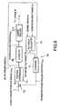
- the speed change controller 50has a unit 60 of generating a signal specifying a power roller position and a power roller position control unit 70.
- the unit 60has a subtractor 61 which subtracts a measured generator input speed from a specified generator input speed y, i.e., a desired value of the generator input speed N 2 , and provides a rotating speed difference signal indicating the rotating speed difference e, and a rotating speed controller 62 which generates a power roller position specifying signal x PRc indicating a power roller position that reduces the rotating speed difference signal to zero.
- a subtractor 61which subtracts a measured generator input speed from a specified generator input speed y, i.e., a desired value of the generator input speed N 2 , and provides a rotating speed difference signal indicating the rotating speed difference e
- a rotating speed controller 62which generates a power roller position specifying signal x PRc indicating a power roller position that reduces the rotating speed difference signal to zero.
- the power roller position control unit 70generates an actuator operating signal i, i.e., a control signal for controlling the actuator 80, on the basis of the power roller position specifying signal x PRc received from the rotating speed controller 62, the measured engine speed N 1 and the measured generator input speed N 2 to control the actuator 80.
- an actuator operating signal ii.e., a control signal for controlling the actuator 80
- the position of the piston rod 81 of the actuator 80i.e., a hydraulic cylinder actuator, is controllable by adjusting the opening of a flow control valve 82 for controlling the flow of the working fluid supplied to the cylinder of the actuator 80.
- the actuator operating signal ispecifies an opening of the flow control valve 82 such that the an estimated power roller position Y x PR calculated by a method which will be described later coincides with a position indicated by the power roller position signal x PRc .
- the power roller position control unit 70has an observer 71 which carries out a predetermined power roller position estimating process to estimate a power roller position and provides a signal indicating the estimated power roller position Y x PR , a subtractor 72 which subtracts the estimated power roller position Y x PR from the power position specifying signal x PRc to obtain a position difference e p , and provides a signal indicating the position difference e p , a position controller 73 which provides a valve opening specifying signal i to reduce the position difference e p to zero, and a tilt angle calculator 74 which carries out a predetermined tilt angle estimating process to estimate the tilt angle of the power rollers 21c and provides an estimated tilt angle Y ⁇ .
- the symbol Y x PRindicates an estimated value of x PR
- a symbol Y ⁇indicates an estimated value of ⁇ .
- Space state matrices A and Bare divided as represented by Expressions (5), (6) and (7).
- Symbols A and B in Expressions (5), (6) and (7)are expressed by Expressions (8) and (9).
- a design parameter Lis adjusted so that a pole of the observer, i.e., the characteristic value of estimated matrix Y A represented by Expression (10) is stabilized.
- Y AA 22 - LA 12
- Matrices Y B, G, Y C and Y Dcan be represented by Expressions (11), (12), (13) and (14) by using a matrix L.
- Y B- LB 1 + B 2
- GY AL + A 21 - LA 21
- the observer 71can be designed as a minimum dimension observer represented by Expressions (15) and (16) from the models of tilt angle ⁇ and power roller position X PR .
- the tilt angle calculator 74calculates the estimated tilt angle Y ⁇ on the basis of the engine speed N 1 and the generator input speed N 2 , the observer 71 estimates the power roller position on the basis of the estimated tilt angle Y ⁇ and the valve opening signal i, i.e., an input control signal.
- the speed change controlleris capable of accurate speed change ratio control without requiring any position measuring mechanism, such as a position sensor.
- the power generating systemcan be constructed in small, lightweight construction, work for the maintenance of the power generating system is facilitated, and the power generating system can be manufactured at low costs.
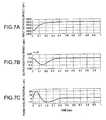
- Figs. 7A to 7C and Figs. 8A to 8Care graphs comparatively showing the respective characteristics of the speed change controller employing the observer 71, and a speed change controller employing a position sensor as a related art.
- Figs. 7A, 7B and 7Care graphs showing the variation of the input rotating speed of the continuously variable transmission mechanism 20, i.e., engine speed N 1 , with time, the variation of the output rotating speed of the continuously variable transmission, i.e., the generator input speed N 2 , with time and the variation of power roller position with time, respectively, when the continuously variable transmission mechanism 20 is controlled by a speed change controller using the estimated power roller position Y x PR determined by the observer 71.
- the engine speed N 1is measured on the vertical axis and time is measured on the horizontal axis in Fig. 7A
- the generator input speed N 2is measured on the vertical axis and time is measured on the horizontal axis in Fig. 7B
- the measured power roller positionis measured on the vertical axis and time is measured on the horizontal axis in Fig. 7C.
- Figs. 8A, 8B and 8Care graphs showing the variation of the input rotating speed of the continuously variable transmission mechanism 20, i.e., engine speed N 1 , with time, the variation of the output rotating speed of the continuously variable transmission, i.e., the generator input speed N 2 , with time and the variation of power roller position with time, respectively, when the continuously variable transmission mechanism 20 is controlled by a speed change controller using the measured power roller position measured by a position sensor as a related art.
- the engine speed N 1is measured on the vertical axis and time is measured on the horizontal axis in Fig. 8A
- the generator input speed N 2is measured on the vertical axis and time is measured on the horizontal axis in Fig. 8B
- the measured power roller positionis measured on the vertical axis and time is measured on the horizontal axis in Fig. 8C.
- the observer 71may be an all-dimension observer or a nonlinear observer (Japanese. Pat. App. No. 075566/2000) instead of the minimum-dimension observer.
- the use of a minimum-dimension observerreduces the number of parameters necessary for adjustment and facilitates adjustment.
- the speed change controller of the present inventionis applicable not only to the half-toroidal continuously variable transmission, but also to any continuously variable transmissions that are expected to be satisfactorily controlled by employing an observer.
- the speed change controllerestimates the tilt angle of the power rollers on the basis of the input and the output rotating speed of the continuously-variable transmission mechanism, estimates the power roller position on the basis of the estimated tilt angle and the signal given to the driving device for driving the power rollers, and controls the tilt angle of the power rollers on the basis of the estimated power roller position in a feedback control mode. Therefore, accurate speed change ratio control can be achieved without using any position sensor for measuring the power roller position in a high accuracy substantially the same as that in which a speed change controller using a position sensor can achieve speed change ratio control.
- the system including the continuously variable transmission mechanism and the speed change controllercan be formed in small, lightweight construction and can be manufactured at low costs.
Landscapes
- Engineering & Computer Science (AREA)
- General Engineering & Computer Science (AREA)
- Mechanical Engineering (AREA)
- Control Of Transmission Device (AREA)
- Friction Gearing (AREA)
Abstract
Description
estimating a position of the power roller based on anestimated tilt angle obtained by the tilt angle estimatingstep and a command signal given to a driving device ofadjusting the tilt angle of the power roller; and executinga feedback control operation based on an estimated positionof the power roller obtained by the position estimating step.


Claims (12)
- A speed change control method of controlling a speedchange ratio of a continuously variable transmissionmechanism including a traction continuously variabletransmission, comprising:estimating a tilt angle of a power roller included inthe continuously variable transmission based on an inputrotating speed and an output rotating speed of thecontinuously-variable transmission mechanism;estimating a position of the power roller based on anestimated tilt angle obtained by the tilt angle estimatingstep and a command signal given to a driving device ofadjusting the tilt angle of the power roller; andexecuting a feedback control operation based on anestimated position of the power roller obtained by theposition estimating step.
- The speed change control method according to claim1, wherein the speed change ratio of the continuously variabletransmission mechanism is controlled so that the outputrotating speed of the continuously variable transmissionmechanism coincides with a predetermined rotating speed.
- The speed change control method according to claim1, wherein the position of the power roller is estimated byan observer constituted using the tilt angle and a model ofthe driving device.
- The speed change control method according to claim2, wherein the position of the power roller is estimated byan observer constituted using the tilt angle and a model ofthe driving device.
- The speed change control method according to claim3, wherein the driving device includes a hydraulic cylinderactuator.
- The speed change control method according to claim4, wherein the driving device includes a hydraulic cylinderactuator.
- A speed change controller for controlling a speedchange ratio of a continuously variable transmission mechanism including a traction continuously variabletransmission, comprising:a tilt angle estimating unit of estimating a tilt angleof a power roller included in the continuously variabletransmission based on an input rotating speed and an outputrotating speed of the continuously variable transmissionmechanism; anda power roller position estimating unit of estimatinga position of the power roller based on an estimated tiltangle estimated by the tilt angle estimating unit and acommand signal given to a driving device of adjusting thetilt angle of the power roller, the position of the powerroller estimated by the power roller position estimating unitbeing used to execute a feed back control operation.
- The speed change controller according to claim 7,wherein the speed change ratio of the continuously variabletransmission mechanism is controlled so that the outputrotating speed of the continuously variable transmissionmechanism coincides with a predetermined rotating speed.
- The speed change controller according to claim 7,wherein the power roller position estimating unit includesan observer constituted using the tilt angle and a model ofthe driving device.
- The speed change controller according to claim 8,wherein the power roller position estimating unit includesan observer constituted using the tilt angle and a model ofthe driving device.
- The speed change controller according to claim 9,wherein the driving device includes a hydraulic cylinderactuator.
- The speed change controller according to claim 10,wherein the driving device includes a hydraulic cylinderactuator.
Applications Claiming Priority (2)
| Application Number | Priority Date | Filing Date | Title |
|---|---|---|---|
| JP2001121716 | 2001-04-19 | ||
| JP2001121716AJP3914999B2 (en) | 2001-04-19 | 2001-04-19 | Shift control method and shift control apparatus |
Publications (3)
| Publication Number | Publication Date |
|---|---|
| EP1251294A2true EP1251294A2 (en) | 2002-10-23 |
| EP1251294A3 EP1251294A3 (en) | 2006-03-29 |
| EP1251294B1 EP1251294B1 (en) | 2011-10-05 |
Family
ID=18971527
Family Applications (1)
| Application Number | Title | Priority Date | Filing Date |
|---|---|---|---|
| EP02008730AExpired - LifetimeEP1251294B1 (en) | 2001-04-19 | 2002-04-18 | Speed change control method and speed change controller |
Country Status (4)
| Country | Link |
|---|---|
| US (1) | US6871128B2 (en) |
| EP (1) | EP1251294B1 (en) |
| JP (1) | JP3914999B2 (en) |
| AT (1) | ATE527477T1 (en) |
Cited By (35)
| Publication number | Priority date | Publication date | Assignee | Title |
|---|---|---|---|---|
| US8169100B2 (en) | 2008-01-30 | 2012-05-01 | Pratt & Whitney Canada Corp. | Torque transmission for an aircraft engine |
| US8519555B2 (en) | 2010-11-29 | 2013-08-27 | Pratt & Whitney Canada Corp. | Combination low spool generator and ram air turbine generator |
| WO2015094275A1 (en) | 2013-12-19 | 2015-06-25 | Sikorsky Aircraft Corporation | De-rotation system for a shaft fairing |
| US20150226323A1 (en)* | 2006-06-26 | 2015-08-13 | Fallbrook Intellectual Property Company Llc | Continuously variable transmission |
| US9676391B2 (en) | 2007-02-01 | 2017-06-13 | Fallbrook Intellectual Property Company Llc | Systems and methods for control of transmission and/or prime mover |
| US9677650B2 (en) | 2013-04-19 | 2017-06-13 | Fallbrook Intellectual Property Company Llc | Continuously variable transmission |
| US9683638B2 (en) | 2005-12-30 | 2017-06-20 | Fallbrook Intellectual Property Company Llc | Continuously variable gear transmission |
| US9683640B2 (en) | 2008-06-06 | 2017-06-20 | Fallbrook Intellectual Property Company Llc | Infinitely variable transmissions, continuously variable transmissions, methods, assemblies, subassemblies, and components therefor |
| US9709138B2 (en) | 2005-11-22 | 2017-07-18 | Fallbrook Intellectual Property Company Llc | Continuously variable transmission |
| US9739375B2 (en) | 2007-12-21 | 2017-08-22 | Fallbrook Intellectual Property Company Llc | Automatic transmissions and methods therefor |
| US9850993B2 (en) | 2008-02-29 | 2017-12-26 | Fallbrook Intellectual Property Company Llc | Continuously and/or infinitely variable transmissions and methods therefor |
| US9869388B2 (en) | 2007-07-05 | 2018-01-16 | Fallbrook Intellectual Property Company Llc | Continuously variable transmission |
| US9878717B2 (en) | 2008-08-05 | 2018-01-30 | Fallbrook Intellectual Property Company Llc | Systems and methods for control of transmission and/or prime mover |
| US9903450B2 (en) | 2008-08-26 | 2018-02-27 | Fallbrook Intellectual Property Company Llc | Continuously variable transmission |
| US9920823B2 (en) | 2009-04-16 | 2018-03-20 | Fallbrook Intellectual Property Company Llc | Continuously variable transmission |
| US9945456B2 (en) | 2007-06-11 | 2018-04-17 | Fallbrook Intellectual Property Company Llc | Continuously variable transmission |
| US9950608B2 (en) | 2005-10-28 | 2018-04-24 | Fallbrook Intellectual Property Company Llc | Electromotive drives |
| US10036453B2 (en) | 2004-10-05 | 2018-07-31 | Fallbrook Intellectual Property Company Llc | Continuously variable transmission |
| US10047861B2 (en) | 2016-01-15 | 2018-08-14 | Fallbrook Intellectual Property Company Llc | Systems and methods for controlling rollback in continuously variable transmissions |
| US10056811B2 (en) | 2007-04-24 | 2018-08-21 | Fallbrook Intellectual Property Company Llc | Electric traction drives |
| US10066713B2 (en) | 2008-06-23 | 2018-09-04 | Fallbrook Intellectual Property Company Llc | Continuously variable transmission |
| US10066712B2 (en) | 2010-03-03 | 2018-09-04 | Fallbrook Intellectual Property Company Llc | Infinitely variable transmissions, continuously variable transmissions, methods, assemblies, subassemblies, and components therefor |
| US10094453B2 (en) | 2007-02-16 | 2018-10-09 | Fallbrook Intellectual Property Company Llc | Infinitely variable transmissions, continuously variable transmissions, methods, assemblies, subassemblies, and components therefor |
| US10100927B2 (en) | 2007-11-16 | 2018-10-16 | Fallbrook Intellectual Property Company Llc | Controller for variable transmission |
| US10197147B2 (en) | 2010-11-10 | 2019-02-05 | Fallbrook Intellectual Property Company Llc | Continuously variable transmission |
| US10208840B2 (en) | 2005-12-09 | 2019-02-19 | Fallbrook Intellectual Property Company Llc | Continuously variable transmission |
| US10253880B2 (en) | 2008-10-14 | 2019-04-09 | Fallbrook Intellectual Property Company Llc | Continuously variable transmission |
| US10260607B2 (en) | 2007-02-12 | 2019-04-16 | Fallbrook Intellectual Property Company Llc | Continuously variable transmissions and methods therefor |
| US10400872B2 (en) | 2015-03-31 | 2019-09-03 | Fallbrook Intellectual Property Company Llc | Balanced split sun assemblies with integrated differential mechanisms, and variators and drive trains including balanced split sun assemblies |
| US10428939B2 (en) | 2003-02-28 | 2019-10-01 | Fallbrook Intellectual Property Company Llc | Continuously variable transmission |
| US10428915B2 (en) | 2012-01-23 | 2019-10-01 | Fallbrook Intellectual Property Company Llc | Infinitely variable transmissions, continuously variable transmissions, methods, assemblies, subassemblies, and components therefor |
| US10458526B2 (en) | 2016-03-18 | 2019-10-29 | Fallbrook Intellectual Property Company Llc | Continuously variable transmissions, systems and methods |
| US11174922B2 (en) | 2019-02-26 | 2021-11-16 | Fallbrook Intellectual Property Company Llc | Reversible variable drives and systems and methods for control in forward and reverse directions |
| US11215268B2 (en) | 2018-11-06 | 2022-01-04 | Fallbrook Intellectual Property Company Llc | Continuously variable transmissions, synchronous shifting, twin countershafts and methods for control of same |
| US11667351B2 (en) | 2016-05-11 | 2023-06-06 | Fallbrook Intellectual Property Company Llc | Systems and methods for automatic configuration and automatic calibration of continuously variable transmissions and bicycles having continuously variable transmission |
Families Citing this family (19)
| Publication number | Priority date | Publication date | Assignee | Title |
|---|---|---|---|---|
| US7552781B2 (en) | 2004-10-20 | 2009-06-30 | Black & Decker Inc. | Power tool anti-kickback system with rotational rate sensor |
| US20070265761A1 (en)* | 2006-05-11 | 2007-11-15 | Dooley Kevin A | Electric power generation system and method |
| US8118706B2 (en)* | 2008-06-30 | 2012-02-21 | Caterpillar Inc. | Machine having a multiple-ratio transmission |
| CA2727789A1 (en)* | 2009-12-23 | 2011-06-23 | Hubert Roberge | Electronically controlled continuously variable transmission with torque limiting system and method thereof |
| US9266178B2 (en) | 2010-01-07 | 2016-02-23 | Black & Decker Inc. | Power tool having rotary input control |
| US9475180B2 (en) | 2010-01-07 | 2016-10-25 | Black & Decker Inc. | Power tool having rotary input control |
| CN102753782B (en)* | 2010-01-07 | 2015-09-30 | 布莱克和戴克公司 | There is the electric screw driver rotating input control |
| US8418778B2 (en) | 2010-01-07 | 2013-04-16 | Black & Decker Inc. | Power screwdriver having rotary input control |
| EP2631035B1 (en) | 2012-02-24 | 2019-10-16 | Black & Decker Inc. | Power tool |
| US20130232941A1 (en)* | 2012-03-07 | 2013-09-12 | Ge Aviation Systems Llc | Apparatus for extracting input power from the low pressure spool of a turbine engine |
| US20130296091A1 (en)* | 2012-05-02 | 2013-11-07 | Hamilton Sundstrand Corporation | Variable speed drive for aircarft applications |
| WO2015055441A1 (en)* | 2013-10-15 | 2015-04-23 | Universiteit Gent | Wave energy convertor |
| CN104881580B (en)* | 2015-05-27 | 2017-08-29 | 中国人民解放军国防科学技术大学 | A kind of in-orbit health status index extraction of satellite drive mechanism and life-span prediction method |
| JP6706666B2 (en)* | 2016-03-07 | 2020-06-10 | 川崎重工業株式会社 | Synchronous closing control method and synchronous closing control device |
| EP3951214B1 (en) | 2016-03-07 | 2023-05-03 | Kawasaki Jukogyo Kabushiki Kaisha | Controller of toroidal continuously variable transmission |
| WO2017154037A1 (en)* | 2016-03-08 | 2017-09-14 | 川崎重工業株式会社 | Shift control device |
| US10754362B1 (en)* | 2019-02-20 | 2020-08-25 | Fisher Controls International, Llc | Adjustment of loop-powered pneumatic process control device interfaces |
| US11003151B2 (en) | 2019-02-20 | 2021-05-11 | Fisher Controls International Llc | Loop-powered control of pneumatic process control devices |
| RU2712714C1 (en)* | 2019-06-25 | 2020-01-30 | Олег Вениаминович Биянов | Planetary gear with controlled gear ratio |
Citations (2)
| Publication number | Priority date | Publication date | Assignee | Title |
|---|---|---|---|---|
| JP2000075566A (en) | 1998-08-31 | 2000-03-14 | Fuji Xerox Co Ltd | Image forming device |
| JP2000257686A (en) | 1999-03-08 | 2000-09-19 | Nsk Ltd | Toroidal type continuously variable transmission |
Family Cites Families (13)
| Publication number | Priority date | Publication date | Assignee | Title |
|---|---|---|---|---|
| US4382188A (en)* | 1981-02-17 | 1983-05-03 | Lockheed Corporation | Dual-range drive configurations for synchronous and induction generators |
| JPS6131755A (en)* | 1984-07-20 | 1986-02-14 | Nippon Seiko Kk | Apparatus for coltrolling speed change ratio of toroidal type non-stage transmission |
| JP2568684B2 (en) | 1989-04-25 | 1997-01-08 | 日産自動車株式会社 | Friction wheel type continuously variable transmission |
| EP1059473B1 (en)* | 1995-02-28 | 2002-09-11 | Isuzu Motors Limited | Toroidal continuous variable transmission |
| JP3257331B2 (en) | 1995-03-29 | 2002-02-18 | 日産自動車株式会社 | Transmission control device for toroidal type continuously variable transmission |
| JP3404973B2 (en)* | 1995-03-29 | 2003-05-12 | 日産自動車株式会社 | Transmission control device for toroidal type continuously variable transmission |
| JP3760545B2 (en)* | 1996-03-29 | 2006-03-29 | マツダ株式会社 | Control device for automatic transmission |
| JP3911749B2 (en)* | 1996-03-29 | 2007-05-09 | マツダ株式会社 | Control device for automatic transmission |
| JPH11223257A (en)* | 1998-02-05 | 1999-08-17 | Nissan Motor Co Ltd | Torque transmission force control device for infinitely variable transmission |
| JPH11257479A (en)* | 1998-03-10 | 1999-09-21 | Honda Motor Co Ltd | Control device for toroidal type continuously variable transmission |
| EP1054193A1 (en)* | 1999-05-21 | 2000-11-22 | Advanced Technology Institute of Commuter-Helicopter, Ltd. | Constant speed traction drive apparatus for aircraft generator |
| JP3436722B2 (en) | 2000-03-17 | 2003-08-18 | 川崎重工業株式会社 | Control device |
| JP2002181185A (en)* | 2000-12-14 | 2002-06-26 | Honda Motor Co Ltd | Clutch control device for continuously variable transmission for vehicle |
- 2001
- 2001-04-19JPJP2001121716Apatent/JP3914999B2/ennot_activeExpired - Fee Related
- 2002
- 2002-04-15USUS10/121,690patent/US6871128B2/ennot_activeExpired - Lifetime
- 2002-04-18ATAT02008730Tpatent/ATE527477T1/ennot_activeIP Right Cessation
- 2002-04-18EPEP02008730Apatent/EP1251294B1/ennot_activeExpired - Lifetime
Patent Citations (2)
| Publication number | Priority date | Publication date | Assignee | Title |
|---|---|---|---|---|
| JP2000075566A (en) | 1998-08-31 | 2000-03-14 | Fuji Xerox Co Ltd | Image forming device |
| JP2000257686A (en) | 1999-03-08 | 2000-09-19 | Nsk Ltd | Toroidal type continuously variable transmission |
Cited By (56)
| Publication number | Priority date | Publication date | Assignee | Title |
|---|---|---|---|---|
| US10428939B2 (en) | 2003-02-28 | 2019-10-01 | Fallbrook Intellectual Property Company Llc | Continuously variable transmission |
| US10036453B2 (en) | 2004-10-05 | 2018-07-31 | Fallbrook Intellectual Property Company Llc | Continuously variable transmission |
| US9950608B2 (en) | 2005-10-28 | 2018-04-24 | Fallbrook Intellectual Property Company Llc | Electromotive drives |
| US9709138B2 (en) | 2005-11-22 | 2017-07-18 | Fallbrook Intellectual Property Company Llc | Continuously variable transmission |
| US10711869B2 (en) | 2005-11-22 | 2020-07-14 | Fallbrook Intellectual Property Company Llc | Continuously variable transmission |
| US11454303B2 (en) | 2005-12-09 | 2022-09-27 | Fallbrook Intellectual Property Company Llc | Continuously variable transmission |
| US10208840B2 (en) | 2005-12-09 | 2019-02-19 | Fallbrook Intellectual Property Company Llc | Continuously variable transmission |
| US11598397B2 (en) | 2005-12-30 | 2023-03-07 | Fallbrook Intellectual Property Company Llc | Continuously variable gear transmission |
| US9683638B2 (en) | 2005-12-30 | 2017-06-20 | Fallbrook Intellectual Property Company Llc | Continuously variable gear transmission |
| US20150226323A1 (en)* | 2006-06-26 | 2015-08-13 | Fallbrook Intellectual Property Company Llc | Continuously variable transmission |
| US9726282B2 (en)* | 2006-06-26 | 2017-08-08 | Fallbrook Intellectual Property Company Llc | Continuously variable transmission |
| US10703372B2 (en) | 2007-02-01 | 2020-07-07 | Fallbrook Intellectual Property Company Llc | Systems and methods for control of transmission and/or prime mover |
| US9878719B2 (en) | 2007-02-01 | 2018-01-30 | Fallbrook Intellectual Property Company Llc | Systems and methods for control of transmission and/or prime mover |
| US9676391B2 (en) | 2007-02-01 | 2017-06-13 | Fallbrook Intellectual Property Company Llc | Systems and methods for control of transmission and/or prime mover |
| US10260607B2 (en) | 2007-02-12 | 2019-04-16 | Fallbrook Intellectual Property Company Llc | Continuously variable transmissions and methods therefor |
| US10094453B2 (en) | 2007-02-16 | 2018-10-09 | Fallbrook Intellectual Property Company Llc | Infinitely variable transmissions, continuously variable transmissions, methods, assemblies, subassemblies, and components therefor |
| US10056811B2 (en) | 2007-04-24 | 2018-08-21 | Fallbrook Intellectual Property Company Llc | Electric traction drives |
| US9945456B2 (en) | 2007-06-11 | 2018-04-17 | Fallbrook Intellectual Property Company Llc | Continuously variable transmission |
| US9869388B2 (en) | 2007-07-05 | 2018-01-16 | Fallbrook Intellectual Property Company Llc | Continuously variable transmission |
| US10260629B2 (en) | 2007-07-05 | 2019-04-16 | Fallbrook Intellectual Property Company Llc | Continuously variable transmission |
| US10100927B2 (en) | 2007-11-16 | 2018-10-16 | Fallbrook Intellectual Property Company Llc | Controller for variable transmission |
| US11125329B2 (en) | 2007-11-16 | 2021-09-21 | Fallbrook Intellectual Property Company Llc | Controller for variable transmission |
| US10704687B2 (en) | 2007-12-21 | 2020-07-07 | Fallbrook Intellectual Property Company Llc | Automatic transmissions and methods therefor |
| US9739375B2 (en) | 2007-12-21 | 2017-08-22 | Fallbrook Intellectual Property Company Llc | Automatic transmissions and methods therefor |
| US8169100B2 (en) | 2008-01-30 | 2012-05-01 | Pratt & Whitney Canada Corp. | Torque transmission for an aircraft engine |
| US9850993B2 (en) | 2008-02-29 | 2017-12-26 | Fallbrook Intellectual Property Company Llc | Continuously and/or infinitely variable transmissions and methods therefor |
| US9683640B2 (en) | 2008-06-06 | 2017-06-20 | Fallbrook Intellectual Property Company Llc | Infinitely variable transmissions, continuously variable transmissions, methods, assemblies, subassemblies, and components therefor |
| US10634224B2 (en) | 2008-06-06 | 2020-04-28 | Fallbrook Intellectual Property Company Llc | Infinitely variable transmissions, continuously variable transmissions, methods, assemblies, subassemblies, and components therefor |
| US10066713B2 (en) | 2008-06-23 | 2018-09-04 | Fallbrook Intellectual Property Company Llc | Continuously variable transmission |
| US9878717B2 (en) | 2008-08-05 | 2018-01-30 | Fallbrook Intellectual Property Company Llc | Systems and methods for control of transmission and/or prime mover |
| US10704657B2 (en) | 2008-08-26 | 2020-07-07 | Fallbrook Intellectual Property Company Llc | Continuously variable transmission |
| US9903450B2 (en) | 2008-08-26 | 2018-02-27 | Fallbrook Intellectual Property Company Llc | Continuously variable transmission |
| US10253880B2 (en) | 2008-10-14 | 2019-04-09 | Fallbrook Intellectual Property Company Llc | Continuously variable transmission |
| US10746270B2 (en) | 2009-04-16 | 2020-08-18 | Fallbrook Intellectual Property Company Llc | Continuously variable transmission |
| US9920823B2 (en) | 2009-04-16 | 2018-03-20 | Fallbrook Intellectual Property Company Llc | Continuously variable transmission |
| US10066712B2 (en) | 2010-03-03 | 2018-09-04 | Fallbrook Intellectual Property Company Llc | Infinitely variable transmissions, continuously variable transmissions, methods, assemblies, subassemblies, and components therefor |
| US10197147B2 (en) | 2010-11-10 | 2019-02-05 | Fallbrook Intellectual Property Company Llc | Continuously variable transmission |
| US8519555B2 (en) | 2010-11-29 | 2013-08-27 | Pratt & Whitney Canada Corp. | Combination low spool generator and ram air turbine generator |
| US10428915B2 (en) | 2012-01-23 | 2019-10-01 | Fallbrook Intellectual Property Company Llc | Infinitely variable transmissions, continuously variable transmissions, methods, assemblies, subassemblies, and components therefor |
| US10323732B2 (en) | 2013-04-19 | 2019-06-18 | Fallbrook Intellectual Property Company Llc | Continuously variable transmission |
| US9677650B2 (en) | 2013-04-19 | 2017-06-13 | Fallbrook Intellectual Property Company Llc | Continuously variable transmission |
| WO2015094275A1 (en) | 2013-12-19 | 2015-06-25 | Sikorsky Aircraft Corporation | De-rotation system for a shaft fairing |
| EP3083397A4 (en)* | 2013-12-19 | 2017-08-02 | Sikorsky Aircraft Corporation | De-rotation system for a shaft fairing |
| US10400872B2 (en) | 2015-03-31 | 2019-09-03 | Fallbrook Intellectual Property Company Llc | Balanced split sun assemblies with integrated differential mechanisms, and variators and drive trains including balanced split sun assemblies |
| US10920882B2 (en) | 2016-01-15 | 2021-02-16 | Fallbrook Intellectual Property Company Llc | Systems and methods for controlling rollback in continuously variable transmissions |
| US10047861B2 (en) | 2016-01-15 | 2018-08-14 | Fallbrook Intellectual Property Company Llc | Systems and methods for controlling rollback in continuously variable transmissions |
| US11306818B2 (en) | 2016-01-15 | 2022-04-19 | Fallbrook Intellectual Property Company Llc | Systems and methods for controlling rollback in continuously variable transmissions |
| US10458526B2 (en) | 2016-03-18 | 2019-10-29 | Fallbrook Intellectual Property Company Llc | Continuously variable transmissions, systems and methods |
| US12145690B2 (en) | 2016-05-11 | 2024-11-19 | Enviolo B.V. | Systems and methods for automatic configuration and automatic calibration of continuously variable transmissions and bicycles having continuously variable transmissions |
| US11667351B2 (en) | 2016-05-11 | 2023-06-06 | Fallbrook Intellectual Property Company Llc | Systems and methods for automatic configuration and automatic calibration of continuously variable transmissions and bicycles having continuously variable transmission |
| US11624432B2 (en) | 2018-11-06 | 2023-04-11 | Fallbrook Intellectual Property Company Llc | Continuously variable transmissions, synchronous shifting, twin countershafts and methods for control of same |
| US11215268B2 (en) | 2018-11-06 | 2022-01-04 | Fallbrook Intellectual Property Company Llc | Continuously variable transmissions, synchronous shifting, twin countershafts and methods for control of same |
| US12173778B2 (en) | 2018-11-06 | 2024-12-24 | Enviolo B.V. | Continuously variable transmissions, synchronous shifting, twin countershafts and methods for control of same |
| US11530739B2 (en) | 2019-02-26 | 2022-12-20 | Fallbrook Intellectual Property Company Llc | Reversible variable drives and systems and methods for control in forward and reverse directions |
| US12000458B2 (en) | 2019-02-26 | 2024-06-04 | Fallbrook Intellectual Property Company Llc | Reversible variable drives and systems and methods for control in forward and reverse directions |
| US11174922B2 (en) | 2019-02-26 | 2021-11-16 | Fallbrook Intellectual Property Company Llc | Reversible variable drives and systems and methods for control in forward and reverse directions |
Also Published As
| Publication number | Publication date |
|---|---|
| US20020173403A1 (en) | 2002-11-21 |
| JP2002317870A (en) | 2002-10-31 |
| EP1251294A3 (en) | 2006-03-29 |
| EP1251294B1 (en) | 2011-10-05 |
| US6871128B2 (en) | 2005-03-22 |
| ATE527477T1 (en) | 2011-10-15 |
| JP3914999B2 (en) | 2007-05-16 |
Similar Documents
| Publication | Publication Date | Title |
|---|---|---|
| US6871128B2 (en) | Speed change control method and speed change controller | |
| US6312358B1 (en) | Constant speed drive apparatus for aircraft generator and traction speed change apparatus | |
| US4744261A (en) | Ball coupled compound traction drive | |
| US6561940B2 (en) | Method of and apparatus for driving aircraft generator at a constant-speed | |
| US6839617B2 (en) | Extension of operating range of feedback in CVT ratio control | |
| US8827856B1 (en) | Infinitely variable transmission with an IVT stator controlling assembly | |
| US4361055A (en) | Torque converter | |
| US7988573B2 (en) | Device and method for controlling belt-type continuously variable transmission | |
| US20120165151A1 (en) | Symmetrical traction drive | |
| CA1065166A (en) | Hydromechanical transmission | |
| US4126052A (en) | Friction transmission | |
| JP2001234999A (en) | Axial force generator and traction transmission | |
| EP1753976B1 (en) | Variator | |
| US10041589B2 (en) | Containment control for a continuously variable transmission | |
| US4747269A (en) | Variable speed power-transmitting system | |
| US4192200A (en) | Variable ratio gear transmission | |
| HU223320B1 (en) | Continuously variable transmission and variants | |
| US4726244A (en) | Reversible continuously variable transmission | |
| US10520079B2 (en) | Transmission controller | |
| US4392395A (en) | Infinitely variable transmission | |
| US20020128113A1 (en) | Control system for a continuously variable traction drive | |
| JP2972688B2 (en) | Constant speed drive and traction transmission for aircraft generators | |
| Zou et al. | Ratio control of traction drive continuously variable transmissions | |
| EP1054193A1 (en) | Constant speed traction drive apparatus for aircraft generator | |
| JPH10274300A (en) | Troidal type continuously variable transmission |
Legal Events
| Date | Code | Title | Description |
|---|---|---|---|
| PUAI | Public reference made under article 153(3) epc to a published international application that has entered the european phase | Free format text:ORIGINAL CODE: 0009012 | |
| 17P | Request for examination filed | Effective date:20020418 | |
| AK | Designated contracting states | Kind code of ref document:A2 Designated state(s):AT BE CH CY DE DK ES FI FR GB GR IE IT LI LU MC NL PT SE TR | |
| AX | Request for extension of the european patent | Free format text:AL;LT;LV;MK;RO;SI | |
| PUAL | Search report despatched | Free format text:ORIGINAL CODE: 0009013 | |
| AK | Designated contracting states | Kind code of ref document:A3 Designated state(s):AT BE CH CY DE DK ES FI FR GB GR IE IT LI LU MC NL PT SE TR | |
| AX | Request for extension of the european patent | Extension state:AL LT LV MK RO SI | |
| AKX | Designation fees paid | Designated state(s):AT BE CH CY DE DK ES FI FR GB GR IE IT LI LU MC NL PT SE TR | |
| 17Q | First examination report despatched | Effective date:20071105 | |
| REG | Reference to a national code | Ref country code:DE Ref legal event code:R079 Ref document number:60241190 Country of ref document:DE Free format text:PREVIOUS MAIN CLASS: F16H0061000000 Ipc:F16H0061664000 | |
| GRAP | Despatch of communication of intention to grant a patent | Free format text:ORIGINAL CODE: EPIDOSNIGR1 | |
| RIC1 | Information provided on ipc code assigned before grant | Ipc:F16H 61/664 20060101AFI20110329BHEP | |
| GRAS | Grant fee paid | Free format text:ORIGINAL CODE: EPIDOSNIGR3 | |
| GRAA | (expected) grant | Free format text:ORIGINAL CODE: 0009210 | |
| AK | Designated contracting states | Kind code of ref document:B1 Designated state(s):AT BE CH CY DE DK ES FI FR GB GR IE IT LI LU MC NL PT SE TR | |
| REG | Reference to a national code | Ref country code:GB Ref legal event code:FG4D | |
| REG | Reference to a national code | Ref country code:CH Ref legal event code:EP | |
| REG | Reference to a national code | Ref country code:IE Ref legal event code:FG4D | |
| REG | Reference to a national code | Ref country code:DE Ref legal event code:R096 Ref document number:60241190 Country of ref document:DE Effective date:20111208 | |
| REG | Reference to a national code | Ref country code:NL Ref legal event code:VDEP Effective date:20111005 | |
| REG | Reference to a national code | Ref country code:AT Ref legal event code:MK05 Ref document number:527477 Country of ref document:AT Kind code of ref document:T Effective date:20111005 | |
| PG25 | Lapsed in a contracting state [announced via postgrant information from national office to epo] | Ref country code:BE Free format text:LAPSE BECAUSE OF FAILURE TO SUBMIT A TRANSLATION OF THE DESCRIPTION OR TO PAY THE FEE WITHIN THE PRESCRIBED TIME-LIMIT Effective date:20111005 | |
| PG25 | Lapsed in a contracting state [announced via postgrant information from national office to epo] | Ref country code:SE Free format text:LAPSE BECAUSE OF FAILURE TO SUBMIT A TRANSLATION OF THE DESCRIPTION OR TO PAY THE FEE WITHIN THE PRESCRIBED TIME-LIMIT Effective date:20111005 Ref country code:PT Free format text:LAPSE BECAUSE OF FAILURE TO SUBMIT A TRANSLATION OF THE DESCRIPTION OR TO PAY THE FEE WITHIN THE PRESCRIBED TIME-LIMIT Effective date:20120206 Ref country code:GR Free format text:LAPSE BECAUSE OF FAILURE TO SUBMIT A TRANSLATION OF THE DESCRIPTION OR TO PAY THE FEE WITHIN THE PRESCRIBED TIME-LIMIT Effective date:20120106 Ref country code:NL Free format text:LAPSE BECAUSE OF FAILURE TO SUBMIT A TRANSLATION OF THE DESCRIPTION OR TO PAY THE FEE WITHIN THE PRESCRIBED TIME-LIMIT Effective date:20111005 | |
| PG25 | Lapsed in a contracting state [announced via postgrant information from national office to epo] | Ref country code:CY Free format text:LAPSE BECAUSE OF FAILURE TO SUBMIT A TRANSLATION OF THE DESCRIPTION OR TO PAY THE FEE WITHIN THE PRESCRIBED TIME-LIMIT Effective date:20111005 | |
| PG25 | Lapsed in a contracting state [announced via postgrant information from national office to epo] | Ref country code:DK Free format text:LAPSE BECAUSE OF FAILURE TO SUBMIT A TRANSLATION OF THE DESCRIPTION OR TO PAY THE FEE WITHIN THE PRESCRIBED TIME-LIMIT Effective date:20111005 | |
| PLBE | No opposition filed within time limit | Free format text:ORIGINAL CODE: 0009261 | |
| STAA | Information on the status of an ep patent application or granted ep patent | Free format text:STATUS: NO OPPOSITION FILED WITHIN TIME LIMIT | |
| 26N | No opposition filed | Effective date:20120706 | |
| REG | Reference to a national code | Ref country code:DE Ref legal event code:R097 Ref document number:60241190 Country of ref document:DE Effective date:20120706 | |
| PG25 | Lapsed in a contracting state [announced via postgrant information from national office to epo] | Ref country code:MC Free format text:LAPSE BECAUSE OF NON-PAYMENT OF DUE FEES Effective date:20120430 | |
| REG | Reference to a national code | Ref country code:CH Ref legal event code:PL | |
| REG | Reference to a national code | Ref country code:IE Ref legal event code:MM4A | |
| PG25 | Lapsed in a contracting state [announced via postgrant information from national office to epo] | Ref country code:AT Free format text:LAPSE BECAUSE OF FAILURE TO SUBMIT A TRANSLATION OF THE DESCRIPTION OR TO PAY THE FEE WITHIN THE PRESCRIBED TIME-LIMIT Effective date:20111005 Ref country code:CH Free format text:LAPSE BECAUSE OF NON-PAYMENT OF DUE FEES Effective date:20120430 Ref country code:LI Free format text:LAPSE BECAUSE OF NON-PAYMENT OF DUE FEES Effective date:20120430 Ref country code:IE Free format text:LAPSE BECAUSE OF NON-PAYMENT OF DUE FEES Effective date:20120418 | |
| PG25 | Lapsed in a contracting state [announced via postgrant information from national office to epo] | Ref country code:ES Free format text:LAPSE BECAUSE OF FAILURE TO SUBMIT A TRANSLATION OF THE DESCRIPTION OR TO PAY THE FEE WITHIN THE PRESCRIBED TIME-LIMIT Effective date:20120116 | |
| PG25 | Lapsed in a contracting state [announced via postgrant information from national office to epo] | Ref country code:FI Free format text:LAPSE BECAUSE OF FAILURE TO SUBMIT A TRANSLATION OF THE DESCRIPTION OR TO PAY THE FEE WITHIN THE PRESCRIBED TIME-LIMIT Effective date:20111005 | |
| PG25 | Lapsed in a contracting state [announced via postgrant information from national office to epo] | Ref country code:TR Free format text:LAPSE BECAUSE OF FAILURE TO SUBMIT A TRANSLATION OF THE DESCRIPTION OR TO PAY THE FEE WITHIN THE PRESCRIBED TIME-LIMIT Effective date:20111005 | |
| PG25 | Lapsed in a contracting state [announced via postgrant information from national office to epo] | Ref country code:LU Free format text:LAPSE BECAUSE OF NON-PAYMENT OF DUE FEES Effective date:20120418 | |
| REG | Reference to a national code | Ref country code:FR Ref legal event code:PLFP Year of fee payment:15 | |
| REG | Reference to a national code | Ref country code:FR Ref legal event code:PLFP Year of fee payment:16 | |
| REG | Reference to a national code | Ref country code:FR Ref legal event code:PLFP Year of fee payment:17 | |
| PGFP | Annual fee paid to national office [announced via postgrant information from national office to epo] | Ref country code:IT Payment date:20180420 Year of fee payment:17 | |
| PG25 | Lapsed in a contracting state [announced via postgrant information from national office to epo] | Ref country code:IT Free format text:LAPSE BECAUSE OF NON-PAYMENT OF DUE FEES Effective date:20190418 | |
| PGFP | Annual fee paid to national office [announced via postgrant information from national office to epo] | Ref country code:FR Payment date:20210310 Year of fee payment:20 | |
| PGFP | Annual fee paid to national office [announced via postgrant information from national office to epo] | Ref country code:GB Payment date:20210324 Year of fee payment:20 | |
| PGFP | Annual fee paid to national office [announced via postgrant information from national office to epo] | Ref country code:DE Payment date:20210323 Year of fee payment:20 | |
| REG | Reference to a national code | Ref country code:DE Ref legal event code:R071 Ref document number:60241190 Country of ref document:DE | |
| REG | Reference to a national code | Ref country code:GB Ref legal event code:PE20 Expiry date:20220417 | |
| PG25 | Lapsed in a contracting state [announced via postgrant information from national office to epo] | Ref country code:GB Free format text:LAPSE BECAUSE OF EXPIRATION OF PROTECTION Effective date:20220417 |