EP1249251A1 - Inspiratory tube - Google Patents
Inspiratory tubeDownload PDFInfo
- Publication number
- EP1249251A1 EP1249251A1EP02007102AEP02007102AEP1249251A1EP 1249251 A1EP1249251 A1EP 1249251A1EP 02007102 AEP02007102 AEP 02007102AEP 02007102 AEP02007102 AEP 02007102AEP 1249251 A1EP1249251 A1EP 1249251A1
- Authority
- EP
- European Patent Office
- Prior art keywords
- lumen
- ventilation tube
- ventilation
- balloon
- tube
- Prior art date
- Legal status (The legal status is an assumption and is not a legal conclusion. Google has not performed a legal analysis and makes no representation as to the accuracy of the status listed.)
- Granted
Links
- 230000003434inspiratory effectEffects0.000title1
- 238000009423ventilationMethods0.000claimsabstractdescription78
- 125000006850spacer groupChemical group0.000claimsdescription10
- 210000003746featherAnatomy0.000claimsdescription2
- 238000002627tracheal intubationMethods0.000abstractdescription9
- 210000003437tracheaAnatomy0.000description8
- 210000003238esophagusAnatomy0.000description6
- 210000000867larynxAnatomy0.000description4
- 210000003800pharynxAnatomy0.000description3
- 210000003484anatomyAnatomy0.000description2
- 210000002409epiglottisAnatomy0.000description2
- 239000000463materialSubstances0.000description2
- 210000003300oropharynxAnatomy0.000description2
- 238000005192partitionMethods0.000description2
- 210000001519tissueAnatomy0.000description2
- 208000000884Airway ObstructionDiseases0.000description1
- 208000027418Wounds and injuryDiseases0.000description1
- 230000006978adaptationEffects0.000description1
- 230000006378damageEffects0.000description1
- 238000001514detection methodMethods0.000description1
- 239000010794food wasteSubstances0.000description1
- 230000002496gastric effectEffects0.000description1
- 210000004283incisorAnatomy0.000description1
- 208000014674injuryDiseases0.000description1
- 230000007794irritationEffects0.000description1
- 239000004816latexSubstances0.000description1
- 229920000126latexPolymers0.000description1
- 239000003550markerSubstances0.000description1
- 239000000203mixtureSubstances0.000description1
- 238000003825pressingMethods0.000description1
- 230000028327secretionEffects0.000description1
- 210000004872soft tissueAnatomy0.000description1
Images
Classifications
- A—HUMAN NECESSITIES
- A61—MEDICAL OR VETERINARY SCIENCE; HYGIENE
- A61M—DEVICES FOR INTRODUCING MEDIA INTO, OR ONTO, THE BODY; DEVICES FOR TRANSDUCING BODY MEDIA OR FOR TAKING MEDIA FROM THE BODY; DEVICES FOR PRODUCING OR ENDING SLEEP OR STUPOR
- A61M16/00—Devices for influencing the respiratory system of patients by gas treatment, e.g. ventilators; Tracheal tubes
- A61M16/04—Tracheal tubes
- A61M16/0402—Special features for tracheal tubes not otherwise provided for
- A61M16/0409—Special features for tracheal tubes not otherwise provided for with mean for closing the oesophagus
- A—HUMAN NECESSITIES
- A61—MEDICAL OR VETERINARY SCIENCE; HYGIENE
- A61M—DEVICES FOR INTRODUCING MEDIA INTO, OR ONTO, THE BODY; DEVICES FOR TRANSDUCING BODY MEDIA OR FOR TAKING MEDIA FROM THE BODY; DEVICES FOR PRODUCING OR ENDING SLEEP OR STUPOR
- A61M16/00—Devices for influencing the respiratory system of patients by gas treatment, e.g. ventilators; Tracheal tubes
- A61M16/04—Tracheal tubes
- A61M16/0402—Special features for tracheal tubes not otherwise provided for
- A61M16/0415—Special features for tracheal tubes not otherwise provided for with access means to the stomach
- A—HUMAN NECESSITIES
- A61—MEDICAL OR VETERINARY SCIENCE; HYGIENE
- A61M—DEVICES FOR INTRODUCING MEDIA INTO, OR ONTO, THE BODY; DEVICES FOR TRANSDUCING BODY MEDIA OR FOR TAKING MEDIA FROM THE BODY; DEVICES FOR PRODUCING OR ENDING SLEEP OR STUPOR
- A61M16/00—Devices for influencing the respiratory system of patients by gas treatment, e.g. ventilators; Tracheal tubes
- A61M16/04—Tracheal tubes
- A61M16/0402—Special features for tracheal tubes not otherwise provided for
- A61M16/0431—Special features for tracheal tubes not otherwise provided for with a cross-sectional shape other than circular
- A—HUMAN NECESSITIES
- A61—MEDICAL OR VETERINARY SCIENCE; HYGIENE
- A61M—DEVICES FOR INTRODUCING MEDIA INTO, OR ONTO, THE BODY; DEVICES FOR TRANSDUCING BODY MEDIA OR FOR TAKING MEDIA FROM THE BODY; DEVICES FOR PRODUCING OR ENDING SLEEP OR STUPOR
- A61M16/00—Devices for influencing the respiratory system of patients by gas treatment, e.g. ventilators; Tracheal tubes
- A61M16/04—Tracheal tubes
- A61M16/0434—Cuffs
- A61M16/0454—Redundant cuffs
- A61M16/0459—Redundant cuffs one cuff behind another
- A—HUMAN NECESSITIES
- A61—MEDICAL OR VETERINARY SCIENCE; HYGIENE
- A61M—DEVICES FOR INTRODUCING MEDIA INTO, OR ONTO, THE BODY; DEVICES FOR TRANSDUCING BODY MEDIA OR FOR TAKING MEDIA FROM THE BODY; DEVICES FOR PRODUCING OR ENDING SLEEP OR STUPOR
- A61M16/00—Devices for influencing the respiratory system of patients by gas treatment, e.g. ventilators; Tracheal tubes
- A61M16/04—Tracheal tubes
- A61M16/0475—Tracheal tubes having openings in the tube
- A61M16/0477—Tracheal tubes having openings in the tube with incorporated means for delivering or removing fluids
- A61M16/0484—Tracheal tubes having openings in the tube with incorporated means for delivering or removing fluids at the distal end
- A—HUMAN NECESSITIES
- A61—MEDICAL OR VETERINARY SCIENCE; HYGIENE
- A61M—DEVICES FOR INTRODUCING MEDIA INTO, OR ONTO, THE BODY; DEVICES FOR TRANSDUCING BODY MEDIA OR FOR TAKING MEDIA FROM THE BODY; DEVICES FOR PRODUCING OR ENDING SLEEP OR STUPOR
- A61M16/00—Devices for influencing the respiratory system of patients by gas treatment, e.g. ventilators; Tracheal tubes
- A61M16/04—Tracheal tubes
- A61M16/0486—Multi-lumen tracheal tubes
- A—HUMAN NECESSITIES
- A61—MEDICAL OR VETERINARY SCIENCE; HYGIENE
- A61M—DEVICES FOR INTRODUCING MEDIA INTO, OR ONTO, THE BODY; DEVICES FOR TRANSDUCING BODY MEDIA OR FOR TAKING MEDIA FROM THE BODY; DEVICES FOR PRODUCING OR ENDING SLEEP OR STUPOR
- A61M2205/00—General characteristics of the apparatus
- A61M2205/32—General characteristics of the apparatus with radio-opaque indicia
Definitions
- the inventionrelates to a ventilation tube with a tube wall for optional endotracheal or esophageal obturator ventilation with a first lumen and essentially one parallel second lumen, one first inflatable balloon surrounding the tube wall Area of the body-facing end of the ventilation tube and spaced therefrom a second one surrounding the tube wall inflatable balloon is arranged.
- Such a ventilation tubeis, for example, from AT 384 738 became known.
- Known ventilation tubesare often double-lumen. One of the lumens is open at both ends. The other Lumen is closed at its body-facing end. Ventilation through this lumen is ensured that there are side air openings in the tube wall are provided, which are connected to this lumen. This lumen is only suitable for ventilation and cannot be used for any other purpose.
- a ventilation tube for esophageal obturator or for optional endotracheal or esophageal obturator ventilationknown to have an inflatable balloon cuff in the area of the tube tip and air outlet openings has in the tube wall in the throat area.
- a balloon surrounding the tube wallis provided, which in inflated condition essentially the shape of a torus having.
- the object of the present inventionis a To create a ventilation tube that can be used in many different ways is.
- this objectis achieved in that a axial mouth of the first lumen directly on the body End of the second balloon (oropharyngeal balloon) is arranged and that the ventilation tube in the area of the first balloons is single lumen.
- the tubehas a shorter first lumen and a longer second lumen.
- the first lumenis not closed at its end facing the body, but has an axial mouth there.
- the first lumencan thus be used both for ventilation and as a guide (for medical instruments).
- a bronchoscope, a tracheal tube or other intubation aidscan be applied through the first lumen.
- the bronchoscopecan be used to inspect the trachea and aspirate tracheal secretions.
- a guide cathetercan be inserted through or along which the ventilation tube can be inserted.
- the first balloonseals either in the esophagus or in the trachea, while the second balloon always seals in the pharynx.
- the mouth of the first lumenis located in the area of the larynx entrance when the ventilation tube is inserted.
- the first lumencan additionally have lateral air openings in the tube wall for improved ventilation in the area between the first and second balloons.
- additional lumenscan optionally be provided on the tube.
- Another lumencan be formed in the wall of the ventilation tube, which extends to the tip (terminal end) of the ventilation tube and ends there openly. In the section of the ventilation tube facing away from the body, this lumen can be led out of the wall of the ventilation tube and pass into an independent line (gas discharge line) that can be connected to suitable test devices (capnography).
- a particularly preferred embodimentis in the range at least one spacer at the mouth of the first lumen intended. This will create an epiglottis to the mouth and a consequent airway obstruction avoided.
- a further developmentis characterized in that the spacer than at least one spanning the mouth Web is formed, the one end on the shaft of the second Lumens attached and other ends on the outside of the mouth of the first lumen is attached.
- One or more bridgescan prevent the epiglottis from closing the mouth close and still leave at least one opening free, through which ventilation can take place.
- the least a bridgeis preferably attached dorso-caudally so that the at least one web optionally introducing one the first lumen inserted tracheal tube towards Can support larynx entrance.
- a tracheal tube or another Intubation aidbecomes the free end of the tongue pushed or spread away from the shaft of the second lumen, so that an opening is released.
- the tongueleaves enough space for easy flow of breathable air.
- the base of the tongueis preferred on the outside of the mouth of the first lumen attached or hinged.
- the tongueadvantageously tapers towards the free end.
- the shaft of the second lumen in the mouth area of the first lumenone elevation facing the mouth.
- This surveycan prevent unwanted obstruction of the mouth.
- itcan be designed so that it is a introduced intubation aid towards the larynx directs.
- the ventilation tubeextends beyond the first balloon to free end of the ventilation tube.
- the tube tiphas atraumatic properties. The The ventilation tube can thus be inserted without injury to the larynx, the trachea or the esophagus is to be feared.
- the ventilation tubepreferably has a tube tip, which is (feather) feather-tip-shaped.
- the ventilation tubeat least on the side of the second balloon facing away from the body Roughly oval in cross section, preferably transverse oval, educated. With such a design of the tube can often limit the intubation too little Incisor edge distance can be bypassed.
- the second balloonis in cross-section when inflated partially oval, can be an optimal one Adaptation of the balloon to the patient's anatomy, by applying pressure to the adjacent tissue of the oropharynx is reduced.
- the balloon materialis natural latex-free Material, especially synthetic latex, provided.
- the ventilation tube 1shows a ventilation tube 1 with a first and a second lumen 2, 3, which are separated from one another in the region of the ventilation tube 1 facing away from the body by a partition 4 .
- the ventilation tube 1is designed with two lumens in the area facing away from the body, the second lumen 3 ending openly at the end of the ventilation tube 1 facing the body.
- An inflatable first balloon 5is formed in the end region.
- a feed line 6is provided, which is guided along the ventilation tube 1 to the first balloon 5.
- the tube tip 7tapers towards the open terminal end of the ventilation tube 1 facing the body and thereby has atraumatic properties.
- the second lumen 3 in the body-facing areais slightly curved out of the plane of the drawing.
- a second inflatable balloon 8is provided at a distance from the first balloon 5 and surrounds the first and second lumens 2, 3.
- a supply line 9is provided for inflating the second balloon 8. Both feed lines 6, 9 open into an interface, not shown, for a Luer connector.
- the first lumen 2ends directly at the end of the second balloon 8 facing the body and there has an axial mouth 10 .
- a spacer 11is provided, which is elastically attached at one end with its base 12 to the outside 13 of the mouth 10.
- the free end 14 of the spacer 11is shown in FIG. 1 at a slight distance from the shaft 15 of the second lumen 3, but can also rest on the shaft 15.
- an elevation 16is provided on the shaft 15 in the mouth region, which can guide an intubation aid to be inserted into the first lumen 2 or a bronchoscope.
- the lumens 2, 3At the end facing away from the body, the lumens 2, 3 have lead legs 17, 18 , which are preferably kink-resistant ribbed tubes.
- 15 mm connectors 19, 20are provided.
- a marker 21shows how far the ventilation tube 1 can be inserted. The depth of intubation can be read from a graduation 21 ' or scale. The spacing of the graduation marks is 1 cm.
- a third lumen for capnographyis provided in the wall 22 of the ventilation tube 1, which ends at one end in an opening 23 and at the other end merges into a gas discharge line 24 which opens into a luer interface (not shown).
- x-ray-proof markings 25, 26are provided, by means of which the position of the placed ventilation tube 1 can be checked.
- the marking 25runs along the second lumen 3 and the marking 26 runs along the first lumen 2. In the exemplary embodiment described, the marking 26 continues along the spacer 11.
- FIG. 2shows a cross section along the line II-II of FIG. 1.
- the first and second lumens 2, 3are separated from one another in the region facing away from the body, in which they run essentially parallel, by a partition wall 4. They are delimited from the outside by the tube wall 22.
- the cross-sectional shape of the ventilation tube 1is preferably transverse oval in this area.
- the tube wall 22is surrounded by the second balloon 8, which in the inflated state also assumes a preferably transverse oval cross-sectional shape.
- the first balloon 5is then inflated. If the ventilation tube 1 is located in the trachea, it is done ventilation via the second lumen 3.
- the ventilation tubeis seated 1 on the other hand in the esophagus, then ventilation takes place over the first lumen 2.
- the throatis sealed, by inflating the second balloon 8. In the inflated
- the state of the second balloon 8becomes the ventilation tube 1 stabilized in its placed position and centered. For example, a via the first lumen 2 Bronchoscope inserted into the trachea, causing the Spacer 11 is spread away from the shaft 15. simultaneously If necessary, a gastric tube can be placed over the second lumen 3 will be introduced.
- Balloon 8is arranged is an axial mouth 10 of the first lumen 2 directly at the end facing the body of the second balloon 8 and is the ventilation tube 1 in the area of the first balloon 5.
- Introducing intubation aids via thisenables the first lumen 2, so that the Ventilation tube is versatile.
Landscapes
- Health & Medical Sciences (AREA)
- Pulmonology (AREA)
- Emergency Medicine (AREA)
- Engineering & Computer Science (AREA)
- Anesthesiology (AREA)
- Biomedical Technology (AREA)
- Heart & Thoracic Surgery (AREA)
- Hematology (AREA)
- Life Sciences & Earth Sciences (AREA)
- Animal Behavior & Ethology (AREA)
- General Health & Medical Sciences (AREA)
- Public Health (AREA)
- Veterinary Medicine (AREA)
- Media Introduction/Drainage Providing Device (AREA)
- Endoscopes (AREA)
Abstract
Translated fromGerman
Description
Translated fromGermanDie Erfindung betrifft einen Beatmungstubus mit einer Tubuswandungzur wahlweisen Endotracheal- oder Ösophagusobturatorbeatmungmit einem ersten Lumen und einem dazu im wesentlichenparallel verlaufenden zweiten Lumen, wobei einerster die Tubuswandung umgebender aufblasbarer Ballon imBereich des körperzugewandten Endes des Beatmungstubus unddavon beabstandet ein zweiter die Tubuswandung umgebenderaufblasbarer Ballon angeordnet ist.The invention relates to a ventilation tube with a tube wallfor optional endotracheal or esophageal obturator ventilationwith a first lumen and essentially oneparallel second lumen, onefirst inflatable balloon surrounding the tube wallArea of the body-facing end of the ventilation tube andspaced therefrom a second one surrounding the tube wallinflatable balloon is arranged.
Ein derartiger Beatmungstubus ist beispielsweise aus der AT384 738 bekannt geworden.Such a ventilation tube is, for example, from AT384 738 became known.
Bekannte Beatmungstuben sind häufig doppellumig aufgebaut.Eines der Lumina ist dabei an beiden Enden offen. Das andereLumen ist an seinem körperzugewandten Ende verschlossen.Eine Beatmung über dieses Lumen wird dadurch sicher gestellt,dass in der Tubuswandung seitliche Luftöffnungenvorgesehen sind, die mit diesem Lumen in Verbindung stehen.Dieses Lumen ist ausschließlich zur Beatmung geeignet undkann keiner weiteren Verwendung zugeführt werden.Known ventilation tubes are often double-lumen.One of the lumens is open at both ends. The otherLumen is closed at its body-facing end.Ventilation through this lumen is ensuredthat there are side air openings in the tube wallare provided, which are connected to this lumen.This lumen is only suitable for ventilation andcannot be used for any other purpose.
Aus der AT 384 738 wurde ein Beatmungstubus zur Ösophagus-Obturator-oder zur wahlweisen Endotracheal- oder Ösophagus-Obturator-Beatmungbekannt, der eine aufblasbare Ballonmanschetteim Bereich der Tubusspitze und Luftaustrittsöffnungenin der Tubuswandung im Rachenbereich aufweist. Umden Tubus besonders in Notfallsituationen zuverlässig anwendenzu können, ist oberhalb der Luftaustrittsöffnungenein die Tubuswandung umgebender Ballon vorgesehen, der imaufgeblasenen Zustand im wesentlichen die Form eines Torusaufweist.From AT 384 738 a ventilation tube for esophageal obturatoror for optional endotracheal or esophageal obturator ventilationknown to have an inflatable balloon cuffin the area of the tube tip and air outlet openingshas in the tube wall in the throat area. Arounduse the tube reliably, especially in emergency situationsto be able to, is above the air outlet openingsa balloon surrounding the tube wall is provided, which ininflated condition essentially the shape of a torushaving.
Aufgabe der vorliegenden Erfindung ist es demgegenüber, einenBeatmungstubus zu schaffen, der vielfältiger einsetzbarist.In contrast, the object of the present invention is aTo create a ventilation tube that can be used in many different waysis.
Erfindungsgemäß wird diese Aufgabe dadurch gelöst, dass eineaxiale Mündung des ersten Lumens unmittelbar am körperzugewandten Ende des zweiten Ballons (Oropharyngealballon)angeordnet ist und dass der Beatmungstubus im Bereich desersten Ballons einlumig ausgebildet ist.According to the invention, this object is achieved in that aaxial mouth of the first lumen directly on the bodyEnd of the second balloon (oropharyngeal balloon)is arranged and that the ventilation tube in the area of thefirst balloons is single lumen.
Der Tubus weist dadurch ein kürzeres erstes Lumen und einlängeres zweites Lumen auf. Im Gegensatz zum Stand derTechnik ist das erste Lumen an seinem körperzugewandten Endenicht verschlossen, sondern weist dort eine axiale Mündungauf. Das erste Lumen kann somit zum einen der Beatmungund zum anderen als Führung (für medizinische Instrumente)dienen. So können beispielsweise ein Bronchoskop, ein Trachealtubusoder andere Intubationshilfsmittel durch daserste Lumen appliziert werden. Mit dem Bronchoskop kann dieInspektion der Trachea und das Absaugen von Trachealsekretenerfolgen. Zudem kann ein Führungskatheter eingeführtwerden, über den bzw. entlang dem der Beatmungstubus eingeführtwerden kann. Der erste Ballon dichtet wahlweise imÖsophagus oder in der Trachea ab, während der zweite Ballonimmer im Rachenraum abdichtet. Die Mündung des ersten Lumensbefindet sich bei eingeführtem Beatmungstubus im Bereichdes Kehlkopfeingangs. Das erste Lumen kann für eineverbesserte Beatmung im Bereich zwischen dem ersten undzweiten Ballon zusätzlich seitliche Luftöffnungen in derTubuswandung aufweisen. Für weitere Anwendungsfälle könnengegebenenfalls weitere Lumina am Tubus vorgesehen sein. Sokann ein weiteres Lumen in der Wandung des Beatmungstubusausgebildet sein, das bis zur Spitze (terminales Ende) desBeatmungstubus verläuft und dort offen endet. Im körperabgewandtenAbschnitt des Beatmungstubus kann dieses Lumenaus der Wandung des Beatmungstubus herausgeführt werden undin eine eigenständige Leitung (Gasabführleitung) übergehen,die mit geeigneten Prüfgeräten verbindbar ist (Kapnographie).Über diese eigenständige Leitung ist es möglich, geringe Gasvolumina aus dem Spitzenbereich des platziertenBeatmungstubus abzuziehen und über geeignete Detektionsgerätezu analysieren (z.B. CO2-Anteil im erfasstenGasvolumen). Über eine derartige Bestimmung der Gaszusammensetzungim erfassten Gasvolumen kann die Lage der Spitzedes Beatmungstubus bestimmt werden. Es versteht sich, dassam Beatmungstubus Konnektoren zur Verbindung mit Beatmungshilfenvorgesehen sein können.As a result, the tube has a shorter first lumen and a longer second lumen. In contrast to the prior art, the first lumen is not closed at its end facing the body, but has an axial mouth there. The first lumen can thus be used both for ventilation and as a guide (for medical instruments). For example, a bronchoscope, a tracheal tube or other intubation aids can be applied through the first lumen. The bronchoscope can be used to inspect the trachea and aspirate tracheal secretions. In addition, a guide catheter can be inserted through or along which the ventilation tube can be inserted. The first balloon seals either in the esophagus or in the trachea, while the second balloon always seals in the pharynx. The mouth of the first lumen is located in the area of the larynx entrance when the ventilation tube is inserted. The first lumen can additionally have lateral air openings in the tube wall for improved ventilation in the area between the first and second balloons. For other applications, additional lumens can optionally be provided on the tube. Another lumen can be formed in the wall of the ventilation tube, which extends to the tip (terminal end) of the ventilation tube and ends there openly. In the section of the ventilation tube facing away from the body, this lumen can be led out of the wall of the ventilation tube and pass into an independent line (gas discharge line) that can be connected to suitable test devices (capnography). Using this independent line, it is possible to withdraw small gas volumes from the tip area of the placed ventilation tube and to analyze them using suitable detection devices (eg CO2 content in the detected gas volume). The position of the tip of the ventilation tube can be determined by such a determination of the gas composition in the detected gas volume. It goes without saying that connectors for connection to ventilation aids can be provided on the ventilation tube.
Vorzugsweise ist das körperzugewandte Ende des ersten Lumensunmittelbar am körperzugewandten Ende des zweiten Ballonsangeordnet. Durch diese Maßnahme wird zum einen sichergestellt, dass das erste Lumen den Zugang zur Trachea nichtversperrt, sollte das zweite Lumen etwas zu weit in den Ösophaguseingeschoben werden und dass ein Intubationshilfsmittelproblemlos in die Trachea eingeführt werden kann.Zum anderen stellt die Mündung des ersten Lumens und diedamit verbundene Querschnittsvergrößerung des Tubus keinvergrößertes Hindernis beim Einführen des Tubus dar. EineReizung des Gewebes wird dadurch minimiert. Vielmehr kannder Tubus im Endabschnitt des körperzugewandten Bereichs(Spitze) mit geringerem Durchmesser ausgebildet werden,wenn der Tubus im Bereich des ersten Ballons einlumig ausgebildetist. Dadurch wird das Einführen des Beatmungstubuserleichtert. Außerdem bedeutet dies einen höheren Komfortfür den Patienten. Wenn die Mündung des ersten Lumens inunmittelbarer Nähe des zweiten Ballons angeordnet ist, könnenaußerdem nicht aus Versehen beide Lumina in den Ösophaguseingeführt werden, was eine Beatmung verhindern könnte.The body-facing end of the first lumen is preferablydirectly at the end of the second balloon facing the bodyarranged. This measure makes it safe on the one handposed that the first lumen does not give access to the tracheablocked, the second lumen should be a little too far into the esophagusto be inserted and that an intubation aidcan be easily inserted into the trachea.On the other hand, the mouth of the first lumen and theassociated cross-sectional enlargement of the tube noneis an enlarged obstacle when inserting the tubeThis minimizes tissue irritation. Rather canthe tube in the end section of the body-facing area(Tip) with a smaller diameter,if the tube is single-lumen in the area of the first balloonis. This will insert the ventilation tubefacilitated. It also means greater comfortfor the patient. If the mouth of the first lumen incan be arranged in the immediate vicinity of the second balloonmoreover, not accidentally put both lumens into the esophagusbe introduced, which could prevent ventilation.
Bei einer besonders bevorzugten Ausführungsform ist im Bereichder Mündung des ersten Lumens mindestens ein Abstandshaltervorgesehen. Dadurch wird ein Anlegen der Epiglottis an die Mündung und eine daraus folgende Atemwegsobstruktionvermieden.In a particularly preferred embodiment is in the rangeat least one spacer at the mouth of the first lumenintended. This will create an epiglottisto the mouth and a consequent airway obstructionavoided.
Eine Weiterbildung zeichnet sich dadurch aus, dass der Abstandshalterals mindestens ein die Mündung überspannenderSteg ausgebildet ist, der einenends am Schaft des zweitenLumens befestigt und anderenends an der Außenseite der Mündungdes ersten Lumens befestigt ist. Ein oder mehrere Stegekönnen die Epiglottis davon abhalten, die Mündung zuverschließen und dennoch mindestens eine Öffnung frei geben,durch die die Beatmung erfolgen kann. Der mindestenseine Steg ist vorzugsweise dorso-caudal angebracht, so dassder mindestens eine Steg das Einführen eines optional durchdas erste Lumen eingeführten Trachealtubus in RichtungKehlkopfeingang unterstützen kann.A further development is characterized in that the spacerthan at least one spanning the mouthWeb is formed, the one end on the shaft of the secondLumens attached and other ends on the outside of the mouthof the first lumen is attached. One or more bridgescan prevent the epiglottis from closing the mouthclose and still leave at least one opening free,through which ventilation can take place. The leasta bridge is preferably attached dorso-caudally so thatthe at least one web optionally introducing onethe first lumen inserted tracheal tube towardsCan support larynx entrance.
Bei einer alternativen Ausführungsform ist der Abstandshalterals an der Außenseite der Mündung des ersten Lumens angebrachte,insbesondere elastische Zunge ausgebildet, derenfreies Ende im Schaftbereich des zweiten Lumens angeordnetist, insbesondere auf der Außenoberfläche des Schafts aufliegt.Beim Einführen eines Trachealtubus oder eines anderenIntubationshilfsmittels wird das freie Ende der Zungevom Schaft des zweiten Lumens weg gedrückt bzw. gespreizt,so dass eine Öffnung frei gegeben wird. Bei an den Schaftangelegtem Zustand lässt die Zunge jedoch genügend Freiraumzum problemlosen Strömen der Atemluft. Gleichzeitig verhindertsie, ähnlich wie der mindestens eine Steg, dass daserste Lumen durch Speisereste oder anatomische Strukturen(Weichteile) blockiert wird. Die Basis der Zunge ist vorzugsweisean der Außenseite der Mündung des ersten Lumensangebracht bzw. angelenkt. Die Zunge verjüngt sich vorteilhafterweisezum freien Ende hin.In an alternative embodiment, the spacerthan attached to the outside of the mouth of the first lumen,in particular formed elastic tongue, thefree end arranged in the shaft area of the second lumenis, in particular rests on the outer surface of the shaft.When inserting a tracheal tube or anotherIntubation aid becomes the free end of the tonguepushed or spread away from the shaft of the second lumen,so that an opening is released. At the shaftthe tongue, however, leaves enough spacefor easy flow of breathable air. At the same time preventedthey, much like the at least one footbridge, that thefirst lumens due to food waste or anatomical structures(Soft tissues) is blocked. The base of the tongue is preferredon the outside of the mouth of the first lumenattached or hinged. The tongue advantageously taperstowards the free end.
Bei einer Ausgestaltung der Erfindung weist der Schaft deszweiten Lumens im Mündungsbereich des ersten Lumens eineder Mündung zugewandte Erhebung auf. Diese Erhebung kanneine ungewollte Obstruktion der Mündung verhindern. Insbesonderekann sie jedoch so ausgebildet sein, dass sie eineingeführtes Intubationshilfsmittel in Richtung Kehlkopflenkt.In one embodiment of the invention, the shaft of thesecond lumen in the mouth area of the first lumen oneelevation facing the mouth. This survey canprevent unwanted obstruction of the mouth. In particularHowever, it can be designed so that it is aintroduced intubation aid towards the larynxdirects.
In einer bevorzugten Ausgestaltung der Erfindung verjüngtsich der Beatmungstubus jenseits des ersten Ballons bis zumfreien Ende des Beatmungstubus hin. Durch diese Maßnahmeweist die Tubusspitze atraumatische Eigenschaften auf. DasEinführen des Beatmungstubus kann somit durchgeführt werden,ohne dass eine Verletzung des Kehlkopfes, der Tracheaoder des Ösophagus zu befürchten ist.In a preferred embodiment of the invention tapersthe ventilation tube extends beyond the first balloon tofree end of the ventilation tube. By this measurethe tube tip has atraumatic properties. TheThe ventilation tube can thus be insertedwithout injury to the larynx, the tracheaor the esophagus is to be feared.
Vorzugsweise weist der Beatmungstubus eine Tubusspitze auf,die (füll-) federspitzenförmig ausgebildet ist.The ventilation tube preferably has a tube tip,which is (feather) feather-tip-shaped.
Bei einer weiteren Ausführungsform ist der Beatmungstubuszumindest auf der körperabgewandten Seite des zweiten Ballonsim Querschnitt ansatzweise oval, vorzugsweise queroval,ausgebildet. Mit einer solchen Ausbildung des Tubuskann eine die Intubation oftmals limitierende zu geringeSchneidezähnekantendistanz umgangen werden.In a further embodiment, the ventilation tubeat least on the side of the second balloon facing away from the bodyRoughly oval in cross section, preferably transverse oval,educated. With such a design of the tubecan often limit the intubation too littleIncisor edge distance can be bypassed.
Ist der zweite Ballon im aufgeblasenen Zustand im Querschnittansatzweise queroval ausgebildet, kann eine optimaleAnpassung des Ballons an die Anatomie des Patienten erfolgen,indem die Druckbelastung auf das angrenzende Gewebedes Oropharynx reduziert wird. Insbesondere ist mit einemderart gestalteten Ballon eine mittige Positionierung im Oropharynx möglich. Als Ballonmaterial ist naturlatexfreiesMaterial, insbesondere Syntheselatex, vorgesehen.The second balloon is in cross-section when inflatedpartially oval, can be an optimal oneAdaptation of the balloon to the patient's anatomy,by applying pressure to the adjacent tissueof the oropharynx is reduced. In particular, with onesuch a balloon designed a central positioning in theOropharynx possible. The balloon material is natural latex-freeMaterial, especially synthetic latex, provided.
Weitere Merkmale und Vorteile der Erfindung ergeben sichaus der nachfolgenden Beschreibung eines Ausführungsbeispielsder Erfindung, anhand den Figuren der Zeichnung, dieerfindungswesentliche Einzelheiten zeigen, und aus den Ansprüchen.Die einzelnen Merkmale können je einzeln für sichoder zu mehreren in beliebiger Kombination bei einer Varianteder Erfindung verwirklicht sein.Further features and advantages of the invention resultfrom the following description of an embodimentthe invention, based on the figures of the drawing, theshow details essential to the invention, and from the claims.The individual characteristics can each be individuallyor several in any combination in one variantthe invention can be realized.
Ein Ausführungsbeispiel des erfindungsgemäßen Beatmungstubusist in der schematischen Zeichnung dargestellt und wirdin der nachfolgenden Beschreibung erläutert. Es zeigt:
- Fig. 1
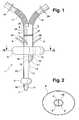
- eine Draufsicht auf einen Beatmungstubus;
- Fig. 2
- eine Schnittdarstellung gemäß der Linie II-II derFig. 1
- Fig. 1
- a plan view of a ventilation tube;
- Fig. 2
- 2 shows a sectional view along the line II-II of FIG. 1
Die Figuren sind sehr schematisch dargestellt, um die wesentlichenerfinderischen Merkmale zu verdeutlichen. In denDarstellungen sind die Dimensionen nur beispielhaft undnicht maßstäblich zu verstehen.The figures are shown very schematically to the essentialto illustrate inventive features. In theThe dimensions are only examples and representationsnot to be understood to scale.
Fig. 1 zeigt einen Beatmungstubus1 mit einem ersten undeinem zweiten Lumen2, 3, die im körperabgewandten Bereichdes Beatmungstubus 1 durch eine Trennwand4 voneinander getrennt sind. Im Gegensatz zum körperzugewandten Bereich istder Beatmungstubus 1 im körperabgewandten Bereich zweilumigausgebildet, wobei das zweite Lumen 3 am körperzugewandtenEnde des Beatmungstubus 1 offen endet. Im Endbereich istein aufblasbarer erster Ballon5 ausgebildet. Zum Aufblasendes ersten Ballons 5 ist eine Zuleitung6 vorgesehen, dieentlang des Beatmungstubus 1 bis zum ersten Ballon 5 geführtist. Nach dem ersten Ballon 5 verjüngt sich die Tubusspitze7 zum körperzugewandten offenen terminalen Endedes Beatmungstubus 1 hin und weist dadurch atraumatischeEigenschaften auf. Ferner ist das zweite Lumen 3 im körperzugewandtenBereich aus der Zeichenebene heraus leicht gekrümmt.Vom ersten Ballon 5 beabstandet ist ein zweiteraufblasbarer Ballon8 vorgesehen, der das erste und zweiteLumen 2, 3 umgibt. Zum Aufblasen des zweiten Ballons 8 isteine Zuleitung9 vorgesehen. Beide Zuleitungen 6, 9 mündenin eine nicht gezeigte Schnittstelle für einen Luerkonnektor.Das erste Lumen 2 endet unmittelbar am körperzugewandtenEnde des zweiten Ballons 8 und weist dort eine axialeMündung10 auf. Im Mündungsbereich ist ein als Zunge ausgebildeterAbstandshalter11 vorgesehen, die einenends mitihrer Basis12 an der Außenseite13 der Mündung 10 elastischbefestigt ist. Das freie Ende14 des Abstandshalters11 ist in der Fig. 1 vom Schaft15 des zweiten Lumens 3 geringbeabstandet gezeigt, kann jedoch auch auf dem Schaft15 aufliegen. Weiterhin ist am Schaft 15 im Mündungsbereicheine Erhebung16 vorgesehen, die ein in das erste Lumen 2einzuführendes Intubationshilfsmittel oder ein Bronchoskopführen kann. Am körperabgewandten Ende weisen die Lumina2,3 Ableitungsschenkel17, 18 auf, die vorzugsweise knickstabileRippenschläuche sind. Um Beatmungshilfsmittel anschließenzu können, sind 15mm-Konnektoren19, 20 vorgesehen.Eine Markierung21 zeigt an, wie weit der Beatmungstubus 1 eingeschoben werden kann. Über eine Graduierung21'bzw. Skala kann die Intubationstiefe abgelesen werden. DieAbstände der Graduierungsmarkierungen betragen 1 cm. In derWandung22 des Beatmungstubus 1 ist ein drittes Lumen fürdie Kapnographie vorgesehen, das einenends in einer Öffnung23 endet und anderenends in eine Gasabführleitung24 übergeht,die in eine nicht gezeigte Luerschnittstelle mündet.Am Außenumfang des Beatmungstubus 1 sind röntgenstrahlendichteMarkierungen25, 26 vorgesehen, über die die Lagedes platzierten Beatmungstubus 1 kontrolliert werden kann.Die Markierung 25 verläuft entlang des zweiten Lumens 3 unddie Markierung 26 verläuft entlang des ersten Lumens 2. DieMarkierung 26 setzt sich im beschriebenen Ausführungsbeispielentlang des Abstandshalters 11 fort.1 shows a
Fig. 2 zeigt einen Querschnitt gemäß der Linie II-II derFig. 1. Das erste und zweite Lumen 2, 3 sind im körperabgewandtenBereich, in dem sie im wesentlichen parallel verlaufen,durch eine Trennwand 4 voneinander getrennt. NachAußen werden sie von der Tubuswandung 22 begrenzt. DieQuerschnittsform des Beatmungstubus 1 ist in diesem Bereichvorzugsweise queroval. Die Tubuswandung 22 wird von demzweiten Ballon 8 umgeben, der im aufgeblasenen Zustand eineebenfalls vorzugsweise querovale Querschnittsform annimmt.FIG. 2 shows a cross section along the line II-II of FIG. 1. The first and
Je nach Verwendung des Beatmungstubus 1 wird das körperzugewandteEnde des Beatmungstubus 1 in die Trachea oder inden Ösophagus eingeführt. Der erste Ballon 5 wird dann aufgeblasen.Sitzt der Beatmungstubus 1 in der Trachea, erfolgtdie Beatmung über das zweite Lumen 3. Sitzt der Beatmungstubus1 dagegen im Ösophagus, dann erfolgt die Beatmungüber das erste Lumen 2. Der Rachenraum wird abgedichtet,indem der zweite Ballon 8 aufgeblasen wird. Im aufgeblasenen Zustand des zweiten Ballons 8 wird der Beatmungstubus1 in seiner platzierten Lage stabilisiert undzentriert. Über das erste Lumen 2 kann beispielsweise einBronchoskop in die Trachea eingeführt werden, wodurch derAbstandshalter 11 vom Schaft 15 weg gespreizt wird. Gleichzeitigkann bei Bedarf eine Magensonde über das zweite Lumen3 eingeführt werden.Depending on the use of the
Bei einem Beatmungstubus 1 mit einer Tubuswandung 22 zurwahlweisen Endotracheal- oder Ösophagusobturatorbeatmungmit einem ersten Lumen 2 und einem dazu im wesentlichen parallelverlaufenden zweiten Lumen 3, wobei ein erster dieTubuswandung 22 umgebender aufblasbarer Ballon 5 im Bereichdes körperzugewandten Endes des Beatmungstubus 1 und davonbeabstandet ein zweiter die Tubuswandung 22 umgebender aufblasbarerBallon 8 angeordnet ist, ist eine axiale Mündung10 des ersten Lumens 2 unmittelbar am körperzugewandten Endedes zweiten Ballons 8 angeordnet und ist der Beatmungstubus1 im Bereich des ersten Ballons 5 einlumig ausgebildet.Das Einführen von Intubationshilfsmitteln überdas erste Lumen 2 wird dadurch ermöglicht, so dass derBeatmungstubus vielfältig einsetzbar ist.In the case of a
Claims (9)
Translated fromGermanApplications Claiming Priority (2)
| Application Number | Priority Date | Filing Date | Title |
|---|---|---|---|
| DE10118605 | 2001-04-12 | ||
| DE10118605ADE10118605C1 (en) | 2001-04-12 | 2001-04-12 | Breathing tube, for selective endotracheal/esophagus-blocked breathing, where the axial opening of a first lumen is located directly after a second inflatable balloon, so in the vicinity the first balloon, the tube has a single lumen |
Publications (2)
| Publication Number | Publication Date |
|---|---|
| EP1249251A1true EP1249251A1 (en) | 2002-10-16 |
| EP1249251B1 EP1249251B1 (en) | 2004-06-23 |
Family
ID=7681591
Family Applications (1)
| Application Number | Title | Priority Date | Filing Date |
|---|---|---|---|
| EP02007102AExpired - LifetimeEP1249251B1 (en) | 2001-04-12 | 2002-03-28 | Inspiratory tube |
Country Status (4)
| Country | Link |
|---|---|
| EP (1) | EP1249251B1 (en) |
| JP (1) | JP3734763B2 (en) |
| DE (2) | DE10118605C1 (en) |
| ES (1) | ES2223985T3 (en) |
Families Citing this family (7)
| Publication number | Priority date | Publication date | Assignee | Title |
|---|---|---|---|---|
| AU2003246470B2 (en)* | 2003-07-28 | 2010-06-03 | Luiz Gonzaga Granja Filho | A probe for medical use |
| US7201168B2 (en)* | 2004-04-14 | 2007-04-10 | King Systems Corporation | Non-tracheal ventilation tube |
| US7921847B2 (en) | 2005-07-25 | 2011-04-12 | Intubix, Llc | Device and method for placing within a patient an enteral tube after endotracheal intubation |
| US8863746B2 (en) | 2005-07-25 | 2014-10-21 | Kim Technology Partners, LP | Device and method for placing within a patient an enteral tube after endotracheal intubation |
| EP2588177B1 (en)* | 2010-06-30 | 2020-01-01 | St. Michael's Hospital | System for patient-synchronized ventilatory assist with endotracheal through-flow |
| ITVI20120030A1 (en)* | 2012-02-07 | 2013-08-08 | Carboni Stefano Checcacci | TRACHEAL PRESIDIUM |
| EP4337289A4 (en)* | 2021-05-14 | 2025-05-14 | Airway Medix S.A. | Dual-balloon ventilation tube |
Citations (9)
| Publication number | Priority date | Publication date | Assignee | Title |
|---|---|---|---|---|
| US2862498A (en)* | 1957-06-14 | 1958-12-02 | Don J Weekes | Endotracheal tube |
| DE2120164A1 (en)* | 1971-04-24 | 1972-11-02 | Specht, Norbert, Dr.med., 2400 Lübeck | Ventilator |
| US4090518A (en)* | 1975-08-25 | 1978-05-23 | Elam James O | Esophago-pharyngeal airway |
| US4231365A (en)* | 1978-01-30 | 1980-11-04 | Scarberry Eugene N | Emergency resuscitation apparatus |
| EP0092618A1 (en)* | 1982-04-27 | 1983-11-02 | Patrick Albert Wallace | Esophageal-endotracheal airway |
| GB2168256A (en)* | 1984-12-14 | 1986-06-18 | Archibald Ian Jeremy Brain | Endobronchial tube assembly |
| AT384738B (en)* | 1985-02-20 | 1987-12-28 | Frass Michael Dr | VENTILATION TUBE |
| EP0747077A2 (en)* | 1995-06-07 | 1996-12-11 | Robert Maurice Raw | Endotracheal tube |
| US5873362A (en)* | 1997-03-18 | 1999-02-23 | Parker Medical Limited Partnership | Endotracheal tube |
- 2001
- 2001-04-12DEDE10118605Apatent/DE10118605C1/ennot_activeExpired - Fee Related
- 2002
- 2002-03-28EPEP02007102Apatent/EP1249251B1/ennot_activeExpired - Lifetime
- 2002-03-28ESES02007102Tpatent/ES2223985T3/ennot_activeExpired - Lifetime
- 2002-03-28DEDE50200533Tpatent/DE50200533D1/ennot_activeExpired - Lifetime
- 2002-04-10JPJP2002107729Apatent/JP3734763B2/ennot_activeExpired - Fee Related
Patent Citations (9)
| Publication number | Priority date | Publication date | Assignee | Title |
|---|---|---|---|---|
| US2862498A (en)* | 1957-06-14 | 1958-12-02 | Don J Weekes | Endotracheal tube |
| DE2120164A1 (en)* | 1971-04-24 | 1972-11-02 | Specht, Norbert, Dr.med., 2400 Lübeck | Ventilator |
| US4090518A (en)* | 1975-08-25 | 1978-05-23 | Elam James O | Esophago-pharyngeal airway |
| US4231365A (en)* | 1978-01-30 | 1980-11-04 | Scarberry Eugene N | Emergency resuscitation apparatus |
| EP0092618A1 (en)* | 1982-04-27 | 1983-11-02 | Patrick Albert Wallace | Esophageal-endotracheal airway |
| GB2168256A (en)* | 1984-12-14 | 1986-06-18 | Archibald Ian Jeremy Brain | Endobronchial tube assembly |
| AT384738B (en)* | 1985-02-20 | 1987-12-28 | Frass Michael Dr | VENTILATION TUBE |
| EP0747077A2 (en)* | 1995-06-07 | 1996-12-11 | Robert Maurice Raw | Endotracheal tube |
| US5873362A (en)* | 1997-03-18 | 1999-02-23 | Parker Medical Limited Partnership | Endotracheal tube |
Also Published As
| Publication number | Publication date |
|---|---|
| DE10118605C1 (en) | 2002-06-13 |
| ES2223985T3 (en) | 2005-03-01 |
| DE50200533D1 (en) | 2004-07-29 |
| JP3734763B2 (en) | 2006-01-11 |
| EP1249251B1 (en) | 2004-06-23 |
| JP2002315832A (en) | 2002-10-29 |
Similar Documents
| Publication | Publication Date | Title |
|---|---|---|
| DE69519241T2 (en) | Esophageal, tracheal, double-lumen breathing tube | |
| DE69327768T2 (en) | Emergency resuscitation device | |
| DE3246673C2 (en) | Device for creating an artificial airway | |
| EP2349427B1 (en) | Larynx mask having an esophageal passage | |
| DE69621583T2 (en) | THROAT MASK AND MECHANISM TO LIFT UP AN EPIGLOTTIS | |
| DE69728421T2 (en) | ARTIFICIAL VENTILATION DEVICE | |
| DE102011001325B4 (en) | Laryngeal tube and process for its preparation | |
| WO2010060224A1 (en) | Larynx mask having a connector | |
| DE19962985C1 (en) | Transpharyngeal tube comprises an end unit made of a material which is softer than the material of the tube shaft | |
| DE2828447B1 (en) | Laryngeal tube | |
| WO2010060227A1 (en) | Supraglottic tube for inserting a larynx mask | |
| DE10042172B4 (en) | Laryngomaske | |
| EP1249251B1 (en) | Inspiratory tube | |
| EP4271453B1 (en) | Ventilation device with voice air supply element | |
| DE19962372C2 (en) | Transpharyngealtubus | |
| EP3787722B1 (en) | Tracheal respiratory device having a sealing | |
| DE3542260A1 (en) | Bronchial catheter | |
| EP3727538B1 (en) | Tracheostomy cannula having a phonation opening | |
| EP1820527A1 (en) | Device for endoscopic examination of the act of swallowing | |
| DE102007011220B3 (en) | Medical multi-lumen device used as a breathing device for animals and humans comprises sections in the longitudinal direction with tubes extending through the reusable section up to a part of the disposable section | |
| DE3619692C2 (en) | ||
| DE102006060969B3 (en) | Respirator e.g. endotracheal tube, for use in e.g. veterinary medicine, has arrangement with distal area provided with balloon, where balloon has distal section provided to intrude in esophagus, and rods reversibly running by one tube | |
| DE102016002841A1 (en) | tracheostomy | |
| DE10361428B3 (en) | Breathing device used for emergency respiration of patients comprises a working channel tube providing a working channel extending from a proximal end into a space between proximal and distal closing bodies | |
| DE3323482C1 (en) | Auxiliary instrument for the introduction of tracheal tubes |
Legal Events
| Date | Code | Title | Description |
|---|---|---|---|
| PUAI | Public reference made under article 153(3) epc to a published international application that has entered the european phase | Free format text:ORIGINAL CODE: 0009012 | |
| AK | Designated contracting states | Kind code of ref document:A1 Designated state(s):AT BE CH CY DE DK ES FI FR GB GR IE IT LI LU MC NL PT SE TR | |
| AX | Request for extension of the european patent | Free format text:AL;LT;LV;MK;RO;SI | |
| 17P | Request for examination filed | Effective date:20020921 | |
| 17Q | First examination report despatched | Effective date:20030123 | |
| AKX | Designation fees paid | Designated state(s):DE ES FR IT | |
| GRAP | Despatch of communication of intention to grant a patent | Free format text:ORIGINAL CODE: EPIDOSNIGR1 | |
| GRAS | Grant fee paid | Free format text:ORIGINAL CODE: EPIDOSNIGR3 | |
| GRAA | (expected) grant | Free format text:ORIGINAL CODE: 0009210 | |
| AK | Designated contracting states | Kind code of ref document:B1 Designated state(s):DE ES FR IT | |
| REG | Reference to a national code | Ref country code:IE Ref legal event code:FG4D Free format text:GERMAN | |
| REF | Corresponds to: | Ref document number:50200533 Country of ref document:DE Date of ref document:20040729 Kind code of ref document:P | |
| REG | Reference to a national code | Ref country code:ES Ref legal event code:FG2A Ref document number:2223985 Country of ref document:ES Kind code of ref document:T3 | |
| REG | Reference to a national code | Ref country code:IE Ref legal event code:FD4D | |
| ET | Fr: translation filed | ||
| PLBE | No opposition filed within time limit | Free format text:ORIGINAL CODE: 0009261 | |
| STAA | Information on the status of an ep patent application or granted ep patent | Free format text:STATUS: NO OPPOSITION FILED WITHIN TIME LIMIT | |
| 26N | No opposition filed | Effective date:20050324 | |
| PGFP | Annual fee paid to national office [announced via postgrant information from national office to epo] | Ref country code:FR Payment date:20110401 Year of fee payment:10 Ref country code:IT Payment date:20110321 Year of fee payment:10 | |
| PGFP | Annual fee paid to national office [announced via postgrant information from national office to epo] | Ref country code:DE Payment date:20110428 Year of fee payment:10 Ref country code:ES Payment date:20110323 Year of fee payment:10 | |
| REG | Reference to a national code | Ref country code:FR Ref legal event code:ST Effective date:20121130 | |
| PG25 | Lapsed in a contracting state [announced via postgrant information from national office to epo] | Ref country code:FR Free format text:LAPSE BECAUSE OF NON-PAYMENT OF DUE FEES Effective date:20120402 | |
| REG | Reference to a national code | Ref country code:DE Ref legal event code:R119 Ref document number:50200533 Country of ref document:DE Effective date:20121002 | |
| PG25 | Lapsed in a contracting state [announced via postgrant information from national office to epo] | Ref country code:IT Free format text:LAPSE BECAUSE OF NON-PAYMENT OF DUE FEES Effective date:20120328 | |
| REG | Reference to a national code | Ref country code:ES Ref legal event code:FD2A Effective date:20130710 | |
| PG25 | Lapsed in a contracting state [announced via postgrant information from national office to epo] | Ref country code:ES Free format text:LAPSE BECAUSE OF NON-PAYMENT OF DUE FEES Effective date:20120329 | |
| PG25 | Lapsed in a contracting state [announced via postgrant information from national office to epo] | Ref country code:DE Free format text:LAPSE BECAUSE OF NON-PAYMENT OF DUE FEES Effective date:20121002 |