EP1247982B1 - Multiple ring compressor valve - Google Patents
Multiple ring compressor valveDownload PDFInfo
- Publication number
- EP1247982B1 EP1247982B1EP20020450058EP02450058AEP1247982B1EP 1247982 B1EP1247982 B1EP 1247982B1EP 20020450058EP20020450058EP 20020450058EP 02450058 AEP02450058 AEP 02450058AEP 1247982 B1EP1247982 B1EP 1247982B1
- Authority
- EP
- European Patent Office
- Prior art keywords
- catcher
- helical springs
- spring
- circumferential bars
- disc valve
- Prior art date
- Legal status (The legal status is an assumption and is not a legal conclusion. Google has not performed a legal analysis and makes no representation as to the accuracy of the status listed.)
- Expired - Lifetime
Links
- 239000004033plasticSubstances0.000claimsdescription7
- 229920003023plasticPolymers0.000claimsdescription7
- 229910000831SteelInorganic materials0.000claimsdescription6
- 239000010959steelSubstances0.000claimsdescription6
- 238000005299abrasionMethods0.000claimsdescription5
- 239000000463materialSubstances0.000claimsdescription5
- OKTJSMMVPCPJKN-UHFFFAOYSA-NCarbonChemical compound[C]OKTJSMMVPCPJKN-UHFFFAOYSA-N0.000claimsdescription4
- 239000004952PolyamideSubstances0.000claimsdescription3
- 229920003235aromatic polyamidePolymers0.000claimsdescription3
- 239000003822epoxy resinSubstances0.000claimsdescription3
- 229920002313fluoropolymerPolymers0.000claimsdescription3
- 239000004811fluoropolymerSubstances0.000claimsdescription3
- 239000010439graphiteSubstances0.000claimsdescription3
- 229910002804graphiteInorganic materials0.000claimsdescription3
- LNEPOXFFQSENCJ-UHFFFAOYSA-NhaloperidolChemical compoundC1CC(O)(C=2C=CC(Cl)=CC=2)CCN1CCCC(=O)C1=CC=C(F)C=C1LNEPOXFFQSENCJ-UHFFFAOYSA-N0.000claimsdescription3
- 239000005011phenolic resinSubstances0.000claimsdescription3
- 229920001643poly(ether ketone)Polymers0.000claimsdescription3
- 229920002647polyamidePolymers0.000claimsdescription3
- 229920000647polyepoxidePolymers0.000claimsdescription3
- 229920001169thermoplasticPolymers0.000claimsdescription3
- 229920001187thermosetting polymerPolymers0.000claimsdescription3
- 239000004416thermosoftening plasticSubstances0.000claimsdescription3
- 239000000945fillerSubstances0.000claimsdescription2
- 229920006389polyphenyl polymerPolymers0.000claimsdescription2
- 150000003568thioethersChemical class0.000claimsdescription2
- 241000531908AramidesSpecies0.000claims1
- 229910052799carbonInorganic materials0.000claims1
- 239000012744reinforcing agentSubstances0.000claims1
- 230000002093peripheral effectEffects0.000description14
- 238000009423ventilationMethods0.000description3
- 229920000049Carbon (fiber)Polymers0.000description2
- 239000004760aramidSubstances0.000description2
- 230000015572biosynthetic processEffects0.000description2
- 239000004917carbon fiberSubstances0.000description2
- 239000007789gasSubstances0.000description2
- 210000000056organAnatomy0.000description2
- 229920001568phenolic resinPolymers0.000description2
- 239000012779reinforcing materialSubstances0.000description2
- 239000004734Polyphenylene sulfideSubstances0.000description1
- 239000000654additiveSubstances0.000description1
- 230000007613environmental effectEffects0.000description1
- 238000004880explosionMethods0.000description1
- 230000002349favourable effectEffects0.000description1
- 238000009434installationMethods0.000description1
- 239000002245particleSubstances0.000description1
- 229920000069polyphenylene sulfidePolymers0.000description1
- 230000036316preloadEffects0.000description1
- 230000001681protective effectEffects0.000description1
- 238000013022ventingMethods0.000description1
Images
Classifications
- F—MECHANICAL ENGINEERING; LIGHTING; HEATING; WEAPONS; BLASTING
- F04—POSITIVE - DISPLACEMENT MACHINES FOR LIQUIDS; PUMPS FOR LIQUIDS OR ELASTIC FLUIDS
- F04B—POSITIVE-DISPLACEMENT MACHINES FOR LIQUIDS; PUMPS
- F04B39/00—Component parts, details, or accessories, of pumps or pumping systems specially adapted for elastic fluids, not otherwise provided for in, or of interest apart from, groups F04B25/00 - F04B37/00
- F04B39/10—Adaptations or arrangements of distribution members
- F04B39/1053—Adaptations or arrangements of distribution members the members being Hoerbigen valves
- Y—GENERAL TAGGING OF NEW TECHNOLOGICAL DEVELOPMENTS; GENERAL TAGGING OF CROSS-SECTIONAL TECHNOLOGIES SPANNING OVER SEVERAL SECTIONS OF THE IPC; TECHNICAL SUBJECTS COVERED BY FORMER USPC CROSS-REFERENCE ART COLLECTIONS [XRACs] AND DIGESTS
- Y10—TECHNICAL SUBJECTS COVERED BY FORMER USPC
- Y10T—TECHNICAL SUBJECTS COVERED BY FORMER US CLASSIFICATION
- Y10T137/00—Fluid handling
- Y10T137/7722—Line condition change responsive valves
- Y10T137/7837—Direct response valves [i.e., check valve type]
- Y10T137/7838—Plural
- Y10T137/7839—Dividing and recombining in a single flow path
Definitions
- the inventionrelates to an automatic annular plate valve for reciprocating compressors, with several individual, concentrically arranged between the valve seat and catcher Plastic ring plates as closing organs, which come from the peripheral webs of the catcher ago loaded by individual steel coil springs against the valve seat.
- valveshave long been known (see for example US 3 507 486 A, EP-345 245 B or US Pat. No. 3,536,094 A) and enable with specially flow-optimized flow cross sections compared to conventional designs known (flat steel plate valves or sheet steel ring valves) for a given ring width, a significant reduction in ventilation losses.
- the individual feathering of the individual ring platesalso makes possible in an advantageous manner A variety of influences on the opening and closing behavior of the valves.
- the ring platesare either on common Power distribution plates with a minimized number of coil springs with high power intensity feathered or individually, so directly by a over the circumference of the ring plates distributed attacking higher total number of coil springs of lesser strength.
- Object of the present inventionis to the mentioned disadvantages of the above mentioned known designs to avoid and in particular an automatic ring plate valve the type described to improve so that the individually feathered individual annular plates while maintaining the lowest possible ventilation losses safely out can be, without due to the formation of the springs due to the height or the associated dead space increases unreasonably.
- a ring plate valve of the type mentioned aboveachieved in that the diameter of the coil springs substantially equal to or slightly smaller than the width of the ring plates at the support point is the spiral springs, and that the coil springs on the side of the catcher in individual, sitting in blind hole-like recesses of the peripheral webs of the catcher and in open state of the ring plates the space occupied by the coil springs at least are supported and guided largely outwardly final spring pots.
- valve springs with a predefined force intensity over a given stroke rangecan at large spring outside diameter can be realized with a lower installation height than at small outer diameter.
- the spring pots of thermoplastic or thermosetting plasticspreferably polyamides, Polyphenylene sulfides, polyether ketones, phenolic resins or epoxy resins, which with filling or reinforcing materials, preferably carbon fibers, graphite, aramid or Fluoropolymers, are equipped to increase the abrasion resistance.
- relative movements between coil springs and surfaces in contactcan be used on both sides made of steel or similar hard materials to wear and subsequently to increased Risk of breakage.
- the spring potscan according to a further embodiment of the invention on their Floor have a vent, which claimed by the coil springs Space over at least one at the bottom of the recesses of the peripheral webs of the catcher provided, in the outer and / or inner circumference of the peripheral webs opening opening Vent.
- a ventwhich claimed by the coil springs Space over at least one at the bottom of the recesses of the peripheral webs of the catcher provided, in the outer and / or inner circumference of the peripheral webs opening opening Vent.
- the bottom of the spring potscan in a further embodiment of the invention for automatic Centering of the coil springs conically formed at least in the region of the support be, which improves the guidance and support of the coil springs in a simple manner.
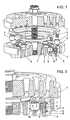
- Fig. 1shows an explosion shown partial section through an inventive annular plate valve
- Fig. 2shows a partial section through the same valve in the assembled state.
- the illustrated automatic annular plate valvehas three individual, concentric with each other between valve seat 1 and catcher 2 arranged plastic ring plates 3 as Closing organs, which from the catcher 2 ago by distributed over the circumference of individual Steel coil springs 4 are loaded against the valve seat 1.
- the diameter of the coil springs 4is substantially the same size or only slightly smaller than the width of the annular plates 3rd at the support of the coil springs 4, which at a certain required, predefined Force intensity over a given stroke range, the total spring length relatively low can be held.
- the coil springs 4are on the side of the catcher 2 in individual, in blind hole-like recesses 5 of the peripheral webs 6 of the catcher 2 sitting and in the The state of the ring plates 3 (FIG.
- the spring pots 7may be made of thermoplastic or thermosetting plastics, such as polyamides, polyphenyl sulfides, polyether ketones, phenolic resins or epoxy resins consist of fillers or reinforcing materials, such as carbon fibers, graphite, Aramid or fluoropolymers, to increase the abrasion resistance and to avoid Damage to the springs are equipped.
- thermoplastic or thermosetting plasticssuch as polyamides, polyphenyl sulfides, polyether ketones, phenolic resins or epoxy resins consist of fillers or reinforcing materials, such as carbon fibers, graphite, Aramid or fluoropolymers, to increase the abrasion resistance and to avoid Damage to the springs are equipped.
- the spring pots 7have at their bottom 8 a vent opening 9 (see the cut spring cup 7 in Fig. 2), which claimed by the coil springs 4 Space over at least one at the bottom of the recesses 5 of the peripheral webs 6 of the catcher 2 provided, here in the outer and inner circumference of the circumferential webs 6 opening Bleed opening 10.
- This opening 10is formed here by a at the bottom of the recess 5 provided stepped area whose diameter is still at least slightly larger than the width of the peripheral webs 6 at this point, so here the entire blind hole-like recess 5 respectively to the inner and outer peripheral surface of the circumferential webs 6 of the catcher is open.
- the bottom 8 of the spring pots 7is not in this case the smallness of the representation clearly recognizable way on the inside for automatic centering of the coil springs 4 conically formed at least in the region of the support, bringing the steadily under Preload standing springs 4 are simply positioned in the spring cups 7.
- protective spring pots 7so the diameter of the individual coil springs 4 is increased to the predetermined by the width of the ring plates 3 measure be, at the same time the fluidically advantageous taper of the circumferential webs 6 of the catcher 2 in the flow direction away from the valve seat can be maintained without that it at the catcher side bearing point of the coil springs 4 to Abnützungsproblemen could come.
- the springsare from the gas flowed space, in which high Flow rates are present, shielded and in direct contact with the subsidized medium or with entrained in this abrasive or polluting Particles avoided.
Landscapes
- Engineering & Computer Science (AREA)
- Mechanical Engineering (AREA)
- General Engineering & Computer Science (AREA)
- Springs (AREA)
- Compressor (AREA)
- Check Valves (AREA)
- Lift Valve (AREA)
Description
Translated fromGermanDie Erfindung betrifft ein selbsttätiges Ringplattenventil für Kolbenkompressoren, mitmehreren einzelnen, konzentrisch zueinander zwischen Ventilsitz und Fänger angeordnetenKunststoff-Ringplatten als Schließorganen, welche von den Umfangsstegen des Fängers hermittels einzelner Stahl-Spiralfedern gegen den Ventilsitz belastet sind.The invention relates to an automatic annular plate valve for reciprocating compressors, withseveral individual, concentrically arranged between the valve seat and catcherPlastic ring plates as closing organs, which come from the peripheral webs of the catcher agoloaded by individual steel coil springs against the valve seat.
Derartige Ventile sind seit langem bekannt (siehe beispielsweise US 3 507 486 A, EP-345 245 B oderUS 3 536 094 A) und ermöglichen mit speziell strömungsoptimierten Durchflussquerschnittengegenüber üblichen bekannten Konstruktionen (ebene Stahlplattenventile bzw. Stahlblech-Ringventile)bei vorgegebener Ringbreite eine wesentliche Verringerung der Ventilationsverluste.Die individuelle Befederung der einzelnen Ringplatten ermöglicht weiters in vorteilhafterWeise verschiedenste Einflussnahmen auf das Öffnungs- und Schließverhalten der Ventile.Bei den bekannten Ausführungen werden die Ringplatten entweder über gemeinsameKraftverteilerplatten mit einer minimierten Anzahl von Schraubenfedern mit hoher Kraftintensitätbefedert oder aber individuell, also direkt durch eine über den Umfang der Ringplattenverteilt angreifende höhere Gesamtzahl von Schraubenfedern geringerer Kraftintensität.Such valves have long been known (see for
Im erstgenannten Fall ergeben sich durch die Kraftverteilerplatte zumeist Problemefür die Führung der einzelnen Ringplatten, da dafür entweder die Kraftverteilerplatte speziellausgeführt werden muss oder aber Führungselemente des Fängers durch die Kraftverteilerplattehindurchragen müssen, womit ein nicht zu vernachlässigender Anteil der durchströmtenQuerschnittfläche der Kraftverteilerplatte für eben diese Führungselemente verloren gehtund die Ventilationsverluste ansteigen. Im zweitgenannten Falle können die einzelnen Ringplattenzwar ohne weiteres über den gesamten Hub geführt werden, wobei sich aus der konstruktivenGestaltung des Fängers aber die Problematik ergibt, dass nur Federn mit relativgeringem Außendurchmesser untergebracht werden können, da ansonsten die Federn überdie Umfangsstege des Fängers hinaus in den Strömungsquerschnitt ragen und an den Endwindungenkeine satte Auflagefläche haben, was lokale Überbeanspruchung bedingt. Beikleinem Außendurchmesser der einzelnen Spiralfedern ist zur Erzielung der vorgegebenenFederkraft, unter Einhaltung der zulässigen Werkstoffbeanspruchung bei dynamischer Belastung, eine sehr hohe Windungsanzahl erforderlich, welche wiederum eine hohe Gesamtfederlängebedingt, da die Federdrahtdurchmesser nicht beliebig verringert werden können.Dies bedeutet aber einen entscheidenden Anstieg der gesamten Bauhöhe, welche die Anwendbarkeitin engen Ventilnestern grundsätzlich einschränkt oder aber bedingt durch diesich ergebende hohe Schadraumausprägung bei Saugventilen die Liefermenge reduziert.In the former case arise through the power distribution plate mostly problemsfor the guidance of the individual ring plates, because either the power distribution plate specificallymust be performed or guide elements of the catcher through the power distribution platehave to protrude, which a not insignificant proportion of flowed throughCross-sectional area of the power distribution plate is lost for just these guide elementsand the ventilation losses increase. In the second case, the individual ring platesAlthough easily be performed over the entire stroke, resulting from the constructiveDesign of the catcher but the problem arises that only springs with relativesmall outer diameter can be accommodated, otherwise the springs overthe peripheral webs of the catcher protrude into the flow cross-section and at the end turnshave no rich bearing surface, which causes local overuse. atsmall outer diameter of the individual coil springs is to achieve the predeterminedSpring force, while maintaining the permissible material stress under dynamic load,a very high number of turns required, which in turn has a high overall spring lengthconditionally, since the spring wire diameter can not be arbitrarily reduced.However, this means a decisive increase in the overall height, which the applicabilityin narrow valve nests in principle limits or due to theresulting high Schadraumausprägung with suction valves reduces the delivery quantity.
Aufgabe der vorliegenden Erfindung ist es, die erwähnten Nachteile der eingangsgenannten bekannten Ausführungen zu vermeiden und insbesonders ein selbsttätiges Ringplattenventilder beschriebenen Bauart so zu verbessern, dass die individuell befederteneinzelnen Ringplatten unter Beibehaltung möglichst geringer Ventilationsverluste sicher geführtwerden können, ohne dass durch die Ausbildung der Federn bedingt die Bauhöhe bzw.der damit einhergehende Schadraum unbotmäßig ansteigt.Object of the present invention is to the mentioned disadvantages of the abovementioned known designs to avoid and in particular an automatic ring plate valvethe type described to improve so that the individually featheredindividual annular plates while maintaining the lowest possible ventilation losses safely outcan be, without due to the formation of the springs due to the height orthe associated dead space increases unreasonably.
Diese Aufgabe wird gemäß der vorliegenden Erfindung bei einem Ringplattenventilder eingangs genannten Art dadurch gelöst, dass der Durchmesser der Spiralfedern im wesentlichengleich groß wie bzw. geringfügig kleiner als die Breite der Ringplatten an der Auflagestelleder Spiralfedern ist, und dass die Spiralfedern auf der Seite des Fängers in einzelnen,in sacklochartigen Ausnehmungen der Umfangsstege des Fängers sitzenden und imoffenen Zustand der Ringplatten den von den Spiralfedern beanspruchten Raum zumindestweitgehend nach außen abschließenden Federtöpfen abgestützt und geführt sind. Ventilfedernmit einer vordefinierten Kraftintensität über einen gegebenen Hubbereich können beigroßem Federaußendurchmesser mit einer geringeren Einbauhöhe realisiert werden als beikleinem Außendurchmesser. Im letzteren Falle ist nämlich zur Erzielung der vorgegebenenFederkraft unter Einhaltung der zulässigen Werkstoffbeanspruchung bei dynamischer Belastungeine sehr hohe Windungszahl erforderlich, welche wiederum die Gesamtlänge der Federentsprechend vergrößert. Nachdem für günstige Strömungsverhältnisse die Breite dereinzelnen Ringplatten im wesentlichen der Breite der zugeordneten Fängerstege entspricht,könnten einfache Federnester in den Umfangsstegen des Fängers den fängerseitigen Federendenbei größerem Durchmesser nur eine teilweise Abstützung bieten, was unbeherrschbare Probleme bei den üblicherweise vorliegenden hochdynamischen Beanspruchungenderartiger Anordnungen bieten würde. Dies wird nun gemäß der Erfindung durchdie erwähnten Federtöpfe in den sacklochartigen Ausnehmungen der Umfangsstege desFängers verhindert, welche den fängerseitigen Federenden eine sichere Abstützung auchbei den üblicherweise bei größerer Entfernung von den Ringplatten weg aus Strömungsgründendünner werdenden Fänger-Umfangsstegen ermöglicht. Zusätzlich sind die einzelnenSpiralfedern in diesen Federtöpfen sicher geführt und vor Umgebungseinflüssen beispielsweisedurch heiße oder aggressive zu steuernde Gase bestens geschützt.This object is achieved according to the present invention in a ring plate valveof the type mentioned above achieved in that the diameter of the coil springs substantiallyequal to or slightly smaller than the width of the ring plates at the support pointis the spiral springs, and that the coil springs on the side of the catcher in individual,sitting in blind hole-like recesses of the peripheral webs of the catcher and inopen state of the ring plates the space occupied by the coil springs at leastare supported and guided largely outwardly final spring pots. valve springswith a predefined force intensity over a given stroke range can atlarge spring outside diameter can be realized with a lower installation height than atsmall outer diameter. In the latter case, namely to achieve the predeterminedSpring force in compliance with the permissible material stress under dynamic loada very high number of turns is required, which in turn reduces the total length of the springincreased accordingly. After for favorable flow conditions the width of theindividual annular plates corresponds substantially to the width of the associated catcher webs,simple spring tester could in the peripheral webs of the catcher the spring side spring endswith larger diameter offer only a partial support, which uncontrollableProblems with the usually present high dynamic loadswould offer such arrangements. This is now according to the invention bythe mentioned spring pots in the blind hole-like recesses of the peripheral webs of theFängers prevents which the catcher side spring ends a secure support alsoat the usually at a greater distance away from the ring plates away for flow reasonsthinner catcher circumferential webs allows. In addition, the individualSpiral springs safely guided in these spring pots and against environmental influences, for exampleWell protected by hot or aggressive gases to be controlled.
In besonders bevorzugter Ausgestaltung der Erfindung ist vorgesehen, dass die Federtöpfeaus thermoplastischen oder duroplastischen Kunststoffen, vorzugsweise Polyamiden,Polyphenylsulfiden, Polyetherketonen, Phenolharzen oder Epoxydharzen bestehen,welche mit Füll bzw. Verstärkungsstoffen, vorzugsweise Kohlefasern, Graphit, Aramid oderFluorpolymeren, zur Erhöhung der Abriebsresistenz ausgerüstet sind. Relativbewegungenzwischen Spiralfedern und in Kontakt stehenden Flächen (Ringplatte, Federnestboden undim wesentlichen zylindrische Federnestseitenflächen) können bei beidseitigen Ausführungenaus Stahl oder ähnlichen harten Werkstoffen zu Verschleiß und in weiterer Folge zu erhöhterBruchgefahr führen. Durch die Ausbildung der Federtöpfe aus abriebresistenten und verschleißreduzierendenKunststoffen mit speziellen Additiven sind die Spiralfedern an allenpotentiellen Kontaktflächen vor Abrieb bestens geschützt. Zum Einen ist dies bei den direktmit den Spiralfedern in Kontakt stehenden Flächen am Federtopfboden und an der Kunststoff-Ringplatteder Fall; zum Anderen trifft dies auch an potentiellen Kontaktflächen zwischenFeder-Mantelfläche und Federtopf-Innenmantelfläche für den Fall zu, dass währendder Ringplattenbewegung eine Rotation derselben eingeleitet wird, welche eine Auslenkungder Federenden in Umfangsrichtung nach sich zieht. Gleichzeitig wird dadurch der Fänger anden Stellen potentieller Mikrobewegungen durch die Kunststoff-Federtöpfe vor Verschleißgeschützt.In a particularly preferred embodiment of the invention, it is provided that the spring potsof thermoplastic or thermosetting plastics, preferably polyamides,Polyphenylene sulfides, polyether ketones, phenolic resins or epoxy resins,which with filling or reinforcing materials, preferably carbon fibers, graphite, aramid orFluoropolymers, are equipped to increase the abrasion resistance. relative movementsbetween coil springs and surfaces in contact (ring plate, spring floor andessentially cylindrical spring side surfaces) can be used on both sidesmade of steel or similar hard materials to wear and subsequently to increasedRisk of breakage. Due to the design of the spring pots from abrasion resistant and wear-reducingPlastics with special additives are the coil springs at allpotential contact surfaces are well protected against abrasion. For one, this is the directwith the coil springs in contact surfaces on the spring pot bottom and on the plastic ring platethe case; On the other hand, this also applies to potential contact areas betweenSpring shell surface and spring cup inner circumferential surface in the event that duringthe ring plate movement is initiated a rotation thereof, which is a deflectionpulls the spring ends in the circumferential direction by itself. At the same time, this will cause the catcherthe locations of potential micromotion through the plastic spring pots from wearprotected.
Die Federtöpfe können nach einer weiteren Ausgestaltung der Erfindung an ihremBoden eine Entlüftungsöffnung aufweisen, welche den von den Spiralfedern beanspruchtenRaum über zumindest eine am Boden der Ausnehmungen der Umfangsstege des Fängersvorgesehene, in den Außen- und/oder Innenumfang der Umfangsstege ausmündende Öffnungentlüften. Damit ist auf sehr einfache Weise sichergestellt, dass beispielsweise Druckwellenim Federnest, welche durch die Ringplattendynamik initiiert werden, vermieden sind.Zusätzlich können die in das Federnest eintretenden Ablagerungen von Öl, Schmutz oderdergleichen über den genannten Entlüftungspfad abgeführt werden.The spring pots can according to a further embodiment of the invention on theirFloor have a vent, which claimed by the coil springsSpace over at least one at the bottom of the recesses of the peripheral webs of the catcherprovided, in the outer and / or inner circumference of the peripheral webs opening openingVent. This ensures in a very simple manner that, for example, pressure wavesin the spring test, which are initiated by the ring plate dynamics are avoided.In addition, the deposits of oil, dirt orThe like be removed via the said venting path.
Im letztgenannten Zusammenhang ist eine weitere Ausgestaltung der Erfindung vonbesonderem Vorteil, gemäß welcher zur Bildung der in den Außen- und Innenumfang derUmfangsstege des Fängers ausmündenden Öffnungen die Ausnehmungen in den Umfangsstegendes Fängers am Boden einen abgestuften Bereich aufweisen, dessen Durchmessernoch größer als die Breite der Umfangsstege an dieser Stelle ist. Dies ermöglicht eine sehreinfache Herstellung der erforderlichen Entlüftungsöffnungen, wobei die Federtöpfe nochsicher an der Abstufung der Ausnehmung am Boden aufliegen können.In the latter context, a further embodiment of the invention ofparticular advantage, according to which the formation of the outer and inner circumference ofCircumferential webs of the catcher opening openings, the recesses in the peripheral websthe catcher on the ground have a stepped portion whose diametereven greater than the width of the peripheral webs at this point. This allows a loteasy preparation of the required vents, with the spring pots stillcan safely rest on the gradation of the recess on the ground.
Der Boden der Federtöpfe kann in weiterer Ausgestaltung der Erfindung zur selbsttätigenZentrierung der Spiralfedern zumindest im Bereich von deren Abstützung konisch ausgebildetsein, was auf einfache Weise die Führung und Abstützung der Spiralfedern verbessert.The bottom of the spring pots can in a further embodiment of the invention for automaticCentering of the coil springs conically formed at least in the region of the supportbe, which improves the guidance and support of the coil springs in a simple manner.
Die Erfindung wird im folgenden noch anhand des in der Zeichnung teilweise schematischdargestellten Ausführungsbeispiels näher erläutert. Fig. 1 zeigt dabei einen explosionsartigdargestellten teilweisen Schnitt durch ein erfindungsgemäßes Ringplattenventil undFig. 2 zeigt einen Teilschnitt durch das gleiche Ventil im zusammengebauten Zustand.The invention will be described in more detail below with reference to the drawing in which partiallyillustrated embodiment illustrated. Fig. 1 shows an explosionshown partial section through an inventive annular plate valve andFig. 2 shows a partial section through the same valve in the assembled state.
Das dargestellte selbsttätige Ringplattenventil weist drei einzelne, konzentrisch zueinanderzwischen Ventilsitz 1 und Fänger 2 angeordnete Kunststoff-Ringplatten 3 alsSchließorgane auf, welche vom Fänger 2 her mittels über den Umfang verteilter einzelnerStahl-Spiralfedern 4 gegen den Ventilsitz 1 belastet sind. Der Durchmesser der Spiralfedern 4 ist im wesentlichen gleich groß bzw. nur geringfügig kleiner als die Breite der Ringplatten 3an der Auflagestelle der Spiralfedern 4, womit bei einer bestimmten benötigten, vordefiniertenKraftintensität über einen gegebenen Hubbereich die Gesamtfederlänge relativ geringgehalten werden kann. Die Spiralfedern 4 sind auf der Seite des Fängers 2 in einzelnen, insacklochartigen Ausnehmungen 5 der Umfangsstege 6 des Fängers 2 sitzenden und imfenen Zustand der Ringplatten 3 (Fig. 2 zeigt den geschlossenen Zustand) den von den Spiralfedern4 beanspruchten Raum zumindest weitgehend nach außen abschließenden Federtöpfen7 abgestützt und geführt, womit auch bei den wie dargestellt sich von den Ringplatten3 weg nach unten verjüngenden Umfangsstegen 6 eine sichere und ganzflächige Abstützungder fängerseitigen Enden der Spiralfedern 4 möglich ist und die Federn selbst gut geschütztund nicht beispielsweise heißen oder aggressiven zu steuernden Medien ausgesetzt sind.The illustrated automatic annular plate valve has three individual, concentric with each otherbetween valve seat 1 and
Die Federtöpfe 7 können aus thermoplastischen oder duroplastischen Kunststoffen,wie etwa Polyamiden, Polyphenylsulfiden, Polyetherketonen, Phenolharzen oder Epoxydharzenbestehen, welche mit Füll- bzw. Verstärkungsstoffen, wie etwa Kohlefasern, Graphit,Aramid oder Fluorpolymeren, zur Erhöhung der Abriebresistenz und zur Vermeidung vonBeschädigung der Federn ausgerüstet sind.The
Die Federtöpfe 7 weisen an ihrem Boden 8 eine Entlüftungsöffnung 9 auf (siehe dengeschnittenen Federtopf 7 in Fig. 2), welche den von den Spiralfedern 4 beanspruchtenRaum über zumindest eine am Boden der Ausnehmungen 5 der Umfangsstege 6 des Fängers2 vorgesehene, hier in den Außen- und Innenumfang der Umfangsstege 6 ausmündendeÖffnung 10 entlüften. Diese Öffnung 10 ist hier gebildet durch einen am Boden der Ausnehmung5 vorgesehenen abgestuften Bereich, dessen Durchmesser noch zumindest geringfügiggrößer als die Breite der Umfangsstege 6 an dieser Stelle ist, womit hier die gesamtesacklochartige Ausnehmung 5 jeweils zur inneren und äußeren Umfangsfläche der Umfangsstege6 des Fängers hin offen ist.The
Der Boden 8 der Federtöpfe 7 ist in hier zufolge der Kleinheit der Darstellung nichtdeutlich erkennbarer Weise auf der Innenseite zur selbsttätigen Zentrierung der Spiralfedern 4 zumindest im Bereich von deren Abstützung konisch ausgebildet, womit die stetig unterVorspannung stehenden Federn 4 in den Federtöpfen 7 einfach positioniert sind.The
Beim Zusammenbau des Ringplattenventils können die Federtöpfe 7 beispielsweiseeinfach dadurch in den zugehörigen Ausnehmungen 5 der Umfangsstege 6 des Fängersgehalten werden, dass der Außendurchmesser leicht größer gewählt wird als der Durchmesserder Ausnehmung, womit insbesonders bei Kunststoff-Federtöpfen sehr leicht und einfacheine Klemmung erzielbar ist. Durch die die Federn wie beschrieben auch vor schädlichenAußeneinflüssen schützenden Federtöpfe 7 kann also der Durchmesser der einzelnen Spiralfedern4 bis auf das durch die Breite der Ringplatten 3 vorgegebenen Maß vergrößertwerden, wobei gleichzeitig die strömungstechnisch vorteilhafte Verjüngung der Umfangsstege6 des Fängers 2 in Strömungsrichtung weg vom Ventilsitz beibehalten werden kann, ohnedass es an der fängerseitigen Auflagestelle der Spiralfedern 4 zu Abnützungsproblemenkommen könnte. Die Federn sind vom gasdurchströmten Raum, in welchem hoheStrömungsgeschwindigkeiten vorliegen, abgeschirmt und direkter Kontakt mit demgeförderten Medium bzw. mit in diesem mitgeführten abrasivem oder verschmutzendenPartikeln vermieden.When assembling the annular plate valve, the
Claims (5)
- An automatic annular disc valve for piston compressors, comprising severalindividual plastics material annular discs (3) as closing members, arrangedconcentrically to one another between valve seat (1) and catcher (2), which are loadedagainst the valve seat (1) from the circumferential bars (6) of the catcher (2) by meansof individual steel helical springs (4),characterised in that the diameter of the helicalsprings (4) is substantially the same size as, to slightly smaller than, the width of theannular discs (3) at the point of support of the helical springs (4), andin that thehelical springs (4) are supported and guided on the side of the catcher (2) in individualspring cups (7) which are seated in blind hole-type recesses (5) of the circumferentialbars (6) of the catcher (2) and, in the open state of the annular discs (3), close at leastlargely outwardly the space taken up by the helical springs (4).
- An annular disc valve according to Claim 1,characterised in that the springcups are made of thermoplastic or thermosetting plastics materials, preferablypolyamides, polyphenyl sulphides, polyether ketones, phenol resins or epoxy resins,which are provided with fillers or reinforcing agents, preferably carbon fibres,graphite, aramide or fluoropolymers, to increase the abrasion resistance.
- An annular disc valve according to Claim 1 or 2,characterised in that, at theirbase (8), the spring cups (7) have an air vent (9), which vent the space taken up by thehelical springs (4) via at least one opening (10) provided at the base of the recesses (5)of the circumferential bars (6) of the catcher (2) and opening into the exterior and/orthe interior circumference of the circumferential bars (6).
- An annular disc valve according to Claim 3,characterised in that, in order toform openings (10) opening into the exterior and interior circumference of thecircumferential bars (6) of the catcher (2), the recesses (5) in the circumferential bars(6) of the catcher (2) have a stepped region at the base, the diameter of which is evenlarger than the width of the circumferential bars (6) at this point.
- An annular disc valve according to one or more of Claims 1 to 4,characterisedin that the base (8) of the spring cups (7) is designed so as to be conical for automaticcentring of the helical springs (4) at least in the region of their support.
Applications Claiming Priority (2)
| Application Number | Priority Date | Filing Date | Title |
|---|---|---|---|
| AT5392001 | 2001-04-04 | ||
| AT5392001 | 2001-04-04 |
Publications (3)
| Publication Number | Publication Date |
|---|---|
| EP1247982A2 EP1247982A2 (en) | 2002-10-09 |
| EP1247982A3 EP1247982A3 (en) | 2003-11-26 |
| EP1247982B1true EP1247982B1 (en) | 2005-02-23 |
Family
ID=3676291
Family Applications (1)
| Application Number | Title | Priority Date | Filing Date |
|---|---|---|---|
| EP20020450058Expired - LifetimeEP1247982B1 (en) | 2001-04-04 | 2002-03-13 | Multiple ring compressor valve |
Country Status (5)
| Country | Link |
|---|---|
| US (1) | US20020144733A1 (en) |
| EP (1) | EP1247982B1 (en) |
| JP (1) | JP2003035262A (en) |
| CN (1) | CN1379183A (en) |
| DE (1) | DE50202301D1 (en) |
Families Citing this family (19)
| Publication number | Priority date | Publication date | Assignee | Title |
|---|---|---|---|---|
| US6817846B2 (en)* | 2002-06-13 | 2004-11-16 | Dresser-Rand Company | Gas compressor and method with improved valve assemblies |
| ITGE20040116A1 (en)* | 2004-12-22 | 2005-03-22 | Dott Ing Mario Cozzani Srl | VALVE, IN PARTICULAR FOR COMPRESSORS. |
| US7506662B2 (en)* | 2005-09-30 | 2009-03-24 | Walter Tuymer | One-way fluid valve |
| AT504650B1 (en) | 2007-03-22 | 2008-07-15 | Hoerbiger Kompressortech Hold | Self-actuated suction and pressure valve e.g. ring valve, for compressor, has valve spring loading sealing element against valve seat, and spring cup whose inner contour opens in shape of calotte from spring cup base |
| USD675330S1 (en)* | 2010-07-23 | 2013-01-29 | Apollo Industrial Co., Ltd. | Plate valve for bubble generator |
| JP5710183B2 (en)* | 2010-09-07 | 2015-04-30 | 株式会社不二工機 | Pilot operated bidirectional solenoid valve |
| EP2703647B1 (en)* | 2012-08-31 | 2017-10-04 | Burckhardt Compression AG | Poppet valve for a compressor |
| CN104806481A (en)* | 2014-01-24 | 2015-07-29 | 上海华林工业气体有限公司 | CO compressor air valve for HYCO device |
| WO2016061522A1 (en)* | 2014-10-16 | 2016-04-21 | Gardner Denver, Inc. | Compressor head |
| EP3362713B1 (en)* | 2015-10-12 | 2019-08-28 | Burckhardt Compression AG | Poppet valve |
| USD824426S1 (en)* | 2015-10-26 | 2018-07-31 | Delaware Capital Formation, Inc. | Reciprocating gas compressor valve |
| USD813912S1 (en)* | 2015-10-26 | 2018-03-27 | Delaware Capital Formation, Inc. | Reciprocating gas compressor valve |
| USD841055S1 (en)* | 2015-10-26 | 2019-02-19 | Delaware Capital Formation, Inc. | Reciprocating gas compressor valve |
| USD816122S1 (en)* | 2015-10-26 | 2018-04-24 | Delaware Capital Formation, Inc. | Sealing element for reciprocating gas compressor valve |
| WO2017074940A1 (en) | 2015-10-26 | 2017-05-04 | Delaware Capital Formation, Inc. | Reciprocating gas compressor valve |
| CN107355369B (en)* | 2016-05-10 | 2019-04-12 | 上海迪瓦流体控制科技有限公司 | Bidirectional buffering and Compressor Valve control system containing it |
| USD816719S1 (en)* | 2016-10-25 | 2018-05-01 | Delaware Capital Formation, Inc. | Sealing element for reciprocating gas compressor valve |
| EP3330540B1 (en)* | 2016-12-05 | 2019-06-19 | Burckhardt Compression AG | Poppet valve |
| WO2019170883A1 (en)* | 2018-03-08 | 2019-09-12 | Burckhardt Compression Ag | Plate valve and method for operating same |
Family Cites Families (18)
| Publication number | Priority date | Publication date | Assignee | Title |
|---|---|---|---|---|
| DE202609C (en)* | ||||
| US1081803A (en)* | 1913-05-13 | 1913-12-16 | Stephen Evans Alley | Automatic valve of disk form. |
| US1222321A (en)* | 1914-11-17 | 1917-04-10 | Ingersoll Rand Co | Valve for compressors and pumps. |
| US2000691A (en)* | 1931-04-02 | 1935-05-07 | Chicago Pneumatic Tool Co | Compressor discharge valve |
| US2690763A (en)* | 1949-05-24 | 1954-10-05 | Seligman Arthur | Compressor valve |
| US2703583A (en)* | 1949-05-24 | 1955-03-08 | Seligman Arthur | Valve for compressors |
| AT243420B (en)* | 1963-05-08 | 1965-11-10 | Enfo Grundlagen Forschungs Ag | Multi-ring valve |
| US3507486A (en)* | 1967-11-13 | 1970-04-21 | Bernard L Schwaller | Dual stage compressor spring |
| US3536094A (en) | 1968-03-12 | 1970-10-27 | Flavious E Manley Jr | Compressor valve |
| US3656500A (en)* | 1970-05-18 | 1972-04-18 | Worthington Corp | Check valve |
| US3829253A (en)* | 1972-12-27 | 1974-08-13 | S Bunn | Plate valve structure |
| US4228820A (en)* | 1977-12-30 | 1980-10-21 | The Yorde Machine Products Company | Seat guided poppet valve having flow and dampening control means |
| US4350179A (en)* | 1980-09-26 | 1982-09-21 | Bunn Stuart E | Valve assembly with relief groove |
| US4398559A (en)* | 1980-09-26 | 1983-08-16 | Ball Vavle Company, Inc. | Valve member and assembly with inlet and outlet pressure relief grooves |
| US4489752A (en)* | 1982-09-28 | 1984-12-25 | Compressor Valve Services, Inc. | Guard guided multiple element flow configured poppet valve |
| EP0345245B1 (en) | 1988-05-31 | 1993-10-13 | Hoerbiger Ventilwerke Aktiengesellschaft | Ring valve |
| US5511583A (en)* | 1995-01-24 | 1996-04-30 | Dover Resources, Inc. | Compressor valve |
| AT412302B (en)* | 2000-03-28 | 2004-12-27 | Hoerbiger Ventilwerke Gmbh | AUTOMATIC VALVE |
- 2002
- 2002-03-13EPEP20020450058patent/EP1247982B1/ennot_activeExpired - Lifetime
- 2002-03-13DEDE50202301Tpatent/DE50202301D1/ennot_activeExpired - Fee Related
- 2002-03-26USUS10/105,632patent/US20020144733A1/ennot_activeAbandoned
- 2002-04-03JPJP2002101241Apatent/JP2003035262A/enactivePending
- 2002-04-04CNCN02105444Apatent/CN1379183A/enactivePending
Also Published As
| Publication number | Publication date |
|---|---|
| US20020144733A1 (en) | 2002-10-10 |
| EP1247982A2 (en) | 2002-10-09 |
| DE50202301D1 (en) | 2005-03-31 |
| CN1379183A (en) | 2002-11-13 |
| EP1247982A3 (en) | 2003-11-26 |
| JP2003035262A (en) | 2003-02-07 |
Similar Documents
| Publication | Publication Date | Title |
|---|---|---|
| EP1247982B1 (en) | Multiple ring compressor valve | |
| EP0300989B1 (en) | Plate valve for a compressor | |
| DE4115708C2 (en) | Ball roller unit | |
| DE102014015946A1 (en) | Cooling duct cover and piston provided with a cooling channel cover | |
| DE102006037307A1 (en) | Compressed air supply device for a commercial vehicle and air dryer cartridge | |
| DE102007046248A1 (en) | Fluid dynamic bearing with recirculation channel | |
| EP2876303B1 (en) | Lifting gripper for a valve element of a compressor valve | |
| AT504650B1 (en) | Self-actuated suction and pressure valve e.g. ring valve, for compressor, has valve spring loading sealing element against valve seat, and spring cup whose inner contour opens in shape of calotte from spring cup base | |
| DE102010049493A1 (en) | Tilting pad used as tilting bearing for jet propulsion device for watercraft, has bearing element that is mounted at preset space from sections that are arranged at back side | |
| DE602004011811T2 (en) | COOLING CHANNEL COVER FOR ONE PIECE PISTON OF A COMBUSTION ENGINE | |
| DE69813614T2 (en) | PRELOADED, DAMPED BEARING ARRANGEMENT | |
| WO2018114644A1 (en) | Valve | |
| DE102014015947A1 (en) | Cooling duct cover and piston provided with a cooling channel cover | |
| DE102009056351A1 (en) | Strut bearing arrangement has strut bearing for receiving axially directed forces, where strut bearing is formed from lower bearing frame and sliding element | |
| DE102022211165A1 (en) | Check valve assembly for a hydraulic unit of a motor vehicle braking system | |
| DE10059954B4 (en) | check valve | |
| DE102022100737A1 (en) | ball-bearing | |
| EP0108997A1 (en) | Valve plate having excentrically articulating arms | |
| DE102011004199A1 (en) | Radial roller bearing has annular lubricant reservoir that is formed in inner surface of outer ring with respect to fixed board or bottom faces of bearing needles | |
| WO2005121618A1 (en) | Check valve | |
| AT413139B (en) | RING PLATE VALVE FOR PISTON COMPRESSORS | |
| DE202016001785U1 (en) | Valve | |
| DE3310996C2 (en) | ||
| DE3800355A1 (en) | COMPRESSOR | |
| DE102018220122A1 (en) | Damper piston for a motor vehicle vibration damper |
Legal Events
| Date | Code | Title | Description |
|---|---|---|---|
| PUAI | Public reference made under article 153(3) epc to a published international application that has entered the european phase | Free format text:ORIGINAL CODE: 0009012 | |
| AK | Designated contracting states | Kind code of ref document:A2 Designated state(s):AT BE CH CY DE DK ES FI FR GB GR IE IT LI LU MC NL PT SE TR | |
| AX | Request for extension of the european patent | Free format text:AL;LT;LV;MK;RO;SI | |
| PUAL | Search report despatched | Free format text:ORIGINAL CODE: 0009013 | |
| AK | Designated contracting states | Kind code of ref document:A3 Designated state(s):AT BE CH CY DE DK ES FI FR GB GR IE IT LI LU MC NL PT SE TR | |
| AX | Request for extension of the european patent | Extension state:AL LT LV MK RO SI | |
| GRAP | Despatch of communication of intention to grant a patent | Free format text:ORIGINAL CODE: EPIDOSNIGR1 | |
| 17P | Request for examination filed | Effective date:20040112 | |
| GRAS | Grant fee paid | Free format text:ORIGINAL CODE: EPIDOSNIGR3 | |
| RAP1 | Party data changed (applicant data changed or rights of an application transferred) | Owner name:HOERBIGER KOMPRESSORTECHNIK HOLDING GMBH | |
| AKX | Designation fees paid | Designated state(s):DE FR GB IT | |
| GRAA | (expected) grant | Free format text:ORIGINAL CODE: 0009210 | |
| AK | Designated contracting states | Kind code of ref document:B1 Designated state(s):DE FR GB IT | |
| PG25 | Lapsed in a contracting state [announced via postgrant information from national office to epo] | Ref country code:IT Free format text:LAPSE BECAUSE OF FAILURE TO SUBMIT A TRANSLATION OF THE DESCRIPTION OR TO PAY THE FEE WITHIN THE PRESCRIBED TIME-LIMIT;WARNING: LAPSES OF ITALIAN PATENTS WITH EFFECTIVE DATE BEFORE 2007 MAY HAVE OCCURRED AT ANY TIME BEFORE 2007. THE CORRECT EFFECTIVE DATE MAY BE DIFFERENT FROM THE ONE RECORDED. Effective date:20050223 Ref country code:GB Free format text:LAPSE BECAUSE OF FAILURE TO SUBMIT A TRANSLATION OF THE DESCRIPTION OR TO PAY THE FEE WITHIN THE PRESCRIBED TIME-LIMIT Effective date:20050223 Ref country code:FR Free format text:LAPSE BECAUSE OF NON-PAYMENT OF DUE FEES Effective date:20050223 | |
| REG | Reference to a national code | Ref country code:GB Ref legal event code:FG4D Free format text:NOT ENGLISH | |
| REG | Reference to a national code | Ref country code:IE Ref legal event code:FG4D Free format text:GERMAN | |
| REF | Corresponds to: | Ref document number:50202301 Country of ref document:DE Date of ref document:20050331 Kind code of ref document:P | |
| GBV | Gb: ep patent (uk) treated as always having been void in accordance with gb section 77(7)/1977 [no translation filed] | Effective date:20050223 | |
| PG25 | Lapsed in a contracting state [announced via postgrant information from national office to epo] | Ref country code:DE Free format text:LAPSE BECAUSE OF NON-PAYMENT OF DUE FEES Effective date:20051001 | |
| PLBE | No opposition filed within time limit | Free format text:ORIGINAL CODE: 0009261 | |
| STAA | Information on the status of an ep patent application or granted ep patent | Free format text:STATUS: NO OPPOSITION FILED WITHIN TIME LIMIT | |
| 26N | No opposition filed | Effective date:20051124 | |
| EN | Fr: translation not filed |