EP1247447B1 - Device for vaporising fluids, particularly insecticides and/or perfumes - Google Patents
Device for vaporising fluids, particularly insecticides and/or perfumesDownload PDFInfo
- Publication number
- EP1247447B1 EP1247447B1EP01107796AEP01107796AEP1247447B1EP 1247447 B1EP1247447 B1EP 1247447B1EP 01107796 AEP01107796 AEP 01107796AEP 01107796 AEP01107796 AEP 01107796AEP 1247447 B1EP1247447 B1EP 1247447B1
- Authority
- EP
- European Patent Office
- Prior art keywords
- wick
- heating
- heating block
- container
- recess
- Prior art date
- Legal status (The legal status is an assumption and is not a legal conclusion. Google has not performed a legal analysis and makes no representation as to the accuracy of the status listed.)
- Expired - Lifetime
Links
- 239000002917insecticideSubstances0.000titleclaimsdescription13
- 239000002304perfumeSubstances0.000titleclaimsdescription7
- 239000012530fluidSubstances0.000title1
- 239000000126substanceSubstances0.000claimsabstractdescription51
- 239000000919ceramicSubstances0.000claimsabstractdescription8
- 238000010438heat treatmentMethods0.000claimsdescription162
- 230000008016vaporizationEffects0.000claimsdescription11
- 239000000463materialSubstances0.000claimsdescription8
- 239000000203mixtureSubstances0.000claimsdescription6
- 238000009423ventilationMethods0.000claimsdescription6
- 239000004568cementSubstances0.000claimsdescription3
- 238000005520cutting processMethods0.000claimsdescription3
- 238000009834vaporizationMethods0.000claimsdescription3
- 238000007373indentationMethods0.000claimsdescription2
- 238000009413insulationMethods0.000claimsdescription2
- 230000015572biosynthetic processEffects0.000claims1
- 238000010792warmingMethods0.000claims1
- 239000006200vaporizerSubstances0.000abstract3
- 238000001704evaporationMethods0.000description73
- 230000008020evaporationEffects0.000description68
- 238000010276constructionMethods0.000description12
- 239000003205fragranceSubstances0.000description8
- 238000000222aromatherapyMethods0.000description7
- 241000238631HexapodaSpecies0.000description6
- 239000003795chemical substances by applicationSubstances0.000description4
- 229910052751metalInorganic materials0.000description3
- 239000002184metalSubstances0.000description3
- RYGMFSIKBFXOCR-UHFFFAOYSA-NCopperChemical compound[Cu]RYGMFSIKBFXOCR-UHFFFAOYSA-N0.000description2
- 230000008901benefitEffects0.000description2
- 239000003814drugSubstances0.000description2
- 229940079593drugDrugs0.000description2
- 238000009434installationMethods0.000description2
- 230000010354integrationEffects0.000description2
- 229910044991metal oxideInorganic materials0.000description2
- 150000004706metal oxidesChemical class0.000description2
- 229910000623nickel–chromium alloyInorganic materials0.000description2
- 229910018072Al 2 O 3Inorganic materials0.000description1
- 230000009471actionEffects0.000description1
- 230000006978adaptationEffects0.000description1
- 238000005266castingMethods0.000description1
- 230000008859changeEffects0.000description1
- 238000006243chemical reactionMethods0.000description1
- 229910052802copperInorganic materials0.000description1
- 239000010949copperSubstances0.000description1
- 230000001419dependent effectEffects0.000description1
- 230000008021depositionEffects0.000description1
- 230000006872improvementEffects0.000description1
- 239000011810insulating materialSubstances0.000description1
- 238000004519manufacturing processMethods0.000description1
- 238000000034methodMethods0.000description1
- 229910000510noble metalInorganic materials0.000description1
- TWNQGVIAIRXVLR-UHFFFAOYSA-Noxo(oxoalumanyloxy)alumaneChemical compoundO=[Al]O[Al]=OTWNQGVIAIRXVLR-UHFFFAOYSA-N0.000description1
- 230000002093peripheral effectEffects0.000description1
- 230000008092positive effectEffects0.000description1
- 230000008569processEffects0.000description1
- 230000001846repelling effectEffects0.000description1
- 239000010409thin filmSubstances0.000description1
- 230000000007visual effectEffects0.000description1
- 239000003039volatile agentSubstances0.000description1
Images


Classifications
- A—HUMAN NECESSITIES
- A61—MEDICAL OR VETERINARY SCIENCE; HYGIENE
- A61L—METHODS OR APPARATUS FOR STERILISING MATERIALS OR OBJECTS IN GENERAL; DISINFECTION, STERILISATION OR DEODORISATION OF AIR; CHEMICAL ASPECTS OF BANDAGES, DRESSINGS, ABSORBENT PADS OR SURGICAL ARTICLES; MATERIALS FOR BANDAGES, DRESSINGS, ABSORBENT PADS OR SURGICAL ARTICLES
- A61L9/00—Disinfection, sterilisation or deodorisation of air
- A61L9/015—Disinfection, sterilisation or deodorisation of air using gaseous or vaporous substances, e.g. ozone
- A61L9/02—Disinfection, sterilisation or deodorisation of air using gaseous or vaporous substances, e.g. ozone using substances evaporated in the air by heating or combustion
- A61L9/03—Apparatus therefor
- A61L9/037—Apparatus therefor comprising a wick
- A—HUMAN NECESSITIES
- A01—AGRICULTURE; FORESTRY; ANIMAL HUSBANDRY; HUNTING; TRAPPING; FISHING
- A01M—CATCHING, TRAPPING OR SCARING OF ANIMALS; APPARATUS FOR THE DESTRUCTION OF NOXIOUS ANIMALS OR NOXIOUS PLANTS
- A01M1/00—Stationary means for catching or killing insects
- A01M1/20—Poisoning, narcotising, or burning insects
- A01M1/2022—Poisoning or narcotising insects by vaporising an insecticide
- A01M1/2061—Poisoning or narcotising insects by vaporising an insecticide using a heat source
- A01M1/2077—Poisoning or narcotising insects by vaporising an insecticide using a heat source using an electrical resistance as heat source
- F—MECHANICAL ENGINEERING; LIGHTING; HEATING; WEAPONS; BLASTING
- F24—HEATING; RANGES; VENTILATING
- F24F—AIR-CONDITIONING; AIR-HUMIDIFICATION; VENTILATION; USE OF AIR CURRENTS FOR SCREENING
- F24F8/00—Treatment, e.g. purification, of air supplied to human living or working spaces otherwise than by heating, cooling, humidifying or drying
- F24F8/50—Treatment, e.g. purification, of air supplied to human living or working spaces otherwise than by heating, cooling, humidifying or drying by odorisation
Definitions
- the inventionrelates to a device for evaporating volatile substances, in particular of insecticides and / or fragrances, according to the preamble of claim 1.
- Such vaporization devicesare well known. Such are, for example Evaporation devices are known in which a in an evaporation device used and impregnated with a drug Platelet is heated to evaporate the drug. It is also known in a housing of a vaporizing device a volatile Use substance containing container. This container includes a Wick, the substance to be evaporated by the capillary action of the Container promotes, with the protruding from the container wick end adjacent to a heating element, such. B. a ceramic block, is arranged so that the substance evaporates through the heat radiated from the ceramic block and via ventilation slots in the housing escape from this into the environment can.
- a device for vaporizing volatile substances, in particular insecticides and / or fragrances known to have a housing with one disposed therein Heater, which in turn has a heating block of ceramicincludes.
- This heating blockhas a heating element for heating it on.
- this evaporation devicecomprises one with the housing connectable container for a substance to be evaporated, wherein in the container a wick can be used when connected to the housing container for evaporation of the substance located in the container with a wick end projecting into a wick recess of the heating block protrudes.
- the evaporation devicehere consists of a connector having plug part.
- the plug parthas a thread on and is inserted into the housing, in which also the container for the vaporizing substance is used.
- On the housingare pin recesses provided in which the locking pins are inserted so that these in the Engage the thread of the plug part.
- the plug partcan also be eccentric in the housing be stored so that the relative distance between the Dochtehde and the heater depending on the desired degree of evaporation can be changed.
- Aromatherapyoften requires two or even more fragrances to vaporize with each other, depending on the number of to be mixed and to perfuming perfumes a corresponding plurality of such Evaporation devices is needed.
- a use of several evaporation devicescan e.g. also in connection with the evaporation from e.g. two different insecticides that are specific to certain insect species are required.
- Another disadvantageis that such a construction of an evaporation device, in particular with regard to the adjustability of the degree of evaporation, is relatively complicated and complicated, so that the manufacturing effort and so that the evaporation devices themselves are relatively expensive overall.
- each further wick recesseach a further container is associated with therein wick so that a wick end of the Wick of the further container for evaporation in this further Container substance projects into the further wick recess.
- the device according to the inventionalso two in vaporizes the same substances received in different containers so that a faster evaporation of a larger amount of volatile Substances can be done with a single device, which for example may be required especially for large rooms.
- the heating blockin the heating block more than two wick recesses with accordingly associated wicks of containers may be provided.
- the housingis connectable with two containers, each having a wick.
- two wicking recessesare formed in the heating block, in each one wick end of each wick associated with the wick protrudes.
- the two containerseach separate Be containers, each having a single wick.
- a single container with two from each other separated chambers as a container possible, in both as Chambers trained containers z. B. different to be evaporated Substancesmay be included, in each of which a wick protrudes. Especially in the latter case, a particularly compact construction of the evaporation device results in practical use.
- a small-sized and well-suited heating element with a good heat outputis formed according to claim 4 by an electrical resistance element, which is included in the heating block.
- a particularly advantageous and simple and reliable assignment the wick end to the heating block and thus to the heating deviceis according to Claim 5 possible if the wick recesses as a through hole or are formed as on the heating block at the edge continuous indentations. This helps to ensure a particularly effective evaporation.
- the heating elementis advantageous in relation to the plan view of the heating block in arranged approximately in a central region between two wicking recesses.
- a particularly good and effective evaporationresults here according to Claim 6, when the heating block in a plan view of a rectangular or has approximately oval shape and the heating element based on the plan view is arranged approximately in a central region of this heating block, so that in each case a wick recess lies on both sides of the heating element.
- the optimal evaporation of the twoallows volatile substances to evaporate, since in the area everyone Wick recess an equally fast and equal high evaporation temperature is adjustable.
- the heating block temperatureshould be at least as high be like the vaporization temperature of the volatile substance that the highest evaporation temperature. However, it is also sufficient to design the heating block so that in the Wicketaussparungs Schemeen the desired respective evaporation temperature is present, which also in different temperatures in different Schublock Schemeen the Case can be
- a particularly advantageous uniform and effective evaporation with a good mixing of two different substances to be vaporizedarises with the features of claim 7, when the wick recesses each equal to an equal distance from the heating element for a preferably symmetrical arrangement of the wick recesses with respect to the heating element are formed.
- At least two heating elements provided on the heating blockbe associated with each heating element at least one wick recess is and wherein each wick recess and each associated with a wick recess
- Each heating elementform a heating unit.
- the heating elementsare coupled with a switching and / or control device via which the Heating elements can be deactivated together and possibly activated and on the the heating elements are individually activated and deactivated.
- one heating elementcan in each case be associated with a wick recess be.
- a wick recess more than a heating elementis assigned, so that one and the same wick clearance area depending on just activated associated heating element different evaporation powers, e.g. fast or slow, are assignable.
- different evaporation powerse.g. fast or slow
- Heating elementscan be activated together or just a few of several, e.g. in pairs, be activated.
- a heating elementis associated with a plurality of wick recesses, then that possibly on this heating element more wicking on areas Evaporation temperature can be heated. Overall, therefore, the Evaporation performance with such a construction on particularly simple Be well matched to the substance to be vaporized, wherein due to the functional integration on a single component a very diverse multifunctional use of the same is possible.
- the electrical resistance elements according to claim 10in formed approximately rod-shaped and aligned approximately parallel to each other.
- the heating blockin particular a Keramiksammlungblocks, wherein these rod-shaped resistor elements at the same time have only a small footprint.
- the two wick recessesas well as the correspondingly assigned two heating elements on the heating block to arrange.
- the individual heating unitsconsisting of heating element and correspondingly assigned wick recess separately to be able to activate and deactivate it without being affected by the heat also to a heating of the area of the other heating unit, in particular of the through hole area, to the local evaporation temperature comes, is proposed according to claim 11, that two wick recesses spaced from each other and with respect to a plan view of the Heating block in a middle area between two, preferably in the edge Area of the heating block arranged heating elements are arranged.
- This thermal decoupling of the different heating unitsis with the measures of claim 12 still considerably strengthened if at least partial thermal decoupling of the two by a respective heating element and an associated wick saving heater unit formed in one area at least one release agent between the two wick pockets is provided.
- This release agentis preferred according to claim 13 one at least in the area between the two Wicktaussparungen through formed the heating block continuous air gap.
- Such a thermal Decoupling by means of release agentsuch as the air gap is basically also possible with evaporators in which more than two heating units consisting of e.g. a heating element and a through hole, are provided.
- the heating elements according to Claim 14each have a different heating power for different can provide vaporizing substances.
- these different electrical resistance elementHave resistance values. This is a good vote of the evaporation temperature possible on the respective substances to be evaporated, which has a positive effect on the total evaporation.
- different evaporation powerse.g. slow or fast, easy to adjust.
- two can identical resistance elementsmay be provided, e.g. for an evaporation of in about a same evaporation temperature having substances.
- the heating elementvia electrical lines with coupled to a housing arranged on the connector.
- the electrical resistance elementcan be replaced by any known Resistance element be formed, for. B. by PTC resistors.
- such a resistance element for heaters of Evaporating devicesare designed relatively small construction, so that also the heating block and the heating device and thus also the heating device receiving housing designed a total of relatively small construction can be.
- a miniaturized evaporation devicecan be provided.
- a Such miniaturized evaporation deviceis due to the reduced Material and component costs also relatively simple and therefore inexpensive can be produced, for. B. disposable disposables.
- Another particular advantage of such an evaporation deviceis that the evaporation temperature with such a resistance element, in which the resistance layer for setting a certain resistance value partially cut and / or regionally ground is optimal on the composition of each to be evaporated Substance can be tuned.
- z. B.also advantageous the Danger of flammability of the device as a whole by certain components reduced and also a possibly negative impact on the Evaporation rate can be avoided.
- the resistance layeris cut spirally around the rod-shaped, preferably cylindrical resistance body, preferably by laser spiral cutting. With such a spiral incision, the resistance value for optimum evaporation performance can be set very precisely in a particularly simple manner.
- the resistance layercan basically also be made of different materials, such. B in the form of a noble metal layer.
- the resistance layeris preferably designed as a metal oxide layer, preferably as a nickel-chromium alloy layer, which is advantageously thermochemically fired, for. B. vapor-deposited as a thin film in a vacuum or sputtered is.
- the resistor bodycan be made of ceramic, preferably with a high content of AL 2 O 3 (aluminum oxide), whereby a particularly good thermal conductivity of the resistor body and thus of the resistor element is achievable overall.
- AL 2 O 3aluminum oxide
- the content of AL 2 O 3is dependent on the specific concrete installation conditions, eg. B. the housing material used, wick material etc.
- metal capsOn the ends of the coated rod-shaped resistor body are metal caps be placed, which are preferably pressed. At these caps each electrical line is attached, preferably welded, each coupled to the connector. Preferably used as electrical wires for good electrical conduction copper wires. In such metal caps also a good electrical contact made to the resistance layer in a simple and reliable manner.
- the rod-shaped resistance elementto arrange on the heating block.
- the rod-shaped resistance element in a recess of the heating blockcan be introduced, wherein the resistance element there with a high thermal conductivity Material is shed to secure the resistor element in the heating block to fix.
- the high thermal conductivity materialis preferably a flame-resistant insulation cement.
- the resistance element used as part of the assembly in a simple manner in the recessbe, for. B. also with a terminal closure, so that the resistance element when casting can not slip.
- the electrical lines with such a structurein a simple way too to be bent towards the connector.
- the electrical Linescan be isolated in a conventional manner.
- the housingat least consists of a two-part upper shell and a lower shell.
- the upper shell and the lower shellfor example, by locking and / or clip elements be connected to each other.
- In the lower shellare preferably Connecting means for connecting the container formed with the housing, z. B. locking elements.
- At least one of the two bowlspoints also at least one ventilation slot for the escape of the vaporized substance in the environment.
- the ventilation slotsare preferably in Area formed above the wick end in the upper shell.
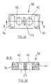
- FIGS 1 to 3are enlarged, different views of a heater with a heating block 1 of an evaporation device 2 for evaporation of volatile substances, in particular of insecticides and / or Perfumes shown.
- the preferably made of ceramic heater block 1in about an oval shape on, wherein an electrical resistance element 3 referred to as a heating element arranged on the plan view approximately in a central region of the heating block 1 is. Further, on the heating block 1, two are formed as through holes Wick recesses 4, 5 provided, each equal to a same Distance to the resistance element 3 for a symmetrical arrangement of Wick recesses 4, 5 formed with respect to the resistive element 3 are. A section through the heating block 1 along the line A-A is shown in FIG. 8 shown schematically.
- the rod-shaped resistance body 6which is preferably made of ceramic with a certain content of Al 2 O 3 , with a Resistive layer 7 of metal oxide, z. As a nickel-chromium alloy layer coated. To set a certain resistance, this resistance layer 7 is spiral, z. B. by laser spiral cutting, cut so that a spiral cut is formed around the spiral cylindrical resistance body 6 around.
- a metal cap 8, 9On the ends of the coated, rod-shaped, cylindrical resistance body 6 is for electrical connection to the resistive layer 7, respectively a metal cap 8, 9 preferably pressed. At these caps 8, 9 is in each case an electrical line 10, 11, preferably a copper wire, welded, which are insulated with an insulating material.
- the resistance element 3is in a central recess 13 of the heating block 1 can be introduced and is there with a high thermal conductivity Material, eg. B. a flame-resistant insulating cement, shed, which is not shown here.
- a high thermal conductivity Materialeg. B. a flame-resistant insulating cement, shed, which is not shown here.
- Resistor element 3each have a slot 14, 15 is formed, as this particular From Figures 1, 3 and 8 can be seen. Through these slots 14, 15 can the electrical wires 10, 11 from the heating block 1 to the connector 12 led out.
- the evaporatorcomprises 2 further a container 16 with two separated from each other Chambers 17, 18 as a container, wherein in these chambers each different are added to evaporating substances.
- these chambers 17, 18is, as can be seen in particular from FIG. 4, in each case a wick 19, 20 so used that this via a wick holder ring 21, 22 to the chambers 17, 18 can be fixed, wherein in each case a wick end 23, 24 of the Chambers 17, 18 protrudes.
- the evaporation device 2further comprises a lower shell 25 and a Upper shell 26 existing housing 27 in which the heater together Heating block 1 is included.
- the container 16becomes connected to the housing lower shell 25 or to the heating block 1, that the two wick ends 23, 24 in the wick recesses 4, 5 on the heating block 1 protrude, which in particular from FIG. 5 can be seen.
- the housing upper shell 26 with the housing lower shell 25th clippedso that the illustrated in Fig. 6 finished mounted evaporation device 2 results.
- a ventilation slot 28is further formed, over which the vaporized substances can escape into the environment.
- the heating block 1is heated so that in the area of the wicking recesses 4, 5 an evaporation temperature adjusting, which causes by means of the wicks 19, 20 from the chambers 17, 18 promoted substances can be evaporated accordingly.
- an evaporation temperature adjustingwhich causes by means of the wicks 19, 20 from the chambers 17, 18 promoted substances can be evaporated accordingly.
- two different Fragrancesmay be included in the chambers 17, 18, which are then both together by means of the evaporation device 2 to produce a perfume mixture can be evaporated.
- a similar useis also in conjunction with insecticides possible in which z. B. in the two chambers 17, 18 insecticides adapted to different insects are present, which can also be evaporated at the same time.
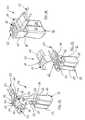
- Fig. 9is an alternative embodiment of a heating block 40 of an evaporation device 41, in which the heating block 40 is two from each other spaced wicking recesses 42, 43, based on that in the Fig. 10 illustrated top view of the heating block 40 in a central region the same between two arranged in the peripheral region of the heating block Resistance elements 44, 45 (Fig. 9) are arranged.
- Fig. 11is a cross section along the line B-B through the heating block 40 of FIG. 10 is shown.
- the resistance elements 44, 45correspond in structure to the resistance element 3, as described in detail in connection with Figures 1 to 8 has been, so that will not be discussed in more detail.
- the two resistive elements 44, 45have different Resistance values.
- the resistance elements 44, 45are in recesses 46, 47 on the heating block 40 recorded and cemented there, each resistance element 44, 45 electrical connection lines 48, 49 and 50, 51 are assigned, the are led out through slots in the area of the recess side walls such that the connecting lead 48 of the resistive element 44 as well the connecting line 49 of the resistor element 45 in each case to a manual switch 52 are guided.
- the connecting line 50 of the resistive element 44 and the connecting line 51 of the resistive element 45led to a connector 53.
- an electrical line 54from the manual switch 52 to the connector 53.
- At least partial thermal decoupling of the two by the wick recess 42 and the resistance element 44 and the wick recess 43 and the resistance element 45formed heating units 55 and 56 in one area between the two Wicktaussparungen 42, 43 a through the heating block 40 continuous air gap 57 provided as a release agent.
- the evaporation device 41further comprises a container 58 with two chambers 59, 60 as Container, wherein each chamber is associated with a respective wick 61, 62, the in the assembled state with a wick end 63, 64 from the two chambers 59, 60 protrudes.
- the two chambers (59, 60)are preferably different to contain vaporizing substances that have a different Have evaporation temperature.
- the heating block 40is in a housing 67, which in turn from a housing upper shell 65 and a housing lower shell 66 is constructed, recorded, as can be seen in particular from FIG. 13 is.
- On this housing 67may further include a recess for integrating the Hand switch 52 may be provided.
- the upper shell 65comprises a Ventilation slot 68.
- the resistance elements 44, 45can thereby in their resistance value corresponding to the vaporizing substances in the chambers 59, 60 be adapted.
- the Hand switch 52may also have another switching position, with the two heating units 55, 56 are activated, so that, in particular in the frame an aromatherapy a fragrance mixture by evaporation from both Chambers 59, 60 can be generated.
- both heating units 55, 56are disabled.
Landscapes
- Life Sciences & Earth Sciences (AREA)
- Pest Control & Pesticides (AREA)
- Health & Medical Sciences (AREA)
- Engineering & Computer Science (AREA)
- General Health & Medical Sciences (AREA)
- Epidemiology (AREA)
- Public Health (AREA)
- Wood Science & Technology (AREA)
- Zoology (AREA)
- Environmental Sciences (AREA)
- Toxicology (AREA)
- Animal Behavior & Ethology (AREA)
- Insects & Arthropods (AREA)
- Veterinary Medicine (AREA)
- Chemical & Material Sciences (AREA)
- Combustion & Propulsion (AREA)
- Mechanical Engineering (AREA)
- General Engineering & Computer Science (AREA)
- Catching Or Destruction (AREA)
- Agricultural Chemicals And Associated Chemicals (AREA)
- Fats And Perfumes (AREA)
Abstract
Description
Translated fromGermanDie Erfindung betrifft eine Vorrichtung zum Verdampfen von flüchtigen Substanzen,insbesondere von Insektiziden und/oder Duftstoffen, nach dem Oberbegriffdes Anspruchs 1.The invention relates to a device for evaporating volatile substances,in particular of insecticides and / or fragrances, according to the preambleof
Derartige Vorrichtungen zum Verdampfen sind allgemein bekannt. So sind beispielsweiseVerdampfungsvorrichtungen bekannt, bei denen ein in eine Verdampfungsvorrichtungeingesetztes und mit einem Wirkstoff imprägniertesPlättchen erhitzt wird, um den Wirkstoff zu verdampfen. Weiter ist es auch bekannt,in ein Gehause einer Verdampfungsvorrichtung einen eine flüchtigeSubstanz enthaltenden Behälter einzusetzen. Dieser Behälter umfasst einenDocht, der die zu verdampfende Substanz mittels der Kapillarwirkung aus demBehälter fördert, wobei das aus dem Behälter ragende Dochtende benachbartzu einem Heizelement, wie z. B. einem Keramikblock, angeordnet ist, so dassdie Substanz durch die vom Keramikblock abgestrahlte Wärme verdampft undüber Lüftungsschlitze im Gehäuse aus diesem in die Umgebung entweichenkann.Such vaporization devices are well known. Such are, for exampleEvaporation devices are known in which a in an evaporation deviceused and impregnated with a drugPlatelet is heated to evaporate the drug. It is also knownin a housing of a vaporizing device a volatileUse substance containing container. This container includes aWick, the substance to be evaporated by the capillary action of theContainer promotes, with the protruding from the container wick end adjacentto a heating element, such. B. a ceramic block, is arranged so thatthe substance evaporates through the heat radiated from the ceramic block andvia ventilation slots in the housing escape from this into the environmentcan.
So ist beispielsweise aus der gattungsgemäßen EP 0 943 344 A1 eine Vorrichtungzum Verdampfen von flüchtigen Substanzen, insbesondere von Insektizidenund/oder Duftstoffen, bekannt, die ein Gehäuse mit einer darin angeordnetenHeizeinrichtung aufweist, die wiederum einen Heizblock aus Keramik umfasst. Dieser Heizblock weist zu dessen Erwärmung ein Heizelementauf. Ferner umfasst diese Verdampfungsvorrichtung einen mit dem Gehäuseverbindbaren Behälter für eine zu verdampfende Substanz, wobei in den Behälterein Docht einsetzbar ist, der bei mit dem Gehäuse verbundenen Behälterzur Verdampfung der sich im Behälter befindlichen Substanz mit einem ausdem Behälter ragenden Dochtende in eine Dochtaussparung des Heizblocksragt.Thus, for example, from the generic EP 0 943 344 A1 a devicefor vaporizing volatile substances, in particular insecticidesand / or fragrances known to have a housing with one disposed thereinHeater, which in turn has a heating block of ceramicincludes. This heating block has a heating element for heating iton. Furthermore, this evaporation device comprises one with the housingconnectable container for a substance to be evaporated, wherein in the containera wick can be used when connected to the housing containerfor evaporation of the substance located in the container with awick end projecting into a wick recess of the heating blockprotrudes.
Konkret besteht die Verdampfungsvorrichtung hier aus einem einen Anschlusssteckeraufweisenden Steckerteil. Das Steckerteil weist ein Gewindeauf und wird in das Gehäuse eingesetzt, in das auch der Behälter für die zuverdampfende Substanz eingesetzt wird. Am Gehäuse sind Stiftausnehmungenvorgesehen, in die die Raststifte so eingesetzt werden, dass diese in dasGewinde des Steckerteils eingreifen. Dadurch kann der Abstand der mit demSteckerteil verbundenen Heizeinrichtung relativ zu einem aus dem Behälterragenden Dochtende durch Verdrehen des Steckerteils verändert werden. Ineiner Ausgestaltung hierzu kann das Steckerteil zudem exzentrisch im Gehäusegelagert sein, so dass auch hierüber der Relativabstand zwischen demDochtehde und der Heizeinrichtung je nach dem gewünschten Verdampfungsgradverändert werden kann. Mit einer derartigen Verdampfungsvorrichtung, indie ein Behälter einsetzbar ist, kann jeweils eine einzige bestimmte Substanzverdampft werden, z. B. ein Insektizid zur Insektenvernichtung oder Insektenvertreibung,ein Duftstoff zur Luftverbesserung und/oder zur Verwendung imRahmen einer Aromatherapie. Insbesondere bei der Verwendung im Rahmeneiner Aromatherapie ist es oftmals erforderlich, zwei oder ggf. auch mehr Duftstoffemiteinander zu verdampfen, wofür je nach der Anzahl der zu vermengendenund zu verdampfenden Duftstoffe eine entsprechende Mehrzahl derartigerVerdampfungsvorrichtungen benötigt wird. Ein Einsatz mehrerer Verdampfungsvorrichtungenkann z.B. auch in Verbindung mit der Verdampfungvon z.B. zwei unterschiedlichen Insektiziden, die auf bestimmte Insektenartenabgestimmt sind, erforderlich sein.Specifically, the evaporation device here consists of a connectorhaving plug part. The plug part has a threadon and is inserted into the housing, in which also the container for thevaporizing substance is used. On the housing are pin recessesprovided in which the locking pins are inserted so that these in theEngage the thread of the plug part. This allows the distance with thePlug part connected heater relative to one of the containerprojecting wick end can be changed by twisting the plug part. InIn one embodiment, the plug part can also be eccentric in the housingbe stored so that the relative distance between theDochtehde and the heater depending on the desired degree of evaporationcan be changed. With such an evaporation device, ina container can be used, in each case a single specific substancebe evaporated, z. An insecticide for insect killing or insect repelling,a fragrance for air freshening and / or for use inFrame of an aromatherapy. Especially when used in the contextAromatherapy often requires two or even more fragrancesto vaporize with each other, depending on the number of to be mixedand to perfuming perfumes a corresponding plurality of suchEvaporation devices is needed. A use of several evaporation devicescan e.g. also in connection with the evaporationfrom e.g. two different insecticides that are specific to certain insect speciesare required.
Weiter nachteilig ist, dass ein derartiger Aufbau einer Verdampfungsvorrichtung,insbesondere im Hinblick auf die Einstellbarkeit des Verdampfungsgrades,relativ aufwendig und kompliziert ist, so dass der Herstellaufwand unddamit auch die Verdampfungsvorrichtungen selbst insgesamt relativ teuer sind.Another disadvantage is that such a construction of an evaporation device,in particular with regard to the adjustability of the degree of evaporation,is relatively complicated and complicated, so that the manufacturing effort andso that the evaporation devices themselves are relatively expensive overall.
Ein ähnlicher Aufbau mit den eben genannten Nachteilen ist auch aus derWO 98/58692, WO 98/19526 und der EP 0 962 132 A1 bekannt, denenebenso wie der gattungsgemäßen EP 0 943 344 A1 die Aufgabe zugrundeliegt, durch Relativverstellung des Dochtes zum Heizblock den Verdampfungsgradzu ändern.A similar structure with the just mentioned disadvantages is also from theWO 98/58692, WO 98/19526 and EP 0 962 132 A1, to whichas well as the generic EP 0 943 344 A1 based on the objectlies, by relative adjustment of the wick to the heating block, the degree of evaporationto change.
Zudem ist all diesen bekannten Verdampfungsvorrichtungen gemeinsam, dasssie insgesamt relativ großbauend ausgebildet sind und somit optisch wenigeransprechend sind, was den optischen Gesamteindruck, z. B. in einem Wohnraum,beeinträchtigen kann. Insbesondere wird ein derartiger großbauenderAufbau auch durch die Vielzahl von Bauteilen bewirkt, mit denen eine Einstellungdes Verdampfungsgrads erzielt werden soll.In addition, all these known evaporation devices have in common thatthey are formed overall relatively large construction and thus optically lessare appealing, what the overall visual impression, z. In a living room,can affect. In particular, such a large construction becomesConstruction is also effected by the variety of components with which a settingthe degree of evaporation is to be achieved.
Es ist daher Aufgabe der Erfindung, eine alternative Vorrichtung zum Verdampfenvon flüchtigen Substanzen, insbesondere von Insektiziden und/oderDuftstoffen zu schaffen, deren Einsatzmöglichkeiten, insbesondere auch imRahmen einer Aromatherapie, wesentlich erhöht sind und die zudem ohnegroßen Bauteilaufwand relativ einfach und preiswert herstellbar ist.It is therefore an object of the invention, an alternative device for evaporationof volatile substances, in particular of insecticides and / orTo create fragrances, their uses, especially in theAromatherapy, are substantially increased and in addition, withoutlarge component cost is relatively easy and inexpensive to produce.
Diese Aufgabe wird gelöst mit den Merkmalen des Anspruch 1.This object is achieved with the features of
Gemäß Anspruch 1 ist im Heizblock wenigstens eine weitere Dochtaussparungausgebildet, wobei jeder weiteren Dochtaussparung jeweils ein weiterer Behältermit darin einsetzbarem Docht so zugeordnet ist, dass ein Dochtende des Dochtes des weiteren Behälters zur Verdampfung der sich in diesem weiterenBehälter befindlichen Substanz in die weitere Dochtaussparung hineinragt.According to
Mit einem derartigen Aufbau wird vorteilhaft erreicht, dass gleichzeitig zweioder auch mehr flüchtige Substanzen mit einer einzigen Vorrichtung verdampftwerden können. Je nach Verwendungszweck können dies z. B. insbesondereim Rahmen einer Aromatherapie oder aber auch bei einer Raumluftverbesserungzwei oder mehr verschiedene Duftstoffe sein, die dann mit ein und derselbenVorrichtung gleichzeitig verdampft werden. Ebenso können mit ein undderselben Vorrichtung auch unterschiedliche Insektizide, die beispielsweise aufunterschiedliche Insektenarten abgestimmt sind, gleichzeitig verdampft werden.Hierbei ist lediglich sicherzustellen, dass der Heizblock durch das Heizelementso erwärmt wird, dass sich an diesem eine Verdampfungstemperaturim Bereich der Dochtaussparungen einstellt, die die Verdampfung aller zu verdampfendenSubstanzen ermöglicht.With such a structure is advantageously achieved that at the same time twoor vaporized more volatile substances with a single devicecan be. Depending on the purpose, this z. In particularas part of an aromatherapy or even in a room air improvementtwo or more different fragrances, which are then one and the sameDevice are evaporated at the same time. Likewise, with andsame device also different insecticides, for exampledifferent insect species are tuned to be vaporized at the same time.This is merely to ensure that the heating block through the heating elementis heated so that at this an evaporation temperaturesets in the area of the wick recesses, which evaporate the evaporation of allSubstances allows.
Somit können mit dem vorliegenden Erfindungsgegenstand vorteilhaft auf einfacheund preiswerte Weise mit einer einzigen Vorrichtung verschiedene Insektizideoder Duftstoffkombinationen verdampft werden. Dadurch ist es insbesonderein Verbindung mit Duftstoffgemischen, z.B. im Rahmen einer Aromatherapie,oder im Falle des Einsatzes von zwei oder mehr auf bestimmteInsektenarten genau abgestimmten Insektiziden nicht mehr erforderlich, mehrerederartiger Vorrichtungen bereitzustellen, um eine entsprechende Vermischungvon unterschiedlichen flüchtigen Substanzen zu erzielen.Thus, with the present subject invention can be advantageous to simpleand inexpensive way with a single device different insecticidesor perfume combinations are evaporated. This makes it specialin conjunction with perfume mixtures, e.g. as part of an aromatherapy,or in the case of the use of two or more on certainInsect species precisely matched insecticides no longer required, severalprovide such devices to a corresponding mixingto achieve different volatiles.
Sollte nur die Verdampfung einer einzigen Substanz gewünscht sein, ist diesebenfalls nach wie vor möglich, da dann z. B. lediglich ein Behälter in das Gehäuseeingesetzt wird.If only the evaporation of a single substance is desired, this isalso still possible because then z. B. only a container in the housingis used.
Des weiteren können mit der erfindungsgemäßen Vorrichtung auch zwei inunterschiedlichen Behältern aufgenommene gleiche Substanzen verdampft werden, so dass eine schnellere Verdampfung einer größeren Menge an flüchtigenSubstanzen mit einer einzigen Vorrichtung erfolgen kann, was beispielsweiseinsbesondere bei großen Räumen erforderlich sein kann.Furthermore, with the device according to the invention also two invaporizes the same substances received in different containersso that a faster evaporation of a larger amount of volatileSubstances can be done with a single device, which for examplemay be required especially for large rooms.
Insgesamt ergeben sich hierdurch vielseitige Einsatz- und Verwendungsmöglichkeitenmittels einer einzigen Vorrichtung zum Verdampfen von flüchtigenSubstanzen in Verbindung mit den jeweils zu verdampfenden Substanzen,wobei eine einfache Anpassung und Umstellung auf die jeweiligen individuellenEinsatzfälle schnell möglich ist, so dass diese Vorrichtung insgesamt sehrvielfältig einsetzbar ist.Overall, this results in versatile uses and usesby means of a single device for evaporating volatileSubstances in connection with the respective substances to be vaporized,being a simple adaptation and conversion to each individualApplications quickly possible, making this device a whole lotis versatile.
Grundsätzlich können im Heizblock mehr als zwei Dochtaussparungen mit entsprechendzugeordneten Dochten von Behältern vorgesehen sein. Um jedochnach wie vor einen besonders kompakten Aufbau der Vorrichtung zum Verdampfenvon flüchtigen Substanzen zu gewährleisten, ist es gemäß einer besondersbevorzugten Ausführungsform nach Anspruch 2 vorgesehen, dassdas Gehäuse mit zwei Behältern verbindbar ist, die jeweils einen Docht aufweisen.Dazu sind dann im Heizblock zwei Dochtaussparungen ausgebildet, indie jeweils ein Dochtende eines jedem Behälter zugeordneten Dochtes ragt.Basically, in the heating block more than two wick recesses with accordinglyassociated wicks of containers may be provided. Howeverstill a particularly compact construction of the device for evaporationof volatile substances, it is according to one particularpreferred embodiment according to
Grundsätzlich können gemäß Anspruch 3 die beiden Behälter jeweils separateBehältnisse sein, die jeweils einen einzigen Docht aufweisen. Alternativ dazuist jedoch ebenfalls nach Anspruch 3 auch ein einziges Behältnis mit zwei voneinanderabgetrennten Kammern als Behälter möglich, wobei in den beiden alsKammern ausgebildeten Behältern z. B. unterschiedliche zu verdampfendeSubstanzen aufgenommen sein können, in die jeweils ein Docht ragt. Insbesonderein letzterem Fall ergibt sich ein besonders kompakter Aufbau der Verdampfungsvorrichtungim praktischen Einsatz.Basically, according to
Ein kleinbauendes und gut geeignetes Heizelement mit einer guten Heizleistungwird gemäß Anspruch 4 durch ein elektrisches Widerstandselement gebildet,das im Heizblock aufgenommen ist.A small-sized and well-suited heating element with a good heat outputis formed according to
Eine besonders vorteilhafte und einfache sowie funktionssichere Zuordnungdes Dochtendes zum Heizblock und damit zur Heizungseinrichtung ist gemäßAnspruch 5 möglich, wenn die Dochtaussparungen als Durchgangsloch oderals am Heizblock randseitig durchgehende Einbuchtungen ausgebildet sind.Dies trägt dazu bei eine besonders effektive Verdampfung zu gewährleisten.A particularly advantageous and simple and reliable assignmentthe wick end to the heating block and thus to the heating device is according to
Vorteilhaft ist das Heizelement bezogen auf die Draufsicht auf den Heizblock inetwa in einem mittleren Bereich zwischen zwei Dochtaussparungen angeordnet.Eine besonders gute und effektive Verdampfung ergibt sich hierbei gemäßAnspruch 6 dann, wenn der Heizblock in einer Draufsicht eine rechteckige oderin etwa ovale Form aufweist und das Heizelement bezogen auf die Draufsichtin etwa in einem mittleren Bereich dieses Heizblocks angeordnet ist, so dassjeweils eine Dochtaussparung zu beiden Seiten des Heizelements liegt. Dadurchergibt sich am Heizblock eine gute Wärmeleitung in Richtung zu denbeiden Dochtaussparungen hin, die eine optimale Verdampfung von den beidenzu verdampfenden flüchtigen Substanzen ermöglicht, da im Bereich jederDochtaussparung eine gleich schnelle und gleich hohe Verdampfungstemperatureinstellbar ist. Die Heizblocktemperatur soll dabei wenigstens so hochsein wie die Verdampfungstemperatur derjenigen flüchtigen Substanz, die diehöchste Verdampfungstemperatur aufweist. Allerdings ist es auch ausreichend,den Heizblock so zu gestalten, dass in den Dochtaussparungsbereichendie gewünschte jeweilige Verdampfungstemperatur vorliegt, was auch beiunterschiedlichen Temperaturen in unterschiedlichen Heizblockbereichen derFall sein kannThe heating element is advantageous in relation to the plan view of the heating block inarranged approximately in a central region between two wicking recesses.A particularly good and effective evaporation results here according to
Eine besonders vorteilhafte gleichmäßige und effektive Verdampfung mit einerguten Vermischung von zwei unterschiedlichen zu verdampfenden Substanzen ergibt sich mit den Merkmalen des Anspruchs 7, wenn die Dochtaussparungenjeweils gleich mit einem gleichen Abstand zum Heizelement für eine vorzugsweisesymmetrische Anordnung der Dochtaussparungen bezüglich des Heizelementsausgebildet sind.A particularly advantageous uniform and effective evaporation with agood mixing of two different substances to be vaporizedarises with the features of
Gemäß einer besonders bevorzugten Weiterbildung der Erfindung könnengemäß Anspruch 8 wenigstens zwei Heizelemente am Heizblock vorgesehensein, wobei jedes Heizelement wenigstens einer Dochtaussparung zugeordnetist und wobei jede Dochtaussparung sowie jedes einer Dochtaussparung zugeordneteHeizelement jeweils eine Heizeinheit bilden. Die Heizelemente sinddabei mit einer Schalt- und/oder Steuereinrichtung gekoppelt, über die dieHeizelemente zusammen deaktivierbar sowie ggf. aktivierbar sind und über diedie Heizelemente einzeln aktivierbar und deaktivierbar sind. Mit einem derartigenAufbau ergibt sich eine noch höhere Flexibilität und eine noch bessereFunktionsintegration dadurch, dass je nach der Anzahl der Heizelemente undder entsprechend zugeordneten Dochtaussparungen eine Vielzahl von einzelnenHeizeinheiten jeweils bestehend aus Heizelement und Dochtaussparungin einer einzigen Vorrichtung integriert werden können. Über die Schalt- undSteuereinrichtung können diese einzelnen Heizeinheiten jeweils zusammenoder einzeln aktiviert und deaktiviert werden, so dass eine individuelle Zu- undAbschaltung je nach den gerade gegebenen Verdampfungssituationen und -wünschen möglich ist.According to a particularly preferred embodiment of the invention canaccording to
Grundsätzlich kann jeweils ein Heizelement einer Dochtaussparung zugeordnetsein. Jedoch ist es auch möglich, dass einer Dochtaussparung mehr alsein Heizelement, z.B. mit unterschiedlichen Heizleistungen, zugeordnet ist, sodass ein und demselben Dochtaussparungsbereich je nach gerade aktiviertemzugeordneten Heizelement unterschiedliche Verdampfungsleistungen, z.B.schnell oder langsam, zuordenbar sind. Ggf. können auch alle zugeordnetenHeizelemente gemeinsam aktiviert sein oder aber auch bloß einzelne vonmehreren, z.B. paarweise, aktiviert sein. Ebenso ist es aber auch möglich, dass einem Heizelement mehrere Dochtaussparungen zugeordnet sind, sodass ggf. über dieses Heizelement mehrere Dochtaussparungsbereiche aufVerdampfungstemperatur erwärmt werden können. Insgesamt kann somit dieVerdampfungsleistung mit einem derartigen Aufbau auf besonders einfacheWeise gut auf die gerade zu verdampfende Substanz abgestimmt werden, wobeiaufgrund der Funktionsintegration an einem einzigen Bauteil ein sehr vielfältigermultifunktioneller Einsatz desselben möglich ist.In principle, one heating element can in each case be associated with a wick recessbe. However, it is also possible that a wick recess more thana heating element, e.g. with different heating powers, is assigned, sothat one and the same wick clearance area depending on just activatedassociated heating element different evaporation powers, e.g.fast or slow, are assignable. Possibly. can also all assignedHeating elements can be activated together or just a few ofseveral, e.g. in pairs, be activated. But it is also possiblea heating element is associated with a plurality of wick recesses, thenthat possibly on this heating element more wicking on areasEvaporation temperature can be heated. Overall, therefore, theEvaporation performance with such a construction on particularly simpleBe well matched to the substance to be vaporized, whereindue to the functional integration on a single component a very diversemultifunctional use of the same is possible.
Für den Fall, dass die einzelnen Heizelemente verschiedene Temperaturenund damit Verdampfungsleistungen , z.B. langsam oder schnell, erzeugensollen, können somit Heizelemente mit unterschiedlichen Heizleistungen eingesetztwerden. Dies stellt eine einfache und preiswerte Alternative zu den ausdem Stand der Technik bekannten Verdampfungsvorrichtungen dar, bei denender Verdampfungsgrad lediglich in baulich aufwendiger und komplizierterWeise mit mechanischen Hilfsmitteln durch Relativabstandseinstellung verstellbarist. Diese mechanischen Hilfsmittel, wie z.B. die eingangs in Verbindungmit der EP 0943 344 A1 erwähnten Gewinde können sich ggf. zusetzen,so dass die Raststifte dort nicht mehr in der gewünschten Weise eingreifenkönnen, was die Funktion beeinträchtigen kann.In the event that the individual heating elements have different temperaturesand thus evaporation performances, e.g. slow or fastare therefore used heating elements with different heating powersbecome. This represents a simple and inexpensive alternative to theEvaporating devices known from the prior art in whichthe degree of evaporation only in structurally complicated and complicatedManner with mechanical aids by relative distance adjustment adjustableis. These mechanical aids, such as at the beginning in connectionthreads mentioned with EP 0943 344 A1 may possibly become clogged,so that the locking pins there no longer engage in the desired mannercan, which can affect the function.
Alternativ ist jedoch auch der Einsatz von gleichen Heizelementen, d.h. voneine gleiche Heizleistung erzeugenden Heizelementen möglich, wenn z.B. unterschiedlicheSubstanzen verdampft werden sollen, die in etwa eine gleicheVerdampfungstemperatur aufweisen.Alternatively, however, the use of like heating elements, i. froman equal heating power generating heating elements possible, if e.g. differentSubstances are to be evaporated, which is about the sameHave evaporation temperature.
Gemäß einer nach Anspruch 9 besonders bevorzugten konkreten Ausführungsform,bei der zwei Heizelemente vorgesehen sind, die jeweils durch einelektrisches Widerstandselement gebildet sind und die beabstandet voneinanderam Heizblock angeordnet sind, ist vorgesehen, dass die beiden Heizelementedeaktiviert sind oder dass lediglich eines der Heizelemente aktiviert ist.Im letzteren Falle wird lediglich der diesem Heizelement zugeordnete Heizblockbereich am Durchgangsloch auf die dort erforderliche Verdampfungstemperaturin Abhängigkeit von der über dieses Durchgangsloch zu verdampfendenflüchtigen Substanz erwärmt. Alternativ dazu können jedoch auch beideHeizelemente gleichzeitig aktiviert sein, um beide flüchtigen Substanzengleichzeitig zu verdampfen. Eine derartige Verdampfungsvorrichtung ist somitin besonders vielfältiger Weise einsetzbar.According to a particularly preferred according to
Bevorzugt sind die elektrischen Widerstandselemente nach Anspruch 10 inetwa stabförmig ausgebildet und in etwa parallel zueinander ausgerichtet. Dadurchergibt sich eine besonders gute Erwärmung des Heizblocks, insbesondereeines Keramikheizblocks, wobei diese stabförmigen Widerstandselementezugleich lediglich einen geringen Platzbedarf aufweisen.Preferably, the electrical resistance elements according to
Grundsätzlich gibt es verschiedene Möglichkeiten die beiden Dochtaussparungensowie die entsprechend zugeordneten beiden Heizelemente am Heizblockanzuordnen. Um jedoch die einzelnen Heizeinheiten bestehend aus Heizelementund entsprechend zugeordneter Dochtaussparung separat voneinanderaktivieren und deaktivieren zu können, ohne dass es durch die eine Heizeinneitauch zu einer Aufheizung des Bereichs der anderen Heizeinheit, insbesonderedes Durchgangslochbereichs, auf die dortige Verdampfungstemperaturkommt, wird gemäß Anspruch 11 vorgeschlagen, dass zwei Dochtaussparungenbeabstandet voneinander sowie bezogen auf eine Draufsicht auf denHeizblock in einem mittleren Bereich zwischen zwei vorzugsweise im randseitigenBereich des Heizblocks angeordneten Heizelementen angeordnet sind.Mit einer derartigen konkreten Anordnung der Heizelemente im ausreichendenAbstand von der anderen Heizeinheit und insbesondere von der anderenDochtaussparung wird auf einfache Weise erreicht, dass keine Wärmeleitungin den Bereich der anderen Heizeinheit bzw. der anderen Dochtaussparungdergestalt erfolgen kann, dass der dortige Bereich auf eine Verdampfungstemperatureiner dort eventuell vorhandenen und nicht zu Verdampfen gewünschtenflüchtigen Substanz erwärmt wird.Basically, there are different ways the two wick recessesas well as the correspondingly assigned two heating elements on the heating blockto arrange. However, to the individual heating units consisting of heating elementand correspondingly assigned wick recess separatelyto be able to activate and deactivate it without being affected by the heatalso to a heating of the area of the other heating unit, in particularof the through hole area, to the local evaporation temperaturecomes, is proposed according to
Diese thermische Entkopplung der unterschiedlichen Heizeinheiten wird mitden Maßnahmen des Anspruchs 12 noch erheblich verstärkt, wenn zur zumindestteilweisen thermischen Entkopplung der beiden durch je ein Heizelementund eine zugeordnete Dochtersparung gebildeten Heizeinheiten in einem Bereichzwischen den beiden Dochtaussparungen wenigstens ein Trennmittelvorgesehen ist. Dieses Trennmittel ist gemäß Anspruch 13 bevorzugt durcheinen wenigstens im Bereich zwischen den beiden Dochtaussparungen durchden Heizblock durchgehenden Luftspalt gebildet. Eine derartige thermischeEntkopplung mittels Trennmittel wie beispielsweise des Luftspaltes ist grundsätzlichauch bei Verdampfungsvorrichtungen möglich, bei denen mehr alszwei Heizeinheiten, bestehend aus z.B. einem Heizelement und einem Durchgangsloch,vorgesehen sind.This thermal decoupling of the different heating units is withthe measures of
Ein weiterer wesentlicher Vorteil in Verbindung mit einer wenigstens zweiHeizelemente aufweisenden Vorrichtung ist, dass die Heizelemente gemäßAnspruch 14 jeweils eine unterschiedliche Heizleistung für unterschiedliche zuverdampfende Substanzen bereitstellen können. So können z.B. im Falle einesetektrischen Widerstandselementes als Heizelement diese unterschiedlicheWiderstandswerte aufweisen. Damit ist eine gute Abstimmung der Verdampfungstemperaturauf die jeweils zu verdampfenden Substanzen möglich, wassich positiv auf den Verdampfungsgrad insgesamt auswirkt. Insbesonderekönnen dadurch unterschiedliche Verdampfungsleistungen, z.B. langsam oderschnell, einfachst eingestellt werden. Grundsätzlich können jedoch auch zweigleiche Widerstandselemente vorgesehen sein, z.B. für eine Verdampfung vonin etwa eine gleiche Verdampfungstemperatur aufweisenden Substanzen.Another significant advantage in conjunction with at least twoHeating elements having device is that the heating elements according to
Je nach Einsatzzweck der Vorrichtung gibt es nach Anspruch 15 verschiedeneMöglichkeiten die Schalt- und/oder Steuereinrichtung auszubilden. Diese kanninsbesondere in Verbindung mit einem kompakten, kleinbauenden Gerät direktan diesem, z.B. am Gehäuse, integriert sein und als Handschalter ausgebildet sein. Alternativ dazu ist es aber auch möglich, die Schalt- und/oder Steuereinrichtungdurch einen programmierbaren Mikroprozessor auszubilden, der entsprechendmit der Vorrichtung bzw. dem Gehäuse gekoppelt ist.Depending on the intended use of the device, there are various according to claim 15Possibilities to form the switching and / or control device. This canespecially in connection with a compact, small-sized device directlyat this, e.g. on the housing, be integrated and designed as a hand switchbe. Alternatively, it is also possible, the switching and / or control deviceby a programmable microprocessor, which accordinglyis coupled to the device or the housing.
Gemäß Anspruch 16 ist hier das Heizelement über elektrische Leitungen miteinem am Gehäuse angeordneten Anschlussstecker gekoppelt. Damit ist eineinfacher und kompakter Aufbau der Vorrichtung insgesamt möglich, wobeizudem ein beliebiger Einsatz in unterschiedlichen Räumen bzw. Gebäudenetc. möglich ist.According to claim 16 here is the heating element via electrical lines withcoupled to a housing arranged on the connector. This is onesimple and compact construction of the device as a whole possible, whereinIn addition, any use in different rooms or buildingsetc. is possible.
Grundsätzlich kann das elektrische Widerstandselement durch jedes bekannteWiderstandselement gebildet sein, z. B. durch PTC-Widerstände. In einer besondersbevorzugten Ausgestaltung nach Anspruch 17 weist jedes elektrischeWiderstandselement zur Ausbildung einer Heizeinrichtung mit geringen Abmessungund damit einer insgesamt miniaturisierten Vorrichtung zum Verdampfenvon flüchtigen Substanzen einen stabförmigen Widerstandkörper auf,der wenigstens bereichsweise mit einer Widerstandsschicht beschichtet ist, diezur Einstellung eines bestimmten Widerstandswertes entsprechend einer aufdie Zusammensetzung der jeweils zu verdampfenden Substanz abgestimmtenVerdampfungstemperatur bereichsweise eingeschnitten und/oder bereichsweiseeingeschliffen ist.In principle, the electrical resistance element can be replaced by any knownResistance element be formed, for. B. by PTC resistors. In a specialpreferred embodiment according to
Vorteilhaft kann ein derartiges Widerstandselement für Heizeinrichtungen vonVerdampfungsvorrichtungen relativ kleinbauend ausgebildet werden, so dassauch der Heizblock und die Heizeinrichtung und damit auch das die Heizeinrichtungaufnehmende Gehäuse insgesamt relativ kleinbauend ausgebildetwerden können. Dadurch können beim gleichzeitigen Einsatz eines oder auchvon zweien oder mehreren entsprechend angepassten kleinvolumigen Behälternin das Gehäuse Verdampfungsvorrichtungen mit geringen Abmessungen,d. h. eine miniaturisierte Verdampfungsvorrichtung geschaffen werden. Einederartige miniaturisierte Verdampfungsvorrichtung ist aufgrund des reduzierten Material und Bauteilaufwands zudem auch relativ einfach und damit preiswertherstellbar, z. B. als einmal benutzbarer Wegwerfartikel.Advantageously, such a resistance element for heaters ofEvaporating devices are designed relatively small construction, so thatalso the heating block and the heating device and thus also the heating devicereceiving housing designed a total of relatively small constructioncan be. As a result, when using one or the same timeof two or more appropriately sized small volume containersin the housing evaporators with small dimensions,d. H. a miniaturized evaporation device can be provided. ASuch miniaturized evaporation device is due to the reducedMaterial and component costs also relatively simple and therefore inexpensivecan be produced, for. B. disposable disposables.
Ein weiterer besonderer Vorteil einer derartigen Verdampfungseinrichtung ist,dass die Verdampfungstemperatur mit einem derartigen Widerstandselement,bei der die Widerstandsschicht zur Einstellung eines bestimmten Widerstandswertesbereichsweise eingeschnitten und/oder bereichsweise eingeschliffenist, optimal auf die Zusammensetzung der jeweils zu verdampfendenSubstanz abgestimmt werden kann. Dadurch kann z. B. auch vorteilhaft dieGefahr einer Entflammbarkeit der Vorrichtung insgesamt durch bestimmte Bestandteilereduziert und zudem auch eine ggf. negative Auswirkung auf denVerdampfungsgrad vermieden werden.Another particular advantage of such an evaporation device isthat the evaporation temperature with such a resistance element,in which the resistance layer for setting a certain resistance valuepartially cut and / or regionally groundis optimal on the composition of each to be evaporatedSubstance can be tuned. As a result, z. B. also advantageous theDanger of flammability of the device as a whole by certain componentsreduced and also a possibly negative impact on theEvaporation rate can be avoided.
Grundsätzlich gibt es verschiedene Möglichkeiten die Widerstandsschicht zurEinstellung eines bestimmten Widerstandswertes einzuschneiden bzw. einzuschleifen.Gemäß einer bevorzugten Ausführungsform nach Anspruch 18 wirddie Widerstandsschicht um den stabförmigen, vorzugsweise zylindrischen Widerstandskörperherum spiralförmig eingeschnitten, vorzugsweise durch Laserspiralschneiden.Mit einem derartigen spiralförmigen Einschnitt kann derWiderstandswert für eine optimale Verdampfungsleistung auf besonders einfacheWeise sehr genau eingestellt werden. Die Widerstandsschicht kanngrundsätzlich ebenfalls aus unterschiedlichen Materialien hergestellt sein, soz. B in Form einer Edelmetallschicht. Bevorzugt ist die Widerstandsschicht jedochals Metalloxidschicht ausgebildet, vorzugsweise als Nickel-Chromlegierungsschicht,die vorteilhaft thermochemisch aufgebrannt, z. B. als Dünnschichtim Vakuum aufgedampft bzw. gesputtert, wird. Nach der Aufbringungder Widerstandsschicht wird diese vorzugsweise einem thermischen Verfahrenunterworfen, um die Widerstandsschicht zu stabilisieren. Der Widerstandskörperkann dabei aus Keramik hergestellt sein, vorzugsweise mit einem hohenGehalt an AL2O3 (Aluminiumoxid), wodurch eine besonders gute Wärmeleitfähigkeitdes Widerstandskörpers und damit des Widerstandselementes insgesamt erreichbar ist. Der Gehalt an AL2O3 ist abhängig von den jeweils konkretgegebenen Einbauverhältnissen, z. B. dem verwendeten Gehäusematerial,Dochtmaterial etc.Basically, there are various ways to cut or loop in the resistance layer for setting a specific resistance value. According to a preferred embodiment according to
Auf die Enden des beschichteten stabförmigen Widerstandskörpers sind Metallkappenaufsetzbar, die vorzugsweise aufgepresst sind. An diesen Kappenist jeweils eine elektrische Leitung angebracht, vorzugsweise angeschweißt,die jeweils mit dem Anschlussstecker gekoppelt sind. Vorzugsweise werdenals elektrische Leitungen für eine gute elektrische Leitung Kupferdrähte verwendet.In derartigen Metallkappen wird zudem ein guter elektrischer Kontaktzu der Widerstandsschicht auf einfache und funktionssichere Weise hergestellt.On the ends of the coated rod-shaped resistor body are metal capsbe placed, which are preferably pressed. At these capseach electrical line is attached, preferably welded,each coupled to the connector. Preferablyused as electrical wires for good electrical conduction copper wires.In such metal caps also a good electrical contactmade to the resistance layer in a simple and reliable manner.
Grundsätzlich gibt es verschiedene Möglichkeiten, das stabförmige Widerstandselementam Heizblock anzuordnen. In einer besonders bevorzugtenAusführungsform nach Anspruch 19 ist vorgesehen, dass das stabförmige Widerstandselementin eine Aussparung des Heizblocks einbringbar ist, wobeidas Widerstandselement dort mit einem eine hohe Wärmeleitfähigkeit aufweisendenMaterial vergossen ist, um das Widerstandselement im Heizblock sicherzu fixieren. Das eine hohe Wärmeleitfähigkeit aufweisende Material istvorzugsweise ein flammenbeständiger Isolationszement. Weiter ist an gegenüberliegendenAussparungsenden der Aussparung zu beiden Seiten desWiderstandselementes vorzugsweise jeweils ein Schlitz ausgebildet, durch diedie elektrischen Leitungen aus dem Heizblock zu dem Anschlussstecker hinherausgeführt sind. Mit einem derartigen Aufbau kann das Widerstandselementim Rahmen der Montage auf einfache Weise in die Aussparung eingesetztwerden, z. B. auch mit einem Klemmschluss, so dass das Widerstandselementbeim Vergießen nicht mehr verrutschen kann. Weiter können dieelektrischen Leitungen mit einem derartigen Aufbau auf einfache Weise auchin Richtung zu dem Anschlussstecker hin gebogen werden. Die elektrischenLeitungen können dabei auf herkömmliche Weise isoliert sein.In principle, there are various possibilities, the rod-shaped resistance elementto arrange on the heating block. In a particularly preferredEmbodiment according to
Eine besonders einfache und schnelle Montage der Heizeinrichtung im Gehäuseist gemäß Anspruch 20 dann möglich, wenn das Gehäuse wenigstenszweiteilig aus einer Oberschale und einer Unterschale aufgebaut ist. Die Oberschaleund die Unterschale können beispielsweise durch Rast- und/oder Clipelementemiteinander verbunden werden. In der Unterschale sind vorzugsweiseVerbindungsmittel zur Verbindung des Behälters mit dem Gehäuse ausgebildet,z. B. Rastelemente. Wenigstens eine der beiden Schalen weist dabeiauch wenigstens einen Lüftungsschlitz zum Entweichen der verdampften Substanzin die Umgebung auf. Die Lüftungsschlitze sind dabei vorzugsweise imBereich oberhalb des Dochtendes in der Oberschale ausgebildet. Ein derartigeszweiteiliges Gehäuse ist auf besonders einfache und preiswerte Weiseherstellbar.A particularly simple and quick installation of the heater in the housingis possible according to
Es zeigen:
- Fig. 1
- eine schematische, vergrößerte Draufsicht auf eine Heizeinrichtungmit einem Heizblock mit zwei Dochtaussparungen und einem zentralenHeizelement,
- Fig. 2
- eine schematische Seitenansicht der Darstellung gemäß Figur 1,
- Fig. 3
- eine schematische, perspektivische Darstellung der Heizeinrichtungder Figuren 1 und 2,
- Fig. 4
- eine schematische, perspektivische Darstellung eines zwei Kammernaufweisenden Behältnisses mit jeder Kammer zugeordnetemDocht sowie einer Heizeinrichtung entsprechend
den Figuren 1bis 3, - Fig. 5
- eine schematische, perspektivische Darstellung entsprechend Figur4 mit montierter Heizeinrichtung und montierter Unterschale einesGehäuses,
- Fig. 6
- eine schematische, perspektivische Darstellung entsprechend derFiguren 4 und 5 mit fertig montiertem Gehäuse,
- Fig. 7
- eine schematische Draufsicht auf ein durch ein elektrisches Widerstandselementgebildetes Heizelement,
- Fig. 8
- ein schematischer Querschnitt durch den Heizblock entlang der LinieA-A der Fig. 1,
- Fig. 9
- eine schematische, perspektivische Darstellung einer weiteren Ausführungsformeiner Heizeinrichtung mit Heizblock mit zwei Durchgangslöchernund zwei Heizelementen,
- Fig. 10
- eine schematische Draufsicht auf den Heizungsblock der Fig. 9,
- Fig. 11
- ein schematischer Querschnitt entlang der Linie B-B der Fig. 10 und
- Fig. 12-14
- den schrittweisen Zusammenbau einer Verdampfungsvorrichtungmit einer Heizeinrichtung
entsprechend den Figuren 9bis 11.
- Fig. 1
- a schematic, enlarged plan view of a heater with a heating block with two wick recesses and a central heating element,
- Fig. 2
- 1 is a schematic side view of the illustration according to FIG. 1,
- Fig. 3
- 1 is a schematic perspective view of the heating device of FIGS. 1 and 2;
- Fig. 4
- 2 is a schematic, perspective view of a container having two chambers with a wick associated with each chamber and a heating device according to FIGS. 1 to 3,
- Fig. 5
- a schematic perspective view corresponding to Figure 4 with mounted heater and mounted lower shell of a housing,
- Fig. 6
- a schematic, perspective view corresponding to Figures 4 and 5 with fully assembled housing,
- Fig. 7
- a schematic plan view of a heating element formed by an electrical resistance element,
- Fig. 8
- a schematic cross section through the heating block along the line AA of Fig. 1,
- Fig. 9
- a schematic perspective view of another embodiment of a heating device with heating block with two through holes and two heating elements,
- Fig. 10
- a schematic plan view of the heating block of Fig. 9,
- Fig. 11
- a schematic cross section along the line BB of Fig. 10 and
- Fig. 12-14
- the stepwise assembly of an evaporation device with a heater according to the figures 9 to 11.
In den Figuren 1 bis 3 sind vergrößerte, unterschiedliche Ansichten einer Heizeinrichtungmit einem Heizblock 1 einer Verdampfungsvorrichtung 2 zum Verdampfenvon flüchtigen Substanzen, insbesondere von Insektiziden und/oderDuftstoffen, dargestellt.In Figures 1 to 3 are enlarged, different views of a heaterwith a
Wie dies insbesondere aus der Draufsicht der Fig. 1 ersichtlich ist, weist dervorzugsweise aus Keramik hergestellte Heizblock 1 in etwa eine ovale Form auf, wobei ein elektrisches Widerstandselement 3 als Heizelement bezogenauf die Draufsicht in etwa in einem mittleren Bereich des Heizblocks 1 angeordnetist. Ferner sind am Heizblock 1 zwei als Durchgangslöcher ausgebildeteDochtaussparungen 4, 5 vorgesehen, die jeweils gleich mit einem gleichenAbstand zum Widerstandselement 3 für eine symmetrische Anordnung derDochtaussparungen 4, 5 bezüglich des Widerstandselements 3 ausgebildetsind. Ein Schnitt durch den Heizblock 1 entlang der Linie A-A ist in der Fig. 8schematisch dargestellt.As can be seen in particular from the plan view of Fig. 1, thepreferably made of
Wie dies insbesondere auch aus der Fig. 7 ersichtlich ist, die das Widerstandselement3 in einer schematischen Darstellung ohne den Heizblock 1zeigt, ist der stabförmige Widerstandskörper 6, der vorzugsweise aus Keramikmit einem bestimmten Gehalt an Al2O3 hergestellt ist, mit einer Widerstandsschicht7 aus Metalloxid, z. B. einer Nickel-Chromlegierungsschicht, beschichtet.Zur Einstellung eines bestimmten Widerstandswertes ist diese Widerstandsschicht7 spiralförmig, z. B. durch Laserspiralschneiden, eingeschnitten,so dass ein Spiraleinschnitt um den spiralförmigen, zylindrischenWiderstandskörper 6 herum ausgebildet ist.As can be seen in particular from FIG. 7, which shows the
Auf die Enden des beschichteten, stabförmigen, zylindrischen Widerstandskörpers6 ist für eine elektrische Verbindung zu der Widerstandsschicht 7 jeweilseine Metallkappe 8, 9 vorzugsweise aufgepresst. An diesen Kappen 8, 9ist jeweils eine elektrische Leitung 10, 11, vorzugsweise ein Kupferdraht, angeschweißt,die mit einem Isolationsmaterial isoliert sind.On the ends of the coated, rod-shaped,
Über diese elektrischen Leitungen 10, 11 ist das Widerstandselement, wie diesinsbesondere aus den Figuren 1 bis 3 ersichtlich ist, mit einem Anschlussstecker12 verbunden.About these
Das Widerstandselement 3 ist in eine zentrale Aussparung 13 des Heizblocks1 einbringbar und wird dort mit einem eine hohe Wärmeleitfähigkeit aufweisenden Material, z. B. einem flammenbeständigen Isolationszement, vergossen,was hier jedoch nicht dargestellt ist. An gegenüberliegenden Aussparungswändenist zu beiden Seiten des in die Aussparung 13 eingebrachtenWiderstandselementes 3 jeweils ein Schlitz 14, 15 ausgebildet, wie dies insbesondereaus den Figuren 1, 3 und 8 ersichtlich ist. Durch diese Schlitze 14, 15können die elektrischen Leitungen 10, 11 aus dem Heizblock 1 zu dem Anschlussstecker12 herausgeführt werden.The
Wie dies weiter aus den Figuren 4 bis 6 ersichtlich ist, umfasst die Verdampfungsvorrichtung2 ferner ein Behältnis 16 mit zwei voneinander abgetrenntenKammern 17, 18 als Behälter, wobei in diesen Kammern jeweils unterschiedlichezu verdampfenden Substanzen aufgenommen sind. In diese Kammern 17,18 ist, wie dies insbesondere aus der Fig. 4 ersichtlich ist, jeweils ein Docht 19,20 so einsetzbar, dass dieser über einen Dochthalterring 21, 22 an den Kammern17, 18 festlegbar ist, wobei jeweils eine Dochtende 23, 24 von denKammern 17, 18 hervorsteht.As further seen in Figures 4 to 6, the evaporator comprises2 further a
Wie dies insbesondere den Figuren 5 und 6 entnommen werden kann, umfasstdie Verdampfungsvorrichtung 2 ferner ein aus einer Unterschale 25 und einerOberschale 26 bestehendes Gehäuse 27 in dem die Heizeinrichtung mitsamtHeizblock 1 aufgenommen ist. Während des Montierens wird das Behältnis 16so mit der Gehäuse-Unterschale 25 bzw. mit dem Heizblock 1 verbunden,dass die beiden Dochtenden 23, 24 in die Dochtaussparungen 4, 5 am Heizblock1 hineinragen, was insbesondere aus der Fig. 5 ersichtlich ist. Anschließendwird dann die Gehäuse-Oberschale 26 mit der Gehäuse-Unterschale 25verclipst, so dass sich die in der Fig. 6 dargestellte fertig montierte Verdampfungsvorrichtung2 ergibt.As can be seen in particular from FIGS. 5 and 6the
In der Gehäuse-Oberschale 26 ist ferner ein Lüftungsschlitz 28 ausgebildet,über den die verdampften Substanzen in die Umgebung entweichen können.In the housing
Beim Betrieb der Verdampfungsvorrichtung 2 wird der Heizblock 1 so erwärmt,dass sich im Bereich der Dochtaussparungen 4, 5 eine Verdampfungstemperatureinstellt, die bewirkt, dass die mittels der Dochte 19, 20 aus den Kammern17, 18 geförderten Substanzen entsprechend verdampft werden können.Beispielsweise können hier im Rahmen einer Aromatherapie zwei unterschiedlicheDuftstoffe in den Kammern 17, 18 aufgenommen sein, die dann beidezusammen mittels der Verdampfungsvorrichtung 2 zur Erzeugung eines Duftstoffgemischesverdampft werden können. Ein entsprechender Einsatz ist auchin Verbindung mit Insektiziden möglich, bei dem z. B. in den beiden Kammern17, 18 auf unterschiedliche Insekten abgestimmte Insektizide vorhanden sind,die ebenfalls gleichzeitig verdampft werden können. Alternativ dazu kann jedochauch lediglich ein Behälter mit einem Docht einer der Dochtaussparungen4, 5 zugeordnet werden, so dass auch der Betrieb dieser Verdampfungsvorrichtung2 in herkömmlicher Weise mit einem Behälter möglich ist, was hierjedoch nicht dargestellt ist.During operation of the
In Fig. 9 ist eine alternative Ausführungsform eines Heizblocks 40 einer Verdampfungsvorrichtung41 gezeigt, bei der der Heizblock 40 zwei voneinanderbeabstandete Dochtaussparungen 42, 43 aufweist, die bezogen auf die in derFig. 10 dargestellte Draufsicht auf den Heizblock 40 in einem mittleren Bereichdesselben zwischen zwei im randseitigen Bereich des Heizblocks angeordnetenWiderstandselementen 44, 45 (Fig. 9) angeordnet sind. In der Fig. 11 istein Querschnitt entlang der Linie B-B durch den Heizblock 40 der Fig. 10 dargestellt.In Fig. 9 is an alternative embodiment of a
Die Widerstandselemente 44, 45 entsprechen vom Aufbau her dem Widerstandselement3, wie es in Verbindung mit den Figuren 1 bis 8 ausführlich beschriebenworden ist, so dass hierauf nicht mehr näher eingegangen wird.Vorzugsweise weisen die beiden Widerstandselemente 44, 45 unterschiedlicheWiderstandwerte auf.The
Die Widerstandselemente 44, 45 sind in Aussparungen 46, 47 am Heizblock40 aufgenommen und dort einzementiert, wobei jedem Widerstandselement44, 45 elektrische Anschlussleitungen 48, 49 sowie 50, 51 zugeordnet sind, diedurch Schlitze im Bereich der Aussparungsseitenwände herausgeführt sinddergestalt, dass die Anschlussleitung 48 des Widerstandselements 44 sowiedie Anschlussleitung 49 des Widerstandselements 45 jeweils zu einem Handschalter52 geführt sind. Dagegen sind die Anschlussleitung 50 des Widerstandselements44 und die Anschlussleitung 51 des Widerstandselements 45zu einem Anschlussstecker 53 geführt. Weiter ist eine elektrische Leitung 54vom Handschalter 52 zum Anschlussstecker 53 geführt.The
Wie dies den Figuren 9 bis 11 ferner entnommen werden kann, ist zur zumindestteilweisen thermischen Entkopplung der beiden durch die Dochtaussparung42 und das Widerstandselement 44 sowie die Dochtaussparung 43 unddas Widerstandselement 45 gebildeten Heizeinheiten 55 bzw. 56 in einem Bereichzwischen den beiden Dochtaussparungen 42, 43 ein durch den Heizblock40 durchgehender Luftspalt 57 als Trennmittel vorgesehen.As can also be seen from FIGS. 9 to 11, at leastpartial thermal decoupling of the two by the
Wie dies den Figuren 12 bis 14 entnommen werden kann, weist die Verdampfungsvorrichtung41 ferner ein Behältnis 58 mit zwei Kammern 59, 60 alsBehälter auf, wobei jeder Kammer jeweils ein Docht 61, 62 zugeordnet ist, derim montierten Zustand mit einem Dochtende 63, 64 aus den beiden Kammern59, 60 hervorsteht. In den beiden Kammern (59, 60) sind vorzugsweise unterschiedlichezu verdampfende Substanzen enthalten, die eine unterschiedlicheVerdampfungstemperatur aufweisen.As can be seen from Figures 12 to 14, the
Im montierten Zustand ist der Heizblock 40 in einem Gehäuse 67, das wiederumaus einer Gehäuse-Oberschale 65 und einer Gehäuse-Unterschale 66aufgebaut ist, aufgenommen, wie dies insbesondere aus der Fig. 13 ersichtlichist. An diesem Gehäuse 67 kann ferner eine Aussparung zur Integration des Handschalters 52 vorgesehen sein. Weiter umfasst die Oberschale 65 einenLüftungsschlitz 68.In the assembled state, the
Über den Handschalter 52 können die beiden Heizeinheiten 55, 56 einzeln aktiviertwerden, so dass entweder die in der Kammer 59 oder die in der Kammer60 aufgenommene flüchtige Substanz verdampft wird. Die Widerstandselemente44, 45 können dabei in ihrem Widerstandswert entsprechend an die zuverdampfenden Substanzen in den Kammern 59, 60 angepasst sein. DerHandschalter 52 kann zudem noch eine weitere Schaltposition aufweisen, mitder beide Heizeinheiten 55, 56 aktiviert sind, so dass, insbesondere im Rahmeneiner Aromatherapie ein Duftstoffgemisch durch Verdampfen aus beidenKammern 59, 60 erzeugt werden kann. In einer weiteren Schaltposition desHandschalters 52 sind dagegen beide Heizeinheiten 55, 56 deaktiviert. DieseSchaltstellungen des Handschalters 52 sind hier nicht im Detail dargestellt.About the
Claims (20)
- Device for vaporizing volatile substances, inparticular insecticides and/or perfumes,
with a housing (27; 67),
with a heating arrangement which is disposed inthe housing (27; 67) and which comprises a heatingblock (1; 40), preferably of ceramic, with aheating element (3; 44) for warming the heatingblock (1; 40), and
with a container (17; 59) for a substance to bevaporized, which container (17; 59) can beconnected to the housing (27; 67) and into whichcontainer (17; 59) it is possible to insert a wick(19; 61) which, when the container (17; 59) isconnected to the housing (27; 67), has a wick end(23; 63) protruding from the container (17; 59)into a wick recess (4; 42) of the heating block(1; 40) in order to vaporize the substance locatedin the container (17; 59),
characterized in that
at least one further wick recess (5; 43) is formedin the heating block (1; 40), and
each further wick recess (5; 43) is assigned ineach case a further container (18; 60) with a wick(20; 62) insertable therein, so that a wick end(24; 64) of the wick (20; 62) of the furthercontainer (18; 60) protrudes into the further wickrecess (5; 43) in order to vaporize the substancelocated in this further container (18; 60). - Device according to Claim 1,characterized in that
the housing (1; 40) can be connected to twocontainers (17, 18; 59, 60) which each have a wick(19, 20; 61, 62), and
two wick recesses (4, 5; 42, 43) are formed in theheating block (1; 40), into each of which wickrecesses (4, 5; 42, 43) a wick end (23, 24; 63,64) of a wick (19, 20; 61, 62) assigned to eachcontainer (17, 18; 59, 60) protrudes. - Device according to Claim 2,characterized in thatthe two containers are each separate receptaclesor are formed by a single receptacle (16; 58) withtwo chambers separate from one another ascontainers (17, 18; 59, 60), the two containers(17, 18; 59, 60) preferably receiving differentsubstances to be vaporized.
- Device according to one of Claims 1 to 3,characterized in that the heating element isformed by an electrical resistance element (3; 44,45) accommodated in the heating block (1; 40).
- Device according to one of Claims 1 to 4,characterized in that the wick recesses (4, 5; 42,43) are designed as a through-hole or as acontinuous indentation made at the edge of theheating block (1; 40).
- Device according to one of Claims 2 to 5,characterized in that, in a plan view, the heatingblock (1) has a rectangular or approximately ovalshape,
the heating element (3), in relation to the planview, is arranged approximately in a central areaof the heating block (1), and,
in relation to the plan view, a respective wickrecess (4, 5) is formed to both sides of theheating element (3). - Device according to one of Claims 2 to 6,characterized in that the wick recesses (4, 5) areeach identically designed equidistant from theheating element (3) for a preferably symmetricalarrangement of the wick recesses (4, 5) relativeto the heating element (3).
- Device according to one of Claims 1 to 5,characterized in that
at least two heating elements (44, 45) areprovided on the heating block (40), each heatingelement (44, 45) being assigned to at least onewick recess (42, 43), and each wick recess (42,43) and each heating element (44, 45) assigned toa wick recess (42, 43) form a heating unit (55,56), and
the heating elements (44, 45) are coupled to aswitching and/or controlling means (52) via whichthe heating elements (44, 45) can be jointlydeactivated and activated, and via which theheating elements (44, 45) can be individuallyactivated and deactivated. - Device according to Claim 8,characterized in thattwo heating elements (44, 45) are provided whichare each formed by an electrical resistanceelement and are spaced apart from one another onthe heating block (40).
- Device according to Claim 9,characterized in thatthe electrical resistance elements (44, 45) are ofapproximately rod-shaped design and are orientedapproximately parallel to one another.
- Device according to Claim 9 or Claim 10,characterized in that two wick recesses (42, 43)are arranged spaced apart from one another and, inrelation to a plan view of the heating block (40),are arranged in a central area between two heatingelements (44, 45) preferably arranged in the edgearea of the heating block (40).
- Device according to Claim 11,characterized inthat, in order to permit at least partial thermaluncoupling of the two heating units (55, 56)formed in each case by a heating element (44, 45)and an associated wick recess (42, 43), at leastone separating means (57) is provided in an areabetween the two wick recesses (42, 43).
- Device according to Claim 12,characterized inthat the separating means for thermal uncouplingis formed by an air gap (57) extending through theheating block (40) at least in the area betweenthe two wick recesses (42, 43).
- Device according to one of Claims 8 to 13,characterized in that the heating elements (44,45) provide a different heat output, having,particularly in the case of an electricalresistance element, different predeterminableresistance values.
- Device according to one of Claims 8 to 14,characterized in that the switching and/orcontrolling means is formed by a manual switch(52) or a programmable microprocessor.
- Device according to one of Claims 1 to 15,characterized in that each heating element (3; 44,45) is coupled via electrical lines (10, 11; 48,49, 50, 51) to a connector plug (12; 53) arrangedon the housing (1; 40).
- Device according to one of Claims 4 to 16,characterized in that, in order to form a heatingarrangement with small dimensions and thus anoverall miniaturized device (2; 41) for vaporizingvolatile substances, each electrical resistanceelement (3; 44, 45) has a rod-shaped resistancebody (6) which is coated at least in some areaswith a resistance layer (7) which, in order to seta defined resistance value corresponding to avaporization temperature for the composition ofthe respective substance to be vaporized, isnotched in some areas and/or ground-in in someareas.
- Device according to Claim 17,characterized inthat the resistance layer (7) around the rod-shaped,preferably cylinder-shaped resistance body(6), is notched in a helical formation with ahelical cut, preferably by laser helical cutting.
- Device according to Claim 17 or Claim 18,characterized in that
the rod-shaped resistance element (3; 44, 45) canbe introduced into a recess (13; 46, 47) of theheating block (1; 40) and can there beencapsulated with a material having high thermal conductivity, preferably a flame-resistantinsulation cement, and,
at opposite recess walls on both sides of theresistance element (3; 44, 45) a slit (14, 15) isin each case formed through which the electricallines (10, 11; 48, 49, 50, 51) are routed from theheating block (1; 40) to a connector plug (12;53). - Device according to one of the preceding claims,characterized in that
the housing (27; 67) is made up of at least twoparts, namely an upper shell (26; 65) and a lowershell (25; 66), which can preferably be connectedto one another by catch elements and/or clipelements,
the lower shell (25; 66) has connector means forconnecting the container to the housing (27; 67),and
at least one of the two shells (25, 26; 65, 66),preferably the upper shell (26; 65), has, in thearea above the wick ends (23, 24; 63, 64), atleast one ventilation slot (28; 68) for escape ofthe vaporized substances.
Priority Applications (6)
| Application Number | Priority Date | Filing Date | Title |
|---|---|---|---|
| ES01107796TES2230196T3 (en) | 2001-04-05 | 2001-04-05 | DEVICE FOR VAPORZATION OF VOLATILE SUBSTANCES, ESPECIALLY INSECTICIDES AND / OR AROMATIC SUBSTANCES. |
| EP01107796AEP1247447B1 (en) | 2001-04-05 | 2001-04-05 | Device for vaporising fluids, particularly insecticides and/or perfumes |
| AT01107796TATE275821T1 (en) | 2001-04-05 | 2001-04-05 | DEVICE FOR VAPORIZING VOLATILE SUBSTANCES, IN PARTICULAR INSECTICIDES AND/OR FRAGRANCES |
| DE50103621TDE50103621D1 (en) | 2001-04-05 | 2001-04-05 | Device for vaporizing volatile substances, especially insecticides and / or fragrances |
| US09/919,125US6487367B2 (en) | 2001-04-05 | 2001-07-31 | Evaporation device for volatile substances |
| US09/994,032US6501906B2 (en) | 2000-12-18 | 2001-11-21 | Evaporation device for volatile substances |
Applications Claiming Priority (1)
| Application Number | Priority Date | Filing Date | Title |
|---|---|---|---|
| EP01107796AEP1247447B1 (en) | 2001-04-05 | 2001-04-05 | Device for vaporising fluids, particularly insecticides and/or perfumes |
Publications (2)
| Publication Number | Publication Date |
|---|---|
| EP1247447A1 EP1247447A1 (en) | 2002-10-09 |
| EP1247447B1true EP1247447B1 (en) | 2004-09-15 |
Family
ID=8176980
Family Applications (1)
| Application Number | Title | Priority Date | Filing Date |
|---|---|---|---|
| EP01107796AExpired - LifetimeEP1247447B1 (en) | 2000-12-18 | 2001-04-05 | Device for vaporising fluids, particularly insecticides and/or perfumes |
Country Status (5)
| Country | Link |
|---|---|
| US (1) | US6487367B2 (en) |
| EP (1) | EP1247447B1 (en) |
| AT (1) | ATE275821T1 (en) |
| DE (1) | DE50103621D1 (en) |
| ES (1) | ES2230196T3 (en) |
Cited By (6)
| Publication number | Priority date | Publication date | Assignee | Title |
|---|---|---|---|---|
| US7281670B2 (en) | 2002-10-08 | 2007-10-16 | S.C. Johnson & Son, Inc. | Wick-based delivery system with wick made of different composite materials |
| US7389943B2 (en) | 2004-06-30 | 2008-06-24 | S.C. Johnson & Son, Inc. | Electromechanical apparatus for dispensing volatile substances with single dispensing mechanism and cartridge for holding multiple receptacles |
| US7469844B2 (en) | 2002-11-08 | 2008-12-30 | S.C. Johnson & Son, Inc. | Diffusion device and method of diffusing |
| USD584809S1 (en) | 2008-02-04 | 2009-01-13 | S. C. Johnson & Son, Inc. | Dispensing device |
| US7622073B2 (en) | 2005-04-12 | 2009-11-24 | S.C. Johnson & Son, Inc. | Apparatus for and method of dispensing active materials |
| US8320751B2 (en) | 2007-12-20 | 2012-11-27 | S.C. Johnson & Son, Inc. | Volatile material diffuser and method of preventing undesirable mixing of volatile materials |
Families Citing this family (173)
| Publication number | Priority date | Publication date | Assignee | Title |
|---|---|---|---|---|
| US20040033171A1 (en)* | 2000-07-27 | 2004-02-19 | The Procter & Gamble Company | Systems and devices for emitting volatile compositions |
| US20040265164A1 (en) | 2000-07-27 | 2004-12-30 | The Procter & Gamble Company | Methods, devices, compositions, and systems for improved scent delivery |
| US8061628B1 (en) | 2000-07-27 | 2011-11-22 | The Procter & Gamble Company | Systems and devices for emitting volatile compositions |
| EP1247446B1 (en) | 2001-04-05 | 2007-01-03 | C.T.R., Consultoria, Técnica e Representaçoes Lda | Device for vaporising fluids, particularly insecticides and/or perfumes |
| GB0123851D0 (en) | 2001-10-04 | 2001-11-28 | Pankhurst Design & Development | Dispersing fragrances |
| DE20201134U1 (en) | 2002-01-26 | 2002-06-13 | JEYES DEUTSCHLAND GmbH, 86633 Neuburg | Device for evaporating a liquid |
| US7249719B2 (en)* | 2002-08-30 | 2007-07-31 | The Dial Corporation | Method and apparatus for a multiple source vapor-dispensing device |
| WO2004043502A1 (en) | 2002-11-08 | 2004-05-27 | S.C. Johnson & Son, Inc. | Dispensing of multiple volatile substances |
| US6859615B2 (en)* | 2003-05-01 | 2005-02-22 | Hometek International Ltd. | Multi-fragrance scent dispenser |
| US7350720B2 (en) | 2004-02-03 | 2008-04-01 | S.C. Johnson & Son, Inc. | Active material emitting device |
| US7824627B2 (en) | 2004-02-03 | 2010-11-02 | S.C. Johnson & Son, Inc. | Active material and light emitting device |
| WO2005074999A1 (en) | 2004-02-03 | 2005-08-18 | S.C. Johnson & Son, Inc. | Device providing coordinated emission of light and volatile active |
| USD508557S1 (en) | 2004-02-13 | 2005-08-16 | S. C. Johnson & Son, Inc. | Faceplate for volatile actives dispenser |
| US20080241091A1 (en)* | 2004-07-27 | 2008-10-02 | Givaudan Sa | Air Freshener |
| CA2578166C (en)* | 2004-08-31 | 2010-07-06 | The Procter & Gamble Company | Device and containers for emitting volatile compositions |
| ES2331706T5 (en)* | 2005-02-03 | 2018-12-28 | Zobele España, S.A. | Volatile substances diffuser with multiple fragrances |
| US7493028B2 (en)* | 2006-04-04 | 2009-02-17 | Group Dekko, Inc. | Multiple bottle evaporative diffuser |
| US7734159B2 (en)* | 2006-08-31 | 2010-06-08 | S.C. Johnson & Son, Inc. | Dispersion device for dispersing multiple volatile materials |
| US7726320B2 (en) | 2006-10-18 | 2010-06-01 | R. J. Reynolds Tobacco Company | Tobacco-containing smoking article |
| GB2449703A (en)* | 2007-06-01 | 2008-12-03 | Jeyes Group Ltd | Plug-in fragrancer |
| US8027575B2 (en)* | 2008-01-31 | 2011-09-27 | S.C. Johnson & Son, Inc. | Heater contact assembly for volatile liquid dispenser |
| MX344758B (en) | 2009-10-09 | 2017-01-05 | Philip Morris Products Sa | Aerosol generator including multi-component wick. |
| MX349047B (en) | 2010-01-29 | 2017-07-06 | The Procter & Gamble Company * | Novel linear polydimethylsiloxane-polyether copolymers with amino and/or quaternary ammonium groups and use thereof. |
| USD639923S1 (en) | 2010-04-15 | 2011-06-14 | S.C. Johnson & Son, Inc. | Dispensing device |
| US8757147B2 (en) | 2010-05-15 | 2014-06-24 | Minusa Holdings Llc | Personal vaporizing inhaler with internal light source |
| US11344683B2 (en) | 2010-05-15 | 2022-05-31 | Rai Strategic Holdings, Inc. | Vaporizer related systems, methods, and apparatus |
| US8783888B2 (en) | 2010-07-20 | 2014-07-22 | Winvic Sales Inc. | Flameless candle with fragrance diffusion |
| USD659818S1 (en) | 2011-04-28 | 2012-05-15 | S.C. Johnson & Son, Inc. | Dispenser |
| USD661790S1 (en) | 2011-07-25 | 2012-06-12 | Majerowski Amelia H | Cover for a dispenser |
| US9078473B2 (en) | 2011-08-09 | 2015-07-14 | R.J. Reynolds Tobacco Company | Smoking articles and use thereof for yielding inhalation materials |
| US20130255702A1 (en) | 2012-03-28 | 2013-10-03 | R.J. Reynolds Tobacco Company | Smoking article incorporating a conductive substrate |
| US10004259B2 (en) | 2012-06-28 | 2018-06-26 | Rai Strategic Holdings, Inc. | Reservoir and heater system for controllable delivery of multiple aerosolizable materials in an electronic smoking article |
| US8983279B2 (en) | 2012-07-31 | 2015-03-17 | S.C. Johnson & Son, Inc. | Volatile material dispenser and method of emitting a volatile material |
| USD723376S1 (en) | 2012-07-31 | 2015-03-03 | S.C. Johnson & Son, Inc. | Bottle |
| USD672861S1 (en) | 2012-07-31 | 2012-12-18 | S.C. Johnson & Son, Inc. | Volatile material dispenser |
| USD672862S1 (en) | 2012-07-31 | 2012-12-18 | S.C. Johnson & Son, Inc. | Volatile material dispenser |
| USD732389S1 (en) | 2012-07-31 | 2015-06-23 | S.C. Johnson & Son, Inc. | Cap |
| USD682407S1 (en) | 2012-07-31 | 2013-05-14 | S.C. Johnson & Son, Inc. | Removable insert |
| US9669126B2 (en) | 2012-08-06 | 2017-06-06 | S.C. Johnson & Son, Inc. | Volatile material dispenser and method of emitting a volatile material |
| US9333311B2 (en)* | 2012-08-31 | 2016-05-10 | Huizhou Kimree Technology Co., Ltd., Shenzhen Branch | Electronic cigarette and electronic cigarette device |
| US8881737B2 (en) | 2012-09-04 | 2014-11-11 | R.J. Reynolds Tobacco Company | Electronic smoking article comprising one or more microheaters |
| US8910639B2 (en) | 2012-09-05 | 2014-12-16 | R. J. Reynolds Tobacco Company | Single-use connector and cartridge for a smoking article and related method |
| KR101982777B1 (en) | 2012-09-24 | 2019-05-27 | 엘지전자 주식회사 | Electrostatic atomizing device using a disposable capsule |
| US10117460B2 (en) | 2012-10-08 | 2018-11-06 | Rai Strategic Holdings, Inc. | Electronic smoking article and associated method |
| US9854841B2 (en) | 2012-10-08 | 2018-01-02 | Rai Strategic Holdings, Inc. | Electronic smoking article and associated method |
| CH707162A1 (en)* | 2012-11-06 | 2014-05-15 | Condair Ag | Evaporation apparatus. |
| US8910640B2 (en) | 2013-01-30 | 2014-12-16 | R.J. Reynolds Tobacco Company | Wick suitable for use in an electronic smoking article |
| US10031183B2 (en) | 2013-03-07 | 2018-07-24 | Rai Strategic Holdings, Inc. | Spent cartridge detection method and system for an electronic smoking article |
| US20140261486A1 (en) | 2013-03-12 | 2014-09-18 | R.J. Reynolds Tobacco Company | Electronic smoking article having a vapor-enhancing apparatus and associated method |
| US9277770B2 (en) | 2013-03-14 | 2016-03-08 | R. J. Reynolds Tobacco Company | Atomizer for an aerosol delivery device formed from a continuously extending wire and related input, cartridge, and method |
| US9918495B2 (en) | 2014-02-28 | 2018-03-20 | Rai Strategic Holdings, Inc. | Atomizer for an aerosol delivery device and related input, aerosol production assembly, cartridge, and method |
| US20140261487A1 (en) | 2013-03-14 | 2014-09-18 | R. J. Reynolds Tobacco Company | Electronic smoking article with improved storage and transport of aerosol precursor compositions |
| US9423152B2 (en) | 2013-03-15 | 2016-08-23 | R. J. Reynolds Tobacco Company | Heating control arrangement for an electronic smoking article and associated system and method |
| US9491974B2 (en) | 2013-03-15 | 2016-11-15 | Rai Strategic Holdings, Inc. | Heating elements formed from a sheet of a material and inputs and methods for the production of atomizers |
| US9609893B2 (en) | 2013-03-15 | 2017-04-04 | Rai Strategic Holdings, Inc. | Cartridge and control body of an aerosol delivery device including anti-rotation mechanism and related method |
| US9220302B2 (en) | 2013-03-15 | 2015-12-29 | R.J. Reynolds Tobacco Company | Cartridge for an aerosol delivery device and method for assembling a cartridge for a smoking article |
| CN105473012B (en)* | 2013-06-14 | 2020-06-19 | 尤尔实验室有限公司 | Multiple heating elements with separate vaporizable materials in electronic vaporization equipment |
| US11229239B2 (en) | 2013-07-19 | 2022-01-25 | Rai Strategic Holdings, Inc. | Electronic smoking article with haptic feedback |
| US10172387B2 (en) | 2013-08-28 | 2019-01-08 | Rai Strategic Holdings, Inc. | Carbon conductive substrate for electronic smoking article |
| US10292424B2 (en) | 2013-10-31 | 2019-05-21 | Rai Strategic Holdings, Inc. | Aerosol delivery device including a pressure-based aerosol delivery mechanism |
| US9839237B2 (en) | 2013-11-22 | 2017-12-12 | Rai Strategic Holdings, Inc. | Reservoir housing for an electronic smoking article |
| US9974334B2 (en) | 2014-01-17 | 2018-05-22 | Rai Strategic Holdings, Inc. | Electronic smoking article with improved storage of aerosol precursor compositions |
| US10575558B2 (en) | 2014-02-03 | 2020-03-03 | Rai Strategic Holdings, Inc. | Aerosol delivery device comprising multiple outer bodies and related assembly method |
| US9451791B2 (en) | 2014-02-05 | 2016-09-27 | Rai Strategic Holdings, Inc. | Aerosol delivery device with an illuminated outer surface and related method |
| US20150224268A1 (en) | 2014-02-07 | 2015-08-13 | R.J. Reynolds Tobacco Company | Charging Accessory Device for an Aerosol Delivery Device and Related System, Method, Apparatus, and Computer Program Product for Providing Interactive Services for Aerosol Delivery Devices |
| US9833019B2 (en) | 2014-02-13 | 2017-12-05 | Rai Strategic Holdings, Inc. | Method for assembling a cartridge for a smoking article |
| US9839238B2 (en) | 2014-02-28 | 2017-12-12 | Rai Strategic Holdings, Inc. | Control body for an electronic smoking article |
| US9597466B2 (en) | 2014-03-12 | 2017-03-21 | R. J. Reynolds Tobacco Company | Aerosol delivery system and related method, apparatus, and computer program product for providing control information to an aerosol delivery device via a cartridge |
| US11696604B2 (en) | 2014-03-13 | 2023-07-11 | Rai Strategic Holdings, Inc. | Aerosol delivery device and related method and computer program product for controlling an aerosol delivery device based on input characteristics |
| US9877510B2 (en) | 2014-04-04 | 2018-01-30 | Rai Strategic Holdings, Inc. | Sensor for an aerosol delivery device |
| US9924741B2 (en) | 2014-05-05 | 2018-03-27 | Rai Strategic Holdings, Inc. | Method of preparing an aerosol delivery device |
| US9955726B2 (en) | 2014-05-23 | 2018-05-01 | Rai Strategic Holdings, Inc. | Sealed cartridge for an aerosol delivery device and related assembly method |
| US10888119B2 (en) | 2014-07-10 | 2021-01-12 | Rai Strategic Holdings, Inc. | System and related methods, apparatuses, and computer program products for controlling operation of a device based on a read request |
| US10058123B2 (en) | 2014-07-11 | 2018-08-28 | R. J. Reynolds Tobacco Company | Heater for an aerosol delivery device and methods of formation thereof |
| US10765144B2 (en) | 2014-08-21 | 2020-09-08 | Rai Strategic Holdings, Inc. | Aerosol delivery device including a moveable cartridge and related assembly method |
| US9913493B2 (en) | 2014-08-21 | 2018-03-13 | Rai Strategic Holdings, Inc. | Aerosol delivery device including a moveable cartridge and related assembly method |
| US9609895B2 (en) | 2014-08-21 | 2017-04-04 | Rai Strategic Holdings, Inc. | System and related methods, apparatuses, and computer program products for testing components of an aerosol delivery device |
| US11051554B2 (en) | 2014-11-12 | 2021-07-06 | Rai Strategic Holdings, Inc. | MEMS-based sensor for an aerosol delivery device |
| US10500600B2 (en) | 2014-12-09 | 2019-12-10 | Rai Strategic Holdings, Inc. | Gesture recognition user interface for an aerosol delivery device |
| US10321711B2 (en) | 2015-01-29 | 2019-06-18 | Rai Strategic Holdings, Inc. | Proximity detection for an aerosol delivery device |
| US10027016B2 (en) | 2015-03-04 | 2018-07-17 | Rai Strategic Holdings Inc. | Antenna for an aerosol delivery device |
| US9980516B2 (en) | 2015-03-09 | 2018-05-29 | Rai Strategic Holdings, Inc. | Aerosol delivery device including a wave guide and related method |
| US10172388B2 (en) | 2015-03-10 | 2019-01-08 | Rai Strategic Holdings, Inc. | Aerosol delivery device with microfluidic delivery component |
| US11000069B2 (en) | 2015-05-15 | 2021-05-11 | Rai Strategic Holdings, Inc. | Aerosol delivery device and methods of formation thereof |
| US10238145B2 (en) | 2015-05-19 | 2019-03-26 | Rai Strategic Holdings, Inc. | Assembly substation for assembling a cartridge for a smoking article |
| US10966460B2 (en) | 2015-07-17 | 2021-04-06 | Rai Strategic Holdings, Inc. | Load-based detection of an aerosol delivery device in an assembled arrangement |
| US11504489B2 (en) | 2015-07-17 | 2022-11-22 | Rai Strategic Holdings, Inc. | Contained liquid system for refilling aerosol delivery devices |
| US11033054B2 (en) | 2015-07-24 | 2021-06-15 | Rai Strategic Holdings, Inc. | Radio-frequency identification (RFID) authentication system for aerosol delivery devices |
| US11134544B2 (en) | 2015-07-24 | 2021-09-28 | Rai Strategic Holdings, Inc. | Aerosol delivery device with radiant heating |
| US10206429B2 (en) | 2015-07-24 | 2019-02-19 | Rai Strategic Holdings, Inc. | Aerosol delivery device with radiant heating |
| US10015987B2 (en) | 2015-07-24 | 2018-07-10 | Rai Strategic Holdings Inc. | Trigger-based wireless broadcasting for aerosol delivery devices |
| US10034494B2 (en) | 2015-09-15 | 2018-07-31 | Rai Strategic Holdings, Inc. | Reservoir for aerosol delivery devices |
| US10058125B2 (en) | 2015-10-13 | 2018-08-28 | Rai Strategic Holdings, Inc. | Method for assembling an aerosol delivery device |
| US10582726B2 (en) | 2015-10-21 | 2020-03-10 | Rai Strategic Holdings, Inc. | Induction charging for an aerosol delivery device |
| US10918134B2 (en) | 2015-10-21 | 2021-02-16 | Rai Strategic Holdings, Inc. | Power supply for an aerosol delivery device |
| US20170112194A1 (en) | 2015-10-21 | 2017-04-27 | Rai Strategic Holdings, Inc. | Rechargeable lithium-ion capacitor for an aerosol delivery device |
| CA3133703C (en)* | 2015-11-02 | 2023-10-24 | Pura Scents, Inc. | Scent dispensation |
| US10201187B2 (en) | 2015-11-02 | 2019-02-12 | Rai Strategic Holdings, Inc. | User interface for an aerosol delivery device |
| USD809116S1 (en) | 2015-11-02 | 2018-01-30 | Pura Scents | Dispenser |
| USD816506S1 (en) | 2015-11-02 | 2018-05-01 | Pura Scents, Inc. | Vial for a scent dispenser |
| US10820630B2 (en) | 2015-11-06 | 2020-11-03 | Rai Strategic Holdings, Inc. | Aerosol delivery device including a wirelessly-heated atomizer and related method |
| US10440992B2 (en) | 2015-12-07 | 2019-10-15 | Rai Strategic Holdings, Inc. | Motion sensing for an aerosol delivery device |
| US9955733B2 (en) | 2015-12-07 | 2018-05-01 | Rai Strategic Holdings, Inc. | Camera for an aerosol delivery device |
| US11291252B2 (en) | 2015-12-18 | 2022-04-05 | Rai Strategic Holdings, Inc. | Proximity sensing for an aerosol delivery device |
| US10092036B2 (en) | 2015-12-28 | 2018-10-09 | Rai Strategic Holdings, Inc. | Aerosol delivery device including a housing and a coupler |
| US10051891B2 (en) | 2016-01-05 | 2018-08-21 | Rai Strategic Holdings, Inc. | Capacitive sensing input device for an aerosol delivery device |
| US10194694B2 (en) | 2016-01-05 | 2019-02-05 | Rai Strategic Holdings, Inc. | Aerosol delivery device with improved fluid transport |
| US10258086B2 (en) | 2016-01-12 | 2019-04-16 | Rai Strategic Holdings, Inc. | Hall effect current sensor for an aerosol delivery device |
| US10104912B2 (en) | 2016-01-20 | 2018-10-23 | Rai Strategic Holdings, Inc. | Control for an induction-based aerosol delivery device |
| US10015989B2 (en) | 2016-01-27 | 2018-07-10 | Rai Strategic Holdings, Inc. | One-way valve for refilling an aerosol delivery device |
| US11412781B2 (en) | 2016-02-12 | 2022-08-16 | Rai Strategic Holdings, Inc. | Adapters for refilling an aerosol delivery device |
| US10433580B2 (en) | 2016-03-03 | 2019-10-08 | Altria Client Services Llc | Methods to add menthol, botanic materials, and/or non-botanic materials to a cartridge, and/or an electronic vaping device including the cartridge |
| US10455863B2 (en) | 2016-03-03 | 2019-10-29 | Altria Client Services Llc | Cartridge for electronic vaping device |
| US10368580B2 (en)* | 2016-03-08 | 2019-08-06 | Altria Client Services Llc | Combined cartridge for electronic vaping device |
| US9936733B2 (en) | 2016-03-09 | 2018-04-10 | Rai Strategic Holdings, Inc. | Accessory configured to charge an aerosol delivery device and related method |
| US10357060B2 (en) | 2016-03-11 | 2019-07-23 | Altria Client Services Llc | E-vaping device cartridge holder |
| US10368581B2 (en) | 2016-03-11 | 2019-08-06 | Altria Client Services Llc | Multiple dispersion generator e-vaping device |
| US10334880B2 (en) | 2016-03-25 | 2019-07-02 | Rai Strategic Holdings, Inc. | Aerosol delivery device including connector comprising extension and receptacle |
| US11207478B2 (en) | 2016-03-25 | 2021-12-28 | Rai Strategic Holdings, Inc. | Aerosol production assembly including surface with micro-pattern |
| US10333339B2 (en) | 2016-04-12 | 2019-06-25 | Rai Strategic Holdings, Inc. | Charger for an aerosol delivery device |
| US10945462B2 (en) | 2016-04-12 | 2021-03-16 | Rai Strategic Holdings, Inc. | Detachable power source for an aerosol delivery device |
| US10028534B2 (en) | 2016-04-20 | 2018-07-24 | Rai Strategic Holdings, Inc. | Aerosol delivery device, and associated apparatus and method of formation thereof |
| WO2017185051A1 (en) | 2016-04-22 | 2017-10-26 | Pax Labs, Inc. | Aerosol devices having compartmentalized materials |
| US10405579B2 (en) | 2016-04-29 | 2019-09-10 | Rai Strategic Holdings, Inc. | Methods for assembling a cartridge for an aerosol delivery device, and associated systems and apparatuses |
| EP3471784A1 (en)* | 2016-06-16 | 2019-04-24 | CTR, Lda | Wick device for evaporating fragrance having a flow channel |
| CN109715221B (en)* | 2016-06-16 | 2022-10-21 | 赛特奥有限公司 | Device for dispensing, in particular for evaporating, volatile substances, in particular fragrances and/or active agents |
| US10959458B2 (en) | 2016-06-20 | 2021-03-30 | Rai Strategic Holdings, Inc. | Aerosol delivery device including an electrical generator assembly |
| US10085485B2 (en) | 2016-07-06 | 2018-10-02 | Rai Strategic Holdings, Inc. | Aerosol delivery device with a reservoir housing and a vaporizer assembly |
| US10231485B2 (en) | 2016-07-08 | 2019-03-19 | Rai Strategic Holdings, Inc. | Radio frequency to direct current converter for an aerosol delivery device |
| US10463078B2 (en) | 2016-07-08 | 2019-11-05 | Rai Strategic Holdings, Inc. | Aerosol delivery device with condensing and non-condensing vaporization |
| US10405581B2 (en) | 2016-07-08 | 2019-09-10 | Rai Strategic Holdings, Inc. | Gas sensing for an aerosol delivery device |
| US10602775B2 (en) | 2016-07-21 | 2020-03-31 | Rai Strategic Holdings, Inc. | Aerosol delivery device with a unitary reservoir and liquid transport element comprising a porous monolith and related method |
| US10617151B2 (en) | 2016-07-21 | 2020-04-14 | Rai Strategic Holdings, Inc. | Aerosol delivery device with a liquid transport element comprising a porous monolith and related method |
| US11019847B2 (en)* | 2016-07-28 | 2021-06-01 | Rai Strategic Holdings, Inc. | Aerosol delivery devices including a selector and related methods |
| US10765146B2 (en) | 2016-08-08 | 2020-09-08 | Rai Strategic Holdings, Inc. | Boost converter for an aerosol delivery device |
| US20180055090A1 (en)* | 2016-08-31 | 2018-03-01 | Altria Client Services Llc | Methods and systems for cartridge identification |
| US11937647B2 (en) | 2016-09-09 | 2024-03-26 | Rai Strategic Holdings, Inc. | Fluidic control for an aerosol delivery device |
| US10080387B2 (en) | 2016-09-23 | 2018-09-25 | Rai Strategic Holdings, Inc. | Aerosol delivery device with replaceable wick and heater assembly |
| US10477896B2 (en) | 2016-10-12 | 2019-11-19 | Rai Strategic Holdings, Inc. | Photodetector for measuring aerosol precursor composition in an aerosol delivery device |
| US9864947B1 (en) | 2016-11-15 | 2018-01-09 | Rai Strategic Holdings, Inc. | Near field communication for a tobacco-based article or package therefor |
| US10492530B2 (en) | 2016-11-15 | 2019-12-03 | Rai Strategic Holdings, Inc. | Two-wire authentication system for an aerosol delivery device |
| US10524508B2 (en) | 2016-11-15 | 2020-01-07 | Rai Strategic Holdings, Inc. | Induction-based aerosol delivery device |
| US11103012B2 (en) | 2016-11-17 | 2021-08-31 | Rai Strategic Holdings, Inc. | Satellite navigation for an aerosol delivery device |
| US10524509B2 (en) | 2016-11-18 | 2020-01-07 | Rai Strategic Holdings, Inc. | Pressure sensing for an aerosol delivery device |
| US10172392B2 (en) | 2016-11-18 | 2019-01-08 | Rai Strategic Holdings, Inc. | Humidity sensing for an aerosol delivery device |
| US10206431B2 (en) | 2016-11-18 | 2019-02-19 | Rai Strategic Holdings, Inc. | Charger for an aerosol delivery device |
| US10653183B2 (en) | 2016-11-18 | 2020-05-19 | Rai Strategic Holdings, Inc. | Power source for an aerosol delivery device |
| US10537137B2 (en) | 2016-11-22 | 2020-01-21 | Rai Strategic Holdings, Inc. | Rechargeable lithium-ion battery for an aerosol delivery device |
| US11013266B2 (en) | 2016-12-09 | 2021-05-25 | Rai Strategic Holdings, Inc. | Aerosol delivery device sensory system including an infrared sensor and related method |
| US10517326B2 (en) | 2017-01-27 | 2019-12-31 | Rai Strategic Holdings, Inc. | Secondary battery for an aerosol delivery device |
| US10827783B2 (en) | 2017-02-27 | 2020-11-10 | Rai Strategic Holdings, Inc. | Digital compass for an aerosol delivery device |
| US10314340B2 (en) | 2017-04-21 | 2019-06-11 | Rai Strategic Holdings, Inc. | Refillable aerosol delivery device and related method |
| US11297876B2 (en) | 2017-05-17 | 2022-04-12 | Rai Strategic Holdings, Inc. | Aerosol delivery device |
| US10517330B2 (en) | 2017-05-23 | 2019-12-31 | RAI Stategic Holdings, Inc. | Heart rate monitor for an aerosol delivery device |
| US11589621B2 (en) | 2017-05-23 | 2023-02-28 | Rai Strategic Holdings, Inc. | Heart rate monitor for an aerosol delivery device |
| US10842197B2 (en) | 2017-07-12 | 2020-11-24 | Rai Strategic Holdings, Inc. | Detachable container for aerosol delivery having pierceable membrane |
| US11337456B2 (en) | 2017-07-17 | 2022-05-24 | Rai Strategic Holdings, Inc. | Video analytics camera system for an aerosol delivery device |
| US10349674B2 (en) | 2017-07-17 | 2019-07-16 | Rai Strategic Holdings, Inc. | No-heat, no-burn smoking article |
| US10505383B2 (en) | 2017-09-19 | 2019-12-10 | Rai Strategic Holdings, Inc. | Intelligent charger for an aerosol delivery device |
| US11039645B2 (en) | 2017-09-19 | 2021-06-22 | Rai Strategic Holdings, Inc. | Differential pressure sensor for an aerosol delivery device |
| US10660370B2 (en) | 2017-10-12 | 2020-05-26 | Rai Strategic Holdings, Inc. | Aerosol delivery device including a control body, an atomizer body, and a cartridge and related methods |
| USD846724S1 (en) | 2017-10-23 | 2019-04-23 | S. C. Johnson & Son, Inc. | Dispenser |
| USD859163S1 (en) | 2017-10-23 | 2019-09-10 | S. C. Johnson & Son, Inc. | Container with cover |
| USD871226S1 (en) | 2017-10-23 | 2019-12-31 | S. C. Johnson & Son, Inc. | Container |
| USD846725S1 (en) | 2017-10-23 | 2019-04-23 | S. C. Johnson & Son, Inc. | Dispenser |
| US10517332B2 (en) | 2017-10-31 | 2019-12-31 | Rai Strategic Holdings, Inc. | Induction heated aerosol delivery device |
| US10806181B2 (en) | 2017-12-08 | 2020-10-20 | Rai Strategic Holdings, Inc. | Quasi-resonant flyback converter for an induction-based aerosol delivery device |
| US10555558B2 (en) | 2017-12-29 | 2020-02-11 | Rai Strategic Holdings, Inc. | Aerosol delivery device providing flavor control |
| US11019850B2 (en) | 2018-02-26 | 2021-06-01 | Rai Strategic Holdings, Inc. | Heat conducting substrate for electrically heated aerosol delivery device |
| JP7502015B2 (en) | 2018-11-08 | 2024-06-18 | ジュール・ラブズ・インコーポレイテッド | Vaporizer device with one or more heating elements |
| EP4451868A1 (en)* | 2021-12-23 | 2024-10-30 | CTR, Lda | Device and method for dispensing volatile substances |
| CN216533460U (en)* | 2021-12-24 | 2022-05-17 | 深圳维冠通实业有限公司 | Mosquito dispeller for dual purposes of mosquito-repellent incense tablet and mosquito-repellent incense liquid |
| USD1078973S1 (en) | 2022-09-01 | 2025-06-10 | S. C. Johnson & Son, Inc. | Dispenser |
Family Cites Families (15)
| Publication number | Priority date | Publication date | Assignee | Title |
|---|---|---|---|---|
| US2715056A (en)* | 1955-08-09 | Wilson | ||
| US1154113A (en)* | 1913-10-23 | 1915-09-21 | William S Hadaway Jr | Humidifier. |
| US3440589A (en)* | 1966-04-01 | 1969-04-22 | Brunswick Corp | Resistor unit and method of making same |
| US3633881A (en)* | 1969-10-09 | 1972-01-11 | Alfred Yurdin | Evaporative deodorizing system |
| US3672568A (en)* | 1970-08-12 | 1972-06-27 | Foote Allen | Humidifier |
| JPH0718294Y2 (en)* | 1988-02-10 | 1995-05-01 | アース製薬株式会社 | Heating evaporator |
| US5264681A (en)* | 1991-02-14 | 1993-11-23 | Ngk Spark Plug Co., Ltd. | Ceramic heater |
| US5222186A (en)* | 1991-12-06 | 1993-06-22 | Globol Gmbh | Electrical apparatus for vaporizing of active substances |
| IT240993Y1 (en) | 1996-11-07 | 2001-04-20 | Zobele Ind Chim | OVEN FOR EVAPORATION WITH ADJUSTABLE INTENSITY OF CHEMICALS |
| ES2137111B1 (en) | 1997-06-24 | 2000-09-16 | Dbk Espana Sa | EVAPORATOR DEVICE FOR VOLATILE PRODUCTS WITH VARIABLE EVAPORATION INTENSITY. |
| IT1295645B1 (en)* | 1997-10-27 | 1999-05-24 | Falp Srl | APPARATUS FOR THE ELECTRO-EMANATION OF ACTIVE INGREDIENTS. |
| IT1298757B1 (en) | 1998-03-19 | 2000-02-02 | Zobele Ind Chim | VAPORIZER OF INSECTICIDES OR PERFUMES IN LIQUID FORMULATIONS WITH ADJUSTMENT OF THE INTENSITY OF THE HEAT FLOW |
| ITMI981276A1 (en) | 1998-06-05 | 1999-12-05 | Zobele Ind Chim | ELECTRIC VAPORIZER OF INSECTICIDES OR PERFUMES IN LIQUID FORMULATIONS WITH DEVICE FOR REGULATING THE INTENSITY OF |
| IT1310384B1 (en)* | 1999-05-27 | 2002-02-13 | Falp Srl | EQUIPMENT FOR ELECTRO-EMANATION, PARTICULARLY FOR LIQUID-DEODANTS, INSECTICIDES AND SIMILAR. |
| GB9916755D0 (en)* | 1999-07-17 | 1999-09-15 | Reckitt & Colmann Prod Ltd | Improvements in or relating to organic compositions |
- 2001
- 2001-04-05EPEP01107796Apatent/EP1247447B1/ennot_activeExpired - Lifetime
- 2001-04-05DEDE50103621Tpatent/DE50103621D1/ennot_activeExpired - Lifetime
- 2001-04-05ATAT01107796Tpatent/ATE275821T1/ennot_activeIP Right Cessation
- 2001-04-05ESES01107796Tpatent/ES2230196T3/ennot_activeExpired - Lifetime
- 2001-07-31USUS09/919,125patent/US6487367B2/ennot_activeExpired - Lifetime
Cited By (6)
| Publication number | Priority date | Publication date | Assignee | Title |
|---|---|---|---|---|
| US7281670B2 (en) | 2002-10-08 | 2007-10-16 | S.C. Johnson & Son, Inc. | Wick-based delivery system with wick made of different composite materials |
| US7469844B2 (en) | 2002-11-08 | 2008-12-30 | S.C. Johnson & Son, Inc. | Diffusion device and method of diffusing |
| US7389943B2 (en) | 2004-06-30 | 2008-06-24 | S.C. Johnson & Son, Inc. | Electromechanical apparatus for dispensing volatile substances with single dispensing mechanism and cartridge for holding multiple receptacles |
| US7622073B2 (en) | 2005-04-12 | 2009-11-24 | S.C. Johnson & Son, Inc. | Apparatus for and method of dispensing active materials |
| US8320751B2 (en) | 2007-12-20 | 2012-11-27 | S.C. Johnson & Son, Inc. | Volatile material diffuser and method of preventing undesirable mixing of volatile materials |
| USD584809S1 (en) | 2008-02-04 | 2009-01-13 | S. C. Johnson & Son, Inc. | Dispensing device |
Also Published As
| Publication number | Publication date |
|---|---|
| EP1247447A1 (en) | 2002-10-09 |
| US6487367B2 (en) | 2002-11-26 |
| ATE275821T1 (en) | 2004-10-15 |
| DE50103621D1 (en) | 2004-10-21 |
| ES2230196T3 (en) | 2005-05-01 |
| US20020146242A1 (en) | 2002-10-10 |
Similar Documents
| Publication | Publication Date | Title |
|---|---|---|
| EP1247447B1 (en) | Device for vaporising fluids, particularly insecticides and/or perfumes | |
| EP1247446B1 (en) | Device for vaporising fluids, particularly insecticides and/or perfumes | |
| EP3694349B2 (en) | Inhaler, particularly electronic cigarette product | |
| DE69902649T2 (en) | VOLATILE SUPPORT FOR USE WITH A HEATING DEVICE | |
| CH714564A2 (en) | Liquid reservoir comprising a porous sintered body and evaporator for hot applications. | |
| DE60200606T2 (en) | Thermal evaporator, container for the thermal evaporator and thermal evaporator unit | |
| DE102007047415B3 (en) | A liquid vaporizer | |
| EP3192333B1 (en) | Electrode arrangement for forming a dielectric barrier plasma discharge | |
| EP0696457B1 (en) | Electric vaporizer for active substances | |
| DE602004010614T2 (en) | A process for the active delivery of volatile substances from a donor | |
| DE68917068T2 (en) | HEATING SMOKE GENERATOR. | |
| DE69906542T2 (en) | MULTI-PURPOSE HEATING DEVICE FOR EVAPORATING ACTIVE SUBSTANCES | |
| EP1108358A1 (en) | Device for vaporizing volatile substances, in particular insecticides and/or perfumes | |
| DE8706277U1 (en) | Electric radiant heater for heating a plate, in particular a glass ceramic plate | |
| EP1195169B1 (en) | Vaporisation device for volatile compounds, in particular for insecticides or perfumes | |
| EP1516633B1 (en) | Apparatus for evaporating volatile compounds, in particular perfumes and/or insecticides, heating device | |
| DE3701499A1 (en) | Device for evaporating insecticides, fragrances and/or other volatile active substances | |
| DE19700722A1 (en) | Thermostatic valve | |
| DE60307791T2 (en) | EXPANSION UNIT | |
| DE602005003834T2 (en) | VOLATIZER WITH INTEGRATED THERMAL SHUT-OFF | |
| WO2019024982A1 (en) | DISTRIBUTION DEVICE, IN PARTICULAR FOR THE EVAPORATION OF VOLATILE SUBSTANCES, IN PARTICULAR OF FRAGRANCES AND / OR ACTIVE SUBSTANCES | |
| WO1986004484A1 (en) | Device for condensing active materials contained in pulp or other carrier materials, such as for example pyrethrum | |
| EP0195967A2 (en) | Electrical vaporisation device for active substances contained in a carrier | |
| DE102019114473A1 (en) | Vaporizer device for an electric inhaler | |
| DE69521667T2 (en) | Heating element for evaporators of solid or liquid insecticides or deodorants |
Legal Events
| Date | Code | Title | Description |
|---|---|---|---|
| PUAI | Public reference made under article 153(3) epc to a published international application that has entered the european phase | Free format text:ORIGINAL CODE: 0009012 | |
| AK | Designated contracting states | Kind code of ref document:A1 Designated state(s):AT BE CH CY DE DK ES FI FR GB GR IE IT LI LU MC NL PT SE TR | |
| AX | Request for extension of the european patent | Free format text:AL;LT;LV;MK;RO;SI | |
| 17P | Request for examination filed | Effective date:20021001 | |
| AKX | Designation fees paid | Designated state(s):AT BE CH CY DE DK ES FI FR GB GR IE IT LI LU MC NL PT SE TR | |
| GRAP | Despatch of communication of intention to grant a patent | Free format text:ORIGINAL CODE: EPIDOSNIGR1 | |
| GRAS | Grant fee paid | Free format text:ORIGINAL CODE: EPIDOSNIGR3 | |
| GRAA | (expected) grant | Free format text:ORIGINAL CODE: 0009210 | |
| AK | Designated contracting states | Kind code of ref document:B1 Designated state(s):AT BE CH CY DE DK ES FI FR GB GR IE IT LI LU MC NL PT SE TR | |
| PG25 | Lapsed in a contracting state [announced via postgrant information from national office to epo] | Ref country code:IE Free format text:LAPSE BECAUSE OF FAILURE TO SUBMIT A TRANSLATION OF THE DESCRIPTION OR TO PAY THE FEE WITHIN THE PRESCRIBED TIME-LIMIT Effective date:20040915 Ref country code:FI Free format text:LAPSE BECAUSE OF FAILURE TO SUBMIT A TRANSLATION OF THE DESCRIPTION OR TO PAY THE FEE WITHIN THE PRESCRIBED TIME-LIMIT Effective date:20040915 Ref country code:NL Free format text:LAPSE BECAUSE OF FAILURE TO SUBMIT A TRANSLATION OF THE DESCRIPTION OR TO PAY THE FEE WITHIN THE PRESCRIBED TIME-LIMIT Effective date:20040915 Ref country code:TR Free format text:LAPSE BECAUSE OF FAILURE TO SUBMIT A TRANSLATION OF THE DESCRIPTION OR TO PAY THE FEE WITHIN THE PRESCRIBED TIME-LIMIT Effective date:20040915 | |
| REG | Reference to a national code | Ref country code:GB Ref legal event code:FG4D Free format text:NOT ENGLISH Ref country code:CH Ref legal event code:EP | |
| BECA | Be: change of holder's address | Owner name:CONSULTORIA TECNICA E REPRESENTACOES LDA *CTRAV DO Effective date:20040915 | |
| REG | Reference to a national code | Ref country code:IE Ref legal event code:FG4D Free format text:GERMAN | |
| REF | Corresponds to: | Ref document number:50103621 Country of ref document:DE Date of ref document:20041021 Kind code of ref document:P | |
| REG | Reference to a national code | Ref country code:CH Ref legal event code:NV Representative=s name:PA ALDO ROEMPLER Ref country code:CH Ref legal event code:PFA Owner name:C.T.R., CONSULTORIA, TECNICA E REPRESENTAC?ES LDA Free format text:C.T.R., CONSULTORIA, TECNICA E REPRESENTACOES LDA#RUA DO PROGRESSO, CAMAROES#2715-251 ALMARGEM DO BISPO (PT) -TRANSFER TO- C.T.R., CONSULTORIA, TECNICA E REPRESENTAC?ES LDA#AV. DOS BOMBEIROS VOLUNTSSRIOS, NR. 677#2775-169 PAREDE (PT) | |
| PG25 | Lapsed in a contracting state [announced via postgrant information from national office to epo] | Ref country code:SE Free format text:LAPSE BECAUSE OF FAILURE TO SUBMIT A TRANSLATION OF THE DESCRIPTION OR TO PAY THE FEE WITHIN THE PRESCRIBED TIME-LIMIT Effective date:20041215 Ref country code:DK Free format text:LAPSE BECAUSE OF FAILURE TO SUBMIT A TRANSLATION OF THE DESCRIPTION OR TO PAY THE FEE WITHIN THE PRESCRIBED TIME-LIMIT Effective date:20041215 Ref country code:GR Free format text:LAPSE BECAUSE OF FAILURE TO SUBMIT A TRANSLATION OF THE DESCRIPTION OR TO PAY THE FEE WITHIN THE PRESCRIBED TIME-LIMIT Effective date:20041215 | |
| GBT | Gb: translation of ep patent filed (gb section 77(6)(a)/1977) | Effective date:20050112 | |
| NLV1 | Nl: lapsed or annulled due to failure to fulfill the requirements of art. 29p and 29m of the patents act | ||
| PG25 | Lapsed in a contracting state [announced via postgrant information from national office to epo] | Ref country code:AT Free format text:LAPSE BECAUSE OF NON-PAYMENT OF DUE FEES Effective date:20050405 Ref country code:LU Free format text:LAPSE BECAUSE OF NON-PAYMENT OF DUE FEES Effective date:20050405 Ref country code:CY Free format text:LAPSE BECAUSE OF FAILURE TO SUBMIT A TRANSLATION OF THE DESCRIPTION OR TO PAY THE FEE WITHIN THE PRESCRIBED TIME-LIMIT Effective date:20050405 | |
| REG | Reference to a national code | Ref country code:IE Ref legal event code:FD4D | |
| PG25 | Lapsed in a contracting state [announced via postgrant information from national office to epo] | Ref country code:MC Free format text:LAPSE BECAUSE OF NON-PAYMENT OF DUE FEES Effective date:20050430 | |
| REG | Reference to a national code | Ref country code:ES Ref legal event code:FG2A Ref document number:2230196 Country of ref document:ES Kind code of ref document:T3 | |
| ET | Fr: translation filed | ||
| PLBE | No opposition filed within time limit | Free format text:ORIGINAL CODE: 0009261 | |
| STAA | Information on the status of an ep patent application or granted ep patent | Free format text:STATUS: NO OPPOSITION FILED WITHIN TIME LIMIT | |
| 26N | No opposition filed | Effective date:20050616 | |
| PG25 | Lapsed in a contracting state [announced via postgrant information from national office to epo] | Ref country code:PT Free format text:LAPSE BECAUSE OF NON-PAYMENT OF DUE FEES Effective date:20050215 | |
| REG | Reference to a national code | Ref country code:CH Ref legal event code:PCAR Free format text:ALDO ROEMPLER PATENTANWALT;BRENDENWEG 11 POSTFACH 154;9424 RHEINECK (CH) | |
| PGFP | Annual fee paid to national office [announced via postgrant information from national office to epo] | Ref country code:BE Payment date:20080429 Year of fee payment:8 | |
| PGFP | Annual fee paid to national office [announced via postgrant information from national office to epo] | Ref country code:CH Payment date:20080716 Year of fee payment:8 | |
| BERE | Be: lapsed | Owner name:CONSULTORIA TECNICA E REPRESENTACOES LDA *CTR Effective date:20090430 | |
| REG | Reference to a national code | Ref country code:CH Ref legal event code:PL | |
| PG25 | Lapsed in a contracting state [announced via postgrant information from national office to epo] | Ref country code:LI Free format text:LAPSE BECAUSE OF NON-PAYMENT OF DUE FEES Effective date:20090430 Ref country code:CH Free format text:LAPSE BECAUSE OF NON-PAYMENT OF DUE FEES Effective date:20090430 | |
| PG25 | Lapsed in a contracting state [announced via postgrant information from national office to epo] | Ref country code:BE Free format text:LAPSE BECAUSE OF NON-PAYMENT OF DUE FEES Effective date:20090430 | |
| REG | Reference to a national code | Ref country code:FR Ref legal event code:PLFP Year of fee payment:16 | |
| REG | Reference to a national code | Ref country code:FR Ref legal event code:PLFP Year of fee payment:17 | |
| REG | Reference to a national code | Ref country code:FR Ref legal event code:PLFP Year of fee payment:18 | |
| PGFP | Annual fee paid to national office [announced via postgrant information from national office to epo] | Ref country code:DE Payment date:20200529 Year of fee payment:20 Ref country code:FR Payment date:20200429 Year of fee payment:20 Ref country code:ES Payment date:20200504 Year of fee payment:20 | |
| PGFP | Annual fee paid to national office [announced via postgrant information from national office to epo] | Ref country code:IT Payment date:20200429 Year of fee payment:20 Ref country code:GB Payment date:20200408 Year of fee payment:20 | |
| REG | Reference to a national code | Ref country code:DE Ref legal event code:R071 Ref document number:50103621 Country of ref document:DE | |
| REG | Reference to a national code | Ref country code:GB Ref legal event code:PE20 Expiry date:20210404 | |
| PG25 | Lapsed in a contracting state [announced via postgrant information from national office to epo] | Ref country code:GB Free format text:LAPSE BECAUSE OF EXPIRATION OF PROTECTION Effective date:20210404 | |
| REG | Reference to a national code | Ref country code:ES Ref legal event code:FD2A Effective date:20220126 | |
| PG25 | Lapsed in a contracting state [announced via postgrant information from national office to epo] | Ref country code:ES Free format text:LAPSE BECAUSE OF EXPIRATION OF PROTECTION Effective date:20210406 |